Installation, Operation and Maintenance Manual E-90090005 Rev. B January 2021 Bettis ™ PressureGuard ™ Self-Contained Hydraulic Emergency Shutdown Systems For Rotary or Non-API 6A Linear Valves
Transcript
Installation, Operation and Maintenance Manual E-90090005 Rev. B
January 2021
Bettis™ PressureGuard™ Self-Contained Hydraulic Emergency Shutdown Systems For Rotary or Non-API 6A Linear Valves
This page is intenionally left blank
Notes January 2021
Installation, Operation and Maintenance ManualE-90090005 Rev. B
Table of ContentsJanuary 2021
iTable of Contents
Installation, Operation and Maintenance ManualE-90090005 Rev. B
Section 2: Introduction2.1 General Service Information .......................................................................... 22.2 Definition of Terms ........................................................................................ 32.3 Scope ........................................................................................................... 3
Appendix A: List of Tables List of Tables...........................................................................................................17
Appendix B: List of Figures List of Figures.........................................................................................................18
Appendix C: List of Drawings List of Drawings.....................................................................................................19
This page is intenionally left blank
Notes January 2021
Installation, Operation and Maintenance ManualE-90090005 Rev. B
January 2021
Installation, Operation and Maintenance ManualE-90090005 Rev. B
1
Section 1: Safety Warning
Safety Warning
Section 1: Safety WarningAll personnel involved should read and understand all applicable sections of this manual before attempting to install, operate, service, or perform maintenance on any operators. Adhere to any tags, warning labels, or instructions presented on the operator. These may provide more specific and significant information regarding the operator than this general manual can.
It is the responsibility of the user to ensure proper safety. Always take necessary precautions and utilize proper personal protective equipment when dealing with compressed air, compressed hydraulic fluid, pinch points, and electricity. It is necessary to rig and lift valve and operator separately. Service personnel need to ensure the lifting capacity of the crane/hoist/rigging is appropriate for the desired load. Block the signal pressure supply if pressent and depressurize the system before attempting to install or service.
Caustic gases and fluids may be contained in the operators and valves in most applications. Vent all poisonous or flammable gases and store all liquids in a safe location to prevent personnel injury. Discharge at sonic velocity may occur when venting or releasing pressure; service personnel must utilize proper hearing protection.
The following are general instructions since there are variations of linear operators and valves. It is critical to install the operator properly so that performance and safety are guaranteed. Any technicians using the following instructions must be trained and knowledgeable regarding valve operators and valves. It is required to go through the above instructions which will help to prevent personnel injury, property damage, and damage to operator.
Safety notices (Warning, Caution, and Note) are presented in this manual in three forms:
!WARNINGIf not observed, user incurs a high risk of severe damage to operator and/or fatal injury to personnel.
!CAUTIONIf not observed, user may incur damage to operator and/or injury to personnel.
NOTE:
Advisory and informational comments provided to assist maintenance personnel to perform maintenance procedures.
Please refer to the applicable section for details and further information.
January 2021
2
Installation, Operation and Maintenance ManualE-90090005 Rev. B
Section 2: Introduction
Introduction
Section 2: Introduction
2.1 General Service Information
Bettis™ PressureGuard™ is a self-contained hydraulic Emergency Shutdown (ESD) system. It is designed to provide reliable valve shutdown on production wellheads in remote locations where automatic local valve ESD is required, but a power source is not available and/or local supervision is minimal.
Available as a complete, tailored-solution, Bettis PressureGuard usually consists of a self-contained hydraulic module, a hydraulic operator, and application-specific shutdown trigger accessories. PressureGuard™ systems can be configured for rotary hydraulic operators for use with ball, plug, and other quarter-turn valves, as well as non-6A linear-operated valves. A variety of shutdown trigger controls including pressure pilots, solenoid valves, and a temperature-sensing fusible plug are available to suit application requirements. Instructions for installing Bettis PressureGuard system are provided in Section 5, (Installation).
Under normal conditions, Bettis PressureGuard maintains the valve in its operational position by resisting the spring force with hydraulic fluid pressure. In an event requiring automatic ESD valve operation, the PressureGuard™ employs a control component to shift hydraulic fluid from the valve operator to an internal reservoir. Without fluid pressure, the compressed spring in the operator moves the valve to its shutdown position. Further information on the operation of Bettis PressureGuard is provided in Section 4, (Operation).
Through robust design and quality construction, minimal maintenance is required of Bettis PressureGuard. The ESD system is shipped fully-lubricated and serviced. Depending upon service type, a varying degree of maintenance is required and will be detailed subsequently in Section 6, (Maintenance). Troubleshooting guide is also provided in Section 6.2, (Troubleshooting) in an unlikely event the ESD system displays a problem.
Additional drawings and valve-specific information is provided in Appendix C (List of Drawings).
January 2021
Installation, Operation and Maintenance ManualE-90090005 Rev. B
3
Section 2: Introduction
Introduction
2.2 Definition of Terms
The abbreviations included in this IOM are listed in the table below:
Table 1. Definition of Terms
Abbreviated Term DefinitionIOM Installation, Operation, and MaintenanceSCH Self-Contained HydraulicESD Emergency ShutdownGVO Gate Valve Operator Series
FS Fail-SafeSR Spring-ReturnHP High PressureLP Low Pressure
MAWP Maximum Allowable Working PressureID Inside Diameter
OD Outside Diameter
2.3 Scope
This manual is a resource for technicians involved in the installation, operation, and maintenance of Bettis PressureGuard. It serves as a guide and must be thoroughly understood prior to any work on the operators such as installation, operation, or maintenance. For any questions, please contact the manufacturer.
January 2021
4
Installation, Operation and Maintenance ManualE-90090005 Rev. B
Section 3: Storage Instructions
Storage Instructions
Section 3: Storage InstructionsProper storage is required when the operator will not be used immediately.
1. Remove all dirt, dust, grease, and contaminants from any exposed, unpainted surface (for example, Drive Rod OD, Yoke ID) by using a soft cloth dampened with an appropriate oil based solvent. Avoid using abrasive material when cleaning rod surfaces.
2. Lightly grease any exposed, unpainted surfaces.
3. Any plastic plugs used to plug the pressure ports during assembly should be removed and replaced with steel plugs. All controls should also be plugged with steel plugs.
NOTE:
Sealants such as pipe dope or Teflon tape should be applied to steel plug threads.
4. Lightly lubricate all exposed threads and unpainted surfaces (for example, mounting surfaces).
5. Cover the PressureGuard to prevent accumulation of dirt and debris.
6. Repeat the storage steps listed above to ensure the proper storage condition (in case the PressureGuard will be moved and stored again).
Indoor environment is the ideal storage condition for Bettis PressureGuard. For additional information on storage, please contact the manufacturer.
00 05051-1-E Aug-12-20 ECN/W.O. DATE
VA-ED-007-9522 001:6
DIMENSIONAL DRAWINGFOR SC-2HP PRESSUREGUARDSELF-CONTAINED HYDRAULIC MODULE (SCHM)200 CU IN CAPACITY, 125 CU IN DISPLACEMENT
CD
2 OF 2
Aug-12-20PP
XXX u 0.5 [10] XX u 0.2 [5] X u 0.1 [2]
CHKDRN
SCALE DWG. NO.
APR DATE
SHEETREV
UNLESS OTHERWISE SPECIFIED
DIMENSIONS ARE IN INCHES [MM]
TOLERANCES :
THIS DOCUMENT AND THE DATA DISCLOSEDHEREIN OR HEREWITH IS NOT TO BEREPRODUCED, USED OR DISCLOSED INWHOLE OR IN PART TO ANYONE WITHOUTTHE PERMISSION OF EMERSON.
SPECIFICATIONS:PORTS: 1/4 NPTTEMP. RATING: -50vF TO 150vF [-46vC TO 65vC]M.A.W.P.: 1500 PSIG [103 BARg]MAX. SIGNAL: 150 PSIG [10.3 BARg]DISPLACEMENT: 125 CU IN [0.002 CU M]CAPACITY: 200 CU IN [0.003 CU M]TOTAL WEIGHT: 48.5 LBm [22.0 kg]
GB
E-64300011
ENG. REF. #
ITEM # DESCRIPTION1 HANDPUMP2 HANDPUMP HANDLE3 HIGH PRESSURE GAUGE
(OPTIONAL)4 REGULATOR5 LOW PRESSURE GAUGE
(OPTIONAL)6 PILOT TO CLOSE VALVE7 RESERVOIR8 FILLER/BREATHER9 RESERVOIR LEVEL GAUGE10 MANIFOLD11 LP ACCUMULATOR12 COVER (OPTIONAL)13 HP ACCUMULATOR (OPTIONAL)14 HANDPUMP FILTER15 CHECK VALVE16 HANDLE CLIP17 HIGH PRESSURE RELIEF VALVE18 RISER19 SUCTION STRAINER20 LOW PRESSURE RELIEF VALVE
1
8
10
2
11
34
5
6
7
9
13
1
15
1417 20
16
18
19
4
1
8
3
6
1718
7
9
1920
13
16
102
1711
January 2021
Installation, Operation and Maintenance ManualE-90090005 Rev. B
5
Section 4: Operation
Operation
Section 4: OperationBefore operating Bettis PressureGuard system, it is critical to know its components and understand what they do. Refer to Figure 1 (SCH Module Portion of Bettis PressureGuard), Figure 3 (Bettis PressureGuard Schematic) and Table 2 (Bettis PressureGuard Components and Descriptions) for components in Bettis PressureGuard system.
Figure 1 SCH Module Portion of Bettis PressureGuard
Reference Specifications:Ports: 1/4 NPTTemp. Rating: -50 °F to 170 °F (-46 °C to 75 °C)Mass: 39.0 lbm (18.0 kg)Max. Working Pressure: 275, 1500, 2000, 3000, 5000 psig (1893; 10,342; 13,789; 20,684; 34,474 kPag)Fasteners and Tools: ANSI/in. size
Installation, Operation and Maintenance ManualE-90090005 Rev. B
Section 4: Operation
Operation
4.1 Manual Mode
1. Lift/pull the toggle on the Reset Valve (23) and latch it in the upward position pane #1 of Figure 2, (Three Modes of Reset Valve).
2. Stroke the Handpump (3) to pressurize the SCH module and begin applying pressure to the operator’s Piston (refer to Appendix C, (List of Drawings)for diagrams of typical rotary and linear operators) to move the valve to its operational position.
Figure 2 Three Modes of Reset Valve
Manual Mode
Automatic Mode
Shutdown Mode
3. The resistance of the Handpump (3) to pumping will increase noticeably when the valve reaches its full operational position. Pump approximately one-quarter of additional stroke at this point. The optional High Pressure Gauge (9) will read above the minimum operating pressure of the operator, and if so equipped, its needle will rest in the middle of the green band.
4. At this point, hydraulic fluid pressure in the SCH module and operator cylinder compresses the operator spring to hold the line valve in position.
NOTE:
Plug the Low Pressure Port (L) if the signal device is not connected to the manifold to prevent fluid loss from the manifold. Follow the instructions above to operate the unit.
January 2021
Installation, Operation and Maintenance ManualE-90090005 Rev. B
7
Section 4: Operation
Operation
4.2 Automatic Mode
The primary mode for Bettis PressureGuard is its Automatic Mode. This is the mode in which the system is to be set in the field when technicians are not actively inspecting or maintaining wellhead components or resetting the system.
1. Bettis PressureGuard enters and stays in Automatic Mode after step #4 in the preceding section is completed as long as signal device(s) (for example, Pressure Pilot [14]) are satisfied and Solenoid Valve(s) (20) (if any) are returned to normal operating condition.
2. In Automatic Mode, the Reset Valve (23) toggle will extend past its latched position from Manual Mode and will hang loosely (pane #2 of Figure 2, [Three Modes of Reset Valve]).
4.3 Shutdown Mode
There are several ways in which Bettis PressureGuard can move the valve and enter in shutdown mode.
1. Manual Shutdown Technician can manually close the valve by pushing in/or down the toggle on the Reset Valve (23) or switching the Selector Valve to “Manual”. Manually initiated shutdown mode will usually be used for servicing the pipeline of Bettis PressureGuard system.
2. Signal Devices
a. If the Pressure Pilot (14) senses that the pipeline pressure is outside the customer’s defined setpoints, it will release holding pressure from the operator, letting the operator’s spring move the valve to its shutdown position. If the Solenoid Valve(s) (20) receives an electrical signal, it will also release holding pressure from the operator, letting the operator’s spring move the valve to its shutdown position. Shutdown initiated by the signal device(s) will likely be an ESD event. The Reset Valve (23) toggle will be unlatched and flattened against the valve body (pane #3 of Figure 2, [Three Modes of Reset Valve]) regardless of how shutdown occurs. Returning the valve to its operational position can only be accomplished manually and will require a technician to go to the valve and reset Bettis PressureGuard.
14
1
2
17
'L' 'V' 'S' 'H'
3 4 5
9
136
2712
10
24
23
20
'SO'
47
48
45
125
48
47 45
17
1
23
2
January 2021
8
Installation, Operation and Maintenance ManualE-90090005 Rev. B
Section 5: Installation
Installation
Section 5: Installation
Figure 3 Bettis PressureGuard Schematic
Operation:- Shown with line valve closed- Latch reset valve (23) then operate handpump (3) to open line valve (2)- System enters automatic mode when solenoid (20) is energized and pressure pilot (14) Senses pressure within setpoint(s)- Line valve closes if:I) reset valve (23) is switched manually, orII) pressure pilot (14) senses pressure outside setpoints, orIII) solenoid (20) is de-energized
Item Component Item Component1 Operator 14 Pressure Pilot
2 Line Valve 17 Limit Switch
3 Handpump 20 Solenoid Valve, N.C
4 Filter 23 Reset Valve
5 Check Valve, Discharge 24 Reservior
6 Gauge, LP 27 Accumulator, LP
9 Gauge, HP 45 Isolation Valve
10 Relief Valve, HP 47 Side Valve
12 Pressure Regulator 48 Pressure Gauge
13 Relief Valve, LP 125 Accumulator, HP
125
9
10
1227
613
24
3 4 5
20 14
January 2021
Installation, Operation and Maintenance ManualE-90090005 Rev. B
9
Section 5: Installation
Installation
Table 2. Bettis PressureGuard Components and Descriptions
Item Component Description1 Operator Rotary or linear hydraulic operator.2 Line Valve Ball, plug, and others, quarter-turn or linear valve.
3 HandpumpUsed to manually pressurize Bettis PressureGuard
and open a valve.4 Filter Filters hydraulic fluid before entering Handpump (3) and controls.5 Check Valve Holds high pressure when Handpump (3) is stroked.
6* Gauge, LPStainless steel liquid-filled gauge shows the control pressure
(low-range).8 Breather Ventilates Reservoir (24) as volume changes.
9* Gauge, HPStainless steel liquid-filled gauge shows the operator pressure
(high-range).
10 High-Pressure Relief ValveA high-pressure relief valve protects the operator and control system from overpressurization caused by thermal expansion.
12 Pressure Regulator Regulates the hydraulic fluid pressure in the control circuit.
13 Low-Pressure Relief ValveA low-pressure relief valve protects control circuit from
overpressurization caused by thermal expansion.14* Pressure Pilot Directly monitors pipeline pressure and can trip ESD.17 Limit Switch Provides electrical indication of valve position.
20* Solenoid Valve, N.C. Allows remote command of ESD.
23 Reset ValveA latching trip relay reset valve provides quick closing speeds. A manual reset function for local reopening of the valve and
manual closing function.24 Fluid Reservoir Contains the hydraulic fluid for the operator Cylinder and controls.26 Fluid Level Gauge For visual indication of the hydraulic fluid level and condition.
27 Accumulator, LPPrevents cyclic transfer due to temperature change of fluid
from high pressure operator supply circuit to the low pressure control circuit.
45* Isolation Test ValveTypically used to isolate the pressure from the pipeline to the
sensing device (Pressurematic™).
47 Side Valve Allows testing of the pressure pilot setpoint.
48 Pressure GaugeStainless steel liquid-filled gauge shows the pressure pilot
sensing pressure.
125* Accumulator, HPPrevents temperature-induced pressure change of the high
presssure circuit, and thereby prevents creep of the operator.
* = Optional component, per customer specification.
January 2021
10
Installation, Operation and Maintenance ManualE-90090005 Rev. B
Section 5: Installation
Installation
5.1 SCH Installation
Please refer to Figure 3, (Bettis PressureGuard Schematic) for an example of ESD system. While not necessarily a typical configuration, Figure 3, (Bettis PressureGuard Schematic) illustrates the connections, operating method, and a variety of sensing and control options available from Bettis PressureGuard system.
The Self-Contained Hydraulic (SCH) module is fully-lubricated, filled with hydraulic fluid, and adjusted as-delivered from the factory. An aviation grade hydraulic fluid (UNIVIS HVI 13 or equivalent) is used in all operator systems, unless a different fluid is requested by the customer. The SCH module is usually factory installed on the operator, but can be field installed by the user.
NOTE:
Any hydraulic or electrical connections that need to be made in the field will be tagged at the factory.
Typical specifications of available SCH modules includes:
• Medium pressure SCH module with HP-2 Handpump:
275 psi MAWP
— HP Relief set at 275 psi
— LP Relief set at 140 psi
— Regulator set at 85 psi
— Optional 0 to 600 psi HP gauge and 0 to 200 psi LP gauge
• High pressure SCH modules available for several pressures:
2000 psi MAWP with HP-2 or HP-3 Handpumps
— HP Relief set at 1500 to 1750 psi
— LP Relief set at 140 psi
— Regulator set at 85 psi
— Optional 0 to 2000 psi HP gauge and 0 to 200 psi LP gauge
3000 psi MAWP with HP-1 Handpump
— HP Relief set at 2000 to 3000 psi
— LP Relief set at 140 psi
— Regulator set at 85 psi
— Optional 0 to 3000 psi HP gauge and 0 to 200 psi LP gauge
• Additional higher pressure SCH modules are available. Please consult factory for details.
January 2021
Installation, Operation and Maintenance ManualE-90090005 Rev. B
11
Section 5: Installation
Installation
Common components of the low and high pressure systems includes:
• Reset Valve requiring 40 to 60 psi on the signal port to sustain auto mode. The reset valve may also be referred to as ‘pilot to close valve’, ‘toggle valve’, or ‘manual pilot valve’.
• Solenoid valve with voltage of 12 V DC, 24 V DC, 125 V DC, or 120 V AC with MAWP 150 psi to be specified by user.
• Optional high pressure accumulator must be precharged to factory specified pressure prior to operation to prevent damage. Charging kit available separately, consult factory.
• Standard reservoirs are:
— Cast aluminum (for volumes less than or equal to 200 cu in.)
— Fabricated steel (for volumes greater than 200 cu in.)
NOTE:
Advise the model and serial number of equipment when requesting for parts.
To install in the field, first mount the SCH to the operator using the provided brackets and mounting bolts. Second, make the hydraulic connections per the schematic in Figure 3, (Bettis PressureGuard Schematic) and the factory-placed tagging.
Ports on the manifold assembly will be identified as:
(H) High-pressure hydraulic supply to the operator.
(L) Low-pressure hydraulic supply for monitoring/devices.
(S) Low-pressure hydraulic signal for Reset Valve (23) from monitoring/ESD devices.
(V) Vent or return line to allow off-panel devices to return the hydraulic oil to reservoir.
Depending upon customer specifications, the control portion’s Solenoid Valve(s) (20), if applicable, have been factory installed and tubed and are ready for electrical connections. Also, depending upon customer specifications, a Pressure Pilot (14) may be included and require tubing to a pressure signal line. The breather/fill port of the Reservoir (24) may be plugged with a metal or plastic plug: if so, remove and replace with the Breather (8) provided in the bag attached to the unit.
NOTE:
Check all hydraulic connections for leak.
January 2021
12
Installation, Operation and Maintenance ManualE-90090005 Rev. B
Section 5: Installation
Installation
5.2 Operator Installation
Bettis PressureGuard system is usually delivered from the factory with the SCH module installed on the operator. In this case, install the system per the instructions provided in the Installation, Operation, and Maintenance manual applicable to the type of operator in the system. Please refer to Table 3, (Operators and IOM Manuals) for this information.
Table 3. Operators and IOM Manuals
Operator TypeInstallation, Operation, and
Maintenance Manual NumberE-Series Rotary and Linear Operators I-0004
Gate Valve Operator Type GVO-LP-FS/SR E-90090003
Make the electrical and hydraulic connections required by the SCH module after installing the operator with its integrated SCH module.
NOTE:
Check all hydraulic connections for leak.
January 2021
Installation, Operation and Maintenance ManualE-90090005 Rev. B
13
Section 6: Maintenance
Maintenance
Section 6: Maintenance
NOTE:
It is recommended to read this manual entirely prior to performing any maintenance work on Bettis PressureGuard. Contact Bettis for assistance should the technician have any questions or feel that a certain procedure cannot be performed safely.
!CAUTIONProper personal protective equipment should be worn at all times while working on the equipment. Operator assemblies contain pressurized fluids and compressed springs. Do not attempt to remove any components or perform any service work with the operator under pressure. Bleed off all control pressure and disconnect control pressure supply lines before performing any service to the operator. Failure to do so could result in equipment damage or serious personal injury.
NOTE:
Keep all elastomers and/or replacement parts in original packaging until its ready to install. Inspect all parts (new or used) for burrs, sharp edges, or damages prior to reassembly. Special attention should be given to all sealing surfaces for damage. All parts should be clean and properly lubricated prior to reassembly.
6.1 Regular MaintenanceRegular maintenance (though rarely called for) is critical to ensure that Bettis PressureGuard will function within its ESD capacity when needed.
1. SCH Maintenance
NOTE:
Perform routine maintenance on SCH module each autumn (at minimum) or more frequently if it better aligns with the requirements of the valve.
NOTE:
This product is only intended for use in large-scale fixed installations excluded from the scope of Directive 2011/65/EU on the restriction of the use of certain hazardous substances in electrical and electronic equipment (RoHS 2).
January 2021
14
Installation, Operation and Maintenance ManualE-90090005 Rev. B
Section 6: Maintenance
Maintenance
1. Drain any accumulated moisture from Fluid Reservoir (24) by opening the drain plug.
2. Check, clean and/or replace the Filter Element(s) (4).
3. Check the Pressure Relief Valves' (10 and 13) setpoints and reset values.
4. Check the operation and calibration of the control equipment if possible using the Isolation Test Valve (28) (Pressure Pilot [14] and/or Solenoid [20]).
5. Top up the hydraulic fluid with compatible fluid.
6. If equipped, check the high pressure accumulator precharge setpoint.
Refer to Bettis Pressurematic manual (document number ‘I-0220’, available from the factory or online at www.emerson.com).
2. Operator Maintenance
Routine maintenance is required for the operator to function as designed. Refer to the IOM manual for the specific type of operator in the system per Table 3, (Operators and IOM Manuals).
6.2 Troubleshooting
1. SCH Module Troubleshooting
Any visible leaks from the SCH module should draw troubleshooting focus.
NOTE:
Figure 3, (Bettis PressureGuard Schematic) shows that the high pressure side of the system supplies the low pressure regulated side. Therefore, any leakage on the low pressure side will cause significant changes in high pressure side in a short time period. Depressurize the system before removing/disassembling any components on the manifold.
Vent/return lines will assist in tracing the leakage. This will be done without cycling the unit but with the pressurized removal of the reservoir and off-panel device.
To accomplish this:
1. Remove the vent line from the pilot/solenoid vent port. This isolates it from the SCH module and allows for observation of any oil leakage through the device. This checks poppet/spool and spool sleeve O-ring seal in operating positions.
2. Remove the reservoir from module to observe components (reliefs and reset valve) for oil leakage while under normal operating pressures.
January 2021
Installation, Operation and Maintenance ManualE-90090005 Rev. B
15
Section 6: Maintenance
Maintenance
3. Remove the filter plug, spring, and filter in Handpump sub plate to observe the backside of HP discharge. Check for leakage across and around it with high pressure being applied.
4. Remove the fitting and tubing or plug from module second vent port to observe any oil leakage due to manifold porosity between the LP channel and the Vent channel.
5. Remove the operator inspection cover/plate and/or tubing from the Cylinder plate port to observe any oil leakage across the Piston seal and the Piston center O-ring.
In case of pumping problems, access to pump suction valve is gained by removing the pump assembly from sub plate. Pumping difficulties usually result from dirty filter element, contaminated oil (water, methanol), or incorrect fluid type.
Failure of the regulator is indicated by pressure on the optional LP Gauge (9) exceeding the setpoint by more than 5 psi.
2. Operator Troubleshooting
Refer to IOM manual listed in Table 3, (Operators and IOM Manuals) to assist in troubleshooting the specific operator portion of Bettis PressureGuard.
January 2021
16
Installation, Operation and Maintenance ManualE-90090005 Rev. B
Installation, Operation and Maintenance ManualE-90090005 Rev. B
17
Appendix
Appendix
Appendix A: List of TablesTable 1. Definition of Terms ............................................................................................... 3
Table 2. Bettis PressureGuard Components and Descriptions ............................................ 9
Table 3. Operators and IOM Manuals ............................................................................... 12
6 Pilot to Close Valve 13 HP Accumulator (optional)
7 Reservior
SPECIFICATIONS: PORTS: 1/4 NPT TEMP. RATING: -50 °F to 150 °F (-46 °C to 65 °C) M.A.W.P.: 1500 psig (103 barg) MAX. SIGNAL: 150 psig (10.3 barg) DISPLACEMENT: 125 cu in. (0.002 m3) CAPACITY: 200 cu in. (0.003 m3) TOTAL WEIGHT: 48.5 lbs (22.0 kg)
NOTE:- Manifold cover shown in ISO view 1 only.
28
32
MANIFOLD
DISCHARGE SUCTION
MANIFOLDDISCHARGE
SUCTION
January 2021
20
Installation, Operation and Maintenance ManualE-90090005 Rev. B
Appendix
Appendix
Item Part No. Description Material Qty Note Item Part No. Description Material Qty Note
1 908-040 BODY AISI C1020 ZN P 1 (W) 14 908-014 WIPER URETHANE 1 (Y)
11 908-011 CAPSCREW, RAM HXHC SS 304 1 31 908-031 O-RING, SUCTION PORT NJTRILE 1 (Y)
12 908-012 CAPSCREW, LINK HXHC SS 304 2 32 908-032 O-RING, BODY NJTRILE 2 (Y)
13 908-013 LOCKNUT, LINK HEXL SS 30 3 33 908-033 CAPSCREW HXSC SS 304 8
Figure 5
NOTE:- (W) Welded construction- (Y) Soft parts repair kit part no. SPRK-HP2_SC- (H) Not shown- Fasteners and maintenance tools are ANSI/inch size
SPECIFICATIONS:TEMP. RATING: -50 °F to 150 °F (-46 °C to 65 °C)MASS: 8.3 lbs (3.77 kg)M.A.W.P.: 2000 psig (13,789 kPag)DISPLACEMENT: 2 cu in. (32 ml) per cycle
3,00 DIA
1/4 NPT INLET
2.60
4.35
1/4 NPT OUTLET
1....--_J
MADE IN CNWJA AP-1606 RVS
0 r----,
MATERIAL 1 BODY AL 6061-T6 1 2 □-RING, BODY NITRILE 3 □-RING, MANIFOLD NITRILE (Y) 4 PISTON AL 6061-T6 5 SPRING, PISTON CR-V ALLOY 6 □-RING, PISTON NITRILE <Y> 7 'wEAR RING, PISTON M□LYGARD (Y)
NOTE:- (Y) Recommended spare parts/repair kit -(V) to be specified fasteners and maintenance tools are ANSI/inch size* Vent and drain shown -30° from true position**Shown with cover removed
DRAIN
VENT
SENSING
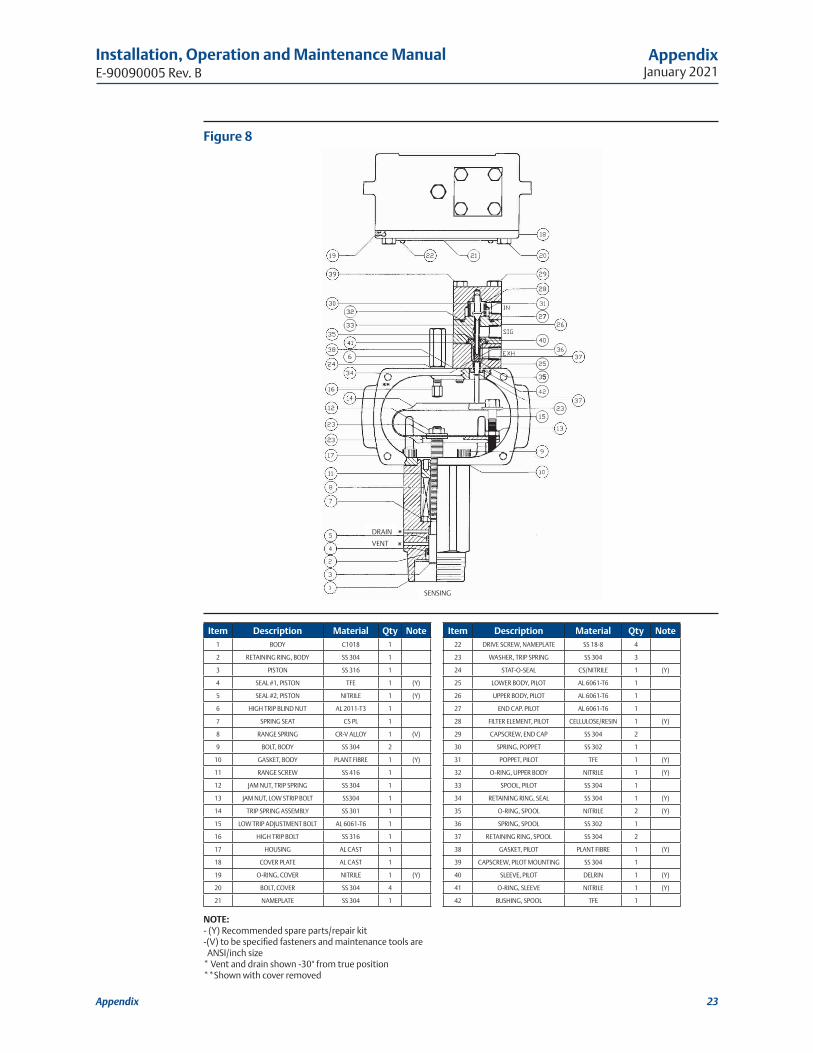
Figure 8
For complete list of sales and manufacturing sites, please visit www.emerson.com/actuationtechnologieslocations or contact us at [email protected]
World Area Configuration Centers (WACC) offer sales support, service, inventory and commissioning to our global customers. Choose the WACC or sales office nearest you:
NORTH & SOUTH AMERICA 19200 Northwest FreewayHouston TX 77065USAT +1 281 477 4100