27
BETTIS SERVICE INSTRUCTIONS FOR MODELS GTD SERIES ACTUATORS PART NUMBER: 133893 REVISION: “B” DATE: APRIL 2003
BETTIS
SERVICE INSTRUCTIONS
FOR MODELS
GTD SERIES
ACTUATORS
PART NUMBER: 133893
REVISION: “B”
DATE: APRIL 2003
Bettis P/N 133893Revision “B”Page 1 of 26
CONTENTS
SECTION 1.0 – INTRODUCTION PAGE
1.1 General Service Information ..................................................................... 21.2 Definitions .................................................................................................. 31.3 General Safety Information ....................................................................... 31.4 Bettis Reference Materials ........................................................................ 31.5 Service Support Items ............................................................................... 31.6 Lubrication Requirements ......................................................................... 31.7 Fluid Requirements ................................................................................... 31.8 General Tool Information .......................................................................... 4
SECTION 2.0 - ACTUATOR DISASSEMBLY
2.1 General Disassembly ................................................................................ 42.2 GTD Gas Cylinder Disassembly ............................................................... 42.3 GTO Oil Cylinder Disassembly ................................................................. 52.4 Drive Module Disassembly ....................................................................... 6
SECTION 3.0 – ACTUATOR REASSEMBLY
3.1 General Reassembly ................................................................................ 83.2 Drive Module Reassembly ........................................................................ 93.3 GTD Gas Cylinder Reassembly ............................................................... 113.4 GTO Oil Cylinder Reassembly ................................................................. 153.5 Actuator Testing ........................................................................................ 17
SECTION 4.0 – GTO MODULE REMOVAL AND INSTALLATION
4.1 GTO Oil Cylinder Removal ....................................................................... 174.2 GTO Oil Cylinder Installation .................................................................... 18
SECTION 5.0 – ACTUATOR SUPPORT INFORMATION
5.1 Weight Table ............................................................................................. 205.2 GTD01 Tool Table ..................................................................................... 215.3 GTD2 Tool Table ....................................................................................... 225.4 GTD3 Tool Table ....................................................................................... 235.5 GTD4 Tool Table ....................................................................................... 245.6 GTD5 Tool Table ....................................................................................... 255.7 GTD7 Tool Table ....................................................................................... 26
Bettis P/N 133893Revision “B”Page 2 of 26
SECTION 1 - INTRODUCTION
1.1 GENERAL SERVICE INFORMATION
1.1.1 This service procedure is offered as a guide to enable general maintenance to beperformed on Bettis GTD01X0X, GTD2X0X, GTD3X0X, GTD4X0X, GTD5X0X, andGTD7X0X Double Acting Series Actuators. These actuators will have one single GTD gascylinder (Gas) utilizing tie bar construction and one single GTO oil cylinder (Hydraulic)utilizing tie bar construction.
1.1.2 Normal recommended service interval for this actuator series is five years to maximum totallife cycle.
NOTE: Storage time is counted as part of the service interval.
1.1.3 This procedure is applicable with the understanding that all electrical power and gaspressure has been removed from the actuator.
1.1.4 Remove all piping and mounted accessories that will interfere with the actuatorassemblies(s) that are to be worked on.
1.1.5 This procedure should only be implemented by a technically competent technician whoshould take care to observe good workmanship practices.
1.1.6 Numbers in parentheses, ( ) indicate the bubble number (reference number) used on theBettis Assembly Drawing and Actuator Parts List.
1.1.7 This procedure is written using the stop screw plug side of the housing (1-10) as areference and this side will be considered the front side of the actuator. The housing cover(1-20) will be the top of the actuator.
1.1.8 Actuator Cylinder/Module weights are listed in Section 5 Table 5.1.
1.1.9 When removing seals from seal grooves, use a commercial seal removing tool or a smallscrewdriver with sharp corners rounded off.
1.1.10 Use a non-hardening thread sealant on all pipe threads.
CAUTION: Apply the thread sealant per the manufacture's instructions.
1.1.11 Bettis recommends that disassembly of the actuator should be done in a clean area on awork bench.
Bettis P/N 133893Revision “B”Page 3 of 26
1.2 DEFINITIONS
WARNING: If not observed, user incurs a high risk of severe damage to actuatorand/or fatal injury to personnel.
CAUTION: If not observed, user may incur damage to actuator and/or injury topersonnel.
NOTE: Advisory and information comments provided to assist maintenancepersonnel to carry out maintenance procedures.
1.3 GENERAL SAFETY INFORMATION Products supplied by Bettis, in its "as shipped" condition,are intrinsically safe if the instructions contained within this Service Instruction are strictly adhered toand executed by well trained, equipped, prepared and competent personnel.
WARNING: For the protection of personnel working on Bettis actuators, this procedureshould be reviewed and implemented for safe disassembly and reassembly.Close attention should be noted to the WARNINGS, CAUTIONS and NOTEScontained in this procedure.
WARNING: This procedure should not supersede or replace any customers plant safetyor work procedures. If a conflict arises between this procedure and thecustomers procedures the differences should be resolved in writing betweenan authorized customers representative and an authorized Bettisrepresentative.
1.4 BETTIS REFERENCE MATERIALS
1.4.1 Assembly Drawing for GTD01 through GTD7 Series Actuators use part number 133202.
1.5 SERVICE SUPPORT ITEMS
1.5.1 Bettis Service Kits.
1.5.2 Non-hardening thread sealant.
1.6 LUBRICATION REQUIREMENTS
1.6.1 Bettis ESL-4, 5 & 10 lubricant. This lubricant is to be used in the Drive Module and GTDGas Cylinder. NOTE: Bettis ESL-4, 5 & 10 lubricant tube(s) are contained in the BettisService Kits.
1.6.2 Lubricants, other than listed in step 1.6.1, should not be used without prior written approvalof Bettis Product Engineering.
1.7 FLUID REQUIREMENTS
1.7.1 For use in the GTO Oil Cylinder use Dexron Automatic Transmission Fluid, or as specified.
1.7.2 This fluid is the recommended fluid only and does not limit the use of other hydraulic fluidscompatible with supplied seals and coatings.

Bettis P/N 133893Revision “B”Page 4 of 26
1.8 GENERAL TOOL INFORMATION
1.8.1 Tools: All tools are American Standard inch. Large adjustable wrench, two (2) largescrewdrivers, Allen wrench set, set of open/box-end wrenches, rubber or leather mallet,torque wrench (up to 5,000 inch pounds), breaker bar, and a 1/2" drive socket set. Forrecommended tool and wrench sizes refer to Section 5 Tables 5.2 through 5.7
SECTION 2 - ACTUATOR DISASSEMBLY
2.1 GENERAL DISASSEMBLY
WARNING: It is very possible, that the actuator may contain a dangerous gas such as(Sour gas/H2S, Oxygen, Nitrogen, etc.) and/or liquids such as (Condense,Descalers, Petroleum bases, etc.). Ensure that all proper measures havebeen taken to prevent dangerous exposure or release of these types ofresidues before commencing any work.
2.1.1 Section 2 - Actuator Disassembly is written to either completely disassemble the entireactuator or can be used to disassemble individual actuator assemblies as needed (i.e.,GTD Gas Cylinder, Drive Module or GTO Oil Cylinder).
2.1.2 The GTD gas cylinder is to be disassembled while still attached to the Drive Module.
2.1.3 The GTO oil cylinder can be disassembled while still attached to the Drive Module or it canbe removed from the Drive Module and disassembled separate to the actuator (refer toSection 5 – Module, Cylinder Removal And Installation).
CAUTION: Using some means to contain hydraulic fluid as the tubing (piping) isdisconnect from the GTO outer end cap (7-80) and inner end cap (7-10).
2.1.4 Disconnect all hydraulic fluid lines to GTO oil cylinder outer end cap (7-80) and inner endcap (7-10). Drain as much of the hydraulic fluid as possible.
2.1.5 To ensure correct re-assembly; that is, with GTO oil cylinder or GTD gas cylinder on sameend of Drive Module as was, mark or tag right (or left) and mark mating surfaces.
2.2 GTD GAS CYLINDER DISASSEMBLY
NOTE: 1. Review Section 2 notes and steps 2.1.1 through 2.1.5 General Disassembly beforeproceeding with GTD gas cylinder disassembly.
WARNING: If not already removed disconnect all operating pressure from actuator GTDgas cylinder .

Bettis P/N 133893Revision “B”Page 5 of 26
2.2.1 Mark and record location of the ports on outer end cap (3-80) and inner end cap (3-10).
2.2.2 The setting of stop screw (3-180) should be checked and setting recorded before loosenedor removed. NOTE: The stop screw will be removed later in this procedure.
2.2.3 Remove the jam nut (3-190) and o-ring seal (4-100) from stop screw (3-180).
2.2.4 Remove hex nuts (3-90), with lockwashers (3-95), from tie bars (3-20).
2.2.5 Remove outer end cap (3-80) from cylinder (3-70). and tie bars (3-20).
2.2.6 Remove stop screw assembly (3-180) from the inboard side of outer end cap (3-80).
2.2.7 Unscrew and remove tie bars (3-20) from inner end cap (3-10).
2.2.8 Remove cylinder (3-70) from piston (3-30) and inner end cap (3-10).
2.2.9 Refer to assembly drawing page 2 of 2 Detail "C". Remove two split ring halves (3-50) andone retainer ring (3-60) from outboard end of piston rod assembly (3-40).
2.2.10 Remove the piston (3-30) from piston rod assembly (3-40).
2.2.11 On model GTD4008.0 remove the end cap/cylinder adapter (3-260) from inner end cap(3-10).
2.2.12 Remove o-ring seal (4-70) from piston rod assembly (3-40).
2.2.13 Remove the remaining two split ring halves (3-50) and one retainer ring (3-60) from pistonrod assembly (3-40).
2.2.14 Remove socket cap screws (3-115) with lockwashers (3-110) from inner end cap (3-10).
2.2.15 Refer to assembly drawing page 2 of 2 Detail "B". Remove hex nuts (3-105) from socketcap screws (3-100).
2.2.16 Remove socket cap screws (3-100) with lockwashers (3-110) from inner end cap (3-10).
2.2.17 Remove inner end cap (3-10) off of piston rod assembly (3-40).
2.2.18 Unscrew and remove piston rod assembly (3-40) from drive module.
2.2.19 It is not necessary to remove pipe plugs (3-210) from inner end cap (3-10) and outer endcap (3-80) for normal or routine actuator service.
2.3 GTO OIL CYLINDER DISASSEMBLY
NOTE: Review Section 2 notes and steps 2.1.1 through 2.1.4 General Disassembly beforeproceeding with GTO oil cylinder disassembly.
NOTE: The GTO oil cylinder can either be disassembled piece by piece or removed per Section4.1 and disassembled on a work bench per the following steps.

Bettis P/N 133893Revision “B”Page 6 of 26
2.3.1 Mark and record location of the ports on outer end cap (7-80)) and inner end cap (7-10).
2.3.2 The setting of stop screw (7-180) should be checked and setting recorded before loosenedor removed. NOTE: The stop screw will be removed later in this procedure.
2.3.3 Remove the jam nut (7-190) from stop screw (7-180).
2.3.4 Remove stop screw (7-180) from outer end cap (7-80).
2.3.5 Remove hex nuts (7-90), with lockwashers (7-95), from tie bars (7-20).
2.3.6 Remove outer end cap (7-80) from cylinder (7-70) and tie bars (7-20).
2.3.7 Unscrew and remove tie bars (7-20) from inner end cap (7-10).
2.3.8 Remove the cylinder (7-70) from piston (7-30) and inner end cap (7-10).
2.3.9 Refer to assembly drawing page 2 of 2 Detail "E". Remove two split ring halves (7-50) andone retainer ring (7-60) from outboard end of piston rod assembly (7-40).
2.3.10 Remove the piston (7-30) from piston rod assembly (7-40).
2.3.11 Remove the o-ring seal (8-70) from piston rod assembly (7-40).
2.3.12 Remove the remaining two split ring halves (7-50) and one retainer ring (7-60) from pistonrod assembly (7-40).
2.3.13 Remove socket cap screws (7-115) with lockwashers (7-110) from inner end cap (7-10).
2.3.14 Refer to assembly drawing page 2 of 2 Detail "D". Remove hex nuts (7-105) from socketcap screws (7-100).
2.3.15 Remove socket cap screws (7-100) with lockwashers (7-110) from inner end cap (7-10).
2.3.16 Remove inner end cap (7-10) off of piston rod assembly (7-40).
2.3.17 Unscrew and remove piston rod assembly (7-40) from drive module.
2.3.18 It is not necessary to remove pipe plugs (7-210) from inner end cap (7-10) and outer endcap (7-80) for normal or routine actuator service.
2.4 DRIVE MODULE DISASSEMBLY
NOTE: Review Section 2 notes and steps 2.1.1 through 2.1.5 General Disassembly beforeproceeding with Drive Module Disassembly.
2.4.1 If not already removed remove piston rod assemblies (3-40) and (7-40) from drive module(1-10).
NOTE: For steps 2.4.2 through 2.4.9 refer to assembly drawing page 2 of 2 Section A-A and Detail“A”.
Bettis P/N 133893Revision “B”Page 7 of 26
2.4.2 Before removing position indicator (1-220), record or mark it's position. Remove positionindicator (1-220).
NOTE: Step 2.4.3 is used only on GTD01, GTD2 and GTD3 Drive Modules. Drive Modules GTD4and GTD5 will skip steps 2.4.3 and continue with step 2.4.4.
2.4.3 Remove one vent check assembly (13) from top of housing cover (1-20).
2.4.4 Unscrew and remove hex cap screws (1-160) with lockwashers (1-170) from yoke cover(1-150).
2.4.5 Remove yoke cover (1-150) from housing cover (1-20).
2.4.6 Mark and record the orientation of the position indicator assembly (1-140) in relation to thetop of yoke (1-70).
2.4.7 Remove position indicator assembly (1-140) from top of yoke (1-70).
2.4.8 Remove spring pin (1-100) from top of yoke (1-70).
2.4.9 Remove hex cap screws (1-110), with lockwashers (1-115) or with lockwashers (1-170),from housing cover (1-20).
NOTE: Steps 2.4.10 and 2.4.11 are used only on GTD7 drive module (refer to assembly drawingnote number five). Drive modules GTD01, GTD2, GTD3, GTD4 and GTD5 will skip steps2.4.10 and 2.4.11 and continue with step 2.4.12.
2.4.10 Remove hex cap screws (1-120), with lockwashers (1-115), from housing cover (1-20).
2.4.11 Using hex cap screws (1-110), install into holes vacated by hex cap screws (1-120). Usethese hex cap screws to jack the housing cover up for removal. Alternately rotate the hexcap screw clockwise until housing cover (1-20) is clear of groove pins (1-130).
NOTE: GTD01, GTD2, GTD3 and GTD4 model housing cover (1-20) will have cast tabs for placingprying tools to aid in cover removal.
2.4.12 Remove housing cover (1-20) from housing (1-10).
NOTE: Groove pins (1-130) will remain in housing cover (1-20) when housing cover is removedfrom housing (1-10). Groove pins (1-130) should not be removed from housing cover(1-20) unless they are damaged and require new replacements.
2.4.13 Remove guide bar (1-90) from housing (1-10).
2.4.14 Rotate the arms of yoke (1-70) to the center position of housing (1-10).
2.4.15 Remove yoke (1-70) with yoke pin (1-80), guide block assembly (1-30) and two yoke/guideblock bushings (2-30) by lifting yoke up and out of the housing (1-10).
2.4.16 Remove yoke pin (1-80) by inserting 3/8"-16 UNC screw into top of the yoke pin and pullstraight up and out.
Bettis P/N 133893Revision “B”Page 8 of 26
2.4.17 Remove the guide block assembly (1-30) from between the arms of yoke (1-70).
2.4.18 Remove the yoke/guide block bushing (2-30) from top of guide block assembly (1-30).
2.4.19 Remove the yoke/guide block bushing (2-30) from the top of the lower yoke arm of yoke(1-70).
2.4.20 Unscrew and remove two stop screw plugs (1-180) from housing (1-10).
2.4.21 Housing (1-10) vent check assembly removal as follows:
2.4.21.1 GTD01, GTD2 and GTD3 housing (1-10) unscrew and remove one ventcheck assembly (13) from the front of housing (1-10).
2.4.21.2 GTD4 through GTD7 housing (1-10) unscrew and remove two vent checkassemblies (13) from the front of housing (1-10).
2.4.22 The following items do not need to be removed from their assembled locations unless beingreplaced by new items: Two yoke bearings (2-40), yoke pin bearing and yoke pin thrustbearing (2-10).
SECTION 3 - ACTUATOR REASSEMBLY
3.1 GENERAL REASSEMBLY
CAUTION: Only new seals, that are still within the seals expectant shelf life, should beinstalled into actuator being refurbished.
3.1.1 Remove and discard all old seals and gaskets.
3.1.2 All parts should be cleaned to remove all dirt and other foreign material prior to inspection.
3.1.3 All parts should be thoroughly inspected for excessive wear, stress cracking, galling andpitting. Attention should be directed to threads, sealing surfaces and areas that will besubjected to sliding or rotating motion. Sealing surfaces of the cylinder and piston rodassembly must be free of deep scratches, pitting, corrosion and blistering or flaking coating.
CAUTION: Actuator parts that reflect any of the above listed characteristics should bereplaced with new parts.
3.1.4 Before installation coat all moving parts with a complete film of lubricant. Coat all seals witha complete film of lubricant, before installing into seal grooves.
Bettis P/N 133893Revision “B”Page 9 of 26
NOTE: The parts and seals used in the actuator drive module and GTD gas cylinder will beassembled using lubricant as identified in Section 1 step 1.6.1. The parts and seals used inthe actuator GTO oil cylinder will be assembled using lubricant as identified in Section 1step 1.7.1.
3.2 DRIVE MODULE REASSEMBLY
NOTE: Review section 3.1 General Reassembly before proceeding with Drive ModuleReassembly.
3.2.1 If the guide bar bearings are being replaced install new bearings into guide block assembly(1-30).
NOTE: The guide bar bearing must be press fit into guide block guide bar bore with the seamlocated ±5° degrees of the top or bottom centerline as shown in section A-A.
3.2.2 If the two yoke bearings (2-40) are being replaced, install new bearing into housing cover(1-20) and housing (1-10).
NOTE: The yoke bearing (2-40) must be press fit into housing (1-10) and housing cover (1-20).Install the yoke bearings with the bearing seam located 45° ±5° degrees from the yoke armslot when yoke (1-70) is rotated to its full clockwise position.
3.2.3 If the two yoke pin thrust bearings (2-10) are being replaced install new bearing intohousing cover (1-20) and housing (1-10).
3.2.4 Lubricate two yoke/guide block bushings (2-30) and install onto top and bottom sides ofguide block assembly (1-30).
3.2.5 Install guide block assembly (1-30), with yoke/guide block bushings (2-30), between armsof yoke (1-70).
3.2.6 Install o-ring seal (2-50) into inner diameter o-ring groove in the bottom of housing (1-10).
3.2.7 Coat the bearing surfaces of the yoke (1-70) with lubricant and install into housing (1-10).
3.2.8 Align hole in guide block assembly (1-30) with the matching holes in the two yoke/guideblock bushings (2-30) and the slots in the arms of yoke (1-70).
NOTE: The yoke pin can be held in place by installing a screw into the .375-16UNC tapped hole inthe upper end of yoke pin (1-80).
3.2.9 Install yoke pin (1-80) by inserting into the upper yoke arm, upper yoke/guide block bushing,guide block assembly, lower yoke/guide block bushing, lower yoke arm and resting onlower yoke pin thrust bearing (2-10).
3.2.10 Install guide bar (1-90) into either side of housing (1-10) by inserting through the housing,through guide block assembly and then insert the guide bar into the other side of housing(1-10).
Bettis P/N 133893Revision “B”
Page 10 of 26
3.2.11 Refer to assembly drawing page 2 of 2 Section A-A. Install spring pin (1-100) into the top ofyoke (1-70).
3.2.12 Install position indicator assembly (1-140) onto the top of yoke (1-70) and over spring pin(1-100). NOTE: Refer to Section 2 step 2.4.6 for correct installation position.
3.2.13 Install o-ring (2-50) into housing cover (1-20).
3.2.14 Install housing cover o-ring (2-60) into housing cover (1-20).
3.2.15 Install the housing cover (1-20), being careful not to damage o-ring seals (2-50) and (2-60).
3.2.16 Place lockwashers (1-115) onto hex cap screws (1-110).
NOTE: On GTD7 model actuators apply thread adhesive, Locktite 242, to threads of hex capscrews (1-110). Reference assembly drawing note number seven.
3.2.17 Install hex cap screws (1-110) with lockwashers (1-115) through housing cover (1-20) andinto housing (1-10). NOTE: Leave hex cap screws (1-110) finger tight - do not tighten.
3.2.18 NOTE: Do this step only if groove pins (1-130) have been pulled or if the pins are beingreplaced. Drive groove pins (1-130) through housing cover (1-20) and into housing (1-10).The groove pins should be flush with the cover.
3.2.19 Torque tighten hex cap screws (1-110) until a final lubricated torque, as listed in thefollowing table, has been achieved.
HOUSING COVER SCREW QUANTITY AND TORQUE TABLETORQUE
(±5 % Percent)TORQUE
(±5 % Percent)MODE QTY
FT-lb N-m
MODEL QTY
FT-lb N-mGTD01 4 40 54 GTD7 8 100 136GTD2 6 40 54 GTD8 12 100 136GTD3 8 40 54 GTD10 16 100 136GTD4 8 40 54 GTD13 20 340 461GTD5 8 100 136
NOTE: Complete step 3.2.20 on GTD5, through GTD7 model actuators. For GTD01 throughGTD4 model actuators skip step 3.2.20 and proceed to step 3.2.21.
3.2.20 On GTD5 through GTD7 models (refer to assembly drawing note number five).
3.2.20.1 Place lockwashers (1-115) onto hex cap screws (1-120).
NOTE: Hex cap screw (1-120) are only used as hole fillers and to protect threadsfrom environment.
3.2.20.2 Install and tighten hex cap screws (1-120) with lockwashers (1-115).
Bettis P/N 133893Revision “B”
Page 11 of 26
NOTE: For steps 3.2.21 through 3.2.25 refer to assembly drawing page 2 of 2 Section A-A andDetail “A”.
3.2.21 Install thrust bearing (2-110) onto position indicator (1-140).
3.2.22 Install o-ring seal (2-100) onto position indicator (1-140).
3.2.23 Install upper bearing (2-120) into yoke cover (1-150).
3.2.24 Install rod wiper (2-80) into yoke cover (1-150).
3.2.25 Install o-ring seal (2-70) into yoke cover (1-150).
3.2.26 Install yoke cover (1-150) onto housing cover (1-20) and over position indicator assembly(1-140). NOTE: During yoke cover installation be careful not to damage o-ring seal (2-70)and rod wiper (2-80).
3.2.27 Place lockwashers (1-170) onto hex cap screws (1-160).
3.2.28 Install and tighten hex cap screws (1-160) with lockwashers through yoke cover (1-150)and into housing cover (1-20).
3.2.29 Vent check assembly installation as follows:
3.2.29.1 GTD01, GTD2 and GTD3 housing (1-10) using pipe sealant install onevent check assembly (13) into the front of housing (1-10).
3.2.29.2 GTD01, GTD2 and GTD3 housing (1-10) using pipe sealant install onevent check assembly (13) into the top area of housing cover (1-20).
3.2.29.3 GTD4 through GTD7 housing (1-10) using pipe sealant install two ventcheck assemblies (13) into the front of housing (1-10).
3.2.30 NOTE: Refer to Section 2 step 2.4.2 for correct position indicator placement. Install positionindicator (1-220) over the exposed shaft of position indicator assembly (1-140).
3.2.31 Install o-ring seals (2-90) onto stop screw plugs (1-180).
3.2.32 Install and tighten two stop screw plugs (1-180) into two stop screw plug holes on the frontof housing (1-10).
3.3 GTD GAS CYLINDER REASSEMBLY
NOTE: Review Section 3.1 General Reassembly before proceeding with GTD gas cylinderreassembly.
NOTE: Reassemble the GTD gas cylinder on a work bench per the following steps and then installon the Drive Module per this section.
NOTE: In Section 3.3 where the step indicates to "lubricate or coat with lubricant", use lubricant aslisted in Section 1.6 for lubricating of the part being installed.

Bettis P/N 133893Revision “B”
Page 12 of 26
NOTE: For steps 3.3.2 through 3.3.5 refer to assembly drawing page 2 of 2 Detail “C”.
3.3.1 Lubricate piston rod assembly (3-40) with lubricant.
3.3.2 Install o-ring seal (4-70) into the seal groove in piston rod assembly (3-40).
3.3.3 Install two split ring halves (3-50) into the inner most groove in piston rod assembly (3-40)and retain with one retainer ring (3-60).
3.3.4 Install piston (3-30) onto piston rod assembly (3-40) and up against split rings installed instep 3.3.3.
3.3.5 Install two split ring halves (3-50) into the outer most groove in piston rod assembly (3-40)and retain with one retainer ring (3-60).
3.3.6 Apply lubricant to the bore of cylinder (3-70).
3.3.7 Coat one piston bearing (4-45) with lubricant and install into the piston external bearinggroove.
3.3.8 Install piston (3-30), with piston rod assembly (3-40), into cylinder (3-70) leave the innermost piston seal groove exposed outside of the cylinder.
3.3.9 Coat one piston seal (4-60) with lubricant and install into the exposed piston external sealgroove.
CAUTION: Install the piston seal with energizer ring facing outside edge of piston (3-30).
3.3.10 Push the piston through the cylinder (3-70) until the outboard piston seal groove is exposed.
NOTE: To move the piston (3-30) through the bore of cylinder (3-70) may require mechanicalassistance.
3.3.11 Coat one piston seal (4-60) with lubricant and install into the piston external seal groove.
CAUTION: Install the piston seal with energizer ring facing outside edge of piston (3-30).
NOTE: Step 3.3.12 is used only on GTD4008.0 actuator Models. All other actuator models will skipsteps 3.3.12 and continue with step 3.3.13.
3.3.12 GTD4008.0 actuator Models.
3.3.12.1 Install o-ring seal (4-40) onto outboard side of end cap/cylinder adapter(3-260).
3.3.12.2 Refer to assembly drawing page 1 of 2 Detail "F". Install o-ring seal (4-35) ontoinboard face of end cap/cylinder adapter (3-260).
3.3.12.3 Install end cap/cylinder adapter (3-260) over piston rod assembly (3-40) andinto inboard end of cylinder (3-70).
Bettis P/N 133893Revision “B”
Page 13 of 26
3.3.13 Refer to assembly drawing page 2 of 2 Detail "B". Coat Polypak seal (4-30) with lubricantand install, lip first, into inner end cap (3-10).
CAUTION: Install Polypak seal with energizer ring facing piston side of inner end cap.
3.3.14 Install rod bushing (4-20) into inner end cap (3-10).
3.3.15 Install rod wiper (4-10) into inner end cap (3-10).
3.3.16 Install one o-ring seal (4-90) into inboard face of inner end cap (3-10).
3.3.17 Install one o-ring seal (4-40) into outboard face of inner end cap (3-10).
3.3.18 Install inner end cap (3-10) onto piston rod assembly (3-40) and into inboard end of cylinder(3-70).
3.3.19 Install tie bars (3-20) through outer end cap (3-80) and into inner end cap (3-10). Screw alltie bars (3-20) into inner end cap (3-10) per instructions given in note number eight locatedon the assembly drawing page 1 0f 2.
3.3.20 Temporarily install outer end cap (3-80) into open end of cylinder (3-70).
3.3.21 Install the hex nuts (3-90) onto tie bars (3-20) and temporarily tighten against outer end cap(3-80).
3.3.22 Check to verify that o-ring seal (4-90) is properly seated in its seal groove located on thehousing side of inner end cap (3-10).
3.3.23 Using lifting equipment move the power module up to housing (1-10) and align piston rodassembly (3-40) with guide block assembly (1-30).
3.3.24 Using a male square drive extension, go through outer end cap (3-80) and screw piston rodassembly (3-40) into guide block assembly (1-30).
WARNING: When screwing piston rod assembly into guide block assembly (1-30) makecertain that the piston rod assembly threads do not cross-thread.
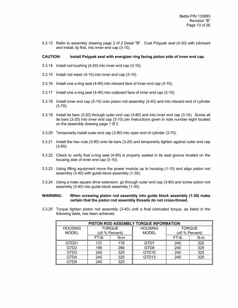
3.3.25 Torque tighten piston rod assembly (3-40) until a final lubricated torque, as listed in thefollowing table, has been achieved.
PISTON ROD ASSEMBLY TORQUE INFORMATIONTORQUE
(±5 % Percent)TORQUE
(±5 % Percent)HOUSINGMODEL
FT-lb N-m
HOUSINGMODEL
FT-lb N-mGTD01 131 178 GTD7 240 325GTD2 196 266 GTD8 240 325GTD3 240 325 GTD10 240 325GTD4 240 325 GTD13 240 325GTD5 240 325
Bettis P/N 133893Revision “B”
Page 14 of 26
3.3.26 Install lock washers (3-110) onto socket cap screws (3-115).
3.3.27 Install socket cap screws (3-115), with lockwashers (3-110), through inner end cap (3-10)and screw into housing (1-10).
3.3.28 Refer to assembly drawing page 2 of 2 Detail "B". Install lock washers (3-110) onto socketcap screws (3-100).
3.3.29 Install socket cap screws (3-100), with lockwashers (3-110), through inner end cap (3-10)and housing (1-10).
3.3.30 Install hex nuts (3-105) onto socket cap screws (3-100).
3.3.31 Remove hex nuts (3-90) from tie bars (3-20).
3.3.32 Remove outer end cap (3-80) from cylinder (3-70). and tie bars (3-20).
3.3.33 Lubricate stop screw (3-180) and install into the outer end cap (3-80). NOTE: The stopscrew is installed from the inboard side or cylinder side of the outer end cap (3-80).
3.3.34 Install o-ring seal (4-100) onto the out board side of the stop screw (3-180).
3.3.35 Install jam nut (3-190) onto the out board side of the stop screw (3-180).
NOTE: The pressure inlet ports of the inner and outer end caps should be positioned in the sameposition as recorded in Section 2 step 2.2.1.
3.3.36 Install outer end cap (3-80) over tie bars (3-20) and into open end of cylinder (3-70).
3.3.37 Install lockwashers (3-95) onto tie bars (3-20) and up against outer end cap (3-80).
3.3.38 Install hex nuts (3-90) onto tie bars (3-20) and up against lockwashers (3-95).
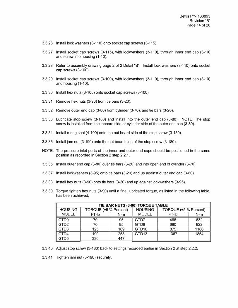
3.3.39 Torque tighten hex nuts (3-90) until a final lubricated torque, as listed in the following table,has been achieved.
TIE BAR NUTS (3-90) TORQUE TABLETORQUE (±5 % Percent) TORQUE (±5 % Percent)HOUSING
MODEL FT-lb N-mHOUSINGMODEL FT-lb N-m
GTD01 70 95 GTD7 466 632GTD2 70 95 GTD8 680 922GTD3 125 169 GTD10 875 1186GTD4 190 258 GTD13 1367 1854GTD5 330 447
3.3.40 Adjust stop screw (3-180) back to settings recorded earlier in Section 2 at step 2.2.2.
3.3.41 Tighten jam nut (3-190) securely.
Bettis P/N 133893Revision “B”
Page 15 of 26
3.3.42 If removed apply thread sealant to two pipe plugs (3-210) and install into the ports of outerend cap (3-10) and inner end cap (3-80).
3.4 GTO OIL CYLINDER REASSEMBLY
NOTE: Review section 3.1 General Reassembly before proceeding with GTO oil cylinderreassembly.
NOTE: Reassemble the GTO oil cylinder on a work bench per the following steps and then installon the Drive Module per Section 4.
NOTE: In section 3.4 where the step indicates to "lubricate, coat or apply fluid", use hydraulic fluidfor lubricating the part being installed.
3.4.1 Lubricate piston rod assembly (7-40) with fluid.
NOTE: For steps 3.4.2 through 3.4.7 refer to assembly drawing page 2 of 2 Detail “E”.
3.4.2 Install o-ring seal (8-70) into the seal groove in piston rod assembly (7-40).
3.4.3 Install two split ring halves (7-50) into the inner most groove in piston rod assembly (7-40)and retain with one retainer ring (7-60).
3.4.4 Install piston (7-30) onto piston rod assembly (7-40) and up against split rings installed instep 3.4.3.
3.4.5 Install two split ring halves (7-50) into the outer most groove in piston rod assembly (7-40)and retain with one retainer ring (7-60).
3.4.6 Apply fluid to the bore of cylinder (7-70).
3.4.7 Coat one piston bearing (8-45) with fluid and install into the piston external seal groove.
3.4.8 Install piston (7-30), with piston rod assembly (7-40), into cylinder (7-70) leave the innermost piston seal groove exposed out side of the cylinder.
3.4.9 Coat one piston seal (8-60) with fluid and install into the exposed piston external sealgroove.
CAUTION: Install the piston seal with energizer ring facing outside edge of piston (7-30).
3.4.10 Push the piston through the cylinder (7-70) until the outboard piston seal groove is exposed.
NOTE: To move the piston (7-30) through the bore of cylinder (7-70) may require mechanicalassistance.
3.4.11 Coat one piston seal (8-60) with fluid and install into the exposed piston external sealgroove.
CAUTION: Install the piston seal with energizer ring facing outside edge of piston (7-30).
Bettis P/N 133893Revision “B”
Page 16 of 26
3.4.12 Refer to assembly drawing page 2 of 2 Detail "D". Coat Polypak seal (8-30) with hydraulicfluid and install, lip first, into inner end cap (7-10).
CAUTION: Install the Polypak seal with energizer ring facing piston side of inner endcap (7-10).
3.4.13 Install rod bushing (8-20) into inner end cap (7-10).
3.4.14 Install rod wiper (8-10) into inner end cap (7-10).
3.4.15 Install one o-ring seal (8-90) into inboard face of inner end cap (7-10).
3.4.16 Install one o-ring seal (8-40) into outboard face of inner end cap (3-10).
3.4.17 Install inner end cap (7-10) onto piston rod assembly (7-40) and into inboard end of cylinder(7-70).
3.4.18 Install two tie bars (7-20) into inner end cap (7-10). NOTE: the tie bars should be installedacross from each other.
3.4.19 Install one o-ring seal (8-40) into inboard face of outer end cap (7-80).
3.4.20 Install outer end cap (7-80) into open end of cylinder (7-70).
NOTE: The pressure inlet ports of the inner and outer end caps should be positioned in the sameposition as recorded in Section 2 step 2.2.3.
3.4.21 Install the remaining tie bars (7-20) through outer end cap (7-80) and into inner end cap(7-10). Screw all tie bars (7-20) into inner end cap (7-10) per instructions given in notenumber eight located on the assembly drawing page 1 of 2.
3.4.22 Install lockwashers (7-95) onto tie bars (7-20) and up against outer end cap (7-80).
3.4.23 Install hex nuts (7-90) onto tie bars (7-20) and up against lockwashers (7-95).
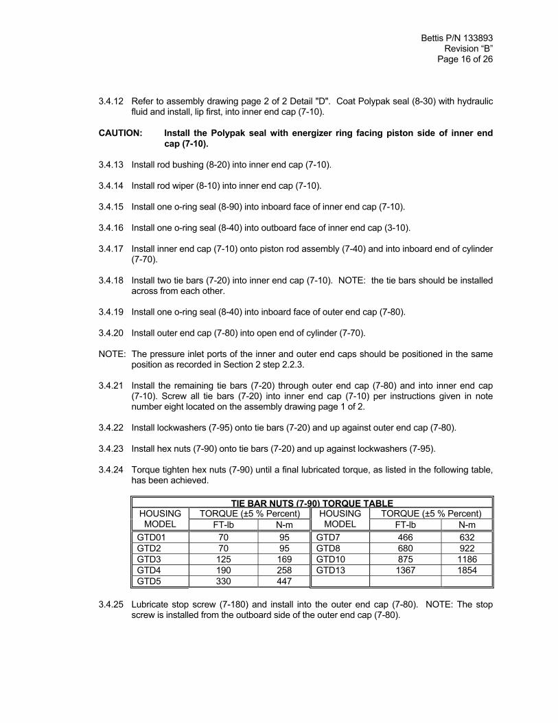
3.4.24 Torque tighten hex nuts (7-90) until a final lubricated torque, as listed in the following table,has been achieved.
TIE BAR NUTS (7-90) TORQUE TABLETORQUE (±5 % Percent) TORQUE (±5 % Percent)HOUSING
MODEL FT-lb N-mHOUSINGMODEL FT-lb N-m
GTD01 70 95 GTD7 466 632GTD2 70 95 GTD8 680 922GTD3 125 169 GTD10 875 1186GTD4 190 258 GTD13 1367 1854GTD5 330 447
3.4.25 Lubricate stop screw (7-180) and install into the outer end cap (7-80). NOTE: The stopscrew is installed from the outboard side of the outer end cap (7-80).
Bettis P/N 133893Revision “B”
Page 17 of 26
3.4.26 Install o-ring seal (8-100) onto the out board side of the stop screw (7-180).
3.4.27 Install jam nut (7-190) onto the out board side of the stop screw (7-180).
3.4.28 Adjust stop screw (7-180) back to settings recorded earlier in Section 2 at step 2.3.2.
3.4.29 Tighten jam nut (7-190) securely.
3.4.30 If removed apply thread sealant to two pipe plugs (7-210) and install into the ports of outerend cap (7-10) and inner end cap (7-80).
3.4.31 For installation of the GTO oil cylinder onto Drive Module (housing) refer to Section 4 step4.2 for GTO oil cylinder installation instructions.
3.5 ACTUATOR TESTING
3.5.1 Leakage Test - All sources of leakage to atmosphere and across pistons are to be checked,using pneumatic pressure.
3.5.2 Cycle the actuator five time at 10 % percent of the operating pressure, as listed on theactuator name tag under max. pressure or use a minimum 80 to 100 psig pressure.
NOTE: If excessive leakage across the piston remains, the actuator must be disassembled and thecause of leakage must be determined and corrected.
3.5.3 Apply operating pressure as listed in step 3.5.2 to one side of the piston and allow theactuator to stabilize.
3.5.4 Repeat the above procedure for the opposite side of the piston.
3.5.5 If an actuator was disassembled and repaired, the above leakage test must be performedagain.
SECTION 4 - MODULE, CYLINDER REMOVAL AND INSTALLATION
NOTE: The GTO oil cylinder is the only GTD actuator component that can be remove as a module.
4.1 GTO OIL CYLINDER REMOVAL
CAUTION: Using some means to contain hydraulic fluid as the tubing (piping) isdisconnect from the GTO outer end cap (7-80) and inner end cap (7-10).
4.1.1 Disconnect all hydraulic fluid lines to GTO oil cylinder outer end cap (7-80) and inner endcap (7-10). Drain as much of the hydraulic fluid as possible.
Bettis P/N 133893Revision “B”
Page 18 of 26
4.1.2 The setting of stop screw (7-180) should be checked and setting recorded before stopscrews are loosened or removed. NOTE: Stop screws will be removed later in thisprocedure.
4.1.3 Loosen and back off jam nut (7-190) at least two rotations.
4.1.4 Remove stop screw (7-180) from outer end cap (7-80).
4.1.5 Using a male square drive extension, go through outer end cap (7-80), unscrew piston rodassembly (7-40) from guide block assembly (1-30).
WARNING: Use suitable lifting equipment to support the cylinder assembly.
4.1.6 Remove socket cap screws (7-115), with lockwashers (7-110), from inner end cap (7-10).
4.1.7 Remove hex nuts (7-105) from socket cap screws (7-100).
4.1.8 Remove GTO oil cylinder from actuator housing (1-10).
4.2 GTO OIL CYLINDER INSTALLATION
NOTE: Review section 3.1 General Reassembly before proceeding with GTO Hydraulic PowerModule Installation.
4.2.1 The setting of stop screw (7-180) should be checked and setting recorded before stopscrews are loosened or removed. NOTE: Stop screw (7–180) will be removed later in thisprocedure.
4.2.2 Loosen or remove the jam nut (7-190) from stop screw (7-180).
4.2.3 Remove stop screw (7-180) from outer end cap (7-80).
4.2.4 Check to verify that o-ring seal (8-90) is properly seated in its seal groove located on thehousing side of inner end cap (7-10).
4.2.5 Using lifting equipment move the oil cylinder up to housing (1-10) and align piston rodassembly (7-40) with guide block assembly (1-30).
4.2.6 Using a male square drive extension, go through the vacant stop screw hole located inouter end cap (7-80) and screw piston rod assembly (7-40) into guide block assembly(1-30).
WARNING: When connecting (screwing) piston rod assembly into guide block assembly(1-30) make certain that the piston rod assembly and guide block assemblythreads do not cross-thread.
4.2.7 Torque tighten piston rod assembly (7-40) until a final lubricated torque, as listed in thefollowing table, has been achieved.

Bettis P/N 133893Revision “B”
Page 19 of 26
PISTON ROD ASSEMBLY TORQUE INFORMATIONTORQUE
(±5 % Percent)TORQUE
(±5 % Percent)HOUSINGMODEL
FT-lb N-m
HOUSINGMODEL
FT-lb N-mGTD01 131 178 GTD7 240 325GTD2 196 266 GTD8 240 325GTD3 240 325 GTD10 240 325GTD4 240 325 GTD13 240 325GTD5 240 325
4.2.8 Install lock washers (7-110) onto socket cap screws (7-115).
4.2.9 Install socket cap screws (7-115), with lockwashers (7-110), through inner end cap (7-10)and screw into housing (1-10).
4.2.10 Install lock washers (7-110) onto socket cap screws (7-100).
4.2.11 Install socket cap screws (7-100), with lockwashers (7-110), through inner end cap (7-10)and housing (1-10).
4.2.12 Install and tighten hex nuts (7-105) onto socket cap screws (7-100).
4.2.13 Lubricate stop screw (7-180) and install into the outer end cap (7-80). NOTE: The stopscrew is installed from the outboard side of the outer end cap (7-80).
4.2.14 Verify that o-ring seal (8-100) is installed on the stop screw (7-180).
4.2.15 Install jam nut (7-190) onto the out board side of the stop screw (7-180).
4.2.16 Adjust stop screw (7-180) per step 4.2.16.1 or 4.2.16.2.
4.2.16.1 Adjust stop screw (7-180) back to settings recorded earlier in either step2.3.2 or 4.2.1.
4.2.16.2 Adjust stop screw (7-180) to setting as instructed by the valvemanufactures procedures for actuator stop requirements.
4.2.17 Tighten jam nut (7-190) securely.
Bettis P/N 133893Revision “B”
Page 20 of 26
SECTION 5 - ACTUATOR SUPPORT INFORMATION
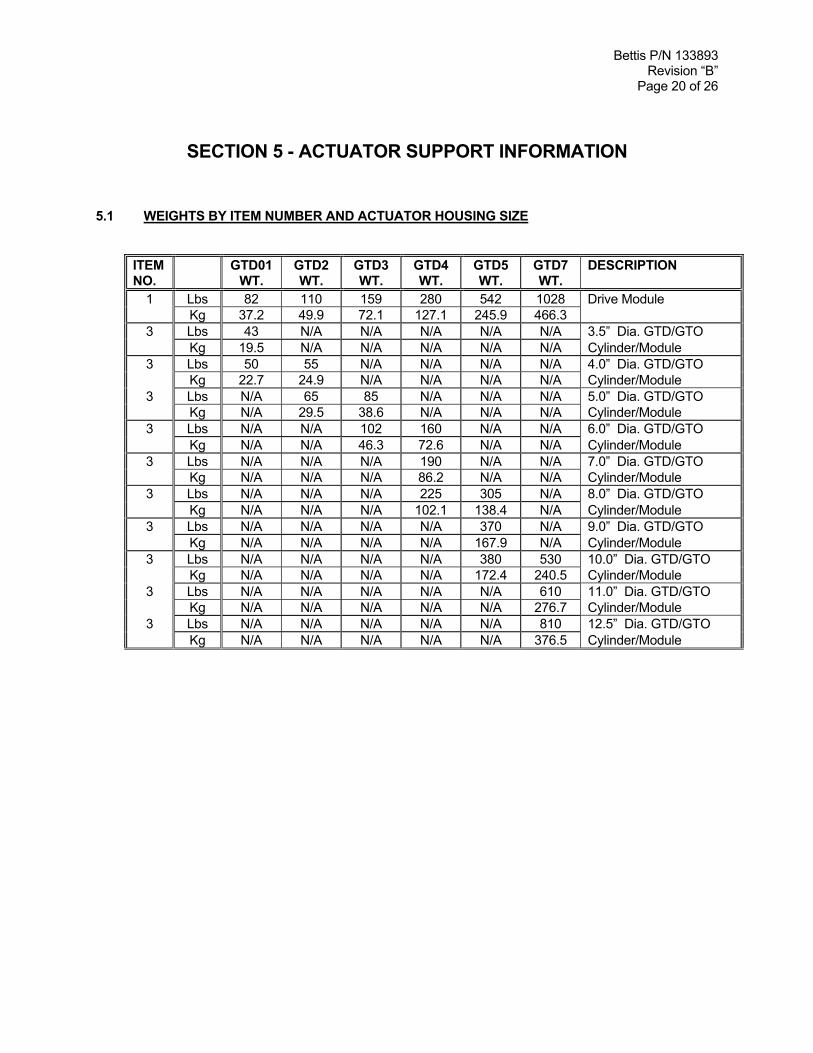
5.1 WEIGHTS BY ITEM NUMBER AND ACTUATOR HOUSING SIZE
ITEMNO.
GTD01WT.
GTD2WT.
GTD3WT.
GTD4WT.
GTD5WT.
GTD7WT.
DESCRIPTION
1 Lbs 82 110 159 280 542 1028 Drive ModuleKg 37.2 49.9 72.1 127.1 245.9 466.3
3 Lbs 43 N/A N/A N/A N/A N/A 3.5” Dia. GTD/GTOKg 19.5 N/A N/A N/A N/A N/A Cylinder/Module
3 Lbs 50 55 N/A N/A N/A N/A 4.0” Dia. GTD/GTOKg 22.7 24.9 N/A N/A N/A N/A Cylinder/Module
3 Lbs N/A 65 85 N/A N/A N/A 5.0” Dia. GTD/GTOKg N/A 29.5 38.6 N/A N/A N/A Cylinder/Module
3 Lbs N/A N/A 102 160 N/A N/A 6.0” Dia. GTD/GTOKg N/A N/A 46.3 72.6 N/A N/A Cylinder/Module
3 Lbs N/A N/A N/A 190 N/A N/A 7.0” Dia. GTD/GTOKg N/A N/A N/A 86.2 N/A N/A Cylinder/Module
3 Lbs N/A N/A N/A 225 305 N/A 8.0” Dia. GTD/GTOKg N/A N/A N/A 102.1 138.4 N/A Cylinder/Module
3 Lbs N/A N/A N/A N/A 370 N/A 9.0” Dia. GTD/GTOKg N/A N/A N/A N/A 167.9 N/A Cylinder/Module
3 Lbs N/A N/A N/A N/A 380 530 10.0” Dia. GTD/GTOKg N/A N/A N/A N/A 172.4 240.5 Cylinder/Module
3 Lbs N/A N/A N/A N/A N/A 610 11.0” Dia. GTD/GTOKg N/A N/A N/A N/A N/A 276.7 Cylinder/Module
3 Lbs N/A N/A N/A N/A N/A 810 12.5” Dia. GTD/GTOKg N/A N/A N/A N/A N/A 376.5 Cylinder/Module

Bettis P/N 133893Revision “B”
Page 21 of 26
5.2 GTD01 TOOL STYLE AND WRENCH SIZE
ITEMNO.
WRENCHSIZE
ITEMQTY
LOCATION ORDESCRIPTION
RECOMMENDEDTOOL STYLE
1-110 9/16” 4 Hex Cap Screws Socket1-160 ½” 4 Hex Cap Screws Socket1-180 1-1/16” 2 Hex Cap Screws Open End or Adjustable3-40 3/8” Sq. 1 Piston Rod Assembly Male Drive3-90 15/16” 4 Standard Hex Nuts Socket3-100 5/16” 4 Socket Cap Screws Allen3-105 9/16” 4 Standard Hex Nuts Open End Or Box end3-115 5/16” 4 Socket Cap Screws Allen3-180 3/4”Sq. 1 Stop Screw Assembly Open End or Adjustable3-190 1-13/16” 1 Heavy Hex Jam Nut Open End or Adjustable3-210 7/16” Sq. 2 Pipe Plug Open End or Adjustable7-40 3/8” Sq. 1 Piston Rod Assembly Male Drive7-90 15/16” 4 Standard Hex Nuts Socket7-100 5/16” 4 Socket Cap Screws Allen7-105 9/16” 4 Standard Hex Nuts Socket7-115 9/16” 4 Socket Cap Screws Allen7-180 3/4” 1 Stop Screw Assembly Open End or Adjustable7-190 1-13/16” 1 Heavy Hex Jam Nut Open End or Adjustable7-210 7/16” Sq. 2 Pipe Plug Open End or Adjustable
13 3/4” 2 Vent Check Assembly Open End
Bettis P/N 133893Revision “B”
Page 22 of 26
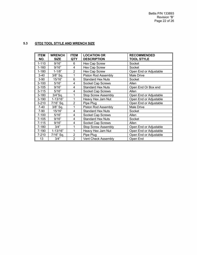
5.3 GTD2 TOOL STYLE AND WRENCH SIZE
ITEMNO.
WRENCHSIZE
ITEMQTY
LOCATION ORDESCRIPTION
RECOMMENDEDTOOL STYLE
1-110 9/16” 6 Hex Cap Screw Socket1-160 9/16” 4 Hex Cap Screw Socket1-180 1-1/8” 2 Hex Cap Screw Open End or Adjustable3-40 3/8” Sq. 1 Piston Rod Assembly Male Drive3-90 15/16” 6 Standard Hex Nuts Socket3-100 5/16” 4 Socket Cap Screws Allen3-105 9/16” 4 Standard Hex Nuts Open End Or Box end3-115 5/16” 4 Socket Cap Screws Allen3-180 3/4”Sq. 1 Stop Screw Assembly Open End or Adjustable3-190 1-13/16” 1 Heavy Hex Jam Nut Open End or Adjustable3-210 7/16” Sq. 2 Pipe Plug Open End or Adjustable7-40 3/8” Sq. 1 Piston Rod Assembly Male Drive7-90 15/16” 4 Standard Hex Nuts Socket7-100 5/16” 4 Socket Cap Screws Allen7-105 9/16” 4 Standard Hex Nuts Socket7-115 9/16” 4 Socket Cap Screws Allen7-180 3/4” 1 Stop Screw Assembly Open End or Adjustable7-190 1-13/16” 1 Heavy Hex Jam Nut Open End or Adjustable7-210 7/16” Sq. 2 Pipe Plug Open End or Adjustable
13 3/4” 2 Vent Check Assembly Open End

Bettis P/N 133893Revision “B”
Page 23 of 26
5.4 GTD3 TOOL STYLE AND WRENCH SIZE
ITEMNO.
WRENCHSIZE
ITEMQTY
LOCATION ORDESCRIPTION
RECOMMENDEDTOOL STYLE
1-110 9/16” 8 Hex Cap Screw Socket1-160 9/16” 4 Hex Cap Screw Socket1-180 1-5/16” 2 Hex Cap Screw Open End or Adjustable3-40 3/8” Sq. 1 Piston Rod Assembly Male Drive3-90 1-1/8” 6 Standard Hex Nuts Socket3-100 5/16” 4 Socket Cap Screws Allen3-105 9/16” 4 Standard Hex Nuts Open End Or Box end3-115 5/16” 4 Socket Cap Screws Allen3-180 3/4” 1 Stop Screw Assembly Open End or Adjustable3-190 1-13/16” 1 Heavy Hex Jam Nut Open End or Adjustable3-210 7/16” Sq. 2 Pipe Plug Open End or Adjustable7-40 3/8” Sq. 1 Piston Rod Assembly Male Drive7-90 1-1/8” 6 Standard Hex Nuts Socket7-100 5/16” 4 Socket Cap Screws Allen7-105 9/16” 4 Standard Hex Nuts Socket7-115 5/16” 4 Socket Cap Screws Allen7-180 3/4” 1 Stop Screw Assembly Open End or Adjustable7-190 1-13/16” 1 Heavy Hex Jam Nut Open End or Adjustable7-210 7/16” Sq. 2 Pipe Plug Open End or Adjustable
13 3/4” 2 Vent Check Assembly Open End
Bettis P/N 133893Revision “B”
Page 24 of 26
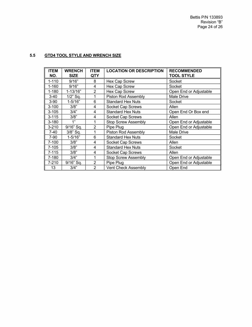
5.5 GTD4 TOOL STYLE AND WRENCH SIZE
ITEMNO.
WRENCHSIZE
ITEMQTY
LOCATION OR DESCRIPTION RECOMMENDEDTOOL STYLE
1-110 9/16” 8 Hex Cap Screw Socket1-160 9/16” 4 Hex Cap Screw Socket1-180 1-13/16” 2 Hex Cap Screw Open End or Adjustable3-40 1/2” Sq. 1 Piston Rod Assembly Male Drive3-90 1-5/16” 6 Standard Hex Nuts Socket3-100 3/8” 4 Socket Cap Screws Allen3-105 3/4” 4 Standard Hex Nuts Open End Or Box end3-115 3/8” 4 Socket Cap Screws Allen3-180 1” 1 Stop Screw Assembly Open End or Adjustable3-210 9/16” Sq. 2 Pipe Plug Open End or Adjustable7-40 3/8” Sq. 1 Piston Rod Assembly Male Drive7-90 1-5/16” 6 Standard Hex Nuts Socket7-100 3/8” 4 Socket Cap Screws Allen7-105 3/8” 4 Standard Hex Nuts Socket7-115 3/8” 4 Socket Cap Screws Allen7-180 3/4” 1 Stop Screw Assembly Open End or Adjustable7-210 9/16” Sq. 2 Pipe Plug Open End or Adjustable
13 3/4” 2 Vent Check Assembly Open End
Bettis P/N 133893Revision “B”
Page 25 of 26
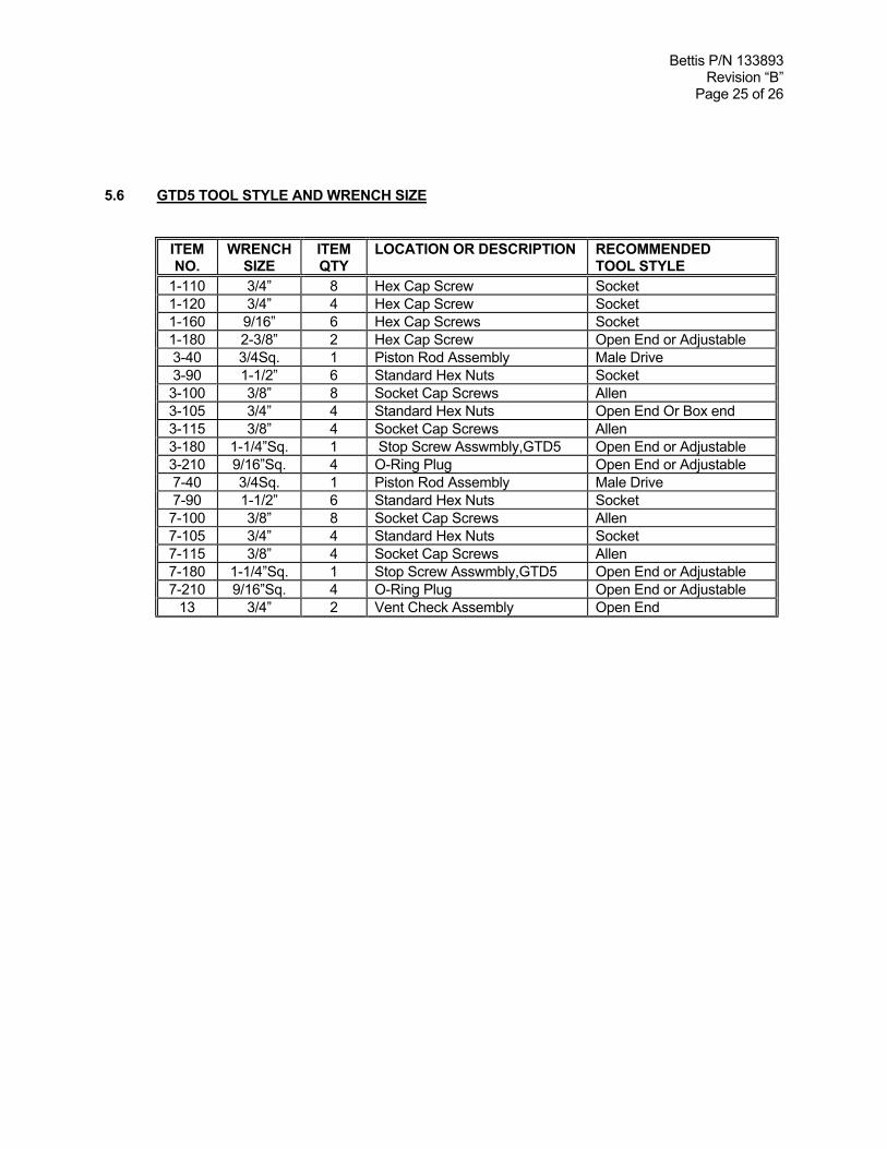
5.6 GTD5 TOOL STYLE AND WRENCH SIZE
ITEMNO.
WRENCHSIZE
ITEMQTY
LOCATION OR DESCRIPTION RECOMMENDEDTOOL STYLE
1-110 3/4” 8 Hex Cap Screw Socket1-120 3/4” 4 Hex Cap Screw Socket1-160 9/16” 6 Hex Cap Screws Socket1-180 2-3/8” 2 Hex Cap Screw Open End or Adjustable3-40 3/4Sq. 1 Piston Rod Assembly Male Drive3-90 1-1/2” 6 Standard Hex Nuts Socket3-100 3/8” 8 Socket Cap Screws Allen3-105 3/4” 4 Standard Hex Nuts Open End Or Box end3-115 3/8” 4 Socket Cap Screws Allen3-180 1-1/4”Sq. 1 Stop Screw Asswmbly,GTD5 Open End or Adjustable3-210 9/16”Sq. 4 O-Ring Plug Open End or Adjustable7-40 3/4Sq. 1 Piston Rod Assembly Male Drive7-90 1-1/2” 6 Standard Hex Nuts Socket7-100 3/8” 8 Socket Cap Screws Allen7-105 3/4” 4 Standard Hex Nuts Socket7-115 3/8” 4 Socket Cap Screws Allen7-180 1-1/4”Sq. 1 Stop Screw Asswmbly,GTD5 Open End or Adjustable7-210 9/16”Sq. 4 O-Ring Plug Open End or Adjustable
13 3/4” 2 Vent Check Assembly Open End
Bettis P/N 133893Revision “B”
Page 26 of 26
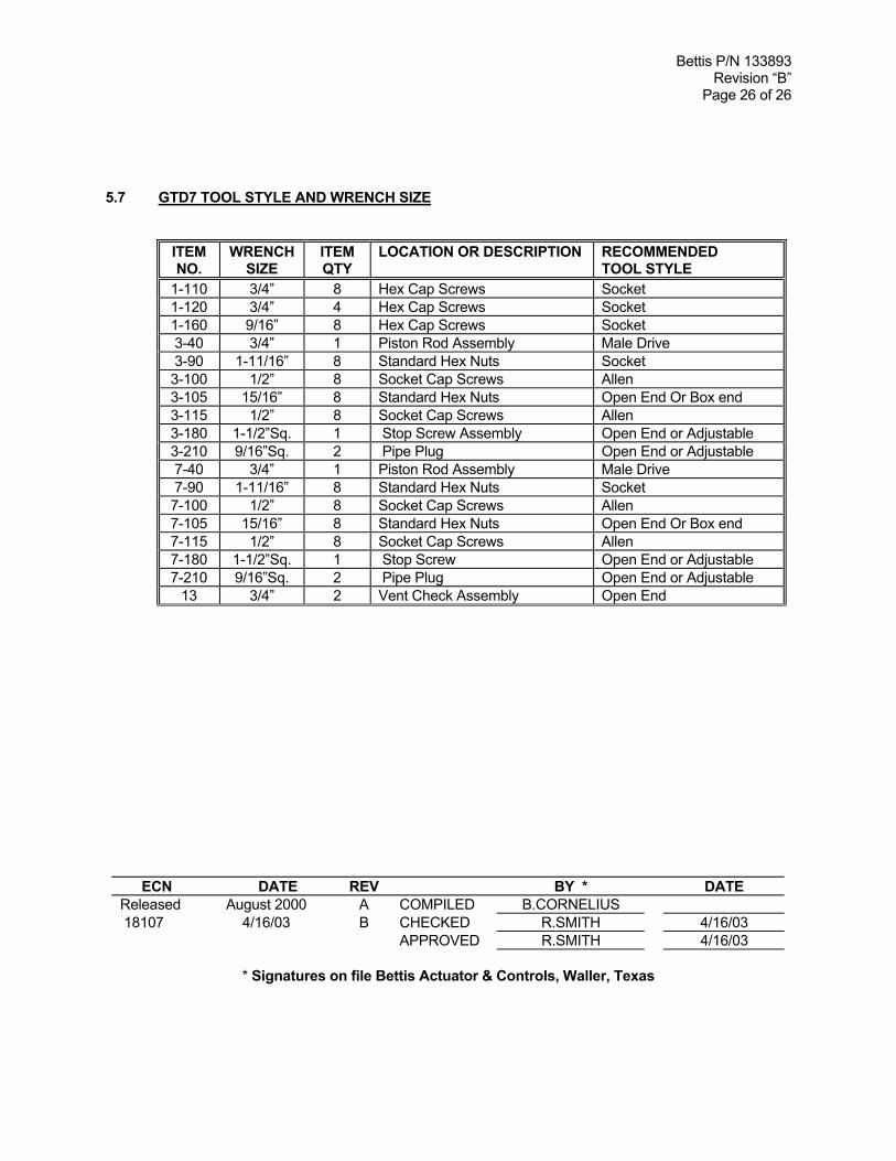
5.7 GTD7 TOOL STYLE AND WRENCH SIZE
ITEMNO.
WRENCHSIZE
ITEMQTY
LOCATION OR DESCRIPTION RECOMMENDEDTOOL STYLE
1-110 3/4” 8 Hex Cap Screws Socket1-120 3/4” 4 Hex Cap Screws Socket1-160 9/16” 8 Hex Cap Screws Socket3-40 3/4” 1 Piston Rod Assembly Male Drive3-90 1-11/16” 8 Standard Hex Nuts Socket3-100 1/2” 8 Socket Cap Screws Allen3-105 15/16” 8 Standard Hex Nuts Open End Or Box end3-115 1/2” 8 Socket Cap Screws Allen3-180 1-1/2”Sq. 1 Stop Screw Assembly Open End or Adjustable3-210 9/16”Sq. 2 Pipe Plug Open End or Adjustable7-40 3/4” 1 Piston Rod Assembly Male Drive7-90 1-11/16” 8 Standard Hex Nuts Socket7-100 1/2” 8 Socket Cap Screws Allen7-105 15/16” 8 Standard Hex Nuts Open End Or Box end7-115 1/2” 8 Socket Cap Screws Allen7-180 1-1/2”Sq. 1 Stop Screw Open End or Adjustable7-210 9/16”Sq. 2 Pipe Plug Open End or Adjustable
13 3/4” 2 Vent Check Assembly Open End
ECN DATE REV BY * DATEReleased August 2000 A COMPILED B.CORNELIUS 18107 4/16/03 B CHECKED R.SMITH 4/16/03
APPROVED R.SMITH 4/16/03
* Signatures on file Bettis Actuator & Controls, Waller, Texas


