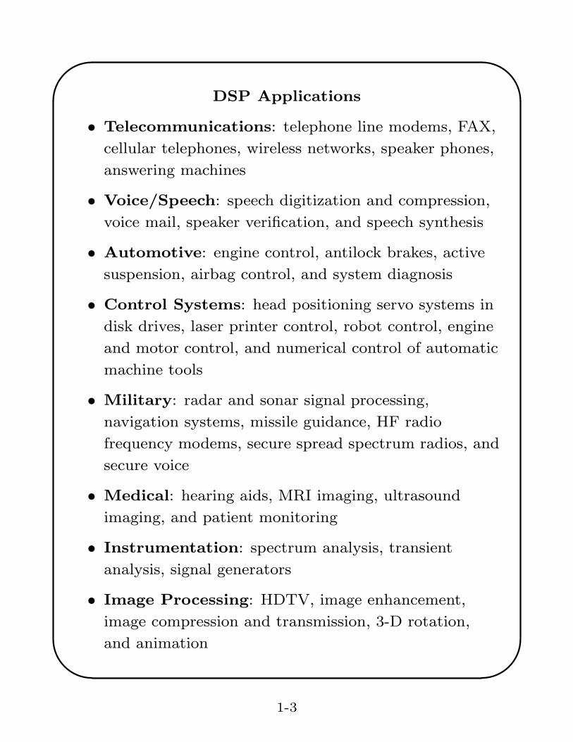
• Voice/Speech: speech digitization and compression,
voice mail, speaker verification, and speech synthesis
• Automotive: engine control, antilock brakes, active
suspension, airbag control, and system diagnosis
• Control Systems: head positioning servo systems in
disk drives, laser printer control, robot control, engine
and motor control, and numerical control of automatic
machine tools
• Military: radar and sonar signal processing,
navigation systems, missile guidance, HF radio
frequency modems, secure spread spectrum radios, and
secure voice
• Medical: hearing aids, MRI imaging, ultrasound
imaging, and patient monitoring
• Instrumentation: spectrum analysis, transient
analysis, signal generators
• Image Processing: HDTV, image enhancement,
image compression and transmission, 3-D rotation,
and animation
1-3
TMS320C6713 DSP Starter Kit
(DSK) Block DiagramSpectrum Digital, Inc
1-2 TMS320C6713 DSK Module Technical Reference
1.1 Key Features
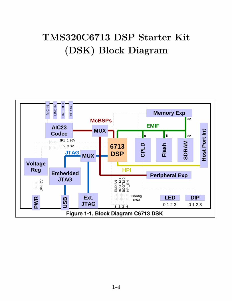
The C6713 DSK is a low-cost standalone development platform that enables users toevaluate and develop applications for the TI C67xx DSP family. The DSK also servesas a hardware reference design for the TMS320C6713 DSP. Schematics, logicequations and application notes are available to ease hardware development andreduce time to market.
The DSK comes with a full compliment of on-board devices that suit a wide variety ofapplication environments. Key features include:
• A Texas Instruments TMS320C6713 DSP operating at 225 MHz.
• An AIC23 stereo codec
• 16 Mbytes of synchronous DRAM
• 512 Kbytes of non-volatile Flash memory (256 Kbytes usable in default configuration)
• 4 user accessible LEDs and DIP switches
• Software board configuration through registers implemented in CPLD
• Configurable boot options
• Standard expansion connectors for daughter card use
• JTAG emulation through on-board JTAG emulator with USB host interface or external emulator
• Single voltage power supply (+5V)
Figure 1-1, Block Diagram C6713 DSK
Ext.JTAG
AIC23Codec
Hos
t Por
t Int
MUX
MUX
MIC
IN
LIN
E O
UT
HP
OU
T
LIN
E IN
Peripheral Exp
LED DIP
EMIF
HPI
McBSPs
JTAG
0 1 2 30 1 2 3
CPL
D
Memory Exp
PWR
USB
EmbeddedJTAG
JP1 1.26V
JP2 3.3V
END
IAN
BOO
TM 1
BOO
TM 0
6713DSP
SDR
AM
328
Flas
h
8
1 32
ConfigSW3
32
HPI
_EN
4
VoltageReg
JP4
5V
1-4
'
&
$
%
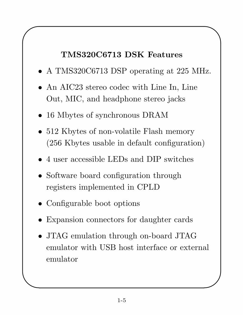
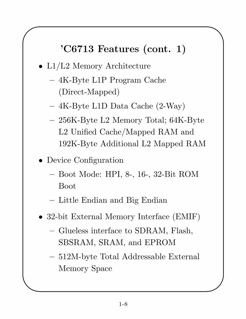
TMS320C6713 DSK Features
• A TMS320C6713 DSP operating at 225 MHz.
• An AIC23 stereo codec with Line In, LineOut, MIC, and headphone stereo jacks
• 16 Mbytes of synchronous DRAM
• 512 Kbytes of non-volatile Flash memory(256 Kbytes usable in default configuration)
• 4 user accessible LEDs and DIP switches
• Software board configuration throughregisters implemented in CPLD
• Configurable boot options
• Expansion connectors for daughter cards
• JTAG emulation through on-board JTAGemulator with USB host interface or externalemulator
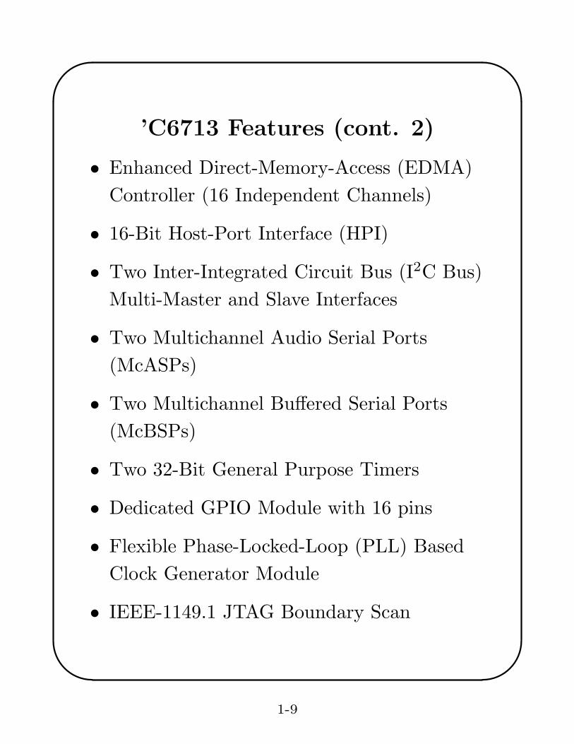
See TMS320C6000 CPU and Instruction Set, Reference Guide, SPRU189F forcomplete descriptions of instructions.
1-10
'
&
$
%
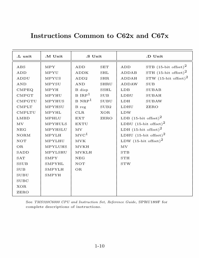
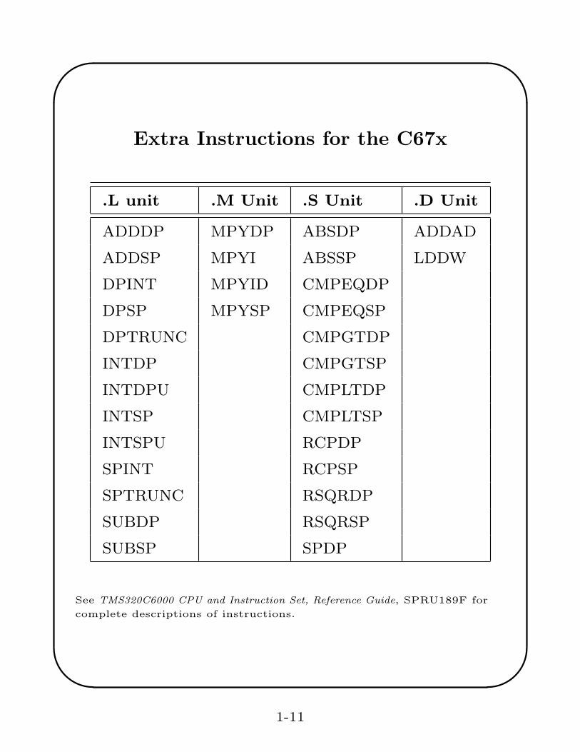
Extra Instructions for the C67x
.L unit .M Unit .S Unit .D Unit
ADDDP MPYDP ABSDP ADDAD
ADDSP MPYI ABSSP LDDW
DPINT MPYID CMPEQDP
DPSP MPYSP CMPEQSP
DPTRUNC CMPGTDP
INTDP CMPGTSP
INTDPU CMPLTDP
INTSP CMPLTSP
INTSPU RCPDP
SPINT RCPSP
SPTRUNC RSQRDP
SUBDP RSQRSP
SUBSP SPDP
See TMS320C6000 CPU and Instruction Set, Reference Guide, SPRU189F forcomplete descriptions of instructions.
1-11
'
&
$
%
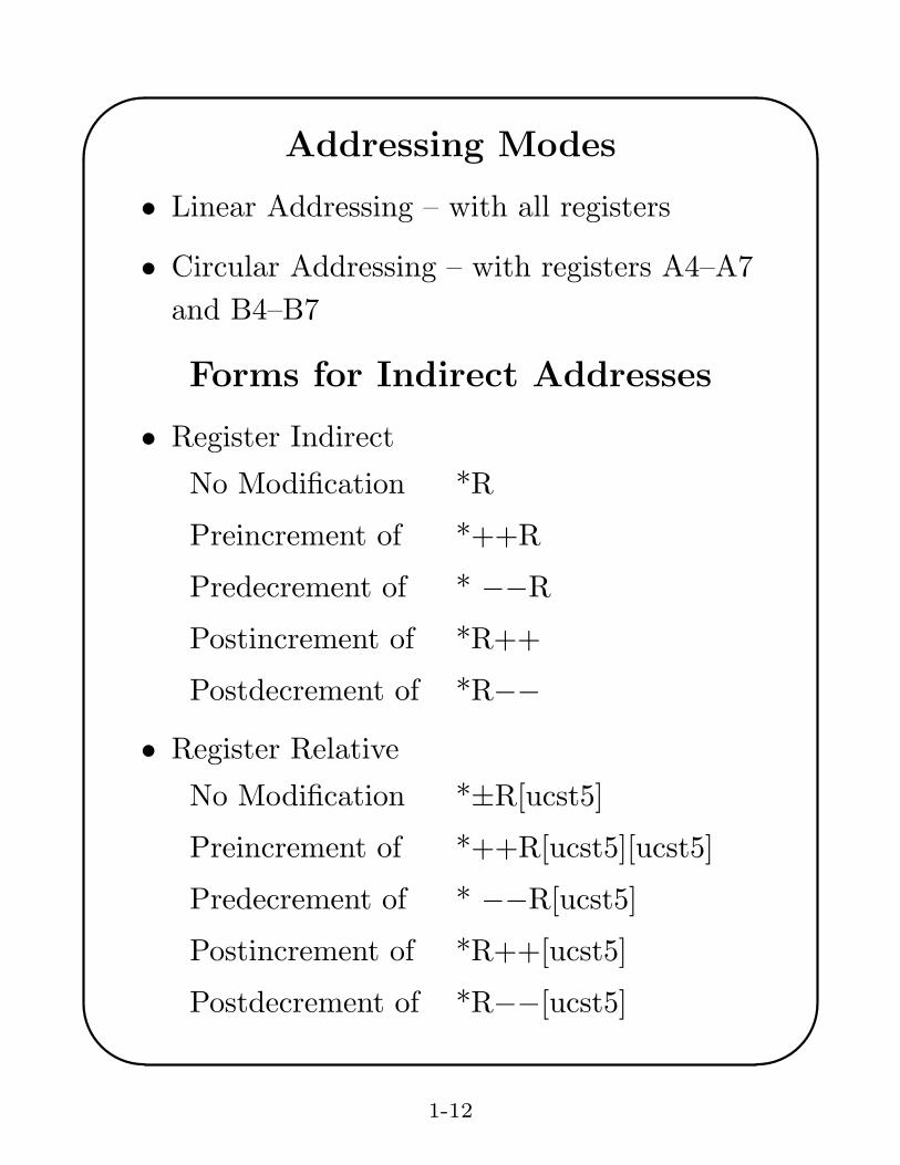
Addressing Modes
• Linear Addressing – with all registers
• Circular Addressing – with registers A4–A7and B4–B7
Forms for Indirect Addresses
• Register Indirect
No Modification *R
Preincrement of *++R
Predecrement of * −−R
Postincrement of *R++
Postdecrement of *R−−
• Register Relative
No Modification *±R[ucst5]
Preincrement of *++R[ucst5][ucst5]
Predecrement of * −−R[ucst5]
Postincrement of *R++[ucst5]
Postdecrement of *R−−[ucst5]
1-12
'
&
$
%
Forms for Indirect Addresses (cont.)
• Register Relative with 15-bit Constant Offset
No Modification *+B14/B15[ucst15]
• Base + Index
No Modification *±R[offsetR]
Preincrement of *++R[offsetR]
Predecrement of * −−R[offsetR]
Postincrement of *R++[offsetR]
Postdecrement of *R−−[offsetR]
Notes:
ucst5 = 5-bit unsigned integer constant
ucst15 = 15-bit unsigned integer constant
R = base register
offsetR = index register
Example: LDW .D1 *++A4[9], A1
Load a 32-bit word using functional unit D1 into
register A1 from the memory byte address:
contents of (A4) + 4× 9
1-13
'
&
$
%
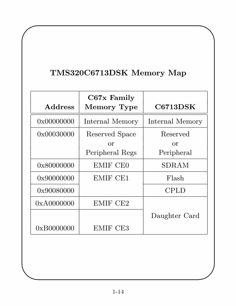
TMS320C6713DSK Memory Map
C67x Family
Address Memory Type C6713DSK
0x00000000 Internal Memory Internal Memory
0x00030000 Reserved Space Reserved
or or
Peripheral Regs Peripheral
0x80000000 EMIF CE0 SDRAM
0x90000000 EMIF CE1 Flash
0x90080000 CPLD
0xA0000000 EMIF CE2
Daughter Card
0xB0000000 EMIF CE3
1-14
'
&
$
%
Parallel Operations
• The instruction word for each functional unitis 32 bits long.
• Instructions are fetched 8 at a time consistingof 8× 32 = 256 bits. The group is called afetch packet. Fetch packets must start at anaddress that is a multiple of 8 32-bit words.
• Up to 8 instructions can be executed inparallel. Each must use a different functionalunit. Each group of parallel instructions iscalled an execute packet.
• The p-bit (bit 0) determines if an instructionexecutes in parallel with another. Theinstructions are scanned from the lowestaddress to the highest. If the p-bit ofinstruction i is 1, then instruction i + 1 isexecuted in parallel with instruction i. If it is0, instruction i + 1 is executed one cycle afterinstruction i.
1-15
'
&
$
%
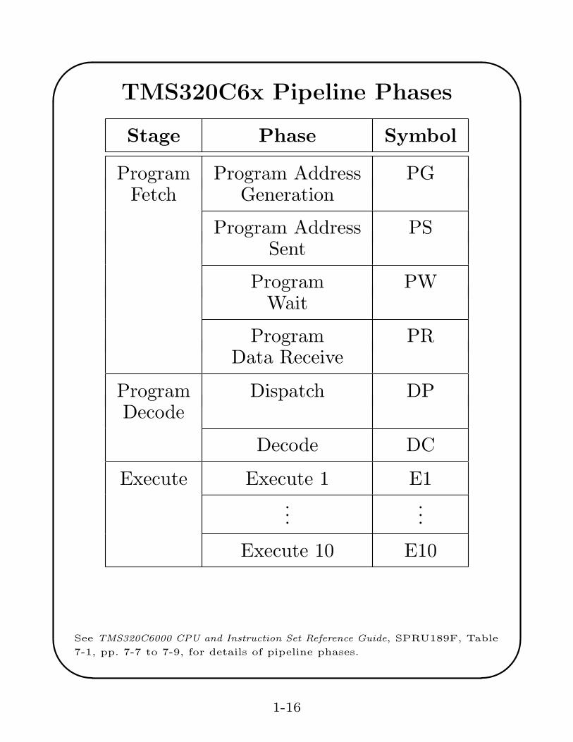
TMS320C6x Pipeline Phases
Stage Phase Symbol
Program Program Address PGFetch Generation
Program Address PSSent
Program PWWait
Program PRData Receive
Program Dispatch DPDecode
Decode DC
Execute Execute 1 E1...
...
Execute 10 E10
See TMS320C6000 CPU and Instruction Set Reference Guide, SPRU189F, Table7-1, pp. 7-7 to 7-9, for details of pipeline phases.
1-16
'
&
$
%
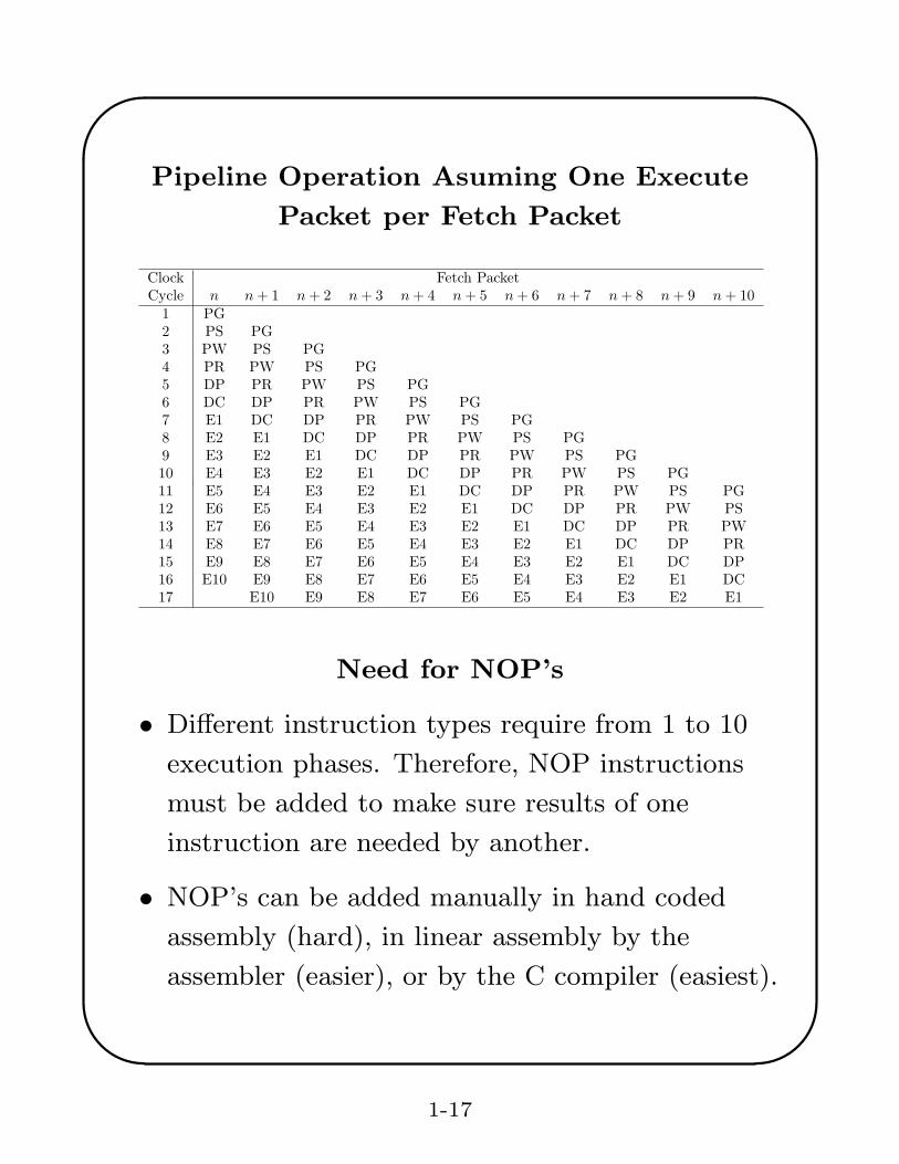
Pipeline Operation Asuming One Execute
Packet per Fetch Packet
Clock Fetch Packet
Cycle n n + 1 n + 2 n + 3 n + 4 n + 5 n + 6 n + 7 n + 8 n + 9 n + 10
1 PG
2 PS PG
3 PW PS PG
4 PR PW PS PG
5 DP PR PW PS PG
6 DC DP PR PW PS PG
7 E1 DC DP PR PW PS PG
8 E2 E1 DC DP PR PW PS PG
9 E3 E2 E1 DC DP PR PW PS PG
10 E4 E3 E2 E1 DC DP PR PW PS PG
11 E5 E4 E3 E2 E1 DC DP PR PW PS PG
12 E6 E5 E4 E3 E2 E1 DC DP PR PW PS
13 E7 E6 E5 E4 E3 E2 E1 DC DP PR PW
14 E8 E7 E6 E5 E4 E3 E2 E1 DC DP PR
15 E9 E8 E7 E6 E5 E4 E3 E2 E1 DC DP
16 E10 E9 E8 E7 E6 E5 E4 E3 E2 E1 DC
17 E10 E9 E8 E7 E6 E5 E4 E3 E2 E1
Need for NOP’s
• Different instruction types require from 1 to 10
execution phases. Therefore, NOP instructions
must be added to make sure results of one
instruction are needed by another.
• NOP’s can be added manually in hand coded
assembly (hard), in linear assembly by the
assembler (easier), or by the C compiler (easiest).
1-17
'
&
$
%
TI Software Tools
Code Composer Studio
• Create and edit source code
• Compile (cl6x.exe), assemble (asm6x.exe),and link (lnk6x.exe) programs using project“.pjt” files. (Actually, cl6x.exe is a shellprogram that can compile, assemble and link.)
• Build libraries with ar6x.exe
• Include a real-time operating system,DSP/BIOS, in the DSP code with real-timedata transfer (RTDX) between the PC andDSP
• Load programs into DSP, run programs,single step, break points, read memory andregisters, profile running programs, etc.
1-18
'
&
$
%
Building Programs
Assembler
Linker
Macrolibrary
Library ofobjectfiles
Assemblersource
COFFobjectfiles
Archiver
Macrosource
files
Archiver
C/C++ compiler
Library-buildutility
Run-Time-supportlibrary
C/C++source
files
ExecutableCOFF
file
Assembly-optimized
file
Assemblyoptimizer
Linear assembly
TMS320C6000 Optimizing Compiler User’s Guide (SPRU187I, April 2001,Figure 1-1, p. 1-2)
1-19
'
&
$
%
Other Software
• Microsoft Visual C++
• MATLAB
• Freeware Digital Filter DesignPrograms
– WINDOW.EXE
– REMEZ87.EXE
– IIR.EXE
– RASCOS.EXE
– SQRTRACO.EXE
• Plotting program GNUPLOT
• Standard MS Windows Programs likeMS Word and Excel
• SSH Terminal Program (PUTTY) andSSH File Transfer Program (WINSCP)
1-20
'
&
$
%
First Lab Session
The software utility you will use to generate and edit
source code, build executable DSP programs, and
load these programs into the ’C6713 DSK is called
Code Composer Studio.
For your first lab period:
1. Check out the hardware. The DSK has been
installed inside the PC case to keep it secure and
allow you access to the lab outside of regular class
hours. The important DSK connectors have been
brought out to the side of the PC case. The DSK
is connected to a USB port on the motherboard
and the power supply has been brought out to an
external plug.
Find the stereo connectors for the A/D and D/A
converters on the case. Notice that the connectors
are labeled MIC IN, LINE IN, LINE OUT, and
HEADPHONE. The MIC IN input is for low
voltage signals. For ENEE 428 you should use
only the LINE IN and LINE OUT connectors.
1-21
'
&
$
%
First Lab Session (cont.)
2. Work through the Code Composer tutorial to
learn how to build a project, run programs, do file
I/O, and display signal graphs. If you finish these
items, do more of the tutorial. You should also
browse through the online manuals for the CPU,
peripherals, and software development tools.
These tasks as well as getting key card access and
computer accounts should fill up the first lab
session.
Remember that this class is not a race and you
should work carefully and understand exactly
what you are doing at each step.
No lab report is required for this experiment.
1-22
'
&
$
%
Code Composer Studio Tutorial
Please do not modify or work in the
C:\CCStudio v3.1 or C:\c6713 directories. Use
a directory in your workspace on the PC or
network server.
1. Double click on the Code Composer icon named
C6713 DSK
CCStudioon the desktop.
You will probably see a message from CCS that
no target is connected. Click on Debug on the
menu bar and then on Connect.
2. Click on Help on the CC menu bar.
3. Select Tutorial and then Code Composer Studio
IDE.
4. Work through as much of the tutorial as you can
during lab. Be sure to learn how to
• create a project file
• build and run a program
• use break points and watch windows
• do file I/O and display graphs
1-23
'
&
$
%
Building Programs from DOS
If you do not like to use the Code Composerproject environment, you can use the TI codedevelopment tools from a DOS window. The shellprogram, CL6X.EXE, compiles, assembles, andlinks programs. The general format for invokingthis shell is
cl6x [-compiler options] [filenames]
[-z [link options]]
See the TMS320C6000 Floating-Point DSPOptimizing Compiler User’s Guide (SPRU1871)for details. The entry [filenames] is a list ofsource filenames. Filenames that have noextension are automatically considered to havethe .c extension and to be C source code.Filenames with the .asm extension are consideredto be assembly language source code and areassembled. Everything to the right of the -zoption applies only to the linker.
1-24
'
&
$
%
Hardware and Software References
Many TI documents describing theTMS320C6713 DSK, Code Composer Studio, theTMS320C6000 DSP series, and TI C compilertools were loaded on the PC’s C drive when theDSK software was installed. You can access thesemanuals by starting Code Composer and clickingon the Help button and choosing the desiredoption. In particular, you will find the followingdocuments very useful:
1. TMS320C6000 CPU and Instruction SetReference Guide, SPRU189F, October 2000.
2. TMS320C6000 Periperals Reference Guide,SPRU190D, March 2001.
3. TMS320C6000 Chip Support Library APIReference Guide, SPRU401b, April 2001.
4. TMS320C6000 Optimizing Compiler User’sGuide, SPRU187I, April 2001