45
BFC21103 Hydraulics Chapter 6. Hydraulic Machinery Tan Lai Wai, Wan Afnizan & Zarina Md Ali [email protected] Updated: September 2014

BFC21103 Hydraulics
Chapter 6. Hydraulic Machinery
Tan Lai Wai, Wan Afnizan & Zarina Md [email protected]
Updated: September 2014
Learning Outcomes
At the end of this chapter, students should be able to:
i. Calculate the efficiency of pump and turbine;
ii. Determine the discharge and energy head of pumps in parallel and series; and
iii. Carry out similitude analysis between model and prototype of pump and turbine.
BFC21103 Hydraulics Tan et al. ([email protected])
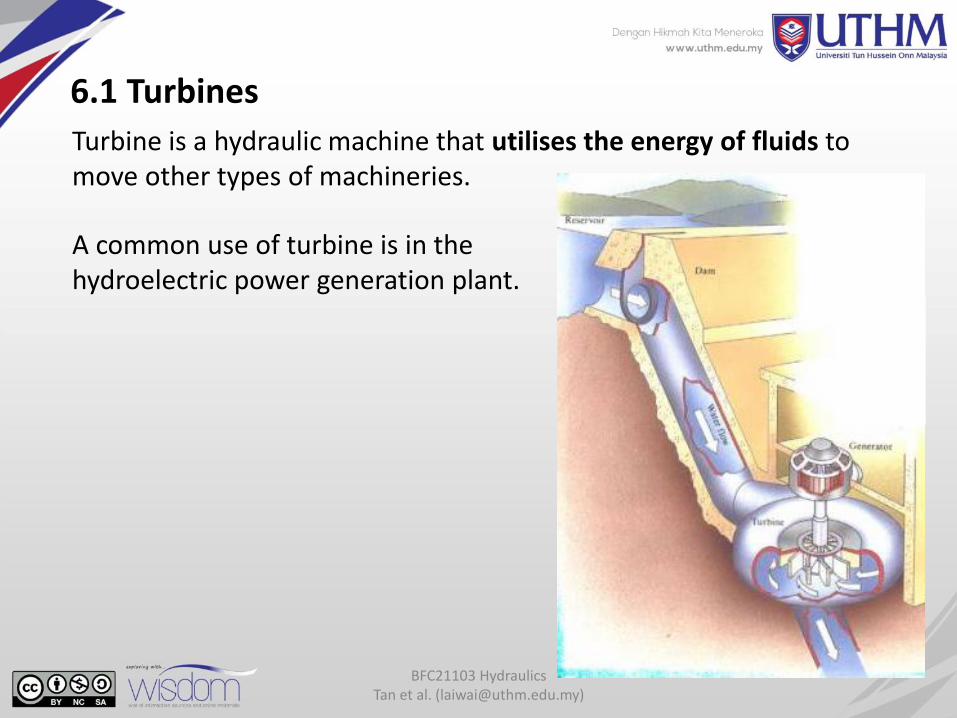
6.1 Turbines
BFC21103 Hydraulics Tan et al. ([email protected])
Turbine is a hydraulic machine that utilises the energy of fluids to move other types of machineries.
A common use of turbine is in the hydroelectric power generation plant.
BFC21103 Hydraulics Tan et al. ([email protected])
Classification of Turbines
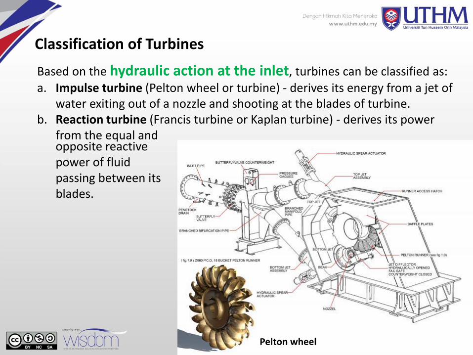
Based on the hydraulic action at the inlet, turbines can be classified as:
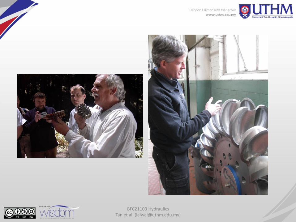
a. Impulse turbine (Pelton wheel or turbine) - derives its energy from a jet of water exiting out of a nozzle and shooting at the blades of turbine.
b. Reaction turbine (Francis turbine or Kaplan turbine) - derives its power from the equal and
Pelton wheel
opposite reactive power of fluid passing between its blades.

BFC21103 Hydraulics Tan et al. ([email protected])
Based on the direction of flow through the runner, turbines can be
classified as:a. Tangential flow turbine (Pelton wheel)b. Radial flow turbine (Francis turbine, Thomsen and Girard turbines)c. Axial flow turbine (Kaplan turbine)d. Mixed flow turbine (modern Francis turbine)
Pelton wheel Francis turbine Kaplan turbine
Radial flow turbine
Mixed flow turbine
BFC21103 Hydraulics Tan et al. ([email protected])
Based on the head of water H, turbines can be classified as:
a. High head turbine (Pelton wheel, H > 250 m)b. Medium head turbine (modern Francis turbine, 60 m H 250 m)c. Low head turbine (Kaplan turbine, H < 60 m)
Pelton wheel is suitable for medium head and low discharge.
Francis turbines are effective on a very wide range of heads (medium head) and are very much used in spite of their relatively high cost. Usually work in radial flow but also in mixed flow.
A Kaplan (propeller) turbine is an axial flow machine with its runner confined in a closed conduit. A propeller turbine is often set on a vertical axis, and can also be set on a horizontal axis or a slightly inclined axis. A propeller turbine is suitable for operation with low head and high discharge.
BFC21103 Hydraulics Tan et al. ([email protected])
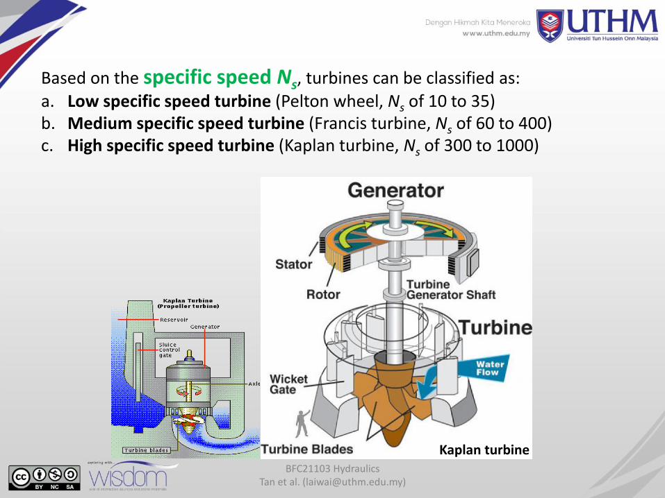
Based on the specific speed Ns, turbines can be classified as:
a. Low specific speed turbine (Pelton wheel, Ns of 10 to 35)b. Medium specific speed turbine (Francis turbine, Ns of 60 to 400)c. High specific speed turbine (Kaplan turbine, Ns of 300 to 1000)
Kaplan turbine
BFC21103 Hydraulics Tan et al. ([email protected])
6.2 Pumps
A pump is a hydraulic machine which supplies energy to fluid in certain operation, e.g. in water distribution system.
Based on the mode of action of conversion of mechanical energyinto hydraulic energy, pumps are classified as:
a. rotadynamic pumps (centrifugal pump) and
b. positive displacement pumps.
BFC21103 Hydraulics Tan et al. ([email protected])
Rotadynamic pump
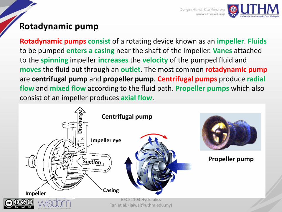
Rotadynamic pumps consist of a rotating device known as an impeller. Fluidsto be pumped enters a casing near the shaft of the impeller. Vanes attached to the spinning impeller increases the velocity of the pumped fluid and moves the fluid out through an outlet. The most common rotadynamic pump are centrifugal pump and propeller pump. Centrifugal pumps produce radial flow and mixed flow according to the fluid path. Propeller pumps which also consist of an impeller produces axial flow.
Propeller pump
Centrifugal pump
ImpellerCasing
Impeller eye
Dis
char
ge
BFC21103 Hydraulics Tan et al. ([email protected])
6.2 Power and Efficiency of Pump
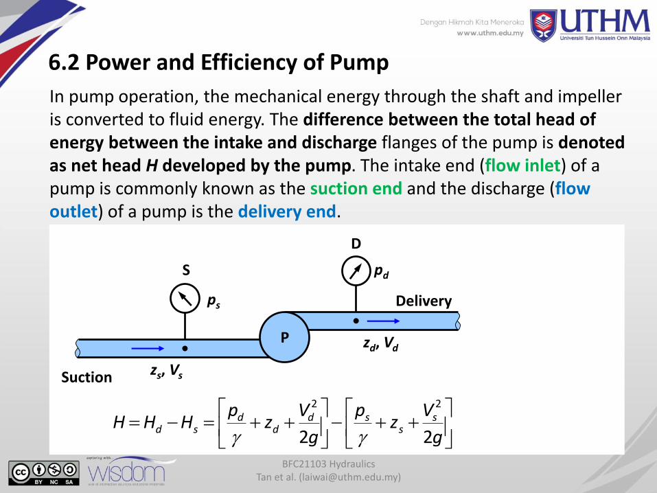
In pump operation, the mechanical energy through the shaft and impeller is converted to fluid energy. The difference between the total head of energy between the intake and discharge flanges of the pump is denoted as net head H developed by the pump. The intake end (flow inlet) of a pump is commonly known as the suction end and the discharge (flow outlet) of a pump is the delivery end.
g
Vz
p
g
Vz
pHHH s
ssd
dd
sd22
22
Delivery
Suction
P
D
S
ps
pd
zd, Vd
zs, Vs
BFC21103 Hydraulics Tan et al. ([email protected])
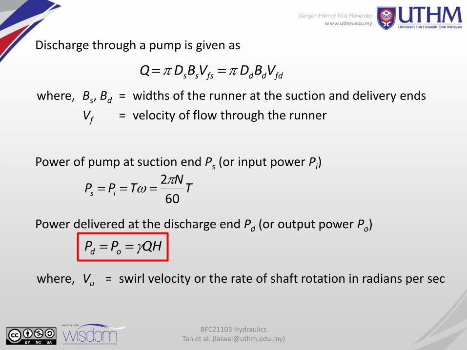
Discharge through a pump is given as
fdddfsss VBDVBDQ
where, Bs, Bd = widths of the runner at the suction and delivery ends
Vf = velocity of flow through the runner
Power of pump at suction end Ps (or input power Pi)
TN
TPP is60
2
Power delivered at the discharge end Pd (or output power Po)
QHPP od
where, Vu = swirl velocity or the rate of shaft rotation in radians per sec
BFC21103 Hydraulics Tan et al. ([email protected])
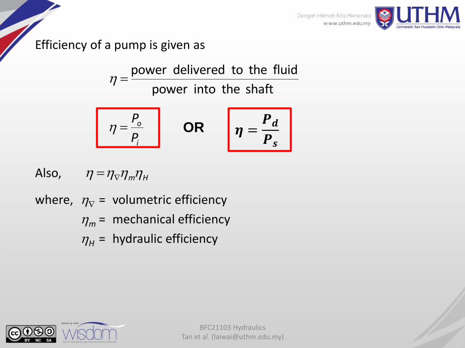
Efficiency of a pump is given as
shaft the into power
fluid the to delivered power
P
P
i
o
Hm Also,
where, = volumetric efficiency
m = mechanical efficiency
H = hydraulic efficiency
OR 𝜼 =𝑷𝒅
𝑷𝒔
BFC21103 Hydraulics Tan et al. ([email protected])
A centrifugal pump is needed to supply 23 m3/s of water for a city. This operation will utilise a net head H = 20 m and specific speed N = 450 rpm. If the inflow power Ps is 5000 kW and density of water is 1000 kg/m3 at 5C, calculate:
(a) Output power Pd
(b) Overall efficiency of the pump
Activity 6.1
BFC21103 Hydraulics Tan et al. ([email protected])
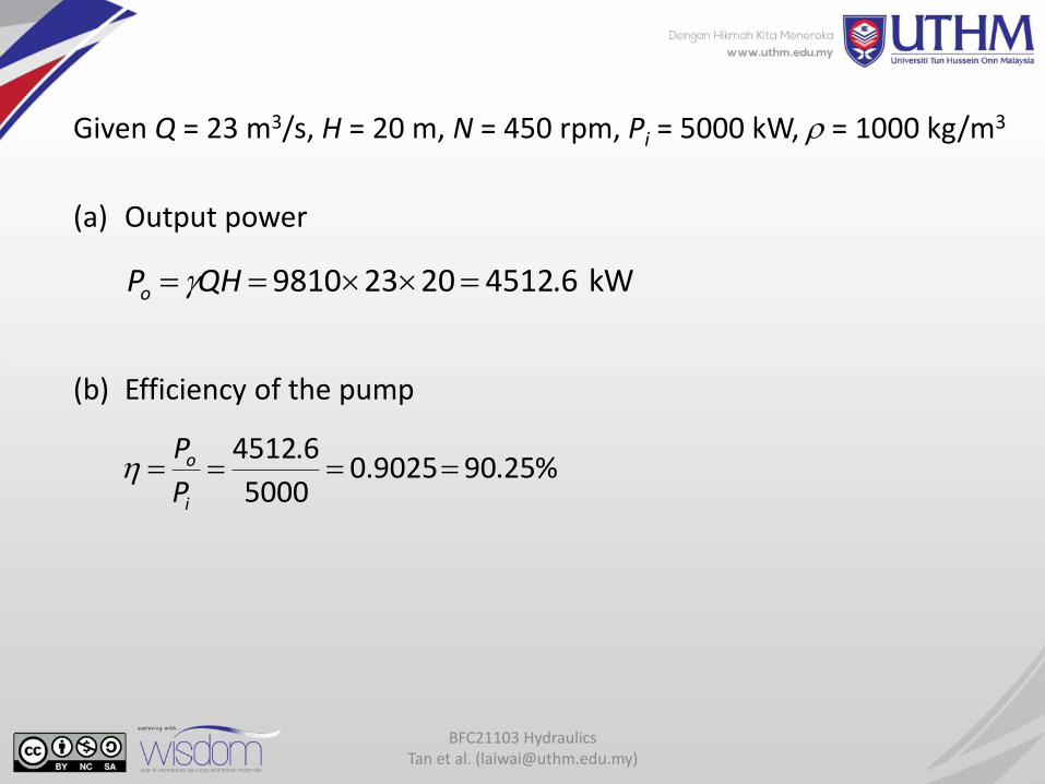
Given Q = 23 m3/s, H = 20 m, N = 450 rpm, Pi = 5000 kW, = 1000 kg/m3
(a) Output power
kW 6.451220239810 QHPo
(b) Efficiency of the pump
%25.909025.05000
6.4512
P
P
i
o
BFC21103 Hydraulics Tan et al. ([email protected])
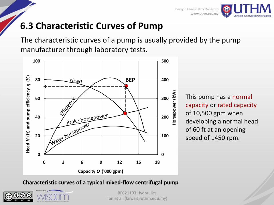
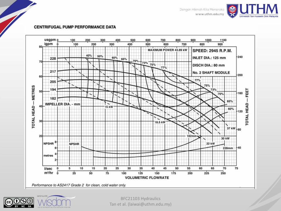
6.3 Characteristic Curves of Pump
The characteristic curves of a pump is usually provided by the pump manufacturer through laboratory tests.
Characteristic curves of a typical mixed-flow centrifugal pump
0
20
40
60
80
100
0 3 6 9 12 15 18
Capacity Q ('000 gpm)
Hea
d H
(ft
) an
d p
um
p e
ffic
ien
cy
(%
)
0
100
200
300
400
500
Ho
rsep
ow
er (
kW)
This pump has a normal capacity or rated capacityof 10,500 gpm when developing a normal head of 60 ft at an opening speed of 1450 rpm.
BEP
BFC21103 Hydraulics Tan et al. ([email protected])
Relationship between input power Pi, efficiency and head H starts when intake valve is closed, and the impeller spins until pressure at output increase to the maximum head (shut-off head). When the valve is open, water will flow through the pipe and the head of pump will decrease. With addition of flow rate, the pump efficiency will increase until it reach a maximum and then decrease to end of operation.
Intersection between head and power corresponds to the point of optimum efficiency is the best point to use pump (known as the best efficiency point, BEP).
BFC21103 Hydraulics Tan et al. ([email protected])
BFC21103 Hydraulics Tan et al. ([email protected])
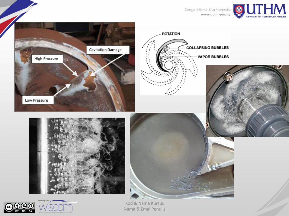
6.4 Cavitation
An important factor in the satisfactory operation of a pump is the avoidance of cavitation, both for good efficiency and for prevention of impeller damage.
As liquid passes through the impeller of a pump, there is a change in pressure. If the absolute pressure of the liquid drops to the vapour pressure, cavitation will occur. The region of vaporization hinders the flow and places a limit on the capacity of the pump.
As the fluid moves further into a region of higher pressure, the bubbles collapse and the implosion of the bubbles may cause pitting of the impeller.
Cavitation is most likely to occur near the point of discharge (periphery) of radial flow and mixed flow impellers, where velocities are highest. It may also occur on the suction side of the impeller, where the pressures are the lowest.
Kod & Nama Kursus Nama & EmailPenulis
BFC21103 Hydraulics Tan et al. ([email protected])
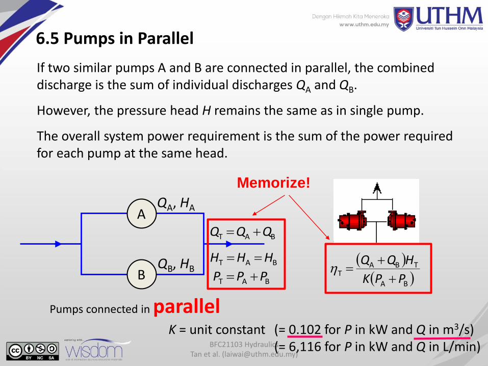
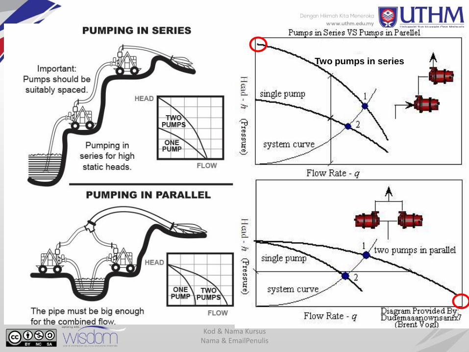
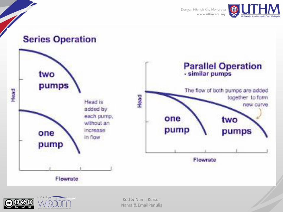
6.5 Pumps in Parallel
If two similar pumps A and B are connected in parallel, the combined discharge is the sum of individual discharges QA and QB.
However, the pressure head H remains the same as in single pump.
The overall system power requirement is the sum of the power required for each pump at the same head.
A
B
QA, HA
QB, HB
BAT QQQ
BAT HHH
BAT PPP
BA
TBAT
PPK
HQQ
K = unit constant (= 0.102 for P in kW and Q in m3/s) (= 6,116 for P in kW and Q in L/min)
Memorize!
Pumps connected in parallel
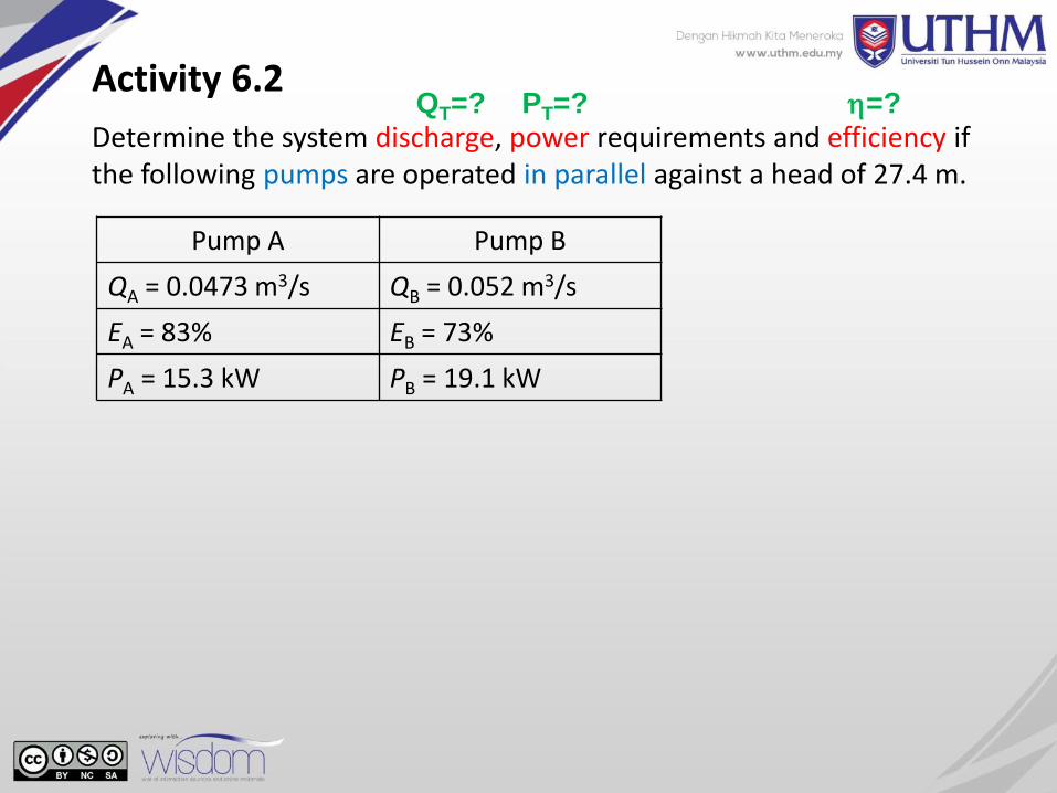
Determine the system discharge, power requirements and efficiency if the following pumps are operated in parallel against a head of 27.4 m.
Activity 6.2
Pump A Pump B
QA = 0.0473 m3/s QB = 0.052 m3/s
EA = 83% EB = 73%
PA = 15.3 kW PB = 19.1 kW
QT=? PT=? =?
BFC21103 Hydraulics Tan et al. ([email protected])
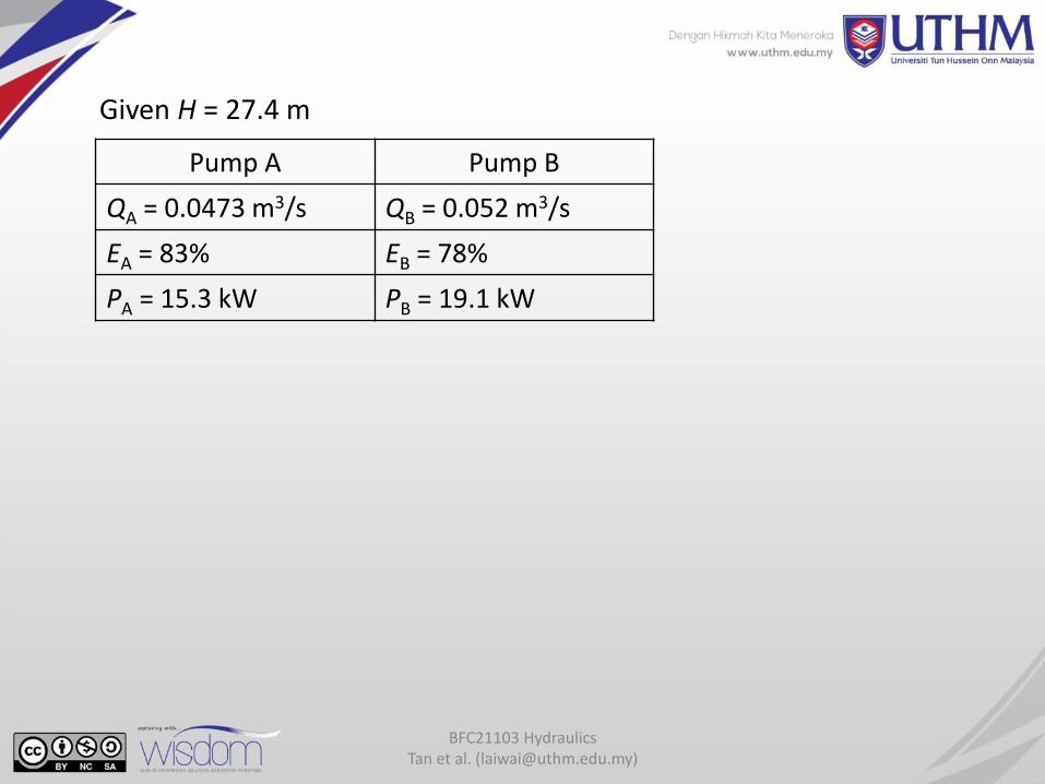
Given H = 27.4 m
Pump A Pump B
QA = 0.0473 m3/s QB = 0.052 m3/s
EA = 83% EB = 78%
PA = 15.3 kW PB = 19.1 kW
BFC21103 Hydraulics Tan et al. ([email protected])
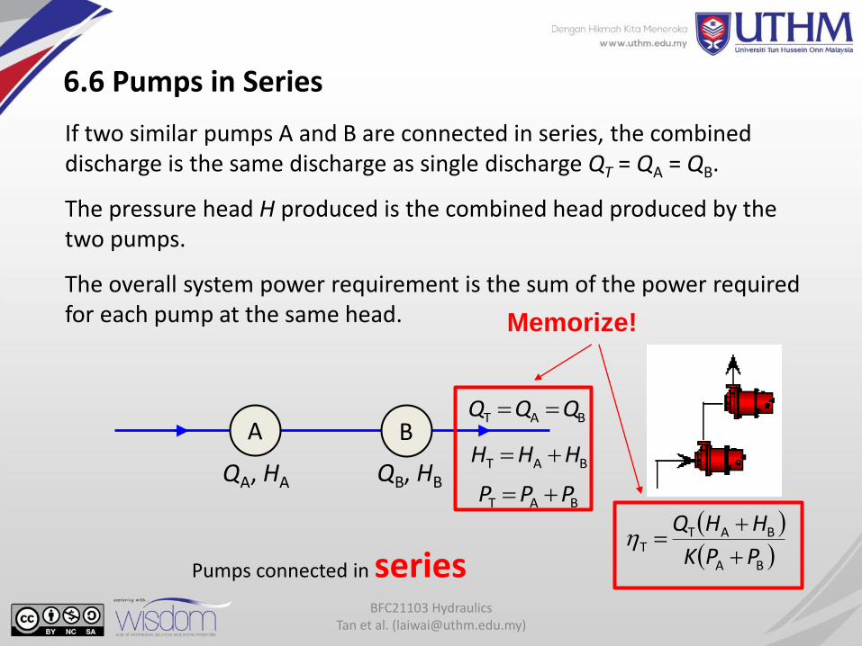
6.6 Pumps in Series
If two similar pumps A and B are connected in series, the combined discharge is the same discharge as single discharge QT = QA = QB.
The pressure head H produced is the combined head produced by the two pumps.
The overall system power requirement is the sum of the power required for each pump at the same head.
A B
QA, HA QB, HB
BAT QQQ
BAT HHH
Pumps connected in series
BAT PPP
BA
BATT
PPK
HHQ
Memorize!
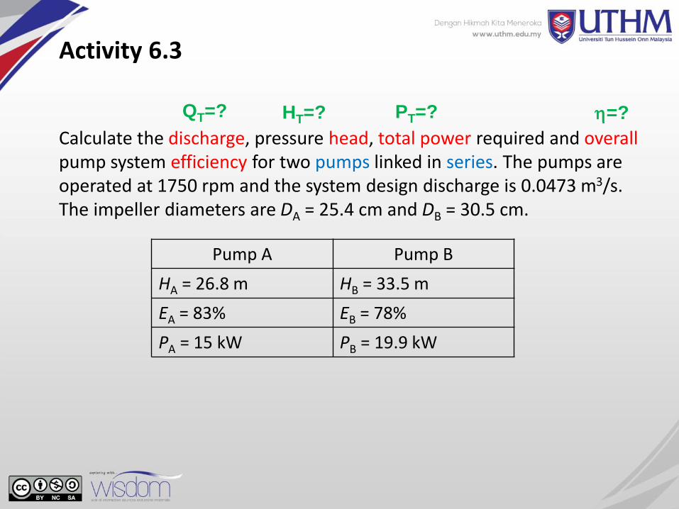
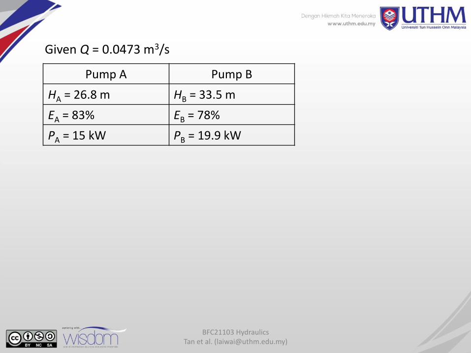
Calculate the discharge, pressure head, total power required and overallpump system efficiency for two pumps linked in series. The pumps are operated at 1750 rpm and the system design discharge is 0.0473 m3/s. The impeller diameters are DA = 25.4 cm and DB = 30.5 cm.
Activity 6.3
Pump A Pump B
HA = 26.8 m HB = 33.5 m
EA = 83% EB = 78%
PA = 15 kW PB = 19.9 kW
QT=? PT=? =?HT=?
BFC21103 Hydraulics Tan et al. ([email protected])
Given Q = 0.0473 m3/s
Pump A Pump B
HA = 26.8 m HB = 33.5 m
EA = 83% EB = 78%
PA = 15 kW PB = 19.9 kW
Kod & Nama Kursus Nama & EmailPenulis
Two pumps in series
Kod & Nama Kursus Nama & EmailPenulis
BFC21103 Hydraulics Tan et al. ([email protected])
6.7 Similitude for Pumps and Turbines
Similarity laws help to interpret the results of model studies. The relation between model and prototype is classified into 3, i.e.:
a. Geometric similarity - prototype and model have identical shapes but differ in size.
b. Kinematic similarity - ratio of velocities at all corresponding points in flow are the same and involve length and time.
c. Dynamic similarity - two systems have dynamic similarity if, in addition to dynamic similarity, corresponding forces are in the sameratio in both.
BFC21103 Hydraulics Tan et al. ([email protected])
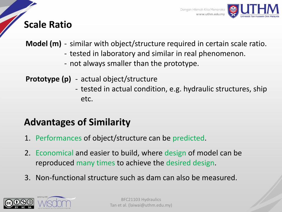
Scale Ratio
Model (m) - similar with object/structure required in certain scale ratio.- tested in laboratory and similar in real phenomenon.- not always smaller than the prototype.
Prototype (p) - actual object/structure- tested in actual condition, e.g. hydraulic structures, ship
etc.
1. Performances of object/structure can be predicted.
2. Economical and easier to build, where design of model can be reproduced many times to achieve the desired design.
3. Non-functional structure such as dam can also be measured.
Advantages of Similarity
BFC21103 Hydraulics Tan et al. ([email protected])
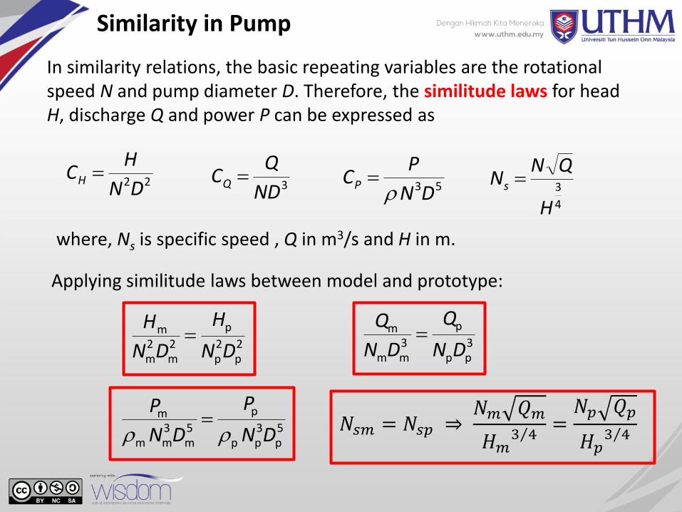
Similarity in Pump
In similarity relations, the basic repeating variables are the rotational speed N and pump diameter D. Therefore, the similitude laws for head H, discharge Q and power P can be expressed as
22DN
HCH 3ND
QCQ 53DN
PCP
2p
2p
p
2m
2m
m
DN
H
DN
H
Applying similitude laws between model and prototype:
3pp
p
3mm
m
DN
Q
DN
Q
5p
3pp
p
5m
3mm
m
DN
P
DN
P
4
3
H
QNNs
where, Ns is specific speed , Q in m3/s and H in m.
𝑁𝑠𝑚 = 𝑁𝑠𝑝 ⇒𝑁𝑚 𝑄𝑚
𝐻𝑚 3 4
=𝑁𝑝 𝑄𝑝
𝐻𝑝 3 4
BFC21103 Hydraulics Tan et al. ([email protected])
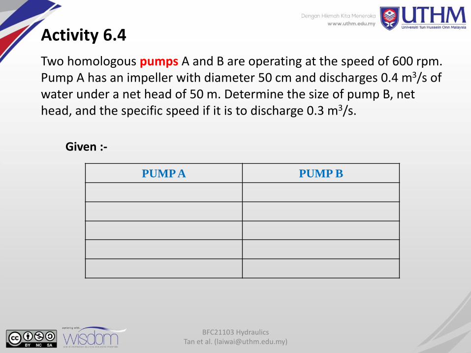
Two homologous pumps A and B are operating at the speed of 600 rpm. Pump A has an impeller with diameter 50 cm and discharges 0.4 m3/s of water under a net head of 50 m. Determine the size of pump B, net head, and the specific speed if it is to discharge 0.3 m3/s.
Activity 6.4
Given :-
PUMP A PUMP B
BFC21103 Hydraulics Tan et al. ([email protected])
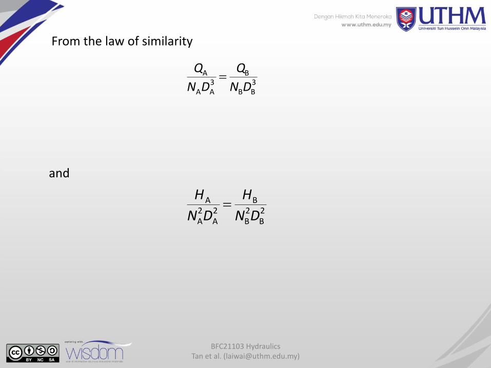
From the law of similarity
3BB
B3AA
A
DN
Q
DN
Q
and
2B
2B
B2A
2A
A
DN
H
DN
H
BFC21103 Hydraulics Tan et al. ([email protected])
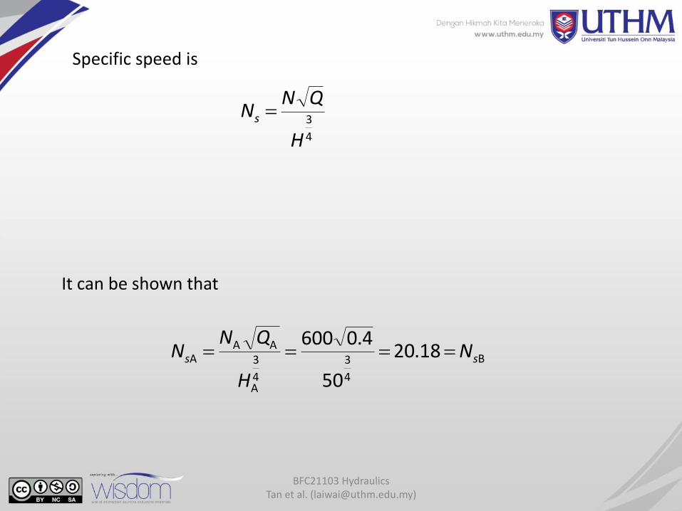
Specific speed is
4
3
H
QNNs
B
4
3
4
3
A
AAA 18.20
50
4.0600ss N
H
QNN
It can be shown that
BFC21103 Hydraulics Tan et al. ([email protected])
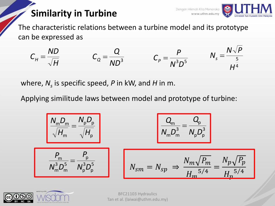
Similarity in Turbine
The characteristic relations between a turbine model and its prototype can be expressed as
H
NDCH 3ND
QCQ 53DN
PCP
p
pp
m
mm
H
DN
H
DN
Applying similitude laws between model and prototype of turbine:
3pp
p
3mm
m
DN
Q
DN
Q
5p
3p
p
5m
3m
m
DN
P
DN
P
where, Ns is specific speed, P in kW, and H in m.
4
5
H
PNNs
𝑁𝑠𝑚 = 𝑁𝑠𝑝 ⇒𝑁𝑚 𝑃𝑚
𝐻𝑚 5 4
=𝑁𝑝 𝑃𝑝
𝐻𝑝 5 4
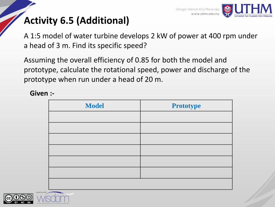
A 1:5 model of water turbine develops 2 kW of power at 400 rpm under a head of 3 m. Find its specific speed?
Assuming the overall efficiency of 0.85 for both the model and prototype, calculate the rotational speed, power and discharge of the prototype when run under a head of 20 m.
Activity 6.5 (Additional)
Given :-
Model Prototype
BFC21103 Hydraulics Tan et al. ([email protected])
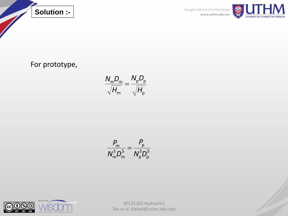
For prototype,
p
pp
m
mm
H
DN
H
DN
5p
3p
p
5m
3m
m
DN
P
DN
P
Solution :-
BFC21103 Hydraulics Tan et al. ([email protected])
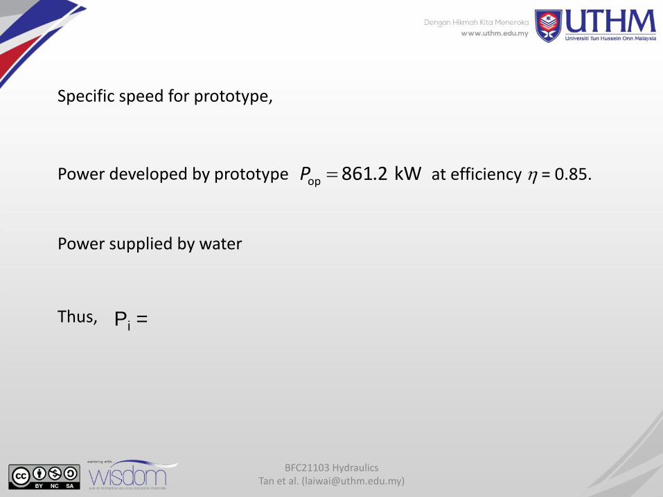
Specific speed for prototype,
Power developed by prototype kW 2.861op P at efficiency = 0.85.
Power supplied by water
Thus, Pi =
BFC21103 Hydraulics Tan et al. ([email protected])
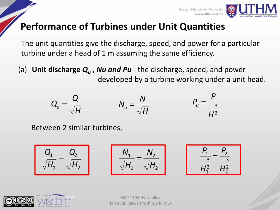
Performance of Turbines under Unit Quantities
The unit quantities give the discharge, speed, and power for a particular turbine under a head of 1 m assuming the same efficiency.
(a) Unit discharge Qu , Nu and Pu - the discharge, speed, and power developed by a turbine working under a unit head.
Between 2 similar turbines,
H
QQu
2
2
1
1
H
Q
H
Q
H
NNu
2
3
H
PPu
2
2
1
1
H
N
H
N
2
3
2
2
2
3
1
1
H
P
H
P
BFC21103 Hydraulics Tan et al. ([email protected])
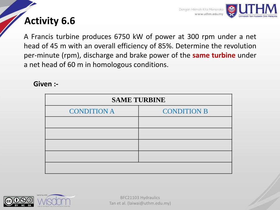
A Francis turbine produces 6750 kW of power at 300 rpm under a nethead of 45 m with an overall efficiency of 85%. Determine the revolutionper-minute (rpm), discharge and brake power of the same turbine undera net head of 60 m in homologous conditions.
Activity 6.6
Given :-
SAME TURBINE
CONDITION A CONDITION B
BFC21103 Hydraulics Tan et al. ([email protected])
Assignment #6
Q1. What are the functions of hydraulic pumps and turbines?
Q2. 0.5 m3/s of water is to be pumped to a total head of 250 m. How many pumps connected in series should be required if each pump has a specific speed of 35 and speed of 1500 rpm.
Q3. A turbine develops 8500 kW under a head of 18 m at 150 rpm. Calculate(a) specific speed(b) normal speed under a head of 25 m(c) output under a head of 25 m
BFC21103 Hydraulics Tan et al. ([email protected])
Q4. A centrifugal pump has an impeller of 200 mm with capacity 400 L/s at speed 1200 rpm against a head of 12 m. Calculate the speed and head of a geometrically similar pump with impeller diameter of 300 mm which is required to deliver 700 L/s.
Q5. A turbine is to operate under a head of 28 m at 185 rpm. The discharge is 10 m3/s. If the efficiency is 87%, determine the performance (N, Q, P) of the turbine under a head of 20 m.
- End of Question -