469
Cinterion ® BGS5 AT Command Set Version: 02.000 DocId: BGS5_ATC_V02.000

Cinterion® BGS5 AT Command Set
Version: 02.000DocId: BGS5_ATC_V02.000

Cinterion® BGS5 AT Command Set
t BGS5_ATC_V02.000 20/05/11Public / Released
GENERAL NOTE THIS DOCUMENT CONTAINS INFORMATION ON THALES DIS AIS DEUTSCHLAND GMBH (“THALES“) PRODUCTS. THALES RESERVES THE RIGHT TO MAKE CHANGES TO THE PRODUCTS DESCRIBED HEREIN. THE SPECIFICATIONS IN THIS DOCUMENT ARE SUBJECT TO CHANGE AT THE DISCRETION OF THALES. THE PRODUCT AND THIS DOCUMENT ARE PROVIDED ON AN "AS IS" BASIS ONLY AND MAY CONTAIN DEFICIENCIES OR INADEQUACIES. THALES DOES NOT ASSUME ANY LIABILITY FOR INFORMATION PROVIDED IN THE DOCUMENT OR ARISING OUT OF THE APPLICATION OR USE OF ANY PRODUCT DESCRIBED HEREIN.
THALES GRANTS A NON-EXCLUSIVE RIGHT TO USE THE DOCUMENT. THE RECIPIENT SHALL NOT COPY, MODIFY, DISCLOSE OR REPRODUCE THE DOCUMENT EXCEPT AS SPECIFICALLY AUTHORIZED BY THALES.
Copyright © 2020, THALES DIS AIS Deutschland GmbH
Trademark NoticeThales, the Thales logo, are trademarks and service marks of Thales and are registered in certain countries.
Microsoft and Windows are either registered trademarks or trademarks of Microsoft Corporation in the United States and/or other countries. All other registered trademarks or trademarks mentioned in this document are property of their respective owners.
Page 2 of 469
Document Name: Cinterion® BGS5 AT Command Set
Version: 02.000
Date: May 11, 2020
DocId: BGS5_ATC_V02.000
Status Public / Released

t BGS5_ATC_V02.000 20/05/11Public / Released
Cinterion® BGS5 AT Command Set Contents
Page 3 of 469
1. Introduction............................................................................................................................................ 12
1.1 Scope of the document ................................................................................................................. 12
1.2 Open Source Software .................................................................................................................. 13
1.3 Related documents ....................................................................................................................... 15
1.4 Document Conventions ................................................................................................................. 17
1.4.1 Quick Reference Table .................................................................................................. 17
1.4.2 Superscript notation for parameters and values ............................................................ 18
1.5 AT Command Syntax .................................................................................................................... 19
1.5.1 Using Parameters .......................................................................................................... 19
1.5.2 Concatenating AT Commands....................................................................................... 20
1.5.3 Application Design Considerations ................................................................................ 20
1.6 Communication between Customer Application and BGS5.......................................................... 21
1.7 Supported character sets .............................................................................................................. 22
1.7.1 GSM alphabet tables and UCS2 character values ........................................................ 24
1.7.2 UCS2 and GSM character coding and conversion ........................................................ 26
1.7.2.1 Output of SIM data (ME to TE) ...................................................................................... 26
1.7.2.2 Input of SIM data (TE to ME) ......................................................................................... 27
1.8 Unsolicited Result Code Presentation........................................................................................... 28
1.8.1 Common URCs.............................................................................................................. 28
1.9 Errors and Messages .................................................................................................................... 30
2. Configuration Commands..................................................................................................................... 31
2.1 AT&F Reset AT Command Settings to Factory Default Values .................................................. 31
2.2 AT&V Display current configuration ............................................................................................ 32
2.2.1 AT&V responses............................................................................................................ 33
2.3 AT&W Store AT Command Settings to User Defined Profile ...................................................... 34
2.4 ATQ Result Code Presentation Mode......................................................................................... 35
2.5 ATV Result code format mode .................................................................................................... 36
2.5.1 Verbose and numeric result codes ................................................................................ 36
2.6 ATX CONNECT Result Code Format ......................................................................................... 37
2.7 ATZ Restore AT Command Settings from User Defined Profile ................................................. 38
2.8 AT+CFUN Functionality Level ..................................................................................................... 39
2.9 AT^SMSO Switch Off BGS5 ....................................................................................................... 41
2.10 AT+CMEE Error Message Format .............................................................................................. 42
2.10.1 CME/CMS Error Code Overview ................................................................................... 43
2.11 AT+CSCS Character Set ............................................................................................................ 51
2.12 AT^SCFG Extended Configuration Settings ............................................................................... 52
2.13 AT^SPOW Set UART Mode and SLEEP Mode on UART .......................................................... 71
3. Status Control Commands ................................................................................................................... 73
3.1 AT+CEER Extended Error Report............................................................................................... 73
3.1.1 Release causes for L3 Call Control (CC)....................................................................... 74
3.1.2 Internal failure causes.................................................................................................... 76
3.1.3 Release causes for packet switched features ............................................................... 78
3.1.4 SS network reject causes .............................................................................................. 79
3.1.5 SS network error causes ............................................................................................... 80
Contents

t BGS5_ATC_V02.000 20/05/11Public / Released
Cinterion® BGS5 AT Command Set Contents
Page 4 of 469
3.2 AT^SIND Extended Indicator Control .......................................................................................... 81
3.3 AT+CPAS Activity Status ............................................................................................................ 88
4. Serial Interface Control Commands..................................................................................................... 89
4.1 AT\Q Flow Control....................................................................................................................... 89
4.2 AT&C Set Data Carrier Detect (DCD) Line Mode ....................................................................... 90
4.3 AT&D Set Data Terminal Ready (DTR) Line Mode..................................................................... 91
4.4 AT&S Set Data Set Ready (DSR) Line Mode ............................................................................. 92
4.5 ATE AT Command Echo ............................................................................................................. 93
4.6 AT+IPR Bit Rate.......................................................................................................................... 94
4.6.1 Autobauding................................................................................................................... 95
4.7 AT+CMUX Multiplex mode.......................................................................................................... 96
4.8 AT+ICF Character Framing......................................................................................................... 98
5. Identification Commands.................................................................................................................... 100
5.1 ATI Display product identification information ........................................................................... 100
5.2 AT+CGMI Request manufacturer identification......................................................................... 101
5.3 AT+CGMM Request model identification .................................................................................. 102
5.4 AT+CGMR Request revision identification of software status................................................... 103
5.5 AT+CGSN Request International Mobile Equipment Identity (IMEI) ......................................... 104
5.6 AT+GSN Request International Mobile Equipment Identity (IMEI) ........................................... 105
5.7 AT+CIMI Request International Mobile Subscriber Identity (IMSI)............................................ 106
6. Security Commands............................................................................................................................ 107
6.1 AT+CPIN PIN Authentication .................................................................................................... 107
6.2 AT+CPIN2 PIN2 Authentication ................................................................................................ 109
6.3 AT+CLCK Facility lock .............................................................................................................. 111
6.4 AT+CPWD Change Password .................................................................................................. 115
7. Call related Commands....................................................................................................................... 118
7.1 ATA Connect to Incoming Call .................................................................................................. 118
7.2 ATD Mobile originated call to specified number ........................................................................ 119
7.3 ATD><mem><n> Mobile originated call using specific memory and index number ................. 121
7.4 ATD><n> Mobile originated call from active memory using index number ............................... 123
7.5 ATD><str> Mobile originated call from active memory using corresponding field .................... 124
7.6 ATDL Redial last number used ................................................................................................. 125
7.7 ATH Disconnect existing connection......................................................................................... 126
7.8 AT+CHUP Hang up call ............................................................................................................ 127
7.9 AT^SHUP Hang up call(s) indicating a specific 3GPP TS 24.008 release cause ..................... 128
7.10 ATS0 Set number of rings before automatically answering a call ............................................. 129
7.11 ATO Switch from command mode to data mode / PPP online mode........................................ 130
7.12 +++ Switch from data mode or PPP online mode to command mode ...................................... 131
7.13 AT+CBST Select Bearer Service Type ..................................................................................... 132
7.14 AT+CSTA Select type of address ............................................................................................. 134
7.15 AT+CRLP Configure RLP Parameters for Outgoing Non-Transparent Data Calls ................... 135
7.16 AT+CLCC List of current calls................................................................................................... 136
7.17 AT+CR Service reporting control .............................................................................................. 138
7.18 AT+CRC Incoming Call Indication Format ................................................................................ 139
7.19 ATS6 Set pause before blind dialing ......................................................................................... 141
7.20 ATS7 Set number of seconds to wait for connection completion .............................................. 142
7.21 ATS8 Comma Dial Pause Time ................................................................................................ 143
t BGS5_ATC_V02.000 20/05/11Public / Released
Cinterion® BGS5 AT Command Set Contents
Page 5 of 469
7.22 ATS10 Set disconnect delay after indicating the absence of data carrier ................................. 144
8. Network Service Commands .............................................................................................................. 145
8.1 AT+COPN Read operator names ............................................................................................. 145
8.2 AT+COPS Operator Selection .................................................................................................. 146
8.3 AT+CREG Network Registration Status.................................................................................... 149
8.4 AT+CSQ Signal quality ............................................................................................................. 151
8.5 AT+CPOL Preferred Operator List ............................................................................................ 152
8.6 AT+CPLS Select Preferred Operator List ................................................................................. 154
8.7 AT+CTZR Time Zone Reporting ............................................................................................... 155
8.8 AT+CTZU Automatic Time Zone Update .................................................................................. 157
8.9 AT^SMONP Display Neighbor Cell Information ........................................................................ 158
8.9.1 AT^SMONP (Enhanced) Responses........................................................................... 158
8.10 AT^SMONI Display Server Cell Information.............................................................................. 160
8.10.1 AT^SMONI (Enhanced) Responses ............................................................................ 160
8.10.2 Service states .............................................................................................................. 161
8.11 AT^SNMON Network Monitoring............................................................................................... 163
9. Supplementary Service Commands .................................................................................................. 165
9.1 AT+CACM Accumulated call meter (ACM) reset or query ........................................................ 165
9.2 AT+CAMM Accumulated call meter maximum (ACMmax) set or query.................................... 166
9.3 AT+CAOC Advice of Charge Information.................................................................................. 167
9.4 AT+CCUG Closed User Group ................................................................................................. 168
9.5 AT+CCFC Call forwarding number and conditions control ....................................................... 170
9.6 AT+CCWA Call Waiting ............................................................................................................ 173
9.7 AT+CHLD Call Hold and Multiparty........................................................................................... 176
9.8 AT+CLIP Calling Line Identification Presentation ..................................................................... 178
9.9 AT+CLIR Calling Line Identification Restriction ........................................................................ 180
9.10 AT+COLP Connected Line Identification Presentation ............................................................. 181
9.11 AT+CPUC Price per unit and currency table............................................................................. 183
9.12 AT+CSSN Supplementary service notifications ........................................................................ 185
9.13 AT+CUSD Unstructured Supplementary Service Data ............................................................. 187
10. Internet Service Commands ............................................................................................................... 189
10.1 AT^SICS Internet Connection Setup Profile.............................................................................. 193
10.1.1 Example: GPRS connection profile ............................................................................. 195
10.2 AT^SICI Internet Connection Information.................................................................................. 196
10.2.1 Checking Connection Profile Status ............................................................................ 197
10.3 AT^SIPS Internet Profile Storage.............................................................................................. 199
10.4 AT^SISS Internet Service Setup Profile .................................................................................... 200
10.5 AT^SISI Internet Service Information ........................................................................................ 208
10.6 AT^SISO Internet Service Open ............................................................................................... 210
10.7 AT^SISC Internet Service Close ............................................................................................... 214
10.8 AT^SISR Internet Service Read Data ....................................................................................... 215
10.8.1 Example: Socket Host Reads Small Amounts of UDP Data Packets (URC Mode)..... 217
10.9 AT^SISW Internet Service Write Data....................................................................................... 218
10.9.1 Usage of parameter <eodFlag>................................................................................... 220
10.10 AT^SIST Enter Transparent Mode ............................................................................................ 221
10.11 AT^SISH Disconnect Remote Client ......................................................................................... 223
10.12 AT^SISX Internet Service Execution......................................................................................... 224

t BGS5_ATC_V02.000 20/05/11Public / Released
Cinterion® BGS5 AT Command Set Contents
Page 6 of 469
10.13 AT^SISE Internet Service Error Report ..................................................................................... 226
10.14 Internet Service URC "^SIS" ....................................................................................................... 227
10.14.1 Information Elements Related to the Service Application............................................ 228
10.14.2 Information Elements Related to FTP Service............................................................. 230
10.14.3 Information Elements Related to HTTP Service .......................................................... 231
10.14.4 Information Elements Related to SMTP Service ......................................................... 231
10.15 Examples of how to Configure and Use Internet Service Profiles............................................... 232
10.15.1 Selecting URC Mode or Polling Mode ......................................................................... 232
10.15.2 Configuring Non-Transparent Listener ........................................................................ 232
10.15.3 Configuring Socket Client for Calling a Socket Listener on Another Host ................... 233
10.15.4 Transparent TCP Listener: Accepting / Rejecting Incoming Remote Client ................ 233
10.15.5 Transparent TCP Listener: Autoanswering Incoming Remote Client .......................... 234
10.15.6 Non-Transparent Client Sends Data in Polling Mode .................................................. 235
10.15.7 Socket Client Sends Data via TCP Connection with URCs......................................... 236
10.15.8 UDP Scenario .............................................................................................................. 236
10.15.9 Creating Transparent TCP Socket Client .................................................................... 238
10.15.10 Opening and Closing Transparent TCP Service.......................................................... 238
10.15.11 Transparent TCP Client Receives Data While in AT Command Mode........................ 239
10.15.12 Server Disconnects While Transparent TCP Service is in Transparent Access Mode 240
10.15.13 Server Disconnects While Transparent TCP Service is in AT Command Mode and Data is Pending .................................................................................................................... 241
10.15.14 FTP Download to FFS (URC Mode) ............................................................................ 242
10.15.15 FTP Upload Single File (URC Mode)........................................................................... 243
10.15.16 HTTP Download Using TLS......................................................................................... 244
10.15.17 HTTP Post ................................................................................................................... 244
10.15.18 SMTP Sending Mail with Attachment from FFS .......................................................... 245
10.15.19 Ping.............................................................................................................................. 246
11. Packet Domain Related Commands .................................................................................................. 248
11.1 AT+CGACT PDP context activate or deactivate ....................................................................... 248
11.2 AT+CGANS Manual response to a network request for PDP context activation ...................... 250
11.3 AT+CGATT PS attach or detach............................................................................................... 252
11.4 AT+CGAUTO Automatic response to Network Request for PDP Context Activation ............... 253
11.5 AT+CGDATA Enter data state .................................................................................................. 255
11.5.1 Automatic deactivation of PDP context during dial-up PPP......................................... 256
11.6 AT+CGDCONT Define PDP Context ........................................................................................ 257
11.7 AT+CGCMOD PDP Context Modify .......................................................................................... 259
11.8 AT+CGEREP Packet Domain Event Reporting ........................................................................ 260
11.9 AT+CGPADDR Show PDP address ......................................................................................... 262
11.10 AT+CGQMIN Quality of Service Profile (Minimum acceptable) ................................................ 263
11.11 AT+CGQREQ Quality of Service Profile (Requested) .............................................................. 267
11.12 AT+CGREG Packet Domain Network Registration Status ....................................................... 271
11.13 AT+CGSMS Select Service for MO Short messages ............................................................... 273
11.14 ATA Manual Acceptance of a Network Request for PDP Context Activation............................ 274
11.15 ATD*99# Request Packet Domain Service ............................................................................... 275
11.16 AT^SGAUTH Set Type of Authentication for PDP-IP Connections........................................... 276
11.17 AT^SGCONF Configurable GPRS Multislot Class ................................................................... 278
12. Short Message Service (SMS) Commands........................................................................................ 279
12.1 SMS Parameters ......................................................................................................................... 279

t BGS5_ATC_V02.000 20/05/11Public / Released
Cinterion® BGS5 AT Command Set Contents
Page 7 of 469
12.2 AT+CMGC Send SMS Command............................................................................................. 283
12.3 AT+CMGD Delete short message............................................................................................. 284
12.4 AT+CMGF Select SMS message format .................................................................................. 285
12.5 AT+CMGL List SMS messages from preferred store................................................................ 286
12.6 AT+CMGR Read SMS messages............................................................................................. 288
12.7 AT+CMGS Send SMS............................................................................................................... 290
12.8 AT+CMGW Write Short Messages to Memory ......................................................................... 292
12.9 AT+CMMS More Messages to Send......................................................................................... 294
12.10 AT+CMSS Send short messages from storage ........................................................................ 295
12.11 AT+CNMA New Message Acknowledgement to ME/TE........................................................... 296
12.12 AT+CNMI SMS Event Reporting Configuration ........................................................................ 298
12.13 AT+CPMS Preferred SMS message storage............................................................................ 301
12.14 AT+CSCA SMS Service Center Address.................................................................................. 303
12.15 AT+CSCB Select Cell Broadcast Message Indication .............................................................. 304
12.16 AT+CSDH Show SMS text mode parameters........................................................................... 305
12.17 AT+CSMP Set SMS Text Mode Parameters ............................................................................ 306
12.18 AT+CSMS Select Message Service.......................................................................................... 308
12.19 AT^SMGL List Short Messages from preferred store without setting status to REC READ ..... 310
12.20 AT^SMGR Read short message without setting status to REC READ..................................... 311
13. SIM related Commands....................................................................................................................... 312
13.1 AT+CCID SIM Card Identification Number................................................................................ 312
13.2 AT+CRSM Restricted SIM Access............................................................................................ 313
13.3 AT+CSIM Generic SIM Access ................................................................................................. 315
14. SIM Application Toolkit (SAT) Commands........................................................................................ 317
14.1 AT^SSTA Remote-SAT Interface Activation ............................................................................. 317
14.2 AT+STKPRO SAT Proactive Command URCs......................................................................... 320
14.3 AT+STKTR SAT Terminal Response Commands .................................................................... 328
14.4 AT+STKENV SAT Envelope Command.................................................................................... 334
14.5 AT+STKCC SAT Call Control Notification................................................................................. 336
14.6 AT+STKCNF SAT Proactive Session Status ............................................................................ 338
14.7 Examples of how to Configure and Use the SAT ........................................................................ 340
15. Phonebook Commands....................................................................................................................... 342
15.1 AT+CNUM Read own numbers................................................................................................. 342
15.2 AT+CPBR Read from Phonebook............................................................................................. 343
15.3 AT+CPBS Select phonebook memory storage ......................................................................... 346
15.4 AT+CPBW Write into Phonebook ............................................................................................. 348
15.5 AT+CPBF Find phonebook entries ........................................................................................... 350
15.6 AT+CSVM Set voice mail number............................................................................................. 352
16. Audio Commands................................................................................................................................ 354
16.1 AT+CMUT Mute control ............................................................................................................ 354
16.2 AT+VTD Tone duration ............................................................................................................. 355
16.3 AT+VTS DTMF and tone generation......................................................................................... 356
16.4 AT^SNFI Set microphone path parameters .............................................................................. 358
16.5 AT^SNFM Set microphone audio path and power supply......................................................... 359
16.6 AT^SNFO Set audio output (= loudspeaker path) parameter ................................................... 360
16.7 AT^SNFS Select audio hardware set ........................................................................................ 361
16.8 AT^SRTC Ring tone configuration ............................................................................................ 363

t BGS5_ATC_V02.000 20/05/11Public / Released
Cinterion® BGS5 AT Command Set Contents
Page 8 of 469
17. Java related Commands ..................................................................................................................... 365
17.1 AT^SJAM Manage Java Application ......................................................................................... 365
17.2 AT^SJDL Java Download.......................................................................................................... 368
17.3 AT^SJNET Set Dialup Network Access Parameters................................................................. 370
17.4 AT^SJOTAP Over The Air Application Provisioning ................................................................. 372
17.5 AT^SJMSEC Java Midlet Security ............................................................................................ 375
18. Miscellaneous Commands.................................................................................................................. 378
18.1 A/ Repeat Previous Command Line .......................................................................................... 378
18.2 ATS3 Command Line Termination ............................................................................................ 379
18.3 ATS4 Response Formatting ...................................................................................................... 380
18.4 ATS5 Command Line Editing .................................................................................................... 381
18.5 AT^SFDL Firmware Download.................................................................................................. 382
18.6 AT^SFSA Flash File System Access ........................................................................................ 383
18.7 AT^SRVCFG Service Configuration Settings............................................................................ 393
18.8 AT^SRVCTL Extra Service Control ........................................................................................... 402
19. Hardware related Commands............................................................................................................. 407
19.1 AT+CCLK Real Time Clock....................................................................................................... 407
19.2 AT+CALA Alarm Configuration ................................................................................................. 408
19.3 AT^SBV Battery/Supply Voltage ............................................................................................... 411
19.4 AT^SCTM Critical Operating Temperature Monitoring.............................................................. 412
19.5 AT^SLED LED Feature ............................................................................................................. 414
19.6 AT^SRADC Configure and Read ADC Measurement............................................................... 416
19.7 AT^SSPI Serial Protocol Interface ............................................................................................ 419
19.7.1 Selecting SPI Mode ..................................................................................................... 421
19.7.2 Transmitting Data over AT Interface............................................................................ 422
19.7.2.1 Structure of Messages on the I²C Bus ......................................................................... 423
19.7.2.2 Structure of Messages on the SPI ............................................................................... 424
19.7.3 Error Handling on the I²C Bus...................................................................................... 424
19.7.4 Example: Using I²C Bus............................................................................................... 426
19.7.5 Example: Transfer and Response Messages on SPI .................................................. 427
19.8 AT^SWDAC PWM Signal Configuration for DAC...................................................................... 428
20. General Purpose I/O (GPIO) Pin related Commands........................................................................ 430
20.1 AT^SCPIN Pin Configuration .................................................................................................... 430
20.1.1 GPIO Configuration Table ........................................................................................... 431
20.2 AT^SGIO Get IO State of a Specified Pin ................................................................................. 433
20.3 AT^SSIO Set IO State of a Specified Pin.................................................................................. 434
20.4 AT^SCPOL Polling Configuration.............................................................................................. 435
20.5 AT^SSCNT Start and Stop Pulse Counter ................................................................................ 436
20.5.1 Using the Pulse Counter in Start-Stop Counter Mode ................................................. 437
20.6 AT^SCCNT Configure Pulse Counter ....................................................................................... 438
20.6.1 Using the Pulse Counter in Limit Counter Mode.......................................................... 439
20.7 AT^SPIO GPIO Driver Open/Close........................................................................................... 440
21. Appendix .............................................................................................................................................. 441
21.1 Restricted access to SIM data after SIM PIN authentication....................................................... 441
21.2 Star-Hash (*#) Network Commands............................................................................................ 442
21.3 Available AT Commands and Dependency on SIM PIN ............................................................. 445
21.4 Availability of AT Commands Depending on Operating Mode of ME.......................................... 451

t BGS5_ATC_V02.000 20/05/11Public / Released
Cinterion® BGS5 AT Command Set Contents
Page 9 of 469
21.5 AT Command Settings storable with AT&W................................................................................ 457
21.6 Factory Default Settings Restorable with AT&F .......................................................................... 459
21.7 Summary of Unsolicited Result Codes (URC)............................................................................. 461
21.8 Alphabetical List of AT Commands ............................................................................................. 464

Cinterion® BGS5 AT Command Set List of Tables
t BGS5_ATC_V02.000 20/05/11Public / Released
Page 10 of 469
Table 1.1: Symbols used to mark the type of parameters ........................................................................... 18
Table 1.2: Symbols used to indicate storage options or correlations with other commands ....................... 18
Table 1.3: Symbols used to mark different types of default values of parameters ..................................... 18
Table 1.4: Types of AT commands and responses .................................................................................... 19
Table 1.5: Exemplary escape sequences generated by BGS5 for its non-UCS2 output ............................ 23
Table 2.1: General "CME ERROR" Codes (3GPP TS 27.007) ................................................................. 43
Table 2.2: General "CME ERROR" Codes (proprietary) ........................................................................... 44
Table 2.3: GPRS related "CME ERROR" Codes (3GPP TS 27.007) ........................................................ 44
Table 2.4: SMS related "CMS ERROR" Codes (3GPP TS 27.005) .......................................................... 46
Table 10.1: Applicability of AT^SICS <conParmTag> values ................................................................... 193
Table 10.2: Applicability of AT^SISS <srvParmTag> values ................................................................... 200
Table 19.1: BGS5 Status and Mode Indication via LED ............................................................................. 414
Table 19.2: Special characters for ASCII coding ......................................................................................... 422
Table 19.3: Structure of Transfer and Response Messages on the I²C bus................................................ 423
Table 19.4: Structure of Transfer and Response Messages for SPI ........................................................... 424
Table 21.1: Star-Hash (*#) Command Overview ........................................................................................ 442
Table 21.2: Abbreviations of Codes and Parameters used in Table 21.1 .................................................. 443
Table 21.3: Star-Hash Command Response Parameters .......................................................................... 443
Table 21.4: Star-Hash Commands for Supplementary Services ................................................................ 444
Table 21.5: Available AT Commands and Dependency on SIM PIN........................................................... 445
Table 21.6: Availability of AT Commands Depending on Operating Mode of ME ....................................... 451
Table 21.7: Settings Stored to User Profile ................................................................................................. 457
Table 21.8: Factory Default Settings Restorable with AT&F ....................................................................... 459
Table 21.9: Summary of Unsolicited Result Codes (URC) .......................................................................... 461
Table 21.10: Alphabetical List of AT Commands........................................................................................... 464
List of Tables

t BGS5_ATC_V02.000 20/05/11Public / Released
Cinterion® BGS5 AT Command Set List of Figures
Page 11 of 469
Figure 1.1: Main character table of GSM 7 bit default alphabet.................................................................... 24
Figure 1.2: Extension character table of GSM 7 bit default alphabet............................................................ 25
Figure 19.1: SPI modes selectable on SPI ................................................................................................... 421
List of Figures
Cinterion® BGS5 AT Command Set 1. Introduction
t BGS5_ATC_V02.000 20/05/11Public / Released
Page 12 of 469
1. Introduction
1.1 Scope of the document
This document presents the AT Command Set for BGS5 GSM Mobile Engine, Release 02.000. Before using the BGS5 or upgrading to a new firmware version please read the latest product information pro-vided in "BGS5 Release Notes, Version 02.000". DISCLAIMER: AT commands or parameters not documented in this document are subject to change and reserved for future use. THALES DIS AIS Deutschland GmbH reserves the right to modify or even eliminate these options in later releases.
t BGS5_ATC_V02.000 20/05/11Public / Released
Cinterion® BGS5 AT Command Set 1.2 Open Source Software
Page 13 of 469
1.2 Open Source Software
The following Open Source Software shall be provided by or on behalf of Licensor and subject to the license conditions specified below.
NOTE 1: The License of the above mentioned Lightweight IP is free of charge. Licensee is responsible for adhering to the license conditions of the above mentioned third party software: Copyright (C) 2001, Swedish Institute of Computer Science. All rights reserved Redistribution and use in source and binary forms, with or without modification, are permitted provided that the following conditions are met:
1. Redistribution of source code must retain the above copyright notice, this list of conditions and the following disclaimer.
2. Redistribution in binary form must reproduce the above copyright notice, this list of conditions and the fol-lowing disclaimer in the documentation and/or other materials provided with the distribution
3. Neither the name of the Institute nor names of its contributors may be used to endorse or promote products derived from this software without specific prior written permission.
THIS SOFTWARE IS PROVIDED BY THE INSTITUTE AND CONTRIBUTORS "AS IS" AND ANY EXPRESS OR IMPLIED WARRANTIES, INCLUDING, BUT NOT LIMITED TO, THE IMPLIED WARRENTIES OF MER-CHANTABILITY AND FITNESS FOR A PARTICULAR PURPOSE ARE DISCLAIMED. IN NO EVENT SHALL THE INSTITUE OR CONTRIBUTORS BE LIABLE FOR ANY DIRECT, INDIRECT, INCIDENTAL, SPECIAL, EXEMPLARY, OR CONSEQUENTIAL DAMAGES (INCLUDING, BUT NOT LIMITED TO, PROCUREMENT OF SUBSTITUTE GOODS OR SERVICES; LOSS OF USE, DATA, OR PROFITS; OR BUSINESS INTERRUP-TION) HOWEVER CAUSED AND ANY THEORY OF LIABILITY, WETHER IN CONTRACT, STRICT LIABILITY, OR TORT (INCLUDING NEGLIGENCE OR OTHERWISE) ARISING IN ANY WAY OUT OF THE USE OF THIS SOFTWARE, EVEN IF ADVISED OF THE POSSIBILITY OF SUCH DAMAGE. NOTE 2: Copyright © 1995-1998 Eric Young ([email protected]). All rights reserved. This package is an SSL implementation written by Eric Young ([email protected]). The implementation was written so as to conform to Netscape SSL. This library is free for commercial and non-commercial use as long as the following conditions are adhered to. The following conditions apply to all code found in this distribution, be it the RC4, RSA, lhash, DES, etc., code; not just the SSL code. The SSL documentation included with this distribution is covered by the same copyright terms except that the holder is TIM Hudson ([email protected]) Copyright remains Eric Young's, and as such any Copyright notices in the code are not to be removed. If this package is used in a product, Eric Young should be given attribution as the author of the parts of the library used. This can be in the form of a textual message at program startup or in documentation (online or textual) provided
SW Package / Function
Name / Description Code Format
Com-ment
Lightweight TCP/IP stack
Lightweight open source IP (unmodified open source), BSD licensing
Source Note 1
PPP Point-to-Point-Protocol software integrated in the protocol stack based on the Lightweight open source IP stack
Source Note 1
TCP/IP/UDP TCP/IP/UDP by IFX modified software, compatible with the proto-col stack based on the Lightweight open source IP stack
Source Note 1
TLS/IP/UDP Transport Security Layer Source Note 2
RFC1144 Compressor for TCP/IP Headers for Low-Speed Serial Links inte-grated in the GAS of the protocol stack (modified but based on open source, used in SNDCP)
Object Code
Note 3
t BGS5_ATC_V02.000 20/05/11Public / Released
Cinterion® BGS5 AT Command Set 1.2 Open Source Software
Page 14 of 469
with the package. Redistribution and use in source and binary forms, with or without modification, are permitted provided that the following conditions are met:
1. Redistribution of source code must retain the copyright notice, this list of conditions and the following dis-claimer.
2. Redistribution in binary form must reproduce the copyright notice, this list of conditions and the following disclaimer in the documentation and or other materials provided with the distribution.
3. All advertising materials mentioning features or use of this software must display the following acknowledge-ment: "This product includes cryptographic software written by Eric Young ([email protected])". The word 'cryptographic' can be left out if the routines from the library being used are not cryptographic related.
4. If you include Windows specific code (or a derivative thereof) from the apps directory (application code) you must include an acknowledgement: "This product includes software written by Tim Hudson ([email protected])."
THIS SOFTWARE IS PROVIDED BY ERIC YOUND "AS IS" AND ANY EXPRESS OR IMPLIED WARRANTIES, INCLUDING, BUT NOT LIMITED TO; THE IMPLIED WARRANTIES OF MERCHANTABILITY AND FITNES FOR PARTICULAR PURPOSE ARE DISCLAIMED. ON NO EVENT SHALL THE AUTHOR OR CONTRIBU-TORS BE LIABLE FOR ANY DIRECT, INDIRECT, INCIDENTAL, SPECIAL, EXEMPLARY, OR CONSEQUEN-TIAL DAMAGES (INCLUDING, BUT NOT LIMITED TO, PROCUREMENT OF SUBSTITUTE GOODS OR SERVICES; LOSS OF USE, DATA, OR PROFITS; OR BUSINESSINTERRUPTION) HOWEVER CAUSED AND ON ANY THEORY OF LIABILITY, WETHER IN CONTRACT, STRICT LIABILITY, OR TORT (INCLUDING NEG-KIGENCE OR OTHERWISE) ARISING IN ANY WAY OUT OF THE USE OF THIS SOFTWARE, EVEN IF ADVISED OF THE POSSIBILITY OF SUCH DAMAGE. The License and distribution terms for any publically available version or derivative of this code cannot be changed, i.e., this code cannot simply be copied and put under another distribution licence [including the GNU Public Licence.] NOTE 3: Copyright © 1989 Regents of the University of California. Redistribution and use in source and binary forms are permitted provided that the above copyright and this para-graph are duplicated in all such forms and that any documentation, advertising materials, and other materials related to such distribution and use acknowledge that the software was developed by the University of California, Berkeley. The name of the University may not be used to endorse or promote products derived from this software without specific prior written permission. THIS SOWFTWARE IS PROVIDED "AS IS" AND WITHOUT ANY EXPRESS OR IMPLIED WARRANTIES, INCLUDING, WITHOUT LIMITATION, THE IMPLIED WARRANTIES OF MERCHANTIBILITY AND FITNESS FOR A PARTICULAR PRUPOSE.

t BGS5_ATC_V02.000 20/05/11Public / Released
Cinterion® BGS5 AT Command Set 1.3 Related documents
Page 15 of 469
1.3 Related documents
[1] BGS5 Release Notes, Version 02.000
[2] BGS5 Hardware Interface Description, Version 02.000
[3] Java User's Guide
[4] Multiplexer User's Guide
[5] 3GPP TS 27.010 (descendant of 3GPP TS 07.10): Terminal Equipment to User Equipment (TE-UE) multi-plexer protocol
[6] Multiplex Driver Developer's Guide
[7] Multiplex Driver Installation Guide
[8] Application Note 02: Audio Interface Design
[9] Application Note 16: Updating BGS5 Firmware
[10] Application Note 39: USB Interface Description
[11] 3GPP TR 21.905 (descendant of 3GPP TR 01.04): Vocabulary for 3GPP Specifications
[12] International Organization for Standardization (ISO): ISO/IEC10646: Universal Multiple-Octet Coded Char-acter Set (UCS) - Part 1: Architecture and Basic Multilingual Plane. This international standard is closely related to the Unicode Standard published by the Unicode Consortium
[13] The Unicode Consortium: Mapping of ETSI GSM 03.38 7-bit default alphabet characters into Unicode [.TXT!]
[14] ITU-T V.24 List of definitions for interchange circuits between data terminal equipment (DTE) and data cir-cuit-terminating equipment (DCE)
[15] ITU-T V.250 Serial asynchronous automatic dialling and control
[16] 3GPP TS 11.11: Specification of the Subscriber Identity Module - Mobile Equipment (SIM - ME) interface
[17] 3GPP TS 31.101: UICC-terminal interface; Physical and logical characteristics
[18] 3GPP TS 31.102: Characteristics of the Universal Subscriber Identity Module (USIM) application
[19] 3GPP TS 11.14: Specification of the SIM Application Toolkit for the Subscriber Identity Module - Mobile Equipment (SIM - ME) interface
[20] 3GPP TS 31.111: Universal Subscriber Identity Module (USIM) Application Toolkit (USAT)
[21] ETSI TS 102 223: Smart Cards; Card Application Toolkit (CAT)
[22] 3GPP TS 22.002 (descendant of 3GPP TS 22.02): Circuit Bearer Services (BS) supported by a Public Land Mobile Network (PLMN)
[23] 3GPP TS 22.004 (descendant of 3GPP TS 02.04): General on supplementary services
[24] 3GPP TS 22.030 (descendant of 3GPP TS 02.30): Man-Machine Interface (MMI) of the Mobile Station (MS)
[25] 3GPP TS 22.060 (descendant of 3GPP TS 02.60): General Packet Radio Service (GPRS); Service descrip-tion; Stage 1
[26] 3GPP TS 23.060 (descendant of 3GPP TS 03.60): General Packet Radio Service (GPRS); Service descrip-tion; Stage 2
[27] 3GPP TS 22.081 (descendant of 3GPP TS 02.81): Line Identification Supplementary Services; Stage 1
[28] 3GPP TS 22.082 (descendant of 3GPP TS 02.82): Call Forwarding (CF) Supplementary Services; Stage 1
[29] 3GPP TS 22.083 (descendant of 3GPP TS 02.83): Call Waiting (CW) and Call Holding (HOLD); Supple-mentary Services; Stage 1
[30] 3GPP TS 22.085 (descendant of 3GPP TS 02.85): Closed User Group (CUG) supplementary services; Stage 1
[31] 3GPP TS 22.088 (descendant of 3GPP TS 02.88): Call Barring (CB) supplementary services; Stage 1
[32] 3GPP TS 22.090 (descendant of 3GPP TS 02.90): Unstructured Supplementary Service Data (USSD); Stage 1
[33] 3GPP TS 23.038 (descendant of 3GPP TS 03.38): Alphabets and language specific information
[34] 3GPP TS 23.040 (descendant of 3GPP TS 03.40): Technical realization of the Short Message Service (SMS)
t BGS5_ATC_V02.000 20/05/11Public / Released
Cinterion® BGS5 AT Command Set 1.3 Related documents
Page 16 of 469
[35] 3GPP TS 23.041 (descendant of 3GPP TS 03.41): Technical realization of Cell Broadcast Service (CBS)
[36] 3GPP TS 23.107: Quality of Service (QoS) concept and architecture
[37] 3GPP TS 24.011 (descendant of 3GPP TS 04.11): Point-to-Point (PP) Short Message Service (SMS) sup-port on mobile radio interface
[38] 3GPP TS 24.008 (descendant of 3GPP TS 04.08): Mobile radio interface Layer 3 specification; Core net-work protocols; Stage 3
[39] 3GPP TS 24.080 (descendant of 3GPP TS 04.80): Mobile radio interface layer 3 supplementary services specification; Formats and coding
[40] 3GPP TS 25.331 Radio Resource Control (RRC)
[41] 3GPP TS 25.133 Requirements for support of radio resource management
[42] 3GPP TS 27.005 (descendant of 3GPP TS 07.05): Use of Data Terminal Equipment - Data Circuit terminat-ing Equipment (DTE - DCE) interface for Short Message Service (SMS) and Cell Broadcast Service (CBS)
[43] 3GPP TS 27.007 (descendant of 3GPP TS 07.07): AT command set for User Equipment (UE)
[44] 3GPP TS 27.060 (descendant of 3GPP TS 07.60): Mobile Station (MS) supporting Packet Switched Ser-vices
[45] 3GPP TS 22.101 (descendant of 3GPP TS 02.07 and 3GPP TS 02.40): Service principles
[46] Common PCN Handset Specification (CPHS) v4.2 [.ZIP!]
[47] 3GPP TS 45.008 (descendant of GSM 05.08): Radio subsystem link control
[48] Documents posted on website of USB Implementers Forum
[49] USB Language Identifiers (LANGIDs) [.PDF!].
t BGS5_ATC_V02.000 20/05/11Public / Released
Cinterion® BGS5 AT Command Set 1.4 Document Conventions
Page 17 of 469
1.4 Document Conventions
Throughout this document BGS5 is also referred to as GSM Mobile Engine or short ME, MS (Mobile Station) or Mobile Terminal (MT). In related documents the equivalent term DCE (Data Communication Equipment) may be found. AT commands are used to control the BGS5. The controlling device is referred to as Customer Application or short TE. Related documents may use the equivalent term DTE (Data Terminal Equipment). All abbreviations and acronyms used throughout this document are based on 3GPP specifications. For defini-tions please refer to 3GPP TR 21.905 [11].
1.4.1 Quick Reference Table
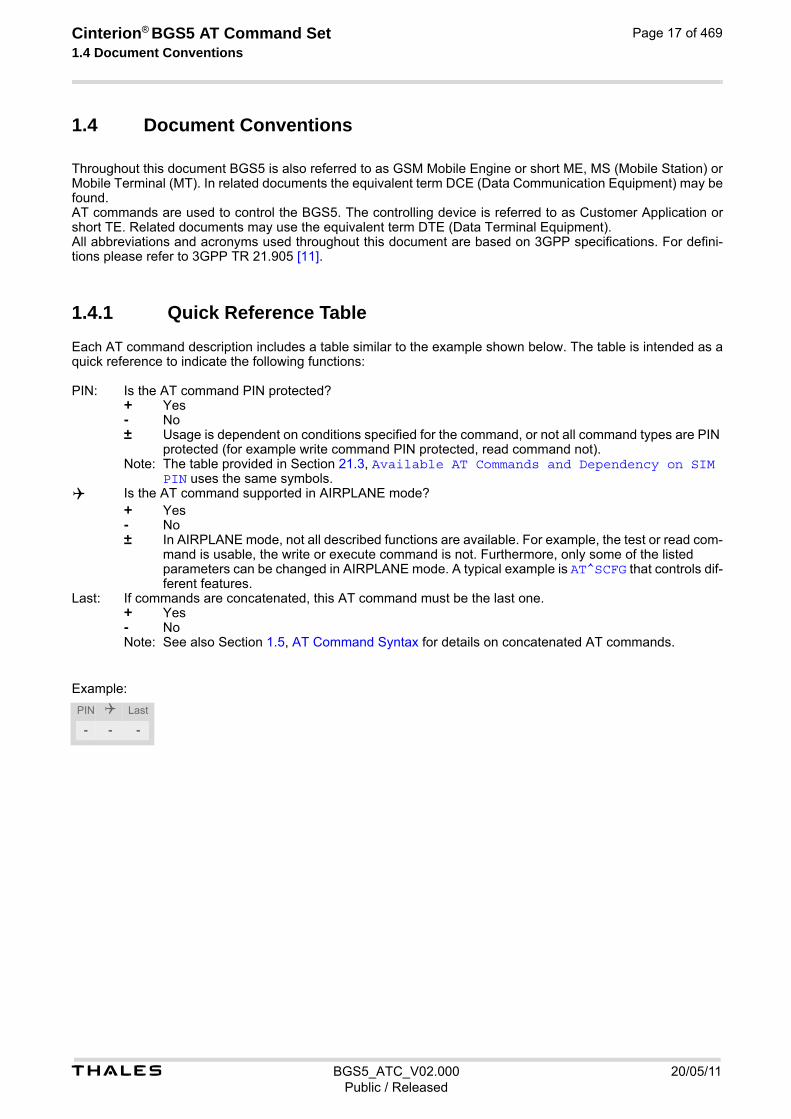
Each AT command description includes a table similar to the example shown below. The table is intended as a quick reference to indicate the following functions:
Example:
PIN: Is the AT command PIN protected? + Yes - No ± Usage is dependent on conditions specified for the command, or not all command types are PIN
protected (for example write command PIN protected, read command not). Note: The table provided in Section 21.3, Available AT Commands and Dependency on SIM
PIN uses the same symbols. Is the AT command supported in AIRPLANE mode? + Yes - No ± In AIRPLANE mode, not all described functions are available. For example, the test or read com-
mand is usable, the write or execute command is not. Furthermore, only some of the listed parameters can be changed in AIRPLANE mode. A typical example is AT^SCFG that controls dif-ferent features.
Last: If commands are concatenated, this AT command must be the last one. + Yes - No Note: See also Section 1.5, AT Command Syntax for details on concatenated AT commands.
PIN Last
- - -

t BGS5_ATC_V02.000 20/05/11Public / Released
Cinterion® BGS5 AT Command Set 1.4 Document Conventions
Page 18 of 469
1.4.2 Superscript notation for parameters and values
Table 1.1: Symbols used to mark the type of parameters
Table 1.2: Symbols used to indicate storage options or correlations with other commands
Table 1.3: Symbols used to mark different types of default values of parameters
Parameter type Meaning
<param>(num) Parameter value must be numeric type.
<param>(str) Parameter value must be string type.
<param>(text) Parameter value is a string according to selected character set. Not enclosed in double quotes
<param>(u) Unspecified, i.e. parameter value may be numeric or string type.
Parameter option Meaning
<param>(+CSCS) Parameter value has to be (is) coded according to current setting of <chset> (see AT+CSCS for details)
<param>(&W) Parameter value is stored to user profile in non-volatile memory after executing AT&W
<param>(&V) Parameter value is displayed by AT&V
<param>(NV) Parameter is stored in non-volatile memory.
Value option Meaning
[x] Default value set if parameter is omitted.
x(&F) Factory value restored by AT&F
x(P) Powerup value of a parameter not stored in non-volatile memory.
x(D) Delivery value of a parameter which may be overridden from non-volatile setting (refer to symbol (NV) and symbol (&W) above).

t BGS5_ATC_V02.000 20/05/11Public / Released
Cinterion® BGS5 AT Command Set 1.5 AT Command Syntax
Page 19 of 469
1.5 AT Command Syntax
The "AT" or "at" prefix must be set at the beginning of each command line. To terminate a command line enter <CR>. Commands are usually followed by a response that includes "<CR><LF><response><CR><LF>". Throughout this document, only the responses are presented, <CR><LF> are omitted intentionally.
Table 1.4: Types of AT commands and responses
1.5.1 Using Parameters
• Parameters are separated by commas. Please note that throughout this document spaces behind commas may be added for better readability.
• Optional parameters are enclosed in square brackets. If optional parameters are omitted and no default value is explicitly specified, the current settings are used until you change them.
• Optional parameters or subparameters can be omitted unless they are followed by other parameters. If you want to omit a parameter in the middle of a command string it must be replaced by a comma. See also exam-ple 1.
• A parameter value enclosed in square brackets represents the value that will be used if an optional parameter is omitted.
• When the parameter is a character string, e.g. <text> or <number>, the string must be enclosed in quotation marks, e.g. "Charlie Brown" or "+49030xxxx". Symbols in quotation marks will be recognized as strings.
• All spaces will be ignored when using strings without quotation marks.
• It is possible to omit the leading zeros of strings which represent numbers.
• If an optional parameter of a ITU-T V.250 command is omitted, its value is assumed to be 0.
Example 1: Omitting parameters in the middle of a string
Example 2: Using default parameter values for optional parameters
AT command type Syntax Function
Test command AT+CXXX=? The test response returns supported parameters and supported values. Values can be shown as a list of single values or a range, for example, (1,2,3) or (1-3).
Read command AT+CXXX? This command returns the currently set value of the parameter or parameters.
Write command AT+CXXX=<...> This command sets user-definable parameter values.
Exec(ution) command AT+CXXX The execution command reads non-variable parameters deter-mined by internal processes in the ME.
AT+CCUG? Query current setting+CCUG: 1,10,1OKAT+CCUG=,9 Set only the middle parameterOKAT+CCUG? Query new setting+CCUG: 1,9,1OK
AT+CREG= Setting default values for AT+CREG.OKAT+CREG? Query settings.+CREG: 0,0 AT+CREG default values are set.OK

t BGS5_ATC_V02.000 20/05/11Public / Released
Cinterion® BGS5 AT Command Set 1.5 AT Command Syntax
Page 20 of 469
1.5.2 Concatenating AT Commands
Concatenating AT commands on the same line is possible, though not recommended because of restrictions listed below (for more details see ITU-T V.250 [15]). When concatenating AT commands you need to enter the "AT" or "at" prefix only once at the beginning of a com-mand line. Basic commands (i.e., ITU-T V.250 commands) are concatenated without delimiter. Extended com-mands (i.e., commands starting with AT+ or AT^) use a semicolon as delimiter. Disadvantages and restrictions:
• There is no way to control the minimum time to wait between finishing an AT command and sending the next one. Please refer to Section 1.6, Communication between Customer Application and BGS5 for details about timing.
• The sequence of processing the AT commands may be different from the sequential order of command input.
• Many AT commands cannot be concatenated (see list below). Concatenating these commands might end up with an error result code, or leads to an unexpected order of responses.
1.5.3 Application Design Considerations
When designing your application keep in mind that parameters given in AT command responses, result codes and unsolicited result codes are only separated by commas with no spaces in between. Please take care that your application ignores any additional spaces that may, nevertheless, be inserted in some AT command responses, result codes and unsolicited result codes provided by BGS5.
AT command type Comment
3GPP TS 27.007 commands Cannot be concatenated with extended commands (prefix AT^S)
3GPP TS 27.005 commands (SMS) To be used standalone
Commands starting with AT& To be used standalone
AT+IPR To be used standalone

t BGS5_ATC_V02.000 20/05/11Public / Released
Cinterion® BGS5 AT Command Set 1.6 Communication between Customer Application and BGS5
Page 21 of 469
1.6 Communication between Customer Application and BGS5
After power-up or restart ensure that the ME is in ready state before trying to send any AT command or data. For detailed information on timing conditions, signal states and particularly the startup behavior of the BGS5's signal lines refer to the Hardware Interface Description [2]. Leaving hardware flow control unconsidered the Customer Application (TE) is coupled with the BGS5 (ME) via a receive and a transmit line. Since both lines are driven by independent devices collisions may (and will) happen. For example, if the TE issues an AT command and the BGS5 starts sending a URC. This will probably cause the TE to misinterpret the URC being part of the AT command's response. To avoid this conflict the following measures must be taken:
• If an AT command is finished (with "OK" or "ERROR") the TE shall always wait at least 100 ms before sending the next one. This applies to bit rates of 9600 bps or higher (see AT+IPR). At bit rates below 9600 bps the delay must be longer: 300 ms at 1200 bps, and 500 ms at 300 bps. The pause between two AT commands gives the BGS5 the opportunity to the transmission of pending URCs and get necessary service.
• The TE shall communicate with the BGS5 using activated echo (ATE1), i.e. the BGS5 echoes characters received from the TE. Hence, when the TE receives the echo of the first character "A" of the AT command just sent by itself it has control both over the receive and the transmit paths.
Using Backspace at command line:
• As the standard GSM alphabet does not provide a backspace functionality the BGS5 is designed to use the character "08" (hex 0x08) as backspace for command line input. This allows the user to easily erase the last character when writing an AT command. On the other hand, this solution requires entering the escape sequence \08 for writing the "ò" character in GSM character string parameters.
• If command echo is enabled (ATE1) Backspace may cause 08 - 32 - 08 (decimal) character sequence or no echo, depending on serial interface and speed of character input.
t BGS5_ATC_V02.000 20/05/11Public / Released
Cinterion® BGS5 AT Command Set 1.7 Supported character sets
Page 22 of 469
1.7 Supported character sets
BGS5 supports two character sets: GSM 7 bit, also referred to as GSM alphabet or SMS alphabet (3GPP TS 23.038 [33]) and UCS216 bit (ISO-10646 [12]). See AT+CSCS for information about selecting the character set. Character tables can be found below. Explanation of terms
• Escape Character There are two types of escape sequences which lead to an alternative interpretation on subsequent charac-ters by the ME:
- AT command interface Escape sequences starting with character value 0x5C are used for the ME's non-UCS2 input and output.
- GSM 7 bit default alphabet The escape sequence used within a text coded in the GSM 7 bit default alphabet is starting with character value 0x1B and needs to be correctly interpreted by the TE, both for character input and output. To the BGS5, an escape sequence appears like any other byte received or sent.
For SMS user data input after the prompt '>' in text mode (AT+CMGF)=1 and AT+CSCS="GSM" the character 0x1A is interpreted as 'CTRL-Z'. The character 0x1B (interpreted as 'ESC') as well as the escape character 0x5C (is interpreted as 'Ö'), therefore both escape mechanisms are not supported in this case.
• TE Character Set The character set currently used by the Customer Application is selected with AT+CSCS. It is recommended to select UCS2 setting.
• Data Coding Scheme (DCS) DCS is part of a short message and is saved on the SIM. When writing a short message to the SIM in text mode, the DCS stored with AT+CSMP is used and determines the coded character set.
• International Reference Alphabet (IRA) The International Reference Alphabet is equivalent to ASCII (American Standard Code for Information Inter-change) and ISO 646, i.e. it defines a 7-bit coded character set. The mapping can be obtained from the char-acter set tables below (UCS2 values 0x0000 to 0x007F).
When you enter characters that are not valid characters of the supported alphabets the behavior is undefined. If GSM alphabet is selected, all characters sent over the serial line (between TE and ME) must be in the range from 0 to 127 (7 bit range). Note: If the ME is configured for GSM alphabet, but the Customer Application (TE) uses ASCII, bear in mind that some characters have different code values, such as the following:
• "@" character with GSM alphabet value 0 is not displayable by an ASCII terminal program, e.g. Microsoft© Hyperterminal®.
• "@" character with GSM alphabet value 0 will terminate any C string! This is because value 0 is defined as C string end tag. Therefore, the GSM Null character will cause problems on application level when using 'C'-functions, e.g. "strlen()". Using an escape sequence as shown in the table below solves the problem. By the way, this may be the reason why even network providers sometimes replace '@' with "@=*" in their SIM appli-cation.
• Some other characters of the GSM alphabet may be misinterpreted by an ASCII terminal program. For exam-ple, GSM "ö" (as in "Börse") is assumed to be "|" in ASCII, thus resulting in "B|rse". This is because in both alphabets there are different characters assigned to value 7C (hexadecimal).
If the TE sends characters differently coded or undefined in ASCII or GSM (e.g. Ä, Ö, Ü) it is possible to use escape sequences. The ME's input parser translates the escape sequence to the corresponding GSM character value. Note: The ME also uses escape sequences for its non-UCS2 output: Quotation mark (") and the escape character itself (\, respectively Ö in GSM alphabet) are converted, as well as all characters with a value below 32 (hexadecimal 0x20). Hence, the input parser of the Customer Application needs to be able to translate escape sequences back to the corresponding character of the currently used alphabet. Unsupported characters are shown as a space (hexadecimal 0x20).

t BGS5_ATC_V02.000 20/05/11Public / Released
Cinterion® BGS5 AT Command Set 1.7 Supported character sets
Page 23 of 469
Table 1.5: Exemplary escape sequences generated by BGS5 for its non-UCS2 output
Usually terminal programs are not able to recognize escape sequences, and thus, handle them as normal char-acters. To prevent misinterpretation of control characters or special characters it is recommended to always use UCS2 alphabet and PDU mode.
Character Value
ASCII Character
GSM Character
UCS2 Character
Escape Sequence
Numeric Escape Sequence
0x5C \ Ö 00D6 \5C 0x5C 0x35 0x43
0x22 " " 0022 \22 0x5C 0x32 0x32
0x00 NULL @ n/a \00 0x5C 0x30 0x30

t BGS5_ATC_V02.000 20/05/11Public / Released
Cinterion® BGS5 AT Command Set 1.7 Supported character sets
Page 24 of 469
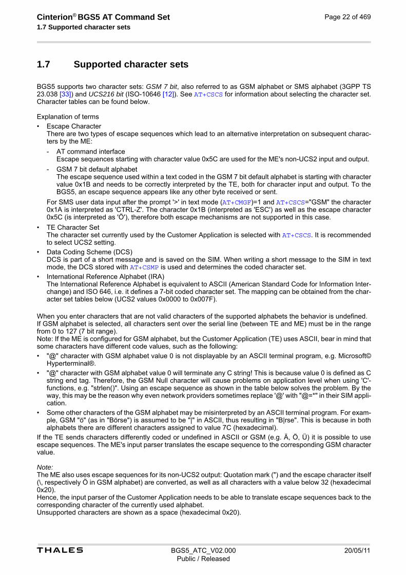
1.7.1 GSM alphabet tables and UCS2 character values
This section provides tables for the GSM default alphabet (3GPP TS 23.038 [33]) supported by the BGS5. Below any GSM character find the corresponding two byte character value of the UCS2 alphabet. For details refer to "ETSI GSM 03.38 mapping into Unicode" [13].
1) This code is an escape to the following extension of the 7 bit default alphabet table.
2) This code is not a printable character and therefore not defined for the UCS2 alphabet. It shall be treated as the accom-panying control character.
3) See Section 1.6 for further details on using backspace and "ò" character.
Figure 1.1: Main character table of GSM 7 bit default alphabet

t BGS5_ATC_V02.000 20/05/11Public / Released
Cinterion® BGS5 AT Command Set 1.7 Supported character sets
Page 25 of 469
1) This code value is reserved for the extension to another extension table. On receipt of this code, a receiving entity shall display a space until another extension table is defined.
2) This code represents the EURO currency symbol. The code value is the one used for the character 'e'. Therefore a receiv-ing entity which is incapable of displaying the EURO currency symbol will display the character 'e' instead.
3) This code is defined as a Page Break character and may be used for example in compressed CBS messages. Any mobile which does not understand the 7 bit default alphabet table extension mechanism will treat this character as Line Feed.
Figure 1.2: Extension character table of GSM 7 bit default alphabet

t BGS5_ATC_V02.000 20/05/11Public / Released
Cinterion® BGS5 AT Command Set 1.7 Supported character sets
Page 26 of 469
If the Customer Application receives a code where a symbol is not represented in Figure 1.2, Extension character table of GSM 7 bit default alphabet it shall display the character shown in the main GSM 7 bit default alphabet table (see Figure 1.1, Main character table of GSM 7 bit default alphabet).
1.7.2 UCS2 and GSM character coding and conversion
This section provides basic information on how to handle input and output character conversion, e.g. for SMS text mode, if the character representation of ME and Customer Application differ, i.e. if the Data Coding Scheme and the TE character set use different mappings.
1.7.2.1 Output of SIM data (ME to TE)
Note: The ratio of SIM bytes to output bytes is given in parentheses. Case 1 Every GSM character is sent to the TE as it is (8-bit value with highest bit set to zero). Example: 47'H, 53'H, 4D'H → 47'H, 53'H, 4D'H, displayed as "GSM" Case 2 Every data byte is sent to the TE as 2 IRA characters each representing a halfbyte. Example: B8'H (184 decimal) → 42'H, 38'H, displayed as "B8" Case 3 Every 16-bit UCS2 value is sent to the TE as 4 IRA characters. Example: C4xA7'H (50343 decimal) → 43'H, 34'H, 41'H, 37'H, displayed as "C4A7" Problem: An odd number of bytes leads to an error because there are always two bytes needed for each UCS2 character Case 4 Every GSM character is sent to the TE as 4 IRA characters to show UCS2 in text mode. Example: 41'H ("A") → 30'H, 30'H, 34'H, 31'H, displayed as "0041" Case 5 Every data byte is sent to the TE as IRA representation of UCS2 (similar to case 4). Example: B2'H → 30'H, 30'H, 42'H, 32'H, displayed as "00B2" Case 6 Every 16-bit value is sent to the TE as IRA representation of it. It is assumed that number of bytes is even. Example: C3x46'H → 43'H, 33'H, 34'H, 36'H, displayed as "C346"
Used character set DCS = 7 bit GSM
DCS = 8 bit Data
DCS = 16 bit UCS2
GSM Case 1 GSM (1:1)
Case 2 8 bit to IRA (1:2)
Case 3 UCS2 to IRA (2:4)
UCS2 Case 4 GSM to IRA (1:4)
Case 5 8 bit to IRA (1:4)
Case 6 UCS2 to IRA (2:4)

t BGS5_ATC_V02.000 20/05/11Public / Released
Cinterion® BGS5 AT Command Set 1.7 Supported character sets
Page 27 of 469
1.7.2.2 Input of SIM data (TE to ME)
Note: The ratio between the number of input characters and bytes stored on the SIM is given in parentheses. Case 1 Every character is sent from TE to ME as GSM character (or ASCII with standard terminal emulation, e.g. Hyper-terminal®). Character value must be in range from 0 to 127 because of 7-bit GSM alphabet. To reach maximum SMS text length of 160 characters in 140 bytes space characters will be compressed on SIM. This must be set using the parameter <dcs> of AT+CSMP (add 64). Example: "ABCDEFGH" typed is sent and stored uncompressed as → 4142434445464748'H (stored com-pressed as 41E19058341E91'H) Case 2 Every data byte is sent as 2 IRA characters. Maximum text length is 280 IRA characters which will be converted into 140 bytes SMS binary user data Example: "C8" typed is sent as 43'H, 38'H → stored as C8'H Case 3 Every 16-bit value is sent as 4 IRA characters. Maximum text length is 280 IRA characters which will be converted into 70 UCS2 characters (16-bit each) Number of IRA characters must be a multiple of four because always 4 half bytes are needed for a 16-bit value Example: "D2C8" typed is sent as 44'H, 32'H, 43'H, 38'H → stored as D2C8'H Case 4 Every GSM character is sent as 4 IRA characters representing one UCS2 character. Example: To store text "ABC" using UCS2 character set you have to type "004100420043". This is sent as 30'H,30'H,34'H,31'H, 30'H,30'H,34'H,32'H, 30'H,30'H,34'H,33'H → detected as IRA representa-tion of 3 UCS2 characters, converted to GSM character set and stored as 41'H, 42'H, 43'H. Maximum input is 640 IRA characters representing 160 UCS2 characters when compression is active. These are converted to 160 GSM 7-bit characters. Without compression only 140 GSM characters can be stored which are put in as 560 IRA characters. Values of UCS2 characters must be smaller than 80'H (128 decimal) to be valid GSM characters. Number of IRA characters must be a multiple of four. Problems: • "41" → Error, there are four IRA characters (two bytes) needed • "0000" → Error, not an UCS2 character • "4142" → Error, value of UCS2 character > 7F'H • "008B" → Error, value of UCS2 character > 7F'H This affects the maximum input length of a string) Case 5 Every UCS2 character is sent as 4 IRA characters and is converted into two 8-bit values. This means that the first two characters have to be '00'. Example: UCS2 character 009F'H typed as "009F" is sent as 30'H,30'H,39'H,46'H → converted into 8-bit value 9F'H. Maximum number of UCS2 characters is 140 which are represented by 560 IRA characters. Number of IRA char-acters must be a multiple of four. Case 6 Every UCS2 character is sent as 4 IRA characters each and is converted into a 16-bit value again. Example: UCS2 character 9F3A'H typed as "9F3A" is sent as 39'H,46'H,33'H,41'H → converted into 9F3A'H. Maximum number of UCS2 characters is 70 which are represented by 280 IRA characters. Number of IRA char-acters must be a multiple of four. Invalid UCS2 values must be prevented.
Used character set DCS = 7 bit GSM
DCS = 8 bit Data
DCS = 16 bit UCS2
GSM Case 1 GSM (1:1)
Case 2 IRA to 8 bit (2:1)
Case 3 IRA to 16 bit (4:2)
UCS2 Case 4 UCS2 to GSM (4:1)
Case 5 UCS2 to 8 bit (4:1)
Case 6 UCS2 to 16 bit (4:2)

t BGS5_ATC_V02.000 20/05/11Public / Released
Cinterion® BGS5 AT Command Set 1.8 Unsolicited Result Code Presentation
Page 28 of 469
1.8 Unsolicited Result Code Presentation
URC stands for Unsolicited Result Code and is a report message issued by the ME without being requested by the TE, i.e. a URC is issued automatically when a certain event occurs. Hence, a URC is not issued as part of the response related to an executed AT command. Typical events leading to URCs are incoming calls ("RING"), waiting calls, received short messages, changes in temperature, network registration etc. For most of these messages, the ME needs to be configured whether or not to send a URC. Descriptions of these URCs are provided with the associated AT command. URCs which are not user definable are described in Sec-tion 1.8.1, Common URCs. A summary of all URCs can be found in Section 21.7, Summary of Unsolicited Result Codes (URC). Important: If the interface used for URC output is reserved by an active data connection or a long running AT command, URCs are buffered internally and will be issued after the interface becomes idle again. A pending URC will be signaled on the URC output interface via RING line. This allows to systematically suspend any longer data connection (refer +++ and ATO) to check for pending URCs after being signaled! For detailed information regarding configuration of URC signaling refer to AT^SCFG, "URC/Ringline", <urcRin-glineCfg>.
Parameter Description
200 URC will be send 40 seconds after powerup when the JRC midlet was not tried to start (no autostart, no midlet at all, whatever). Used to see in logs, that midlet is not running, as example.
201 The JRC midlet was started, but did not succeed to full init itself within a (JRC midlet defined) timeout. 5 seconds after this URC, the ME will restart.
202 The midlet was tried to start 5x, but was restarted (with ^SYSINFO: 201). Now, the JRC midlet start was cancelled. No JRC midlet is running. A shutdown timer of 10 minutes is started. After this timer, the ME will be switched off.
1.8.1 Common URCs
This section describes all URCs not associated to a certain AT command. They cannot be defined by the user and appear automatically when the conditions described below occur. Notes for "^SBC" URCs reporting undervoltage/overvoltage conditions: Please refer to [2] for specifications regarding the minimum and maximum operating voltage limits. If the supply voltage exceeds the defined thresholds the ME switches off automatically. The automatic shutdown procedure is equivalent to the power-down initiated with the AT^SMSO command.
URC 1
^SYSLOADING
Indicates that the ME is in the process of starting up. Do not enter AT commands until the "^SYSSTART" URC has shown up.
URC 2
^SYSSTART
Indicates that the ME has been restarted to Normal mode or Airplane mode and is ready to operate. For Normal and Airplane mode see AT+CFUN. Note: Autobaud mode (see AT+IPR) requires an "AT" or "at" string be given after restarting the ME. This enables the ME to detect the bit rate set in the TE. After detecting the bit rate the ME will send the "^SYS-START" URC.
<info>(num)
t BGS5_ATC_V02.000 20/05/11Public / Released
Cinterion® BGS5 AT Command Set 1.8 Unsolicited Result Code Presentation
Page 29 of 469
URC 3
+PBREADY
After SIM PIN authentication has completed this URC indicates that the ME has completed reading data from the SIM and that phonebook and SMS functions are ready for read and write operation. Any attempt to use phonebook or SIM PIN dependent SMS AT commands before the ME has finished reading SIM data will be denied with error codes, such as "+CME ERROR: SIM busy" or "+CMS ERROR: SIM busy".
URC 4
^SYSINFO: <info>
System information URC.
URC 5
^SBC: Undervoltage Warning
Supply voltage is close to the defined undervoltage threshold.
URC 6
^SBC: Undervoltage Shutdown
Undervoltage threshold exceeded. ME automatically switches off.
URC 7
^SBC: Overvoltage Warning
Supply voltage is close to defined overvoltage threshold.
URC 8
^SBC: Overvoltage Shutdown
Overvoltage threshold exceeded. ME automatically switches off.
t BGS5_ATC_V02.000 20/05/11Public / Released
Cinterion® BGS5 AT Command Set 1.9 Errors and Messages
Page 30 of 469
1.9 Errors and Messages
The command result codes "+CME ERROR: <err>" and "+CMS ERROR: <err>" indicate errors related to mobile equipment or network functionality. The format of <err> can be either numeric or verbose and is selectable via AT+CMEE. A result error code terminates the execution of the command and prevents the execution of all remaining com-mands that may follow on the same command line. If so, neither "ERROR" nor "OK" result codes are returned for these commands. A 30 seconds timeout will deliver "ERROR" when the input of a command is not complete. Using the wrong command syntax may result in errors: For example, using the execute command syntax although the command has no execute format, causes "ERROR" to be returned. Likewise, using the write com-mand syntax although the command has no write format causes "+CME ERROR: <err>" to be returned. See also:
• Section 2.10.1, CME/CMS Error Code Overview
• Section 2.5.1, Verbose and numeric result codes
• Section 3.1, AT+CEER

Cinterion® BGS5 AT Command Set 2. Configuration Commands
t BGS5_ATC_V02.000 20/05/11Public / Released
Page 31 of 469
2. Configuration Commands
The AT Commands described in this chapter allow the external application to determine the BGS5's behaviour under various conditions.
2.1 AT&F Reset AT Command Settings to Factory Default Values
AT&F resets AT command settings to their factory default values. For a list of affected parameters refer to Section 21.6, Factory Default Settings Restorable with AT&F.
Syntax
Parameter Description
[0] Reset parameters in Section 21.6, Factory Default Settings Restor-able with AT&F to their factory default values.
Exec Command
AT&F[<value>]Response(s)
OK
PIN Last Reference(s)
- + - V.250
<value>(num)
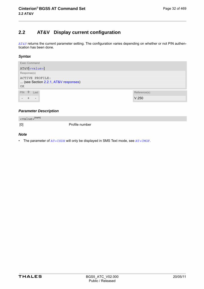
t BGS5_ATC_V02.000 20/05/11Public / Released
Cinterion® BGS5 AT Command Set 2.2 AT&V
Page 32 of 469
2.2 AT&V Display current configuration
AT&V returns the current parameter setting. The configuration varies depending on whether or not PIN authen-tication has been done.
Syntax
Parameter Description
[0] Profile number Note• The parameter of AT+CSDH will only be displayed in SMS Text mode, see AT+CMGF.
Exec Command
AT&V[<value>]Response(s)
ACTIVE PROFILE:... (see Section 2.2.1, AT&V responses)OK
PIN Last Reference(s)
- + - V.250
<value>(num)

t BGS5_ATC_V02.000 20/05/11Public / Released
Cinterion® BGS5 AT Command Set 2.2 AT&V
Page 33 of 469
2.2.1 AT&V responses
The following table shows different kinds of responses depending on whether or not the PIN is entered.
PIN authentication done No PIN authentication
ACTIVE PROFILE: E1 Q0 V1 X4 &C1 &D2 &S0 \Q3 S0:000 S3:013 S4:010 S5:008 S6:000 S7:060 S8:000 S10:002 +CBST: 7,0,1 +CRLP: 61,61,78,6 +CR: 0 +CRC: 0 +CMGF: 1 +CSDH: 0 +CNMI: 0,0,0,0,1 +ICF: 3 +IPR: 115200 +CMEE: 2 +CSMS: 0,1,1,1 +CREG: 0,1 +CLIP: 0,2 +COPS: 0,0,"operator",0 +CGSMS: 1 OK
ACTIVE PROFILE: E1 Q0 V1 X4 &C1 &D2 &S0 \Q3 S0:000 S3:013 S4:010 S5:008 S6:000 S7:060 S8:000 S10:002 +CBST: 7,0,1 +CRLP: 61,61,78,6 +CR: 0 +ICF: 3 +IPR: 115200 OK
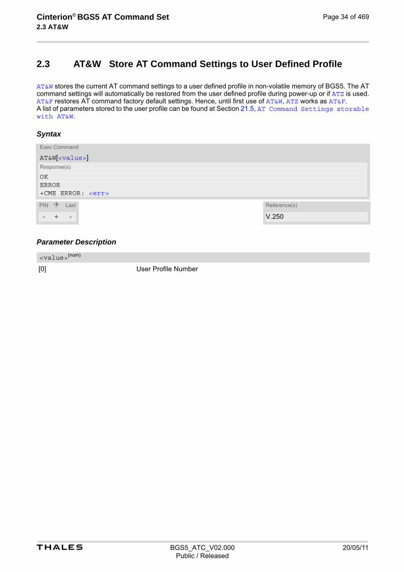
t BGS5_ATC_V02.000 20/05/11Public / Released
Cinterion® BGS5 AT Command Set 2.3 AT&W
Page 34 of 469
2.3 AT&W Store AT Command Settings to User Defined Profile
AT&W stores the current AT command settings to a user defined profile in non-volatile memory of BGS5. The AT command settings will automatically be restored from the user defined profile during power-up or if ATZ is used. AT&F restores AT command factory default settings. Hence, until first use of AT&W, ATZ works as AT&F. A list of parameters stored to the user profile can be found at Section 21.5, AT Command Settings storable with AT&W.
Syntax
Parameter Description
[0] User Profile Number
Exec Command
AT&W[<value>]Response(s)
OKERROR+CME ERROR: <err>
PIN Last Reference(s)
- + - V.250
<value>(num)

t BGS5_ATC_V02.000 20/05/11Public / Released
Cinterion® BGS5 AT Command Set 2.4 ATQ
Page 35 of 469
2.4 ATQ Result Code Presentation Mode
ATQ controls if the BGS5 transmits any result code to the TE. Other information text transmitted as response is not affected.
Syntax
Parameter Description
Result Code Presentation Mode. It is not recommended to change this value.
[0](&F)(D) ME transmits result code.
1 Result codes are suppressed and not transmitted.
Exec Command
ATQ[<n>]Response(s)
If <n>=0:OKIf <n>=1:(none)
PIN Last Reference(s)
- + - V.250
<n>(num)(&V)(&W)

t BGS5_ATC_V02.000 20/05/11Public / Released
Cinterion® BGS5 AT Command Set 2.5 ATV
Page 36 of 469
2.5 ATV Result code format mode
This command determines the contents of header and trailer transmitted with AT command result codes and information responses. Possible responses are described in Section 2.5.1, Verbose and numeric result codes.
Syntax
Parameter Description
[0] Information response: <text><CR><LF> Short result code format: <numeric code><CR>
1(&F)(D) Information response: <CR><LF><text><CR><LF> Long result code format: <CR><LF><verbose code><CR><LF>
2.5.1 Verbose and numeric result codes
Exec Command
ATV[<value>]Response(s)
OKERROR
PIN Last Reference(s)
- + - ITU-T V.250 [15]
<value>(num)(&V)(&W)
Verbose format Numeric format Meaning
OK 0 command executed, no errors
CONNECT 1 link established
RING 2 ring detected
NO CARRIER 3 link not established or disconnected
ERROR 4 invalid command or command line too long
NO DIALTONE 6 no dial tone, dialling impossible, wrong mode
BUSY 7 remote station busy
NO ANSWER 8 no answer
CONNECT 2400/RLP 10 link with 2400 bps
CONNECT 4800/RLP 11 link with 4800 bps
CONNECT 9600/RLP 12 link with 9600 bps
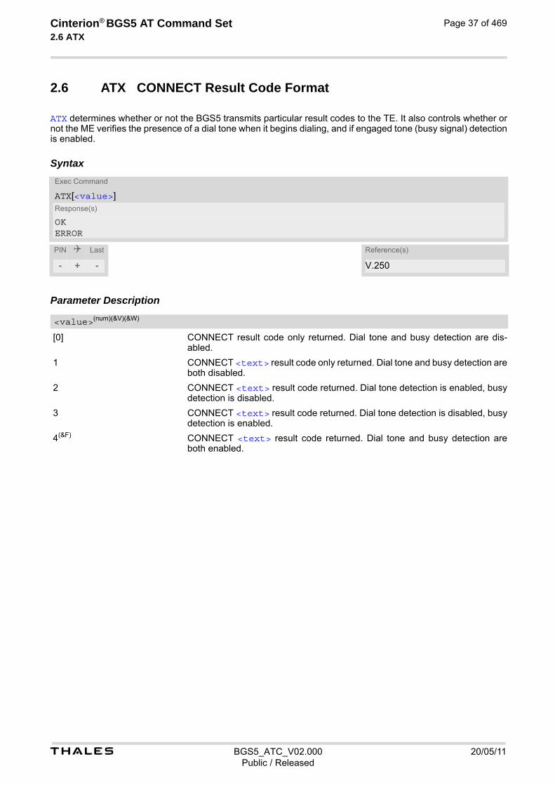
t BGS5_ATC_V02.000 20/05/11Public / Released
Cinterion® BGS5 AT Command Set 2.6 ATX
Page 37 of 469
2.6 ATX CONNECT Result Code Format
ATX determines whether or not the BGS5 transmits particular result codes to the TE. It also controls whether or not the ME verifies the presence of a dial tone when it begins dialing, and if engaged tone (busy signal) detection is enabled.
Syntax
Parameter Description
[0] CONNECT result code only returned. Dial tone and busy detection are dis-abled.
1 CONNECT <text> result code only returned. Dial tone and busy detection are both disabled.
2 CONNECT <text> result code returned. Dial tone detection is enabled, busy detection is disabled.
3 CONNECT <text> result code returned. Dial tone detection is disabled, busy detection is enabled.
4(&F) CONNECT <text> result code returned. Dial tone and busy detection are both enabled.
Exec Command
ATX[<value>]Response(s)
OKERROR
PIN Last Reference(s)
- + - V.250
<value>(num)(&V)(&W)

t BGS5_ATC_V02.000 20/05/11Public / Released
Cinterion® BGS5 AT Command Set 2.7 ATZ
Page 38 of 469
2.7 ATZ Restore AT Command Settings from User Defined Profile
ATZ is supported for compatibility with other products. The command command restores the user defined profile on user request.
Syntax
Parameter Description
1...65535 The stored profile will be restored with any valid number.
Exec Command
ATZ[<value>]Response(s)
OK
PIN Last Reference(s)
- + - V.250
<value>(num)
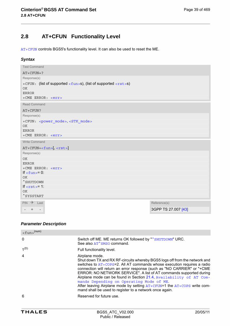
t BGS5_ATC_V02.000 20/05/11Public / Released
Cinterion® BGS5 AT Command Set 2.8 AT+CFUN
Page 39 of 469
2.8 AT+CFUN Functionality Level
AT+CFUN controls BGS5's functionality level. It can also be used to reset the ME.
Syntax
Parameter Description
0 Switch off ME. ME returns OK followed by "^SHUTDOWN" URC. See also AT^SMSO command.
1(D) Full functionality level.
4 Airplane mode. Shut down TX and RX RF-circuits whereby BGS5 logs off from the network and switches to AT+COPS=2. All AT commands whose execution requires a radio connection will return an error response (such as "NO CARRIER" or "+CME ERROR: NO NETWORK SERVICE". A list of AT commands supported during Airplane mode can be found in Section 21.4, Availability of AT Com-mands Depending on Operating Mode of ME. After leaving Airplane mode by setting AT+CFUN=1 the AT+COPS write com-mand shall be used to register to a network once again.
6 Reserved for future use.
Test Command
AT+CFUN=?Response(s)
+CFUN: (list of supported <fun>s), (list of supported <rst>s)OKERROR+CME ERROR: <err>
Read Command
AT+CFUN?Response(s)
+CFUN: <power_mode>, <STK_mode>OKERROR+CME ERROR: <err>
Write Command
AT+CFUN=<fun>[, <rst>]Response(s)
OKERROR+CME ERROR: <err>If <fun>= 0:OK^SHUTDOWNIf <rst>= 1:OK^SYSSTART
PIN Last Reference(s)
- + - 3GPP TS 27.007 [43]
<fun>(num)
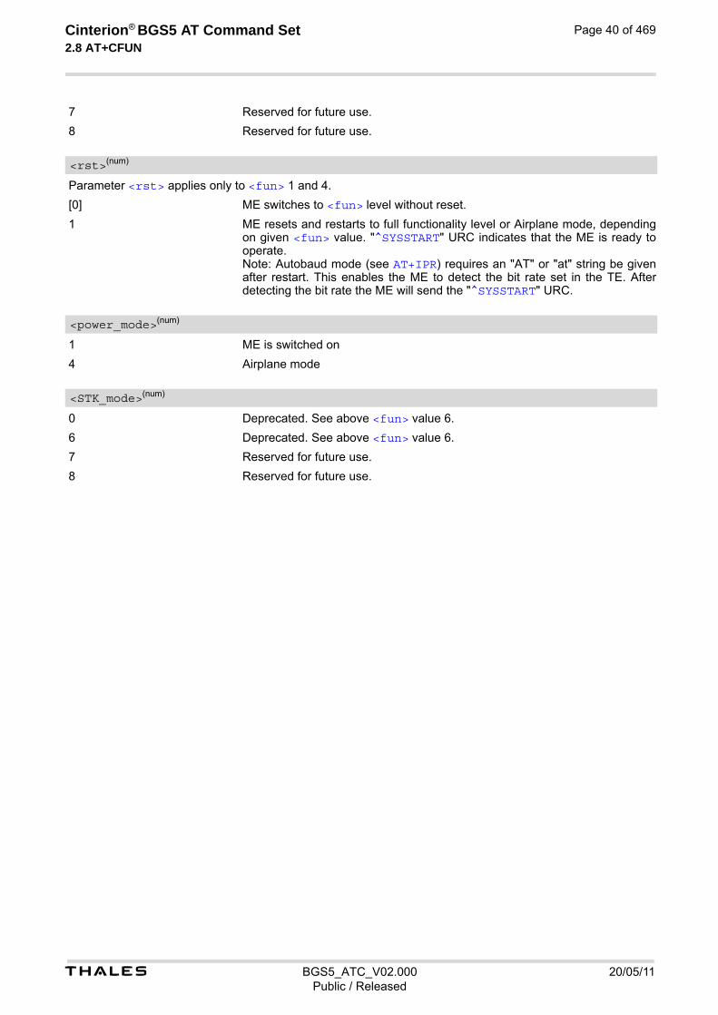
t BGS5_ATC_V02.000 20/05/11Public / Released
Cinterion® BGS5 AT Command Set 2.8 AT+CFUN
Page 40 of 469
7 Reserved for future use.
8 Reserved for future use.
Parameter <rst> applies only to <fun> 1 and 4.
[0] ME switches to <fun> level without reset.
1 ME resets and restarts to full functionality level or Airplane mode, depending on given <fun> value. "^SYSSTART" URC indicates that the ME is ready to operate. Note: Autobaud mode (see AT+IPR) requires an "AT" or "at" string be given after restart. This enables the ME to detect the bit rate set in the TE. After detecting the bit rate the ME will send the "^SYSSTART" URC.
1 ME is switched on
4 Airplane mode
0 Deprecated. See above <fun> value 6.
6 Deprecated. See above <fun> value 6.
7 Reserved for future use.
8 Reserved for future use.
<rst>(num)
<power_mode>(num)
<STK_mode>(num)
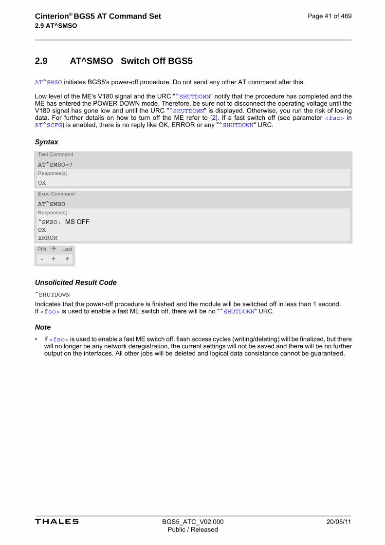
t BGS5_ATC_V02.000 20/05/11Public / Released
Cinterion® BGS5 AT Command Set 2.9 AT^SMSO
Page 41 of 469
2.9 AT^SMSO Switch Off BGS5
AT^SMSO initiates BGS5's power-off procedure. Do not send any other AT command after this. Low level of the ME's V180 signal and the URC "^SHUTDOWN" notify that the procedure has completed and the ME has entered the POWER DOWN mode. Therefore, be sure not to disconnect the operating voltage until the V180 signal has gone low and until the URC "^SHUTDOWN" is displayed. Otherwise, you run the risk of losing data. For further details on how to turn off the ME refer to [2]. If a fast switch off (see parameter <fso> in AT^SCFG) is enabled, there is no reply like OK, ERROR or any "^SHUTDOWN" URC.
Syntax
Unsolicited Result Code^SHUTDOWN
Indicates that the power-off procedure is finished and the module will be switched off in less than 1 second. If <fso> is used to enable a fast ME switch off, there will be no "^SHUTDOWN" URC. Note• If <fso> is used to enable a fast ME switch off, flash access cycles (writing/deleting) will be finalized, but there
will no longer be any network deregistration, the current settings will not be saved and there will be no further output on the interfaces. All other jobs will be deleted and logical data consistance cannot be guaranteed.
Test Command
AT^SMSO=?Response(s)
OK
Exec Command
AT^SMSOResponse(s)
^SMSO: MS OFFOKERROR
PIN Last
- + +
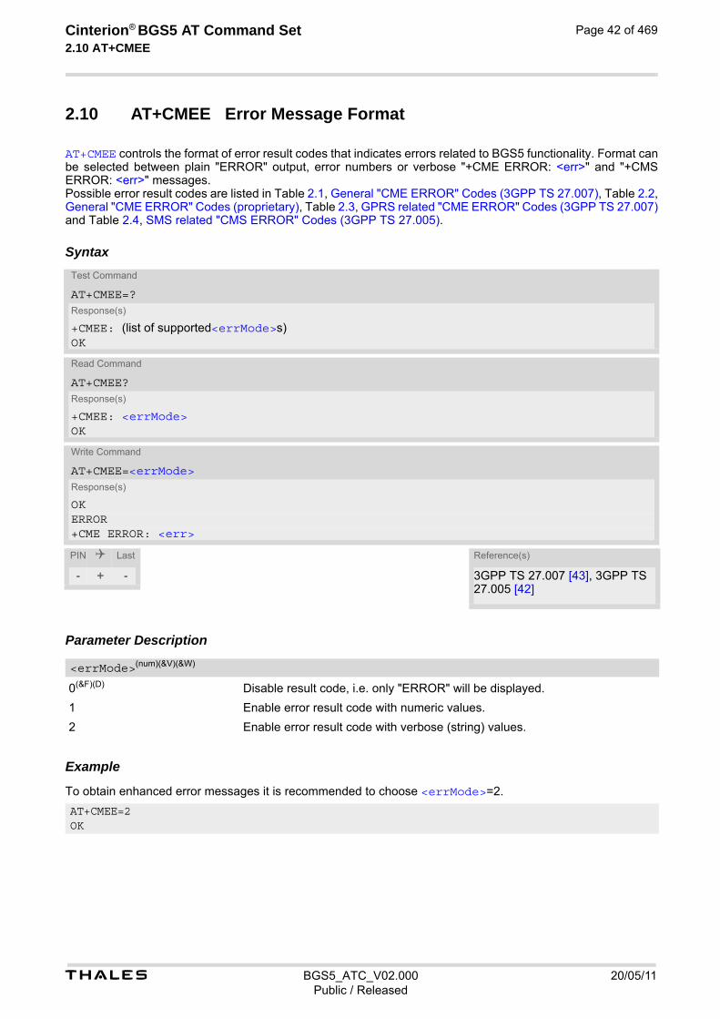
t BGS5_ATC_V02.000 20/05/11Public / Released
Cinterion® BGS5 AT Command Set 2.10 AT+CMEE
Page 42 of 469
2.10 AT+CMEE Error Message Format
AT+CMEE controls the format of error result codes that indicates errors related to BGS5 functionality. Format can be selected between plain "ERROR" output, error numbers or verbose "+CME ERROR: <err>" and "+CMS ERROR: <err>" messages. Possible error result codes are listed in Table 2.1, General "CME ERROR" Codes (3GPP TS 27.007), Table 2.2, General "CME ERROR" Codes (proprietary), Table 2.3, GPRS related "CME ERROR" Codes (3GPP TS 27.007) and Table 2.4, SMS related "CMS ERROR" Codes (3GPP TS 27.005).
Syntax
Parameter Description
0(&F)(D) Disable result code, i.e. only "ERROR" will be displayed.
1 Enable error result code with numeric values.
2 Enable error result code with verbose (string) values.
Example To obtain enhanced error messages it is recommended to choose <errMode>=2.
Test Command
AT+CMEE=?Response(s)
+CMEE: (list of supported<errMode>s)OK
Read Command
AT+CMEE?Response(s)
+CMEE: <errMode>OK
Write Command
AT+CMEE=<errMode>Response(s)
OK ERROR +CME ERROR: <err>
PIN Last Reference(s)
- + - 3GPP TS 27.007 [43], 3GPP TS 27.005 [42]
<errMode>(num)(&V)(&W)
AT+CMEE=2OK

t BGS5_ATC_V02.000 20/05/11Public / Released
Cinterion® BGS5 AT Command Set 2.10 AT+CMEE
Page 43 of 469
2.10.1 CME/CMS Error Code Overview
Table 2.1: General "CME ERROR" Codes (3GPP TS 27.007)
+CME <err> Code Text (if AT+CMEE=2)
0 phone failure
1 no connection to phone
2 phone adapter link reserved
3 operation not allowed
4 operation not supported
5 PH-SIM PIN required
6 PH-FSIM PIN required
7 PH-FSIM PUK required
10 SIM not inserted
11 SIM PIN required
12 SIM PUK required
13 SIM failure
14 SIM busy
15 SIM wrong
16 incorrect password
17 SIM PIN2 required
18 SIM PUK2 required
20 memory full
21 invalid index
22 not found
23 memory failure
24 text string too long
25 invalid characters in text string
26 dial string too long
27 invalid characters in dial string
30 no network service
31 network timeout
32 network not allowed - emergency calls only
40 network personalization PIN required
41 network personalization PUK required
42 network subset personalization PIN required
43 network subset personalization PUK required
44 service provider personalization PIN required
45 service provider personalization PUK required
46 corporate personalization PIN required
47 corporate personalization PUK required
48 hidden key required (NOTE: This key is required when accessing hidden phonebook entries.)
49 EAP method not supported

t BGS5_ATC_V02.000 20/05/11Public / Released
Cinterion® BGS5 AT Command Set 2.10 AT+CMEE
Page 44 of 469
Table 2.2: General "CME ERROR" Codes (proprietary)
Table 2.3: GPRS related "CME ERROR" Codes (3GPP TS 27.007)
50 Incorrect parameters
100 Unknown
256 operation temporary not allowed
257 call barred
261 SS not executed
500 CTS Handover on Progress
501 Cellular Protocol Stack Out of service state
502 CTS Unspecified Error
+CME <err> Code Text (if AT+CMEE=2)
615 network failure
616 network is down
639 service type not yet available
640 operation of service temporary not allowed
650 resolve host name failure
764 missing input value
765 invalid input value
767 operation failed
+CME <err> Code Text (if AT+CMEE=2)
103 illegal MS
106 illegal ME
107 GPRS services not allowed
111 PLMN not allowed
112 location area not allowed
113 roaming not allowed in this location area
132 service option not supported
133 requested service option not subscribed
134 service option temporary out of order
148 unspecified GPRS error
149 PDP authentication failure
150 invalid mobile class
151 Unassigned (unallocated) number
152 No route to destination
153 Channel unacceptable
154 Operator determined barring
155 Normal call clearing
156 User busy
157 No user responding
158 User alerting, no answer
+CME <err> Code Text (if AT+CMEE=2)

t BGS5_ATC_V02.000 20/05/11Public / Released
Cinterion® BGS5 AT Command Set 2.10 AT+CMEE
Page 45 of 469
159 Call rejected
160 Number changed
161 Non selected user clearing
162 Destination out of order
163 Invalid number format (incomplete number)
164 Facility rejected
165 Response to STATUS ENQUIRY
166 Normal, unspecified
167 No circuit/channel available
168 Network out of order
169 Temporary failure
170 Switching equipment congestion
171 Access information discarded
172 requested circuit/channel not available
173 Resources unavailable, unspecified
174 Quality of service unavailable
175 Requested facility not subscribed
176 Incoming calls barred within the CUG
177 Bearer capability not authorized
178 Bearer capability not presently available
179 Service or option not available, unspecified
180 Bearer service not implemented
181 ACM equal to or greater than ACMmax
182 Requested facility not implemented
183 Only restr. digital information bearer capability
184 Service or option not implemented, unspecified
185 Invalid transaction identifier value
186 User not member of CUG
187 Incompatible destination
188 Invalid transit network selection
189 Semantically incorrect message
190 Invalid mandatory information
191 Message type non-existent or not implemented
192 Message type not compatible with protocol state
193 Information element non-existent or not implemented
194 Conditional IE error
195 Message not compatible with protocol state
196 Recovery on timer expiry
197 Protocol error, unspecified
198 Interworking, unspecified
199 Number not allowed
+CME <err> Code Text (if AT+CMEE=2)

t BGS5_ATC_V02.000 20/05/11Public / Released
Cinterion® BGS5 AT Command Set 2.10 AT+CMEE
Page 46 of 469
Table 2.4: SMS related "CMS ERROR" Codes (3GPP TS 27.005)
200 CCBS possible
596 GPRS - invalid CID value
+CMS <err> Code Text (if AT+CMEE=2)
1 unassigned (unallocated) number
8 operator determined barring
10 call barred
13 SMS timer expired
14 SMS forwarding availability failed
17 Network failure
21 Short message transfer rejected
22 Memory capacity exceeded
27 Destination out of order (service)
28 unidentified subscriber
29 facility rejected
30 unknown subscriber
38 Network out of order (service)
41 temporary failure
42 congestion
47 Resource unavailable, unspecified
50 requested facility not subscribed
69 requested facility not implemented
81 invalid short message transfer reference value
95 Semantically invalid message, unspecified
96 invalid mandatory information
97 message type non-existent or not implemented
98 message not compatible with short message protocol state
99 information element non-existent or not implemented
111 protocol error, unspecified
127 interworking, unspecified
128 telematic interworking not supported
129 short message type 0 not supported
130 cannot replace short message
143 unspecified TP-PID error
144 data coding scheme (alphabet) not supported
145 message class not supported
159 unspecified TP-DCS error
160 command cannot be actioned
161 command unsupported
175 unspecified TP-command error
176 TPDU not supported
+CME <err> Code Text (if AT+CMEE=2)

t BGS5_ATC_V02.000 20/05/11Public / Released
Cinterion® BGS5 AT Command Set 2.10 AT+CMEE
Page 47 of 469
192 SC busy
193 no SC subscription
194 SC system failure
195 Invalid Short Message Entity(SME) address (MO)
196 Destination SME barred (MO)
197 SM rejected duplicated SM (MO)
198 TP-VPF (validity period format) not supported (MO)
199 TP-VP (validity period) not supported (MO)
208 (U)SIM SMS storage full (MT)
209 no SMS storage capability in (U)SIM (MT)
210 Error in MS (MT)
211 Memory capacity exceeded (MT)
212 (U)SIM Application Toolkit busy
213 (U)SIM data download error
255 unspecified error cause
287 Network failure unspecified
290 Network no resource
300 ME failure
301 SMS service of ME reserved
302 operation not allowed
303 operation not supported
304 invalid PDU mode parameter
305 invalid text mode parameter
310 SIM not inserted
311 SIM PIN necessary
312 PH-SIM PIN necessary
313 SIM failure
314 SIM busy
315 SIM wrong
320 Memory failure
321 Invalid memory index
322 Memory full
330 SMSC address unknown
331 No network service
332 Network timeout
340 No CNMA acknowledgement expected
500 Unknown error
512 Relay path Acknowledgement
513 SMS timer expired
514 SMS forwarding availability failed
515 SMS forwarding availability aborted
516 Invalid TP-MESSAGE-Type Indicator
+CMS <err> Code Text (if AT+CMEE=2)

t BGS5_ATC_V02.000 20/05/11Public / Released
Cinterion® BGS5 AT Command Set 2.10 AT+CMEE
Page 48 of 469
517 No TP-Status Report in Phase 1
518 No TP-Reject-Duplicate in Phase 1
519 No TP-Reply-Path in Phase 1
520 No TP-User-Data-Header in Phase 1
521 Missing TP-Validity-Period
522 Invalid TP-Service-Centre-Time-Stamp
523 Missing TP-Destination-Address
524 Invalid TP-Destination-Address
525 Missing Service-Centre-Address
526 Invalid Service-Centre-Address
527 Invalid alphabet
528 Invalid TP-User-Data-Length
529 Missing TP-User-Data
530 TP-User-Data too long(large)
531 No command request in Phase 1
532 Command Request Invalid TP-Destination Address
533 Command Request Invalid TP-User-Data Length
534 Command Request Invalid TP-User-Data
535 Command Request Invalid TP-Command-Type
536 MN MNR creation failed
538 MS Network connection lost
539 Pending MO SM transfer
540 MO SMS rejected by SIM MO SMS control
541 RP ERROR OK
542 RP ERROR OK no icon display
543 FDN check failed
544 Sending of SMS failed. Cause is Service Centre Address (SCA) FDN failed
545 Sending of SMS failed. Cause is Destination Address (DA) FDN failed.
546 BDN check failed
547 Unspecified SMS PP error
548 No Route To Destination
549 Channel Unacceptable
555 No Circuit/Channel Available
556 Access Information Discarded
557 Requested Circuit/Channel Not Available By Other Side
558 Quality Of Service Unavailable
560 Bearer Capability Not Authorized
561 Bearer Capability Not Presently Available
562 Service or Option Not Available, Unspecified
563 Bearer Service Not Implemented
564 ACM Equal to or Greater Than ACMmax
565 Only Restricted Digital Information Bearer Capability Is Available
+CMS <err> Code Text (if AT+CMEE=2)

t BGS5_ATC_V02.000 20/05/11Public / Released
Cinterion® BGS5 AT Command Set 2.10 AT+CMEE
Page 49 of 469
566 Service or Option Not Implemented, Unspecified
567 User Not Member of CUG
568 Incompatible By Destination
569 Invalid Transit Network Selection
571 Message Not Compatible With Protocol State
572 Recovery On Timer Expiry
576 Data Call Active
577 Speech Call Active
579 MOC Setup Rejected Due to Missing ACM Info
580 Temporary Forbidden Call Attempt
581 Called Party is Blacklisted
583 Temporary Forbidden Call Attempt No Service
584 Temporary Forbidden Call Attempt Limited Service
585 Client Temporary Barred
587 Atc Fclass Not Speech
590 Client Not Registrated
591 Active Client Gone
595 Rejected By Call Control
604 MM No Service (out of coverage)
605 MM Access Class Barred (RR_REL_IND During RR Conn. Establishment
606 ME Busy -CM Service Request Already Pending
608 Rejected Due To SUP Timer Expiry
609 Rejected Due To USSD Busy
610 Rejected Due To SS Busy
610 Rejected Due To SS Busy
612 SIM Toolkit Request Is Rejected, Because Another SIM Toolkit Request Is Pend-ing
614 Rejected Because SIM Toolkit Request Is Not Yet Answered By The User
615 MN Setup SS Error
615 MN Setup SS Error
616 Call Controller Blocked (Other Call Command Pending)
618 Environment Parameter Not Set Correctly (Fclass/Cmod)
619 Other Blocking Call Present
620 Lower Layer Failure
621 The Authentication Proedure Failed
622 The Packet-Switched Registration Procedure Failed
623 CM Service Reject From The Network
624 The ABORT Message Was Received From The Network
625 Timer Expiry
626 IMSI Deatch Was Initiated
627 Normal RR Connection Release (2G)
628 Registration Failed
+CMS <err> Code Text (if AT+CMEE=2)
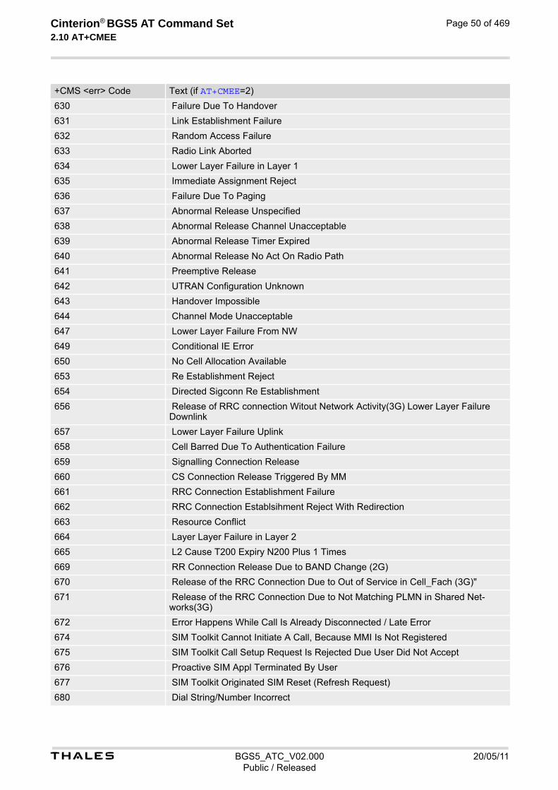
t BGS5_ATC_V02.000 20/05/11Public / Released
Cinterion® BGS5 AT Command Set 2.10 AT+CMEE
Page 50 of 469
630 Failure Due To Handover
631 Link Establishment Failure
632 Random Access Failure
633 Radio Link Aborted
634 Lower Layer Failure in Layer 1
635 Immediate Assignment Reject
636 Failure Due To Paging
637 Abnormal Release Unspecified
638 Abnormal Release Channel Unacceptable
639 Abnormal Release Timer Expired
640 Abnormal Release No Act On Radio Path
641 Preemptive Release
642 UTRAN Configuration Unknown
643 Handover Impossible
644 Channel Mode Unacceptable
647 Lower Layer Failure From NW
649 Conditional IE Error
650 No Cell Allocation Available
653 Re Establishment Reject
654 Directed Sigconn Re Establishment
656 Release of RRC connection Witout Network Activity(3G) Lower Layer Failure Downlink
657 Lower Layer Failure Uplink
658 Cell Barred Due To Authentication Failure
659 Signalling Connection Release
660 CS Connection Release Triggered By MM
661 RRC Connection Establishment Failure
662 RRC Connection Establsihment Reject With Redirection
663 Resource Conflict
664 Layer Layer Failure in Layer 2
665 L2 Cause T200 Expiry N200 Plus 1 Times
669 RR Connection Release Due to BAND Change (2G)
670 Release of the RRC Connection Due to Out of Service in Cell_Fach (3G)"
671 Release of the RRC Connection Due to Not Matching PLMN in Shared Net-works(3G)
672 Error Happens While Call Is Already Disconnected / Late Error
674 SIM Toolkit Cannot Initiate A Call, Because MMI Is Not Registered
675 SIM Toolkit Call Setup Request Is Rejected Due User Did Not Accept
676 Proactive SIM Appl Terminated By User
677 SIM Toolkit Originated SIM Reset (Refresh Request)
680 Dial String/Number Incorrect
+CMS <err> Code Text (if AT+CMEE=2)

t BGS5_ATC_V02.000 20/05/11Public / Released
Cinterion® BGS5 AT Command Set 2.11 AT+CSCS
Page 51 of 469
2.11 AT+CSCS Character Set
AT+CSCS write command informs the BGS5 which character set is used by the TE. This enables the ME to con-vert character strings correctly between TE and ME character sets. Please also refer to Section 1.7, Supported character sets. Note: If ME-TE interface is set to 8-bit operation (AT+ICF) and selected character set is <chset>="GSM" (7-bit), the highest bit will be set to zero.
Syntax
Parameter Description
“GSM“(&F)(P) GSM 7 bit default alphabet (3GPP TS 23.038 [33], Subclause 6.2.1).
“UCS2“ 16-bit universal multiple-octet coded character set (ISO-10646 [12]). UCS2 character strings are converted to hexadecimal numbers in the range 0000 to FFFF; e.g. "004100620063" equates to three 16-bit characters with decimal values 65, 98 and 99.
Test Command
AT+CSCS=?Response(s)
+CSCS: (list of supported<chset>s)OK
Read Command
AT+CSCS?Response(s)
+CSCS: <chset>OK
Write Command
AT+CSCS=<chset>Response(s)
OKERROR+CME ERROR: <err>
PIN Last Reference(s)
- + - 3GPP TS 27.007 [43]
<chset>(str)

t BGS5_ATC_V02.000 20/05/11Public / Released
Cinterion® BGS5 AT Command Set 2.12 AT^SCFG
Page 52 of 469
2.12 AT^SCFG Extended Configuration Settings
AT^SCFG can be used to query and configure various settings of the BGS5. AT^SCFG read command returns a list of all supported parameters and their current values. AT^SCFG write command queries a configuration parameter (if no value is entered) or sets its value(s). Input of parameter names is always coded in GSM character set, parameter values are expected to be given as specified via AT+CSCS.
SyntaxTest Command
AT^SCFG=?Response(s)
^SCFG: "Call/ECC", (list of supported <ecc>s)^SCFG: "GPIO/mode/ASC1", (list of supported <g_mode>s)^SCFG: "GPIO/mode/DAI", (list of supported <g_mode>s)^SCFG: "GPIO/mode/DCD0", (list of supported <g_mode>s)^SCFG: "GPIO/mode/DSR0", (list of supported <g_mode>s)^SCFG: "GPIO/mode/DTR0", (list of supported <g_mode>s)^SCFG: "GPIO/mode/FSR", (list of supported <g_mode>s)^SCFG: "GPIO/mode/PULSE", (list of supported <g_mode>s)^SCFG: "GPIO/mode/PWM", (list of supported <g_mode>s)^SCFG: "GPIO/mode/RING0", (list of supported <g_mode>s)^SCFG: "GPIO/mode/SPI", (list of supported <g_mode>s)^SCFG: "GPIO/mode/SYNC", (list of supported <g_mode>s)^SCFG: "GPRS/AutoAttach", (list of supported <gaa>s)^SCFG: "MEopMode/SoR", (list of supported <SoR mode>s)^SCFG: "Ident/Manufacturer", (max. string length of <manufacturer>)^SCFG: "Ident/Product", (max. string length of <product>)^SCFG: "MEShutdown/Fso", (list of supported <fso>s)^SCFG: "MEShutdown/sVsup/threshold", (list of supported <vthresh>s)^SCFG: "Radio/Band", (list of supported <rba>s), (list of supported <rbe>s)^SCFG: "Radio/OutputPowerReduction", (list of supported <ropr>s)^SCFG: "Serial/Interface/Allocation", (list of supported <curSerialIfcAlloc>s), (list of supported <reqSerialIfcAlloc>s)^SCFG: "Serial/USB/DDD" , (list of supported <deviceDescr>s) , (list of supported <descrIndex>s) , (max. string length of <langId>) , (max. string length of <vendorId>) , (max. string length of <productId>) , (max. string length of <manufacturer>) , (max. string length of <product>) , (max. string length of <serialNo>) ^SCFG: "Tcp/IRT", (list of supported <tcpIrt>)^SCFG: "Tcp/MR", (list of supported <tcpMr>)^SCFG: "Tcp/OT", (list of supported <tcpOt>)^SCFG: "Tcp/WithURCs", (list of supported <tcpWithUrc>)^SCFG: "Trace/Syslog/OTAP", (list of supported <otapTracer>), (list of supported <uwDevice>), (list of supported <intvalue>), (max. string length of <filename>), (list of supported <logmode>), (list of supported <blockmode>)^SCFG: "URC/Ringline", (list of supported <urcRinglineCfg>s)^SCFG: "URC/Ringline/ActiveTime", (list of supported <urcRinglineDuration>s)^SCFG: "Userware/Autostart", (list of supported <ua>s)^SCFG: "Userware/Autostart/Delay", (list of supported <uad>s)^SCFG: "Userware/DebugMode", (list of supported <userwaremode>)^SCFG: "Userware/Passwd", (max. string length of <upwd>)^SCFG: "Userware/Passwd2", (max. string length of <upwd2>)^SCFG: "Userware/Stdout", (list of supported <uwDevice>), (list of supported <intvalue>), (max. string lengths of <filename>), (list of supported <logmode>), (list of supported <blockmode>)^SCFG: "Userware/Watchdog", (list of supported <wd>)OK
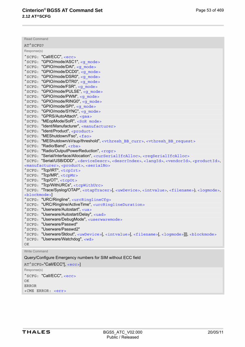
t BGS5_ATC_V02.000 20/05/11Public / Released
Cinterion® BGS5 AT Command Set 2.12 AT^SCFG
Page 53 of 469
Read Command
AT^SCFG?Response(s)
^SCFG: "Call/ECC", <ecc>^SCFG: "GPIO/mode/ASC1", <g_mode>^SCFG: "GPIO/mode/DAI", <g_mode>^SCFG: "GPIO/mode/DCD0", <g_mode>^SCFG: "GPIO/mode/DSR0", <g_mode>^SCFG: "GPIO/mode/DTR0", <g_mode>^SCFG: "GPIO/mode/FSR", <g_mode>^SCFG: "GPIO/mode/PULSE", <g_mode>^SCFG: "GPIO/mode/PWM", <g_mode>^SCFG: "GPIO/mode/RING0", <g_mode>^SCFG: "GPIO/mode/SPI", <g_mode>^SCFG: "GPIO/mode/SYNC", <g_mode>^SCFG: "GPRS/AutoAttach", <gaa>^SCFG: "MEopMode/SoR", <SoR mode>^SCFG: "Ident/Manufacturer", <manufacturer>^SCFG: "Ident/Product", <product>^SCFG: "MEShutdown/Fso", <fso>^SCFG: "MEShutdown/sVsup/threshold", <vthresh_BB_curr>, <vthresh_BB_request>^SCFG: "Radio/Band", <rba>^SCFG: "Radio/OutputPowerReduction", <ropr>^SCFG: "Serial/Interface/Allocation", <curSerialIfcAlloc>, <reqSerialIfcAlloc>^SCFG: "Serial/USB/DDD" , <deviceDescr>, <descrIndex>, <langId>, <vendorId>, <productId>, <manufacturer>, <product>, <serialNo>^SCFG: "Tcp/IRT", <tcpIrt>^SCFG: "Tcp/MR", <tcpMr>^SCFG: "Tcp/OT", <tcpOt>^SCFG: "Tcp/WithURCs", <tcpWithUrc>^SCFG: "Trace/Syslog/OTAP", <otapTracer>[, <uwDevice>, <intvalue>, <filename>), <logmode>, <blockmode>]^SCFG: "URC/Ringline", <urcRinglineCfg>^SCFG: "URC/Ringline/ActiveTime", <urcRinglineDuration>^SCFG: "Userware/Autostart", <ua>^SCFG: "Userware/Autostart/Delay", <uad>^SCFG: "Userware/DebugMode", <userwaremode>^SCFG: "Userware/Passwd"^SCFG: "Userware/Passwd2"^SCFG: "Userware/Stdout", <uwDevice>[, <intvalue>[, <filename>[, <logmode>]]], <blockmode>^SCFG: "Userware/Watchdog", <wd>OK
Write Command
Query/Configure Emergency numbers for SIM without ECC field
AT^SCFG="Call/ECC"[, <ecc>]Response(s)
^SCFG: "Call/ECC", <ecc>OKERROR+CME ERROR: <err>

t BGS5_ATC_V02.000 20/05/11Public / Released
Cinterion® BGS5 AT Command Set 2.12 AT^SCFG
Page 54 of 469
Write Command
Configure ASC1 interface lines RXD1, TXD1, RTS1, CTS1 shared with GPIO16 - GPIO19 lines and SPI lines MOSI, MISO, SPI_CLK and SPI_CS
AT^SCFG="GPIO/mode/ASC1"[, <g_mode>]Response(s)
^SCFG: "GPIO/mode/ASC1", <g_mode>OKERROR+CME ERROR: <err>
Write Command
Configure Digital Audio Interface lines TXDDAI, RXDDAI, TFSDAI, SCLK shared with GPIO20 - GPIO23 lines
AT^SCFG="GPIO/mode/DAI"[, <g_mode>]Response(s)
^SCFG: "GPIO/mode/DAI", <g_mode>OKERROR+CME ERROR: <err>
Write Command
Configure DCD0 line of ASC0 interface shared with GPIO2
AT^SCFG="GPIO/mode/DCD0"[, <g_mode>]Response(s)
^SCFG: "GPIO/mode/DCD0", <g_mode>OKERROR+CME ERROR: <err>
Write Command
Configure DSR0 line of ASC0 interface shared with GPIO3 line
AT^SCFG="GPIO/mode/DSR0"[, <g_mode>]Response(s)
^SCFG: "GPIO/mode/DSR0", <g_mode>OKERROR+CME ERROR: <err>
Write Command
Configure DTR0 line of ASC0 interface shared with GPIO1 line
AT^SCFG="GPIO/mode/DTR0"[, <g_mode>]Response(s)
^SCFG: "GPIO/mode/DTR0", <g_mode>OKERROR+CME ERROR: <err>
Write Command
Configure Fast Shutdown line FST_SHDN shared with GPIO4 line
AT^SCFG="GPIO/mode/FSR"[, <g_mode>]Response(s)
^SCFG: "GPIO/mode/FSR", <g_mode>OKERROR+CME ERROR: <err>

t BGS5_ATC_V02.000 20/05/11Public / Released
Cinterion® BGS5 AT Command Set 2.12 AT^SCFG
Page 55 of 469
Write Command
Configure Impulse Counter line (COUNTER) shared with GPIO8 line
AT^SCFG="GPIO/mode/PULSE"[, <g_mode>]Response(s)
^SCFG: "GPIO/mode/PULSE", <g_mode>OKERROR+CME ERROR: <err>
Write Command
Configure DAC Pulse-Width Modulation lines PWM2 and PWM1 shared with GPIO6 and GPIO7 lines
AT^SCFG="GPIO/mode/PWM"[, <g_mode>]Response(s)
^SCFG: "GPIO/mode/PWM", <g_mode>OKERROR+CME ERROR: <err>
Write Command
Configure RING0 line of ASC0 interface shared with GPIO24 line
AT^SCFG="GPIO/mode/RING0"[, <g_mode>]Response(s)
^SCFG: "GPIO/mode/RING0", <g_mode>OKERROR+CME ERROR: <err>
Write Command
Configure SPI lines MOSI, MISO, SPI_CLK and SPI_CS shared with ASC1 lines and GPIO16 - GPIO19 lines
AT^SCFG="GPIO/mode/SPI"[, <g_mode>]Response(s)
^SCFG: "GPIO/mode/SPI", <g_mode>OKERROR+CME ERROR: <err>
Write Command
Configure Status LED line shared with GPIO5 line
AT^SCFG="GPIO/mode/SYNC"[, <g_mode>]Response(s)
^SCFG: "GPIO/mode/SYNC", <g_mode>OKERROR+CME ERROR: <err>
Write Command
Automatic GPRS attach
AT^SCFG="GPRS/AutoAttach"[, <gaa>]Response(s)
^SCFG: "GPRS/AutoAttach", <gaa>OKERROR+CME ERROR: <err>
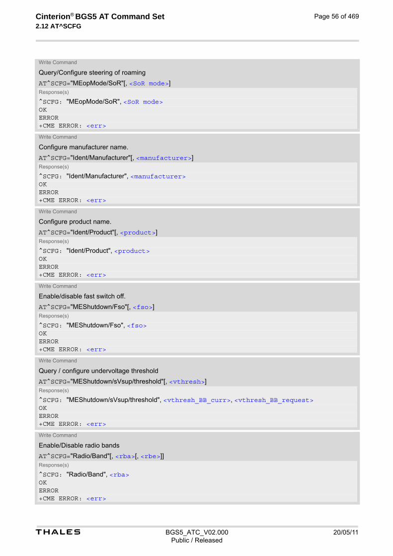
t BGS5_ATC_V02.000 20/05/11Public / Released
Cinterion® BGS5 AT Command Set 2.12 AT^SCFG
Page 56 of 469
Write Command
Query/Configure steering of roaming
AT^SCFG="MEopMode/SoR"[, <SoR mode>]Response(s)
^SCFG: "MEopMode/SoR", <SoR mode>OKERROR+CME ERROR: <err>
Write Command
Configure manufacturer name.
AT^SCFG="Ident/Manufacturer"[, <manufacturer>]Response(s)
^SCFG: "Ident/Manufacturer", <manufacturer>OKERROR+CME ERROR: <err>
Write Command
Configure product name.
AT^SCFG="Ident/Product"[, <product>]Response(s)
^SCFG: "Ident/Product", <product>OKERROR+CME ERROR: <err>
Write Command
Enable/disable fast switch off.
AT^SCFG="MEShutdown/Fso"[, <fso>]Response(s)
^SCFG: "MEShutdown/Fso", <fso>OKERROR+CME ERROR: <err>
Write Command
Query / configure undervoltage threshold
AT^SCFG="MEShutdown/sVsup/threshold"[, <vthresh>]Response(s)
^SCFG: "MEShutdown/sVsup/threshold", <vthresh_BB_curr>, <vthresh_BB_request>OKERROR+CME ERROR: <err>
Write Command
Enable/Disable radio bands
AT^SCFG="Radio/Band"[, <rba>[, <rbe>]]Response(s)
^SCFG: "Radio/Band", <rba>OKERROR+CME ERROR: <err>

t BGS5_ATC_V02.000 20/05/11Public / Released
Cinterion® BGS5 AT Command Set 2.12 AT^SCFG
Page 57 of 469
Write Command
Radio output power reduction
AT^SCFG="Radio/OutputPowerReduction"[, <ropr>]Response(s)
^SCFG: "Radio/OutputPowerReduction", <ropr>OKERROR+CME ERROR: <err>
Write Command
Configure allocation of serial interfaces:
AT^SCFG="Serial/Interface/Allocation"[, <reqSerialIfcAlloc>]Response(s)
^SCFG: "Serial/Interface/Allocation", <curSerialIfcAlloc>, <reqSerialIfcAlloc>OKERROR+CME ERROR: <err>
Write Command
USB Device Descriptor:
AT^SCFG="Serial/USB/DDD" [, <deviceDescr>, [<descrIndex>], [<langId>], <vendorId>, <productId>, [<manufacturer>], [<product>], [<serialNo>]]Response(s)
^SCFG: "Serial/USB/DDD" , <deviceDescr>, <descrIndex>, <langId>, <vendorId>, <productId>, <manufacturer>, <product>, <serialNo>OKERROR+CME ERROR: <err>
Write Command
Configuration of TCP parameter 'InitialRetransmissionTimeout':
AT^SCFG="Tcp/IRT"[, <tcpIrt>]Response(s)
^SCFG: "Tcp/IRT", <tcpIrt>OKERROR+CME ERROR: <err>
Write Command
Configuration of TCP parameter 'MaxRetransmissions':
AT^SCFG="Tcp/MR"[, <tcpMr>]Response(s)
^SCFG: "Tcp/MR", <tcpMr>OKERROR+CME ERROR: <err>
Write Command
Configuration of TCP parameter 'OverallTimeout':
AT^SCFG="Tcp/OT"[, <tcpOt>]Response(s)
^SCFG: "Tcp/OT", <tcpOt>OK

t BGS5_ATC_V02.000 20/05/11Public / Released
Cinterion® BGS5 AT Command Set 2.12 AT^SCFG
Page 58 of 469
ERROR+CME ERROR: <err>
Write Command
Configuration of Internet Service URCs:
AT^SCFG="Tcp/WithURCs"[, <tcpWithUrc>]Response(s)
^SCFG: "Tcp/WithURCs", <tcpWithUrc>OKERROR+CME ERROR: <err>
Write Command
Tracing:
AT^SCFG="Trace/Syslog/OTAP"[, <otapTracer>][, <uwDevice>[, <intvalue>][, <filename>][, <logmode>]][, <blockmode>)]Response(s)
^SCFG: "Trace/Syslog/OTAP", <otapTracer>[, <uwDevice>[, <intvalue>][, <filename>][, <logmode>][, <blockmode>)]]SYSLOG ENABLEDOKERROR+CME ERROR: <err>
Write Command
Subcommand controls the behaviour of the RING line if it is selected for URC signalization.
AT^SCFG="URC/Ringline"[, <urcRinglineCfg>]Response(s)
^SCFG: "URC/Ringline", <urcRinglineCfg>OKERROR+CME ERROR: <err>
Write Command
Subcommand controls duration of active RING line if it is selected for URC signalization.
AT^SCFG="URC/Ringline/ActiveTime"[, <urcRinglineDuration>]Response(s)
^SCFG: "URC/Ringline/ActiveTime", <urcRinglineDuration>OKERROR+CME ERROR: <err>
Write Command
Userware autostart status:
AT^SCFG="Userware/Autostart"[, <upwd>, <ua>]Response(s)
^SCFG: "Userware/Autostart"[, <ua>]OKERROR+CME ERROR: <err>
Write Command (Continued)
Configuration of TCP parameter 'OverallTimeout':
AT^SCFG="Tcp/OT"[, <tcpOt>]Response(s)

t BGS5_ATC_V02.000 20/05/11Public / Released
Cinterion® BGS5 AT Command Set 2.12 AT^SCFG
Page 59 of 469
Write Command
Userware autostart delay:
AT^SCFG="Userware/Autostart/Delay"[, <upwd>, <uad>]Response(s)
^SCFG: "Userware/Autostart/Delay"[, <uad>]OKERROR+CME ERROR: <err>
Write Command
AT^SCFG="Userware/DebugMode"[, <userwaremode>]Response(s)
^SCFG: "Userware/DebugMode"[, <userwaremode>]OKERROR+CME ERROR: <err>
Write Command
Userware configuration password:
AT^SCFG="Userware/Passwd"[, <upwd>old, <upwd>new, <upwd>new]
Response(s)
^SCFG: "Userware/Passwd"OKERROR+CME ERROR: <err>
Write Command
Userware configuration password:
AT^SCFG="Userware/Passwd2"[, <upwd2>old, <upwd2>new, <upwd2>new]
Response(s)
^SCFG: "Userware/Passwd2"OKERROR+CME ERROR: <err>
Write Command
Standard output of userware:
AT^SCFG="Userware/Stdout"[, <uwDevice>[, <intvalue>][, <filename>][, <logmode>]][, <blockmode>)]Response(s)
^SCFG: "Userware/Stdout" , <uwDevice>[, <intvalue>[, <filename>[, <logmode>]]], <blockmode>OKERROR+CME ERROR: <err>
Write Command
Watchdog configuration and control:
AT^SCFG="Userware/Watchdog"[, <wd>]Response(s)
^SCFG: "Watchdog", <wd>OKERROR+CME ERROR: <err>
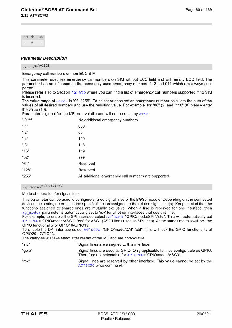
t BGS5_ATC_V02.000 20/05/11Public / Released
Cinterion® BGS5 AT Command Set 2.12 AT^SCFG
Page 60 of 469
Parameter Description
Emergency call numbers on non-ECC SIM
This parameter specifies emergency call numbers on SIM without ECC field and with empty ECC field. The parameter has no influence on the commonly used emergency numbers 112 and 911 which are always sup-ported. Please refer also to Section 7.2, ATD where you can find a list of emergency call numbers supported if no SIM is inserted. The value range of <ecc> is "0"..."255". To select or deselect an emergency number calculate the sum of the values of all desired numbers and use the resulting value. For example, for "08" (2) and "118" (8) please enter the value (10). Parameter is global for the ME, non-volatile and will not be reset by AT&F.
“ 0“(D) No additional emergency numbers
“ 1“ 000
“ 2“ 08
“ 4“ 110
“ 8“ 118
“16“ 119
“32“ 999
“64“ Reserved
“128“ Reserved
“255“ All additional emergency call numbers are supported.
Mode of operation for signal lines
This parameter can be used to configure shared signal lines of the BGS5 module. Depending on the connected devices the setting determines the specific function assigned to the related signal line(s). Keep in mind that the functions assigned to shared lines are mutually exclusive. When a line is reserved for one interface, then <g_mode> parameter is automatically set to 'rsv' for all other interfaces that use this line. For example, to enable the SPI interface select AT^SCFG="GPIO/mode/SPI","std". This will automatically set AT^SCFG="GPIO/mode/ASC1","rsv" for ASC1 (ASC1 lines used as SPI lines). At the same time this will lock the GPIO functionality of GPIO16-GPIO19. To enable the DAI interface select AT^SCFG="GPIO/mode/DAI","std". This will lock the GPIO functionality of GPIO20 - GPIO23. The changes will take effect after restart of the ME and are non-volatile.
“std“ Signal lines are assigned to this interface.
“gpio“ Signal lines are used as GPIO. Only applicable to lines configurable as GPIO. Therefore not selectable for AT^SCFG="GPIO/mode/ASC0".
“rsv“ Signal lines are reserved by other interface. This value cannot be set by the AT^SCFG write command.
PIN Last
- ± -
<ecc>(str)(+CSCS)
<g_mode>(str)(+CSCS)(NV)
t BGS5_ATC_V02.000 20/05/11Public / Released
Cinterion® BGS5 AT Command Set 2.12 AT^SCFG
Page 61 of 469
GPRS with AutoAttach
This parameter can be used to control whether the ME will perform a GPRS attach immediately after power-up and registering to the network or not. If the setting is changed to "enabled" and the ME is not attached yet, it will not initiate an attach immediately but after the next power-up and registration to the network. Parameter is global for all interfaces, non-volatile and will not be reset by AT&F.
“disabled“ GPRS auto attach is disabled
“enabled“(D) GPRS auto attach is enabled
Manufacturer name
Setting can be used to configure the name of the manufacturer which is displayed with the commands ATI and AT+CGMI. Maximal length of the Manufacturer name is 25 characters (or less if you use multibyte characters).
“Cinterion“(D)
Product name
Setting can be used to configure the name of the product which is displayed with the commands ATI and AT+CGMM. Maximal length of the product name is 25 characters (or less if you use multibyte characters).
“BGS5“(D)
Enable/disable fast switch off
This parameter configures a fast ME switch off, i.e., a shutdown without network deregistration. If enabled, the ME can be shut down without network deregistration by using either the AT command AT^SMSO or the hardware line FAST_SHTDWN. For further details please refer to [2]. Please take great care before changing the fast switch off mode. Factory setting is <fso>="0". Parameter <fso> is global for all interfaces, non-volatile and will not be reset by AT&F.
“0“(D) Fast ME switch off is disabled. AT^SMSO performs an orderly ME shutdown and issues the "^SHUTDOWN" URC. Triggering the FAST_SHTDWN line has no effect.
“1“ Fast ME switch off enabled. AT^SMSO performs the fast switch off and does not issue any reply, e.g., OK, ERROR or any "^SHUTDOWN" URC. Triggering the FAST_SHTDWN line will start the fast shutdown procedure.
Threshold offset index
The undervoltage threshold defined for the baseband (BB) is calculated for max. 400 mV voltage drops during transmit burst. Power supply sources for BGS5 applications shall be designed to tolerate 400 mV voltage drops without crossing the lower limit of 3.3 V (BB). For BGS5 applications operating at the limit of the allowed toler-ance the default undervoltage threshold may be adapted by subtracting an offset. New settings take effect after restart.
“-4“ 3.1V
“0“(D) 3.3 V (no offset)
The current BB undervoltage threshold
“-4“ 3.1V
“0“(D) 3.3 V (no offset)
<gaa>(str)(+CSCS)(NV)
<manufacturer>(str)(NV)
<product>(str)(NV)
<fso>(str)(+CSCS)
<vthresh>(str)(NV)
<vthresh_BB_curr>(str)

t BGS5_ATC_V02.000 20/05/11Public / Released
Cinterion® BGS5 AT Command Set 2.12 AT^SCFG
Page 62 of 469
The BB undervoltage threshold after next restart
“-4“ 3.1V
“0“(D) 3.3 V (no offset)
Steering of roaming:
The parameter enables or disables the steering of roaming behaviour. Changes will be active with next start of the ME.
“off“(D) Steering of roaming is disabled
“on“ Steering of roaming is enabled for BGS5.
Allowed radio band(s)
Parameter determines frequency band usage of the ME. Please note that the band selection implementation of BGS5 is based on a single band group that includes all frequency bands it is capable to use. This enables the ME to easily find a suitable network in any country around the world, no matter which frequency bands or band combinations and access technologies are present in a particular area. Factory default of <rba> is the combination of all available bands meaning that all supported bands are allowed. If AT+COPS equals "0" (automatic mode) this solution allows the subscriber to take advantage of a full-featured automatic network selection when trying to register. Therefore, changes to the band configuration are recommended only if the subscriber wishes to restrict the allowed bands to a specific band or band combination, in particular to speed up the network search, and thus, to reduce the power consumption. In such case, <rba> may be one of the supported single values listed below or the sum of the values of all desired bands. For example, for GSM 900 MHz (1) and GSM 1800 MHz (2) please enter the value 3 (=1 + 2). When changing the <rba> value you can use the additional <rbe> parameter to make the changes take effect immediately without reboot being required (<rbe>="1") or after reboot only (<rbe>="0"). If you wish to configure a specific band or band configuration take care that the selected value complies with the <AcT> value selected with AT+COPS. Otherwise, if the settings of <rba> and <AcT> are incompatible all bands supported by BGS5 will be enabled after power-up.
“1“ GSM 900
“2“ GSM 1800
“4“ GSM 850
“8“ GSM 1900
Radio/Band: Set frequency band(s) immediately effective
Parameter is not supported and kept for compatibility reasons only.
“0“ <rba> takes effect after next restart.
“1“ <rba> takes effect immediately and will also be effective after next restart.
<vthresh_BB_request>(str)
<SoR mode>(str)(+CSCS)(NV)
<rba>(str)(+CSCS)
<rbe>(str)
t BGS5_ATC_V02.000 20/05/11Public / Released
Cinterion® BGS5 AT Command Set 2.12 AT^SCFG
Page 63 of 469
Radio Output Power Reduction
For GPRS multislot scenarios, the module reduces its output power according to 3GPP 45.005 section 4.1.1. The amount of output power reduction (i.e. the used power profile) is controllable via AT command using "AT^SCFG=Radio/OutputPowerReduction". The configuration is stored non-volatile. The new power setting will be read after next power up.
“0“ No power reduction with GMSK
“1“ 2 dB power reduction with GMSK (with 4 Tx)
“2“ 4 dB power reduction with GMSK (with 4 Tx)
“3“ 6 dB power reduction with GMSK (with 4 Tx)
“4“(D) Max. power reduction for GSMK
Initial Retransmission Timeout (IRT)
"1"..."3"(D)..."60" This parameter determines the time (in seconds) the TCP/IP stack will wait before starting the first retransmission of packets during the initial connection establishment phase. The TCP protocol ensures the retransmission of packets several times at increasing intervals until some upper limit is reached. This mechanism prevents packet loss and serious congestion problems. In addition, the parameters <tcpMr> and <tcpOt> can be set to further optimize this mechanism for special conditions depending on the mobile network. Parameter is global for the ME and non-volatile. Use of default value is recom-mended. If changed the new value takes effect the next time you start an Inter-net service with AT^SISO.
Maximum Number of Retransmissions (MR)
"1"..."10"(D)..."30" This parameter determines the maximum number of times to retransmit TCP packets. The value set with <tcpMr> will be assumed as default for the <srvParm-Tag> "tcpMR" when a new service profile is created with AT^SISS. In each service profile, you can set another "tcpMR" value which has precedence over the global value set with AT^SCFG. Existing service profiles are not affected when you change the global value via AT^SCFG. Parameter is global for the ME and non-volatile. Use of default value is recom-mended.
Overall TCP Timer for outstanding connections (tcpOT)
"1"..."6000"(D) This parameter specifies the number of seconds to wait before closing a con-nection if TCP/IP packets are not acknowledged. Setting the maximum value is practically equivalent to deactivating the tcpOT mechanism because the maximum time would never be reached by the TCP/IP stack. The value set with <tcpOt> will be assumed as default for the <srvParm-Tag> "tcpOT" when a new service profile is created with AT^SISS. However, in each service profile, you can set another "tcpOT" value which has prece-dence over the global value set with AT^SCFG. Existing service profiles are not affected when you change the global value via AT^SCFG. Parameter is non-volatile. Use of default value is recommended.
<ropr>(str)(+CSCS)(NV)
<tcpIrt>(str)(+CSCS)
<tcpMr>(str)(+CSCS)
<tcpOt>(str)(+CSCS)
t BGS5_ATC_V02.000 20/05/11Public / Released
Cinterion® BGS5 AT Command Set 2.12 AT^SCFG
Page 64 of 469
URC mode or polling mode for Internet service commands
This parameter enables or disables the presentation of the following URCs related to Internet service com-mands: "^SISR" URC, "^SISW" URC and "^SIS" URC for parameter <urcCause>=0 (Internet service events). "^SIS" URCs with <urcCause>=1 or 2 used to indicate incoming Socket connections are always enabled. Parameter is global for the ME and non-volatile.
“on“(D) Enable URCs related to Internet service commands. Throughout the Chapter "Internet Service AT Commands" the mode is also referred to as URC mode.
“off“ Disable URCs related to Internet service commands. This requires the TE to employ polling techniques when using the Internet ser-vice AT commands: The TE is responsible to retrieve all status information needed to control an Internet session. The method is referred to as polling mode.
OTAP tracer
This parameter enables a trace output of the Over The Air procedure. The tracer is useful for obtaining additional information when setting up an OTAP scenario. The output is provided on the interface configured with <uwDe-vice> (given <uwDevice> has to differ from currently used one) or if omitted (for compatibility reason only) on the interface on which the command was entered. While the tracer is enabled the interface is used for trace out-put only, meaning that no AT commands can be entered. The tracer will be switched off only by a reset of the ME, e.g. after a completed OTAP procedure or if disabled by setting parameter to "0".
“0“ Disable OTAP tracer.
“1“ Enable OTAP tracer.
Current Serial Interface Allocation
Parameter shows the current allocation of the serial interfaces. Configuration may be overwritten by the GPIO configuration done by the AT^SCFG parameters "GPIO/mode/...".
“0“(D) AT commands are usable on ASC0 and USB0; BB-Trace is available on USB1. Please note that this configuration should be used for factory purposes only. Before productive usage you need to switch to another configuration.
“1“ AT commands are usable on ASC0, ASC1 and USB0; BB-Trace is available on USB1.
“2“ AT commands are usable on ASC0 and USB[01]; BB-Trace is available on ASC1.
Requested Serial Interface Allocation
Parameter allows to configure the allocation of the serial interfaces. On powerup the requested configuration is the same as the current configuration. If the requested configuration becomes different to the current configura-tion, then it becomes active after restart.
“0“ AT commands are usable on ASC0 and USB0; BB-Trace is available on USB1. Please note that this configuration should be used for factory purposes only.
“1“ AT commands are usable on ASC0, ASC1 and USB0; BB-Trace is available on USB1.
“2“ AT commands are usable on ASC0 and USB[01]; BB-Trace is available on ASC1.
<tcpWithUrc>(str)(+CSCS)
<otapTracer>(str)(+CSCS)
<curSerialIfcAlloc>(str)(+CSCS)(NV)
<reqSerialIfcAlloc>(str)(+CSCS)

t BGS5_ATC_V02.000 20/05/11Public / Released
Cinterion® BGS5 AT Command Set 2.12 AT^SCFG
Page 65 of 469
Device Descriptor
This parameter determines whether to use the ME's standard USB Device Descriptor configuration (default) or a Device Descriptor configuration customized by the Customer Application manufacturer. Parameter is global, stored non-volatile in ME and not reset by AT&F. Setting takes effect after next USB inter-face enumeration.
“0“(D) Standard USB Device Descriptor of the ME. If <deviceDescr>=0 is set all other parameters related to "Serial/USB/DDD" cannot be changed. For use in a Windows environment, the "usbmodem.inf" file delivered with BGS5 shall be present. Note that whenever the BGS5 firmware is updated over the USB interface the ME's standard configuration must be present. Therefore, before starting a BGS5 firmware download be sure that <deviceDescr>=0 is activated and, under Windows, the ME's "usbmodem.inf" file can be found. Remember to restart the ME after reverting to <deviceDescr>=0 and before starting the firmware download.
“1“ Customer specific USB Device Descriptor. If <deviceDescr>=1 is set all other parameters related to "Serial/USB/DDD" can be changed. Customizing the USB Device Descriptor configuration requires a unique Ven-dor ID obtained from the USB Implementers Forum. For information please refer to http://www.usb.org. For use under Windows a customized INF file for the USB modem must be present. An easy way to create this file is copying the ME's "usbmodem.inf" file and overwriting the equivalent values changed with AT^SCFG, usually at least the Vendor ID, Product ID and, optionally, the manufacturer string. This is because the strings given for the customized "Serial/USB/DDD" parameters must be identical with those contained in the INF file.
Descriptor Index
“0“(D) Not to be changed. Use always 0.
Language ID
Please refer to USB.ORG [49] to find the language IDs currently defined for USB devices. If parameter <lan-gId> is not specified, the default value of the ME's standard USB Device Descriptor configuration applies (US English). Parameter is global, stored non-volatile in ME and not reset by AT&F. Setting takes effect after next USB inter-face enumeration. Parameter shall be given in HEX format, maximum 4 characters. Please note that this parameter is effective only if the customized Device Descriptor <deviceDescr>=1 is enabled.
Vendor ID
This parameter represents the Vendor ID obtained from the USB Implementers Forum. The Vendor ID will, together with the Product ID, be transmitted to the host during USB enumeration. The given Vendor ID must be included in the INF file needed for Windows. Parameter is global, stored non-volatile in ME and not reset by AT&F. Setting takes effect after next USB inter-face enumeration. Parameter shall be given in HEX format, maximum 4 characters. Please note that this parameter is effective only if the customized Device Descriptor <deviceDescr>=1 is enabled.
<deviceDescr>(str)(+CSCS)
<descrIndex>(str)(+CSCS)
<langId>(str)(+CSCS)
<vendorId>(str)(+CSCS)
t BGS5_ATC_V02.000 20/05/11Public / Released
Cinterion® BGS5 AT Command Set 2.12 AT^SCFG
Page 66 of 469
Product ID
Product ID (PID) defined by the Customer Application manufacturer to identify the USB device. The Product ID will, together with the Vendor ID, be transmitted to the host during USB enumeration. The given Product ID must be included in the INF file needed for Windows. Parameter is global, stored non-volatile in ME and not reset by AT&F. Setting takes effect after next USB inter-face enumeration. Parameter shall be given in HEX format, maximum 4 characters. Please note that this parameter is effective only if the customized Device Descriptor <deviceDescr>=1 is enabled.
Manufacturer name
Optional manufacturer string defined by the Customer Application manufacturer. If specified with <manufac-turer> the same string shall be included in the INF file needed for Windows. Parameter is global, stored non-volatile in ME and not reset by AT&F. Setting takes effect after next USB inter-face enumeration. Parameter length: maximum 63 characters. Please note that this parameter is effective only if the customized Device Descriptor <deviceDescr>=1 is enabled.
Product string
Optional product name defined by the Customer Application manufacturer. If specified with <product> it is rec-ommended to include the same string into the INF file. Parameter is global, stored non-volatile in ME and not reset by AT&F. Setting takes effect after next USB inter-face enumeration. Parameter length: maximum 63 characters. Please note that this parameter is effective only if the customized Device Descriptor <deviceDescr>=1 is enabled.
Device's serial number
Optional serial number. Empty string if not used, like in the case of the ME'S standard USB Device Descriptor configuration. A serial number has several advantages. For example, it enables the host to assign the same virtual COM port to same USB device even though the device is connected to another USB port. This eliminates the need for the host to load the driver again. Parameter is global, stored non-volatile in ME and not reset by AT&F. Setting takes effect after next USB inter-face enumeration. If parameter <serialNo> is not specified, the default value of ME's standard USB Device Descriptor applies. Parameter length: maximum 4 characters. Please note that this parameter is effective only if the customized Device Descriptor <deviceDescr>=1 is enabled.
Parameter specifies the ring line to be used for signaling URCs both for idle interface and while interface is reserved, i.e. while busy on AT command execution or data transmission. This functionality serves to fine-tune the conditions under which the ME signals service request to the TE. For details about URC presentation and related hardware signalization refer to Section 1.8, Unsolicited Result
<productId>(str)(+CSCS)
<manufacturer>(str)(+CSCS)
<product>(str)(+CSCS)
<serialNo>(str)(+CSCS)
<urcRinglineCfg>(str)(+CSCS)(NV)
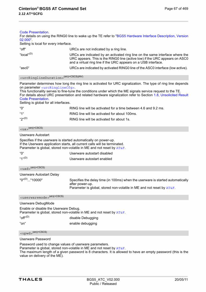
t BGS5_ATC_V02.000 20/05/11Public / Released
Cinterion® BGS5 AT Command Set 2.12 AT^SCFG
Page 67 of 469
Code Presentation. For details on using the RING0 line to wake up the TE refer to "BGS5 Hardware Interface Description, Version 02.000". Setting is local for every interface.
“off“ URCs are not indicated by a ring line.
“local“(D) URCs are indicated by an activated ring line on the same interface where the URC appears. This is the RING0 line (active low) if the URC appears on ASC0 and a virtual ring line if the URC appears on a USB interface.
“asc0“ URCs are indicated by activated RING0 line of the ASC0 interface (low active).
Parameter determines how long the ring line is activated for URC signalization. The type of ring line depends on parameter <urcRinglineCfg>. This functionality serves to fine-tune the conditions under which the ME signals service request to the TE. For details about URC presentation and related hardware signalization refer to Section 1.8, Unsolicited Result Code Presentation. Setting is global for all interfaces.
“0“ RING line will be activated for a time between 4.6 and 9.2 ms.
“1“ RING line will be activated for about 100ms.
“2“(D) RING line will be activated for about 1s.
Userware Autostart
Specifies if the userware is started automatically on power-up. If the Userware application starts, all current calls will be terminated. Parameter is global, stored non-volatile in ME and not reset by AT&F.
“0“ Userware autostart disabled
“1“(D) Userware autostart enabled
Userware Autostart Delay
"0"(D)..."10000" Specifies the delay time (in 100ms) when the userware is started automatically after power-up. Parameter is global, stored non-volatile in ME and not reset by AT&F.
Userware DebugMode
Enable or disable the Userware Debug. Parameter is global, stored non-volatile in ME and not reset by AT&F.
“off“(D) disable Debugging
“on“ enable debugging
Userware Password
Password used to change values of userware parameters. Parameter is global, stored non-volatile in ME and not reset by AT&F. The maximum length of a given password is 8 characters. It is allowed to have an empty password (this is the value on delivery of the ME).
<urcRinglineDuration>(str)(+CSCS)(NV)
<ua>(str)(+CSCS)
<uad>(str)(+CSCS)
<userwaremode>(str)(+CSCS)
<upwd>(str)(+CSCS)

t BGS5_ATC_V02.000 20/05/11Public / Released
Cinterion® BGS5 AT Command Set 2.12 AT^SCFG
Page 68 of 469
Parameter must be enclosed in quotation marks, regardless whether the password is given or empty. See exam-ple below. CAUTION: Be careful not to lose the password. There is no way to reset or recover a forgotten password or to obtain a new password from the manufacturer.
Userware Password2
Password used to change values of userware parameters. Parameter is global, stored non-volatile in ME and not reset by AT&F. The maximum length of a given password is 8 characters. It is allowed to have an empty password (this is the value on delivery of the ME). Parameter must be enclosed in quotation marks, regardless whether the password is given or empty. See exam-ple below. CAUTION: Be careful not to lose the password. There is no way to reset or recover a forgotten password or to obtain a new password from the manufacturer.
Userware Mode
Parameter is global, volatile and not reset by AT&F.
[“normal“] Userware is started by AT command or autostart option.
“debug“ Userware is started by debugger on host side.
“test“ Userware is loaded from test server.
Userware output device
Parameter specifies the device to be used for the userware's standard output System.out. The selected device must be supported by the hardware.
“NULL“(D) Discard output data.
“ASC0“ Output of "System.out" is routed to the first serial interface. The interface is shared between internal "CommConnection" and "Sys-tem.out". The baud rate set for "CommConnection" applies also to "Sys-tem.out".
“ASC1“ Output of "System.out" is routed to the second serial interface. The interface is shared between internal "CommConnection" and "Sys-tem.out". The baud rate set for "CommConnection" applies also to "Sys-tem.out".
“USB“ Output of "System.out" is routed to the Universal Serial Bus interface.
“USB1“ Output of "System.out" is routed to the Universal Serial Bus interface 1.
“UDP“ Output of "System.out" is routed to a UDP socket. The parameter requires that the port number be given with <intvalue>. "UDP" is intended only for use with the Userware IDE and will be set automat-ically each time you start the debugging emulator of the BGS5 (on-device debugging). Closing the debugger causes the ME to reboot and automatically resets the <uwDevice> value last selected. This eliminates any need for man-ually setting "UDP" with AT^SCFG, and, besides, allows you to select another "System.out" target to be used when not debugging. Due to this, the value "UDP" is volatile unlike all other <uwDevice> values, and switching to "UDP" is not supported while Userware is running.
“FILE“ Output of "System.out" is written into a file. Requires additional parameters <intvalue>, <filename> and <logmode>. Because excessive writing to the ME's flash file system decreases the life time of the flash memory, it is rec-ommended to use the "FILE" device only during development phases.
“SYSTEM“ For internal use only.
<upwd2>(str)(+CSCS)
<umode>(str)(+CSCS)
<uwDevice>(str)(+CSCS)(NV)

t BGS5_ATC_V02.000 20/05/11Public / Released
Cinterion® BGS5 AT Command Set 2.12 AT^SCFG
Page 69 of 469
This parameter is required only if parameter <uwDevice> for the Userware System.out is set to "UDP" or "FILE". Parameter is global, stored non-volatile in ME and not reset by AT&F.
"1"..."65535" If <uwDevice>= "UDP": UDP port number. It is recommended to use a num-ber greater than 1023. If <uwDevice>= "FILE": Size of the log file in bytes, values less then 1024 are not supported.
This parameter is required only if parameter <uwDevice> for the Userware System.out is set to "FILE". It spec-ifies the absolute path and the file name of the log. The local Flash File system is identified by: "A:", directory separator is "/" (002Fh). The underline character "_" (005Fh) is not supported. The log is split into two concatenated files, each using half of the entire log size set with parameter <intvalue>. Each file name consists of the name specified with parameter <filename> and the numeric extension "0" or "1" automatically appended, for example "a:/java/log.txt.0" for the first part of the log and "a:/java/log.txt.1" for the second part. When the first log file reaches half of the log size, the System.out is written to the second file. When the second file is used up, the ME starts to overwrite the first one. Parameter is global, stored non-volatile in ME and not reset by AT&F. Parameter length: maximum 125 characters.
This parameter is required only if parameter <uwDevice> for the Userware System.out is set to "FILE". The parameter selects the mode of writing System.out data to file. Parameter is global, stored non-volatile in ME and not reset by AT&F.
“buffered“(D) Uses a buffer and a timer and acts like a write cache.
“secure“ Writes all output data byte by byte to the file.
The parameter defines, how the Stdout strings are truncated. Parameter is global, stored non-volatile in ME and not reset by AT&F.
[“off“](D) Stdout strings are truncated if output device handling reaches its transmission capability.
“on“ Stdout strings are never truncated. If output device buffer is full, the Java VM is waiting until memory becomes free again. This handling may slow down the VM when a lot of outputs are created, even a full stop of the VM is possible, if the used device is in flow control. Please use this option very carefully, and never in a production environment.
Watchdog configuration and control
This parameter is used to configure the watchdog behavior. The action triggered by the watchdog takes place without regard of network registration, file system operation and other ongoing actions (hard reset). Parameter is global for all interfaces, non-volatile and will not be reset by AT&F.
“0“(D) Watchdog "do nothing". The watchdog has no effect.
“1“ Watchdog "re-start". The watchdog will reboot the system.
“2“ Watchdog "shutdown". The watchdog will switch off the system.
<intvalue>(str)(+CSCS)
<filename>(str)(+CSCS)(NV)
<logmode>(str)(+CSCS)
<blockmode>(str)(+CSCS)
<wd>(str)(+CSCS)
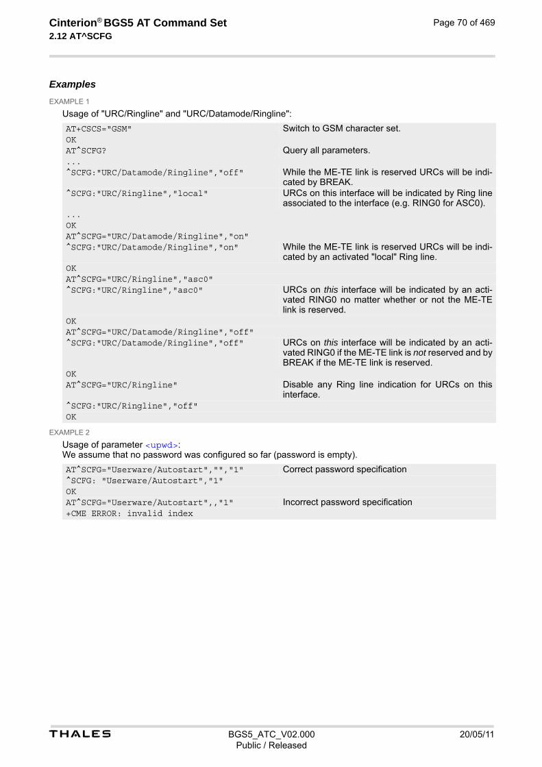
t BGS5_ATC_V02.000 20/05/11Public / Released
Cinterion® BGS5 AT Command Set 2.12 AT^SCFG
Page 70 of 469
Examples EXAMPLE 1
Usage of "URC/Ringline" and "URC/Datamode/Ringline":
EXAMPLE 2
Usage of parameter <upwd>: We assume that no password was configured so far (password is empty).
AT+CSCS="GSM" Switch to GSM character set.OKAT^SCFG? Query all parameters....^SCFG:"URC/Datamode/Ringline","off" While the ME-TE link is reserved URCs will be indi-
cated by BREAK.^SCFG:"URC/Ringline","local" URCs on this interface will be indicated by Ring line
associated to the interface (e.g. RING0 for ASC0)....OKAT^SCFG="URC/Datamode/Ringline","on"^SCFG:"URC/Datamode/Ringline","on" While the ME-TE link is reserved URCs will be indi-
cated by an activated "local" Ring line.OKAT^SCFG="URC/Ringline","asc0"^SCFG:"URC/Ringline","asc0" URCs on this interface will be indicated by an acti-
vated RING0 no matter whether or not the ME-TE link is reserved.
OKAT^SCFG="URC/Datamode/Ringline","off"^SCFG:"URC/Datamode/Ringline","off" URCs on this interface will be indicated by an acti-
vated RING0 if the ME-TE link is not reserved and by BREAK if the ME-TE link is reserved.
OKAT^SCFG="URC/Ringline" Disable any Ring line indication for URCs on this
interface.^SCFG:"URC/Ringline","off"OK
AT^SCFG="Userware/Autostart","","1" Correct password specification^SCFG: "Userware/Autostart","1"OKAT^SCFG="Userware/Autostart",,"1" Incorrect password specification+CME ERROR: invalid index
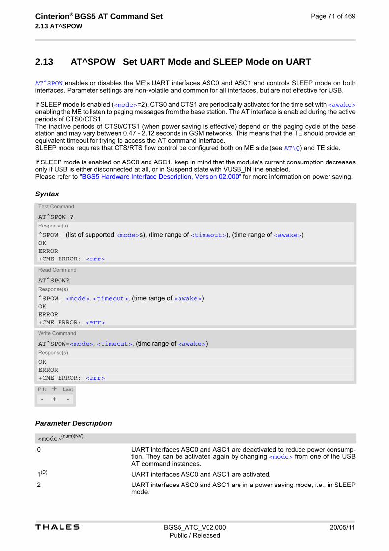
t BGS5_ATC_V02.000 20/05/11Public / Released
Cinterion® BGS5 AT Command Set 2.13 AT^SPOW
Page 71 of 469
2.13 AT^SPOW Set UART Mode and SLEEP Mode on UART
AT^SPOW enables or disables the ME's UART interfaces ASC0 and ASC1 and controls SLEEP mode on both interfaces. Parameter settings are non-volatile and common for all interfaces, but are not effective for USB. If SLEEP mode is enabled (<mode>=2), CTS0 and CTS1 are periodically activated for the time set with <awake> enabling the ME to listen to paging messages from the base station. The AT interface is enabled during the active periods of CTS0/CTS1. The inactive periods of CTS0/CTS1 (when power saving is effective) depend on the paging cycle of the base station and may vary between 0.47 - 2.12 seconds in GSM networks. This means that the TE should provide an equivalent timeout for trying to access the AT command interface. SLEEP mode requires that CTS/RTS flow control be configured both on ME side (see AT\Q) and TE side. If SLEEP mode is enabled on ASC0 and ASC1, keep in mind that the module's current consumption decreases only if USB is either disconnected at all, or in Suspend state with VUSB_IN line enabled. Please refer to "BGS5 Hardware Interface Description, Version 02.000" for more information on power saving.
Syntax
Parameter Description
0 UART interfaces ASC0 and ASC1 are deactivated to reduce power consump-tion. They can be activated again by changing <mode> from one of the USB AT command instances.
1(D) UART interfaces ASC0 and ASC1 are activated.
2 UART interfaces ASC0 and ASC1 are in a power saving mode, i.e., in SLEEP mode.
Test Command
AT^SPOW=?Response(s)
^SPOW: (list of supported <mode>s), (time range of <timeout>), (time range of <awake>)OKERROR+CME ERROR: <err>
Read Command
AT^SPOW?Response(s)
^SPOW: <mode>, <timeout>, (time range of <awake>)OKERROR+CME ERROR: <err>
Write Command
AT^SPOW=<mode>, <timeout>, (time range of <awake>)Response(s)
OKERROR+CME ERROR: <err>
PIN Last
- + -
<mode>(num)(NV)

t BGS5_ATC_V02.000 20/05/11Public / Released
Cinterion® BGS5 AT Command Set 2.13 AT^SPOW
Page 72 of 469
0(D) Value 0 applies only to <mode>=0 or 1. Note that the AT^SPOW? read com-mand response value of <awake> is always equal 0 when power saving is off.
3...65535 In SLEEP mode (<mode>=2), time in milliseconds the ME remains awake after the last sent character. Minimum value: 3 ms, recommended 1000 ms. <timeout> values below 3 are denied with ERROR. <timeout> value cannot be lower than <awake> value. If <timeout> is set to lower value than <awake> it will be automatically set to be equal <awake>.
0(D) Value 0 applies only to <mode>=0 or 1. Note that the AT^SPOW? read com-mand response value of <awake> is always equal 0 when power saving is off.
3...255 In SLEEP mode (<mode>=2), active period of CTS0/CTS1 in milliseconds when ME is listening to paging messages from the base station and the AT command interface is enabled. Minimum and recommended value: 3 ms. Lower <awake> values are denied with ERROR. Setting a higher value is recommended only when the TE flow control is too slow.
<timeout>(num)(NV)
<awake>(num)(NV)

Cinterion® BGS5 AT Command Set 3. Status Control Commands
t BGS5_ATC_V02.000 20/05/11Public / Released
Page 73 of 469
3. Status Control Commands
The AT Commands described in this chapter allow the external application to obtain various status information from the BGS5.
3.1 AT+CEER Extended Error Report
AT+CEER returns an extended error report regarding the reason of the last
• call release
• failure to set up a call (both mobile originated or terminated)
• failure to modify a call by using Supplementary Services
• failed attempt to activate, register, query, deactivate or deregister a Supplementary Service
• unsuccessful Packet Domain attach or unsuccessful PDP context activation
• Packet Domain detach or PDP context deactivation
The extended error report consists of 1 line showing categorized error causes. Abbreviations used for these cat-egories: CC = Call Control, SM = Session Management, SS = Supplementary Services. Examples: +CEER: "No report available" +CEER: "CC setup error", 16, "Normal call clearing" +CEER: "CC setup error",1,"Unassigned (unallocated) number" +CEER: "SM detach",0,"No cause information available"
SyntaxTest Command
AT+CEER=?Response(s)
OKERROR+CME ERROR: <err>
Exec Command
AT+CEERResponse(s)
In case of CC and SM categories:+CEER: <category>[, <cause>, <description>]In case of SS category network error cause and network GSM cause:+CEER: <category>, <cause>In case of SS category network reject cause:+CEER: <category>, <tag>, <cause>OKERROR+CME ERROR: <err>
Write Command
AT+CEER=<reset>Response(s)
OKERROR+CME ERROR

t BGS5_ATC_V02.000 20/05/11Public / Released
Cinterion® BGS5 AT Command Set 3.1 AT+CEER
Page 74 of 469
Parameter Description
Category given as one of the following strings: "No report available" "CC setup error" "CC modification error" "CC release" "SM attach error" "SM detach" "SM activation error" "SM deactivation" "SS network error cause" "SS network reject cause" "SS network GSM cause"
Cause for last call release or error as number code. Sent by network or internally.
Verbose string containing the textual representation of the cause.
Numeric value indicating an SS Reject code.
0 Reset the extended error report to initial value.
3.1.1 Release causes for L3 Call Control (CC)
See also 3GPP TS 24.008 [38], section 10.5.4.11 "Cause". All values greater than 255 are internal values.
PIN Last Reference(s)
- + - 3GPP TS 27.007 [43] 3GPP TS 24.008 [38]
<category>(str)
<cause>(num)
<description>(str)
<tag>(num)
<reset>(num)
<cause> <description>
Normal class
1 Unassigned (unallocated) number
3 No route to destination
6 Channel unacceptable
8 Operator determined barring
16 Normal call clearing
17 User busy
18 No user responding
19 User alerting, no answer
21 Call rejected
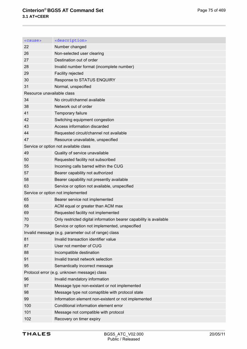
t BGS5_ATC_V02.000 20/05/11Public / Released
Cinterion® BGS5 AT Command Set 3.1 AT+CEER
Page 75 of 469
22 Number changed
26 Non-selected user clearing
27 Destination out of order
28 Invalid number format (incomplete number)
29 Facility rejected
30 Response to STATUS ENQUIRY
31 Normal, unspecified
Resource unavailable class
34 No circuit/channel available
38 Network out of order
41 Temporary failure
42 Switching equipment congestion
43 Access information discarded
44 Requested circuit/channel not available
47 Resource unavailable, unspecified
Service or option not available class
49 Quality of service unavailable
50 Requested facility not subscribed
55 Incoming calls barred within the CUG
57 Bearer capability not authorized
58 Bearer capability not presently available
63 Service or option not available, unspecified
Service or option not implemented
65 Bearer service not implemented
68 ACM equal or greater than ACM max
69 Requested facility not implemented
70 Only restricted digital information bearer capability is available
79 Service or option not implemented, unspecified
Invalid message (e.g. parameter out of range) class
81 Invalid transaction identifier value
87 User not member of CUG
88 Incompatible destination
91 Invalid transit network selection
95 Semantically incorrect message
Protocol error (e.g. unknown message) class
96 Invalid mandatory information
97 Message type non-existant or not implemented
98 Message type not comaptible with protocol state
99 Information element non-existent or not implemented
100 Conditional information element error
101 Message not compatible with protocol
102 Recovery on timer expiry
<cause> <description>

t BGS5_ATC_V02.000 20/05/11Public / Released
Cinterion® BGS5 AT Command Set 3.1 AT+CEER
Page 76 of 469
3.1.2 Internal failure causes
111 Protocol error, unspecified
Interworking class
127 Interworking, unspecified
212 APN resriction
<cause> <description>
0 No cause information available
256 Internal, unspecified
257 Out of memory
258 Invalid parameters
259 Data call active
260 Speech call active
262 Missing ACM information
263 Temporary forbidden
264 Called party is blacklisted
265 Blacklist is full
266 No service
267 Limited service
268 Client conflict
269 Dual service call active
271 Unknown SIM error
274 Active Client is Gone
277 SIM status failure
278 Rejected by call control
279 FDN failed control
280 BDN failed control
283 CCBS possible
284 Invalid alternate service line
285 LND overflow
287 MM network failure unspecified
288 MM no service
289 MM access class barred
290 MM RR no resource
291 MM ME busy
292 MM unspecified
301 MMI not registered
303 Rejected by user
304 Rejected due to time out
306 Disconnected due to SIM-Toolkit call setup
<cause> <description>
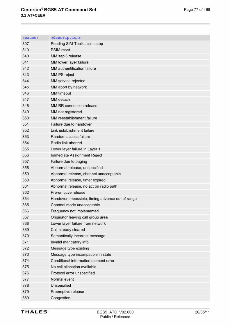
t BGS5_ATC_V02.000 20/05/11Public / Released
Cinterion® BGS5 AT Command Set 3.1 AT+CEER
Page 77 of 469
307 Pending SIM-Toolkit call setup
310 PSIM reset
340 MM sapi3 release
341 MM lower layer failure
342 MM authentification failure
343 MM PS reject
344 MM service rejected
345 MM abort by network
346 MM timeout
347 MM detach
348 MM RR connection release
349 MM not registered
350 MM reestablishment failure
351 Failure due to handover
352 Link establishment failure
353 Random access failure
354 Radio link aborted
355 Lower layer failure in Layer 1
356 Immediate Assignment Reject
357 Failure due to paging
358 Abnormal release, unspecified
359 Abnormal release, channel unacceptable
360 Abnormal release, timer expired
361 Abnormal release, no act on radio path
362 Pre-emptive release
364 Handover impossible, timing advance out of range
365 Channel mode unacceptable
366 Frequency not implemented
367 Originator leaving call group area
368 Lower layer failure from network
369 Call already cleared
370 Semantically incorrect message
371 Invalid mandatory info
372 Message type existing
373 Message type incompatible in state
374 Conditional information element error
375 No cell allocation available
376 Protocol error unspecified
377 Normal event
378 Unspecified
379 Preemptive release
380 Congestion
<cause> <description>

t BGS5_ATC_V02.000 20/05/11Public / Released
Cinterion® BGS5 AT Command Set 3.1 AT+CEER
Page 78 of 469
3.1.3 Release causes for packet switched features
381 RE establishment reject
382 Directed sig conn establishment
383 User inactivity
384 Lower layer failure downlink
385 Lower layer failure uplink
386 Cell barred due to authentication failure
387 signalling connection release
388 CS connection release triggered by MM
391 resource conflict
392 Layer 2 sequence error
393 Layer 2 T200 exp N200 plus 1 times
394 Layer 2 unsolicited DM resp MFES
395 Layer 2 contention resolution
396 Layer 2 normal cause
397 RR connection release due to BAND change (2G)
400 MM RR connection error while release
500 local user disconnect/normal call clearing
510 user or NW disconnect/normal call clearing,during any other call state than
511 Remote user/NW disconnected for call status is CALLPROCEEDING
512 Request rejected, BCM violation
<cause> <description>
103 Illegal MS
106 Illegal ME
107 GPRS service not allowed
112 Location area not allowed
113 Roaming not allowed in this location area
124 MBMS bearer capabilities insufficient for the service
125 LLC or SNDCP failure
126 Insufficient resources
128 Unknown PDP address or PDP type
129 User authentication failed
130 Activation rejected by GGSN
131 Activation reject,unspecified
132 Service not supported
133 Service not subscribed
134 Service temporarily out of order
135 NSAPI already used
136 Regular PDP context deactivation
<cause> <description>
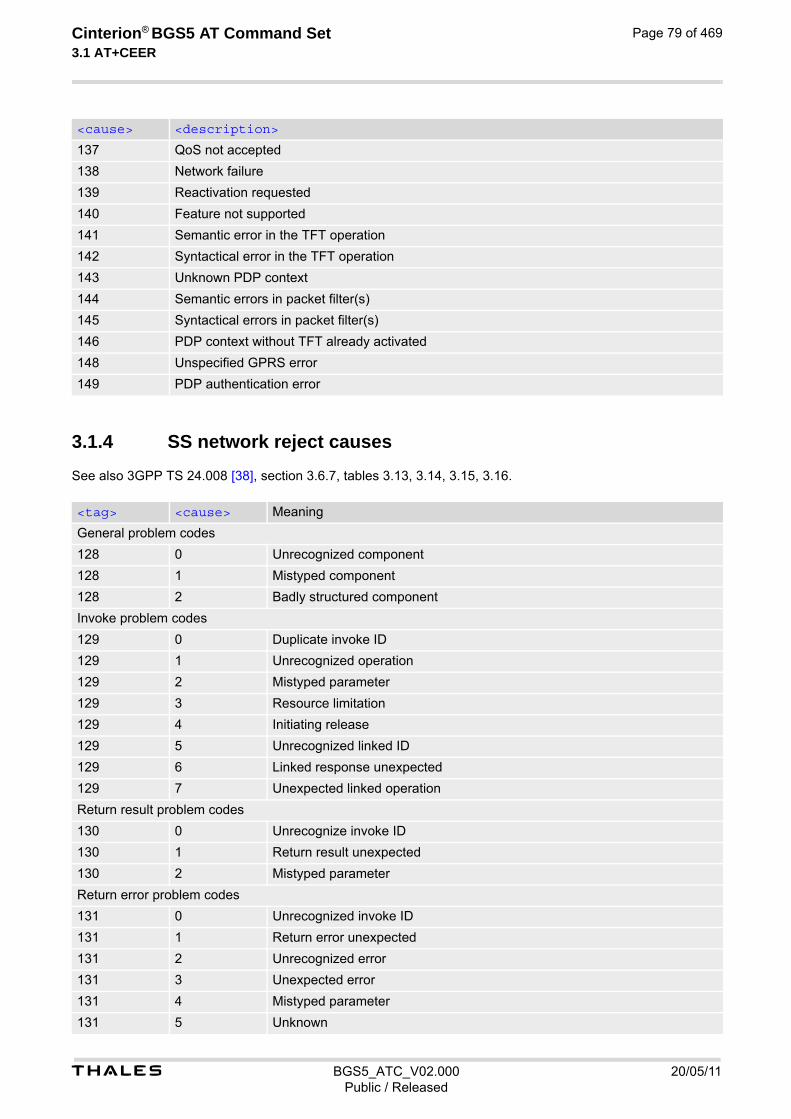
t BGS5_ATC_V02.000 20/05/11Public / Released
Cinterion® BGS5 AT Command Set 3.1 AT+CEER
Page 79 of 469
3.1.4 SS network reject causes
See also 3GPP TS 24.008 [38], section 3.6.7, tables 3.13, 3.14, 3.15, 3.16.
137 QoS not accepted
138 Network failure
139 Reactivation requested
140 Feature not supported
141 Semantic error in the TFT operation
142 Syntactical error in the TFT operation
143 Unknown PDP context
144 Semantic errors in packet filter(s)
145 Syntactical errors in packet filter(s)
146 PDP context without TFT already activated
148 Unspecified GPRS error
149 PDP authentication error
<tag> <cause> Meaning
General problem codes
128 0 Unrecognized component
128 1 Mistyped component
128 2 Badly structured component
Invoke problem codes
129 0 Duplicate invoke ID
129 1 Unrecognized operation
129 2 Mistyped parameter
129 3 Resource limitation
129 4 Initiating release
129 5 Unrecognized linked ID
129 6 Linked response unexpected
129 7 Unexpected linked operation
Return result problem codes
130 0 Unrecognize invoke ID
130 1 Return result unexpected
130 2 Mistyped parameter
Return error problem codes
131 0 Unrecognized invoke ID
131 1 Return error unexpected
131 2 Unrecognized error
131 3 Unexpected error
131 4 Mistyped parameter
131 5 Unknown
<cause> <description>

t BGS5_ATC_V02.000 20/05/11Public / Released
Cinterion® BGS5 AT Command Set 3.1 AT+CEER
Page 80 of 469
3.1.5 SS network error causes
See also 3GPP TS 24.008 [38], section 4.5 except internal error 0 and 255.
<cause> Meaning
0 MS_INT_SS_ERROR
1 Unknown subscriber
9 Illegal subscriber
10 Bearer service not provisioned
11 Teleservice not provisioned
12 Illegal equipment
13 Call barred
16 Illegal SS operation
17 SS error status
18 SS not available
19 SS subscription violation
20 SS incompatibility
21 Facility not supported
27 Absent subscriber
29 Short term denial
30 Long term denial
34 System failure
35 Data missing
36 Unexpected data value
37 PW registration failure
38 Negative PW check
43 Number of PW attempts violation
54 POS method failure
71 Unknown alphabet
72 USSD busy
121 Rejected by user
122 Rejected by network
123 Deflection to server subscribed
124 Special service code
125 Invalid deflected number
126 Max number of MPTY participants exceeded
127 Resources not available
255 MS_INT_SS_TIME_OUT

t BGS5_ATC_V02.000 20/05/11Public / Released
Cinterion® BGS5 AT Command Set 3.2 AT^SIND
Page 81 of 469
3.2 AT^SIND Extended Indicator Control
AT^SIND controls the presentation of indicator event URCs. You can enable or disable URCs to be issued by the BGS5 each time the value of the related indicator changes, you can request the current status of all indica-tors, and you can also query the status of a single indicator.
SyntaxTest Command
AT^SIND=?Response(s)
^SIND: (<indDescr>, list of supported <indValue>s)[, (<indDescr>, list of supported <indValue>s)[, ...]], (list of supported <mode>s)OK
Read Command
AT^SIND?Response(s)
^SIND: <indDescr>, <mode>[, <indValue>][^SIND: <indDescr>, <mode>[, <indValue>]]...
In case of <indDescr>="eons"^SIND: eons, <mode>, <indValue>, <eonsOperator>, <servProvider>
In case of <indDescr>="nitz"^SIND: nitz, <mode>, <nitzUT>, <nitzTZ>, <nitzDST>
In case of <indDescr>="lsta"^SIND: lsta, <mode>, <lstaLevel>OKERROR+CME ERROR: <err>
Write Command
AT^SIND=<indDescr>, <mode>Response(s)
^SIND: <indDescr>, <mode>[, <indValue>]
In case of: <indDescr>="eons" and <mode>=2^SIND: <indDescr>, <mode>, <indValue>, <eonsOperator>, <servProvider>
In case of: <indDescr>="nitz" and <mode>=2^SIND: <indDescr>, <mode>, <nitzUT>, <nitzTZ>, <nitzDST>OKERROR+CME ERROR: <err>
Write Command
AT^SIND="lsta", <mode>[, <lstaLevel>]Response(s)
^SIND: lsta, <mode>, <lstaLevel>OKERROR+CME ERROR: <err>

t BGS5_ATC_V02.000 20/05/11Public / Released
Cinterion® BGS5 AT Command Set 3.2 AT^SIND
Page 82 of 469
Unsolicited Result Codes
URC 1
Format of the standard indicator:
+CIEV: <indDescr>, <indValue>
Value of an indicator has changed.
URC 2
Format of the "simdata" indicator:
+CIEV: <indDescr>
This URC is issued indicating that the content of one or more SIM Elementary Files has been changed.
URC 3
Format of the "eons" indicator:
+CIEV: <indDescr>, <indValue>, <eonsOperator>, <servProvider>
One URC is issued for each new LAI (Location Area Information) broadcast by the network.
URC 4
Format of the "nitz" indicator:
+CIEV: <indDescr>, <nitzUT>, <nitzTZ>, <nitzDST>
URC 5
Format of the "lsta" indicator: In case <indValue> equals "0".
+CIEV: <indDescr>, <indValue>, <lstaEdv>, <lstaRssi>
The URC is issued for every radio link error. It provides the error downcounter value corresponding to number of consecutive errors on downlink and the RSSI of the serving cell. Error downcounter value of <lstaLevel>-1 corresponds to first error occurred on downlink, 0 corresponds to last before cell loss.
URC 6
In case <indValue> equals "1".
+CIEV: <indDescr>, <indValue>, <lstaNo>, <lstaMin>, <lstaMax>, <lstaMean>, <lstaVar>
After the error downcounter reaches the value 0 the URC provides some statistic parameters of signal strength distribution across the band. Weighing the probability of finding an appropriate cell during a complete network scan and a possible high power consumption, the module will not search the complete frequency range with every scan, but will instead alternately scan only cells that were recorded to have a good signal strength at the time of network registra-tion. This algorithm is reflected in the below sample URCs: +CIEV:"lsta",1,40,63,63,63,0 (scan of complete frequency range) +CIEV:"lsta",1,1,63,63,63,0 (scan of previously recorded frequencies) +CIEV:"lsta",1,0,0,0,0,0 (scan of previously recorded frequencies) +CIEV:"lsta",1,40,63,63,63,0(scan of complete frequency range)
PIN Last
- + -
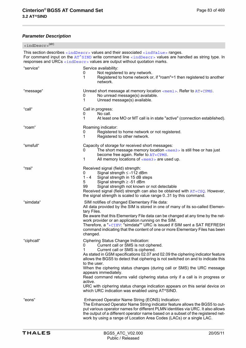
t BGS5_ATC_V02.000 20/05/11Public / Released
Cinterion® BGS5 AT Command Set 3.2 AT^SIND
Page 83 of 469
Parameter Description
This section describes <indDescr> values and their associated <indValue> ranges. For command input on the AT^SIND write command line <indDescr> values are handled as string type. In responses and URCs <indDescr> values are output without quotation marks.
“service“ Service availability:
“message“ Unread short message at memory location <mem1>. Refer to AT+CPMS.
“call“ Call in progress:
“roam“ Roaming indicator:
“smsfull“ Capacity of storage for received short messages:
“rssi“ Received signal (field) strength:
Received signal (field) strength can also be obtained with AT+CSQ. However, the signal strength is scaled to value range 0..31 by this command.
“simdata“ SIM notifies of changed Elementary File data: All data provided by the SIM is stored in one of many of its so-called Elemen-tary Files. Be aware that this Elementary File data can be changed at any time by the net-work provider or an application running on the SIM. Therefore, a "+CIEV: "simdata"" URC is issued if SIM sent a SAT REFRESH command indicating that the content of one or more Elementary Files has been changed.
“ciphcall“ Ciphering Status Change Indication:
As stated in GSM specifications 02.07 and 02.09 the ciphering indicator feature allows the BGS5 to detect that ciphering is not switched on and to indicate this to the user. When the ciphering status changes (during call or SMS) the URC message appears immediately. Read command returns valid ciphering status only if a call is in progress or active. URC with ciphering status change indication appears on this serial device on which URC indication was enabled using AT^SIND.
“eons“ Enhanced Operator Name String (EONS) Indication: The Enhanced Operator Name String indicator feature allows the BGS5 to out-put various operator names for different PLMN identities via URC. It also allows the output of a different operator name based on a subset of the registered net-work by using a range of Location Area Codes (LACs) or a single LAC.
<indDescr>(str)
0 Not registered to any network.1 Registered to home network or, if "roam"=1 then registered to another
network.
0 No unread message(s) available.1 Unread message(s) available.
0 No call.1 At least one MO or MT call is in state "active" (connection established).
0 Registered to home network or not registered.1 Registered to other network.
0 The short message memory location <mem3> is still free or has just become free again. Refer to AT+CPMS.
1 All memory locations of <mem3> are used up.
0 Signal strength ≤ -112 dBm1 - 4 Signal strength in 15 dB steps5 Signal strength ≥ -51 dBm99 Signal strength not known or not detectable
0 Current call or SMS is not ciphered.1 Current call or SMS is ciphered.

t BGS5_ATC_V02.000 20/05/11Public / Released
Cinterion® BGS5 AT Command Set 3.2 AT^SIND
Page 84 of 469
The presentation of the "eons" indicator is determined by network activity. For example, the indicator appears every time a location update occurs or a NITZ information is sent, no matter whether or not the status of the EONS informa-tion has changed. This means that the same EONS information may be reported several times. The EONS tables are stored in the SIM and will be read at power-up. Following are the SIM Elementary Files that are affected by the introduction of EONS feature in the SIM: EFSST (SIM Service Table) - describes which features are active. If the Operator Name Source is CPHS Operator Name String long and short form, refer to <indValue>, the following two SIM Elementary Files will be used: EFONString (Operator Name String) - contains the name of the PLMN operator who issued the SIM. EFOPShort (Operator Name Short form) - contains a short form of the name of the PLMN operator who issued the SIM.
“nitz“ Network Identity and Time Zone indication: This indicator shows the time relevant information elements of an MM Informa-tion (MMI) or GMM Information (GMMI) message received from the network (see 3GPP TS 24.008 [38], ch. 9.2.15a and 9.4.19). The network usually sends a NITZ indicator when the mobile attaches to the network, when it enters a location area with different time zone or when a daylight change occurs. A NITZ indicator may consist of the following parameters: Universal Time (UT), local Time Zone (TZ), Daylight Saving Time (DST). All information elements of MMI/GMMI are optional and therefore, the presentation of the parameters <nitzUT>, <nitzTZ>, <nitzDST> varies with the network. For example, the network may send all three parameters UT, TZ, DST, or only UT and TZ or only TZ. UT is indicated in usual date/time format and represents the current world time (GMT) at the moment when sent. TZ is given as a positive (east) or negative (west) offset from UT in units of 15 minutes. DST shows the number of hours added to the local TZ because of daylight sav-ing time (summertime) adjustment. Usually DST is 1 hour but it can be also 2 hours in certain locations. Example for time and time zone with DST: +CIEV: nitz,"04/07/23,13:39:20",-28,1 In this example TZ is -28, showing a time offset of -7 hours (west) to Universal Time/GMT (which never changes for DST). DST is 1 which indicates that one hour was added to TZ because of Daylight Saving Time. If a network does not send the DST parameter the TZ value would be -32 (8 hours west) as would be done in winter: +CIEV: nitz,"04/11/23,13:39:20",-32 Please be aware that although the last NITZ value can be looked up again via "AT^SIND=nitz,2" the returned values may be out of date. Especially the UT value is obsolete because there is no internal NITZ clock and therefore no con-tinuation of UT. NITZ values are lost when the ME detaches from network. Also when a manual network selection fails and the ME automatically falls back to the previous net-work the NITZ values cannot be recalled. Nevertheless an indicated time zone is valid until a new MMI/GMMI will trigger another NITZ indication.
“psinfo“ Packet Switched Status Indication "psinfo" indicates the status of the ME related to packet switched data calls. 0 GPRS not available in currently used cell 1 GPRS available in currently used cell 2 GPRS attached

t BGS5_ATC_V02.000 20/05/11Public / Released
Cinterion® BGS5 AT Command Set 3.2 AT^SIND
Page 85 of 469
“lsta“ Link Stability Indication (for 2G only!) The Link Stability indicator feature allows the BGS5 to output radio link errors and statistic parameters of signal strength distribution across the band via URC.
The presentation of the "lsta" indicator is determined by the radio link spectrum shape. For example, each time a radio link error appears the URC indicates an Error Downcounter value and the RSSI of the serving cell to provide some kind of warning. Every consecutive error decrements the Error Downcounter value and successful downlink signal reception increments it again. The factor on which Error Downcounter is decremented depends on network settings. Error Downcounter value 0 means that the ME has lost the cell and will start the cell reselection process. In this case the URC is enhanced and includes the following statistic parameters of signal strength distribution across the band. These are: - Number of reported channels, - Maximal signal strength value, - Minimal signal strength value, - Mean value of signal strength across frequency band and - Variance of signal strength across frequency band. To avoid that radio link error URCs are output too often, when radio conditions are bad, you can select a lower warning level with <lstaLevel>.
“pacsp“ PLMN Mode Bit status Indication: "pacsp" indicates the parsed PLMN Mode Bit value of the SIM Elementary File EFCSP (Customer Service Profile) according to Common PCN Handset Speci-fication (CPHS) [46].
The contents of the SIM Elementary File EFCSP may be changed by the net-work in the background at any time via SIM Application Toolkit (SAT) proce-dure "Data download to SIM". For a detailed description please refer to 3GPP TS 11.14 [19], 3GPP TS 31.111 [20], ETSI TS 102 223 [21]. Please note, that URC presentation <mode> for this indicator is stored non-vol-atile.
“simtray“ Indication of SIM tray status as indicated by CCIN line. Result does not depend on whether the tray holds a SIM or not. Generating a URC on status change is not supported.
Integer type value in the range stated above for the corresponding <indDescr>. Notes specific to the EONS feature: If the indicator is "eons", the <indValue> is a type associated to the operator name according to 3GPP TS 22.101 [45]. This type depends on the source of the operator name. Priority of types associated to the operator names is defined as follows (the type listed first has the highest pri-ority). If a type cannot be indicated the next one will be used.
0 Radio link error.1 Radio link signal strength distribution.
0 CSP PLMN mode bit off1 CSP PLMN mode bit on99 CSP PLMN mode bit not defined or SIM Elementary File EFCSP not
accessible
0 SIM tray empty.1 SIM tray plugged in.
<indValue>(num)
0 Not registered.1 EFOPL and EFPNN (alphanumeric format, can contain up to 24 characters.)2 Operator Name String in long and short format according to Common PCN
Handset Specification (CPHS) [46] (alphanumeric format, can contain up to 16 characters).

t BGS5_ATC_V02.000 20/05/11Public / Released
Cinterion® BGS5 AT Command Set 3.2 AT^SIND
Page 86 of 469
If the type is 2, 4 or 5, AT+COPS with the appropriate <mode> displays the same operator name.
Set or query URC presentation mode of a specific indicator <indDescr>.
0(P) Disables the presentation of a specific URC.
1 Enables the presentation of a specific URC.
2 Requests the presentation mode of the URC status and the current value of a single indicator type.
Operator in format which depends on the type associated to the operator name. Refer to <indValue>.
Service Provider Name according to the status settings (SIM Service No. 17) in the SIM Service Table (SST) of the SIM. Service Provider Name (SPN) will be read from EFSPN.
Universal Time delivered as part of the "nitz" Indicator. Refer to <indDescr>.
Time Zone delivered as part of the "nitz" Indicator. Refer to <indDescr>.
Adjustment for Daylight Saving Time as part of the "nitz" Indicator. Refer to <indDescr>.
Warning Level
0-10 User value to limit the indication of radio link errors.
Refer to <indDescr>.
EDV (0-10) Error Downcounter value scaled. Refer to <indDescr>.
(value-110) dBm Received signal strength indication value. Refer to <indDescr>.
Number of reported channels. Refer to <indDescr>.
3 Name information received by the NITZ service long and short form (alphanu-meric format, can contain up to 16 characters). The short form will be displayed only if EFOPShort from CPHS is available.
4 Any operator name stored internal to the ME (alphanumeric format, can con-tain up to 16 characters).
5 Broadcast MCC-MNC (numeric format which consists of a 3-digit country code plus a 2- or 3-digit network code).
<mode>(num)
<eonsOperator>(str)(+CSCS)
<servProvider>(str)(+CSCS)
<nitzUT>(str)(+CSCS)
<nitzTZ>(num)
<nitzDST>(num)
<lstaLevel>(num)
<lstaEdv>(num)
<lstaRssi>(num)
<lstaNo>(num)
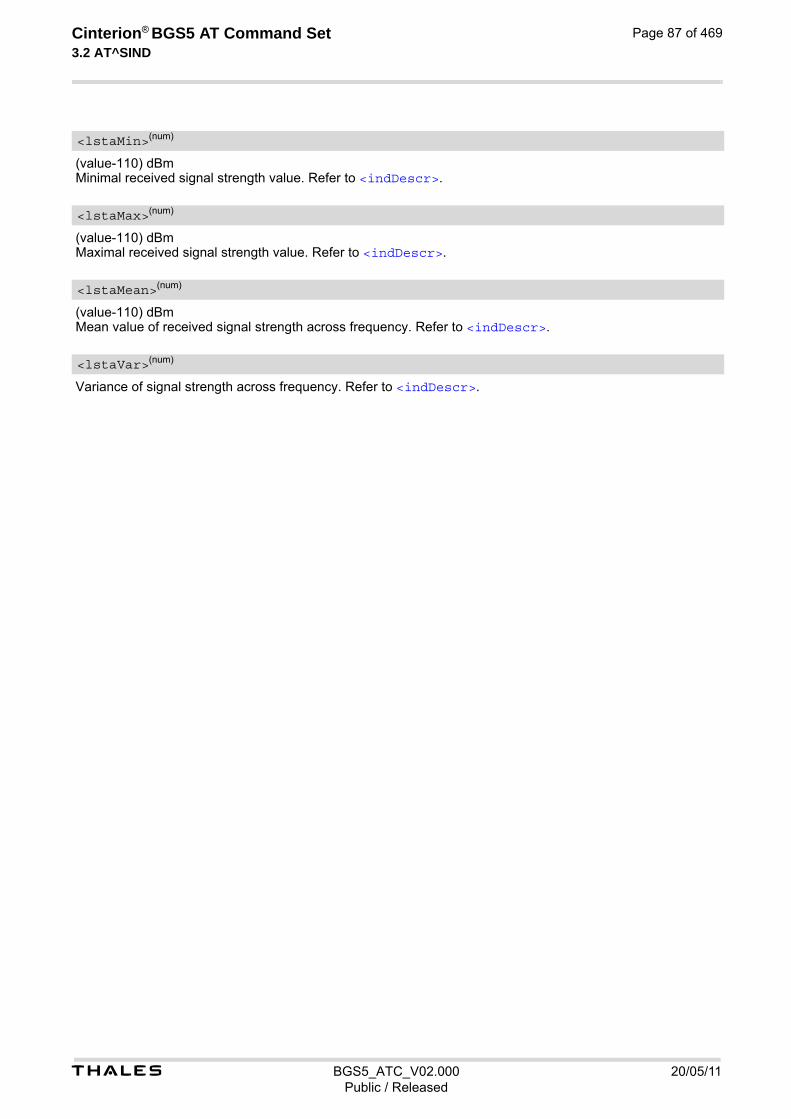
t BGS5_ATC_V02.000 20/05/11Public / Released
Cinterion® BGS5 AT Command Set 3.2 AT^SIND
Page 87 of 469
(value-110) dBm Minimal received signal strength value. Refer to <indDescr>.
(value-110) dBm Maximal received signal strength value. Refer to <indDescr>.
(value-110) dBm Mean value of received signal strength across frequency. Refer to <indDescr>.
Variance of signal strength across frequency. Refer to <indDescr>.
<lstaMin>(num)
<lstaMax>(num)
<lstaMean>(num)
<lstaVar>(num)

t BGS5_ATC_V02.000 20/05/11Public / Released
Cinterion® BGS5 AT Command Set 3.3 AT+CPAS
Page 88 of 469
3.3 AT+CPAS Activity Status
AT+CPAS execute command queries BGS5's activity status.
Syntax
Parameter Description
0 Ready (ME allows commands from TE)
1 Unavailable (ME does not allow commands from TE)
2 Unknown(ME is not guaranteed to respond to instructions)
3 Ringing (ME is ready for commands from TE, but the ringer is active)
4 Call in progress, held, waiting (ME is ready for commands from TE)
5 Asleep (ME is unable to process commands from TE because it is in a low functionality state)
Test Command
AT+CPAS=?Response(s)
+CPAS: (list of supported<pas>s)OK
Exec Command
AT+CPASResponse(s)
+CPAS: <pas>OK
PIN Last Reference(s)
- + - 3GPP TS 27.007 [43]
<pas>(num)

Cinterion® BGS5 AT Command Set 4. Serial Interface Control Commands
t BGS5_ATC_V02.000 20/05/11Public / Released
Page 89 of 469
4. Serial Interface Control Commands
The AT Commands described in this chapter allow the external application to determine various settings related to the BGS5's serial interface.
4.1 AT\Q Flow Control
AT\Q allows to configure flow control on the asynchronous serial interfaces ASC0 and ASC1 (UARTs). It is strongly recommended to always use RTS/CTS hardware flow control. In particular, when using SLEEP mode (see AT^SPOW) or Multiplex mode (see AT+CMUX), ensure that both ME and TE have RTS/CTS hardware flow control enabled. The AT\Q setting is always common for all interfaces and can be changed, for compatibility reasons, on each interface, but is only applicable to the ASC0 and ASC1 interfaces. AT\Q settings have no effect on the USB ports because the USB protocol integrates a flow control mechanism of its own.
Syntax
Parameter Description
[0] Disable flow control
1 XON/XOFF software flow control Value 1 can be set on ASC0 and ASC1, but XON/XOFF software flow control takes effect only on ASC0. On ASC1, RTS/CTS hardware flow control remains effective even though value 1 has been selected.
2 This value is not supported and will be mapped to RTS/CTS hardware flow control
3(&F)(D) RTS/CTS hardware flow control Note• When using XON/XOFF flow control (AT\Q1) in online mode, +++ should not be used while the data trans-
mission is paused with XOFF. Before entering the command mode with +++ the paused transmission should be resumed using the XON character.
Exec Command
AT\Q[<n>]Response(s)
OK
PIN Last
- + -
<n>(num)(&V)(&W)

t BGS5_ATC_V02.000 20/05/11Public / Released
Cinterion® BGS5 AT Command Set 4.2 AT&C
Page 90 of 469
4.2 AT&C Set Data Carrier Detect (DCD) Line Mode
The AT&C command controls the behavior of the ME's DCD line. AT&C offers full functionality only if the DCD0 line is enabled with AT^SCFG="GPIO/mode/DCD0","std". Other-wise AT&C will respond "+CME ERROR: operation not allowed".
Syntax
Parameter Description
[0] DCD line shall always be on.
1(&F) DCD line shall be on only when data carrier signal is present.
2 DCD line shall be on when one or more Internet services defined on the related serial channel are in an active state as described below. For details on the var-ious service states refer to AT^SISI, parameter <srvState> or AT^SISO, parameter <srvState>. The DCD line status for an Internet service is sig-naled at the interface where the service had been opened with the AT com-mand AT^SISO.
• Transparent TCP or Transparent UDP client, SOCKET, HTTP, SMTP: DCD shall be on when <srvState>="Connnecting" or "Up"
• Transparent TCP Listener: DCD shall be on when <srvState>="Up", "Alerting", "Connected" and "Released"
• FTP: DCD shall be on when data channel is connected, i.e. <srvState>="Up"
Exec Command
AT&C[<value>]Response(s)
OK
PIN Last Reference(s)
- + - V.250
<value>(num)(&V)(&W)

t BGS5_ATC_V02.000 20/05/11Public / Released
Cinterion® BGS5 AT Command Set 4.3 AT&D
Page 91 of 469
4.3 AT&D Set Data Terminal Ready (DTR) Line Mode
AT&D determines how the ME responds if the DTR line is changed from ON to OFF state during data connection ( CSD or PPP or active Internet Services transparent access mode; refer to AT^SIST). AT&D offers full functionality only if the DTR0 line is enabled with AT^SCFG="GPIO/mode/DTR0","std". Otherwise AT&D will respond "+CME ERROR: operation not allowed".
Syntax
Parameter Description
[0] ME ignores status of the DTR line.
1 ON->OFF on DTR: Change to command mode while retaining the data con-nection.
2(&F) ON->OFF on DTR: Disconnect the data connection (only for CSD and PPP ) and change to command mode. For Internet service the behaviour is like AT&D1. During OFF state of the DTR line the auto-answer function (see ATS0) is disabled.
Exec Command
AT&D[<value>]Response(s)
OK
PIN Last Reference(s)
- + - V.250
<value>(num)(&V)(&W)

t BGS5_ATC_V02.000 20/05/11Public / Released
Cinterion® BGS5 AT Command Set 4.4 AT&S
Page 92 of 469
4.4 AT&S Set Data Set Ready (DSR) Line Mode
AT&S determines how the ME sets the DSR line depending on its communication state. AT&S offers full functionality only if the DSR0 line is enabled with AT^SCFG="GPIO/mode/DSR0","std". Other-wise AT&S will respond "+CME ERROR: operation not allowed".
Syntax
Parameter Description
[0](&F) DSR line is always ON
1 ME in command mode: DSR is OFF. ME in data mode: DSR is ON.
Exec Command
AT&S[<value>]Response(s)
OK
PIN Last Reference(s)
- + - ITU-T V.250 [15]
<value>(num)(&V)(&W)

t BGS5_ATC_V02.000 20/05/11Public / Released
Cinterion® BGS5 AT Command Set 4.5 ATE
Page 93 of 469
4.5 ATE AT Command Echo
ATE controls if the BGS5 echoes characters received from TE during AT command state.
Syntax
Parameter Description
[0] Echo mode off
1(&F) Echo mode on
Exec Command
ATE[<value>]Response(s)
OK
PIN Last Reference(s)
- + - V.250
<value>(num)(&V)(&W)

t BGS5_ATC_V02.000 20/05/11Public / Released
Cinterion® BGS5 AT Command Set 4.6 AT+IPR
Page 94 of 469
4.6 AT+IPR Bit Rate
AT+IPR allows to query and set the bit rate of the BGS5's asynchronous serial interface (UART). The test command returns the values of supported automatically detectable bit rates and the values of the sup-ported fixed bit rates. The read command returns the bit rate currently used on the interface. The write command specifies the bit rate to be used for the interface. If using a fixed bit rate, make sure that both BGS5 and TE are configured to the same rate. In case of Autobaud mode (AT+IPR=0) the detected TE bit rate will not be saved and, therefore, needs to be resynchronized after any restart of the ME (for details refer to Section 4.6.1, Autobauding). It is not recommended to set bit rates lower than 9600 bps in order to avoid timing problems (see Section 1.6, Communication between Customer Application and BGS5 for details about timing).
Syntax
Parameter Description
Bit rate per second (bps)
0 Autobauding See Section 4.6.1, Autobauding for further details.
1200
2400
4800
9600
19200
38400
57600
115200(D)
Test Command
AT+IPR=?Response(s)
+IPR: (list of supported auto-detectable <rate>s), (list of supported fixed-only <rate>s)OK
Read Command
AT+IPR?Response(s)
+IPR: <rate>OK
Write Command
AT+IPR=<rate>Response(s)
OKERROR+CME ERROR: <err>
PIN Last
- + +
<rate>(num)(&V)(NV)

t BGS5_ATC_V02.000 20/05/11Public / Released
Cinterion® BGS5 AT Command Set 4.6 AT+IPR
Page 95 of 469
230400
460800
500000
750000
921600 Note• Generally, AT+IPR should be used as a standalone command as specified in Section 1.5.2, Concatenating
AT Commands. If nevertheless combinations with other commands on the same command line cannot be avoided, there are several constraints to be considered:
- Avoid combinations with the AT commands listed in Section 1.5.2, Concatenating AT Commands.
- Keep in mind that there shall be a minimum pause between two AT commands as specified in Section 1.6, Communication between Customer Application and BGS5.
- If switching to the new bit rate takes effect while a response is being transmitted, the last bytes may be sent with the new bit rate and thus, not properly transmitted. The following commands will be correctly sent at the new bit rate. Please consider this effect especially when local echo is active (ATE1).
4.6.1 Autobauding
To take advantage of Autobaud mode specific attention must be paid to the following requirements:
• If Autobaud mode is set, ensure that the ME detects the bit rate set in the TE. To do so, enter an "AT" or "at" string each time after restarting the ME. (Note that other strings, such as "a", "At" or "aT" will not be detected.) After detecting the bit rate the ME will send the "^SYSSTART" URC. Other URCs that may have been buffered before the bit rate was detected will be printed after the "^SYS-START" URC. For example, if SIM PIN1 password request is disabled (AT+CLCK="SC",0,"xxxx") the "+PBREADY" URC may follow after the "^SYSSTART" URC.
• After the successful synchronization between TE and ME the Autobaud mode mechanism of the ME is deac-tivated until next restart. So, while Autobaud mode is set you will need to restart the ME each time after chang-ing the bit rate of the TE.
• There is no need to set Autobauding manually on USB port, the implementation method is different with Uart port.

t BGS5_ATC_V02.000 20/05/11Public / Released
Cinterion® BGS5 AT Command Set 4.7 AT+CMUX
Page 96 of 469
4.7 AT+CMUX Multiplex mode
Multiplex mode according to 3GPP TS 27.010 [5] enables the use of virtual channels set up over one single serial interface. Every channel is used as an independent serial link. This way, up to three simultaneous AT command sessions can be handled at a time. For example, the first Mux channel can be used to send or receive data, while two Mux channels are available to control the module with AT commands or to establish a dedicated channel to receive Unsolicited Result Codes (URC), e.g. "+CIEV:" or "RING". The multiplex driver can be installed on the first serial interface ASC0 and all USB AT command instances.. At a time Multiplex mode it can be started only on one of these interfaces. All remaining AT instances can be used in parallel. The second serial interface ASC1 is not recommended to be used for Multiplex mode. BGS5 incorporates an internal multiplexer and thus integrates all the functions needed to implement full-featured multiplex solutions. For the application on top, customers have the flexibility to create their own multiplex pro-grams conforming to the multiplexer protocol. To help system integrators save the time and expense of designing multiplexer applications, THALES DIS AIS Deutschland GmbH offers WinMUX, a ready-to-use multiplex driver for Windows XP, Windows Vista, Windows 7 and higher, available as 32 and 64 bit version. Another approach is to develop customized solutions based on the sources of the WinMUX driver. Refer to "Multiplexer User's Guide" [4] which provides a detailed description of the multiplex architecture and step-by-step instructions of how to install and configure the Multiplex mode. The WinMUX driver and its source files can be supplied on request. Please contact your local distributor to obtain the latest installation software and user's guide. AT+CMUX write command is used to enter Multiplex mode. Setup of the logical channels is initiated by the TE, i.e. the TE acts as initiator. This means that the TE shall ensure that logical channels are established before any further actions on the channels can be started. There is a timeout of five seconds, if the multiplexer protocol is enabled but no multiplexer control channel is established. Afterwards BGS5 returns to AT command mode. The parameter maximum frame size (N1) according to 3GPP TS 27.010 [5] is implemented as 98 bytes by default. All other parameters are not available. Refer to "Multiplexer User's Guide" [4] for further details regarding frame size.
Syntax
Test Command
AT+CMUX=?Response(s)
+CMUX: (list of supported<mode>s)OK
Read Command
AT+CMUX?Response(s)
+CMUX: <mode>OKERROR+CME ERROR: <err>
Write Command
AT+CMUX=<mode>Response(s)
OKERROR+CME ERROR: <err>
PIN Last Reference(s)
- + + 3GPP TS 27.007 [43], 3GPP TS 27.010 [5]

t BGS5_ATC_V02.000 20/05/11Public / Released
Cinterion® BGS5 AT Command Set 4.7 AT+CMUX
Page 97 of 469
Parameter Description
Enable Multiplex mode.
0 Basic option Notes• In Multiplex mode, the write command AT+IPR=<rate> is accepted and always returns "OK" but has no
effect.
• Please note that it is recommended to stop the multiplexer protocol only when all channels are in idle state.
<mode>(num)

t BGS5_ATC_V02.000 20/05/11Public / Released
Cinterion® BGS5 AT Command Set 4.8 AT+ICF
Page 98 of 469
4.8 AT+ICF Character Framing
AT+ICF controls character framing and parity format used for receiving and transmitting data via BGS5's asyn-chronous serial interfaces (UART). Following settings are supported:
• 7 bits, even parity, 1 stop bit (AT+ICF=5,1)
• 7 bits, odd parity, 1 stop bit (AT+ICF=5,0)
• 8 bits, even parity, 1 stop bit (AT+ICF=2,1)
• 8 bits, no parity, 1 stop bit (AT+ICF=3)
• 8 bits, odd parity, 1 stop bit (AT+ICF=2,0)
• 8 bits, no parity, 2 stop bits (AT+ICF=1)
The selected setting is stored in the user defined profile with next AT&W. It will only be used on next start of the BGS5 if configured to use a fixed bit rate, i.e. without autobaud usage. The autobaud feature (refer AT+IPR) detects bit rate and character framing currently used by a connected TE. However, this detection suffers some limitations described at Section 4.6.1, Autobauding. AT+ICF read command will always show the setting stored in the user defined profile, not a currently detected character framing. If Autobauding is enabled (AT+IPR=0), changing AT+ICF settings is not allowed. If the current <format> setting uses no parity (e.g. <format>=3) and AT+ICF is used to switch to a format with parity (e.g. <format>=2), it is necessary to explicitly set parameter <parity>, e.g. AT+ICF=2,1. If not done correctly BGS5 will respond with "+CME ERROR: invalid index". This is because for <format>=3, the parameter <parity> is set to the internal value 'no parity' which is not supported by <format>=2. Please remember that if an optional parameter is omitted for which no default is stated in this document, the value of the parameter remains unchanged.
Syntax
Test Command
AT+ICF=?Response(s)
+ICF: (list of supported <format>s), (list of supported <parity>s)OK
Read Command
AT+ICF?Response(s)
+ICF: <format>[, <parity>]OK
Write Command
AT+ICF=[<format>[, <parity>]]Response(s)
OKERROR+CME ERROR: <err>
PIN Last Reference(s)
- + + V.250
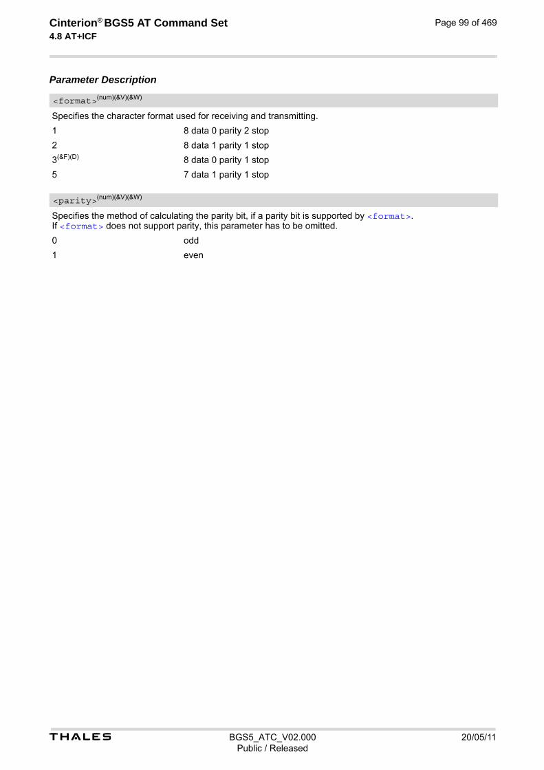
t BGS5_ATC_V02.000 20/05/11Public / Released
Cinterion® BGS5 AT Command Set 4.8 AT+ICF
Page 99 of 469
Parameter Description
Specifies the character format used for receiving and transmitting.
1 8 data 0 parity 2 stop
2 8 data 1 parity 1 stop
3(&F)(D) 8 data 0 parity 1 stop
5 7 data 1 parity 1 stop
Specifies the method of calculating the parity bit, if a parity bit is supported by <format>. If <format> does not support parity, this parameter has to be omitted.
0 odd
1 even
<format>(num)(&V)(&W)
<parity>(num)(&V)(&W)

Cinterion® BGS5 AT Command Set 5. Identification Commands
t BGS5_ATC_V02.000 20/05/11Public / Released
Page 100 of 469
5. Identification Commands
The AT Commands described in this chapter allow the external application to obtain various identification infor-mation related to the BGS5 and linked entities.
5.1 ATI Display product identification information
The ATI execute command delivers a product information text.
Syntax
Notes• The "Revision" information consists of the following parts: Version xx and variant yyy of software release.
• "A-REVISION aa.bbb.cc" information consists of the following parts: Application Revision Number 'aa' as an indication of the supported application ('01' ... no dedicated applica-tion is present, ATC is the default application). Default value is "00". Application Revision Version 'bbb' as an assignment to changes in customer application. Default value is "000". 'cc' as an additional number, e.g. defined by customer. Default value is "00".
Exec Command
ATIResponse(s)
CinterionBGS5REVISION xx.yyyOK
Exec Command
ATI1Response(s)
CinterionBGS5REVISION xx.yyyA-REVISION aa.bbb.ccOK
PIN Last Reference(s)
- + - ITU-T V.250 [15]

t BGS5_ATC_V02.000 20/05/11Public / Released
Cinterion® BGS5 AT Command Set 5.2 AT+CGMI
Page 101 of 469
5.2 AT+CGMI Request manufacturer identification
AT+CGMI returns a manufacturer identification text.
SyntaxTest Command
AT+CGMI=?Response(s)
OK
Exec Command
AT+CGMIResponse(s)
CinterionOK
PIN Last Reference(s)
- + - 3GPP TS 27.007 [43]

t BGS5_ATC_V02.000 20/05/11Public / Released
Cinterion® BGS5 AT Command Set 5.3 AT+CGMM
Page 102 of 469
5.3 AT+CGMM Request model identification
AT+CGMM returns a product model identification text.
SyntaxTest Command
AT+CGMM=?Response(s)
OK
Exec Command
AT+CGMMResponse(s)
BGS5OK
PIN Last Reference(s)
- + - 3GPP TS 27.007 [43]
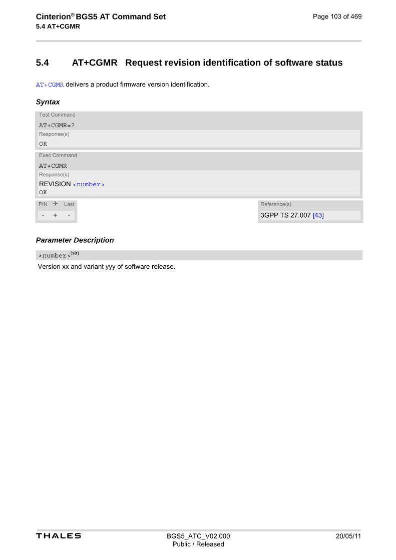
t BGS5_ATC_V02.000 20/05/11Public / Released
Cinterion® BGS5 AT Command Set 5.4 AT+CGMR
Page 103 of 469
5.4 AT+CGMR Request revision identification of software status
AT+CGMR delivers a product firmware version identification.
Syntax
Parameter Description
Version xx and variant yyy of software release.
Test Command
AT+CGMR=?Response(s)
OK
Exec Command
AT+CGMRResponse(s)
REVISION <number>OK
PIN Last Reference(s)
- + - 3GPP TS 27.007 [43]
<number>(str)

t BGS5_ATC_V02.000 20/05/11Public / Released
Cinterion® BGS5 AT Command Set 5.5 AT+CGSN
Page 104 of 469
5.5 AT+CGSN Request International Mobile Equipment Identity (IMEI)
AT+CGSN delivers the International Mobile Equipment Identity (IMEI). Command is identical with: AT+GSN.
Syntax
Parameter Description
International Mobile Equipment Identity (IMEI) identifying a mobile equipment used in the mobile network. IMEI is composed of Type Allocation Code (TAC) (8 digits), Serial Number (SNR) (6 digits) and the Check Digit (CD) (1 digit). For information on IMEI refer to 3GPP TS 23.003, subclause 6.2.1 and 3GPP TS 27.007 [43].
Test Command
AT+CGSN=?Response(s)
OK
Exec Command
AT+CGSNResponse(s)
<sn>OK
PIN Last Reference(s)
- + - 3GPP TS 27.007 [43]
<sn>(str)
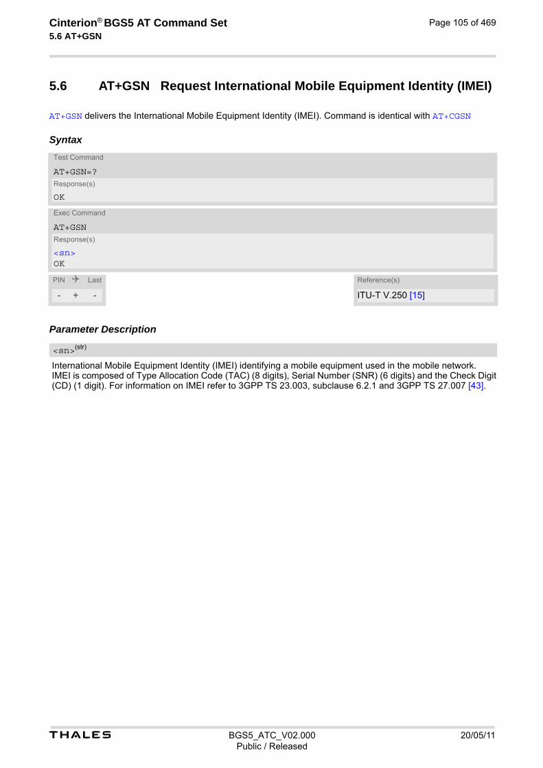
t BGS5_ATC_V02.000 20/05/11Public / Released
Cinterion® BGS5 AT Command Set 5.6 AT+GSN
Page 105 of 469
5.6 AT+GSN Request International Mobile Equipment Identity (IMEI)
AT+GSN delivers the International Mobile Equipment Identity (IMEI). Command is identical with AT+CGSN
Syntax
Parameter Description
International Mobile Equipment Identity (IMEI) identifying a mobile equipment used in the mobile network. IMEI is composed of Type Allocation Code (TAC) (8 digits), Serial Number (SNR) (6 digits) and the Check Digit (CD) (1 digit). For information on IMEI refer to 3GPP TS 23.003, subclause 6.2.1 and 3GPP TS 27.007 [43].
Test Command
AT+GSN=?Response(s)
OK
Exec Command
AT+GSNResponse(s)
<sn>OK
PIN Last Reference(s)
- + - ITU-T V.250 [15]
<sn>(str)
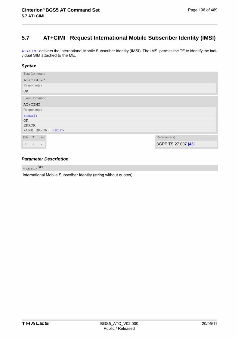
t BGS5_ATC_V02.000 20/05/11Public / Released
Cinterion® BGS5 AT Command Set 5.7 AT+CIMI
Page 106 of 469
5.7 AT+CIMI Request International Mobile Subscriber Identity (IMSI)
AT+CIMI delivers the International Mobile Subscriber Identity (IMSI). The IMSI permits the TE to identify the indi-vidual SIM attached to the ME.
Syntax
Parameter Description
International Mobile Subscriber Identity (string without quotes).
Test Command
AT+CIMI=?Response(s)
OK
Exec Command
AT+CIMIResponse(s)
<imsi>OKERROR+CME ERROR: <err>
PIN Last Reference(s)
+ + - 3GPP TS 27.007 [43]
<imsi>(str)
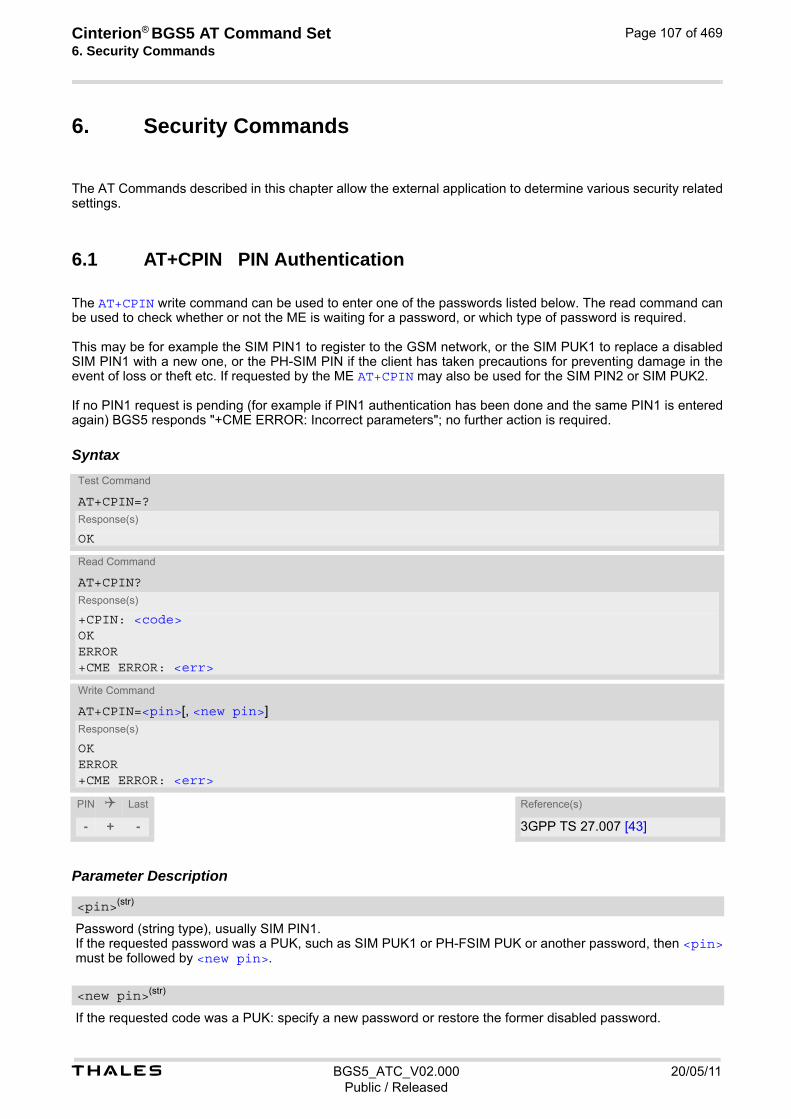
Cinterion® BGS5 AT Command Set 6. Security Commands
t BGS5_ATC_V02.000 20/05/11Public / Released
Page 107 of 469
6. Security Commands
The AT Commands described in this chapter allow the external application to determine various security related settings.
6.1 AT+CPIN PIN Authentication
The AT+CPIN write command can be used to enter one of the passwords listed below. The read command can be used to check whether or not the ME is waiting for a password, or which type of password is required. This may be for example the SIM PIN1 to register to the GSM network, or the SIM PUK1 to replace a disabled SIM PIN1 with a new one, or the PH-SIM PIN if the client has taken precautions for preventing damage in the event of loss or theft etc. If requested by the ME AT+CPIN may also be used for the SIM PIN2 or SIM PUK2. If no PIN1 request is pending (for example if PIN1 authentication has been done and the same PIN1 is entered again) BGS5 responds "+CME ERROR: Incorrect parameters"; no further action is required.
Syntax
Parameter Description
Password (string type), usually SIM PIN1. If the requested password was a PUK, such as SIM PUK1 or PH-FSIM PUK or another password, then <pin> must be followed by <new pin>.
If the requested code was a PUK: specify a new password or restore the former disabled password.
Test Command
AT+CPIN=?Response(s)
OK
Read Command
AT+CPIN?Response(s)
+CPIN: <code>OK ERROR +CME ERROR: <err>
Write Command
AT+CPIN=<pin>[, <new pin>]Response(s)
OK ERROR +CME ERROR: <err>
PIN Last Reference(s)
- + - 3GPP TS 27.007 [43]
<pin>(str)
<new pin>(str)

t BGS5_ATC_V02.000 20/05/11Public / Released
Cinterion® BGS5 AT Command Set 6.1 AT+CPIN
Page 108 of 469
SIM PIN authentication
READY PIN has already been entered. No further entry needed.
SIM PIN ME is waiting for SIM PIN1.
SIM PUK ME is waiting for SIM PUK1 if PIN1 was disabled after three failed attempts to enter PIN1.
SIM PIN2 ME is waiting for PIN2. This is only applicable when an attempt to access a PIN2 related feature was acknowledged with +CME ERROR: 17 ("SIM PIN2 required"), for example when the client attempts to edit the FD phonebook). In this case the read command AT+CPIN? also prompts for SIM PIN2. See also AT+CPIN2.
SIM PUK2 ME is waiting for PUK2 to unblock a disabled PIN2. As above, this is only nec-essary when the preceding command was acknowledged with +CME ERROR: 18 ("SIM PUK2 required") and only if the read command AT+CPIN? also prompts for SIM PUK2. See also AT+CPIN2.
Phone security locks set by client or factory
PH-SIM PIN ME is waiting for phone-to-SIM card password if "PS" lock is active and the cli-ent inserts other SIM card than the one used for the lock. ("PS" lock is also referred to as phone or antitheft lock).
PH-NET PUK ME is waiting for network personalisation unblocking password
PH-NETSUB PIN ME is waiting for network subset personalisation password
PH-NETSUB PUK ME is waiting for network subset unblocking password
PH-SP PIN ME is waiting for service provider personalisation password
PH-SP PUK ME is waiting for service provider personalisation unblocking password
PH-CORP PIN ME is waiting for corporate personalisation password
PH-CORP PUK ME is waiting for corprorate personalisation un-blocking password Notes• Successful PIN authentication only confirms that the entered PIN was recognized and correct. The output of
the result code OK does not necessarily imply that the mobile is registered to the desired network. Typical example: PIN was entered and accepted with OK, but the ME fails to register to the network. This may be due to missing network coverage, denied network access with currently used SIM card, no valid roaming agreement between home network and currently available operators etc. BGS5 offers various options to verify the present status of network registration: For example, the AT+COPS command indicates the currently used network. With AT+CREG you can also check the current status and acti-vate an unsolicited result code which appears whenever the status of the network registration changes (e.g. when the ME is powered up, or when the network cell changes).
• See AT+CPWD for information on passwords.
• See AT+CLCK for information on lock types.
<code>(text)

t BGS5_ATC_V02.000 20/05/11Public / Released
Cinterion® BGS5 AT Command Set 6.2 AT+CPIN2
Page 109 of 469
6.2 AT+CPIN2 PIN2 Authentication
AT+CPIN2 controls the authentication of SIM PIN2. The read command returns an alphanumeric string indicating whether or not SIM PIN2 authentication is required. The write command allows the BGS5 to verify the SIM PIN2 password. This may be for example the SIM PIN2 to benefit from the features listed below, or the SIM PUK2 to replace a PIN2 with a new one. Note that PIN2 can only be entered if PIN1 authentication was done. If the BGS5 is requesting SIM PUK2, use <pin> to enter the PUK2, followed by <new pin> to specify the new PIN2.
Syntax
Parameter Description
Password (string type), usually SIM PIN2 or, if requested, SIM PUK2.
If the requested code was SIM PUK2: new password (PIN2).
READY ME is not pending for any password.
SIM PIN2 ME is waiting for SIM PIN2. This <code> is returned only when PIN2 authentication has not yet been done or has failed ("+CME ERROR: 17").
SIM PUK2 ME is waiting for SIM PUK2. This <code> is returned only when PIN2 authentication has failed and ME is pending for SIM PUK2 (i.e. "+CME ERROR: 18").
Test Command
AT+CPIN2=?Response(s)
OK
Read Command
AT+CPIN2?Response(s)
+CPIN2: <code>OKERROR+CME ERROR: <err>
Write Command
AT+CPIN2=<pin>[, <new pin>]Response(s)
OKERROR+CME ERROR: <err>
PIN Last
- + -
<pin>(str)
<new pin>(str)
<code>(text)
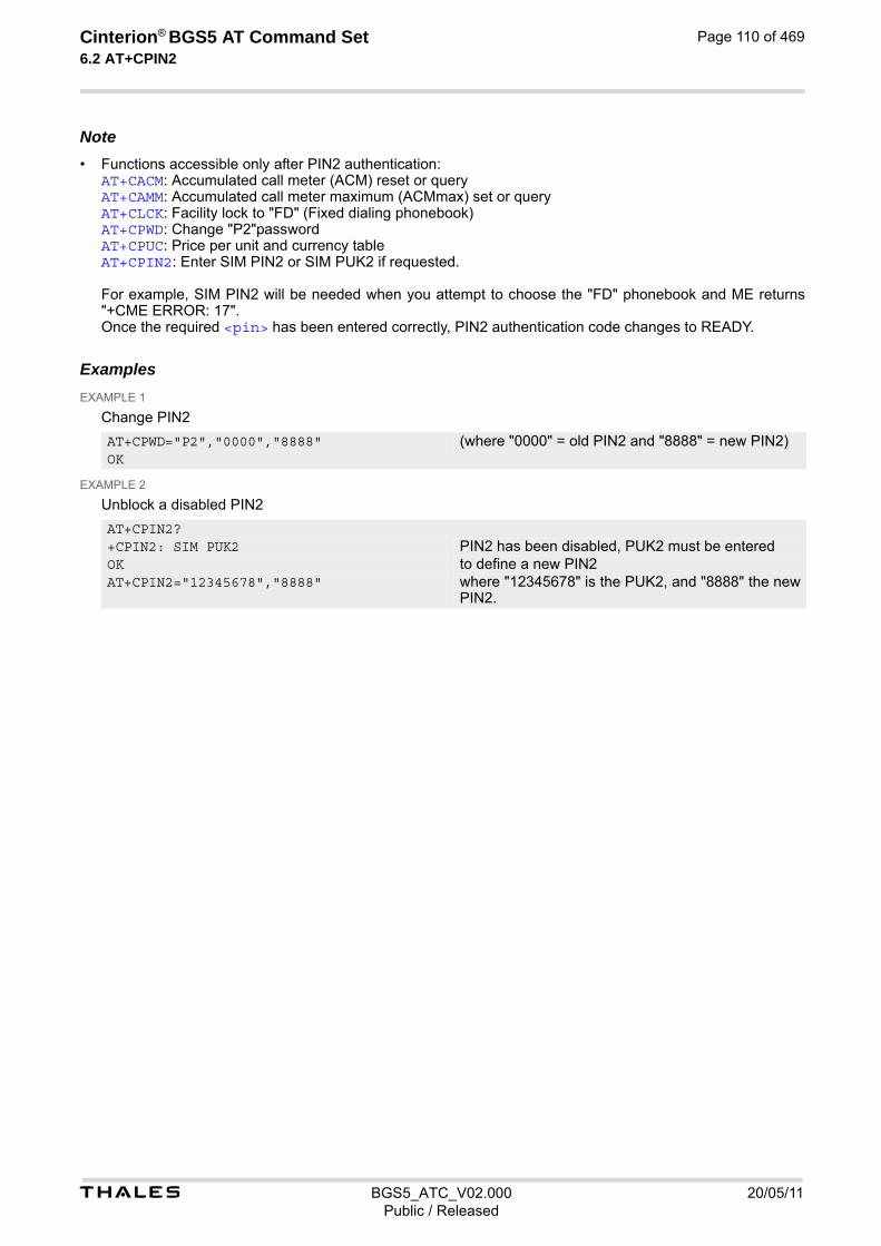
t BGS5_ATC_V02.000 20/05/11Public / Released
Cinterion® BGS5 AT Command Set 6.2 AT+CPIN2
Page 110 of 469
Note• Functions accessible only after PIN2 authentication:
AT+CACM: Accumulated call meter (ACM) reset or query AT+CAMM: Accumulated call meter maximum (ACMmax) set or query AT+CLCK: Facility lock to "FD" (Fixed dialing phonebook) AT+CPWD: Change "P2"password AT+CPUC: Price per unit and currency table AT+CPIN2: Enter SIM PIN2 or SIM PUK2 if requested. For example, SIM PIN2 will be needed when you attempt to choose the "FD" phonebook and ME returns "+CME ERROR: 17". Once the required <pin> has been entered correctly, PIN2 authentication code changes to READY.
Examples EXAMPLE 1
Change PIN2
EXAMPLE 2
Unblock a disabled PIN2
AT+CPWD="P2","0000","8888" (where "0000" = old PIN2 and "8888" = new PIN2) OK
AT+CPIN2?+CPIN2: SIM PUK2 PIN2 has been disabled, PUK2 must be entered OK to define a new PIN2 AT+CPIN2="12345678","8888" where "12345678" is the PUK2, and "8888" the new
PIN2.

t BGS5_ATC_V02.000 20/05/11Public / Released
Cinterion® BGS5 AT Command Set 6.3 AT+CLCK
Page 111 of 469
6.3 AT+CLCK Facility lock
AT+CLCK can be used to lock, unlock or interrogate a network or ME <facility>. The command can be aborted when network facilities are being set or interrogated.
Syntax
Parameter Description
Phone security locks set by client or factory
Primarily intended for the client to take safety precautions, "SC", "PS" and "FD" can be configured individually. "PS" may also be factory set.
“SC“ SIM (lock SIM cards) SIM requests password upon ME power-up and when this lock command is issued. <password>: SIM PIN1.
“PS“ PH SIM (lock PHone to SIM card). ME requests password when other than current SIM card is inserted. <pass-word>: PH-SIM PIN.
“FD“ SIM Fixed Dialing lock <password>: SIM PIN2. If "FD" lock is enabled numbers or public MMI *# codes can be used only if they start with matching numbers or characters stored in the "FD" phonebook. The capacity of the "FD" phonebook is depending on the SIM card.
Test Command
AT+CLCK=?Response(s)
+CLCK:list of supported <facility>s OK
Write Command
AT+CLCK=<facility>, <mode>[, <password>][, <class>]Response(s)
if <mode> is not equal 2 and command successful: OKif <mode>= 2 and command successful: +CLCK: <status>[, <class>][+CLCK: <status>[, <class>]][+CLCK: ...]OKERROR+CME ERROR: <err>
PIN Last Reference(s)
- ± - 3GPP TS 27.007 [43], 3GPP TS 22.004 [23], 3GPP TS 22.088 [31], 3GPP TS 23.088, 3GPP TS 24.088
<facility>(str)
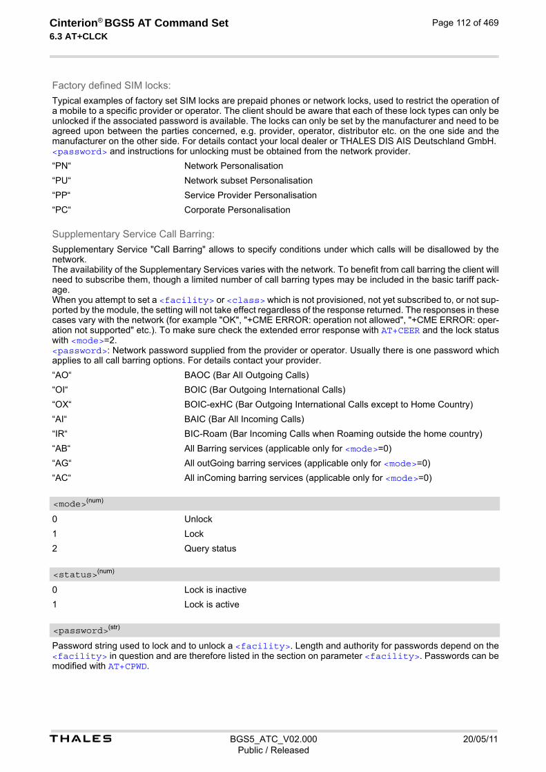
t BGS5_ATC_V02.000 20/05/11Public / Released
Cinterion® BGS5 AT Command Set 6.3 AT+CLCK
Page 112 of 469
Factory defined SIM locks:
Typical examples of factory set SIM locks are prepaid phones or network locks, used to restrict the operation of a mobile to a specific provider or operator. The client should be aware that each of these lock types can only be unlocked if the associated password is available. The locks can only be set by the manufacturer and need to be agreed upon between the parties concerned, e.g. provider, operator, distributor etc. on the one side and the manufacturer on the other side. For details contact your local dealer or THALES DIS AIS Deutschland GmbH. <password> and instructions for unlocking must be obtained from the network provider.
“PN“ Network Personalisation
“PU“ Network subset Personalisation
“PP“ Service Provider Personalisation
“PC“ Corporate Personalisation
Supplementary Service Call Barring:
Supplementary Service "Call Barring" allows to specify conditions under which calls will be disallowed by the network. The availability of the Supplementary Services varies with the network. To benefit from call barring the client will need to subscribe them, though a limited number of call barring types may be included in the basic tariff pack-age. When you attempt to set a <facility> or <class> which is not provisioned, not yet subscribed to, or not sup-ported by the module, the setting will not take effect regardless of the response returned. The responses in these cases vary with the network (for example "OK", "+CME ERROR: operation not allowed", "+CME ERROR: oper-ation not supported" etc.). To make sure check the extended error response with AT+CEER and the lock status with <mode>=2. <password>: Network password supplied from the provider or operator. Usually there is one password which applies to all call barring options. For details contact your provider.
“AO“ BAOC (Bar All Outgoing Calls)
“OI“ BOIC (Bar Outgoing International Calls)
“OX“ BOIC-exHC (Bar Outgoing International Calls except to Home Country)
“AI“ BAIC (Bar All Incoming Calls)
“IR“ BIC-Roam (Bar Incoming Calls when Roaming outside the home country)
“AB“ All Barring services (applicable only for <mode>=0)
“AG“ All outGoing barring services (applicable only for <mode>=0)
“AC“ All inComing barring services (applicable only for <mode>=0)
0 Unlock
1 Lock
2 Query status
0 Lock is inactive
1 Lock is active
Password string used to lock and to unlock a <facility>. Length and authority for passwords depend on the <facility> in question and are therefore listed in the section on parameter <facility>. Passwords can be modified with AT+CPWD.
<mode>(num)
<status>(num)
<password>(str)

t BGS5_ATC_V02.000 20/05/11Public / Released
Cinterion® BGS5 AT Command Set 6.3 AT+CLCK
Page 113 of 469
Integer or sum of integers each representing a class of information, i.e. a bearer service, telecommunication ser-vice or bearer service group as defined in 3GPP TS 22.004 [23].
1 Voice
2 Class 2 ("data") comprises all those individual data classes between 16 and 128, that are supported both by the network and the MS. This means, a setting made for class 2 applies to all individual data classes (if supported). In addition, you can assign a different setting to a specific class. For example, you can acti-vate Call Forwarding for all data classes, but deactivate it for data class 64, "dedicated packet access".
4 Fax
8 SMS
16 Data circuit sync
32 Data circuit async
64 Dedicated packet access
128 Dedicated PAD access
1...[7]...255 Combination of some of the above classes. For example, the default setting 7 represents the sum of the integers 1, 2 and 4 (voice, data and fax). The value 255 covers all classes. If parameter "class" is omitted, the default value 7 is used.
Note• The AT+CLCK command offers the full range of <class> parameters according to the 3GPP Technical Spec-
ifications. However, when you attempt to use a service option which is not provisioned or not yet subscribed to, the setting will not take effect regardless of the response returned. The responses in these cases vary with the network (for example "OK", "Operation not allowed", "Operation not supported" etc.). To make sure check the extended error response with AT+CEER and the lock status with <mode>=2.
Examples EXAMPLE 1
Lock SIM card (<facility>= "SC")
EXAMPLE 2
To query the status of the SIM card lock:
<class>(num)
AT+CLCK="SC",1,"9999" The "SC" parameter enables or disables the SIM PIN authentication (PIN 1) when you power up the ME.
OK SIM card locked. As a result, SIM PIN 1 must be entered to enable ME to register to the network.
AT+CLCK="SC",0,"9999" Unlocks SIM card. OK When powered up, ME registers to the network without requesting SIM
PIN1. Note: Depending on the services offered by the provider, this feature is not supported by all SIM card types. If so, the command returns ERROR when you attempt to unlock the card.
AT+CLCK="SC",2 Query the status of SIM card lock. +CLCK: 1 SIM card is locked. SIM PIN1 must be entered to enable ME to register
to the network. OK
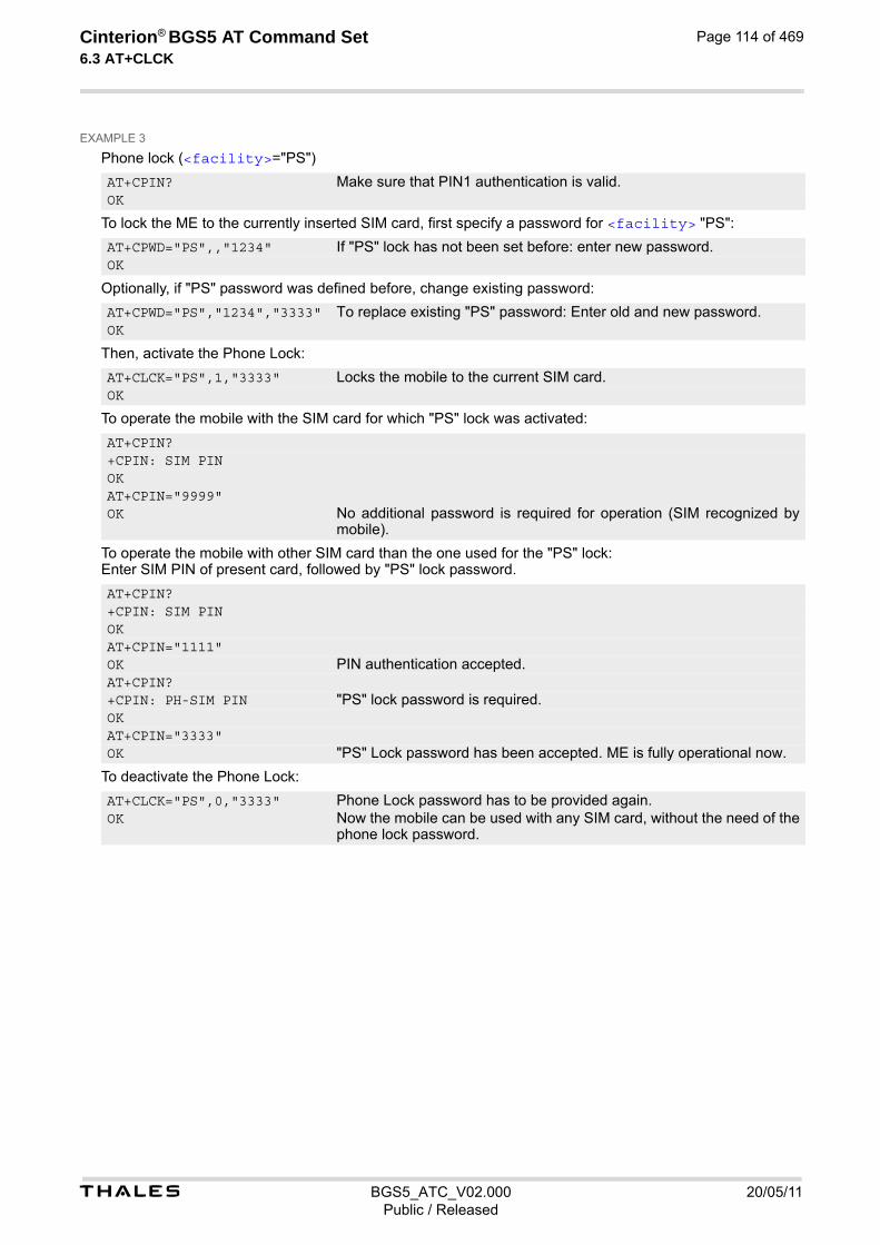
t BGS5_ATC_V02.000 20/05/11Public / Released
Cinterion® BGS5 AT Command Set 6.3 AT+CLCK
Page 114 of 469
EXAMPLE 3
Phone lock (<facility>="PS")
To lock the ME to the currently inserted SIM card, first specify a password for <facility> "PS":
Optionally, if "PS" password was defined before, change existing password:
Then, activate the Phone Lock:
To operate the mobile with the SIM card for which "PS" lock was activated:
To operate the mobile with other SIM card than the one used for the "PS" lock: Enter SIM PIN of present card, followed by "PS" lock password.
To deactivate the Phone Lock:
AT+CPIN? Make sure that PIN1 authentication is valid. OK
AT+CPWD="PS",,"1234" If "PS" lock has not been set before: enter new password. OK
AT+CPWD="PS","1234","3333" To replace existing "PS" password: Enter old and new password. OK
AT+CLCK="PS",1,"3333" Locks the mobile to the current SIM card. OK
AT+CPIN? +CPIN: SIM PIN OK AT+CPIN="9999" OK No additional password is required for operation (SIM recognized by
mobile).
AT+CPIN? +CPIN: SIM PIN OK AT+CPIN="1111" OK PIN authentication accepted. AT+CPIN? +CPIN: PH-SIM PIN "PS" lock password is required. OK AT+CPIN="3333" OK "PS" Lock password has been accepted. ME is fully operational now.
AT+CLCK="PS",0,"3333" Phone Lock password has to be provided again. OK Now the mobile can be used with any SIM card, without the need of the
phone lock password.
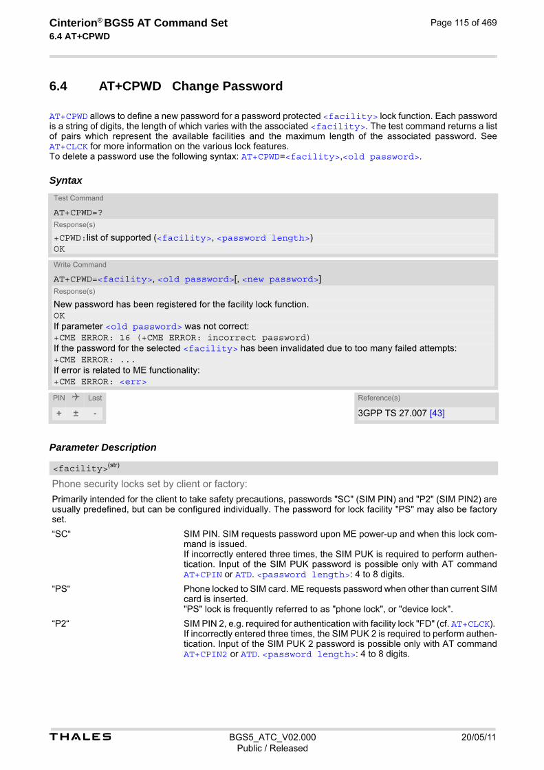
t BGS5_ATC_V02.000 20/05/11Public / Released
Cinterion® BGS5 AT Command Set 6.4 AT+CPWD
Page 115 of 469
6.4 AT+CPWD Change Password
AT+CPWD allows to define a new password for a password protected <facility> lock function. Each password is a string of digits, the length of which varies with the associated <facility>. The test command returns a list of pairs which represent the available facilities and the maximum length of the associated password. See AT+CLCK for more information on the various lock features. To delete a password use the following syntax: AT+CPWD=<facility>,<old password>.
Syntax
Parameter Description
Phone security locks set by client or factory:
Primarily intended for the client to take safety precautions, passwords "SC" (SIM PIN) and "P2" (SIM PIN2) are usually predefined, but can be configured individually. The password for lock facility "PS" may also be factory set.
“SC“ SIM PIN. SIM requests password upon ME power-up and when this lock com-mand is issued. If incorrectly entered three times, the SIM PUK is required to perform authen-tication. Input of the SIM PUK password is possible only with AT command AT+CPIN or ATD. <password length>: 4 to 8 digits.
“PS“ Phone locked to SIM card. ME requests password when other than current SIM card is inserted. "PS" lock is frequently referred to as "phone lock", or "device lock".
“P2“ SIM PIN 2, e.g. required for authentication with facility lock "FD" (cf. AT+CLCK). If incorrectly entered three times, the SIM PUK 2 is required to perform authen-tication. Input of the SIM PUK 2 password is possible only with AT command AT+CPIN2 or ATD. <password length>: 4 to 8 digits.
Test Command
AT+CPWD=?Response(s)
+CPWD:list of supported (<facility>, <password length>) OK
Write Command
AT+CPWD=<facility>, <old password>[, <new password>]Response(s)
New password has been registered for the facility lock function. OKIf parameter <old password> was not correct:+CME ERROR: 16 (+CME ERROR: incorrect password)If the password for the selected <facility> has been invalidated due to too many failed attempts:+CME ERROR: ...If error is related to ME functionality: +CME ERROR: <err>
PIN Last Reference(s)
+ ± - 3GPP TS 27.007 [43]
<facility>(str)

t BGS5_ATC_V02.000 20/05/11Public / Released
Cinterion® BGS5 AT Command Set 6.4 AT+CPWD
Page 116 of 469
Factory defined SIM locks:
Typical examples of factory set SIM locks are prepaid phones or network locks, used to restrict the operation of a mobile to a specific provider or operator. The client should be aware that each of these lock types can only be unlocked if the associated password is available. The locks can only be set by the manufacturer and need to be agreed upon between the parties concerned, e.g. provider, operator, distributor etc. on the one side and the manufacturer on the other side. For details contact your local dealer or THALES DIS AIS Deutschland GmbH.
“PN“ Network Personalisation
“PU“ Network subset Personalisation
“PP“ Service Provider Personalisation
“PC“ Corporate Personalisation
Supplementary Service Call Barring:
Supplementary Service "Call Barring" allows to specify conditions under which calls will be disallowed by the network. The availability of the Supplementary Services varies with the network. To benefit from call barring the client will need to subscribe them, though a limited number of call barring types may be included in the basic tariff pack-age. <password length>: The Network Password needs to be supplied from the network provider or network oper-ator. Usually there is one 4 digit password which applies to all call barring options. For details contact your pro-vider.
“AO“ BAOC (Bar All Outgoing Calls)
“OI“ BOIC (Bar Outgoing International Calls)
“OX“ BOIC-exHC (Bar Outgoing International Calls except to Home Country)
“AI“ BAIC (Bar All Incoming Calls)
“IR“ BIC-Roam (Bar Incoming Calls when Roaming outside the home country)
“AB“ All Barring services
“AG“ All outGoing barring services
“AC“ All inComing barring services
4...16 Length of password. The range of permitted length for a password depends on the associated <facility>. It is available from the test command response, or in the description of parameter <facility>.
Password specified for the facility. Parameter <old password> can be ignored if no old password was allocated to the facility.
New password. Mandatory, if <old password> was an unblocking key. Note• When changing PIN2 (<facility>="P2") it is recommended to check the new state of PIN2 by using the
AT+CPIN2 command.
Examples EXAMPLE 1
To change PIN2
<password length>(num)
<old password>(str)
<new password>(str)

t BGS5_ATC_V02.000 20/05/11Public / Released
Cinterion® BGS5 AT Command Set 6.4 AT+CPWD
Page 117 of 469
EXAMPLE 2
To set password used to enable or disable barring of all outgoing calls:
AT+CPWD="P2","0000","8888" (where "0000" = old PIN2 and "8888" = new PIN2) OK PIN2 Password has been changed to "8888"
AT+CPWD="AO","0000","3333" Requests the network to change the password for supplementary service "call barring".
OK Usually this request will affect all barring services, even though the request is issued for Supplementary Service BAOC ("Barring of all outgoing calls") only. Refer to the respective network provider for detail.

Cinterion® BGS5 AT Command Set 7. Call related Commands
t BGS5_ATC_V02.000 20/05/11Public / Released
Page 118 of 469
7. Call related Commands
The AT Commands described in this chapter are related to Mobile Originated (MOC, i.e. outgoing) Calls and Mobile Terminated (MTC, i.e. incoming) Calls.
7.1 ATA Connect to Incoming Call
ATA connects the BGS5 to an incoming voice or CS data call which is indicated by a "RING" URC. ATA can also be used to accept a NW-initiated Request PDP Context Activation message in GSM. For details please refer to ATA and AT+CGAUTO. AT+CRC allows to change the format of the RING URC.
Syntax
Parameter Description
Connection speed
Presented only if ATX parameter setting is greater 0. Possible connection speed values:
“2400“
“4800“
“9600“ Notes• Additional AT commands on the same command line are ignored.
• ATA may be aborted if receiving a character during execution. It can't be aborted in some connection setup states, such as handshaking.
Exec Command
ATAResponse(s)
In case of incoming CS data call, if successfully connected (ME switches to data mode): CONNECT <text>In case of voice call, if successfully connected: OKIf incoming call is not available, i.e. already disconnected or hanged up: NO CARRIER
PIN Last Reference(s)
+ - - ITU-T V.250 [15]
<text>(str)

t BGS5_ATC_V02.000 20/05/11Public / Released
Cinterion® BGS5 AT Command Set 7.2 ATD
Page 119 of 469
7.2 ATD Mobile originated call to specified number
ATD can be used to set up outgoing voice or CS data calls. It can also be used to send *# codes for Supplemen-tary Services and other functions. The termination character ";" shall be added when a voice call is originated. Using ATD during an active call:
• When a user originates a second voice call while there is already an active voice call, the first call will auto-matically be put on hold.
Syntax
Parameter Description
String of dialing digits and optional V.250 modifiers: 0-9, *, #, +, A, B, C The following V.250 modifiers are ignored: ,(comma), T, !, W ,@
String of GSM modifiers: I Activates CLIR (disables presentation of own phone number to called party, if no *#31#-code is within the dial string) i Deactivates CLIR (enables presentation of own phone number to called party, if no *#31#-code is within the dial string) G Activate Closed User Group explicit invocation for this call only. g Deactivate Closed User Group explicit invocation for this call only.
Exec Command
ATD<n>[<mgsm>][;]Response(s)
If successfully connected and non-voice call (ME switches to online data mode):CONNECT <text>If voice call and command input is completed:OKIf no dialtone (parameter setting ATX3 or ATX4):NO DIALTONEIf busy (parameter setting ATX3 or ATX4):BUSYIf connection cannot be set up:NO CARRIERNO ANSWERERROR+CME ERROR: <err>
PIN Last Reference(s)
± - - ITU-T V.250 [15]
<n>(text)
<mgsm>(str)
t BGS5_ATC_V02.000 20/05/11Public / Released
Cinterion® BGS5 AT Command Set 7.2 ATD
Page 120 of 469
Notes• <mgsm> is not supported for data calls.
• <n> is default for last number that can be dialed by ATDL.
• See also ATX for <text>.
• Parameter 'G' or 'g' will be ignored if Closed User Group was already activated, respectively deactivated with AT+CCUG command before. Call by call invocation of CUG uses the settings provisioned by the provider or, if available, the settings of the parameters <index> and <info> made with AT+CCUG.
• Dialing A, B, C as DTMF tone is not supported.
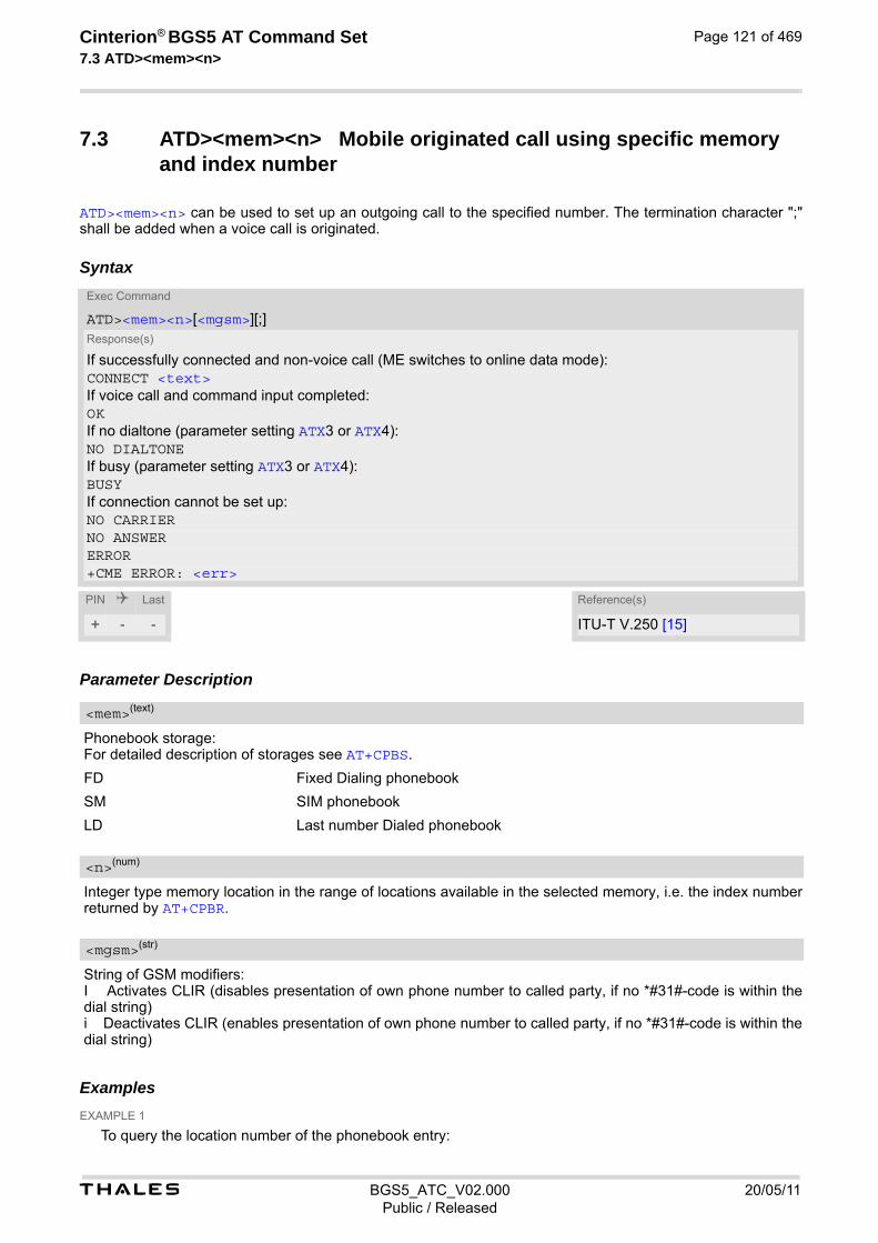
t BGS5_ATC_V02.000 20/05/11Public / Released
Cinterion® BGS5 AT Command Set 7.3 ATD><mem><n>
Page 121 of 469
7.3 ATD><mem><n> Mobile originated call using specific memory and index number
ATD><mem><n> can be used to set up an outgoing call to the specified number. The termination character ";" shall be added when a voice call is originated.
Syntax
Parameter Description
Phonebook storage: For detailed description of storages see AT+CPBS.
FD Fixed Dialing phonebook
SM SIM phonebook
LD Last number Dialed phonebook
Integer type memory location in the range of locations available in the selected memory, i.e. the index number returned by AT+CPBR.
String of GSM modifiers: I Activates CLIR (disables presentation of own phone number to called party, if no *#31#-code is within the dial string) i Deactivates CLIR (enables presentation of own phone number to called party, if no *#31#-code is within the dial string)
Examples EXAMPLE 1
To query the location number of the phonebook entry:
Exec Command
ATD><mem><n>[<mgsm>][;]Response(s)
If successfully connected and non-voice call (ME switches to online data mode):CONNECT <text>If voice call and command input completed:OKIf no dialtone (parameter setting ATX3 or ATX4):NO DIALTONEIf busy (parameter setting ATX3 or ATX4):BUSYIf connection cannot be set up:NO CARRIERNO ANSWERERROR+CME ERROR: <err>
PIN Last Reference(s)
+ - - ITU-T V.250 [15]
<mem>(text)
<n>(num)
<mgsm>(str)
t BGS5_ATC_V02.000 20/05/11Public / Released
Cinterion® BGS5 AT Command Set 7.3 ATD><mem><n>
Page 122 of 469
TA returns the entries available in the active phonebook.
EXAMPLE 2
To dial a number from the SIM phonebook, for example the number stored to location 15:
EXAMPLE 3
To dial a phone number stored in the last dial memory on the SIM card:
AT+CPBR=1,xx
ATD>SM15;OK
ATD>LD9;OK

t BGS5_ATC_V02.000 20/05/11Public / Released
Cinterion® BGS5 AT Command Set 7.4 ATD><n>
Page 123 of 469
7.4 ATD><n> Mobile originated call from active memory using index number
ATD><n> can be used to set up an outgoing call to the stored number. The termination character ";" shall be added when a voice call is originated.
Syntax
Parameter Description
Integer type memory location in the range of locations available in the selected memory, i.e. the index number returned by AT+CPBR.
String of GSM modifiers: I Activates CLIR (disables presentation of own phone number to called party) i Deactivates CLIR (enables presentation of own phone number to called party)
Note• Parameter <mgsm> only if no *# code is within the dialing string.
Exec Command
ATD><n>[<mgsm>][;]Response(s)
If successfully connected and non-voice call (ME switches to online data mode):CONNECT <text>If voice call and command input is completed:OKIf no dialtone (parameter setting ATX3 or ATX4):NO DIALTONEIf busy (parameter setting ATX3 or ATX4):BUSYIf connection cannot be set up:NO CARRIERNO ANSWERERROR+CME ERROR: <err>
PIN Last Reference(s)
+ - - ITU-T V.250 [15]
<n>(num)
<mgsm>(str)
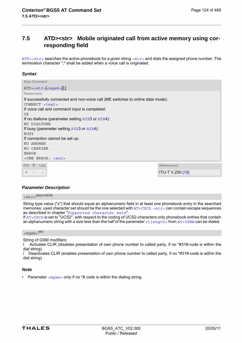
t BGS5_ATC_V02.000 20/05/11Public / Released
Cinterion® BGS5 AT Command Set 7.5 ATD><str>
Page 124 of 469
7.5 ATD><str> Mobile originated call from active memory using cor-responding field
ATD><str> searches the active phonebook for a given string <str> and dials the assigned phone number. The termination character ";" shall be added when a voice call is originated.
Syntax
Parameter Description
String type value ("x") that should equal an alphanumeric field in at least one phonebook entry in the searched memories; used character set should be the one selected with AT+CSCS. <str> can contain escape sequences as described in chapter "Supported character sets". If AT+CSCS is set to "UCS2", with respect to the coding of UCS2-characters only phonebook entries that contain an alphanumeric string with a size less than the half of the parameter <tlength> from AT+CPBW can be dialed.
String of GSM modifiers: I Activates CLIR (disables presentation of own phone number to called party, if no *#31#-code is within the dial string) i Deactivates CLIR (enables presentation of own phone number to called party, if no *#31#-code is within the dial string)
Note• Parameter <mgsm> only if no *# code is within the dialing string.
Exec Command
ATD><str>[<mgsm>][;]Response(s)
If successfully connected and non-voice call (ME switches to online data mode):CONNECT <text>If voice call and command input is completed:OKIf no dialtone (parameter setting ATX3 or ATX4):NO DIALTONEIf busy (parameter setting ATX3 or ATX4):BUSYIf connection cannot be set up:NO ANSWERNO CARRIERERROR+CME ERROR: <err>
PIN Last Reference(s)
+ - - ITU-T V.250 [15]
<str>(str)(+CSCS)
<mgsm>(str)

t BGS5_ATC_V02.000 20/05/11Public / Released
Cinterion® BGS5 AT Command Set 7.6 ATDL
Page 125 of 469
7.6 ATDL Redial last number used
ATDL redials the last voice and data call number used in the ATD command. If terminated with semicolon ";" ATDL dials the last voice call number stored in the "LD" phonebook. Otherwise, ATDL dials the last data call num-ber (not contained in the "LD" phonebook).
SyntaxExec Command
ATDL[;]Response(s)
If successfully connected and non-voice call (ME switches to online data mode):CONNECT <text>If voice call and command input is completed:OKIf no dialtone (parameter setting ATX3 or ATX4):NO DIALTONEIf busy (parameter setting ATX3 or ATX4):BUSYIf connection cannot be set up:NO CARRIERNO ANSWERERROR+CME ERROR: <err>
PIN Last Reference(s)
+ - - ITU-T V.250 [15]

t BGS5_ATC_V02.000 20/05/11Public / Released
Cinterion® BGS5 AT Command Set 7.7 ATH
Page 126 of 469
7.7 ATH Disconnect existing connection
ATH releases all active calls and held calls, but not waiting calls. ATH releases a CS data call.
Syntax
Parameter Description
[0] Disconnect from command line and terminate connection Note• ATH terminates every circuit switched call ( voice or data), even if it is issued via another interface. This behav-
ior is in accordance with ITU-T V.250; (07/97, "Hook control": "ATH is terminating any call in progress.").
Exec Command
ATH[<n>]Response(s)
OK
PIN Last Reference(s)
- - - ITU-T V.250 [15]
<n>(num)
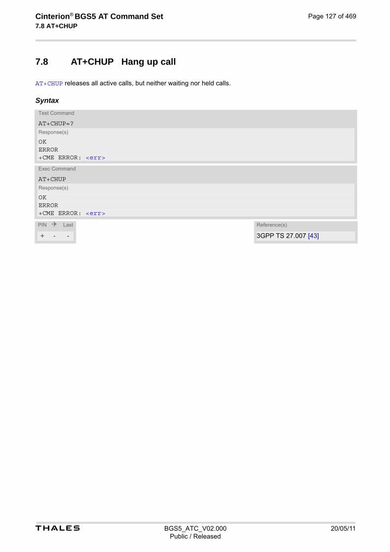
t BGS5_ATC_V02.000 20/05/11Public / Released
Cinterion® BGS5 AT Command Set 7.8 AT+CHUP
Page 127 of 469
7.8 AT+CHUP Hang up call
AT+CHUP releases all active calls, but neither waiting nor held calls.
SyntaxTest Command
AT+CHUP=?Response(s)
OKERROR+CME ERROR: <err>
Exec Command
AT+CHUPResponse(s)
OKERROR+CME ERROR: <err>
PIN Last Reference(s)
+ - - 3GPP TS 27.007 [43]
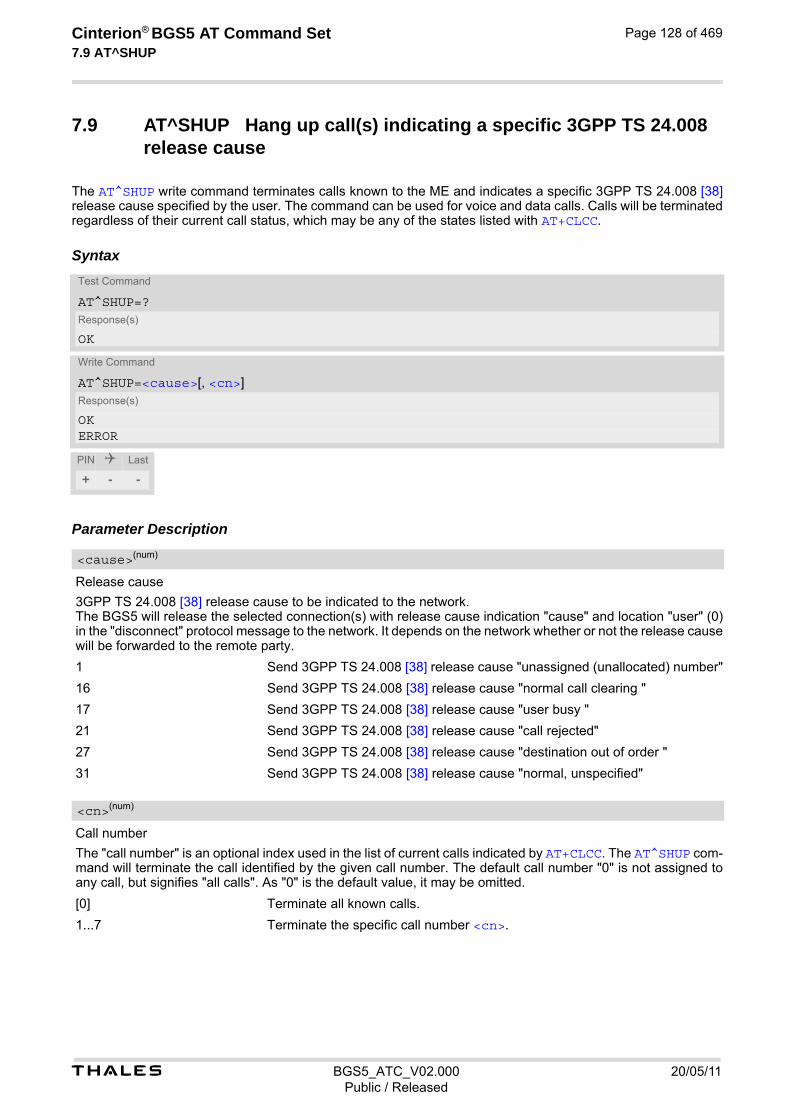
t BGS5_ATC_V02.000 20/05/11Public / Released
Cinterion® BGS5 AT Command Set 7.9 AT^SHUP
Page 128 of 469
7.9 AT^SHUP Hang up call(s) indicating a specific 3GPP TS 24.008 release cause
The AT^SHUP write command terminates calls known to the ME and indicates a specific 3GPP TS 24.008 [38] release cause specified by the user. The command can be used for voice and data calls. Calls will be terminated regardless of their current call status, which may be any of the states listed with AT+CLCC.
Syntax
Parameter Description
Release cause
3GPP TS 24.008 [38] release cause to be indicated to the network. The BGS5 will release the selected connection(s) with release cause indication "cause" and location "user" (0) in the "disconnect" protocol message to the network. It depends on the network whether or not the release cause will be forwarded to the remote party.
1 Send 3GPP TS 24.008 [38] release cause "unassigned (unallocated) number"
16 Send 3GPP TS 24.008 [38] release cause "normal call clearing "
17 Send 3GPP TS 24.008 [38] release cause "user busy "
21 Send 3GPP TS 24.008 [38] release cause "call rejected"
27 Send 3GPP TS 24.008 [38] release cause "destination out of order "
31 Send 3GPP TS 24.008 [38] release cause "normal, unspecified"
Call number
The "call number" is an optional index used in the list of current calls indicated by AT+CLCC. The AT^SHUP com-mand will terminate the call identified by the given call number. The default call number "0" is not assigned to any call, but signifies "all calls". As "0" is the default value, it may be omitted.
[0] Terminate all known calls.
1...7 Terminate the specific call number <cn>.
Test Command
AT^SHUP=?Response(s)
OK
Write Command
AT^SHUP=<cause>[, <cn>]Response(s)
OKERROR
PIN Last
+ - -
<cause>(num)
<cn>(num)

t BGS5_ATC_V02.000 20/05/11Public / Released
Cinterion® BGS5 AT Command Set 7.10 ATS0
Page 129 of 469
7.10 ATS0 Set number of rings before automatically answering a call
ATS0 controls the automatic answering feature for data calls. The setting is global for all interfaces, but an incom-ing call is answered only on the interface where the ATS0 write command was executed most recently. An excep-tion is the second serial interface ASC1: Take care not to activate autoanswering on ASC1, because on this interface calls might be autoanswered regardless whether the connection can be handled. The write command is SIM PIN protected, the read command is not.
Syntax
Parameter Description
000(&F)(D) Automatic answer mode is disabled.
001-255 Enable automatic answering after specified number of rings.
Read Command
ATS0?Response(s)
<n>OKERROR
Write Command
ATS0=<n>Response(s)
OKERROR
PIN Last Reference(s)
± - - ITU-T V.250 [15]
<n>(num)(&V)(&W)
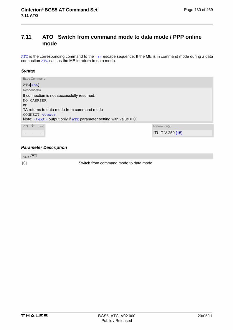
t BGS5_ATC_V02.000 20/05/11Public / Released
Cinterion® BGS5 AT Command Set 7.11 ATO
Page 130 of 469
7.11 ATO Switch from command mode to data mode / PPP online mode
ATO is the corresponding command to the +++ escape sequence: If the ME is in command mode during a data connection ATO causes the ME to return to data mode.
Syntax
Parameter Description
[0] Switch from command mode to data mode
Exec Command
ATO[<n>]Response(s)
If connection is not successfully resumed:NO CARRIERorTA returns to data mode from command modeCONNECT <text>Note: <text> output only if ATX parameter setting with value > 0.
PIN Last Reference(s)
- - - ITU-T V.250 [15]
<n>(num)
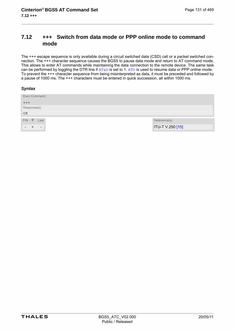
t BGS5_ATC_V02.000 20/05/11Public / Released
Cinterion® BGS5 AT Command Set 7.12 +++
Page 131 of 469
7.12 +++ Switch from data mode or PPP online mode to command mode
The +++ escape sequence is only available during a circuit switched data (CSD) call or a packet switched con-nection. The +++ character sequence causes the BGS5 to pause data mode and return to AT command mode. This allows to enter AT commands while maintaining the data connection to the remote device. The same task can be performed by toggling the DTR line if AT&D is set to 1. ATO is used to resume data or PPP online mode. To prevent the +++ character sequence from being misinterpreted as data, it must be preceded and followed by a pause of 1000 ms. The +++ characters must be entered in quick succession, all within 1000 ms.
SyntaxExec Command
+++Response(s)
OK
PIN Last Reference(s)
- + - ITU-T V.250 [15]

t BGS5_ATC_V02.000 20/05/11Public / Released
Cinterion® BGS5 AT Command Set 7.13 AT+CBST
Page 132 of 469
7.13 AT+CBST Select Bearer Service Type
AT+CBST write command selects the bearer service <name>, the data rate <speed> and the connection element <ce> to be used when data calls are originated. The settings are global for all interfaces, and also apply to mobile terminated data calls. See 3GPP TS 22.002 [22] for a list of allowed combinations of subparameters.
Syntax
Parameter Description
0 Automatic Speed Selection
4 2400 bps (V.22bis)
6 4800 bps (V.32)
7(&F) 9600 bps (V.32)
68 2400 bps (V.110)
70 4800 bps (V.110)
71(P) 9600 bps (V.110)
0(&F) Asynchronous modem (UDI or 3.1 kHz modem)
1 Synchronous modem (UDI or 3.1 kHz modem)
4 Asynchronous modem (RDI)
5 Synchronous modem (RDI)
0 Transparent
Test Command
AT+CBST=?Response(s)
+CBST: (list of supported<speed>s), (list of supported<name>s), (list of supported<ce>s)OK
Read Command
AT+CBST?Response(s)
+CBST: <speed>, <name>, <ce>OK
Write Command
AT+CBST=<speed>[, <name>[, <ce>]]Response(s)
OKERROR
PIN Last Reference(s)
- + - 3GPP TS 27.007 [43], 3GPP TS 22.002 [22]
<speed>(num)(&V)(&W)
<name>(num)(&W)
<ce>(num)(&W)
t BGS5_ATC_V02.000 20/05/11Public / Released
Cinterion® BGS5 AT Command Set 7.13 AT+CBST
Page 133 of 469
1(&F) Non-transparent
2 Both, transparent preferred
3 Both, non-transparent preferred

t BGS5_ATC_V02.000 20/05/11Public / Released
Cinterion® BGS5 AT Command Set 7.14 AT+CSTA
Page 134 of 469
7.14 AT+CSTA Select type of address
Set command selects the type of number for further dialing commands ATD according to 3GPP Technical Spec-ifications.
Syntax
Parameter Description
145 When dialing string includes international access code character "+"
129 Otherwise
Test Command
AT+CSTA=?Response(s)
+CSTA: (list of supported<type>s)OK
Read Command
AT+CSTA?Response(s)
+CSTA: <type>OK
Write Command
AT+CSTA=<type>Response(s)
OKERROR
PIN Last Reference(s)
- + - 3GPP TS 27.007 [43]
<type>(num)

t BGS5_ATC_V02.000 20/05/11Public / Released
Cinterion® BGS5 AT Command Set 7.15 AT+CRLP
Page 135 of 469
7.15 AT+CRLP Configure RLP Parameters for Outgoing Non-Trans-parent Data Calls
The AT+CRLP write command sets radio link protocol (RLP) parameters used when non-transparent data calls are originated. The read command returns the current settings for the supported RLP version 0.
Syntax
Parameter Description
Interworking window size (IWF to MS)
0...61(&F)
Mobile window size (MS to IWF)
0...61(&F)
Acknowledgement timer (T1 in 10 ms units)
48...[78](&F)...255
Re-transmission attempts N2
1...6(&F)...255
Test Command
AT+CRLP=?Response(s)
+CRLP: (list of supported<iws>s), (list of supported<mws>s), (list of supported<T1>s), (list of supported<N2>s)OK
Read Command
AT+CRLP?Response(s)
+CRLP: <iws>, <mws>, <T1>, <N2>OK
Write Command
AT+CRLP=[<iws>[, <mws>[, <T1>[, <N2>]]]]Response(s)
OKERROR+CME ERROR: <err>
PIN Last Reference(s)
- + - 3GPP TS 27.007 [43]
<iws>(num)(&V)(&W)
<mws>(num)(&V)(&W)
<T1>(num)(&V)(&W)
<N2>(num)(&V)(&W)

t BGS5_ATC_V02.000 20/05/11Public / Released
Cinterion® BGS5 AT Command Set 7.16 AT+CLCC
Page 136 of 469
7.16 AT+CLCC List of current calls
The execute command lists all current calls. If the command is successful, but no calls are available, no infor-mation response is sent to TE.
Syntax
Parameter Description
Call identification number as described in subclause 6.5.5.1 of 3GPP TS 22.030 [24]. This number can be used in AT+CHLD command operations
0 Mobile originated call (MOC)
1 Mobile terminated call (MTC)
State of the call
0 Active
1 Held
2 Dialing (MOC)
3 Alerting (MOC)
4 Incoming (MTC)
5 Waiting (MTC)
Bearer/teleservice
0 Voice
1 Data
Test Command
AT+CLCC=?Response(s)
OK
Exec Command
AT+CLCCResponse(s)
[+CLCC: <idx>, <dir>, <stat>, <mode>, <mpty>[, <number>, <type>[, <alpha>]]][+CLCC: <idx>, <dir>, <stat>, <mode>, <mpty>[, <number>, <type>[, <alpha>]]][+CLCC: ...]OKERROR+CME ERROR: <err>
PIN Last Reference(s)
+ - - 3GPP TS 27.007 [43]
<idx>(num)
<dir>(num)
<stat>(num)
<mode>(num)

t BGS5_ATC_V02.000 20/05/11Public / Released
Cinterion® BGS5 AT Command Set 7.16 AT+CLCC
Page 137 of 469
3 Voice followed by data, voice mode
9 Unknown
0 Call is not one of multiparty (conference) call parties
1 Call is one of multiparty (conference) call parties
Phone number in format specified by <type>
Type of address octet as defined by 3GPP TS 24.008 [38], subclause 10.5.4.7. For possible values see the <type> parameters specified for phonebook related AT commands, for example AT+CPBR and AT+CPBW.
145 Dialing string <number> includes international access code character '+'
161 National number
128 Number is restricted
129 Otherwise
Alphanumeric representation of <number> corresponding to the entry found in phonebook (see for example AT+CPBW, parameter <text>). Due to time constraints on the necessary evaluation of the phonebook, this parameter may show a default value in early call phases (e.g. for <stat>= ''dialing'', ''incoming'' or ''alerting''), even if a phonebook entry is present for the number concerned.
<mpty>(num)
<number>(str)
<type>(num)
<alpha>(str)(+CSCS)
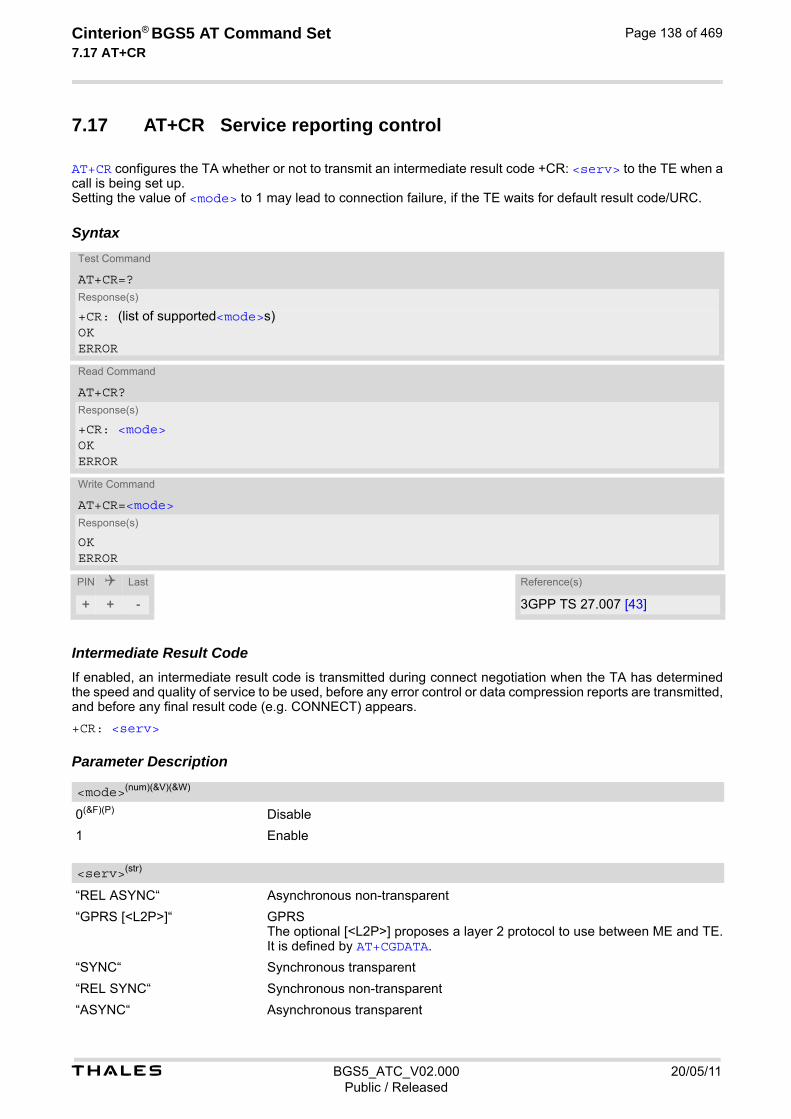
t BGS5_ATC_V02.000 20/05/11Public / Released
Cinterion® BGS5 AT Command Set 7.17 AT+CR
Page 138 of 469
7.17 AT+CR Service reporting control
AT+CR configures the TA whether or not to transmit an intermediate result code +CR: <serv> to the TE when a call is being set up. Setting the value of <mode> to 1 may lead to connection failure, if the TE waits for default result code/URC.
Syntax
Intermediate Result CodeIf enabled, an intermediate result code is transmitted during connect negotiation when the TA has determined the speed and quality of service to be used, before any error control or data compression reports are transmitted, and before any final result code (e.g. CONNECT) appears.
+CR: <serv> Parameter Description
0(&F)(P) Disable
1 Enable
“REL ASYNC“ Asynchronous non-transparent
“GPRS [<L2P>]“ GPRS The optional [<L2P>] proposes a layer 2 protocol to use between ME and TE. It is defined by AT+CGDATA.
“SYNC“ Synchronous transparent
“REL SYNC“ Synchronous non-transparent
“ASYNC“ Asynchronous transparent
Test Command
AT+CR=?Response(s)
+CR: (list of supported<mode>s)OKERROR
Read Command
AT+CR?Response(s)
+CR: <mode>OKERROR
Write Command
AT+CR=<mode>Response(s)
OKERROR
PIN Last Reference(s)
+ + - 3GPP TS 27.007 [43]
<mode>(num)(&V)(&W)
<serv>(str)
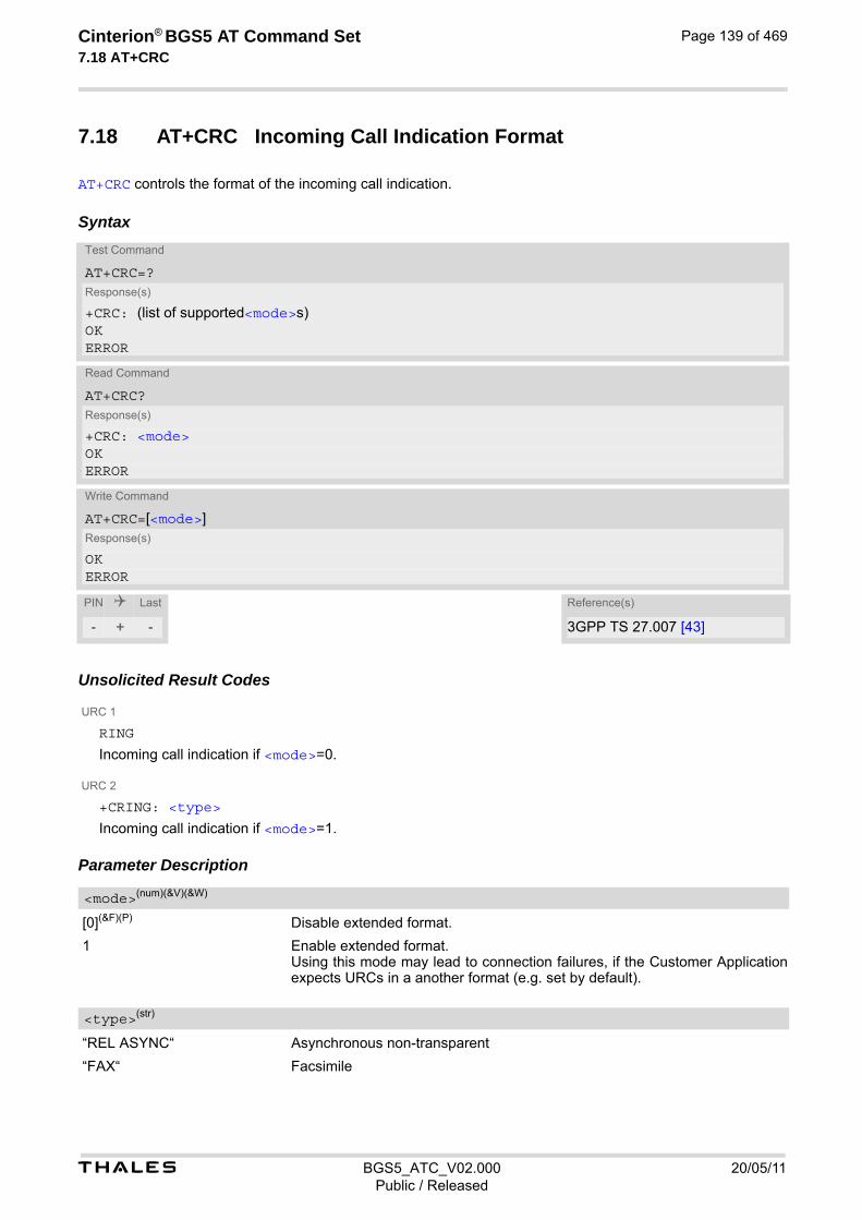
t BGS5_ATC_V02.000 20/05/11Public / Released
Cinterion® BGS5 AT Command Set 7.18 AT+CRC
Page 139 of 469
7.18 AT+CRC Incoming Call Indication Format
AT+CRC controls the format of the incoming call indication.
Syntax
Unsolicited Result Codes
URC 1
RING
Incoming call indication if <mode>=0.
URC 2
+CRING: <type>
Incoming call indication if <mode>=1. Parameter Description
[0](&F)(P) Disable extended format.
1 Enable extended format. Using this mode may lead to connection failures, if the Customer Application expects URCs in a another format (e.g. set by default).
“REL ASYNC“ Asynchronous non-transparent
“FAX“ Facsimile
Test Command
AT+CRC=?Response(s)
+CRC: (list of supported<mode>s)OKERROR
Read Command
AT+CRC?Response(s)
+CRC: <mode>OKERROR
Write Command
AT+CRC=[<mode>]Response(s)
OKERROR
PIN Last Reference(s)
- + - 3GPP TS 27.007 [43]
<mode>(num)(&V)(&W)
<type>(str)

t BGS5_ATC_V02.000 20/05/11Public / Released
Cinterion® BGS5 AT Command Set 7.18 AT+CRC
Page 140 of 469
“VOICE“ Voice
“GPRS <PDP_Type>,<PDP_addr>[,[<L2P>][,<APN>]]“ GPRS network request for PDP context activation with parameters <PDP_type>, <PDP_addr> [,[<L2P>][,<APN>]]

t BGS5_ATC_V02.000 20/05/11Public / Released
Cinterion® BGS5 AT Command Set 7.19 ATS6
Page 141 of 469
7.19 ATS6 Set pause before blind dialing
ATS6 is implemented for compatibility reasons only, and has no effect.
Syntax
Parameter Description
000(P)...255 Notes• Command ATS6 is dummy, and has no effect on module behavior.
• Read command will return value written by user or default value n=0.
• Write command will return OK or ERROR. OK - when parameter <n> is in range, ERROR otherwise.
Read Command
ATS6?Response(s)
<n>OK
Write Command
ATS6=<n>Response(s)
OKERROR
PIN Last Reference(s)
- + - ITU-T V.250 [15]
<n>(num)(&V)(&W)

t BGS5_ATC_V02.000 20/05/11Public / Released
Cinterion® BGS5 AT Command Set 7.20 ATS7
Page 142 of 469
7.20 ATS7 Set number of seconds to wait for connection completion
ATS7 is implemented for compatibility reasons only, and has no effect.
Syntax
Parameter Description
Number of seconds to wait for connection completion Notes• Command ATS7 is dummy, and has no effect on module behavior.
• Values greater than 60 (maximum 255) cause no error, but<n> will be restored to the maximum value of 60.
• Read command will return value written by user or default value n=60.
• Write command will return OK or ERROR. OK - when parameter <n> is in range, ERROR otherwise.
• The correlation between ATS7 and ATS0 is important. If the called party has specified a high value for ATS0=<n> call setup may fail. Example: Call setup may fail if ATS7=30 and ATS0=20.
Read Command
ATS7?Response(s)
<n>OK
Write Command
ATS7=<n>Response(s)
OKERROR
PIN Last Reference(s)
- + - ITU-T V.250 [15]
<n>(num)(&V)(&W)
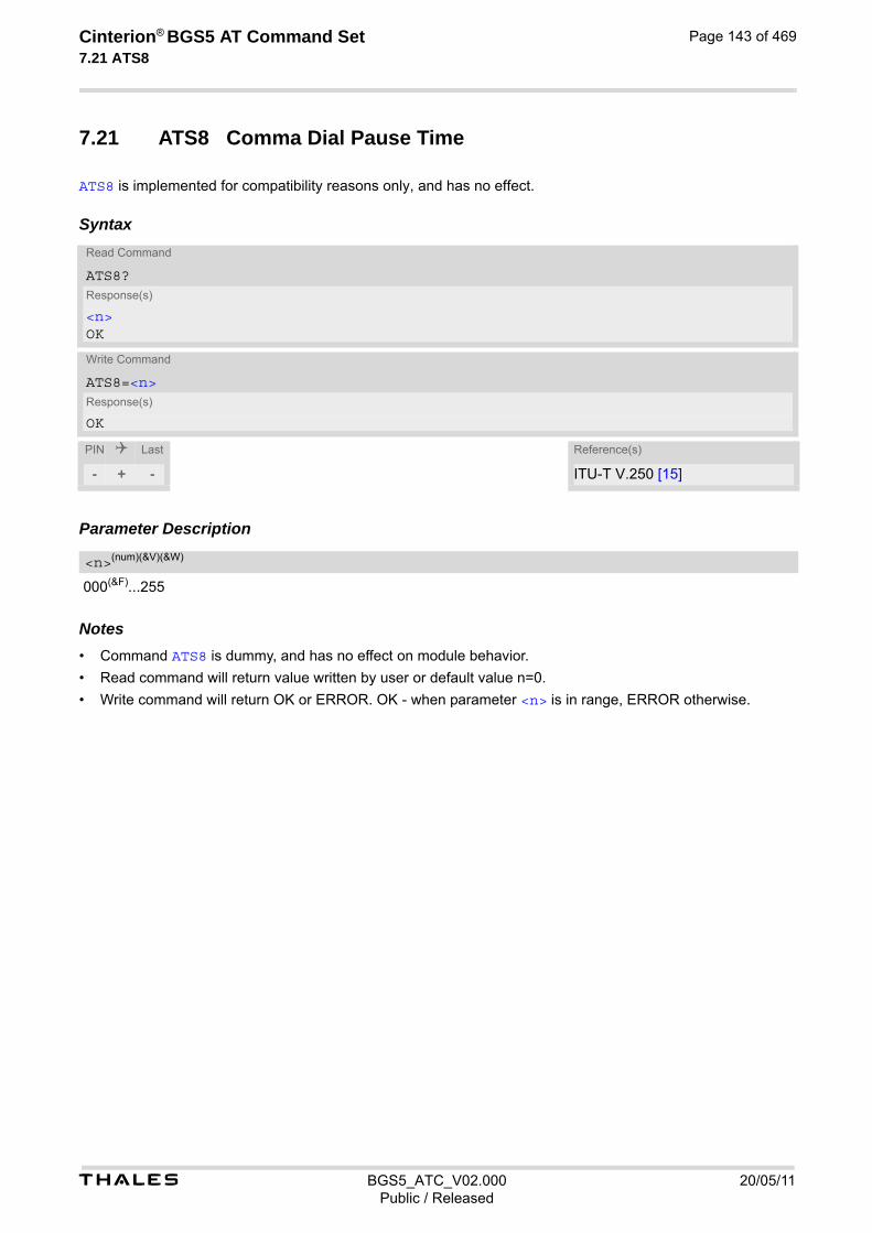
t BGS5_ATC_V02.000 20/05/11Public / Released
Cinterion® BGS5 AT Command Set 7.21 ATS8
Page 143 of 469
7.21 ATS8 Comma Dial Pause Time
ATS8 is implemented for compatibility reasons only, and has no effect.
Syntax
Parameter Description
000(&F)...255 Notes• Command ATS8 is dummy, and has no effect on module behavior.
• Read command will return value written by user or default value n=0.
• Write command will return OK or ERROR. OK - when parameter <n> is in range, ERROR otherwise.
Read Command
ATS8?Response(s)
<n>OK
Write Command
ATS8=<n>Response(s)
OK
PIN Last Reference(s)
- + - ITU-T V.250 [15]
<n>(num)(&V)(&W)
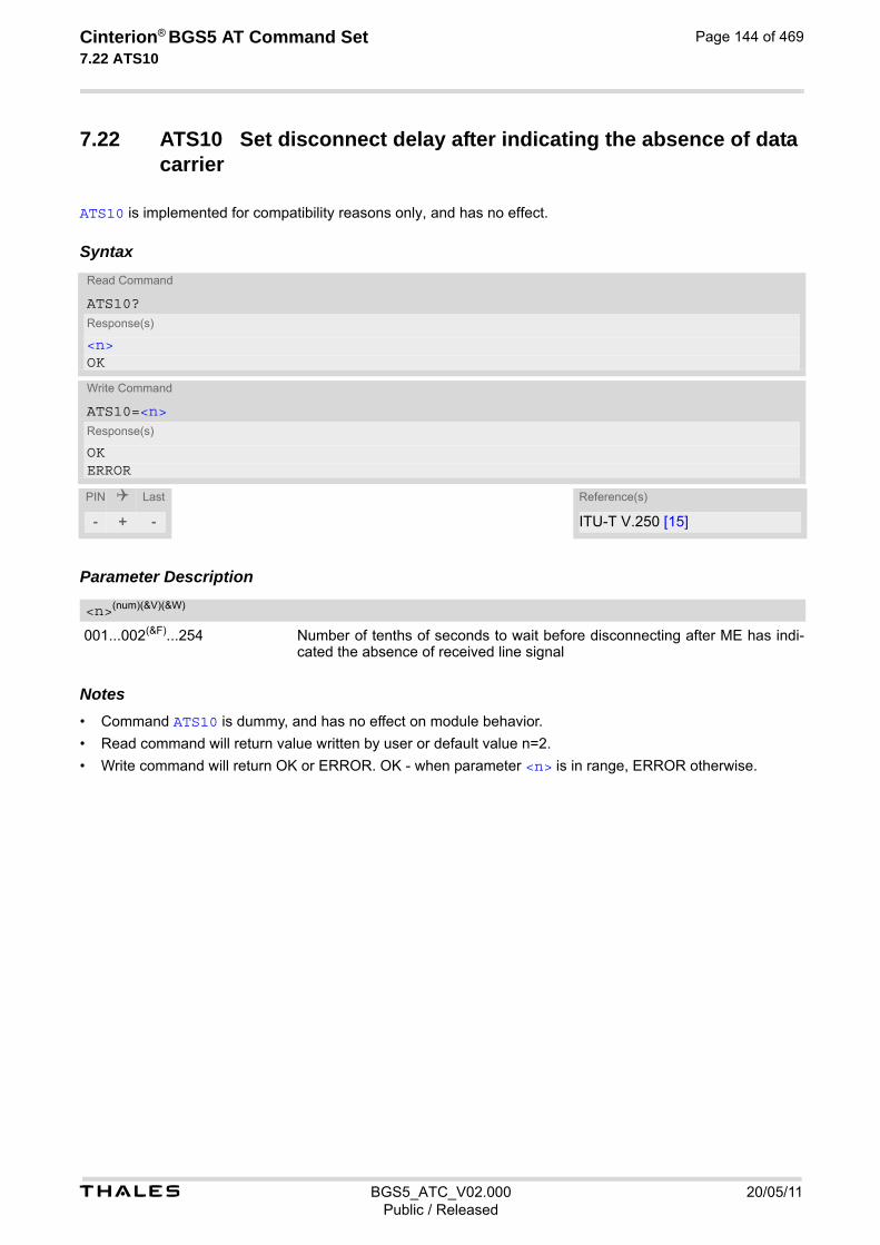
t BGS5_ATC_V02.000 20/05/11Public / Released
Cinterion® BGS5 AT Command Set 7.22 ATS10
Page 144 of 469
7.22 ATS10 Set disconnect delay after indicating the absence of data carrier
ATS10 is implemented for compatibility reasons only, and has no effect.
Syntax
Parameter Description
001...002(&F)...254 Number of tenths of seconds to wait before disconnecting after ME has indi-cated the absence of received line signal
Notes• Command ATS10 is dummy, and has no effect on module behavior.
• Read command will return value written by user or default value n=2.
• Write command will return OK or ERROR. OK - when parameter <n> is in range, ERROR otherwise.
Read Command
ATS10?Response(s)
<n>OK
Write Command
ATS10=<n>Response(s)
OKERROR
PIN Last Reference(s)
- + - ITU-T V.250 [15]
<n>(num)(&V)(&W)

Cinterion® BGS5 AT Command Set 8. Network Service Commands
t BGS5_ATC_V02.000 20/05/11Public / Released
Page 145 of 469
8. Network Service Commands
The AT Commands described in this chapter are related to various network services.
8.1 AT+COPN Read operator names
The AT+COPN command returns the list of operator names from the ME. Each operator code <numericn> that has an alphanumeric equivalent <alphan> in the ME memory is returned.
Syntax
Parameter Description
Operator in numeric format
Operator in long alphanumeric format
Test Command
AT+COPN=?Response(s)
OKERROR+CME ERROR: <err>
Exec Command
AT+COPNResponse(s)
+COPN: <numericn>, <alphan>[+COPN: ...]OKERROR+CME ERROR: <err>
PIN Last Reference(s)
+ + - 3GPP TS 27.007 [43]
<numericn>(str)
<alphan>(str)
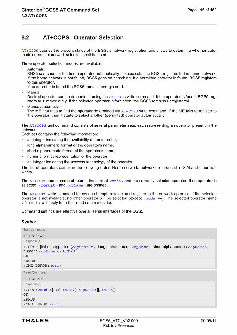
t BGS5_ATC_V02.000 20/05/11Public / Released
Cinterion® BGS5 AT Command Set 8.2 AT+COPS
Page 146 of 469
8.2 AT+COPS Operator Selection
AT+COPS queries the present status of the BGS5's network registration and allows to determine whether auto-matic or manual network selection shall be used. Three operator selection modes are available:
• Automatic BGS5 searches for the home operator automatically. If successful the BGS5 registers to the home network. If the home network is not found, BGS5 goes on searching. If a permitted operator is found, BGS5 registers to this operator. If no operator is found the BGS5 remains unregistered.
• Manual Desired operator can be determined using the AT+COPS write command. If the operator is found, BGS5 reg-isters to it immediately. If the selected operator is forbidden, the BGS5 remains unregistered.
• Manual/automatic The ME first tries to find the operator determined via AT+COPS write command. If the ME fails to register to this operator, then it starts to select another (permitted) operator automatically.
The AT+COPS test command consists of several parameter sets, each representing an operator present in the network. Each set contains the following information:
• an integer indicating the availability of the operator,
• long alphanumeric format of the operator's name,
• short alphanumeric format of the operator's name,
• numeric format representation of the operator.
• an integer indicating the acccess technology of the operator.
The list of operators comes in the following order: Home network, networks referenced in SIM and other net-works. The AT+COPS read command returns the current <mode> and the currently selected operator. If no operator is selected, <format> and <opName> are omitted. The AT+COPS write command forces an attempt to select and register to the network operator. If the selected operator is not available, no other operator will be selected (except <mode>=4). The selected operator name <format> will apply to further read commands, too. Command settings are effective over all serial interfaces of the BGS5.
SyntaxTest Command
AT+COPS=?Response(s)
+COPS: [list of supported (<opStatus>, long alphanumeric <opName>, short alphanumeric <opName>, numeric <opName>, <AcT>)s ]OKERROR+CME ERROR:<err>
Read Command
AT+COPS?Response(s)
+COPS:<mode>[, <format>[, <opName>][, <AcT>]]OKERROR+CME ERROR:<err>
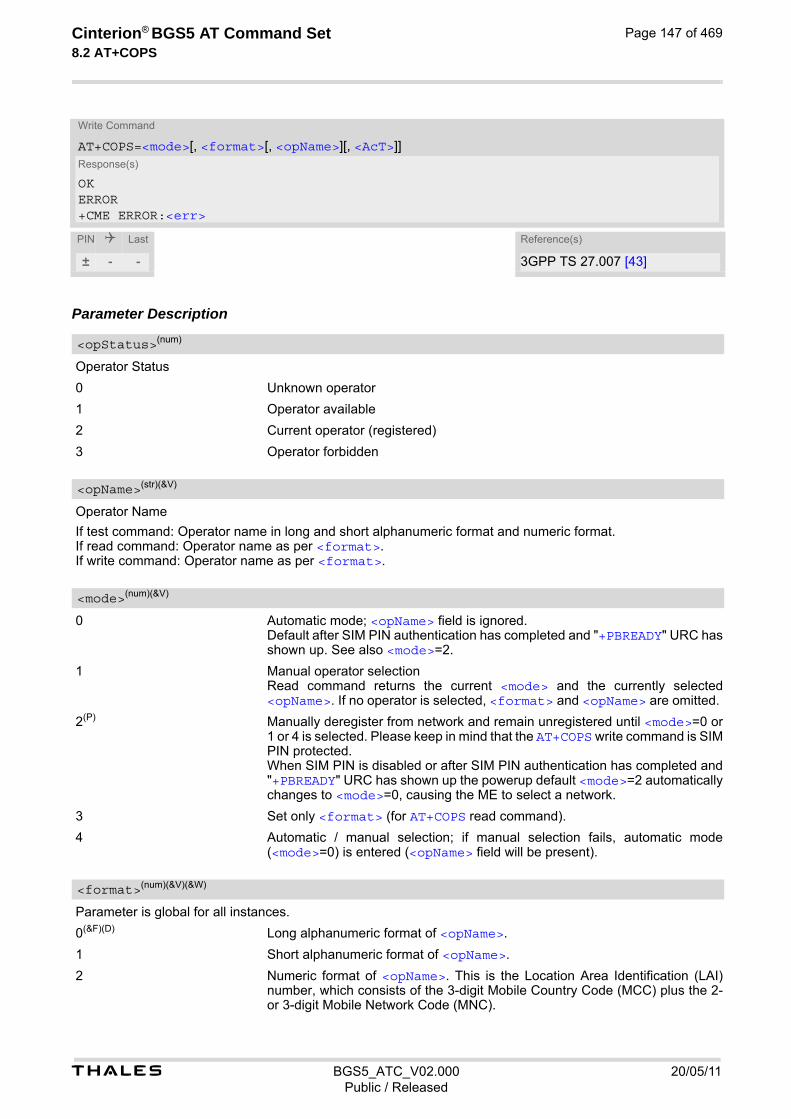
t BGS5_ATC_V02.000 20/05/11Public / Released
Cinterion® BGS5 AT Command Set 8.2 AT+COPS
Page 147 of 469
Parameter Description
Operator Status
0 Unknown operator
1 Operator available
2 Current operator (registered)
3 Operator forbidden
Operator Name
If test command: Operator name in long and short alphanumeric format and numeric format. If read command: Operator name as per <format>. If write command: Operator name as per <format>.
0 Automatic mode; <opName> field is ignored. Default after SIM PIN authentication has completed and "+PBREADY" URC has shown up. See also <mode>=2.
1 Manual operator selection Read command returns the current <mode> and the currently selected <opName>. If no operator is selected, <format> and <opName> are omitted.
2(P) Manually deregister from network and remain unregistered until <mode>=0 or 1 or 4 is selected. Please keep in mind that the AT+COPS write command is SIM PIN protected. When SIM PIN is disabled or after SIM PIN authentication has completed and "+PBREADY" URC has shown up the powerup default <mode>=2 automatically changes to <mode>=0, causing the ME to select a network.
3 Set only <format> (for AT+COPS read command).
4 Automatic / manual selection; if manual selection fails, automatic mode (<mode>=0) is entered (<opName> field will be present).
Parameter is global for all instances.
0(&F)(D) Long alphanumeric format of <opName>.
1 Short alphanumeric format of <opName>.
2 Numeric format of <opName>. This is the Location Area Identification (LAI) number, which consists of the 3-digit Mobile Country Code (MCC) plus the 2- or 3-digit Mobile Network Code (MNC).
Write Command
AT+COPS=<mode>[, <format>[, <opName>][, <AcT>]]Response(s)
OKERROR+CME ERROR:<err>
PIN Last Reference(s)
± - - 3GPP TS 27.007 [43]
<opStatus>(num)
<opName>(str)(&V)
<mode>(num)(&V)
<format>(num)(&V)(&W)
t BGS5_ATC_V02.000 20/05/11Public / Released
Cinterion® BGS5 AT Command Set 8.2 AT+COPS
Page 148 of 469
Radio Access Technology
Indicates the currently used radio access technology. See also AT+CREG for more detailed information on the used radio access technology.
0 GSM
<AcT>(num)(&V)

t BGS5_ATC_V02.000 20/05/11Public / Released
Cinterion® BGS5 AT Command Set 8.3 AT+CREG
Page 149 of 469
8.3 AT+CREG Network Registration Status
AT+CREG serves to monitor the BGS5's network registration status. Information can be reported by the AT+CREG? read command and by +CREG: URCs.
Syntax
Unsolicited Result Codes
URC 1
If <Mode>=1 and there is a change in the ME's network registration status:
+CREG: <regStatus>
URC 2
If <Mode>=2 and there is a change of the ME's network registration status or at least one of the additional network information elements:
+CREG: <regStatus>[, <netLac>, <netCellId>[, <AcT>]] Parameter Description
[0](&F)(D) Disables +CREG URC. Indication of network registration status +CREG: <regStatus> is possible by AT+CREG? read command.
1 Enables indication of network registration status +CREG: <regStatus> both by AT+CREG? read command and by +CREG URC.
2 Enables extended status information +CREG:<regStatus>[,<net-Lac>,<netCellId>[, <AcT>], both by read command AT+CREG? and by +CREG URC. Parameters <regStatus>, <netLac>, <netCellId>, <AcT> are only returned when ME is registered to network.
Test Command
AT+CREG=?Response(s)
+CREG: (list of supported<Mode>s)OK
Read Command
AT+CREG?Response(s)
+CREG: <Mode>, <regStatus>[, <netLac>, <netCellId>[, <AcT>]]OKERROR+CME ERROR: <err>
Write Command
AT+CREG=[<Mode>]Response(s)
OKERROR+CME ERROR: <err>
PIN Last Reference(s)
- + - 3GPP TS 27.007 [43]
<Mode>(num)(&V)(&W)

t BGS5_ATC_V02.000 20/05/11Public / Released
Cinterion® BGS5 AT Command Set 8.3 AT+CREG
Page 150 of 469
0 Not registered, ME is currently not searching for new operator
1 Registered to home network
2 Not registered, but ME is currently searching for a new operator.
3 Registration denied
4 Unknown (not used)
5 Registered, roaming ME is registered at a foreign network (national or international network)
Two byte location area code in hexadecimal format (e.g. "00C3" equals 195 in decimal).
Cell ID in hexadecimal format: - 16 bit for 2G
Radio access technology
“0“ GSM
“3“ GSM w/EGPRS
<regStatus>(num)(&V)
<netLac>(str)
<netCellId>(str)
<AcT>(str)
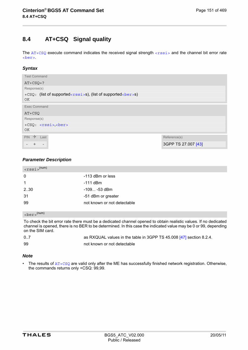
t BGS5_ATC_V02.000 20/05/11Public / Released
Cinterion® BGS5 AT Command Set 8.4 AT+CSQ
Page 151 of 469
8.4 AT+CSQ Signal quality
The AT+CSQ execute command indicates the received signal strength <rssi> and the channel bit error rate <ber>.
Syntax
Parameter Description
0 -113 dBm or less
1 -111 dBm
2..30 -109... -53 dBm
31 -51 dBm or greater
99 not known or not detectable
To check the bit error rate there must be a dedicated channel opened to obtain realistic values. If no dedicated channel is opened, there is no BER to be determined. In this case the indicated value may be 0 or 99, depending on the SIM card.
0..7 as RXQUAL values in the table in 3GPP TS 45.008 [47] section 8.2.4.
99 not known or not detectable Note• The results of AT+CSQ are valid only after the ME has successfully finished network registration. Otherwise,
the commands returns only +CSQ: 99,99.
Test Command
AT+CSQ=?Response(s)
+CSQ: (list of supported<rssi>s), (list of supported<ber>s)OK
Exec Command
AT+CSQResponse(s)
+CSQ: <rssi>,<ber>OK
PIN Last Reference(s)
- + - 3GPP TS 27.007 [43]
<rssi>(num)
<ber>(num)

t BGS5_ATC_V02.000 20/05/11Public / Released
Cinterion® BGS5 AT Command Set 8.5 AT+CPOL
Page 152 of 469
8.5 AT+CPOL Preferred Operator List
AT+CPOL read command queries the list of the preferred operators. AT+CPOL write command allows to edit the list of the preferred operators. The response of AT+CPOL read command also depends on the setting of AT+CPLS. If <index> is given but <operator> is left out, the entry is deleted.
Syntax
Parameter Description
The order number of the operator in the SIM preferred operator list.
0 Long alphanumeric format <operator>
1 Short alphanumeric format <operator>
2 Numeric format <operator>
The operator in the format specified in <format>.
Test Command
AT+CPOL=?Response(s)
+CPOL:(list of supported <index>s), (list of supported <format>s)OKERROR+CME ERROR: <err>
Read Command
AT+CPOL?Response(s)
+CPOL: <index>, <format>, <operator>[, <gsm>, <gsm_compact>, <utran>]+CPOL: ...OKERROR+CME ERROR: <err>
Write Command
AT+CPOL=[<index>][, <format>[[, <operator>][, <gsm>, <gsm_compact>, <utran>]]]Response(s)
OKERROR+CME ERROR: <err>
PIN Last Reference(s)
+ + - 3GPP TS 27.007 [43]
<index>(num)
<format>(num)
<operator>(str)

t BGS5_ATC_V02.000 20/05/11Public / Released
Cinterion® BGS5 AT Command Set 8.5 AT+CPOL
Page 153 of 469
0 AcT GSM disabled
1 AcT GSM enabled
0 AcT GSM Compact disabled
0 AcT UTRAN disabled
1 AcT UTRAN enabled Note• The Access Technology selection parameters <gsm>, <gsm_compact>, <utran> are required for SIM
cards or UICCs containing PLMN selector with Access Technology.
<gsm>(num)
<gsm_compact>(num)
<utran>(num)

t BGS5_ATC_V02.000 20/05/11Public / Released
Cinterion® BGS5 AT Command Set 8.6 AT+CPLS
Page 154 of 469
8.6 AT+CPLS Select Preferred Operator List
AT+CPLS is used to select a preferred PLMN list defined in Elementary Files of the SIM card or active application of the SIM. The setting takes effect for the AT+CPOL command.
Syntax
Parameter Description
0(P) User controlled PLMN with EFPLMNwAcT/EFPLMNsel If <plmn-selector> is omitted from the write command, the default value 0 is used instead.
1 Operator controlled PLMN selector with EFOPLMNwAcT
2 HPLMN selector with EFHPLMNwAcT
Test Command
AT+CPLS=?Response(s)
+CPLS:(list of SIM supported <plmn-selector>s) OK
Read Command
AT+CPLS?Response(s)
+CPLS: <plmn-selector>OKERROR+CME ERROR: <err>
Write Command
AT+CPLS=[<plmn-selector>]Response(s)
OKERROR+CME ERROR: <err>
PIN Last Reference(s)
+ - - 3GPP TS 27.007 [43]
<plmn-selector>(num)
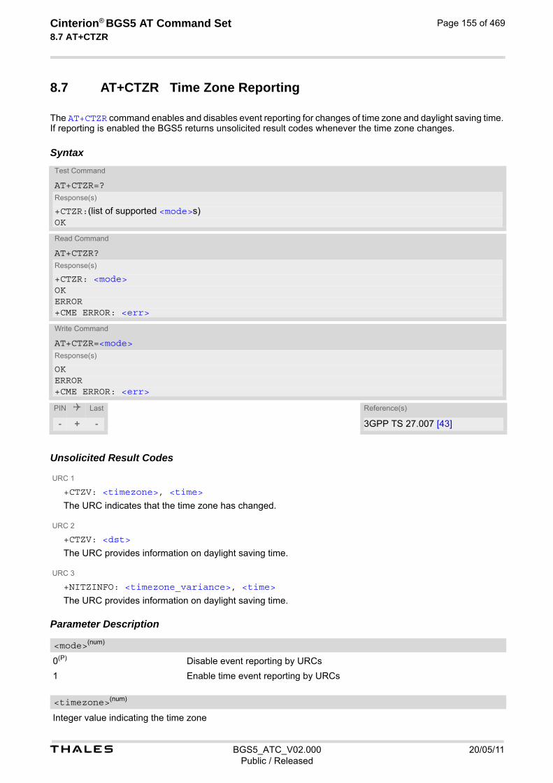
t BGS5_ATC_V02.000 20/05/11Public / Released
Cinterion® BGS5 AT Command Set 8.7 AT+CTZR
Page 155 of 469
8.7 AT+CTZR Time Zone Reporting
The AT+CTZR command enables and disables event reporting for changes of time zone and daylight saving time. If reporting is enabled the BGS5 returns unsolicited result codes whenever the time zone changes.
Syntax
Unsolicited Result Codes
URC 1
+CTZV: <timezone>, <time>
The URC indicates that the time zone has changed.
URC 2
+CTZV: <dst>
The URC provides information on daylight saving time.
URC 3
+NITZINFO: <timezone_variance>, <time>
The URC provides information on daylight saving time. Parameter Description
0(P) Disable event reporting by URCs
1 Enable time event reporting by URCs
Integer value indicating the time zone
Test Command
AT+CTZR=?Response(s)
+CTZR:(list of supported <mode>s) OK
Read Command
AT+CTZR?Response(s)
+CTZR: <mode>OKERROR+CME ERROR: <err>
Write Command
AT+CTZR=<mode>Response(s)
OKERROR+CME ERROR: <err>
PIN Last Reference(s)
- + - 3GPP TS 27.007 [43]
<mode>(num)
<timezone>(num)

t BGS5_ATC_V02.000 20/05/11Public / Released
Cinterion® BGS5 AT Command Set 8.7 AT+CTZR
Page 156 of 469
Time in format "yy/MM/dd,hh:mms", wherein characters indicates year, month, day, hour, minutes, seconds.
Parameter indicates daylight saving time as follows:
0 No adjustment for daylight daving time
1 +1 hour adjustment for daylight saving time
2 +2 hour adjustment for daylight saving time
Timezone variance
Time in format "GMT+HH:MM" or "GMT-HH:MM", e.g. "GMT+5:30".
<time>(str)
<dst>(num)
<timezone_variance>(str)

t BGS5_ATC_V02.000 20/05/11Public / Released
Cinterion® BGS5 AT Command Set 8.8 AT+CTZU
Page 157 of 469
8.8 AT+CTZU Automatic Time Zone Update
The AT+CTZU command enables and disables automatic time zone update via NITZ. When AT+CTZU is set to 1, the Real Time Clock (RTC) on the ME is updated with the network time every time when the ME receives a NITZ message. Any changes to the RTC using the command AT+CCLK will be wiped out by the network time when a new NITZ message is received. In addition, AT+CTZR can be used to activate indicators reporting time zone information change. When AT+CTZU is set to 0, AT+CCLK can be used to set the RTC. The newly set time will not be overwritten by the network time. The AT^SIND command can also be used to get NITZ information, for details see "nitz" indicator. Unlike AT+CTZU, AT^SIND settings have no effect for the RTC.
Syntax
Parameter Description
0(P) Disable automatic time zone update via NITZ
1 Enable automatic time zone update via NITZ.
Test Command
AT+CTZU=?Response(s)
+CTZU:(list of supported <mode>s) OK
Read Command
AT+CTZU?Response(s)
+CTZU: <mode>OKERROR+CME ERROR: <err>
Write Command
AT+CTZU=<mode>Response(s)
OKERROR+CME ERROR: <err>
PIN Last Reference(s)
- + - 3GPP TS 27.007 [43]
<mode>(num)

t BGS5_ATC_V02.000 20/05/11Public / Released
Cinterion® BGS5 AT Command Set 8.9 AT^SMONP
Page 158 of 469
8.9 AT^SMONP Display Neighbor Cell Information
The AT^SMONP command displays information on neighboring cells.
Syntax
Note• During a CS connection or in Airplane mode the response is empty and displayed as follows:
"----,--,----,---,---,-,-,--,--,----,----" For other responses see Section 8.9.1, AT^SMONP (Enhanced) Responses.
8.9.1 AT^SMONP (Enhanced) Responses
Responses of the AT^SMONP exec command. Possible enhanced responses (AT^SMONP=255) are given between <...>:
Test Command
AT^SMONP=?Response(s)
OK
Exec Command
AT^SMONPResponse(s)
See: Section 8.9.1, AT^SMONP (Enhanced) ResponsesOKERROR+CME ERROR: <err>
Write Command
AT^SMONP=255 Response(s)
See: Section 8.9.1, AT^SMONP (Enhanced) ResponsesOKERROR+CME ERROR: <err>
PIN Last
± - -
Syntax:2G:ARFCN1,RSSI1,Rxlev1,MCC1,MNC1,NCC1,BCC1,C11,C21,LAC1,CI1<,C311><,C321>ARFCN2,RSSI2,Rxlev2,MCC2,MNC2,NCC2,BCC2,C12,C22,LAC2,CI2<,C312><,C322>...ARFCNn,RSSIn,Rxlevn,MCCn,MNCn,NCCn,BCCn,C1n,C2n,LACn,CIn<,C31n><,C32n>
Example:2G:653,26,-84,262,07,3,0,22,22,0141,3B2F,0,0660,20,-90,262,07,3,3,16,16,0143,83B9,0,0
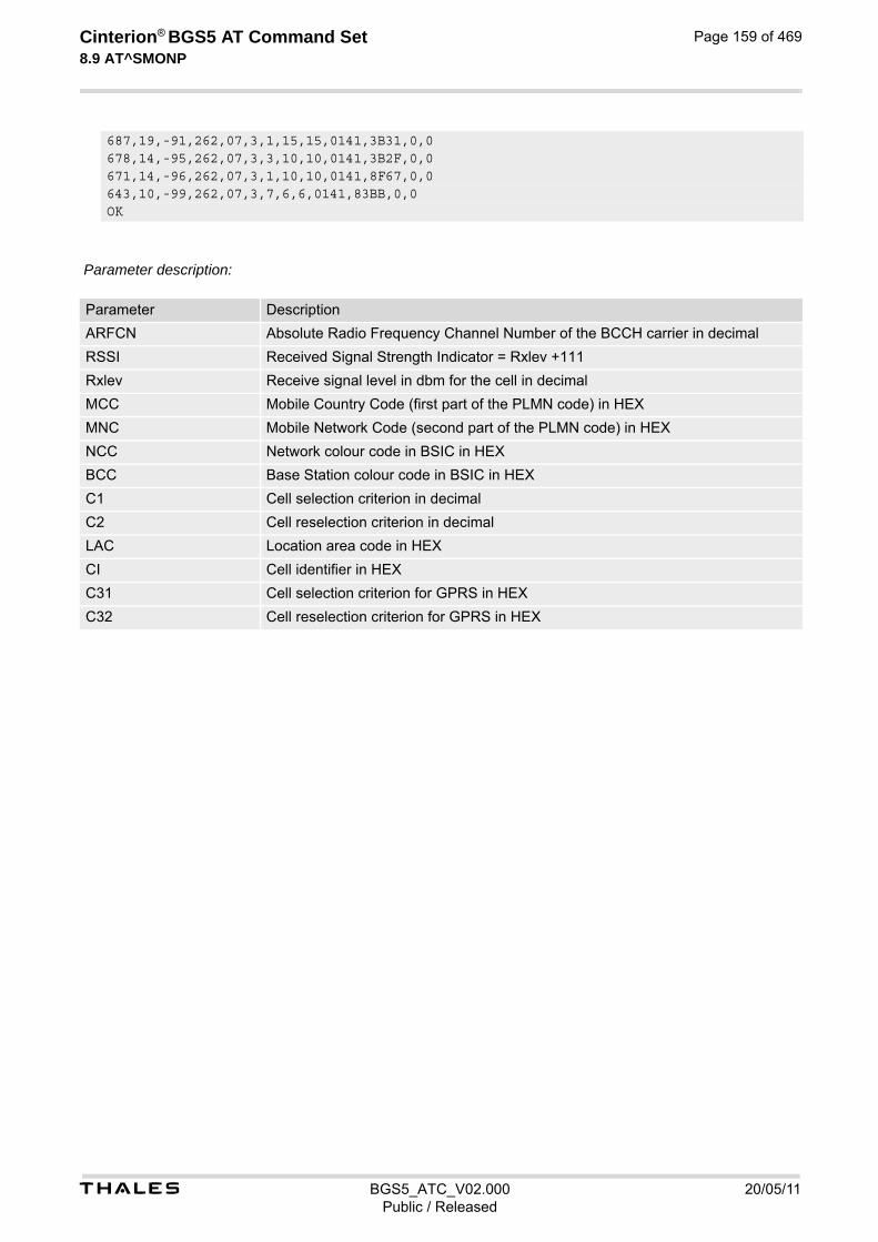
t BGS5_ATC_V02.000 20/05/11Public / Released
Cinterion® BGS5 AT Command Set 8.9 AT^SMONP
Page 159 of 469
Parameter description:
687,19,-91,262,07,3,1,15,15,0141,3B31,0,0678,14,-95,262,07,3,3,10,10,0141,3B2F,0,0671,14,-96,262,07,3,1,10,10,0141,8F67,0,0643,10,-99,262,07,3,7,6,6,0141,83BB,0,0OK
Parameter Description
ARFCN Absolute Radio Frequency Channel Number of the BCCH carrier in decimal
RSSI Received Signal Strength Indicator = Rxlev +111
Rxlev Receive signal level in dbm for the cell in decimal
MCC Mobile Country Code (first part of the PLMN code) in HEX
MNC Mobile Network Code (second part of the PLMN code) in HEX
NCC Network colour code in BSIC in HEX
BCC Base Station colour code in BSIC in HEX
C1 Cell selection criterion in decimal
C2 Cell reselection criterion in decimal
LAC Location area code in HEX
CI Cell identifier in HEX
C31 Cell selection criterion for GPRS in HEX
C32 Cell reselection criterion for GPRS in HEX
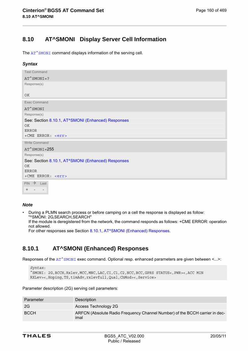
t BGS5_ATC_V02.000 20/05/11Public / Released
Cinterion® BGS5 AT Command Set 8.10 AT^SMONI
Page 160 of 469
8.10 AT^SMONI Display Server Cell Information
The AT^SMONI command displays information of the serving cell.
Syntax
Note• During a PLMN search process or before camping on a cell the response is displayed as follow:
"^SMONI: 2G,SEARCH,SEARCH" If the module is deregistered from the network, the command responds as follows: +CME ERROR: operation not allowed. For other responses see Section 8.10.1, AT^SMONI (Enhanced) Responses.
8.10.1 AT^SMONI (Enhanced) Responses
Responses of the AT^SMONI exec command. Optional resp. enhanced parameters are given between <...>:
Parameter description (2G) serving cell parameters:
Test Command
AT^SMONI=?Response(s)
OK
Exec Command
AT^SMONIResponse(s)
See: Section 8.10.1, AT^SMONI (Enhanced) ResponsesOKERROR+CME ERROR: <err>
Write Command
AT^SMONI=255 Response(s)
See: Section 8.10.1, AT^SMONI (Enhanced) ResponsesOKERROR+CME ERROR: <err>
PIN Last
+ - -
Syntax:^SMONI: 2G,BCCH,Rxlev,MCC,MNC,LAC,CI,C1,C2,NCC,BCC,GPRS STATUS<,PWR><,ACC MIN RXLev><,Hoping,TS,timAdv,rxlevfull,Qual,ChMod><,Service>
Parameter Description
2G Access Technology 2G
BCCH ARFCN (Absolute Radio Frequency Channel Number) of the BCCH carrier in dec-imal

t BGS5_ATC_V02.000 20/05/11Public / Released
Cinterion® BGS5 AT Command Set 8.10 AT^SMONI
Page 161 of 469
Parameter desription (2G) dedicated channel parameters:
8.10.2 Service states
Depending on the service state, an additional textual output is generated (refer also to the response examples):
• 'SEARCH' (Searching) - The MS is searching, but could not (yet) find a suitable cell. This output appears after restart of the MS or after loss of coverage.
• 'NOCONN' (No connection) - The MS is camping on a cell and registered to the network. The service state is 'idle', i.e. there is no connection established or a dedicated channel in use.
• 'LIMSRV' (Limited Service) - The MS is camping on a cell but not registered to the network. Only emergency calls are allowed. The MS enters this state, for example, when
- no SIM card is inserted, or PIN has not been given,
Rxlev Receiving level of the BCCH carrier in dBm in decimal
MCC Mobile Country Code (first part of the PLMN code) in HEX
MNC Mobile Network Code (second part of the PLMN code) in HEX
LAC Location Area Code in HEX
CI Cell ID in HEX
C1 Cell selection criterion in decimal
C2 Cell reselection criterion in decimal
NCC Network colour code in BSIC in HEX
BCC Base Station colour code in BSIC in HEX
GPRS GPRS status. Possible characters: "G" - GPRS support, "E" - EDGE support, "-" - GSM support
PWR Maximal power level used on RACH channel in dBm
ACC MIN RXLev Minimal receiving level (in dBm) to allow registration
Service See Section 8.10.2, Service states.
Parameter Description
Hoping Either "h" - hopping frequencies exist, "<number>" - ARFCN (Absolute Radio Fre-quency Channel Number) of the BCCH carrier or "----" - not a valid ARFCN
TS Timeslot number
timAdv Timing advance in bits
rxlevfull Receiving level of the traffic channel carrier in dBm
Qual Receiving quality (0-7)
ChMod Channel mode (--: Signalling, "S_FR": GSM speech full rate version 1: GSM FR "S_EFR": GSM speech full rate version 2: GSM EFR "A_FR": GSM speech full rate version 3: FR AMR "A_HR": GSM speech half rate version 3: HR AMR "A_OFR_WB": GSM speech full rate version 4: OFR AMR-WB "A_FR_WB": GSM speech full rate version 5: FR AMR-WB "A_OFR": GSM speech full rate version 3: FR AMR "A_FR_WB": GSM speech full rate version 5: FR AMR-WB "A_OHR_WB": GSM speech half rate version 4: OHR AMR-WB "A_OHR": GSM speech half rate version 6: OHR AMR "DATA": data service type "--": control signal format "???":MODE_SPEECH_H_V2
Parameter Description

t BGS5_ATC_V02.000 20/05/11Public / Released
Cinterion® BGS5 AT Command Set 8.10 AT^SMONI
Page 162 of 469
- neither Home PLMN nor any other allowed PLMN are found,
- registration request was not answered or denied by the network (use command AT+CREG to query the reg-istration status),
- authentication failed.
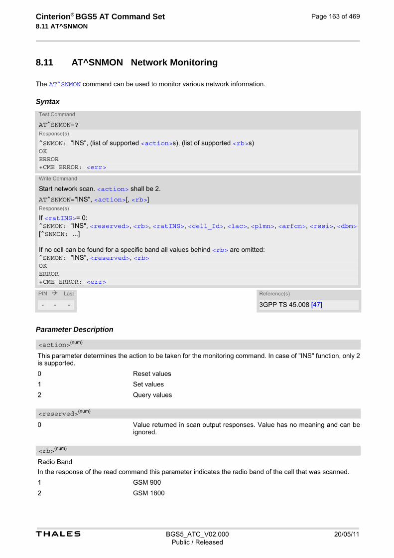
t BGS5_ATC_V02.000 20/05/11Public / Released
Cinterion® BGS5 AT Command Set 8.11 AT^SNMON
Page 163 of 469
8.11 AT^SNMON Network Monitoring
The AT^SNMON command can be used to monitor various network information.
Syntax
Parameter Description
This parameter determines the action to be taken for the monitoring command. In case of "INS" function, only 2 is supported.
0 Reset values
1 Set values
2 Query values
0 Value returned in scan output responses. Value has no meaning and can be ignored.
Radio Band
In the response of the read command this parameter indicates the radio band of the cell that was scanned.
1 GSM 900
2 GSM 1800
Test Command
AT^SNMON=?Response(s)
^SNMON: "INS", (list of supported <action>s), (list of supported <rb>s)OKERROR+CME ERROR: <err>
Write Command
Start network scan. <action> shall be 2.
AT^SNMON="INS", <action>[, <rb>]Response(s)
If <ratINS>= 0:^SNMON: "INS", <reserved>, <rb>, <ratINS>, <cell_Id>, <lac>, <plmn>, <arfcn>, <rssi>, <dbm>[^SNMON: ...]
If no cell can be found for a specific band all values behind <rb> are omitted:^SNMON: "INS", <reserved>, <rb>OKERROR+CME ERROR: <err>
PIN Last Reference(s)
- - - 3GPP TS 45.008 [47]
<action>(num)
<reserved>(num)
<rb>(num)

t BGS5_ATC_V02.000 20/05/11Public / Released
Cinterion® BGS5 AT Command Set 8.11 AT^SNMON
Page 164 of 469
4 GSM 850
8 GSM 1900
Radio Access Technology for subcommand INS
0 GSM
PLMN code
Signal Strength in dBm
Absolute Radio Frequency Channel Number of the BCCH carrier.
Received signal level of the BCCH carrier. The indicated value is composed of the measured value in dBm plus an offset. This is in accordance with a formula specified in 3GPP TS 45.008 [47]
Location Area Code
Two byte location area code in hexadecimal format (e.g. "00C1" equals 193 in decimal) of the cell that was scanned.
Cell ID (16 bit for GSM), Notes• The AT^SNMON="INS " command can be used even if no SIM is present or no SIM-PIN was entered.
• The AT^SNMON="INS " command depends on the registration state. A complete network scan is only possible if the module is not registered. To perform a complete scan it is recommended to deregister manually from the network.
• The AT^SNMON="INS " command may be aborted internally by any other network related activity that inter-feres with the network scan.
• The time required for a network scan depends not only on the number of radio bands to be scanned, but also on ripple and existing ghost peaks on the scanned radio bands.
<ratINS>(num)
<plmn>(str)
<dbm>(str)
<arfcn>(num)
<rssi>(num)
<lac>(str)
<cell_Id>(str)
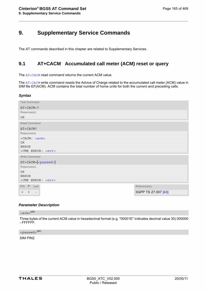
Cinterion® BGS5 AT Command Set 9. Supplementary Service Commands
t BGS5_ATC_V02.000 20/05/11Public / Released
Page 165 of 469
9. Supplementary Service Commands
The AT commands described in this chapter are related to Supplementary Services.
9.1 AT+CACM Accumulated call meter (ACM) reset or query
The AT+CACM read command returns the current ACM value. The AT+CACM write command resets the Advice of Charge related to the accumulated call meter (ACM) value in SIM file EF(ACM). ACM contains the total number of home units for both the current and preceding calls.
Syntax
Parameter Description
Three bytes of the current ACM value in hexadecimal format (e.g. "00001E" indicates decimal value 30) 000000 - FFFFFF.
SIM PIN2
Test Command
AT+CACM=?Response(s)
OK
Read Command
AT+CACM?Response(s)
+CACM: <acm>OKERROR+CME ERROR: <err>
Write Command
AT+CACM=[<passwd>]Response(s)
OKERROR+CME ERROR: <err>
PIN Last Reference(s)
+ + - 3GPP TS 27.007 [43]
<acm>(str)
<passwd>(str)

t BGS5_ATC_V02.000 20/05/11Public / Released
Cinterion® BGS5 AT Command Set 9.2 AT+CAMM
Page 166 of 469
9.2 AT+CAMM Accumulated call meter maximum (ACMmax) set or query
The AT+CAMM read command returns the current ACMmax value. The AT+CAMM write command sets the Advice of Charge related to the accumulated call meter maximum value in SIM file EF (ACMmax). ACMmax contains the maximum number of home units allowed to be consumed by the subscriber.
Syntax
Parameter Description
Three bytes of the max. ACM value in hexadecimal format (e.g. "00001E" indicates decimal value 30) 000000 disable ACMmax feature 000001-FFFFFF.
SIM PIN2
Test Command
AT+CAMM=?Response(s)
OK
Read Command
AT+CAMM?Response(s)
+CAMM: <acmmax>OKERROR+CME ERROR: <err>
Write Command
AT+CAMM=<acmmax>[, <passwd>]Response(s)
OKERROR+CME ERROR: <err>
PIN Last Reference(s)
+ + - 3GPP TS 27.007 [43]
<acmmax>(str)
<passwd>(str)
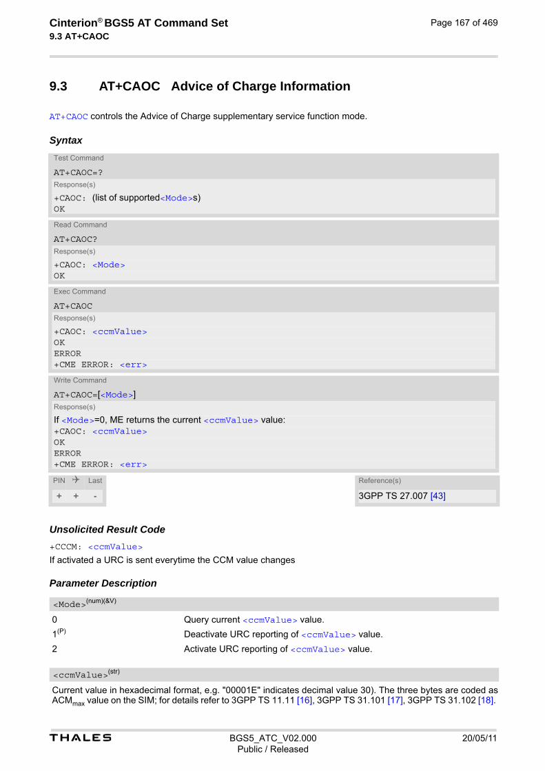
t BGS5_ATC_V02.000 20/05/11Public / Released
Cinterion® BGS5 AT Command Set 9.3 AT+CAOC
Page 167 of 469
9.3 AT+CAOC Advice of Charge Information
AT+CAOC controls the Advice of Charge supplementary service function mode.
Syntax
Unsolicited Result Code+CCCM: <ccmValue>
If activated a URC is sent everytime the CCM value changes Parameter Description
0 Query current <ccmValue> value.
1(P) Deactivate URC reporting of <ccmValue> value.
2 Activate URC reporting of <ccmValue> value.
Current value in hexadecimal format, e.g. "00001E" indicates decimal value 30). The three bytes are coded as ACMmax value on the SIM; for details refer to 3GPP TS 11.11 [16], 3GPP TS 31.101 [17], 3GPP TS 31.102 [18].
Test Command
AT+CAOC=?Response(s)
+CAOC: (list of supported<Mode>s)OK
Read Command
AT+CAOC?Response(s)
+CAOC: <Mode>OK
Exec Command
AT+CAOCResponse(s)
+CAOC: <ccmValue> OKERROR+CME ERROR: <err>
Write Command
AT+CAOC=[<Mode>]Response(s)
If <Mode>=0, ME returns the current <ccmValue> value: +CAOC: <ccmValue> OKERROR+CME ERROR: <err>
PIN Last Reference(s)
+ + - 3GPP TS 27.007 [43]
<Mode>(num)(&V)
<ccmValue>(str)

t BGS5_ATC_V02.000 20/05/11Public / Released
Cinterion® BGS5 AT Command Set 9.4 AT+CCUG
Page 168 of 469
9.4 AT+CCUG Closed User Group
The AT+CCUG write command serves to activate or deactivate the explicit CUG invocation, to set the desired index, and to specify if Preferential Group or Outgoing Access shall be suppressed. The AT+CCUG read command returns if the Explicit CUG invocation is activated (in parameter <n>), which CUG <index> is chosen, and if Preferential Group or Outgoing Access is suppressed (in parameter <info>).
Syntax
Parameter Description
Explicit CUG invocation options
0(P) Deactivate explicit CUG invocation
1 Activate explicit CUG invocation
0(P)...9 Explicit selection of CUG index
10 No index (preferred CUG taken from subscriber data)
State of the call
0(P) No information
Test Command
AT+CCUG=?Response(s)
list of supported <n>, range of supported <index>, range of supported <info>OKERROR+CME ERROR: <err>
Read Command
AT+CCUG?Response(s)
+CCUG:<n>, <index>, <info>OKERROR+CME ERROR: <err>
Write Command
AT+CCUG=[[<n>][, <index>][, <info>]]Response(s)
OKERROR+CME ERROR: <err>
PIN Last Reference(s)
+ + - 3GPP TS 27.007 [43], 3GPP TS 22.085 [30], 3GPP TS 24.085
<n>(num)
<index>(num)
<info>(num)
t BGS5_ATC_V02.000 20/05/11Public / Released
Cinterion® BGS5 AT Command Set 9.4 AT+CCUG
Page 169 of 469
1 Suppress outgoing access
2 Suppress preferential CUG
3 Suppress preferential CUG and Outgoing Access. Notes• The active settings for omitted parameters are retained without changes.
• Explicit CUG invocation means that at each call setup, CUG information is added to the called number.
• When starting a call with ATD, Parameter 'G' or 'g' of command ATD will have no effect if the option selected for this single call is identical to the option already selected with AT+CCUG.
• Current settings are saved in the ME automatically.
• ATZ or AT&F do not influence the current settings.
• Some combinations of parameters may lead to rejection of CUG calls by the network. For more information, please consult 3GPP TS 24.085.

t BGS5_ATC_V02.000 20/05/11Public / Released
Cinterion® BGS5 AT Command Set 9.5 AT+CCFC
Page 170 of 469
9.5 AT+CCFC Call forwarding number and conditions control
AT+CCFC controls the call forwarding supplementary service. Registration, erasure, activation, deactivation and status query are supported.
Syntax
Parameter Description
Reason for call forwarding
0 Unconditional
1 Mobile busy
2 No reply
3 Not reachable
4 All call forwarding (includes reasons 0, 1, 2 and 3)
5 all conditional call forwarding (includes reasons 1, 2 and 3)
Network operation to be performed for Supplementary service "call forwarding"
0 Disable call forwarding (disable service)
1 Enable call forwarding (enable service)
2 Query status of call forwarding (query service status)
Test Command
AT+CCFC=?Response(s)
+CCFC:(list/range of supported <reason>s) OK
Write Command
AT+CCFC=<reason>, <mode>[, <number>[, <type>[, <class>[, <time>]]]]Response(s)
If <mode> is not equal 2 and command successful: OKIf <mode>= 2, <reason> is not equal 2 and command successful: +CCFC: <status>, <class>[, <number>, <type>]OKIf <mode>= 2, <reason>= 2 and command successful: +CCFC: <status>, <class>[, <number>, <type>[, <subaddress>, <satype>[, <time>]]]OKIf error is related to ME functionality ERROR+CME ERROR: <err>
PIN Last Reference(s)
+ ± - 3GPP TS 27.007 [43], 3GPP TS 22.004 [23], 3GPP TS 22.082 [28], 3GPP TS 24.082
<reason>(num)
<mode>(num)

t BGS5_ATC_V02.000 20/05/11Public / Released
Cinterion® BGS5 AT Command Set 9.5 AT+CCFC
Page 171 of 469
3 Register <number> and activate Call forwarding (register service)
4 Erase <number> and deactivate call forwarding (erase service)
String type phone number of forwarding address in format specified by <type>. If you select <mode>= 3, the phone <number> will be registered in the network. This allows you to disable / enable CF to the same destination without the need to enter the phone number once again. Depending on the services offered by the provider the registration may be mandatory before CF can be used. The number remains registered in the network until you register another number or erase it using <mode> = 4.
Type of address octet
145 Dialing string <number> includes international access code character '+'
129 Otherwise
Integer or sum of integers each representing a class of information, i.e. a bearer service, telecommunication ser-vice or bearer service group as defined in 3GPP TS 22.004 [23]
1 Voice
2 Data <class> 2 (data) comprises all those <class> values between 16 and 128, that are supported both by the network and the MS. This means, a setting made for <class> 2 applies to all remaining data classes (if supported). In addition, you can assign a different setting to a specific class. For example, you can activate Call Forwarding for all data classes, but deactivate it for a specific data class.
4 Fax (only for compatibility reasons, not supported by BGS5)
8 SMS
16 Data circuit sync
32 Data circuit async
64 Dedicated packet access
128 Dedicated PAD access
1...[7]...255 combination of some of the above classes. For example, the default setting 7 represents the sum of the integers 1, 2 and 4 for voice, data and fax (fax only for compatibilty reasons). The value 255 covers all classes. If the <class> parameter is omitted, the default value 7 is used.
Only for compatibility reasons, not supported by BGS5
Only for compatibility reasons, not supported by BGS5
5...[20]...30 Time to wait before call is forwarded, rounded to a multiple of 5 sec. (only for <reason>=no reply)
0 Call Forwarding not active
1 Call Forwarding active
<number>(str)
<type>(num)
<class>(num)
<subaddress>(str)
<satype>(num)
<time>(num)
<status>(num)

t BGS5_ATC_V02.000 20/05/11Public / Released
Cinterion® BGS5 AT Command Set 9.5 AT+CCFC
Page 172 of 469
Notes• You can register, disable, enable and erase <reason> 4 and 5 as described above. However, querying the
status of <reason> 4 and 5 with AT+CCFC will result in an error ("+CME ERROR: operation not supported"). As an alternative, you may use the ATD command followed by *'# codes to check the status of these two rea-sons. See Star-Hash (*#) Network Commands for a complete list of *# GSM codes.
• Most networks will not permit registration of new parameters for conditional call forwarding (reasons 1,2,3,5) while unconditional call forwarding is enabled.
• The AT+CCFC command offers a broad range of call forwarding options according to the GSM specifications. However, when you attempt to set a call forwarding option which is not provisioned or not yet subscribed to, the setting will not take effect regardless of the response returned. The responses in these cases vary with the network (for example "OK", "Operation not allowed", "Operation not supported" etc.). To make sure check the call forwarding status with <mode>=2.
• Some networks may choose to have certain call forwarding condtions permanently enabled (e.g. forwarding to a mailbox if the mobile is not reachable). In this case, erasure or deactivation of call forwarding for these conditions will not be successful, even if the CCFC request is answered with response "OK".
• The command has been implemented with the full set of <class> parameters according to 3GPP TS 27.007 [43]. For actual applicability of SS "call forwarding" to a specific service or service group (a specific <class> value) please consult table A.1 of 3GPP TS 22.004 [23].
• There is currently no release of 3GPP TS 22.004 [23], in which the "Call Forwarding" Supplementary Service is defined as applicable to SMS services.

t BGS5_ATC_V02.000 20/05/11Public / Released
Cinterion® BGS5 AT Command Set 9.6 AT+CCWA
Page 173 of 469
9.6 AT+CCWA Call Waiting
The AT+CCWA write command controls the "Call Waiting" supplementary service according to 3GPP TS 22.083 [29]. Activation, deactivation and status query are supported. The read command returns the current value of <n>.
Syntax
Unsolicited Result CodeIndication of a call that is currently waiting and can be accepted.
+CCWA: <calling number>, <type of number>, <class>, , <CLI validity>
If <n>=1 and the call waiting supplementary service is enabled in the network, URC "+CCWA" indicates a waiting call to the TE. It appears while the waiting call is still ringing. Parameter Description
0 Disable display of "+CCWA" URC
1 Enable display of "+CCWA" URC
Test Command
AT+CCWA=?Response(s)
+CCWA:(list of supported <n>s) OK
Read Command
AT+CCWA?Response(s)
+CCWA:<n> OK
Write Command
AT+CCWA=[[<n>][, <mode>][, <class>]]Response(s)
If <mode> is not equal 2 and command successful: OKIf <mode>= 2 and command successful: +CCWA: <status>, <class>[+CCWA: <status>, <class>][+CCWA: ...]OKIf error is related to ME functionality +CME ERROR: <err>
PIN Last Reference(s)
+ - - 3GPP TS 27.007 [43], 3GPP TS 22.004 [23], 3GPP TS 22.083 [29], 3GPP TS 24.083
<n>(num)

t BGS5_ATC_V02.000 20/05/11Public / Released
Cinterion® BGS5 AT Command Set 9.6 AT+CCWA
Page 174 of 469
Network operation to be performed for Supplementary service call waiting
0 Disable call waiting (disable service)
1 Enable call waiting (enable service)
2 Query status of call waiting (query service status)
Integer or sum of integers each representing a class of information, i.e. a bearer service, telecommunication ser-vice or bearer service group as defined in 3GPP TS 22.004 [23]. In the write command, parameter <class> specifies the class of the active call during which an incoming call of any class is to be regarded as a waiting call. In URC "+CCWA: <calling number>, <type of number>, <class>, , <CLI validity>", parameter <class> specifies the class of the waiting call.
1 Voice
2 Data <class> 2 (data) comprises all those <class> values between 16 and 128, that are supported both by the network and the MS. This means, a setting made for <class> 2 applies to all remaining data classes (if supported). In addition, you can assign a different setting to a specific class. For example, you can activate call waiting for all data classes, but deactivate it for a specific data class.
4 Fax (only for compatibility reasons, not supported by BGS5)
[7] Voice, data and fax (1+2+4)
8 SMS
16 Data circuit sync
32 Data circuit async
64 Dedicated packet access
128 Dedicated PAD access
1...[7]...255 Combination of some of the above classes. For example, the default setting 7 represents the sum of the integers 1, 2 and 4 for voice, data and fax (fax only for compatibilty reasons). If parameter "class"is omitted, the default value 7 is used.
0 Call waiting service is not active
1 Call waiting service is active
Phone number of waiting caller in the format specified by parameter <type of number>.
Type of address octet in integer format (refer to 3GPP TS 24.008 [38] subclause 10.5.4.7)
145 <calling number> includes international access code character '+'
128 Number restricted
129 Otherwise
0 CLI valid
<mode>(num)
<class>(num)
<status>(num)
<calling number>(str)
<type of number>(num)
<CLI validity>(num)
t BGS5_ATC_V02.000 20/05/11Public / Released
Cinterion® BGS5 AT Command Set 9.6 AT+CCWA
Page 175 of 469
1 CLI has been withheld
2 CLI is not available Notes• With the AT+CHLD command, it is possible to establish a multiparty call or to set the active voice call on hold
and then accept a waiting voice call (not possible with fax and data call). See also AT+CHLD.
• Users should be aware that if call waiting is activated (<mode>=1), the presentation of URCs needs to be enabled, too (<n>=1). Otherwise, on the one hand, a waiting caller would be kept waiting due to lack of BUSY signals, while, on the other hand, the waiting call would not be indicated to the called party.
• The AT+CCWA command offers a broad range of options according to the GSM specifications. However, when you attempt to enable call waiting for a <class> for which the service is not provisioned or not supported , the setting will not take effect regardless of the response returned. The responses in these cases vary with the network (for example "OK", "Operation not allowed", "Operation not supported" etc.). To make sure check the current call waiting settings with <mode>=2.
• The AT+CCWA command has been implemented with the full set of <class> parameters according to 3GPP TS 27.007 [43]. For actual applicability of SS call waiting to a specific service or service group (a specific <class> value) please consult table A.1 of 3GPP TS 22.004 [23].
• Despite the specifications stated in 3GPP TS 22.004 [23] call waiting is not handled uniformly among all net-works: 3GPP TS 22.004 [23], Annex A, provides the following specification: "The applicability of call waiting refers to the telecommunication service of the active call and not of the waiting call. The incoming, waiting, call may be of any kind." Nevertheless, networks do differ on the actual imple-mentation of the service. For example, the activation of call waiting for <class> 4, "fax", causes some net-works to send a call waiting indication if a call "of any kind" comes in during an active fax call, but others may (with the same settings active) indicate a waiting fax call during any kind of active call. Thus, the only reliable way to receive or prevent a call waiting indication under any circumstances and in any network, is to activate or deactivate call waiting for all tele- and bearer services (<class> 255).
Examples EXAMPLE 1
Parameter <n>
EXAMPLE 2
Parameter <mode>
EXAMPLE 3
Parameter <class>
at+ccwa=1 To enable the presentation of the URC OK
at+ccwa=,1 To activate the supplementary service in the network for voice, data, and fax calls (default classes). Note that parameter <n> is left out. In this case, the current value of <n> will be retained.
OK at+ccwa=,2 To query the network status of call waiting for default classes at+ccwa=1,1 Call Waiting is activated during voice calls. at+ccwa=1,2 Call Waiting is activated during data calls. at+ccwa=1,4 Call Waiting is activated during fax calls. OK
AT+CCWA=,0,1 To deactivate call waiting for voice calls. OK

t BGS5_ATC_V02.000 20/05/11Public / Released
Cinterion® BGS5 AT Command Set 9.7 AT+CHLD
Page 176 of 469
9.7 AT+CHLD Call Hold and Multiparty
The AT+CHLD command controls the Supplementary Services Call Hold and Multiparty. Calls can be put on hold, recovered, released and added to a conversation. Like for all Supplementary Services, the availability and detailed functionality of Call Hold and Multiparty services depends on the configuration of the network. The BGS5 can only request the service, but the network decides whether and how the request will be answered.
Syntax
Parameter Description
0 Release all held calls or set User Determined User Busy (UDUB) for a waiting call:
• If a call is waiting, release the waiting call. The calling party will receive a "BUSY" indication (Supplementary Service User Determined User Busy "UDUB")
• Otherwise, terminate all held calls (if any).
1 Terminate all active calls (if any) and accept "the other call" as the active call:
• If a call is waiting, the waiting call will be accepted.
• Otherwise, if a held call is present, the held call becomes active.
1X Terminate a specific call X. The call may be active, held or waiting. The remote party of the terminated call will receive a "NO CARRIER" indication. Parameter X is the call number <idx> in the list of current calls indicated by AT+CLCC.
[2] Place all active calls on hold (if any) and accept "the other call" as the active call:
• If a call is waiting, the waiting call will be accepted.
• Otherwise, if a held call is present, the held call becomes active.
2X Place all active calls on hold except call X. Parameter X is the call number <idx> in the list of current calls indicated by AT+CLCC.
3 Add a held call to the active calls in order to set up a conference (multiparty) call.
Test Command
AT+CHLD=?Response(s)
+CHLD: (list of supported <n>s)OK
Write Command
AT+CHLD=[<n>]Response(s)
OKERROR+CME ERROR: <err>
PIN Last Reference(s)
+ - - 3GPP TS 27.007 [43]
<n>(num)

t BGS5_ATC_V02.000 20/05/11Public / Released
Cinterion® BGS5 AT Command Set 9.7 AT+CHLD
Page 177 of 469
4 Connect the two calls of a multiparty call and disconnects the subscriber from both calls (ECT).
6 Put an active call on hold or a held call to active, while another call is waiting.
7 Disconnect users in multiparty without accepting incoming call.
8 Release all calls. Notes• The AT+CHLD command offers a broad range of options according to 3GPP Technical Specifications. How-
ever, if you attempt to invoke an option which is not provisioned by the network, or not subscribed to, invoca-tion of this option will fail. The responses in these cases may vary with the network (for example "Operation not allowed", "Operation not supported" etc.).
• The handling of the supplementary service Call hold and Multiparty varies with the types of calls. This is because only voice calls can be put on hold, while data calls cannot. The following procedures apply: With AT+CHLD=2 the user can simultaneously place a voice call on hold and accept another waiting voice or data call. If the waiting call is a data call, it is also possible to put the voice call on hold. The user needs to wait for the RING signal and manually answer the data call with ATA. To switch back from the active data call to the held voice call the active call must be terminated with AT+CHLD=1. If all active and held calls are voice calls it is possible to switch back and forth with AT+CHLD=2.
• In conflict situations, e.g. when a waiting call comes while there are already held calls, the above procedures apply to the waiting call only. For example, <n>=0 rejects the waiting call, but does not affect the held calls.
• See also the AT+CCWA command for details on how to display waiting calls.
Example
at+cpin="9999"OK+CREG: 2+CREG: 1,"0145","0016" The mobile is now registered.at+ccwa=1,1,1 You activate the indication of waiting calls during
voice calls.OKatd"03038639268"; You make a voice call.OK+CCWA: "+491791292364",145,32,,0 You receive a URC indicating a waiting data call.at+chld=2 You put the voice call on hold.OKRING You now receive the RING of the data call.RINGRINGATA You accept the data call.OKCONNECT 9600/RLP The data connection is set up.hello+++ With ''+++'' you go in command mode.OKat+clcc You interrogate the status of all established calls.+CLCC: 1,0,1,0,0,"03038639268",129+CLCC: 2,1,0,1,0,"+491791292364",145OKat+chld=1 The active data call is terminated and the held voice
call becomes active.OKat+clcc+CLCC: 1,0,0,0,0,"03038639268",129OK

t BGS5_ATC_V02.000 20/05/11Public / Released
Cinterion® BGS5 AT Command Set 9.8 AT+CLIP
Page 178 of 469
9.8 AT+CLIP Calling Line Identification Presentation
AT+CLIP refers to the supplementary service CLIP (Calling Line Identification Presentation) that enables a called subscriber to get the calling line identity (CLI) of the calling party when receiving a mobile terminated call. The AT+CLIP write command enables or disables the presentation of the CLI at the TE. It has no effect on the execution of the supplementary service CLIP in the network. The AT+CLIP read command gives the status of <n>, and also triggers an interrogation of the provision status of the CLIP service according to 3GPP TS 22.081 [27] (given in <m>). If no SIM card is available or the SIM-PIN is not entered, the command response is "ERROR".
Syntax
Unsolicited Result Code+CLIP: <number>, <type>[, , [, [<alpha>][, <CLI validity>]]] Parameter Description
[0](&F) Suppress unsolicited result codes
1 Display unsolicited result codes
0 CLIP not provisioned
1 CLIP provisioned
2 Unknown
Test Command
AT+CLIP=?Response(s)
+CLIP: (list of supported<n>s)OK
Read Command
AT+CLIP?Response(s)
+CLIP: <n>, <m>OKERROR+CME ERROR: <err>
Write Command
AT+CLIP=<n>Response(s)
OKERROR+CME ERROR: <err>
PIN Last Reference(s)
± - - 3GPP TS 27.007 [43], 3GPP TS 22.081 [27]
<n>(num)(&V)(&W)
<m>(num)(&V)
t BGS5_ATC_V02.000 20/05/11Public / Released
Cinterion® BGS5 AT Command Set 9.8 AT+CLIP
Page 179 of 469
String type phone number of calling address in format specified by <type>.
Type of address octet as defined by 3GPP TS 24.008 [38], subclause 10.5.4.7. For possible values see the <type> parameters specified for phonebook related AT commands, for example AT+CPBR and AT+CPBW.
145 International access code
161 National number
128 Number is restricted
129 Otherwise
String type alphanumeric representation of <number> corresponding to the entry found in phonebook; used character set is the one selected with AT+CSCS.
0 CLI valid
1 CLI has been withheld by the originator.
2 CLI is not available due to interworking problems or limitations of originating network. <number> shall be an empty string ("") and <type> value will not be significant.
When CLI is not available ( <CLI validity>=2), <number> shall be an empty string ("") and <type> value will not be significant. Nevertheless, ME shall return the recommended value 128 for <type> (TON/NPI unknown in accordance with 3GPP TS 24.008 [38], subclause 10.5.4.7).
When CLI has been withheld by the originator, (<CLI validity>=1) and the CLIP is provisioned with the "override category" option (refer 3GPP TS 22.081 [27] and 3GPP TS 23.081), <number> and <type> is pro-vided. Otherwise, ME shall return the same setting for <number> and <type> as if the CLI was not available.
<number>(str)
<type>(num)
<alpha>(str)
<CLI validity>(num)
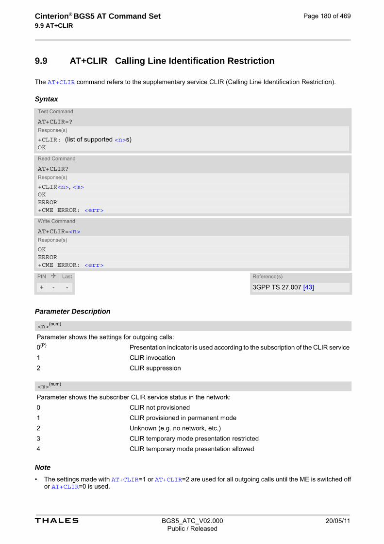
t BGS5_ATC_V02.000 20/05/11Public / Released
Cinterion® BGS5 AT Command Set 9.9 AT+CLIR
Page 180 of 469
9.9 AT+CLIR Calling Line Identification Restriction
The AT+CLIR command refers to the supplementary service CLIR (Calling Line Identification Restriction).
Syntax
Parameter Description
Parameter shows the settings for outgoing calls:
0(P) Presentation indicator is used according to the subscription of the CLIR service
1 CLIR invocation
2 CLIR suppression
Parameter shows the subscriber CLIR service status in the network:
0 CLIR not provisioned
1 CLIR provisioned in permanent mode
2 Unknown (e.g. no network, etc.)
3 CLIR temporary mode presentation restricted
4 CLIR temporary mode presentation allowed Note• The settings made with AT+CLIR=1 or AT+CLIR=2 are used for all outgoing calls until the ME is switched off
or AT+CLIR=0 is used.
Test Command
AT+CLIR=?Response(s)
+CLIR: (list of supported <n>s)OK
Read Command
AT+CLIR?Response(s)
+CLIR<n>, <m>OKERROR+CME ERROR: <err>
Write Command
AT+CLIR=<n>Response(s)
OKERROR+CME ERROR: <err>
PIN Last Reference(s)
+ - - 3GPP TS 27.007 [43]
<n>(num)
<m>(num)

t BGS5_ATC_V02.000 20/05/11Public / Released
Cinterion® BGS5 AT Command Set 9.10 AT+COLP
Page 181 of 469
9.10 AT+COLP Connected Line Identification Presentation
AT+COLP refers to the supplementary service COLP (Connected Line Identification Presentation) that enables a calling subscriber to get the connected line identity (COL) of the called party after setting up a mobile originated call. The command enables or disables the presentation of the COL at the TE. It has no effect on the execution of the supplementary service COLR in the network.
Syntax
Unsolicited Result CodeCall response format:
+COLP: <number>, <type> Parameter Description
0 Disable - suppress unsolicited result codes
1 Enable - display unsolicited result codes
0 COLP not provisioned (no presentation)
1 COLP provisioned
2 Unknown
String type phone number of connected address in format specified by <type>
Test Command
AT+COLP=?Response(s)
+COLP:(list of supported <n>s)OK
Read Command
AT+COLP?Response(s)
+COLP: <n>, <m>OKERROR+CME ERROR: <err>
Write Command
AT+COLP=[<n>]Response(s)
OKERROR+CME ERROR: <err>
PIN Last Reference(s)
+ - - 3GPP TS 27.007 [43]
<n>(num)
<m>(num)
<number>(str)

t BGS5_ATC_V02.000 20/05/11Public / Released
Cinterion® BGS5 AT Command Set 9.10 AT+COLP
Page 182 of 469
Type of address octet in integer format; 145 when dialling string includes international access code character "+", otherwise 129.
<type>(num)

t BGS5_ATC_V02.000 20/05/11Public / Released
Cinterion® BGS5 AT Command Set 9.11 AT+CPUC
Page 183 of 469
9.11 AT+CPUC Price per unit and currency table
The AT+CPUC read command returns the current parameters of PUC. The AT+CPUC write command sets the parameters of Advice of Charge related price per unit and currency table. SIM PIN2 is usually required to set the parameters.
Syntax
Parameter Description
Three-character currency code (e.g. "GBP", "EUR"). If the currency name is longer than three characters, all characters will be cut off after the third position. Before they are written to the SIM Card, these characters are converted to the standard GSM alphabet.
Price per unit; dot is used as a decimal separator (e.g. "2.66"). The length is limited to 20 characters. If the string length is exceeded, the command is terminated with an error. This string may only contain digits and a dot. Lead-ing zeros are removed from the string. The minimum and maximum value are determined by the structure of the SIM-PUCT file. The maximum price per unit value is 40950000000 (4095 x 10 exp 7). When successfully entered, this value is rounded to maximum accuracy. Note: Due to storage in mantisse (range 0-4095) and exponent (-7 to 7) it is possible that rounding errors occur.
SIM PIN2. String parameter which can contain any combination of digits. The maximum string length is limited to 8 digits. If this value is exceeded, the command terminates with an error message. If the PIN2 is incorrect, a CME error (+CME ERROR: incorrect password) is output. Parameter may be ommitted only if SIM PIN2 was correctly entered before.
Test Command
AT+CPUC=?Response(s)
OK
Read Command
AT+CPUC?Response(s)
+CPUC: <currency>, <ppu>OKERROR+CME ERROR: <err>
Write Command
AT+CPUC=<currency>, <ppu>[, <passwd>]Response(s)
OKERROR+CME ERROR: <err>
PIN Last Reference(s)
+ + - 3GPP TS 27.007 [43]
<currency>(str)(+CSCS)
<ppu>(str)
<passwd>(str)

t BGS5_ATC_V02.000 20/05/11Public / Released
Cinterion® BGS5 AT Command Set 9.11 AT+CPUC
Page 184 of 469
Example To change currency and/or price per unit you have two ways: You can enter PIN2 along with the AT+CPUC command:
Alternatively, you can first use the AT+CPIN2 command to enter PIN2.
AT+CPUC="EUR","0.10","8888" (where "8888" = PIN2)OK
AT+CPUC="EUR","0.10"OK SuccessfulAT+CPUC="EUR","0.10"+CME ERROR: SIM PIN2 required Attempt not successful. PIN2 authentication has
expired.

t BGS5_ATC_V02.000 20/05/11Public / Released
Cinterion® BGS5 AT Command Set 9.12 AT+CSSN
Page 185 of 469
9.12 AT+CSSN Supplementary service notifications
AT+CSSN enables or disables the presentation of URCs for supplementary services.
Syntax
Unsolicited Result Codes
URC 1
+CSSI: <code 1>
When <n>=1 and a supplementary service notification is received after a mobile originated call setup, inter-mediate result code "+CSSI: <code 1>" is sent to TE before any other MO call setup result codes
URC 2
+CSSU: <code 2>
When <m>=1 and a supplementary service notification is received during a mobile terminated call setup or during a call, unsolicited result code "+CSSU: <code 2>" is sent to TE.
Parameter Description
0(P) Suppress "+CSSI" URCs
1 Activate "+CSSI" URCs
0(P) Suppress "+CSSU" URCs
1 Activate "+CSSU" URCs
0 Unconditional call forwarding is active
Test Command
AT+CSSN=?Response(s)
+CSSN: (list of supported<n>s), (list of supported<m>s)OK
Read Command
AT+CSSN?Response(s)
+CSSN: <n>, <m>OK
Write Command
AT+CSSN=<n>[, <m>]Response(s)
OKERROR+CME ERROR: <err>
PIN Last Reference(s)
- - - 3GPP TS 27.007 [43]
<n>(num)
<m>(num)
<code 1>(num)

t BGS5_ATC_V02.000 20/05/11Public / Released
Cinterion® BGS5 AT Command Set 9.12 AT+CSSN
Page 186 of 469
1 Some of the conditional call forwardings are active
2 Call has been forwarded
3 Waiting call is pending
0 The incoming call is a forwarded call.
5 Held call was terminated by other party
10 Additional incoming call forwarded Note• URCs will be displayed only if the call concerned is a voice call, but some URCs will be displayed as well as
for data calls (like "+CSSI"=0).
<code 2>(num)
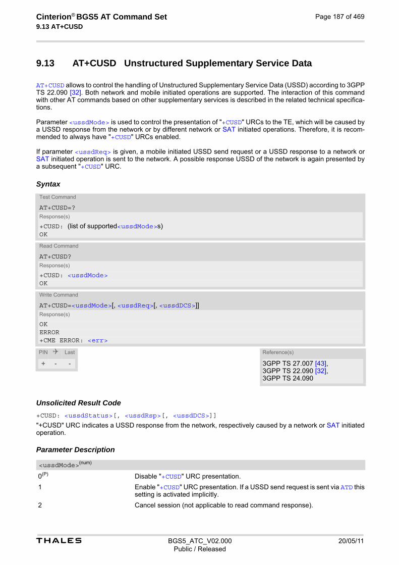
t BGS5_ATC_V02.000 20/05/11Public / Released
Cinterion® BGS5 AT Command Set 9.13 AT+CUSD
Page 187 of 469
9.13 AT+CUSD Unstructured Supplementary Service Data
AT+CUSD allows to control the handling of Unstructured Supplementary Service Data (USSD) according to 3GPP TS 22.090 [32]. Both network and mobile initiated operations are supported. The interaction of this command with other AT commands based on other supplementary services is described in the related technical specifica-tions. Parameter <ussdMode> is used to control the presentation of "+CUSD" URCs to the TE, which will be caused by a USSD response from the network or by different network or SAT initiated operations. Therefore, it is recom-mended to always have "+CUSD" URCs enabled. If parameter <ussdReq> is given, a mobile initiated USSD send request or a USSD response to a network or SAT initiated operation is sent to the network. A possible response USSD of the network is again presented by a subsequent "+CUSD" URC.
Syntax
Unsolicited Result Code+CUSD: <ussdStatus>[, <ussdRsp>[, <ussdDCS>]]
"+CUSD" URC indicates a USSD response from the network, respectively caused by a network or SAT initiated operation. Parameter Description
0(P) Disable "+CUSD" URC presentation.
1 Enable "+CUSD" URC presentation. If a USSD send request is sent via ATD this setting is activated implicitly.
2 Cancel session (not applicable to read command response).
Test Command
AT+CUSD=?Response(s)
+CUSD: (list of supported<ussdMode>s)OK
Read Command
AT+CUSD?Response(s)
+CUSD: <ussdMode>OK
Write Command
AT+CUSD=<ussdMode>[, <ussdReq>[, <ussdDCS>]]Response(s)
OKERROR+CME ERROR: <err>
PIN Last Reference(s)
+ - - 3GPP TS 27.007 [43], 3GPP TS 22.090 [32], 3GPP TS 24.090
<ussdMode>(num)

t BGS5_ATC_V02.000 20/05/11Public / Released
Cinterion® BGS5 AT Command Set 9.13 AT+CUSD
Page 188 of 469
Unstructured Supplementary Service Data (USSD) to be sent to the network. If <ussdReq> parameter is not given, network is not interrogated. AT+CUSD write command only supports set-ting <ussdDCS>=15.
Unstructured Supplementary Service Data (USSD) received from the network. If <ussdDCS> indicates that 3GPP TS 23.038 [33] GSM 7 bit default alphabet is used, the ME converts GSM alphabet into current TE character set according to rules of 3GPP TS 27.005 [42], Annex A. See also Section 1.7, Supported character sets. However, in case of invalid or omitted <ussdDCS>, conversion of <uss-dRsp> is not possible.
3GPP TS 23.038 [33] Cell Broadcast Data Coding Scheme (default 0). In case of an incoming USSD with invalid or omitted data coding scheme information <ussdDCS> will not be presented.
0 No further user action required (network initiated USSD notification, or no fur-ther information needed after mobile initiated operation).
1 Further user action is required (network initiated USSD request, or further infor-mation is needed after mobile initiated operation). If <ussdStatus>=1 the URC ends with ">" to prompt the TE for the response data. The input action is terminated with <CTRL-Z> or aborted with <ESC>.
2 USSD exchange is terminated by network.
3 A (ME local) client has responded, i.e. the interface was not idle and a busy indication was sent to the network.
4 Operation not supported (e.g. wrong input value given).
5 Network timeout. Note• It is recommended to finalize or escape a pending USSD user interaction before further actions are done to
prevent blocking situations.
<ussdReq>(str)(+CSCS)
<ussdRsp>(str)(+CSCS)
<ussdDCS>(num)
<ussdStatus>(num)

Cinterion® BGS5 AT Command Set 10. Internet Service Commands
t BGS5_ATC_V02.000 20/05/11Public / Released
Page 189 of 469
10. Internet Service Commands
BGS5 has an embedded TCP/IP stack that is driven by AT commands and enables the host application to easily access the Internet. The advantage of this solution is that it eliminates the need for the application manufacturer to implement own TCP/IP and PPP stacks, thus minimizing cost and time to integrate Internet connectivity into a new or existing host application. This chapter is a reference guide to all the AT commands and responses defined for use with the TCP/IP stack. The embedded TCP/IP stack provides the following services:
1. Socket services with client and server functionalities:
- TCP Client in Non-Transparent or Transparent Mode
- UDP Client in Non-Transparent or Transparent Mode
- Transparent TCP Listener
- Standard TCP Listener in Non-Transparent or Transparent Mode
- Non-Transparent UDP Endpoint
2. FTP Client
3. HTTP Client
4. SMTP Client
Step-by-step overview of how to configure and use TCP/IP communications with BGS5:
• Select URC mode or polling mode as described below.
• First of all, create a GPRS connection profile with AT^SICS. The connection profile is a set of basic param-eters which determines the type of connection to use for an Internet service. The connection type is also referred to as bearer. Up to 6 connection profiles can be defined, each identified by the <conProfileId>. For each configured connection profile there must be a free PDP context in AT+CGDCONT.
• Secondly, use AT^SISS to create a service profile based on one of the connection profiles. Up to 10 service profiles can be defined, each identified by the <srvProfileId>. The service profile specifies the type of Internet service to use, e.g., Socket, FTP, HTTP, SMTP. To assign a connection profile to a service profile, the <conProfileId> of AT^SICS must be entered as "conId" value of the AT^SISS parameter <srvPar-mTag>. This offers great flexibility to combine connection profiles and service profiles.
• Once the connection profile and the service profile are created, an Internet session can be opened by entering the AT^SISO write command and the desired <srvProfileId>. A URC indicates how to proceed. The "^SISW" URC means that data can be sent. The "^SISR" URC means that received data are available for reading. If an error occurs the "^SIS" URC is delivered instead.
• The next steps differ depending on the service type and the transfer mode (Non-Transparent or Transparent).
• Once a service is opened, the AT^SISI command shall be used to monitor the progress of the session. The command reports the service state of the used service profile and indicates the number of bytes received, the number of bytes sent and, in the case of sending, the number of bytes acknowledged or unacknowledged at TCP layer.
• If an error occurs during a session you can enter the AT^SISE command and the <srvProfileId> to iden-tify the reason. This is especially important in polling mode.
• The AT^SICI command can be used any time to query the current status of one or all connection profile(s).
• Finally, to close an opened service, enter the AT^SISC write command and the <srvProfileId>. AT^SISH disconnects a remote client from a Transparent TCP Listener without closing the listener (see also below).
• All profile settings of AT^SISS and AT^SICS are volatile. To store the settings to non-volatile memory and load the stored profiles AT^SIPS can be used.
Transparent Mode or Non-Transparent Mode:
• Transparent Mode is stream-oriented, i.e. a single data stream can be sent, and another single data stream can be received. Packetizing of data is done automatically by the embedded TCP/IP stack.
t BGS5_ATC_V02.000 20/05/11Public / Released
Cinterion® BGS5 AT Command Set
Page 190 of 469
Transparent Mode is activated with AT^SIST and then indicated by the "CONNECT" result code. The mode eliminates the need for AT^SISW and AT^SISR read and write sequences.
• Non-Transparent Mode is packet oriented, i.e. data is transferred in separate packets. Maximum packet size is 1500 bytes for TCP, 1460 bytes for UDP. To read and write data AT^SISW and AT^SISR sequences shall be used. FTP, HTTP, SMTP employ Non-Transparent Mode, for Socket services it is optional. To send or receive more than 1500 bytes, the read or write action shall be repeated until the data transfer has completed. Each read or write action requires that the command response (of AT^SISR or AT^SISW) con-firms that the service is ready to send or receive data. The read/write cycles can be controlled by URCs or polling. For details see below, section "URC mode and polling mode". To end an upload data stream set the <eodFlag> in the last AT^SISW command.
Listener services: A listener is waiting for incoming remote client requests. BGS5 supports two listener types: Transparent TCP Listener and Standard TCP Listener. After opening a listener with AT^SISO no "^SISW" URC appears. Instead, the "^SIS" URC with <urcCause> "5" shows that the opened listener is ready and starts listening. Additionally, the service state can be verified with AT^SISI which shows state "4" (Up - listening). An incoming remote client request is indicated by the "^SIS" URC. For details please refer to Section 10.14, Internet Service URC "^SIS", escpecially parameters <urcCause> and <urcInfoId>.
• Transparent TCP Listener:
- The Transparent TCP Listener can accept 1 remote client.
- To define a listener service profile as Transparent TCP Listener the "etx" parameter is mandatory in the address. See AT^SISS.
- AT^SISS allows some specific options for the Transparent TCP Listener service, such as "autoconnect", "connecttimeout", "addrfilter";
- If autoconnect is enabled an incoming remote client is indicated by the "^SIS" URC with <urcCause> "3" (Transparent) and <urcInfoId> "1" (= autoconnect enabled). The request is automatically accepted. The Listener profile instantly changes to Server mode (AT^SISO <socketState> to 4 = SERVER) and opens Transparent Mode (indicated by "CONNECT" result code).
- If autoconnect is disabled, an incoming remote client connection request is dynamically assigned to the next free service profile indicated as <srvProfileId> within the "^SIS" URC. The dynamically assigned <srvProfileId> shall be used to accept the remote client with AT^SISO, or to reject it with AT^SISC. Accepting with AT^SISO changes the dynamically assigned profile to Server mode (AT^SISO <socketState> to 4 = SERVER). For details see sections Section 10.14, Internet Service URC "^SIS" and Section 10.15.4, Transparent TCP Listener: Accepting / Rejecting Incoming Remote Client. If a remote client connection request is not accepted within the configured 'connecttimeout', it will be rejected automatically, and the URC "^SIS" is sent with <urcCause> set to '4'.
- As long as one remote client is connected all other remote client requests are rejected automatically with-out displaying the "^SIS" URC. The <rejCounter> in the response of the AT^SISO read command indi-cates such hidden rejects.
- AT^SISH disconnects a remote client, without closing the service, allowing the Transparent TCP Listener to wait for the next remote client. AT^SISC both disconnects the remote client and shuts down the Transparent TCP Listener.
- An example can be found in Section 10.14, Internet Service URC "^SIS" and Section 10.15.4, Transparent TCP Listener: Accepting / Rejecting Incoming Remote Client
• Standard TCP Listener:
- The Standard Listener can accept several remote clients. Each incoming remote client connection request is dynamically assigned to the next free service profile indicated as <srvProfileId> within the "^SIS" URC. <urcCause> in the "^SIS" URC equals "1" (Non-Transparent). The dynamically assigned <srvProfileId> shall be used to accept the remote client with AT^SISO, or to reject it with AT^SISC. The number of acceptable remote clients depends on the number of free service profiles.
- To transfer data it is possible to proceed with Transparent Mode using AT^SIST, or Non-Transparent Mode using AT^SISR and AT^SISW read / write sequences.
- An example can be found in Section 10.15.2, Configuring Non-Transparent Listener.
t BGS5_ATC_V02.000 20/05/11Public / Released
Cinterion® BGS5 AT Command Set
Page 191 of 469
Socket service used with UDP protocol The significant differences between the TCP and UDP protocols imply that UDP sometimes requires particular procedures or even specific parameters. Details on how to handle UDP services can be found in extra notes or are included in the general parameter descriptions. The BGS5 offers two kinds of Socket service with UDP protocol.
• UDP Client: Intended for connections to a given remote host. In this case the IP address and the UDP port of the remote host are set as a fixed parameter in the service profile. The UDP Client can use Transparent Mode and Non-Transparent Mode.
• Non-Transparent UDP Endpoint: IP address and UDP port of the remote hosts are handled in each read (AT^SISR) and write (AT^SISW) request. This enables the host application to communicate with different remote hosts. See example in Section 10.15.8, UDP Scenario.
Secure connection (TLS) All services support Transport Layer Security (TLS), except UDP client and Socket Listener. To set TLS simply add "s" to the address type, such as socktcps, ftps, https, smtps. For details see AT^SISS <srvParmTag> parameter "address". To create customized TLS certificates please refer to AT^SJMSEC and [3]. The processes of switching on/off certificate verification and adding/removing certificates for socktcps, ftps and smtps are same as those of https. Please refer to the description for https in AT^SJMSEC and [3]. The certificates should be installed on the FFS, and the boundary is determined by the size of FFS. Two design strategies for using Internet Service AT commands - URC mode or polling mode: The BGS5 offers two modes of controlling an Internet session opened with AT^SISO. To select the mode that best suits the preferences of your application design use the AT^SCFG command, parameter "Tcp/WithURCs" (refer to <tcpWithUrc>).
• URC mode (delivery default): The progress of an Internet session is URC driven. The URCs notify the host whether data can be sent or received, whether data transfer has completed, whether the service can be closed or whether an error has occurred. This mechanism eliminates the need to poll the service until the necessary progress information is received. To enable the URC mode select: AT^SCFG="Tcp/WithURCs",on.
• Polling mode: In polling mode, the presentation of URCs related to the Internet Services is disabled. The host is responsible to retrieve all the status information needed for controlling the Internet session. This is done by polling, where the host application keeps sending the commands AT^SISR, AT^SISW, AT^SISI. To enable the polling mode select: AT^SCFG="Tcp/WithURCs",off. The disabled URCs are the following: "^SISR" URC, "^SISW" URC and "^SIS" URC for parameter <urc-Cause>=0 (Internet service events), but not for <urcCause>=1 or 2 (needed for Socket listener and always enabled).
Maximum number of profiles defined / used:
• Up to 6 connection profiles can be created (with AT^SICS).
• Up to 10 service profiles can be created (with AT^SISS).
• A connection profile can be created on one interface and then viewed or changed on all other interfaces.
• A service profile can be used only on one interface at a time:
- Service profiles can only be opened on the interface where they have been defined with AT^SISS.
- Accordingly, on each interface the read commands AT^SISO? and AT^SISI? deliver full status informa-tion for the service profiles configured / opened on this interface, while service profiles related to other interfaces are only listed by <srvProfileId> and service type name (= <srvParmTag> value "srv-Type") without any status parameters.
- Changes to a service profile are allowed only on the same interface where it was created, trying to change it on another interface is denied with "+CME ERROR: invalid index". If queried with the read command AT^SISS? the entire profile is returned on the interface where the service profile was created, while on all other interfaces only the service type of the profile is stated.

t BGS5_ATC_V02.000 20/05/11Public / Released
Cinterion® BGS5 AT Command Set
Page 192 of 469
- To free a service profile for use on another interface, use the AT^SISS command and select service type = "none". This action deletes the entire profile and restores all parameters of the profile to their initial power-up state (all values are empty). For example, to remove the service profile 3, set AT^SISS=3,srv-Type,none. After this, a new profile 3 can be created on any other interface.
Address notation Server addresses must be provided as IPv4 addresses in standard dot format, e.g. "192.168.1.2", or as server address names resolvable by a DNS server. Timeouts Timeouts are not part of the Internet AT command functionality implemented in BGS5 and, if desired, are the responsibility of the host application. It is recommended that the host application validates URCs and AT com-mand responses and reacts adequately, for example by sending a close message or starting a timer. Using the DCD line to detect the connection status of Internet services With AT&C you can configure the DCD line of the used serial interface to indicate whether an Internet service is active. For Socket, HTTP the states "Up" or "Connecting" are indicated, for FTP and transparent TCP only the state "Up", for the Transparent TCP Listener service the states "Up", "Alerting", "Connected" and "Released".

t BGS5_ATC_V02.000 20/05/11Public / Released
Cinterion® BGS5 AT Command Set 10.1 AT^SICS
Page 193 of 469
10.1 AT^SICS Internet Connection Setup Profile
AT^SICS serves to create and edit Internet connection profiles. A connection profile can be assigned to one or more service profiles defined with AT^SISS, and thus, determines which type of connection is to be established when opening a service profile with AT^SISO. The AT^SICS read command requests the current settings of all Internet connection profiles. The AT^SICS write command specifies all parameters of a connection profile identified by <conProfileId>. To add or change the settings the write command needs to be executed for each single <conParmTag>. All pro-file parameters set with AT^SICS are volatile. To save profile settings in non-volatile memory please refer to AT^SIPS. BGS5 is designed to use PAP authentication (Password Authentication Protocol) when parameters "user" and "passwd" are given within the connection profile. If credentials are omitted, no authentication is performed. The list below shows which <conParmTag> parameters are mandatory (= m) or optional (= o).
Table 10.1: Applicability of AT^SICS <conParmTag> values
Syntax
<conParmTag> <conParmValue-conType> GPRS0
"conType" m
"user" o
"passwd" o
"apn" m
"inactTO" o
"dns1" o
Test Command
AT^SICS=?Response(s)
OK
Read Command
AT^SICS?Response(s)
^SICS: <conProfileId>, <conParmTag>, <conParmValue>[^SICS: ...]OK
Write Command
AT^SICS=<conProfileId>, <conParmTag>, <conParmValue>Response(s)
OK ERROR +CME ERROR: <err>
PIN Last
- + -
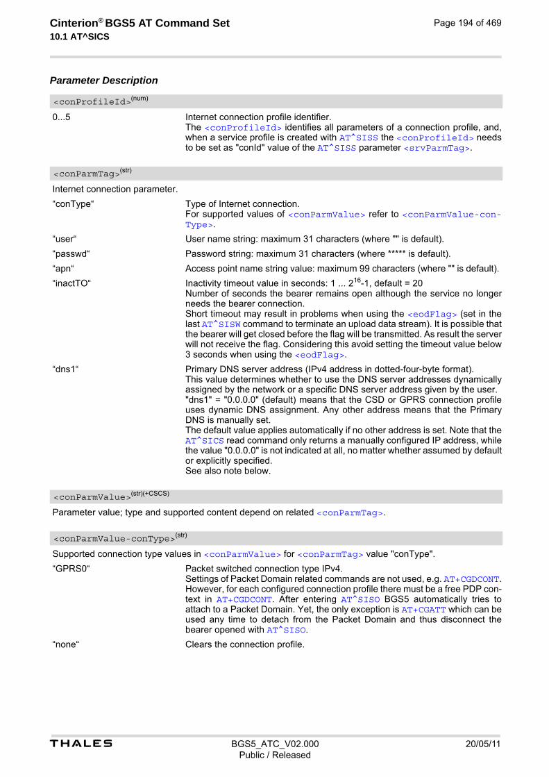
t BGS5_ATC_V02.000 20/05/11Public / Released
Cinterion® BGS5 AT Command Set 10.1 AT^SICS
Page 194 of 469
Parameter Description
0...5 Internet connection profile identifier. The <conProfileId> identifies all parameters of a connection profile, and, when a service profile is created with AT^SISS the <conProfileId> needs to be set as "conId" value of the AT^SISS parameter <srvParmTag>.
Internet connection parameter.
“conType“ Type of Internet connection. For supported values of <conParmValue> refer to <conParmValue-con-Type>.
“user“ User name string: maximum 31 characters (where "" is default).
“passwd“ Password string: maximum 31 characters (where ***** is default).
“apn“ Access point name string value: maximum 99 characters (where "" is default).
“inactTO“ Inactivity timeout value in seconds: 1 ... 216-1, default = 20 Number of seconds the bearer remains open although the service no longer needs the bearer connection. Short timeout may result in problems when using the <eodFlag> (set in the last AT^SISW command to terminate an upload data stream). It is possible that the bearer will get closed before the flag will be transmitted. As result the server will not receive the flag. Considering this avoid setting the timeout value below 3 seconds when using the <eodFlag>.
“dns1“ Primary DNS server address (IPv4 address in dotted-four-byte format). This value determines whether to use the DNS server addresses dynamically assigned by the network or a specific DNS server address given by the user. "dns1" = "0.0.0.0" (default) means that the CSD or GPRS connection profile uses dynamic DNS assignment. Any other address means that the Primary DNS is manually set. The default value applies automatically if no other address is set. Note that the AT^SICS read command only returns a manually configured IP address, while the value "0.0.0.0" is not indicated at all, no matter whether assumed by default or explicitly specified. See also note below.
Parameter value; type and supported content depend on related <conParmTag>.
Supported connection type values in <conParmValue> for <conParmTag> value "conType".
“GPRS0“ Packet switched connection type IPv4. Settings of Packet Domain related commands are not used, e.g. AT+CGDCONT. However, for each configured connection profile there must be a free PDP con-text in AT+CGDCONT. After entering AT^SISO BGS5 automatically tries to attach to a Packet Domain. Yet, the only exception is AT+CGATT which can be used any time to detach from the Packet Domain and thus disconnect the bearer opened with AT^SISO.
“none“ Clears the connection profile.
<conProfileId>(num)
<conParmTag>(str)
<conParmValue>(str)(+CSCS)
<conParmValue-conType>(str)

t BGS5_ATC_V02.000 20/05/11Public / Released
Cinterion® BGS5 AT Command Set 10.1 AT^SICS
Page 195 of 469
Notes• Before opening a service profile based on a connection profile recently used, check with AT^SICI that the
previous connection was properly closed. If AT^SICI confirms that the connection profile is in <conState> 0 (Down) the connection profile may be used again.
• If a GPRS network does not support or is not correctly configured for automatic DNS address assignment the TCP/IP stack cannot resolve fully qualified domain names. In this case, a warning message will be returned when trying to open an Internet service configured for automatic DNS address assignment.
10.1.1 Example: GPRS connection profile
at^sics=0,conType,GPRS0 Select connection type GPRS0.OKAT^SICS=0,"inactTO", "20" Inactivity timeout = 20s.OKAT^SICS=0,dns1,"193.254.160.1" IP address of Primary DNS server.OKAT^SICS=0,passwd,t-d1 Password for GPRS services provided by the Ger-
man operator T-D1.OKAT^SICS=0,apn,"internet.t-d1.de" APN to access the GPRS services provided by the
German operator T-D1.OK

t BGS5_ATC_V02.000 20/05/11Public / Released
Cinterion® BGS5 AT Command Set 10.2 AT^SICI
Page 196 of 469
10.2 AT^SICI Internet Connection Information
The AT^SICI read command requests the current status of the Internet connection profiles currently defined with AT^SICS. The AT^SICI write command displays the status of the specified Internet connection profile. If the connection profile is not defined yet, the command returns a "+CME ERROR" response.
Syntax
Parameter Description
Internet connection profile. Internet connection profile identifier as defined by AT^SICS (<conProfileId>).
0...5
State of the Internet connection profile.
0 Down - Internet connection is defined but not connected.
1 Connecting - A service has been opened and so the Internet connection is ini-tated.
2 Up - Internet connection is established and usable by one or more services.
3 Limited Up - Internet connection is established, but temporarily no network cov-erage.
4 Closing - Internet connection is terminating.
Test Command
AT^SICI=?Response(s)
^SICI:(list of supported <conProfileId>s)OK
Read Command
AT^SICI?Response(s)
[^SICI: <conProfileId>, <conState>, <numServices>, <conAddr>][^SICI: ...]OK
Write Command
AT^SICI=<conProfileId>Response(s)
^SICI: <conProfileId>, <conState>, <numServices>, <conAddr>OKERROR+CME ERROR: <err>
PIN Last
- - -
<conProfileId>(num)
<conState>(num)

t BGS5_ATC_V02.000 20/05/11Public / Released
Cinterion® BGS5 AT Command Set 10.2 AT^SICI
Page 197 of 469
Number of services using this Internet connection profile.
0...10
Local IPv4 address of the Internet connection profile ("0.0.0.0" if no address is associated yet). Notes• Before opening a service profile based on a connection profile recently used, check with AT^SICI that the
previous connection was properly closed. If AT^SICI confirms that the connection profile is in <conState> 0 (Down) the connection profile may be used again.
• If AT^SICI is used simultaneously on different instances only one request can be handled at a time. On the other instance(s) "+CME ERROR: operation temporary not allowed" will be displayed. If so, repeat the com-mand on this instance.
• After closing the last service which uses this connection profile, parameter value <numServices> is decreased after the expiry of the inactivity timeout "inactTO" of AT^SICS only.
10.2.1 Checking Connection Profile Status
Assume the network connection is temporarily not available. (If URC presentation mode of network registration is enabled the state is shown by the URC "+CREG: 2").
The network connection is temporarily not available but the Internet connection is still established, so the host may decide to stop the data transfer to minimize the risk of losing data due to memory limitations.
Another service has been opened with AT^SISO:
After closing one service with AT^SISC:
<numServices>(num)
<conAddr>(str)
at^sici? Query the current status of the connection profile.^SICI: 1,2,1,"10.10.0.161" One connection profile has been created at <con-
ProfileId>=1, and one service is opened using this connection profile. The Internet connection is in <conState>=2 ("Up").
OK
at^sici? Query once again the current status of the connec-tion profile.
^SICI: 1,3,1,"10.10.0.161" Parameter <conState> has changed to state "Lim-ited up".
OK
at^sici? Query once again the current status of the connec-tion profile.
^SICI: 1,2,1,"10.10.0.161" After re-establishing the network connection, <con-State> reverts to state "Up".
OK
at^sici? Query once again the current status of the connec-tion profile.
^SICI: 1,2,2,"10.10.0.161" After opening another service, parameter <numSer-vices> has increased.
OK
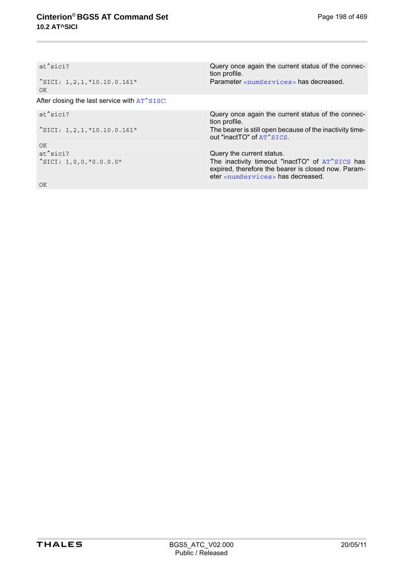
t BGS5_ATC_V02.000 20/05/11Public / Released
Cinterion® BGS5 AT Command Set 10.2 AT^SICI
Page 198 of 469
After closing the last service with AT^SISC:
at^sici? Query once again the current status of the connec-tion profile.
^SICI: 1,2,1,"10.10.0.161" Parameter <numServices> has decreased. OK
at^sici? Query once again the current status of the connec-tion profile.
^SICI: 1,2,1,"10.10.0.161" The bearer is still open because of the inactivity time-out "inactTO" of AT^SICS.
OKat^sici? Query the current status.^SICI: 1,0,0,"0.0.0.0" The inactivity timeout "inactTO" of AT^SICS has
expired, therefore the bearer is closed now. Param-eter <numServices> has decreased.
OK

t BGS5_ATC_V02.000 20/05/11Public / Released
Cinterion® BGS5 AT Command Set 10.3 AT^SIPS
Page 199 of 469
10.3 AT^SIPS Internet Profile Storage
AT^SIPS saves and loads the settings of the Internet connection and service profiles in the non-volatile memory. AT^SIPS can also be used to reset the settings to their default values without saving.
Syntax
Parameter Description
Internet profile storage type parameter.
“connection“ Handle AT^SICS parameter set.
“service“ Handle AT^SISS parameter set.
“all“ Handle AT^SICS parameters AT^SISS parameters listed above.
Internet profile storage action parameter
“reset“ Reset current profile(s) for given <type> to default settings without saving except profile(s) which have been opened by AT^SISO. If <ProfileId> is given only specific profile will be reset. Only the connections which are in "Down" status and the services which are in "Allocated" status could be affected.
“save“ Stores current profile(s) for given <type>. If <ProfileId> is given only specific profile will be stored.
“load“ Loads current profile(s) for given <type> except profile(s) which have been opened by AT^SISO. If <ProfileId> is given only specific profile will be loaded.
Internet connection or service profile storage identifier
0...9 In case of connection profile, max = 5, please see <conProfileId>. In case of a service profile, max = 9, please see <srvProfileId>. If parameter is omitted, AT^SIPS applies to all possible profile identifiers of used <type>.
Test Command
AT^SIPS=?Response(s)
^SIPS:(list of supported <type>s), (list of supported <action>s), (list of supported <ProfileId>s)OK
Write Command
AT^SIPS=<type>, <action>[, <ProfileId>]Response(s)
OK ERROR +CME ERROR: <err>
PIN Last
- + -
<type>(str)
<action>(str)
<ProfileId>(num)

t BGS5_ATC_V02.000 20/05/11Public / Released
Cinterion® BGS5 AT Command Set 10.4 AT^SISS
Page 200 of 469
10.4 AT^SISS Internet Service Setup Profile
AT^SISS serves to set up the necessary parameters in the Internet service profiles. Any service profile can then be used to control a data link in conjunction with AT^SISI, AT^SISO, AT^SISC, AT^SISR, AT^SISW, AT^SIST, AT^SISH and AT^SISE. The AT^SISS read command requests the current settings of all Internet service profiles. One line is issued for every possible parameter of a given <srvParmTag> "srvType" value. The AT^SISS write command specifies the parameters for a service profile identified by <srvProfileId>. At first the type of Internet service needs to be selected via <srvParmTag> value "srvType". This determines the applicability of all other <srvParmTag> values related to this "srvType" and sets their defaults. Changing the <srvParmTag> "srvType" of an existing service profile will reset all <srvParmTag> default values to suit the new "srvType". To change the settings the write command needs to be executed for each single <srvParmTag>. All profile parameters set with AT^SISS are volatile. To save profile settings in non-volatile memory please refer to AT^SIPS. The list below shows which <srvParmTag> parameters apply to each Internet service and which of them are mandatory (= m) or optional (= o).
Table 10.2: Applicability of AT^SISS <srvParmTag> values
<srvParmTag> Socket FTP HTTP SMTP
SrvType m m m m
conId m m m m
address m m m m
tcpMR o o o o
tcpOT o o o o
cmd m m o
path o o
files m o o
ftpath o
smFrom m
smRcpt m
smCC o
smSubj o
smHdr o
smMsg o
smAuth m
hcContent o
hcContLen m
hcUserAgent o
hcProp o
user o o o
passwd o o o
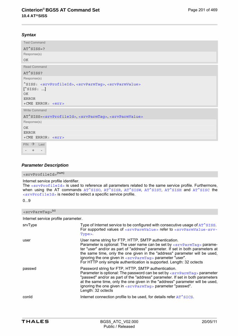
t BGS5_ATC_V02.000 20/05/11Public / Released
Cinterion® BGS5 AT Command Set 10.4 AT^SISS
Page 201 of 469
Syntax
Parameter Description
Internet service profile identifier. The <srvProfileId> is used to reference all parameters related to the same service profile. Furthermore, when using the AT commands AT^SISO, AT^SISR, AT^SISW, AT^SIST, AT^SISH and AT^SISC the <srvProfileId> is needed to select a specific service profile.
0...9
Internet service profile parameter.
srvType Type of Internet service to be configured with consecutive usage of AT^SISS. For supported values of <srvParmValue> refer to <srvParmValue-srv-Type>.
user User name string for FTP, HTTP, SMTP authentication. Parameter is optional: The user name can be set by <srvParmTag> parame-ter "user" and/or as part of "address" parameter. If set in both parameters at the same time, only the one given in the "address" parameter will be used, ignoring the one given in <srvParmTag> parameter "user". For HTTP only simple authentication is supported. Length: 32 octects
passwd Password string for FTP, HTTP, SMTP authentication. Parameter is optional: The password can be set by <srvParmTag> parameter "passwd" and/or as part of the "address" parameter. If set in both parameters at the same time, only the one given in the "address" parameter will be used, ignoring the one given in <srvParmTag> parameter "passwd". Length: 32 octects
conId Internet connection profile to be used, for details refer AT^SICS.
Test Command
AT^SISS=?Response(s)
OK
Read Command
AT^SISS?Response(s)
^SISS: <srvProfileId>, <srvParmTag>, <srvParmValue>[^SISS: ...]OKERROR+CME ERROR: <err>
Write Command
AT^SISS=<srvProfileId>, <srvParmTag>, <srvParmValue>Response(s)
OK ERROR +CME ERROR: <err>
PIN Last
- + -
<srvProfileId>(num)
<srvParmTag>(u)

t BGS5_ATC_V02.000 20/05/11Public / Released
Cinterion® BGS5 AT Command Set 10.4 AT^SISS
Page 202 of 469
address String value containing the URL for the specific service: If address contains a semicolon, quotes are mandatory. When GSM alphabet is enabled (see AT+CSCS) keep in mind that escape sequences are required for some special characters: For example, underscore "_" shall be escaped with \11. See also Section 1.7, Supported character sets for more information on character set and escape sequences.
1. Non-transparent Socket
- TCP client URL "socktcp[s]://<host>:<remotePort>[;keepi-dle=<value>][;keepcnt=<value>][;keepintvl=<value>]"
- TCP server URL "socktcp://listener:<localPort>[;keepi-dle=<value>][;keepcnt=<value>][;keepintvl=<value>]"
- UDP endpoint URL "sockudp://:<localPort>"
- UDP client URL "sockudp://<host>:<remotePort>[;port=<localPort>]"
2. Transparent Socket
- Transparent TCP client "socktcp[s]://<host>:<remotePort>;etx[=<etx-Char>][;timer=<value>][;keepidle=<value>][;keepcnt=<value>][;keep-intvl=<value>]"
- Transparent UDP client "sockudp[s]://<host>:<remotePort>;etx[=<etxChar>][;timer=<value>]"
- Transparent TCP Listener "socktcp://listener:<localPort>;etx[=<etxChar>][;timer=<value>][;autoconnect='0|1'][;connecttimeout=<value>][;keepi-dle=<value>][;keepcnt=<value>][;keepintvl=<value>][;addrfilter=<fil-ter>]"
Supported parameters for Socket services:
- <host>: IPv4 address in standard dot format, e.g. "192.168.1.2", or a DNS FQDN string.
- <remotePort>: 1 ... 216-1 for the remote port number.
- <localPort>: 1 ... 216-1 for the local port number.
- "port": Local port of UDP client: 0: Port number will be assigned from service (default). 1...216-1: defines the local port number for the UDP client.
- "etx": Parameter is mandatory for Transparent Socket. Otherwise Socket service is non-transparent.
- "<etxChar>": Specifies the character used to change from transparent access mode to AT command mode. range: 1...15,17...255 (16 is not allowed because it is used as DLE (0x10)) If parameter is not set no escaping is configured, thus requiring either +++ or DTR ON-OFF transition for changing to AT command mode. If value is set, the transmitted bytes are parsed for the DLE (0x10) char-acter followed by the specified <etxChar> value. If both characters are found the service returns to AT command mode without transmitting these two bytes (same as +++). If you wish to send DLE characters as normal text string within your pay-load data the characters shall be doubled (DLE DLE).
- "timer": The parameter configures the Nagle algorithm, which is used in transparent access mode. range: 20...[100]...500 milliseconds in steps of 20
- "keepidle": specifies the TCP parameter TCP_KEEPIDLE (see

t BGS5_ATC_V02.000 20/05/11Public / Released
Cinterion® BGS5 AT Command Set 10.4 AT^SISS
Page 203 of 469
RFC1122; not for Transparent UDP client) range: 1...65535 seconds; disabled if no value set (default).
- "keepcnt": specifies the TCP parameter TCP_KEEPCNT (see RFC1122; not for Transparent UDP client); ignored if option "keepidle" is not set range: 1...[9]...127
- "keepintvl": specifies the TCP parameter TCP_KEEPINTVL (see RFC1122; not for Transparent UDP client); ignored if option "keepidle" is not set range: 1...[75]...255 seconds
- "autoconnect" (for Transparent TCP Listener service only): 0 ... disabled (default) 1 ... automatically accept incoming client connects
- "connecttimeout": specifies the time after which incoming client con-nects are rejected automatically (for Transparent TCP Listener service only) range: 1...[30]...180 seconds
- "addrfilter": This option allows to filter incoming client connects based on the IP address of the client (for Transparent TCP Listener service only). It is possible to specify a maximum of 3 filters separated by commas. Each filter is specified as 4 numbers separated by dots ("<n>.<n>.<n>.<n>"). Each number n can be in the range between 0 and 254. It is allowed to use the wildcard "*" instead of n which matches all. The IP address of any incoming client connect does not match any of the specified filters, then the connect is rejected automatically. If the option is not specified, then all client connects are allowed. Example: "addrfilter=10.10.0.*,80.190.158.9" - allows connection requests from 10.10.0.81 and 80.190.158.9 but not from 10.10.17.81 and 80.190.158.10.
3. FTP "ftp[s]://[<user>:<passwd>@]<host>[:<port>/<path>]" "ftp://": The default TCP port 21 for ftp server is used. "ftps://": The default SSL port 990 for secure ftp server is used. <host>: element can be an IPv4 address, or a DNS FQDN string. <port>: element can be set optional and replace the default port. <user>: username for authentication, 32 octets. Can be set as part of "address" and/or separately by <srvParmTag> parameter "user". If set in both parameters at the same time, only the one given in the "address" parameter will be used, ignoring the one given in <srvParmTag> parame-ter "user". <passwd>: password for authentication, 32 octets. Can be set as part of "address" and/or separately by <srvParmTag> parameter "passwd". If set in both parameters at the same time, only the one given in the "address" parameter will be used, ignoring the one given in <srvParmTag> parame-ter "passwd". <path>: path of file or directory.
4. HTTP HTTP client URL Length: 6...255 "http[s]://[<user>:<passwd>@]<server>[:<port>/<path>]" <server>: element can be an FQDN, or an IPv4 address. <path>: path of file or directory. <port>: If parameter is omitted the service connects to HTTP default port 80. <user>: username for authentication, 32 octets. <passwd>: password for authentication, 32 octets. "https://": Used for SSL connection. Refer to "IETF-RFC 2616".
5. SMTP "smtp[s]://[<user>:<passwd>@]<host>[:<Port>]"

t BGS5_ATC_V02.000 20/05/11Public / Released
Cinterion® BGS5 AT Command Set 10.4 AT^SISS
Page 204 of 469
"smtp://": The default TCP port 25 for smtp server is used. "smtps://": The default SSL port 465 for secure smtp server is used. <host>: element can be an IPv4 address, or a DNS FQDN string. <port>: element can be set optional and replace the default port. <user>: username for authentication, 32 octets. Can be set as part of "address" and/or separately by <srvParmTag> parameter "user". If set in both parameters at the same time, only the one given in the "address" parameter will be used, ignoring the one given in <srvParmTag> parame-ter "user". <passwd> is for authentication, 32 octets. Can be set as part of "address" and/or separately by <srvParmTag> parameter "passwd". If set in both parameters at the same time, only the one given in the "address" parameter will be used, ignoring the one given in <srvParmTag> parameter "address".
cmd 1. HTTP service
- "0" or "get": Send HTTP GET request to server
- "1" or "post": Send HTTP POST request to server
- "2" or "head": Send HTTP HEAD request to server
2. FTP service
- get [<OffsetString>]: Get a single file from FTP server using AT^SISR.
- put [<OffsetString>]: Create and write a single file to FTP server using AT^SISW.
- dir: List the directory on the FTP server and show file size.
- list: List the directory on the FTP server without showing file size.
- fget: Get file(s) specified with <srvParmTag> parameter "files" from the FTP server and store the file(s) to the local FFS.
- fput: Send file(s) specified with <srvParmTag> parameter "files" from local FFS to FTP server.
- size: Request the size of the file element on the FTP server. The size result is output as "^SIS" URC.
- del: Delete a file specified with <srvParmTag> parameter "files" on FTP server.
- append: Append data to existing file on FTP server
- unique: Selects the FTP Store Unique command to create a file name unique to the current directory. If the file name is assigned by the server then the "^SIS" URC will appear, indicating <urcInfoId> 2100 and the file name.
<OffsetString> is an optional parameter for "get" and "put". It allows resum-ing a broken uplink or downlink transfer to resend data. The <OffsetString> value specifies the offset in number of octets to start the transfer from. Max-imum length is 16 digits. For "get" the <OffsetString> value must be calcu-lated from the <urcInfoId> 2100 of the "^SIS" URC requested before by using "size".
3. SMTP service
- files: Send file(s) specified with <srvParmTag> parameter "files" from the local FFS. Max. 5 files allowed.
- at: Send a single attachment to the server. The content of the attach-ment should be provided using AT^SISW after the service was opened with AT^SISO.
path Path on the local FFS. Specifies drive prefix and pathname. Optional for FTP and SMTP. Default: AT^SISS=<srvProfileId>,"path","file:///a:/".
ftpath Specifies a path on the remote FTP server after login. If no path is set the default path will be used.

t BGS5_ATC_V02.000 20/05/11Public / Released
Cinterion® BGS5 AT Command Set 10.4 AT^SISS
Page 205 of 469
files Specifies single or multiple files:
• Name of a single file for upload from the AT command interface to a server, or download from a server to the AT command interface if the "cmd" param-eter is given with "get" or "post" in case of HTTP, with "get", "put" or "del" in the case of FTP, or with "at" in the case of SMTP.
• Name(s) of file(s) located on the FFS when "cmd" parameter is given with parameters "fput" or "fget" in the case of FTP, or "files" in the case of SMTP. Maximum 5 files can be handled, separated by comma.
hcContent Optional parameter which defines the HTTP string if HTTP "post" is set with <srvParmTag> parameter "cmd". Length: 0...254 Can be used to transfer a small amount of data without the need for AT^SISW. The content of the "hcContent" string will only be sent if "hcContLen" = 0. To transmit a larger amount of data the "hcContLen" string shall set to a non-zero value. In this case the "hcContent" string will be ignored, and data trans-mission from the client to the server is done with AT^SISW. Usage example: AT^SISS=x,cmd,"POST" AT^SISS=x,hcContent,"This text will be sent to the server now ........ response OK" OK AT^SISS=x,hcContLen,0 AT^SISO=x OK ^SIS: x,0,2200,"Http connect 10.42.228.61:80" ^SISW: x,2
hcContLen Mandatory parameter if HTTP "post" is set with <srvParmTag> parameter "cmd". Length: 0...231-1 If "hcContLen" = 0 then the data given in the "hcContent" string will be posted without AT^SISW required. If "hcContLen" > 0 then AT^SISW command and "^SISW: x, 1" sequences will be used to send data from the client to the server. "hcContLen" may just be 1, or any other value > 0. There is no need to set the total amount of data with "hcContLen" (the given value would be ignored). The amount of data is deter-mined only the by single AT^SISW commands. Data trasmission must be ter-minated with end-of-data flag: AT^SISW=x,0,1>. See <eodFlag> for more information. See example in Section 10.15.17, HTTP Post.
hcUserAgent The user agent string must be set by the application to identify the mobile. Usu-ally operation system and software version info is set with this browser identi-fier. Length: 0...254
hcProp Parameter for several HTTP settings. Length: 0...254 The general format is 'key': <space> 'value' Multiple settings can be given separated by "\0d\0a" sequences within the string, do not put them at the end. Possible 'key' values are defined at HTTP/1.1 Standard RFC 2616.
smFrom Email sender address, i.e. "MAIL FROM" address (string). Length: 6...254 A valid address parameter consists of local part and domain name delimited by a '@' character, e.g. "[email protected]".

t BGS5_ATC_V02.000 20/05/11Public / Released
Cinterion® BGS5 AT Command Set 10.4 AT^SISS
Page 206 of 469
smRcpt Recipient address of the email, i.e. "RCPT TO" address (string). Length: 6...254 If multiple recipient addresses are to be supplied the comma character is used as delimiter to separate individual address values, e.g. "[email protected],[email protected]". Some mail servers do not accept recip-ient addresses without brackets <>. It is recommended to use the "RCPT TO" variable with brackets.
smCC CC recipient address of the email (string). Length: 6...254 If multiple CC recipient addresses are to be supplied the comma character is used as delimiter to separate individual address values, e.g. "[email protected],[email protected]".
smSubj Subject content of the email (string). Length: 0...254 If no subject is supplied the email will be sent with an empty subject.
smAuth SMTP authentication control flag (string). If "smAuth" = "0" or "none": No authentication (for test environment only, not applicable to real network) If "smAuth" = "1" or "plain" (default): Authentication with PLAIN authentification If "smAuth" = "2" or "login": Authentication with LOGIN authentification If "smAuth" = "3" or "cram": Authentication with CRAM authentification
smMsg SMTP message body. If no attachment is defined this is only the content of the email. Length: 0...254
tcpMR Parameter can be used to overwrite the global AT^SCFG parameter "Tcp/MaxRetransmissions" <tcpMr> for a specific Internet Service connection pro-file. If the parameter is not specified the value specified with AT^SCFG will be used. Supported values <srvParmValue> for this parameter are the same as described for <tcpMr>. Setting is not relevant for Internet Service "Socket" with type "UDP".
tcpOT Parameter can be used to overwrite the global AT^SCFG parameter "Tcp/Over-allTimeout" <tcpOt> for a specific Internet Service connection profile. If the parameter is not specified the value specified with AT^SCFG will be used. Supported values <srvParmValue> for this parameter are the same as described for <tcpOt>. Setting is not relevant for Internet Service "Socket" with type "UDP".
Parameter value; type and supported content depend on related <srvParmTag>.
Supported Internet service type values in <srvParmValue> for <srvParmTag> value "srvType". Before changing the "srvType" of an existing service profile be sure that the profile is closed. To verify the con-nection state of the service profile enter the read command AT^SISI. Only when <srvState>=2 is returned for this specific service profile you can change its service type.
“Socket“ BGS5 acting as client or server (listener) for TCP or UDP. "etx" subparameter in URL configures Transparent mode for Socket service. If BGS5 is TCP listener at least two service profiles are required. The first socket profile must be configured as listener. The second service profile will be dynamically assigned when a socket connection request from a remote client is incoming. For this purpose, one service profile must be left free (= not con-figured with AT^SISS). An incoming socket connection request will be indi-
<srvParmValue>(str)(+CSCS)
<srvParmValue-srvType>(str)

t BGS5_ATC_V02.000 20/05/11Public / Released
Cinterion® BGS5 AT Command Set 10.4 AT^SISS
Page 207 of 469
cated by the "^SIS" URC, with the next free <srvProfileId> shown inside the URC as parameter <urcInfoId>. The connection request can be accepted or rejected by using the commands AT^SISO or AT^SISC and the ID retrieved from the "^SIS".
“Ftp“ BGS5 acting as FTP client.
“Http“ BGS5 acting as HTTP client.
“Smtp“ BGS5 acting as SMTP client.
“none“ Reset Internet service profile settings. Operation is not allowed if profile is in use, i.e. it was activated via AT^SISO.
Parameter not supported Notes• String parameters are truncated if greater than the maximum length specified above.
• If AT^SISS is used simultaneously on different instances only one request can be handled at a time. On the other instance(s) "+CME ERROR: operation temporary not allowed" will be displayed. If so, repeat the com-mand on this instance.
<srvParmValue-alphabet>(str)
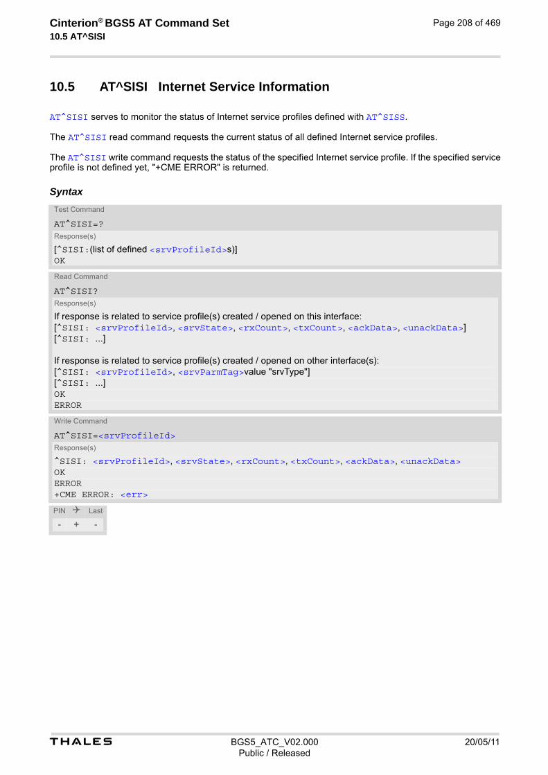
t BGS5_ATC_V02.000 20/05/11Public / Released
Cinterion® BGS5 AT Command Set 10.5 AT^SISI
Page 208 of 469
10.5 AT^SISI Internet Service Information
AT^SISI serves to monitor the status of Internet service profiles defined with AT^SISS. The AT^SISI read command requests the current status of all defined Internet service profiles. The AT^SISI write command requests the status of the specified Internet service profile. If the specified service profile is not defined yet, "+CME ERROR" is returned.
Syntax
Test Command
AT^SISI=?Response(s)
[^SISI:(list of defined <srvProfileId>s)]OK
Read Command
AT^SISI?Response(s)
If response is related to service profile(s) created / opened on this interface:[^SISI: <srvProfileId>, <srvState>, <rxCount>, <txCount>, <ackData>, <unackData>][^SISI: ...]
If response is related to service profile(s) created / opened on other interface(s):[^SISI: <srvProfileId>, <srvParmTag>value "srvType"][^SISI: ...]OKERROR
Write Command
AT^SISI=<srvProfileId>Response(s)
^SISI: <srvProfileId>, <srvState>, <rxCount>, <txCount>, <ackData>, <unackData>OKERROR+CME ERROR: <err>
PIN Last
- + -

t BGS5_ATC_V02.000 20/05/11Public / Released
Cinterion® BGS5 AT Command Set 10.5 AT^SISI
Page 209 of 469
Parameter Description
Internet service profile identifier as defined by AT^SISS (<srvProfileId>).
0...9
Internet service state (for details see AT^SISO parameter <srvState>).
2 Allocated
3 Connecting
4 Up
5 Closing
6 Down
7 Alerting
8 Connected
9 Released
Number of bytes received via AT^SISR or AT^SIST since last successful AT^SISO write command. This is the same value as displayed by the AT^SISO read command with the parameter <rxCount>.
Number of bytes sent via AT^SISW or AT^SIST since last successful AT^SISO write command. This is the same value as displayed by the AT^SISO read command with the parameter <txCount>.
Number of data bytes already sent and acknowledged at TCP layer. Value 0 indicates that no sent data is acknowledged yet. Parameter is not applicable to HTTP, SMTP, Socket with UDP. For these services the counter is always set to 0.
Number of data bytes already sent but not yet acknowledged at TCP layer. A value 0 indicates that all sent data is already acknowledged. This is the same value as displayed in the response of the AT^SISW write command with the parameter <unackData>. Parameter is not applicable to HTTP,SMTP, Socket with UDP. For these services the counter is always set to 0. <unackData> includes the overhead needed for encryption when TLS/SSL is used.
Note• If a service is in state "Down" or "Released" the responses for <rxCount>, <txCount>, <ackData> and
<unackData> are the last known values for the service in the states "Connecting", "Up/Listening", "Con-nected" and "Closing".
<srvProfileId>(num)
<srvState>(num)
<rxCount>(num)
<txCount>(num)
<ackData>(num)
<unackData>(num)

t BGS5_ATC_V02.000 20/05/11Public / Released
Cinterion® BGS5 AT Command Set 10.6 AT^SISO
Page 210 of 469
10.6 AT^SISO Internet Service Open
The AT^SISO write command starts the Internet session configured by the service profile. All further steps needed to control the session depend on whether you are using URC mode or polling mode. The AT^SISO read command returns the current status of all Internet services. URC mode (not for the Transparent TCP Listener service): If the service opens successfully, the URCs "^SISW" and "^SISR" will trigger the action to follow, either writing data with AT^SISW or reading data with AT^SISR. To terminate an upload data stream set the <eodFlag> within the last AT^SISW command. If the URCs notify that a data transfer has been successful ("^SISR: x, 2" or "^SISW: x, 2"), the service can be closed with AT^SISC. If a special event occurs, e.g. an error or a warning, after opening or while using a service then the URC type "^SIS" will be delivered. Polling mode: After opening the service, all progress information needed to control the session shall be explicitly requested by the host application. The particular sequence of AT commands varies depending on the service used. The fol-lowing list summarizes, by way of an example, the steps normally involved in managing an upload or download job.
• Upload (Socket, FTP, HTTP,SMTP):
- Enter the AT^SISO command, e.g. AT^SISO=9.
- Enter AT^SISW, specify <reqWriteLength>, e.g. AT^SISW=9,20. Check resulting response for <cnfWriteLength>. Optionally, check error with AT^SISE, e.g. AT^SISE=9. If necessary, repeat the sequence several times.
- Enter last AT^SISW command and enable <eodFlag>, e.g. AT^SISW=9,0,1. If Socket service: Query available data with AT^SISR, e.g. AT^SISR=9,1430.
- Check service state with AT^SISI, e.g. AT^SISI=9, if necessary several times until <srvState>=6 ("Down").
- Check error with AT^SISE, e.g. AT^SISE=9.
- Close service with AT^SISC, e.g. AT^SISC=9.
• Download (Socket, FTP, HTTP):
- Enter the AT^SISO command, e.g. AT^SISO=9.
- Enter AT^SISR, specify <reqReadLength>, e.g. AT^SISR=9,1000. Check resulting response for <cnfReadLength>. If necessary, repeat the sequence several times until <cnfReadLength>= -2 (end of data) or ERROR.
- Check error with AT^SISE, e.g. AT^SISE=9.
- Close service with AT^SISC, e.g. AT^SISC=9.
• Socket service (upload and download possible in one session):
- Recommended: Set AT+CMEE=2 to enable extended error text.
- Enter the AT^SISO command, e.g. AT^SISO=9.
- Enter AT^SISR or AT^SISW, specifying <reqReadLength> or <reqWriteLength>, e.g. AT^SISR=9,20 or AT^SISW=9,20. Check resulting response for <cnfReadLength> or <cnfWrite-Length>. If necessary, repeat the sequence several times.
- Check error with AT^SISE, e.g. AT^SISE=9.
- If write action: Enter last AT^SISW command and enable <eodFlag>, e.g. AT^SISW=9,0,1. 1) If Socket service: Query available data with AT^SISR, e.g. AT^SISR=9,1430.
- Close service with AT^SISC, e.g. AT^SISC=9.
• Transparent TCP client or Transparent UDP client:
- Enter the AT^SISO command, e.g. AT^SISO=9.
- Enter AT^SIST to enter transparent data mode. After communication has finished return to AT command mode via +++ escape sequence.
- Check error with AT^SISE, e.g. AT^SISE=9.
- Close service with AT^SISC, e.g. AT^SISC=9.

t BGS5_ATC_V02.000 20/05/11Public / Released
Cinterion® BGS5 AT Command Set 10.6 AT^SISO
Page 211 of 469
• Transparent TCP Listener:
- Enter the AT^SISO command, e.g. AT^SISO=9.
- Wait for URC "^SIS" which indicates a client connect.
- If auto answering is not enabled enter AT^SIST to enter transparent access mode.
- Wait for "CONNECT" which indicates that transparent access mode is active.
- After communication has finished terminate the client connection using DTR toggle or AT^SISH after leav-ing the transparent access mode.
- Close service with AT^SISC, e.g. AT^SISC=9.
Syntax
Parameter Description
<srvProfileId> 0 ... 9 specified with AT^SISS.
The type of the internet service as specified by the AT^SISS parameter <srvParmValue-srvType>.
Internet service state. Please note, that the state of an Internet service may influence the state of the serial DCD line. For details see description of value 2 for parameter <value> of command AT&C.
2 Allocated Service profile resources are allocated, i.e. at least the service type has been set (parameter <srvParmTag>, value "srvType" of AT^SISS). The service is not opened, but ready for configuration.
Test Command
AT^SISO=?Response(s)
OK
Read Command
AT^SISO?Response(s)
^SISO: <srvProfileId>, <srvType>[, <srvState>, <socketState>, <rxCount>, <txCount>, <locAddr>, <remAddr>, <rejCounter>][^SISO: ...]OK
Write Command
AT^SISO=<srvProfileId>[, <optParam>]Response(s)
OKERROR +CME ERROR: <err>
PIN Last
± - -
<srvProfileId>(num)
<srvType>(str)
<srvState>(num)
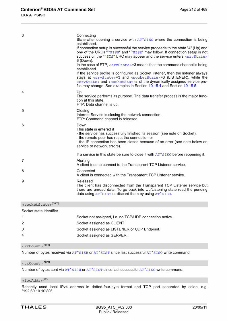
t BGS5_ATC_V02.000 20/05/11Public / Released
Cinterion® BGS5 AT Command Set 10.6 AT^SISO
Page 212 of 469
3 Connecting State after opening a service with AT^SISO where the connection is being established. If connection setup is successful the service proceeds to the state "4" (Up) and one of the URCs "^SISW" and "^SISR" may follow. If connection setup is not successful, the "^SIS" URC may appear and the service enters <srvState> 6 (Down). In the case of FTP, <srvState>=3 means that the command channel is being established. If the service profile is configured as Socket listener, then the listener always stays at <srvState>=3 and <socketState>=3 (LISTENER), while the <srvState> and <socketState> of the dynamically assigned service pro-file may change. See examples in Section 10.15.4 and Section 10.15.5.
4 Up The service performs its purpose. The data transfer process is the major func-tion at this state. FTP: Data channel is up.
5 Closing Internet Service is closing the network connection. FTP: Command channel is released.
6 Down This state is entered if - the service has successfully finished its session (see note on Socket), - the remote peer has reset the connection or - the IP connection has been closed because of an error (see note below on service or network errors). If a service in this state be sure to close it with AT^SISC before reopening it.
7 Alerting A client tries to connect to the Transparent TCP Listener service.
8 Connected A client is connected with the Transparent TCP Listener service.
9 Released The client has disconnected from the Transparent TCP Listener service but there are unread data. To go back into Up/Listening state read the pending data using AT^SIST or discard them by using AT^SISH.
Socket state identifier.
1 Socket not assigned, i.e. no TCP/UDP connection active.
2 Socket assigned as CLIENT.
3 Socket assigned as LISTENER or UDP Endpoint.
4 Socket assigned as SERVER.
Number of bytes received via AT^SISR or AT^SIST since last successful AT^SISO write command.
Number of bytes sent via AT^SISW or AT^SIST since last successful AT^SISO write command.
Recently used local IPv4 address in dotted-four-byte format and TCP port separated by colon, e.g. "192.60.10.10:80".
<socketState>(num)
<rxCount>(num)
<txCount>(num)
<locAddr>(str)

t BGS5_ATC_V02.000 20/05/11Public / Released
Cinterion® BGS5 AT Command Set 10.6 AT^SISO
Page 213 of 469
Remote IPv4 address in dotted-four-byte format and TCP port, separated by colon, e.g. "192.60.10.10:80". If the Socket service is configured as UDP Endpoint, a remote IP address cannot be assigned, and a default value will be shown instead.
Number of automatically rejected client connect attempts to a Transparent TCP Listener service because the service is already connected with a client.
[0] Normal Operation like AT^SISO= <srvProfileId>
1 Show only service parameter of <srvProfileId> Notes• If the bearer cannot be established and AT^SISO returns an error there might be a general network problem.
To identify the reason you can take advantage of the AT+CEER command. Using AT+CEER is especially rec-ommended when the <infoID> parameter of the AT^SISE command equals 0.
• If a service or network error occurs during an IP session and the "^SIS" URC or the AT^SISE command dis-play an error message, the service enters <srvState>=5 and then 6, i.e. the IP connection is closed. In this case, the service still allows reading the data stored in the buffer, but writing data is denied. After reading, close the service and open it again.
• If an FTP connection is no longer available after network loss or server shutdown a 3-minute closing timeout for each of the two used sockets takes effect, adding up to 6 minutes. The timeout is effective if the AT^SISC is not sent. Please keep in mind that this time may vary depending on the settings of <tcpMr> and <tcpOt>.
• As in polling mode no error URCs are available you are advised to integrate the commands AT^SISI and AT^SISE into the command sequences for upload and download jobs. So, the AT^SISO command may be followed by AT^SISI to check that the service has entered the <srvState>=4 before sending AT^SISR, AT^SISW or AT^SIST. This helps you to detect errors even though the "^SIS" URCs are disabled. A typical example is that the service fails to be opened because the service profile contains a wrong destination address. In such a case, after opening with AT^SISO and OK response, the service quickly enters the states <srvState>=2, 4 and 6, with an error being returned no earlier than after sending the first AT^SISR or AT^SISW command. In URC mode, an error URC, such as "Host not found" would be received in this situa-tion, but in polling mode the only way to detect the state is using AT^SISI or, alternatively, AT^SISO.
<remAddr>(str)
<rejCounter>(num)
<optParam>(num)

t BGS5_ATC_V02.000 20/05/11Public / Released
Cinterion® BGS5 AT Command Set 10.7 AT^SISC
Page 214 of 469
10.7 AT^SISC Internet Service Close
The AT^SISC write command closes the TCP/IP connection to the remote peer which was opened with AT^SISO. All resources are released, all status information parameters, e.g. <srvState>, <unackData>, <ackData>, <rxCount> and <txCount> counters, are reset. Only the initial configuration settings are pre-served. The service can be restarted any time, using the same configuration or a new one.
Syntax
Parameter Description
0...9 <srvProfileId> specified with AT^SISS.
Test Command
AT^SISC=?Response(s)
OK
Write Command
AT^SISC=<srvProfileId>Response(s)
OK ERROR +CME ERROR: <err>
PIN Last
± - -
<srvProfileId>(num)

t BGS5_ATC_V02.000 20/05/11Public / Released
Cinterion® BGS5 AT Command Set 10.8 AT^SISR
Page 215 of 469
10.8 AT^SISR Internet Service Read Data
The AT^SISR command either triggers a read operation (download) or queries the number of bytes in the internal buffer. The "^SISR: x, 1" URC is also used to report status changes of the transparent TCP service while the client is in AT command mode. The AT^SISR write command may return the following errors:
• "+CME ERROR: operation temporary not allowed" e.g. if the service has not network resources allocated.
• "+CME ERROR: operation not allowed" e.g. if the service is not configured.
Syntax
Unsolicited Result Code^SISR: <srvProfileId>, <urcCauseId>
Data availability status of the Internet service configured with AT^SISS has changed. The URC is issued when:
• data is available after opening an Internet service or
• less data was confirmed (in <cnfReadLength>) than requested (with <reqReadLength>) during the last "Read Data" operation and new data is available.
The URC is disabled in polling mode. See AT^SCFG, parameter "Tcp/WithURCs", <tcpWithUrc>. Parameter Description
<srvProfileId> 0 ... 9 specified with AT^SISS. Transparent TCP Listener services are not supported.
0 Peek Operator: Query number of received bytes within internal buffers. The behaviour of the peek operator depends on the selected Internet service, i.e. it may not be supported by all IP Services. For "Socket" service configured for UDP the size of the next available UDP packet is returned.
1...1500 Requested number of data bytes to be read via the Internet service specified in <srvProfileId>.
Test Command
AT^SISR=?Response(s)
OK
Write Command
AT^SISR=<srvProfileId>, <reqReadLength>Response(s)
^SISR: <srvProfileId>, <cnfReadLength>[, <remainUdpPacketLength>[, <Udp_RemClient>]]Number of data bytes are sent as specified by <cnfReadLength>. If peek operator was used no data bytes are sent. OKERROR+CME ERROR: <err>
PIN Last
- - +
<srvProfileId>(num)
<reqReadLength>(num)

t BGS5_ATC_V02.000 20/05/11Public / Released
Cinterion® BGS5 AT Command Set 10.8 AT^SISR
Page 216 of 469
-2 Indicates end of data. Data transfer has been finished (all data have been read) and the service can be closed with AT^SISC.
-1 Applies only to HTTP: Querying number of available bytes is not supported by the HTTP service.
0 Indicates that no further data is available at the moment.
>0 Number of available data bytes. The range is determined by <reqRead-Length>: If <reqReadLength> was greater than 0, then <cnfReadLength> may be less or equal to the value requested with <reqReadLength>. If <reqReadLength> equals 0 (peek operator) the value indicated by <cnfReadLength> may be greater than 1500.
Indicates whether or not data is available for reading with AT^SISR and AT^SIST.
1 Meaning of value "1" for all services except Transparent TCP service: Data is available and can be read by sending the AT^SISR command. The URC appears when less data was confirmed (in <cnfReadLength>) than requested (with <reqReadLength>) during the last "Read Data" operation and new data is available. Meaning of value "1" for Transparent TCP service: If the Transparent TCP service is in AT command mode the "^SISR: x, 1" URC notifies the client that the server has sent new data. In this case the client shall enter the AT^SIST command to go to transparent access mode and read the data.
2 End of data. Data transfer has completed (all data read). The service can be closed with AT^SISC.
Optional third parameter of the AT^SISR write command response displayed only if the Socket service uses the UDP protocol. The reception of each datagram must be completed before the next datagram can be received. This may be a problem if the buffer of the host application is limited and not designed to handle the maximum packet size of 1500 bytes. To compensate this, the host is advised to request, via <reqReadLength>, an amount less or equal its maxmimum buffer capacity and wait for the resulting AT^SISR write command response with param-eter <remainUdpPacketLength>. The benefit of this approach is that the host may properly receive all parts of a UDP datagram, as after each received data part the number of remaining bytes is synchronized, until read-ing the datagram is finished. If the currently read datagram is smaller than the number of bytes requested by the host the <remainUdpPack-etLength> parameter is omitted. Further write attempts with AT^SISR are denied as long as the <remainUdpPacketLength> is unequal 0 or is not omitted. In this case the service returns "+CME ERROR: operation of service temporary not allowed".
0 Indicates that all bytes of the current UDP datagram are read.
(max. data size)-1...1 Indicates that the currently read UDP datagram is not yet complete. The dis-played value is the remaining number of bytes. <remainUdpPacketLength> is unequal 0 until reading all parts of the cur-rent datagram is finished.
Service specific parameter of the AT^SISR write command response. If the Socket service is configured as UDP endpoint this parameter shows the IP address and the UDP port of the remote host that has sent the current UDP data. See example in Section 10.15.8, UDP Scenario.
<cnfReadLength>(num)
<urcCauseId>(num)
<remainUdpPacketLength>(num)
<Udp_RemClient>(str)

t BGS5_ATC_V02.000 20/05/11Public / Released
Cinterion® BGS5 AT Command Set 10.8 AT^SISR
Page 217 of 469
10.8.1 Example: Socket Host Reads Small Amounts of UDP Data Pack-ets (URC Mode)
This section applies only to the Socket service using the UDP protocol. The example shows how to read UDP packets if the buffer of the host application can handle only a few bytes. There are two datagrams available for reading. Buffer size: 6 bytes Datagram A = 18 bytes (content "THIS_IS_DATAGRAM_A") Datagram B = 3 bytes (content "NEW")
^SISR: 0,1 Service profile 0 is configured for Socket service and UDP. The URC notifies host that data is available for reading.
at^sisr=0,6 The host requests to read 6 bytes.^SISR: 0,6,12 THIS_I
The first 6 bytes of datagram A are confirmed and transmitted. Another 12 bytes are still available.
OKat^sisr=0,6 The host requests to read the next part of 6 bytes.^SISR: 0,6,6 S_DATA
The next 6 bytes of datagram A are confirmed and transmitted. Another 6 bytes are still available.
OKat^sisr=0,6 The host requests to read the next part of 6 bytes.^SISR: 0,6,0 GRAM_A
Last part of datagram A was received, no remainder is left.
OKat^sisr=0,6 Again, the host requests to read 6 bytes. This time, the request refers to
datagram B which has only 3 bytes. As the read datagram is smaller than the size requested by the host, the response does not include the <remainUdpPacketLength>.
^SISR: 0,3 NEW
3 bytes are confirmed and transmitted. Datagram B was properly received.
OK

t BGS5_ATC_V02.000 20/05/11Public / Released
Cinterion® BGS5 AT Command Set 10.9 AT^SISW
Page 218 of 469
10.9 AT^SISW Internet Service Write Data
AT^SISW triggers a write operation (upload) and queries the amount of data already sent, but not acknowledged at the TCP layer. AT^SISW write command may return the following errors:
• "+CME ERROR: operation temporary not allowed" e.g. if the service has not network resources allocated.
• "+CME ERROR: operation not allowed" e.g. if the service is not configured.
Syntax
Unsolicited Result Code^SISW: <srvProfileId>, <urcCauseId>
The URC indicates the following status changes:
• After opening a TCP Client or UDP Client with AT^SISO the "^SISW" URC indicates that the service is ready to accept data. After this initial "^SISW" URC, the TCP Client or UDP Client can proceed in Transparent Mode or Non-Transparent Mode. The initial "^SISW" URC is not issued after a Transparent Listener or UDP Endpoint was opened, because for listening services the "^SIS" URC will be issued.
• During AT^SISW write cycles the "^SISW" URC indicates that the service is ready to accept new data, or that data transfer has finished successfully.
The URC is disabled in polling mode. See AT^SCFG, parameter "Tcp/WithURCs", <tcpWithUrc>. Parameter Description
<srvProfileId> 0 ... 9 specified with AT^SISS. Transparent TCP Listener services are not supported.
0...1500
Specifies the number of bytes to be sent with AT^SISW or, if set to 0, requests the amount of data already sent with AT^SISW but not yet acknowledged:
• Parameter <reqWriteLength> may be 1...1500 bytes to specify the amount of data to be sent with AT^SISW.
Test Command
AT^SISW=?Response(s)
OK
Write Command
AT^SISW=<srvProfileId>, <reqWriteLength>[, <eodFlag>[, <Udp_RemClient>]]Response(s)
^SISW: <srvProfileId>, <cnfWriteLength>, <unackData>Number of data bytes as specified by <cnfWriteLength>. OKERROR+CME ERROR: <err>
PIN Last
± - +
<srvProfileId>(num)
<reqWriteLength>(num)

t BGS5_ATC_V02.000 20/05/11Public / Released
Cinterion® BGS5 AT Command Set 10.9 AT^SISW
Page 219 of 469
• If parameter <reqWriteLength> equals 0, AT^SISW does not expect any data, but a normal query is per-formed. This allows the application to explictly request, in particular at the end of an upload job, the amount of unacknowledged data at the TCP layer indicated by <unackData>.
• If Socket service is selected with UDP protocol
- <reqWriteLength>=0 can be used to send an empty UDP packet;
- it is recommended that the size of each data packet be limited to 1460 bytes. Otherwise, it is possible that the following URC occurs: "^SIS: <id>, 0, 9, The supplied buffer was too small / large".
End of data indication flag. See also Section 10.9.1.
[0] No end of data. Other data may follow to be transmitted via the Internet service. Note for UDP Endpoint service: Value 0 must be set before <Udp_RemClient> parameter although <eodFlag> is not effective for UDP Endpoint.
1 End of data is signalled to the Internet Service. Further AT^SISW write com-mands return an error response. However, reading data may be possible. The <eodFlag> is effective only if the <reqWriteLength> equals <cnfWrite-Length>, in particular if the <reqWriteLength> equals 0. End-of-data flag must be enabled for following actions: - FTP "cmd","put" (sending single file to FTP server) - SMTP "cmd","at" (sending attachment from AT command interface) - HTTP "cmd","post" if "hcContLen" is not equal zero (sending large amount of data)
Service specific parameter of the AT^SISW write command. If the Socket service is configured as UDP endpoint this parameter is mandatory and specifies the IP address (in dotted format) and the UDP port of the remote host. For each write request another IP address and UDP port may be given. See example in Section 10.15.8, UDP Scenario.
0...1500 Confirmed number of data bytes which can be transmitted via the Internet ser-vice configured in <srvProfileId>. This number may be less or equal to the value requested with <reqWriteLength>. The application has to deliver exactly the number of bytes indicated by <cnfWriteLength>. A 0 value means that no data can be written at this time, i.e. it serves as a flow control mechanism.
Number of data bytes already sent but not yet acknowledged at the TCP layer. The value is constantly changing until the entire upload job has completed. If the value equals 0 all data sent so far is acknowledged. <unackData> includes the <cnfWriteLength> value of the pending write operation. Therefore, the very first write operation of an upload job returns identical values for <cnfWriteLength> and <unackData>. This mechanism allows the host application to easily verify whether or not the remote host has successfully received the data. Parameter is not applicable to HTTP, SMTP, Socket with UDP protocol. For these services the counter is always set to 0.
1 The service is ready to accept new user data.
2 Data transfer has been finished successfully and Internet service may be closed without loss of data.
<eodFlag>(num)
<Udp_RemClient>(str)
<cnfWriteLength>(num)
<unackData>(num)
<urcCauseId>(num)
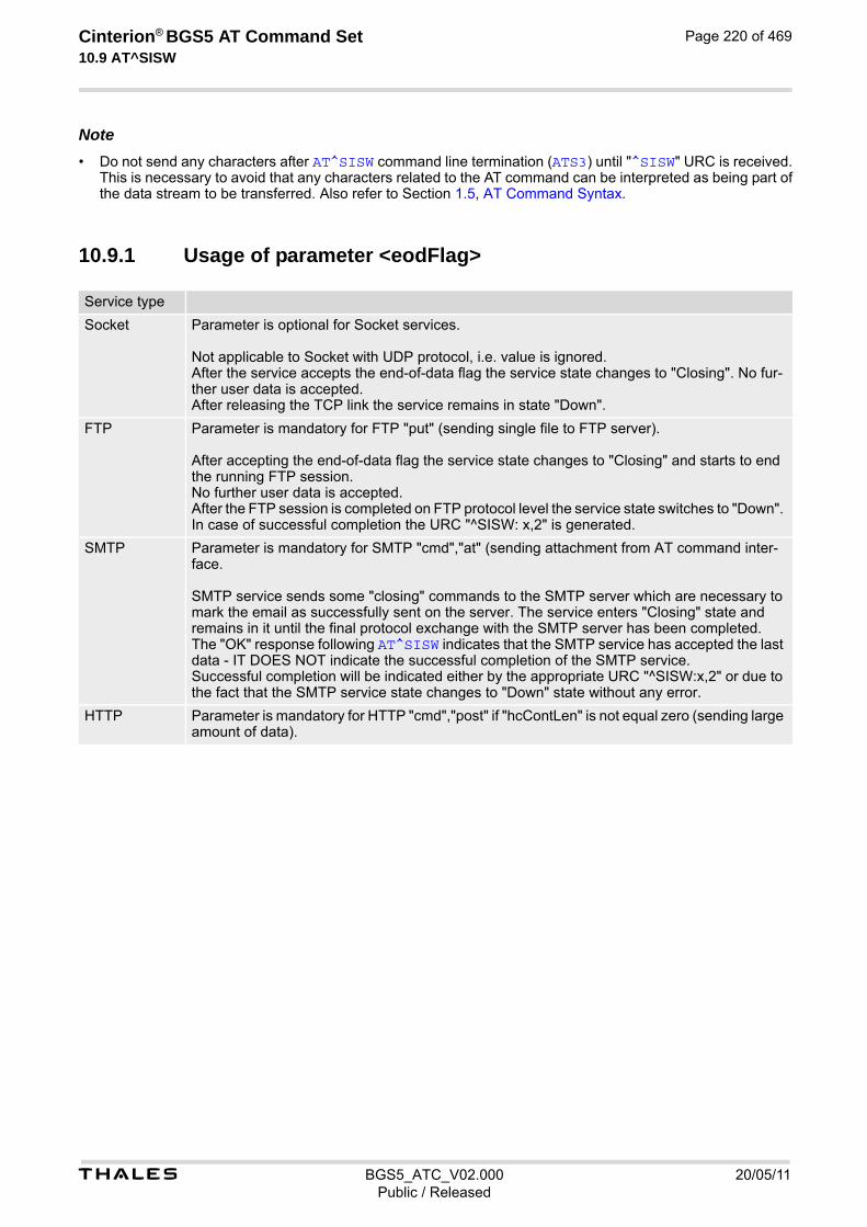
t BGS5_ATC_V02.000 20/05/11Public / Released
Cinterion® BGS5 AT Command Set 10.9 AT^SISW
Page 220 of 469
Note• Do not send any characters after AT^SISW command line termination (ATS3) until "^SISW" URC is received.
This is necessary to avoid that any characters related to the AT command can be interpreted as being part of the data stream to be transferred. Also refer to Section 1.5, AT Command Syntax.
10.9.1 Usage of parameter <eodFlag>
Service type
Socket Parameter is optional for Socket services. Not applicable to Socket with UDP protocol, i.e. value is ignored. After the service accepts the end-of-data flag the service state changes to "Closing". No fur-ther user data is accepted. After releasing the TCP link the service remains in state "Down".
FTP Parameter is mandatory for FTP "put" (sending single file to FTP server). After accepting the end-of-data flag the service state changes to "Closing" and starts to end the running FTP session. No further user data is accepted. After the FTP session is completed on FTP protocol level the service state switches to "Down". In case of successful completion the URC "^SISW: x,2" is generated.
SMTP Parameter is mandatory for SMTP "cmd","at" (sending attachment from AT command inter-face. SMTP service sends some "closing" commands to the SMTP server which are necessary to mark the email as successfully sent on the server. The service enters "Closing" state and remains in it until the final protocol exchange with the SMTP server has been completed. The "OK" response following AT^SISW indicates that the SMTP service has accepted the last data - IT DOES NOT indicate the successful completion of the SMTP service. Successful completion will be indicated either by the appropriate URC "^SISW:x,2" or due to the fact that the SMTP service state changes to "Down" state without any error.
HTTP Parameter is mandatory for HTTP "cmd","post" if "hcContLen" is not equal zero (sending large amount of data).

t BGS5_ATC_V02.000 20/05/11Public / Released
Cinterion® BGS5 AT Command Set 10.10 AT^SIST
Page 221 of 469
10.10 AT^SIST Enter Transparent Mode
AT^SIST activates / deactivates Transparent Mode. After entering the AT^SIST command, the CONNECT response notifies that the service has entered Transpar-ent Mode and is ready to transparently send and receive payload data over the AT command interface. There are several ways to quit the Transparent Mode and revert to AT Command Mode:
• +++ escape sequence
• DTR ON-OFF transitions (see AT&D for configuring DTR line)
• "etxChar" parameter set within the server address (see AT^SISS, <srvParmTag> "address" for Socket ser-vice URLs.
Switching back and forth between both modes does not affect the underlying socket and has no influence on the service <srvState>. If the service is in AT Command Mode the "^SISR: x, 1" URC appears once to indicate that the remote side has sent new data. In this case, the client or listener shall enter AT^SIST to go to Transparent Mode and read out the new data. If the connection is released by the remote side the following applies:
• If the service is in Transparent Mode (CONNECT mode): ME returns to AT Command Mode, issues the 2 bytes 0x10 (DLE) and 0x04 (EOT) before the final result code "NO CARRIER" and goes to <srvState> 6 ("Down") in case of client service and to 4 ("Up/Listening") in case of listener service. The presentation of the "NO CARRIER" result code depends on the ATV and ATQ settings.
• If the service is in AT Command Mode the "^SISR: x, 1" URC appears to indicate that the state of the service has changed. In this case, the client or listener shall go to Transparent Mode with AT^SIST in order to read remaining data (if any) and get the "NO CARRIER" result code. After this, the service changes to <srvState> 6 ("Down"). Otherwise, if the client or listener does not go to Transparent Mode after receiving "^SISR: x, 1" URC the service remains in <srvState> 4 ("Up") even though the remote side has shut down. In some cases, depending on the remote side and the network, it is possible that "^SIS" URCs may be reported, for example "^SIS" URCs with <urcInfoId> 15 ("Remote host has reset the connection") and 19 ("Socket has been shut down). See Section 10.14, Internet Service URC "^SIS" for a list of possible URCs.
• In all above scenarios, the Transparent service shall be closed with AT^SISC. Trying to return to Transparent Mode with AT^SIST would only end up with "NO CARRIER" once again and is not recommended.
• Use AT^SISO and AT^SISI to check the <srvState>.
Syntax
Test Command
AT^SIST=?Response(s)
OK
Write Command
AT^SIST=<srvProfileId>Response(s)
CONNECT(indicates that ME has entered Transparent Mode)OKERROR+CME ERROR: <err>
PIN Last
± - +

t BGS5_ATC_V02.000 20/05/11Public / Released
Cinterion® BGS5 AT Command Set 10.10 AT^SIST
Page 222 of 469
Parameter Description
<srvProfileId> 0 ... 9 specified with AT^SISS.
<srvProfileId>(num)

t BGS5_ATC_V02.000 20/05/11Public / Released
Cinterion® BGS5 AT Command Set 10.11 AT^SISH
Page 223 of 469
10.11 AT^SISH Disconnect Remote Client
AT^SISH is intendend only for a Transparent TCP Listener service. It allows to disconnect an established client connection from server side.
Syntax
Parameter Description
0...9 A Transparent TCP Listener service <srvProfileId> defined with AT^SISS.
Specifies disconnect mode.
[0] Socket is closed with graceful option
1 Socket is closed without graceful option
Test Command
AT^SISH=?Response(s)
OK
Write Command
AT^SISH=<srvProfileId>[, <mode>]Response(s)
OK ERROR +CME ERROR: <err>
PIN Last
- - -
<srvProfileId>(num)
<mode>(num)

t BGS5_ATC_V02.000 20/05/11Public / Released
Cinterion® BGS5 AT Command Set 10.12 AT^SISX
Page 224 of 469
10.12 AT^SISX Internet Service Execution
The AT^SISX command can be used to send ICMP (Internet Control Message Protocol) Echo Requests to a target IP address or DNS host name (also referred to as Ping command). The AT^SISX write command can be used any time while a connection profile (bearer) is active. If used while no connection is active (no profile opened) then the AT^SISX "Ping" command tries to use the default APN (no APN name). If the AT^SISX write command is executed for Ping, then the command returns one row for every ICMP Echo Request. The last Ping response line is followed by two lines to report a statistic calculated from the Echo Request responses. After starting the Ping command the AT channel is blocked until all ICMP requests are exe-cuted. To stop the periodic Ping early, send any character (user break).
Syntax
Parameter Description
“Ping“ Ping host.
The connection profile identifier as defined with AT^SICS for the connection to be used (see <conPro-fileId>). If the specified connection is not yet open, it will be opened implicitely.
In case of "Ping" this is the target host as FQDN or IP address (i.e. "192.168.1.3").
Test Command
AT^SISX=?Response(s)
^SISX:"Ping", (list of supported <conProfileId>s), , (range of supported <request>s), (range of supported <timelimit>s)OK
Write Command
AT^SISX=<service>, <conProfileId>, <address>[, <request>[, <timelimit>]]Response(s)
In case of <pingInfoType>= 1: ICMP Echo Requests (1 - 30 rows)^SISX:"Ping", <pingInfoType>, <conProfileId>, <ip-address>, <roundTripTime>[...]
In case of <pingInfoType>= 2: Packet statistic (1 row)^SISX:"Ping", <pingInfoType>, <conProfileId>, <sent>, <received>, <lost>, <lostPercent>
In case of <pingInfoType>= 3: Time statistic (1 row)^SISX:"Ping", <pingInfoType>, <conProfileId>, <minRTT>, <maxRTT>, <meanRTT>
OKERROR+CME ERROR: <err>
PIN Last
+ - -
<service>(str)
<conProfileId>(num)
<address>(str)

t BGS5_ATC_V02.000 20/05/11Public / Released
Cinterion® BGS5 AT Command Set 10.12 AT^SISX
Page 225 of 469
The IP address of the host (i.e. "192.168.1.3").
[1]...30 Number of "Ping" ICMP Echo Requests to be sent.
200...[5000]...10000 Amount of time, in milliseconds, to wait for an ICMP Echo Response message related to a previously sent Echo Request message.
Indicate the type and format of the information given in the command responses (see syntax of the AT^SISX write command above).
1 Ping status received for the ICMP Echo Request(s). Depending on parameter <request> 1 - 30 rows. Address and Round Trip Time are returned for each request.
2 one row packet statistic calculated from the ping response(s) received for <pingInfoType>=1.
3 one row time statistics calculated from the ping response(s) received for <pingInfoType>=1 (displayed only if at least one Echo response message was received).
Round Trip Time in milliseconds. If the Echo Response message is not received within the time specified by <timelimit> the value -1 is returned (e.g. when the bearer shuts down during command execution).
Number of sent packets.
Number of received packets.
Number of lost packets.
Lost packets in percent.
Minimum Round Trip Time in milliseconds.
Maximum Round Trip Time in milliseconds.
Average Round Trip Time in milliseconds.
<ip-address>(str)
<request>(num)
<timelimit>(num)
<pingInfoType>(num)
<roundTripTime>(num)
<sent>(num)
<received>(num)
<lost>(num)
<lostPercent>(num)
<minRTT>(num)
<maxRTT>(num)
<meanRTT>(num)

t BGS5_ATC_V02.000 20/05/11Public / Released
Cinterion® BGS5 AT Command Set 10.13 AT^SISE
Page 226 of 469
10.13 AT^SISE Internet Service Error Report
The AT^SISE write command returns the current error status of the specified Internet service profile. If the ser-vice profile is not defined or the value is invalid "+CME ERROR" response is returned. The error status is identical to the content of the "^SIS" URC last issued. If a service fails the commands AT^SISR, AT^SISW or AT^SIST will return an error response. However, if the AT^SISE command returns <infoID>=0 it is recommended to use the AT+CEER command because a general network problem might be the reason.
Syntax
Parameter Description
Internet service profile identifier as defined by AT^SISS <srvProfileId>.
0...9
Reason for Internet service error. This is a subset of the <urcInfoId>s which can be found in Section 10.14, Internet Service URC "^SIS". The value 0 indicates there is no special Internet service error. In this case the application may use AT+CEER to check for general network problems.
Information text related to <infoID>. This is a subset of the <urcInfoText>s which can be found in Section 10.14, Internet Service URC "^SIS".
Note• In particular cases, the AT^SISE command may deliver information and warnings. This applies the following
services: FTP: Information 2100 SMTP: Warnings If an error occurs the information and warning messages are overwritten by error messages.
Test Command
AT^SISE=?Response(s)
OK
Write Command
AT^SISE=<srvProfileId>Response(s)
^SISE: <srvProfileId>, <infoID>[, <info>]OKERROR+CME ERROR: <err>
PIN Last
- - -
<srvProfileId>(num)
<infoID>(num)
<info>(str)
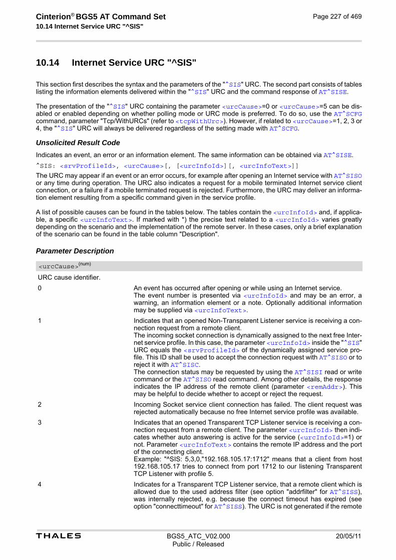
t BGS5_ATC_V02.000 20/05/11Public / Released
Cinterion® BGS5 AT Command Set 10.14 Internet Service URC "^SIS"
Page 227 of 469
10.14 Internet Service URC "^SIS"
This section first describes the syntax and the parameters of the "^SIS" URC. The second part consists of tables listing the information elements delivered within the "^SIS" URC and the command response of AT^SISE. The presentation of the "^SIS" URC containing the parameter <urcCause>=0 or <urcCause>=5 can be dis-abled or enabled depending on whether polling mode or URC mode is preferred. To do so, use the AT^SCFG command, parameter "Tcp/WithURCs" (refer to <tcpWithUrc>). However, if related to <urcCause>=1, 2, 3 or 4, the "^SIS" URC will always be delivered regardless of the setting made with AT^SCFG.
Unsolicited Result CodeIndicates an event, an error or an information element. The same information can be obtained via AT^SISE.
^SIS: <srvProfileId>, <urcCause>[, [<urcInfoId>][, <urcInfoText>]]
The URC may appear if an event or an error occurs, for example after opening an Internet service with AT^SISO or any time during operation. The URC also indicates a request for a mobile terminated Internet service client connection, or a failure if a mobile terminated request is rejected. Furthermore, the URC may deliver an informa-tion element resulting from a specific command given in the service profile. A list of possible causes can be found in the tables below. The tables contain the <urcInfoId> and, if applica-ble, a specific <urcInfoText>. If marked with *) the precise text related to a <urcInfoId> varies greatly depending on the scenario and the implementation of the remote server. In these cases, only a brief explanation of the scenario can be found in the table column "Description". Parameter Description
URC cause identifier.
0 An event has occurred after opening or while using an Internet service. The event number is presented via <urcInfoId> and may be an error, a warning, an information element or a note. Optionally additional information may be supplied via <urcInfoText>.
1 Indicates that an opened Non-Transparent Listener service is receiving a con-nection request from a remote client. The incoming socket connection is dynamically assigned to the next free Inter-net service profile. In this case, the parameter <urcInfoId> inside the "^SIS" URC equals the <srvProfileId> of the dynamically assigned service pro-file. This ID shall be used to accept the connection request with AT^SISO or to reject it with AT^SISC. The connection status may be requested by using the AT^SISI read or write command or the AT^SISO read command. Among other details, the response indicates the IP address of the remote client (parameter <remAddr>). This may be helpful to decide whether to accept or reject the request.
2 Incoming Socket service client connection has failed. The client request was rejected automatically because no free Internet service profile was available.
3 Indicates that an opened Transparent TCP Listener service is receiving a con-nection request from a remote client. The parameter <urcInfoId> then indi-cates whether auto answering is active for the service (<urcInfoId>=1) or not. Parameter <urcInfoText> contains the remote IP address and the port of the connecting client. Example: "^SIS: 5,3,0,"192.168.105.17:1712" means that a client from host 192.168.105.17 tries to connect from port 1712 to our listening Transparent TCP Listener with profile 5.
4 Indicates for a Transparent TCP Listener service, that a remote client which is allowed due to the used address filter (see option "addrfilter" for AT^SISS), was internally rejected, e.g. because the connect timeout has expired (see option "connecttimeout" for AT^SISS). The URC is not generated if the remote
<urcCause>(num)

t BGS5_ATC_V02.000 20/05/11Public / Released
Cinterion® BGS5 AT Command Set 10.14 Internet Service URC "^SIS"
Page 228 of 469
client is rejected because its IP address is not matching the address filters. If <urcCause> equals "4", then <urcInfoId> always equals "0". This cause is also used if ME is not in Transparent Mode and a connected cli-ent has closed the connection remotely.
5 Only for TCP Listeners, Non-Transparent UDP endpoint. The service is ready to use.
Information identifier related to <urcCause>. See tables below for further detail. The <urcInfoId> number ranges indicate the type of information element: 0: Service is working properly. 1 - 2000: Error, service is aborted and enters <srvState>=6 (Down). Value 1000 notifies that service profile contains invalid parameter(s). 2001 - 4000: Information related to progress of service. 4001 - 6000: Warning, but no service abort. 6001 - 8000: Notes Additional information for Socket service: As stated above, if a Socket connection request from a remote client is received (see <urcCause>=1) the <urcInfoId> shows the <srvProfileId> of the dynamically assigned free service profile. If <urcCause> is 3, the <urcInfoId> is used as auto answer indicator. If autoconnect is enabled the value is 1. If autoconnect is disabled the value shows the <srvProfileId> of the dynamically assigned profile for the incoming remote client connection request.
Information text related to <urcCause>. See tables below for further detail. The maximum length of an infor-mation text is 255 bytes. Any longer messages will be truncated. If <urcCause> is 3, <urcInfoText> is used to indicate the IP address and port of the connecting client, e.g. "192.168.105.17:1712".
10.14.1 Information Elements Related to the Service Application
The following table lists the informatiomation elements which may be returned by all supported services within the "^SIS" URC and the command response of AT^SISE. It should be noted that TCP/IP socket problems may occur in all Internet service connections (Socket, Transparent TCP or Transparent UDP, FTP,HTTP or SMTP).
<urcInfoId>(num)
<urcInfoText>(str)
<urcInfoId> <urcInfoText> Description
Information Elements Returned by the TCP/IP socket
2 Invalid socket descriptor Socket error
3 Bad address specified Socket error
4 Invalid operation Socket error
5 No free socket descriptors Socket error
6 The operation would block Socket error
7 A previous attempt at this operation is still ongoing Socket error
8 Socket is not bound Socket error
9 The supplied buffer is too small / large Socket error
10 Flags not supported Socket error
11 Operation not supported Socket error
12 The address is already in use Socket error
13 The network is unavailable Socket error

t BGS5_ATC_V02.000 20/05/11Public / Released
Cinterion® BGS5 AT Command Set 10.14 Internet Service URC "^SIS"
Page 229 of 469
14 An established connection was aborted (transmission time-out or protocol error)
Socket error
15 Remote host has reset the connection Socket error
16 No buffer space available Socket error
17 The socket is already connected Socket error
18 For TCP/IP sockets, the socket is not connected Socket error
19 Socket has been shut down Socket error
20 Connection timed out Socket error
21 Remote host has rejected the connection Socket error
22 Remote host is unreachable Socket error
23 An unexpected error occurred Socket error
24 Host not found DNS error
25 An error occurred that may be transient; a further attempt may succeed.
DNS error
26 An unrecoverable error occurred DNS error
General Information Elements
46 Fatal: The service has detected an unknown error
47 *) Indicates that the remote ser-vice has closed the connection. The host shall close the service.
48 Remote peer has closed the connection Remote peer has closed the connection unexpectedly, and no data are available. The host shall close the service. Note that the "^SIS" URC only indicates the <urcInfoId>, but the AT^SISE command indicates both the <urcIn-foId> and the <urcInfo-Text>.
49 Fatal: No memory is available for service action
50 Fatal: Service has detected an internal error
51 Application Task ID is not registered
52 Fatal: Entity not supported
53 No free Entity available
54 Index not supported
55 Service is not writeable
56 Syntax error in URL
57 Configuration Error
58 No more data available
59 Peek operation rejected
60 Service don't accept further data
61 Fatal: Service has no socket connection
80 Connection profile not defined.
84 PPP LCP FAILED PPP error
85 PAP Authentication failed PPP error
<urcInfoId> <urcInfoText> Description

t BGS5_ATC_V02.000 20/05/11Public / Released
Cinterion® BGS5 AT Command Set 10.14 Internet Service URC "^SIS"
Page 230 of 469
*) Text varies depending on scenario.
10.14.2 Information Elements Related to FTP Service
86 CHAP Authentication failed PPP error
87 IPCP failed PPP error
89 PDP: can not obtain controling task
90 PDP: internal error 1
91 PDP: internal error 2
92 PDP: no authentication req
93 PDP: internal error 3
94 PDP: conection failed
95 PDP: internal error 4
96 PDP: no IP assigned
97 PDP: no network
98 PDP: network is not up
99 PDP: internal error 5
119 PDP: no DNS received
120 DNS: no data
121 DNS: timeout
122 DNS: connection refused
123 DNS: terminated lookup
124 DNS: domain name is too long
125 DNS: invalid server
126 DNS: undefined error
General Information Elements
1000 PARA-ERR: <Info> Notifies that service profile con-tains a wrong parameter. <Info> text indicates the service profile parameter that contains an error.
6001 General progress information for connection setup.
<urcInfoId> <urcInfoText> Description
Error URCs
100 FTP-ERR: <FTP Response Str> <FTP Response Str> text depends on FTP server imple-mentation
Info URCs
2100 <info> <info> text depends on FTP server implementation
<urcInfoId> <urcInfoText> Description
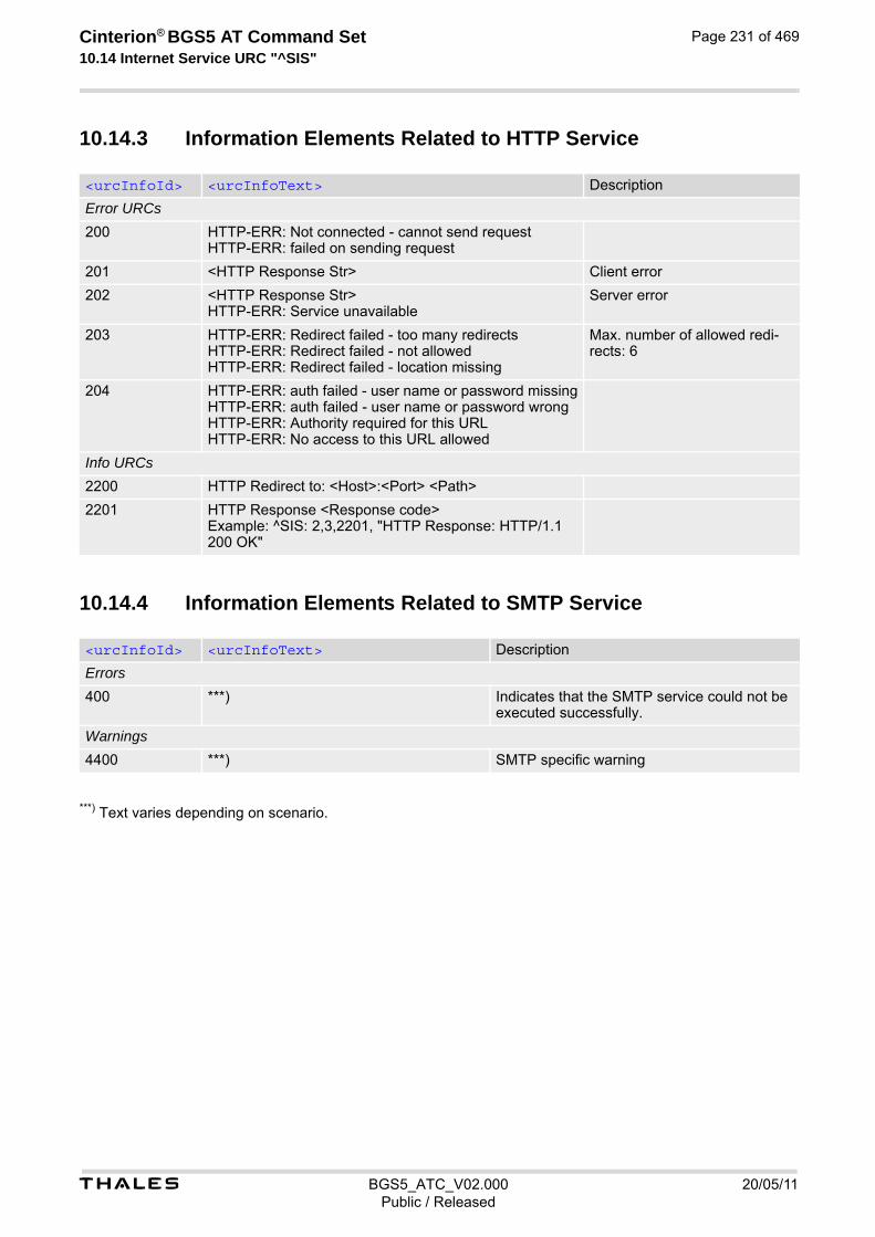
t BGS5_ATC_V02.000 20/05/11Public / Released
Cinterion® BGS5 AT Command Set 10.14 Internet Service URC "^SIS"
Page 231 of 469
10.14.3 Information Elements Related to HTTP Service
10.14.4 Information Elements Related to SMTP Service
***) Text varies depending on scenario.
<urcInfoId> <urcInfoText> Description
Error URCs
200 HTTP-ERR: Not connected - cannot send request HTTP-ERR: failed on sending request
201 <HTTP Response Str> Client error
202 <HTTP Response Str> HTTP-ERR: Service unavailable
Server error
203 HTTP-ERR: Redirect failed - too many redirects HTTP-ERR: Redirect failed - not allowed HTTP-ERR: Redirect failed - location missing
Max. number of allowed redi-rects: 6
204 HTTP-ERR: auth failed - user name or password missing HTTP-ERR: auth failed - user name or password wrong HTTP-ERR: Authority required for this URL HTTP-ERR: No access to this URL allowed
Info URCs
2200 HTTP Redirect to: <Host>:<Port> <Path>
2201 HTTP Response <Response code> Example: ^SIS: 2,3,2201, "HTTP Response: HTTP/1.1 200 OK"
<urcInfoId> <urcInfoText> Description
Errors
400 ***) Indicates that the SMTP service could not be executed successfully.
Warnings
4400 ***) SMTP specific warning

t BGS5_ATC_V02.000 20/05/11Public / Released
Cinterion® BGS5 AT Command Set 10.15 Examples of how to Configure and Use Internet Service Profiles
Page 232 of 469
10.15 Examples of how to Configure and Use Internet Service Profiles
Below you can find selective examples of how to configure and use Internet service profiles. To visualize the dif-ference between URC mode and polling mode the operation of services (after opening with AT^SISO) is explained in separate examples for either mode. For all examples it is assumed that a connection profile has been created as explained in Section 10.1.1. When GSM alphabet is enabled (see AT+CSCS) keep in mind that escape sequences are required for some spe-cial characters: For example, underscore "_" shall be escaped with \11. See also Section 1.7, Supported char-acter sets for more information on character set and escape sequences.
10.15.1 Selecting URC Mode or Polling Mode
To enable or disable the presentation of URCs for the Internet services use the AT^SCFG command, type "TcpIp/WithURCs" and select "on" or "off" for parameter <tcpWithUrc>.
10.15.2 Configuring Non-Transparent Listener
Keep in mind that if the host is configured as Non-transparent Listener another service profile must be left free to be dynamically assigned as Server when the Non-Transparent Listener receives a connection request from a remote client. Configure the service profile 4 for use as Non-Transparent Listener:
Open the Socket service and query the IP address dynamically assigned to the Socket listener:
at^scfg=tcp/withurcs Query the current setting.^SCFG: "Tcp/WithURCs","on" URC mode is enabled (delivery default).OKat^scfg=tcp/withurcs,off Select polling mode (by switching off URC mode).^SCFG: "Tcp/WithURCs","off" Polling mode is accepted.OK
AT^SISS=4,srvType,"Socket" Select service type Socket.OKAT^SISS=4,conId,0 Select connection profile 0.OKAT^SISS=4,address,"socktcp://lis-tener:65534"
The host specifies its local port 65534 to be used for the Socket listener service. The local IP address will be dynamically assigned when the service is opened with AT^SISO.
OK
AT^SISO=4 Open the Socket service.OKAT^SISO? Query the current status of services. All service pro-
files are unused, except for service profile 4 which is running in listener mode, where <srvState>=3 (lis-tening) and <socketState>=3 (LISTENER). The response also indicates the IP address dynamically assigned to the listener.
^SISO: 0,""^SISO: 1,""
^SISO: 2,""^SISO: 3,""^SISO: 4,"Socket",3,3,0,0,"10.10.0.187:65534","0.0.0.0:0"^SISO: 6,""^SISO: 7,""
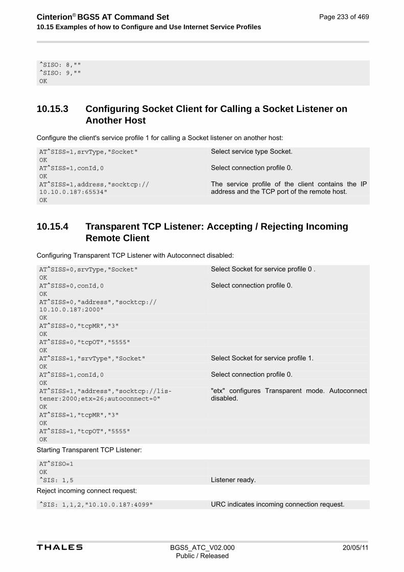
t BGS5_ATC_V02.000 20/05/11Public / Released
Cinterion® BGS5 AT Command Set 10.15 Examples of how to Configure and Use Internet Service Profiles
Page 233 of 469
10.15.3 Configuring Socket Client for Calling a Socket Listener on Another Host
Configure the client's service profile 1 for calling a Socket listener on another host:
10.15.4 Transparent TCP Listener: Accepting / Rejecting Incoming Remote Client
Configuring Transparent TCP Listener with Autoconnect disabled:
Starting Transparent TCP Listener:
Reject incoming connect request:
^SISO: 8,""^SISO: 9,""OK
AT^SISS=1,srvType,"Socket" Select service type Socket.OKAT^SISS=1,conId,0 Select connection profile 0.OKAT^SISS=1,address,"socktcp://10.10.0.187:65534"
The service profile of the client contains the IP address and the TCP port of the remote host.
OK
AT^SISS=0,srvType,"Socket" Select Socket for service profile 0 .OKAT^SISS=0,conId,0 Select connection profile 0.OKAT^SISS=0,"address","socktcp://10.10.0.187:2000"OKAT^SISS=0,"tcpMR","3"OKAT^SISS=0,"tcpOT","5555"OKAT^SISS=1,"srvType","Socket" Select Socket for service profile 1.OKAT^SISS=1,conId,0 Select connection profile 0.OKAT^SISS=1,"address","socktcp://lis-tener:2000;etx=26;autoconnect=0"
"etx" configures Transparent mode. Autoconnect disabled.
OKAT^SISS=1,"tcpMR","3"OKAT^SISS=1,"tcpOT","5555"OK
AT^SISO=1OK^SIS: 1,5 Listener ready.
^SIS: 1,1,2,"10.10.0.187:4099" URC indicates incoming connection request.

t BGS5_ATC_V02.000 20/05/11Public / Released
Cinterion® BGS5 AT Command Set 10.15 Examples of how to Configure and Use Internet Service Profiles
Page 234 of 469
Accept incoming connect request:
10.15.5 Transparent TCP Listener: Autoanswering Incoming Remote Client
Configuring Transparent Socket Listener with Autoconnect enabled.
Starting Transparent TCP Listener
AT^SISC=2 Listener rejects connect request, where 2 is the dynamically assigned service profile.
OK
^SIS: 1,1,2,"10.10.0.187:4098" URC indicates incoming connect request.AT^SISO=2 Listener accepts connect request, where 2 is the
dynamically assigned service profile.OK^SISW: 2,1 URC indicates that data transmission is possible.AT^SIST: 2 Open transparent access mode.CONNECT Service enters transparent access mode. Hello .... For further handling see examples below, e.g. Sec-
tion 10.15.10, Opening and Closing Transparent TCP Service, Section 10.15.11, Transparent TCP Client Receives Data While in AT Command Mode
AT^SISS=0,srvType,"Socket" Select Socket for service profile 0.OKAT^SISS=0,conId,0 Select connection profile 0.OKAT^SISS=0,"address","socktcp://10.10.0.187:2000"OKAT^SISS=0,"tcpMR","3"OKAT^SISS=0,"tcpOT","5555"OKAT^SISS=1,"srvType","Socket" Select Socket for service profile 1OKAT^SISS=1,conId,0 Select connection profile 0.OKAT^SISS=1,"address","socktcp://lis-tener:2000;etx=26;autoconnect=1"
"etx" configures Transparent mode. Autoconnect enabled.
OKAT^SISS=1,"tcpMR","3"OKAT^SISS=1,"tcpOT","5555"OK
AT^SISO=1OK^SIS: 1,5 Listener ready. AT^SISO=1,1^SISO: 1,"Socket",3,3,0,0,"10.10.0.187:2000","0.0.0.0:0"OK^SISW: 0,1^SISW: 1,1

t BGS5_ATC_V02.000 20/05/11Public / Released
Cinterion® BGS5 AT Command Set 10.15 Examples of how to Configure and Use Internet Service Profiles
Page 235 of 469
10.15.6 Non-Transparent Client Sends Data in Polling Mode
The example uses service profile 0 configured for Socket service and TCP.
^SIS: 1,3,1,"10.10.0.187:4100" URC indicates incoming connect request.CONNECT Service enters transparent access mode. Hello .... For further handling see examples below, e.g. Sec-
tion 10.15.10, Opening and Closing Transparent TCP Service, Section 10.15.11, Transparent TCP Client Receives Data While in AT Command Mode Type +++ to return to AT command mode (+++ not visible in example).
OKAT^SISO=1,1^SISO: 1,"Socket",8,4,0,0,"10.10.0.187:2000","10.10.0.187:4100",0OK
AT^SISO=0 The host opens service profile 0.OK Note: URC ^SISW:0,1 does not appear! The host
must poll the service state by means of AT^SISI until the service is in <srvState> "Up".
AT^SISI=0^SISI: 0,3,0,0,0,0 The service is still in <srvState> "Connecting".OKAT^SISI=0^SISI: 0,4,0,0,0,0 The service is now in <srvState> "Up" and is
ready to accept data.OKAT^SISW=0,10 The host requests to write 10 bytes.^SISW: 0,10,10 Response that 10 bytes can be sent and are unac-
knowledged.0123456789OKAT^SISW=0,10,1 The host requests to write next 10 bytes and enables
the <eodFlag>.^SISW: 0,0,10 But the service refuses the request, even the end-of-
data flag remains without effect.OKAT^SISW=0,10,1 Next try (polling).^SISW: 0,10,20 Response that the service accepts 10 bytes and this
data and the previously sent data are unacknowl-edged.
0123456789OKAT^SISW=0,0,0 Polling to request unacknowledged data.^SISW: 0,0,10 There are 10 bytes still unacknowledged.OKAT^SISI=0 Polling for <srvState> change ("Closing" ->
"Down").^SISI: 0,5,0,20,10,10 20 bytes are transfered via serial interface, 10 bytes
are acknowledged by remote peer, 10 bytes are on the way.
OKAT^SISI=0 Polling for <srvState> change ("Closing" ->
"Down").
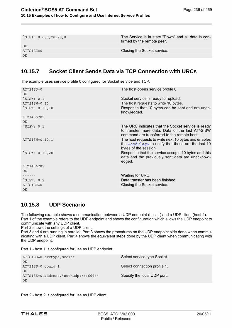
t BGS5_ATC_V02.000 20/05/11Public / Released
Cinterion® BGS5 AT Command Set 10.15 Examples of how to Configure and Use Internet Service Profiles
Page 236 of 469
10.15.7 Socket Client Sends Data via TCP Connection with URCs
The example uses service profile 0 configured for Socket service and TCP.
10.15.8 UDP Scenario
The following example shows a communication between a UDP endpoint (host 1) and a UDP client (host 2). Part 1 of the example refers to the UDP endpoint and shows the configuration which allows the UDP endpoint to communicate with any UDP client. Part 2 shows the settings of a UDP client. Part 3 and 4 are running in parallel: Part 3 shows the procedures on the UDP endpoint side done when commu-nicating with a UDP client. Part 4 shows the equivalent steps done by the UDP client when communicating with the UDP endpoint. Part 1 - host 1 is configured for use as UDP endpoint:
Part 2 - host 2 is configured for use as UDP client:
^SISI: 0,6,0,20,20,0 The Service is in state "Down" and all data is con-firmed by the remote peer.
OKAT^SISC=0 Closing the Socket service.OK
AT^SISO=0 The host opens service profile 0.OK^SISW: 0,1 Socket service is ready for upload.AT^SISW=0,10 The host requests to write 10 bytes.^SISW: 0,10,10 Response that 10 bytes can be sent and are unac-
knowledged.0123456789OK^SISW: 0,1 The URC indicates that the Socket service is ready
to transfer more data. Data of the last AT^SISW command are transferred to the remote host.
AT^SISW=0,10,1 The host requests to write next 10 bytes and enables the <eodFlag> to notify that these are the last 10 bytes of the session.
^SISW: 0,10,20 Response that the service accepts 10 bytes and this data and the previously sent data are unacknowl-edged.
0123456789OK------ Waiting for URC. ^SISW: 0,2 Data transfer has been finished. AT^SISC=0 Closing the Socket service. OK
AT^SISS=0,srvtype,socket Select service type Socket.OKAT^SISS=0,conid,1 Select connection profile 1.OKAT^SISS=0,address,"sockudp://:6666" Specify the local UDP port.OK

t BGS5_ATC_V02.000 20/05/11Public / Released
Cinterion® BGS5 AT Command Set 10.15 Examples of how to Configure and Use Internet Service Profiles
Page 237 of 469
Part 3 - host 1 opens the service and communicates with host 2:
Part 4 - host 2 opens the service and communicates with host 1:
AT^SISS=1,srvtype,socket Select service type Socket.OKAT^SISS=1,conid,1 Select connection profile 1.OKAT^SISS=1,address,"sockudp://10.10.0.219:6666"
Specify the address of host 1.
OK
AT^SISO=0 Open the service.OK^SIS: 0,5 URC indicates that host 1 is waiting (on UDP port
6666).AT^SISO=0,1^SISO: 0,"Socket",4,3,0,0,"10.10.0.219:6666","0.0.0.0:0"
Request connection status.
OK^SISR: 0,1 URC indicates that host 2 has opened the connec-
tion to host 1 and has sent some data. AT^SISR=0,100 Host 1 requests to read 100 bytes.OK^SISR: 0,22,"10.10.0.222:6561" Hello, I'm the client!
Host 1 is reading the text string received from host 2 (see part 4 of the example) and gets information about the remote client, i.e. the address of host 2.
OKAT^SISW=0,25,0,"10.10.0.222:6561" Host 1 starts sending 25 bytes to host 2.^SISW: 0,25,0 Host 1 is sending the message "Hi, I'm the UDP end-
point!" (25 bytes) to host 2. As a result, host 2 is receiving the URC "^SISR: 1,1" shown below in part 4 of the example.
OK^SISW: 0,1 URC confirms that host 1 can send data again.AT^SISC=0 Close the service.OK
AT^SISO=1 Open the service.OK^SIS: 0,5 URC indicates that host 2 can send data.AT^SISO=1,1^SISO: 1,"Socket",4,2,0,0,"10.10.0.222:6561","10.10.0.219:6666"
Request connection status.
OKAT^SISW=1,22 Host 2 starts to write 22 bytes.^SISW: 1,22,0 Host 2 is writing the message "Hello, I'm the client!"
(22 bytes). As a result, host 1 is receiving the URC "^SISR: 0,1" shown above in part 3 of this example.
OK^SISW: 1,1 URC confirms that host 2 could send data.^SISR: 1,1 URC indicates that host 2 has received data from
host 1.AT^SISR=1,100 Host 2 requests to read 100 bytes.^SISR: 1,25 Hi, I'm the UDP endpoint!
Response indicates that host 2 has received 25 characters from host 1.

t BGS5_ATC_V02.000 20/05/11Public / Released
Cinterion® BGS5 AT Command Set 10.15 Examples of how to Configure and Use Internet Service Profiles
Page 238 of 469
10.15.9 Creating Transparent TCP Socket Client
10.15.10 Opening and Closing Transparent TCP Service
OKAT^SISC=1 Close the service.OK
AT^SISS=1,srvType,"Socket" Select service type "Socket".OKAT^SISS=1,conId,1 Select connection profile 1.OKAT^SISS=1,address,"socktcp://10.10.0.110:9996;etx;timer=200"
Specify server address. Add "etx" parameter to set Transparent mode.
OK
AT^SISO=1 Open Transparent TCP service.OK^SISW: 1,1 URC indicates that Transparent TCP service is
ready.at^sist=1 Open transparent access mode.CONNECT Service is ready to send or receive data.
Client is sending data, e.g Good Morning (not visible in example).Client types +++ to return to AT command mode (+++ not visible in example).
OKat^sisi=1 Check the service state of service profile 1. ^SISI: 1,4,0,16,16,0 Service is in state "Up" (4). 0 bytes received, 16
bytes sent and acknowledged.OKAT^SISO? Check the service state of service profile 1. ^SISO: 0,""^SISO: 1,"Socket",4,2,0,16,"10.10.0.200:1024","10.10.0.108:65532"
Service is in state "Up" (4). Socket is assigned. 0 bytes received, 16 bytes sent. Local and remote IP address are assigned.
^SISO: 2,""^SISO: 3,""^SISO: 4,""^SISO: 5,""^SISO: 6,""^SISO: 7,""^SISO: 8,""^SISO: 9,""OKat^sici? Check the state of the Internet connection profile. ^SICI: 0,2,1,"10.10.0.200" Internet connection profile is in state "Up". Local IP
address is assigned.OKAT^SISC=1 Close the service. OKat^sisi=1 Check the service state of service profile 1. ^SISI: 1,2,0,0,0,0 Service profile 1 is in state "Allocated" (2).OK

t BGS5_ATC_V02.000 20/05/11Public / Released
Cinterion® BGS5 AT Command Set 10.15 Examples of how to Configure and Use Internet Service Profiles
Page 239 of 469
10.15.11 Transparent TCP Client Receives Data While in AT Command Mode
AT^SISO? Check the service state of service profile 1. ^SISO: 0,""^SISO: 1,"Socket",2,1,0,0,"0.0.0.0:0","0.0.0.0:0"
Service is in state "Allocated" (2). Socket not assigned.
^SISO: 2,""^SISO: 3,""^SISO: 4,""^SISO: 5,""^SISO: 6,""^SISO: 7,""^SISO: 8,""^SISO: 9,""OKat^sici? Check the state of the Internet connection profile. ^SICI: 0,0,0,"0.0.0.0" No Internet connection profile currently used. OK
AT^SISO=1 Open Transparent TCP service.OK^SISW: 1,1 URC indicates that Transparent TCP service is
ready.at^sist=1 Open transparent access mode.CONNECT Service is ready to send or receive data.Hello Client is reading received data.
Client types +++ to return to AT command mode (+++ not visible in example).
OK^SISR: 1,1 URC indicates that new data is available for the cli-
ent.at^sist=1 Return to transparent access mode.CONNECT Service is ready to send or receive data.Goodbye Client is reading received data.
Client types +++ to return to AT command mode (not visible in example).
OKat^sisi=1 Check the service state of service profile 1. ^SISI: 1,4,12,6,6,0 Service is in state "Up" (4). 12 bytes received, 6
bytes sent and acknowledged.OKAT^SISO? Check the service state of service profile 1. ^SISO: 0,""^SISO: 1,"Socket",4,2,12,6,"10.10.0.200:1025","10.10.0.108:65532"
Service is in state "Up" (4). Socket is assigned. 12 bytes received, 6 bytes sent. Local and remote IP address are assigned.
^SISO: 2,""^SISO: 3,""^SISO: 4,""^SISO: 5,""^SISO: 6,""^SISO: 7,""^SISO: 8,""^SISO: 9,""

t BGS5_ATC_V02.000 20/05/11Public / Released
Cinterion® BGS5 AT Command Set 10.15 Examples of how to Configure and Use Internet Service Profiles
Page 240 of 469
10.15.12 Server Disconnects While Transparent TCP Service is in Trans-parent Access Mode
OKat^sici? Check the state of the Internet connection profile. ^SICI: 0,2,1,"10.10.0.200" Internet connection profile is in state "Up". Local IP
address is assigned.OKAT^SISC=1 Close the service. OKat^sisi=1 Check the service state of service profile 1. ^SISI: 1,2,0,0,0,0 Service profile 1 is in state "Allocated" (2).OKAT^SISO? Check the service state of service profile 1. ^SISO: 0,""^SISO: 1,"Socket",2,1,0,0,"0.0.0.0:0","0.0.0.0:0"
Service is in state "Allocated" (2). Socket not assigned.
^SISO: 2,""^SISO: 3,""^SISO: 4,""^SISO: 5,""^SISO: 6,""^SISO: 7,""^SISO: 8,""^SISO: 9,""OKat^sici? Check the state of the Internet connection profile. ^SICI: 0,0,0,"0.0.0.0" No Internet connection profile currently used. OK
AT^SISO=1 Open Transparent TCP service.OK^SISW: 1,1 URC indicates that Transparent TCP service is
ready.at^sist=1 Open transparent access mode.CONNECT Service is ready to send or receive data.Good Morning NO CARRIER
Server has sent data and disconnected. Client reads data. Then client gets NO CARRIER in AT command mode.
at^sisi=1 Check the service state of service profile 1. ^SISI: 1,6,12,0,0,0 Service is in state "Down" (6). 12 bytes received.OKAT^SISO? Check the service state of service profile 1. ^SISO: 0,""^SISO: 1,"Socket",6,2,12,0,"10.10.0.200:1026","10.10.0.108:65532"
Service is in state "Down" (6). Socket is assigned. 6 bytes received. 12 bytes sent. Local and remote IP address are assigned.
^SISO: 2,""^SISO: 3,""^SISO: 4,""^SISO: 5,""^SISO: 6,""^SISO: 7,""^SISO: 8,""^SISO: 9,""

t BGS5_ATC_V02.000 20/05/11Public / Released
Cinterion® BGS5 AT Command Set 10.15 Examples of how to Configure and Use Internet Service Profiles
Page 241 of 469
10.15.13 Server Disconnects While Transparent TCP Service is in AT Command Mode and Data is Pending
OKat^sici? Check the state of the Internet connection profile. ^SICI: 0,2,1,"10.10.0.200" Internet connection profile is in state "Up". Local IP
address is assigned.OKAT^SISC=1 Close the service. OKat^sisi=1 Check the service state of service profile 1. ^SISI: 1,2,0,0,0,0 Service profile 1 is in state "Allocated" (2).OK
AT^SISO=1 Open Transparent TCP service.OK^SISW: 1,1 URC indicates that Transparent TCP service is
ready.at^sist=1 Open transparent access mode.CONNECT Service is ready to send or receive data.Good Morning Client is reading data.
Client types +++ to return to AT command mode (not visible in example).
OK^SISR: 1,1 Remote server has sent data and closed the connec-
tion (not visualized in this example). URC indicates that remaining data is available for reading.
at^sisi=1 Check service state of service profile 1.OK^SISI: 1,4,12,3,3,0 Service profile 1 is in state "Up" (4). 12 bytes
received. 3 bytes sent and acknowledged.OKAT^SISO? Check the service state of service profile 1. ^SISO: 0,""^SISO: 1,"Socket",4,2,12,3,"10.10.0.200:1027","10.10.0.108:65532"
Service is in state "Up" (4). Socket is assigned. 12 bytes received. 3 bytes sent. Local and remote IP address are assigned.
^SISO: 2,""^SISO: 3,""^SISO: 4,""^SISO: 5,""^SISO: 6,""^SISO: 7,""^SISO: 8,""^SISO: 9,""OKat^sist=1 Return to transparent access mode.CONNECT Service is ready to send or receive data.Good bye NO CARRIER
Client reads remaining data. Then client gets NO CARRIER in AT command mode.
at^sisi? Check service state of service profile 1.^SISI: 1,6,20,3,3,0 Service is in service "Down" state (6). 20 bytes
received. 3 bytes sent and acknowledged.OKAT^SISO? Check the service state of service profile 1.

t BGS5_ATC_V02.000 20/05/11Public / Released
Cinterion® BGS5 AT Command Set 10.15 Examples of how to Configure and Use Internet Service Profiles
Page 242 of 469
10.15.14 FTP Download to FFS (URC Mode)
Configure the service profile 1 for FTP:
Make an FTP connection:
^SISO: 0,""^SISO: 1,"Socket,20,3,"10.10.0.200:1027","10.10.0.108:65532"
Service is in state "Down" (6). Socket is assigned. 20 bytes received. 3 bytes sent. Local and remote IP address are assigned.
^SISO: 2,""^SISO: 3,""^SISO: 4,""^SISO: 5,""^SISO: 6,""^SISO: 7,""^SISO: 8,""^SISO: 9,""OKAT^SISC=1 Close the service.OKat^sisi=1 Check service state of service profile 1.^SISI: 1,2,0,0,0,0 Service profile 1 is in state "Allocated" (2).OKAT^SISO? Check the service state of service profile 1. ^SISO: 0,""^SISO: 1,"Socket",2,1,0,0,"0.0.0.0:0","0.0.0.0:0"
Service is in state "Allocated" (2). Socket is not assigned. Local and remote IP address not assigned.
^SISO: 2,""^SISO: 3,""^SISO: 4,""^SISO: 5,""^SISO: 6,""^SISO: 7,""^SISO: 8,""^SISO: 9,""OK
AT^SISS=1,srvType,"Ftp" Select service type FTP.OKAT^SISS=1,conId,"0" Select connection profile 0.OKAT^SISS=1,address,"ftp://ftp.heise.de/pub" Specify FTP address.OKAT^SISS=1,cmd,"fget" Select command type download.OKAT^SISS=1,user,"anonymous"OKAT^SISS=1,passwd,"[email protected]"OKAT^SISS=1,path,"file:///a:/data/" Specify target path on local FFS.OKAT^SISS=1,files,"INDEX" Specify file to be downloaded.OK
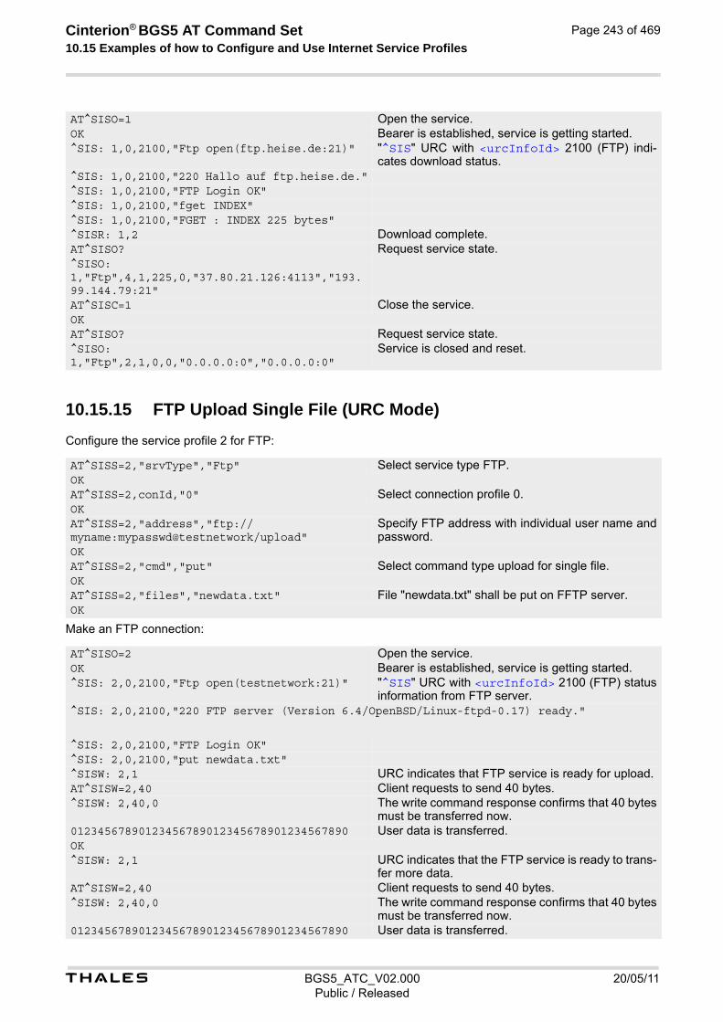
t BGS5_ATC_V02.000 20/05/11Public / Released
Cinterion® BGS5 AT Command Set 10.15 Examples of how to Configure and Use Internet Service Profiles
Page 243 of 469
10.15.15 FTP Upload Single File (URC Mode)
Configure the service profile 2 for FTP:
Make an FTP connection:
AT^SISO=1 Open the service.OK Bearer is established, service is getting started.^SIS: 1,0,2100,"Ftp open(ftp.heise.de:21)" "^SIS" URC with <urcInfoId> 2100 (FTP) indi-
cates download status. ^SIS: 1,0,2100,"220 Hallo auf ftp.heise.de."^SIS: 1,0,2100,"FTP Login OK"^SIS: 1,0,2100,"fget INDEX"^SIS: 1,0,2100,"FGET : INDEX 225 bytes"^SISR: 1,2 Download complete.AT^SISO? Request service state.^SISO: 1,"Ftp",4,1,225,0,"37.80.21.126:4113","193.99.144.79:21"AT^SISC=1 Close the service.OKAT^SISO? Request service state.^SISO: 1,"Ftp",2,1,0,0,"0.0.0.0:0","0.0.0.0:0"
Service is closed and reset.
AT^SISS=2,"srvType","Ftp" Select service type FTP.OKAT^SISS=2,conId,"0" Select connection profile 0.OKAT^SISS=2,"address","ftp://myname:mypasswd@testnetwork/upload"
Specify FTP address with individual user name and password.
OKAT^SISS=2,"cmd","put" Select command type upload for single file.OKAT^SISS=2,"files","newdata.txt" File "newdata.txt" shall be put on FFTP server.OK
AT^SISO=2 Open the service.OK Bearer is established, service is getting started.^SIS: 2,0,2100,"Ftp open(testnetwork:21)" "^SIS" URC with <urcInfoId> 2100 (FTP) status
information from FTP server.^SIS: 2,0,2100,"220 FTP server (Version 6.4/OpenBSD/Linux-ftpd-0.17) ready."
^SIS: 2,0,2100,"FTP Login OK"^SIS: 2,0,2100,"put newdata.txt"^SISW: 2,1 URC indicates that FTP service is ready for upload.AT^SISW=2,40 Client requests to send 40 bytes.^SISW: 2,40,0 The write command response confirms that 40 bytes
must be transferred now.01234567890123456789012345678901234567890 User data is transferred. OK^SISW: 2,1 URC indicates that the FTP service is ready to trans-
fer more data.AT^SISW=2,40 Client requests to send 40 bytes.^SISW: 2,40,0 The write command response confirms that 40 bytes
must be transferred now.01234567890123456789012345678901234567890 User data is transferred.
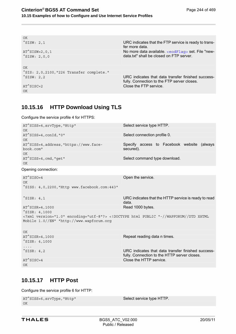
t BGS5_ATC_V02.000 20/05/11Public / Released
Cinterion® BGS5 AT Command Set 10.15 Examples of how to Configure and Use Internet Service Profiles
Page 244 of 469
10.15.16 HTTP Download Using TLS
Configure the service profile 4 for HTTPS:
Opening connection:
10.15.17 HTTP Post
Configure the service profile 6 for HTTP:
OK^SISW: 2,1 URC indicates that the FTP service is ready to trans-
fer more data.AT^SISW=2,0,1 No more data available. <eodFlag> set. File "new-
data.txt" shall be closed on FTP server.^SISW: 2,0,0
OK^SIS: 2,0,2100,"226 Transfer complete."^SISW: 2,2 URC indicates that data transfer finished success-
fully. Connection to the FTP server closes.AT^SISC=2 Close the FTP service.OK
AT^SISS=4,srvType,"Http" Select service type HTTP.OKAT^SISS=4,conId,"0" Select connection profile 0.OKAT^SISS=4,address,"https://www.face-book.com"
Specify access to Facebook website (always secured).
OKAT^SISS=4,cmd,"get" Select command type download.OK
AT^SISO=4 Open the service.OK^SISS: 4,0,2200,"Http www.facebook.com:443"
^SISR: 4,1 URC indicates that the HTTP service is ready to read data.
AT^SISR=4,1000 Read 1000 bytes.^SISR: 4,1000 <?xml version="1.0" encoding="utf-8"?> <!DOCTYPE html PUBLIC "-//WAPFORUM//DTD XHTML Mobile 1.0//EN" "http://www.wapforum.org
OKAT^SISR=4,1000 Repeat reading data n times.^SISR: 4,1000....^SISR: 4,2 URC indicates that data transfer finished success-
fully. Connection to the HTTP server closes.AT^SISC=4 Close the HTTP service.OK
AT^SISS=6,srvType,"Http" Select service type HTTP.OK

t BGS5_ATC_V02.000 20/05/11Public / Released
Cinterion® BGS5 AT Command Set 10.15 Examples of how to Configure and Use Internet Service Profiles
Page 245 of 469
Opening connection:
10.15.18 SMTP Sending Mail with Attachment from FFS
Configure the service profile 9 for FTP:
AT^SISS=6,conId,"0" Select connection profile 0.OKAT^SISS=6,"address","http://testnetwork/cgi/first.pl"
Specify URL.
OKAT^SISS=6,"user","myuser" Specify user name.OKAT^SISS=6,"passwd","mypasswd" Specify password.OKAT^SISS=6,cmd,"post" Select command type download.OKAT^SISS=6,"hcContent"," " Parameter is ignored.OKAT^SISS=6,"hcContLen","2" "hcContlen" greater than "0". Data wil be sent from
AT command interface.OK
AT^SISO=6 Open the service.OK^SISS: 6,0,2200,"Http pegasus.testnetz.sw5:80"
^SISW: 6,1 URC indicates that the HTTP service is ready to send data.
AT^SISW=6,30 Send 30 bytes.^SISW: 6,30,0OK^SISW: 6,1 URC indicates that the HTTP service is ready to
send data.AT^SISW=6,30 Send 30 bytes.^SISW: 6,30,0OK^SISW: 6,1 URC indicates that the HTTP service is ready to
send data.AT^SISW=6,0,1 Finish input by setting <eodFlag> and start HTTP
POST request.^SISW: 6,0,0OK^SISW: 6,2 URC confirms: all data sent to server.OK^SIS: 6,0,2200,"HTTP POST: http://testnetwork/cgi/first.pl"
6,0,2200,"HTTP POST Response: 200"^SISR: 6,1 Read response from server.^SISR: 6,500 Read 500 bytes.^SISR: 6,197 Reading 197 bytes.Hello ..... GoodbyeOK^SISR: 6,1 All data read.AT^SISC=6 Close the HTTP service.OK
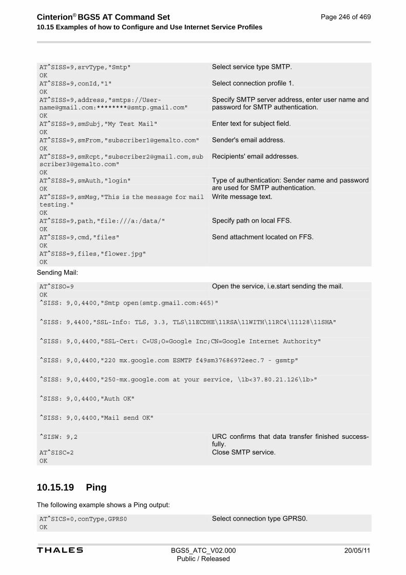
t BGS5_ATC_V02.000 20/05/11Public / Released
Cinterion® BGS5 AT Command Set 10.15 Examples of how to Configure and Use Internet Service Profiles
Page 246 of 469
Sending Mail:
10.15.19 Ping
The following example shows a Ping output:
AT^SISS=9,srvType,"Smtp" Select service type SMTP.OKAT^SISS=9,conId,"1" Select connection profile 1.OKAT^SISS=9,address,"smtps://[email protected]:********@smtp.gmail.com"
Specify SMTP server address, enter user name and password for SMTP authentication.
OKAT^SISS=9,smSubj,"My Test Mail" Enter text for subject field.OKAT^SISS=9,smFrom,"[email protected]" Sender's email address.OKAT^SISS=9,smRcpt,"[email protected],[email protected]"
Recipients' email addresses.
OKAT^SISS=9,smAuth,"login" Type of authentication: Sender name and password
are used for SMTP authentication.OKAT^SISS=9,smMsg,"This is the message for mail testing."
Write message text.
OKAT^SISS=9,path,"file:///a:/data/" Specify path on local FFS.OKAT^SISS=9,cmd,"files" Send attachment located on FFS.OKAT^SISS=9,files,"flower.jpg"OK
AT^SISO=9 Open the service, i.e.start sending the mail.OK^SISS: 9,0,4400,"Smtp open(smtp.gmail.com:465)"
^SISS: 9,4400,"SSL-Info: TLS, 3.3, TLS\11ECDHE\11RSA\11WITH\11RC4\11128\11SHA"
^SISS: 9,0,4400,"SSL-Cert: C=US;O=Google Inc;CN=Google Internet Authority"
^SISS: 9,0,4400,"220 mx.google.com ESMTP f49sm37686972eec.7 - gsmtp"
^SISS: 9,0,4400,"250-mx.google.com at your service, \1b<37.80.21.126\1b>"
^SISS: 9,0,4400,"Auth OK"
^SISS: 9,0,4400,"Mail send OK"
^SISW: 9,2 URC confirms that data transfer finished success-fully.
AT^SISC=2 Close SMTP service.OK
AT^SICS=0,conType,GPRS0 Select connection type GPRS0.OK

t BGS5_ATC_V02.000 20/05/11Public / Released
Cinterion® BGS5 AT Command Set 10.15 Examples of how to Configure and Use Internet Service Profiles
Page 247 of 469
AT^SICS=0,apn,"GPRS02.point.de"AT^SISX="Ping",0,192.168.1.2,4,2000^SISX: "Ping",1,0,"192.168.1.2",1043^SISX: "Ping",1,0,"192.168.1.2",586^SISX: "Ping",1,0,"192.168.1.2",531^SISX: "Ping",1,0,"192.168.1.2",415
^SISX: "Ping",2,1,4,4,0,0^SISX: "Ping",3,1,415,1043,643OK
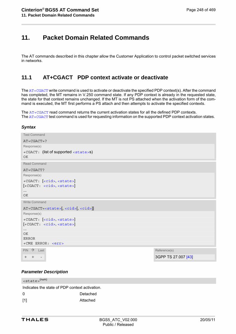
Cinterion® BGS5 AT Command Set 11. Packet Domain Related Commands
t BGS5_ATC_V02.000 20/05/11Public / Released
Page 248 of 469
11. Packet Domain Related Commands
The AT commands described in this chapter allow the Customer Application to control packet switched services in networks.
11.1 AT+CGACT PDP context activate or deactivate
The AT+CGACT write command is used to activate or deactivate the specified PDP context(s). After the command has completed, the MT remains in V.250 command state. If any PDP context is already in the requested state, the state for that context remains unchanged. If the MT is not PS attached when the activation form of the com-mand is executed, the MT first performs a PS attach and then attempts to activate the specified contexts. The AT+CGACT read command returns the current activation states for all the defined PDP contexts. The AT+CGACT test command is used for requesting information on the supported PDP context activation states.
Syntax
Parameter Description
Indicates the state of PDP context activation.
0 Detached
[1] Attached
Test Command
AT+CGACT=?Response(s)
+CGACT: (list of supported <state>s)OK
Read Command
AT+CGACT?Response(s)
+CGACT: [<cid>, <state>][+CGACT: <cid>, <state>]...OK
Write Command
AT+CGACT=<state>[, <cid>[, <cid>]]Response(s)
+CGACT: [<cid>, <state>][+CGACT: <cid>, <state>]...OKERROR+CME ERROR: <err>
PIN Last Reference(s)
+ + - 3GPP TS 27.007 [43]
<state>(num)

t BGS5_ATC_V02.000 20/05/11Public / Released
Cinterion® BGS5 AT Command Set 11.1 AT+CGACT
Page 249 of 469
Parameter specifies a particular PDP context definition (see AT+CGDCONT parameter <cid>). The parameter is used in other PDP context-related commands.
Note• If activation or deactivation of a context fails, then AT+CEER may provide further informations about the rea-
son.
<cid>(num)

t BGS5_ATC_V02.000 20/05/11Public / Released
Cinterion® BGS5 AT Command Set 11.2 AT+CGANS
Page 250 of 469
11.2 AT+CGANS Manual response to a network request for PDP con-text activation
The AT+CGANS write command requests BGS5 to respond to a network request for Packet Domain PDP context activation which has been signaled to the TE by the "RING" or "+CRING: GPRS" URC. The <response> param-eter allows the TE to accept or reject the request. This is not the same as if the MT issues a AT+CGDATA or AT+CGACT command after receiving a +CRING unso-licited result code. A AT+CGDATA or AT+CGACT does not command the MT to acknowledge the network request but rather to make a new request for context activation. The network request would be ignored.
Syntax
Parameter Description
[0] The request is rejected and BGS5 returns OK to the TE
1 Accept the request
String parameter which indicates the layer 2 protocol to be used (see AT+CGDATA command)
Numeric parameter which specifies a particular PDP context definition (see AT+CGDCONT command). Note• If <response> is 1, the following procedure is followed by BGS5:
If the <L2P> parameter value is unacceptable to BGS5, then it will return an "ERROR" or "+CME ERROR: <err>" response. Otherwise, BGS5 issues the intermediate result code CONNECT and enters V.250 online data state. A <cid> may be specified for use in the context activation request. During the PDP startup procedure BGS5 has the PDP type and the PDP address provided by the network in the Request PDP context activation message. If this is in conflict with the information provided by a specified <cid>, the command will fail. There will be no conflict, if the PDP type matches exactly and the PDP address given by the context definition for <cid> is empty or matches exactly with the address specified with the net-work PDP context activation message. The context will be activated using the values for PDP type and address provided by the network, together
Test Command
AT+CGANS=?Response(s)
+CGANS: (list of supported <response>s), (list of supported <L2P>s)OK
Write Command
AT+CGANS=[<response>[, <L2P>[, <cid>]]]Response(s)
CONNECTNO CARRIERERROR+CME ERROR: <err>
PIN Last Reference(s)
+ - + 3GPP TS 27.007 [43]
<response>(num)
<L2P>(str)
<cid>(num)
t BGS5_ATC_V02.000 20/05/11Public / Released
Cinterion® BGS5 AT Command Set 11.2 AT+CGANS
Page 251 of 469
with all other information found in the PDP context definition. If no <cid> is given or if there is no matching context definition, BGS5 will attempt to activate the context using the values for PDP type and address provided by the network. The other parameters will be set to their default values (see AT+CGDCONT). If activation is successful, data transfer will proceed. After data transfer is complete, and the layer 2 protocol termination procedure has completed successfully, the V.250 command state is reentered and BGS5 returns the final result code OK. In the event of an erroneous termination or a failure to start up, the V.250 command state is re-entered and BGS5 returns the final result code NO CARRIER, or if enabled, "+CME ERROR: <err>". Attach, activate and other errors may be reported. It is also an error to issue the AT+CGANS command when there is no pending network request. The command can be used in both normal and modem compatibility modes.

t BGS5_ATC_V02.000 20/05/11Public / Released
Cinterion® BGS5 AT Command Set 11.3 AT+CGATT
Page 252 of 469
11.3 AT+CGATT PS attach or detach
The AT+CGATT write command is used to attach the MT to, or detach the MT from the Packet Domain service. After the command has completed, the MT remains in V.250 command state. If the MT is already in the requested state, the command is ignored and the OK response is returned. Any active PDP contexts will be automatically deactivated when the attachment state changes to detached. The AT+CGATT read command returns the current Packet Domain service state. The AT+CGATT test command is used for requesting information on the supported Packet Domain service states.
Syntax
Parameter Description
Indicates the state of Packet Domain attachment. The parameter is global for all interfaces.
0(P) Detached
[1] Attached
Test Command
AT+CGATT=?Response(s)
+CGATT: (list of supported <state>s)OK
Read Command
AT+CGATT?Response(s)
+CGATT: <state>OK
Write Command
AT+CGATT=[<state>]Response(s)
OKERROR+CME ERROR: <err>
PIN Last Reference(s)
+ - - 3GPP TS 27.007 [43]
<state>(num)

t BGS5_ATC_V02.000 20/05/11Public / Released
Cinterion® BGS5 AT Command Set 11.4 AT+CGAUTO
Page 253 of 469
11.4 AT+CGAUTO Automatic response to Network Request for PDP Context Activation
The AT+CGAUTO write command enables or disables an automatic positive or negative response (auto-answer) to the receipt of a NW initiated Request PDP Context Activation message in GSM. It also provides control over the use of the V.250 basic commands ATS0, ATA and ATH for handling network initiated requests. For details refer to sections ATS0, ATA, ATH in Chapter 11., Packet Domain Related Commands.
Syntax
Parameter Description
0 Disable automatic response for NW-initiated Requests for PDP Context Acti-vation. Packet Domain network requests are manually accepted or rejected by the AT+CGANS command.
1 Enable automatic response for NW-initiated Requests for PDP Context Activa-tion. Packet Domain requests are automatically accepted according to the description below.
2 Modem compatibility mode. Packet Domain only.
3(P) Modem compatibility mode. The automatic acceptance of network initiated Packet Domain connections and incoming circuit switched calls is controlled by the ATS0 command. Manual control uses the commands ATA and ATH or AT+CGANS to accept or reject Packet Domain network requests or incoming circuit switched connections.
4 Turn on automatic negative response for Packet Domain only.
Test Command
AT+CGAUTO=?Response(s)
+CGAUTO: (list of supported <n>s)OK
Read Command
AT+CGAUTO?Response(s)
+CGAUTO: <n>OK
Write Command
AT+CGAUTO=[<n>]Response(s)
OKERROR+CME ERROR: <err>
PIN Last Reference(s)
+ - - 3GPP TS 27.007 [43]
<n>(num)

t BGS5_ATC_V02.000 20/05/11Public / Released
Cinterion® BGS5 AT Command Set 11.4 AT+CGAUTO
Page 254 of 469
Notes• When the AT+CGAUTO=0 command is received, the MT will not perform a PS detach if it is attached. Subse-
quently, when the MT announces a network request for PDP context activation by issuing the "RING" URC or "+CRING: GPRS" URC, the TE may manually accept or reject the request by issuing the AT+CGANS command or may simply ignore the network request.
• When the AT+CGAUTO=1 command is received, the MT will attempt to perform a PS attach if it is not yet attached. Failure will result in ERROR or, if enabled +CME ERROR being returned to the TE. Subsequently, the MT announces a network request for PDP context activation by issuing the "RING" URC or "+CRING: GPRS" URC to the TE, followed by the intermediate result code CONNECT. The MT then enters V.250 online data state and follows the same procedure as it would after having received a +CGANS=1 with no <L2P> or <cid> values specified.
• If a network request for PDP context activation is answered automatically and if another AT command is issued at the same time on the same interface, then this AT command is not executed. Any response belongs to the automatic context activation procedure. If the AT command which caused the collision was a circuit switched data call, the CONNECT response does not belong to this data call but to the PS. This can be detected if ATX is not set to 0. CS data call will issue CONNECT <text>, PS will issue CONNECT only.
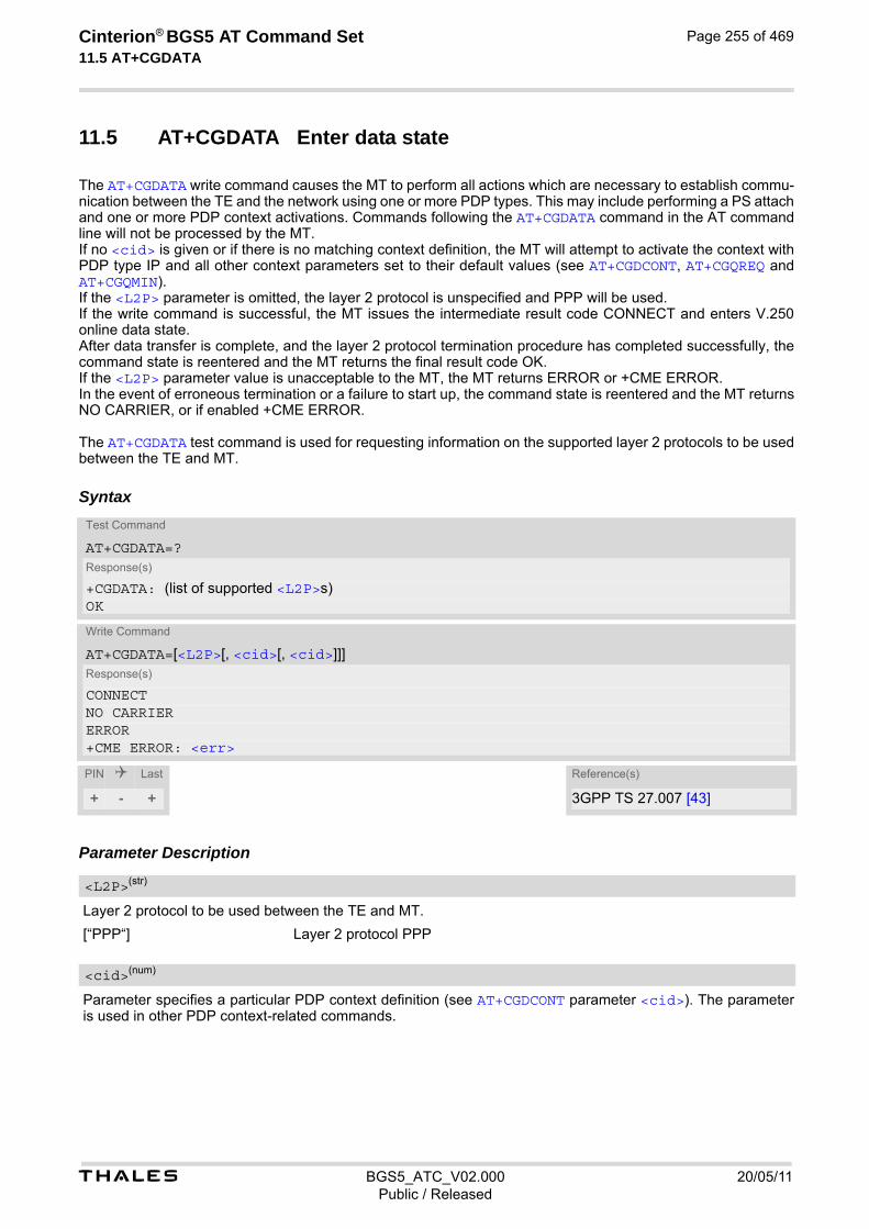
t BGS5_ATC_V02.000 20/05/11Public / Released
Cinterion® BGS5 AT Command Set 11.5 AT+CGDATA
Page 255 of 469
11.5 AT+CGDATA Enter data state
The AT+CGDATA write command causes the MT to perform all actions which are necessary to establish commu-nication between the TE and the network using one or more PDP types. This may include performing a PS attach and one or more PDP context activations. Commands following the AT+CGDATA command in the AT command line will not be processed by the MT. If no <cid> is given or if there is no matching context definition, the MT will attempt to activate the context with PDP type IP and all other context parameters set to their default values (see AT+CGDCONT, AT+CGQREQ and AT+CGQMIN). If the <L2P> parameter is omitted, the layer 2 protocol is unspecified and PPP will be used. If the write command is successful, the MT issues the intermediate result code CONNECT and enters V.250 online data state. After data transfer is complete, and the layer 2 protocol termination procedure has completed successfully, the command state is reentered and the MT returns the final result code OK. If the <L2P> parameter value is unacceptable to the MT, the MT returns ERROR or +CME ERROR. In the event of erroneous termination or a failure to start up, the command state is reentered and the MT returns NO CARRIER, or if enabled +CME ERROR. The AT+CGDATA test command is used for requesting information on the supported layer 2 protocols to be used between the TE and MT.
Syntax
Parameter Description
Layer 2 protocol to be used between the TE and MT.
[“PPP“] Layer 2 protocol PPP
Parameter specifies a particular PDP context definition (see AT+CGDCONT parameter <cid>). The parameter is used in other PDP context-related commands.
Test Command
AT+CGDATA=?Response(s)
+CGDATA: (list of supported <L2P>s)OK
Write Command
AT+CGDATA=[<L2P>[, <cid>[, <cid>]]]Response(s)
CONNECTNO CARRIERERROR+CME ERROR: <err>
PIN Last Reference(s)
+ - + 3GPP TS 27.007 [43]
<L2P>(str)
<cid>(num)
t BGS5_ATC_V02.000 20/05/11Public / Released
Cinterion® BGS5 AT Command Set 11.5 AT+CGDATA
Page 256 of 469
11.5.1 Automatic deactivation of PDP context during dial-up PPP
When using the AT+CGDATA write command or ATD*99# the MT issues the intermediate result code CONNECT and enters V.250ter online data state. In V.250 online data state, first some LCP protocol exchange between MT and TE is performed to set up the PPP link. After successfully establishing the PPP link, the MT performs the PDP context activation procedure if the context is not already activated. As a result, the MT is in a "PDP context activated" state within the PLMN, the PPP link is established on the mobile side and the mobile is ready for IP data transfer. If the TE wants to close the LCP link the MT may perform an LCP termination request procedure on PPP level. After this LCP termination procedure the MT deactivates the PDP context automatically and the MT returns to V.250 command mode and issues the final result code NO CARRIER. During the implicit PDP context deactivation procedure after LCP termination the TE may change into V.250 command state (e.g. by using +++ or by toggling DTR if AT&D is set to 1) before the result NO CARRIER occurs. In this case the application should not try to deactivate the PDP context by using the commands AT+CGACT or ATH. If DTR is configured to disconnect data connections (AT&D2), then the application should not toggle DTR during the implicit PDP context deactivation and before "NO CARRIER" is received.
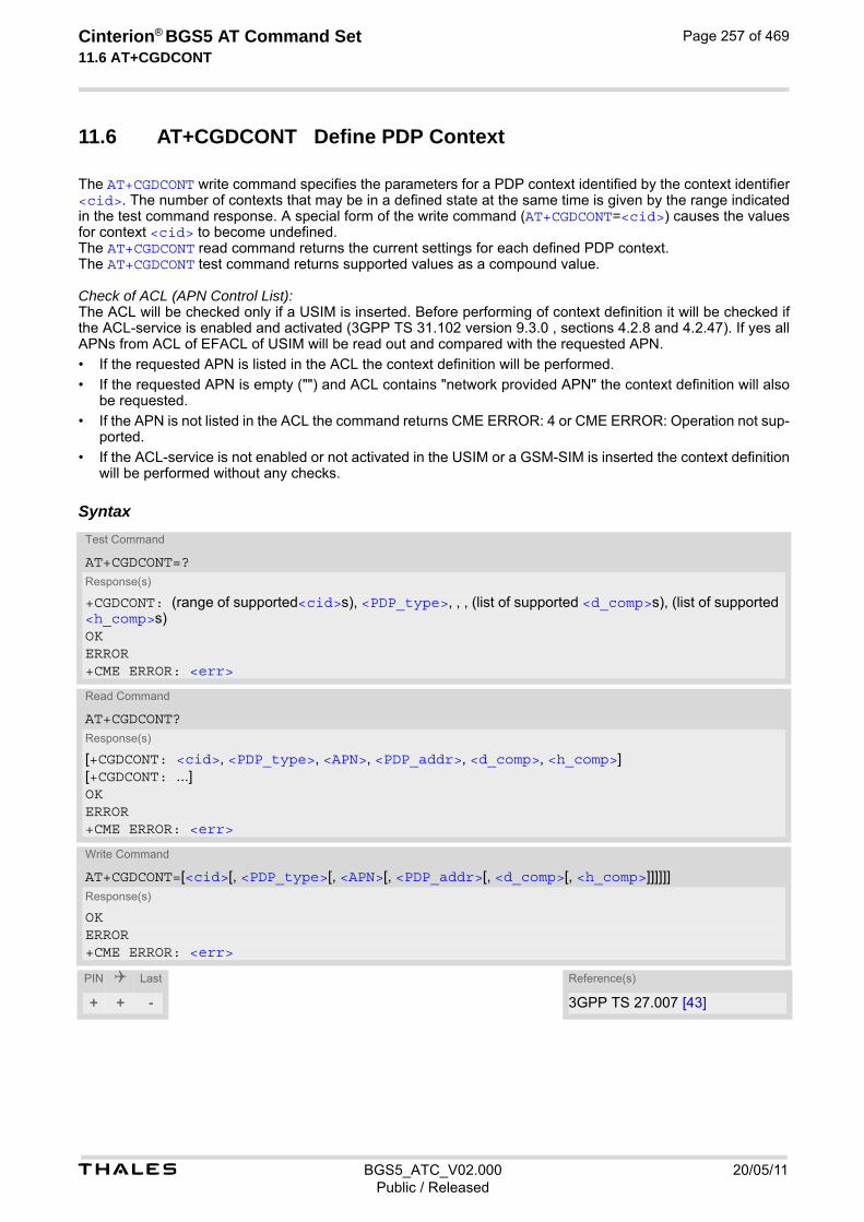
t BGS5_ATC_V02.000 20/05/11Public / Released
Cinterion® BGS5 AT Command Set 11.6 AT+CGDCONT
Page 257 of 469
11.6 AT+CGDCONT Define PDP Context
The AT+CGDCONT write command specifies the parameters for a PDP context identified by the context identifier <cid>. The number of contexts that may be in a defined state at the same time is given by the range indicated in the test command response. A special form of the write command (AT+CGDCONT=<cid>) causes the values for context <cid> to become undefined. The AT+CGDCONT read command returns the current settings for each defined PDP context. The AT+CGDCONT test command returns supported values as a compound value. Check of ACL (APN Control List): The ACL will be checked only if a USIM is inserted. Before performing of context definition it will be checked if the ACL-service is enabled and activated (3GPP TS 31.102 version 9.3.0 , sections 4.2.8 and 4.2.47). If yes all APNs from ACL of EFACL of USIM will be read out and compared with the requested APN.
• If the requested APN is listed in the ACL the context definition will be performed.
• If the requested APN is empty ("") and ACL contains "network provided APN" the context definition will also be requested.
• If the APN is not listed in the ACL the command returns CME ERROR: 4 or CME ERROR: Operation not sup-ported.
• If the ACL-service is not enabled or not activated in the USIM or a GSM-SIM is inserted the context definition will be performed without any checks.
Syntax
Test Command
AT+CGDCONT=?Response(s)
+CGDCONT: (range of supported<cid>s), <PDP_type>, , , (list of supported <d_comp>s), (list of supported <h_comp>s)OKERROR+CME ERROR: <err>
Read Command
AT+CGDCONT?Response(s)
[+CGDCONT: <cid>, <PDP_type>, <APN>, <PDP_addr>, <d_comp>, <h_comp>][+CGDCONT: ...]OKERROR+CME ERROR: <err>
Write Command
AT+CGDCONT=[<cid>[, <PDP_type>[, <APN>[, <PDP_addr>[, <d_comp>[, <h_comp>]]]]]]Response(s)
OKERROR+CME ERROR: <err>
PIN Last Reference(s)
+ + - 3GPP TS 27.007 [43]

t BGS5_ATC_V02.000 20/05/11Public / Released
Cinterion® BGS5 AT Command Set 11.6 AT+CGDCONT
Page 258 of 469
Parameter Description
PDP Context Identifier
Parameter specifies a particular PDP context definition. The parameter is used in other PDP context-related commands. The range of the permitted values for <cid> is given by the AT+CGDCONT test command.
1...11
Packet Data Protocol type
Specifies the type of the packet data protocol.
“IP“ Internet Protocol (IETF STD 5)
Access Point Name
The logical name that is used to select the GGSN or the external packet data network. If the value is null or omitted, then the subscription value will be requested.
Packet Data Protocol address
Identifies the MT in the address space applicable to PDP (e.g. IP V4 address for PDP type IP). If the value is null or omitted, then a value may be provided by the TE during the PDP startup procedure or, failing that, a dynamic address will be requested. The read command will continue to return the null string even if an address has been allocated during the PDP startup procedure. The allocated address may be read using AT+CGPADDR.
Data Compression
Controls the PDP data compression (applicable for Subnetwork Dependent Convergence Protocol (SNDCP) only) 3GPP TS 44.065
[0] off
Header Compression
Controls the PDP header compression 3GPP TS 44.065, 3GPP TS 25.323
[0] off
2 RFC1144
3 RFC2507 Note• The ME supports PDP type IP only.
<cid>(num)(NV)
<PDP_type>(str)(NV)
<APN>(str)(NV)
<PDP_addr>(str)(NV)
<d_comp>(num)(NV)
<h_comp>(num)(NV)

t BGS5_ATC_V02.000 20/05/11Public / Released
Cinterion® BGS5 AT Command Set 11.7 AT+CGCMOD
Page 259 of 469
11.7 AT+CGCMOD PDP Context Modify
The AT+CGCMOD write command can be used to modify the specified PDP context(s) with respect to QoS pro-files. If no <cid>s are specified then all active contexts will be modified, provided the used mobile network sup-ports that form of context modification. If modification of a context fails, then AT+CEER may provide further informations about the reason. The AT+CGCMOD test command returns a list of <cid>s associated with active contexts which could be modified.
Syntax
Parameter Description
Parameter specifies a particular PDP context definition (see AT+CGDCONT parameter <cid>).
Test Command
AT+CGCMOD=?Response(s)
+CGCMOD: (list of <cid>s associated with active contexts)OKERROR+CME ERROR: <err>
Exec Command
AT+CGCMODResponse(s)
OKERROR+CME ERROR: <err>
Write Command
AT+CGCMOD=<cid>[, <cid>[, ...]]Response(s)
OKERROR+CME ERROR: <err>
PIN Last Reference(s)
+ - - 3GPP TS 27.007 [43]
<cid>(num)

t BGS5_ATC_V02.000 20/05/11Public / Released
Cinterion® BGS5 AT Command Set 11.8 AT+CGEREP
Page 260 of 469
11.8 AT+CGEREP Packet Domain Event Reporting
The AT+CGEREP write command enables or disables sending of unsolicited result codes, +CGEV URCs from MT to TE in the case of certain events occurring in the Packet Domain MT or the network. Parameter <mode> controls the processing of unsolicited result codes specified within this command. <bfr> controls the effect on buffered codes when <mode> 1 or 2 is entered. If a setting is not supported by the MT, ERROR or +CME ERROR: is returned. The AT+CGEREP read command returns the current <mode> and buffer settings. The AT+CGEREP test command returns the modes and buffer settings supported by the MT as compound values.
Syntax
Unsolicited Result Codes
URC 1
+CGEV: NW DEACT <PDP_type>, <PDP_addr>[, <cid>]
The network has forced a context deactivation. The <cid> that was used to activate the context is provided if known to the MT.
URC 2
+CGEV: ME DEACT <PDP_type>, <PDP_addr>[, <cid>]
The ME has forced a context deactivation. The <cid> that was used to activate the context is provided if known to the MT.
URC 3
+CGEV: NW DETACH
The network has forced a PS detach. This implies that all active contexts have been deactivated. These are not reported separately.
Test Command
AT+CGEREP=?Response(s)
+CGEREP: (list of supported <mode>s), (list of supported <bfr>s)OK
Read Command
AT+CGEREP?Response(s)
+CGEREP: <mode>, <bfr>OK
Write Command
AT+CGEREP=[<mode>[, <bfr>]]Response(s)
OKERROR+CME ERROR: <err>
PIN Last Reference(s)
+ + - 3GPP TS 27.007 [43]

t BGS5_ATC_V02.000 20/05/11Public / Released
Cinterion® BGS5 AT Command Set 11.8 AT+CGEREP
Page 261 of 469
URC 4
+CGEV: ME DETACH
The ME has forced a PS detach. This implies that all active contexts have been deactivated. These are not reported separately.
Parameter Description
0(P) Buffer unsolicited result codes in the MT. If MT result code buffer is full, the old-est ones will be discarded. No codes are forwarded to the TE.
1 Discard unsolicited result codes when MT TE link is reserved (e.g. AT com-mand port is in use, e.g. in online mode or in waiting state due to AT command processing); otherwise forward them directly to the TE.
2 Buffer unsolicited result codes in the MT when MT TE link is reserved (AT com-mand port is in use, e.g. in online mode or in waiting state due to AT command processing) and flush them to the TE when MT TE link becomes available; oth-erwise forward them directly to the TE. If MT result code buffer is full, the oldest URCs will be discarded.
0 MT buffer of unsolicited result codes defined within this command is cleared when <mode> 1 or 2 is entered
1 MT buffer of unsolicited result codes defined within this command is flushed to the TE when <mode> 1 or 2 is entered (OK response will be given before flush-ing the codes). Buffer is empty afterwards.
<mode>(num)
<bfr>(num)

t BGS5_ATC_V02.000 20/05/11Public / Released
Cinterion® BGS5 AT Command Set 11.9 AT+CGPADDR
Page 262 of 469
11.9 AT+CGPADDR Show PDP address
The AT+CGPADDR write command returns a list of PDP addresses for the specified context identifiers. If a context is not defined, then no output line is generated for it. If no <cid> is specified, the addresses for all defined con-texts are returned. The AT+CGPADDR test command returns a list of defined <cid>s.
Syntax
Parameter Description
A numeric parameter which specifies a particular PDP context definition (see AT+CGDCONT command).
A string that identifies the MT in the address space applicable to the PDP. The address may be static or dynamic. For a static address, it will be the one set by AT+CGDCONT, when the context was defined. For a dynamic address it will be the one assigned during the last PDP context activation that used the context definition referred to by <cid>.
Test Command
AT+CGPADDR=?Response(s)
[+CGPADDR: (list of defined <cid>s)]OK
Write Command
AT+CGPADDR=[<cid>[,<cid>]]Response(s)
[+CGPADDR: <cid>, <PDP_address>][+CGPADDR: <cid>, <PDP_address>]OKERROR+CME ERROR: <err>
PIN Last Reference(s)
+ + - 3GPP TS 27.007 [43]
<cid>(num)
<PDP_address>(str)

t BGS5_ATC_V02.000 20/05/11Public / Released
Cinterion® BGS5 AT Command Set 11.10 AT+CGQMIN
Page 263 of 469
11.10 AT+CGQMIN Quality of Service Profile (Minimum acceptable)
This AT+CGQMIN command allows the TE to specify a minimum acceptable profile which is checked by the MT against the negotiated profile returned in the Activate PDP Context Accept message. The AT+CGQMIN write command specifies a profile for the context identified by the (local) context identification parameter, <cid>. A special form of the write command, AT+CGQMIN= <cid> causes the minimum acceptable profile for context number <cid> to become undefined. In this case no check is made against the negotiated profile. The AT+CGQMIN test command returns values supported as a compound value. If the MT supports several PDP types, the parameter value ranges for each PDP type are returned on a separate line. The AT+CGQMIN read command returns the current settings for each defined context. If no minimum profile was explicitly specified for a context, simply OK will be returned, but default values will be used for that context.
Syntax
Parameter Description
Parameter specifies a particular PDP context definition (see AT+CGDCONT parameter <cid>). The parameter is used in other PDP context-related commands.
Test Command
AT+CGQMIN=?Response(s)
+CGQMIN: <PDP_type>, (list of supported <precedence>s), (list of supported <delay>s), (list of supported <reliability>s), (list of supported <peak>s), (list of supported <mean>s)[+CGQMIN: <PDP_type>, (list of supported <precedence>s), (list of supported <delay>s), (list of supported <reliability>s), (list of supported <peak>s), (list of supported <mean>s)][+CGQMIN: ...]OKERROR+CME ERROR: <err>
Read Command
AT+CGQMIN?Response(s)
[+CGQMIN: <cid>, <precedence>, <delay>, <reliability>, <peak>, <mean>][+CGQMIN: ...]OKERROR+CME ERROR: <err>
Write Command
AT+CGQMIN=[<cid>[, <precedence>[, <delay>[, <reliability>[, <peak>[, <mean>]]]]]]Response(s)
OKERROR+CME ERROR: <err>
PIN Last Reference(s)
+ + - 3GPP TS 27.007 [43]
<cid>(num)(NV)

t BGS5_ATC_V02.000 20/05/11Public / Released
Cinterion® BGS5 AT Command Set 11.10 AT+CGQMIN
Page 264 of 469
Precedence class
[0] network subscribed value
1 High Priority Service commitments shall be maintained ahead of precedence classes 2 and 3
2 Normal priority Service commitments shall be maintained ahead of precedence class 3
3 Low priority Service commitments shall be maintained
Delay class
The delay parameter defines the end-to-end transfer delay incurred in the transmission of SDUs through the GPRS network(s).
[0] network subscribed value
1..4 SDU size: 128 octets:
SDU size: 1024 octets:
Reliability class
[0] network subscribed value
1 Reliability class 1 was removed in 3GPP TS 23.107 [36] v6.1.0, and is auto-matically mapped to reliability class 2.
2 Non real-time traffic, error-sensitive application that can cope with infrequent data loss
3 Non real-time traffic, error-sensitive application that can cope with data loss, GMM/SM, and SMS
4 Real-time traffic, error-sensitive application that can cope with data loss
5 Real-time traffic, error non-sensitive application that can cope with data loss
<precedence>(num)(NV)
<delay>(num)(NV)
Delay Class Mean Transfer Delay 95 percentile
1 (Predictive) <0.5 <1.5
2 (Predictive) <5 <25
3 (Predictive) <50 <250
4 (Best Effort) Unspecified
Delay Class Mean Transfer Delay 95 percentile
1 (Predictive) <0.5 <1.5
2 (Predictive) <5 <25
3 (Predictive) <50 <250
4 (Best Effort) Unspecified
<reliability>(num)(NV)

t BGS5_ATC_V02.000 20/05/11Public / Released
Cinterion® BGS5 AT Command Set 11.10 AT+CGQMIN
Page 265 of 469
Peak throughput class (in octets per second).
[0] network subscribed value
1 Up to 1 000 (8 kbit/s).
2 Up to 2 000 (16 kbit/s).
3 Up to 4 000 (32 kbit/s).
4 Up to 8 000 (64 kbit/s).
5 Up to 16 000 (128 kbit/s).
6 Up to 32 000 (256 kbit/s).
7 Up to 64 000 (512 kbit/s).
8 Up to 128 000 (1024 kbit/s).
9 Up to 256 000 (2048 kbit/s).
Mean throughput class(in octets per hour).
[0] network subscribed value
1 100 (~0.22 bit/s)
2 200 (~0.44 bit/s)
3 500 (~1.11 bit/s)
4 1 000 (~2.2 bit/s)
5 2 000 (~4.4 bit/s)
6 5 000 (~11.1 bit/s)
7 10 000 (~22 bit/s)
8 20 000 (~44 bit/s)
9 50 000 (~111 bit/s)
10 100 000 (~0.22 kbit/s)
11 200 000(~0.44 kbit/s)
12 500 000(~1.11 kbit/s)
13 1 000 000 (~2.2 kbit/s)
14 2 000 000 (~4.4 kbit/s)
15 5 000 000 (~11.1 kbit/s)
16 10 000 000 (~22 kbit/s)
17 20 000 000 (~44 kbit/s)
18 50 000 000 (~111 kbit/s)
31 best effort
Packet Data Protocol Type
“IP“
<peak>(num)(NV)
<mean>(num)(NV)
<PDP_type>(str)
t BGS5_ATC_V02.000 20/05/11Public / Released
Cinterion® BGS5 AT Command Set 11.10 AT+CGQMIN
Page 266 of 469
Notes• If parameters are not defined, the parameter default values depend on the HLR-stored subscribed default val-
ues.
• Definitions of parameters can be found in 3GPP TS 22.060 [25] and 3GPP TS 23.060 [26] paragraph 15.2 "Quality of Service Profile".
• If some of the QoS parameters are omitted, they will keep their current value (or the default value if not spec-ified so far).

t BGS5_ATC_V02.000 20/05/11Public / Released
Cinterion® BGS5 AT Command Set 11.11 AT+CGQREQ
Page 267 of 469
11.11 AT+CGQREQ Quality of Service Profile (Requested)
The AT+CGQREQ command allows the TE to specify a Quality of Service Profile that is used when the MT sends an Activate PDP Context Request message to the network. The AT+CGQREQ write command specifies a profile for the context identified by the (local) context identification parameter, <cid>. A special form of the write command, +CGQREQ=<cid> causes the requested profile for context number <cid> to become undefined. The AT+CGQREQ test command returns values supported as a compound value. If the MT supports several PDP types, the parameter value ranges for each PDP type are returned on a separate line. The AT+CGQREQ read command returns the current settings for each defined context. If no requested profile was explicitly specified for a context, simply OK will be returned, but default values will be used for that context.
Syntax
Parameter Description
Parameter specifies a particular PDP context definition (see AT+CGDCONT parameter <cid>). The parameter is used in other PDP context-related commands.
Test Command
AT+CGQREQ=?Response(s)
+CGQREQ: <PDP_type>, (list of supported <precedence>s), (list of supported <delay>s), (list of supported <reliability>s), (list of supported <peak>s), (list of supported <mean>s)[+CGQREQ: <PDP_type>, (list of supported <precedence>s), (list of supported <delay>s), (list of supported <reliability>s), (list of supported <peak>s), (list of supported <mean>s)][+CGQREQ: ...]OKERROR+CME ERROR: <err>
Read Command
AT+CGQREQ?Response(s)
[+CGQREQ: <cid>, <precedence>, <delay>, <reliability>, <peak>, <mean>][+CGQREQ: ...]OKERROR+CME ERROR: <err>
Write Command
AT+CGQREQ=<cid>[, <precedence>[, <delay>[, <reliability>[, <peak>[, <mean>]]]]]Response(s)
OKERROR+CME ERROR: <err>
PIN Last Reference(s)
+ + - 3GPP TS 27.007 [43]
<cid>(num)(NV)
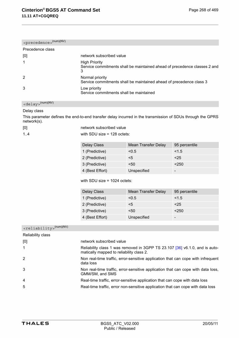
t BGS5_ATC_V02.000 20/05/11Public / Released
Cinterion® BGS5 AT Command Set 11.11 AT+CGQREQ
Page 268 of 469
Precedence class
[0] network subscribed value
1 High Priority Service commitments shall be maintained ahead of precedence classes 2 and 3
2 Normal priority Service commitments shall be maintained ahead of precedence class 3
3 Low priority Service commitments shall be maintained
Delay class
This parameter defines the end-to-end transfer delay incurred in the transmission of SDUs through the GPRS network(s).
[0] network subscribed value
1..4 with SDU size = 128 octets:
with SDU size = 1024 octets:
Reliability class
[0] network subscribed value
1 Reliability class 1 was removed in 3GPP TS 23.107 [36] v6.1.0, and is auto-matically mapped to reliability class 2.
2 Non real-time traffic, error-sensitive application that can cope with infrequent data loss
3 Non real-time traffic, error-sensitive application that can cope with data loss, GMM/SM, and SMS
4 Real-time traffic, error-sensitive application that can cope with data loss
5 Real-time traffic, error non-sensitive application that can cope with data loss
<precedence>(num)(NV)
<delay>(num)(NV)
Delay Class Mean Transfer Delay 95 percentile
1 (Predictive) <0.5 <1.5
2 (Predictive) <5 <25
3 (Predictive) <50 <250
4 (Best Effort) Unspecified -
Delay Class Mean Transfer Delay 95 percentile
1 (Predictive) <0.5 <1.5
2 (Predictive) <5 <25
3 (Predictive) <50 <250
4 (Best Effort) Unspecified -
<reliability>(num)(NV)
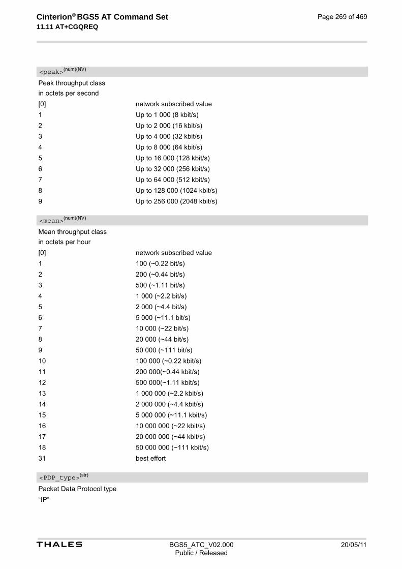
t BGS5_ATC_V02.000 20/05/11Public / Released
Cinterion® BGS5 AT Command Set 11.11 AT+CGQREQ
Page 269 of 469
Peak throughput class
in octets per second
[0] network subscribed value
1 Up to 1 000 (8 kbit/s)
2 Up to 2 000 (16 kbit/s)
3 Up to 4 000 (32 kbit/s)
4 Up to 8 000 (64 kbit/s)
5 Up to 16 000 (128 kbit/s)
6 Up to 32 000 (256 kbit/s)
7 Up to 64 000 (512 kbit/s)
8 Up to 128 000 (1024 kbit/s)
9 Up to 256 000 (2048 kbit/s)
Mean throughput class
in octets per hour
[0] network subscribed value
1 100 (~0.22 bit/s)
2 200 (~0.44 bit/s)
3 500 (~1.11 bit/s)
4 1 000 (~2.2 bit/s)
5 2 000 (~4.4 bit/s)
6 5 000 (~11.1 bit/s)
7 10 000 (~22 bit/s)
8 20 000 (~44 bit/s)
9 50 000 (~111 bit/s)
10 100 000 (~0.22 kbit/s)
11 200 000(~0.44 kbit/s)
12 500 000(~1.11 kbit/s)
13 1 000 000 (~2.2 kbit/s)
14 2 000 000 (~4.4 kbit/s)
15 5 000 000 (~11.1 kbit/s)
16 10 000 000 (~22 kbit/s)
17 20 000 000 (~44 kbit/s)
18 50 000 000 (~111 kbit/s)
31 best effort
Packet Data Protocol type
“IP“
<peak>(num)(NV)
<mean>(num)(NV)
<PDP_type>(str)
t BGS5_ATC_V02.000 20/05/11Public / Released
Cinterion® BGS5 AT Command Set 11.11 AT+CGQREQ
Page 270 of 469
Notes• If parameters are not defined, the parameter default values depend on the HLR-stored subscribed default val-
ues.
• Definitions of parameters can be found in 3GPP TS 22.060 [25] and 3GPP TS 23.060 [26] paragraph 15.2 "Quality of Service Profile".
• If some of the QoS parameters are omitted, they will keep their current value (or the default value if not spec-ified so far).

t BGS5_ATC_V02.000 20/05/11Public / Released
Cinterion® BGS5 AT Command Set 11.12 AT+CGREG
Page 271 of 469
11.12 AT+CGREG Packet Domain Network Registration Status
AT+CGREG write command enables presentation of URC "+CGREG: <stat>" when <n>=1 and ME's Packet Domain network registration status in GERAN changes, or URC "+CGREG: <stat>[, <lac>, <ci>]" when <n>=2 and the current network cell in GERAN changes. AT+CGREG read command queries the current URC presentation status and <stat> which shows whether the network has currently indicated the registration of the ME. Location information elements <lac> and <ci> are returned only if <n>=2 and ME is registered to the network.
Syntax
Unsolicited Result Codes
URC 1
+CGREG: <stat>
Indicates a change in the ME's Packet Domain network registration status.
URC 2
+CGREG: <stat>[, <lac>, <ci>]
Indicates a change in the ME's Packet Domain network registration status or a change of the network cell including location information.
Parameter Description
0(P) Disable network registration unsolicited result code
1 Enable network registration URC "+CGREG: <stat>"
2 Enable network registration URC "+CGREG: <stat>[, <lac>, <ci>]"
Test Command
AT+CGREG=?Response(s)
+CGREG: (list of supported <n>s)OK
Read Command
AT+CGREG?Response(s)
+CGREG: <n>, <stat>[, <lac>, <ci>]OK
Write Command
AT+CGREG=[<n>]Response(s)
OKERROR+CME ERROR: <err>
PIN Last Reference(s)
+ + - 3GPP TS 27.007 [43]
<n>(num)
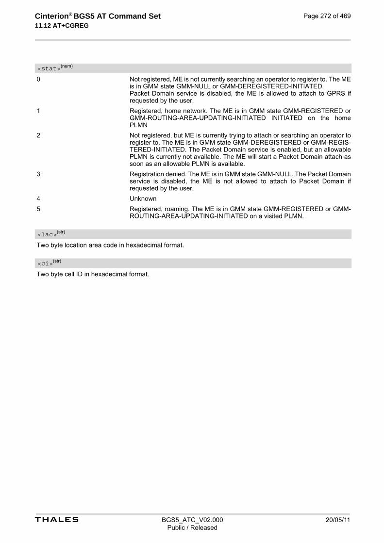
t BGS5_ATC_V02.000 20/05/11Public / Released
Cinterion® BGS5 AT Command Set 11.12 AT+CGREG
Page 272 of 469
0 Not registered, ME is not currently searching an operator to register to. The ME is in GMM state GMM-NULL or GMM-DEREGISTERED-INITIATED. Packet Domain service is disabled, the ME is allowed to attach to GPRS if requested by the user.
1 Registered, home network. The ME is in GMM state GMM-REGISTERED or GMM-ROUTING-AREA-UPDATING-INITIATED INITIATED on the home PLMN
2 Not registered, but ME is currently trying to attach or searching an operator to register to. The ME is in GMM state GMM-DEREGISTERED or GMM-REGIS-TERED-INITIATED. The Packet Domain service is enabled, but an allowable PLMN is currently not available. The ME will start a Packet Domain attach as soon as an allowable PLMN is available.
3 Registration denied. The ME is in GMM state GMM-NULL. The Packet Domain service is disabled, the ME is not allowed to attach to Packet Domain if requested by the user.
4 Unknown
5 Registered, roaming. The ME is in GMM state GMM-REGISTERED or GMM-ROUTING-AREA-UPDATING-INITIATED on a visited PLMN.
Two byte location area code in hexadecimal format.
Two byte cell ID in hexadecimal format.
<stat>(num)
<lac>(str)
<ci>(str)

t BGS5_ATC_V02.000 20/05/11Public / Released
Cinterion® BGS5 AT Command Set 11.13 AT+CGSMS
Page 273 of 469
11.13 AT+CGSMS Select Service for MO Short messages
AT+CGSMS specifies the service or service preference that the MT will use to send MO (mobile originated) short messages.
Syntax
Parameter Description
A numeric parameter which indicates the service or service preference to be used. Parameter is global for all interfaces and volatile.
0 Packet Domain
1(P) Circuit switched
2 Packet Domain preferred (use circuit switched SMS transfer if mobile is not PS attached)
3 Circuit switched preferred (use Packet Domain if circuit switched is not avail-able)
Note• Sending SMS via Packet Domain is only possible when mobile is attached using AT+CGATT.
Test Command
AT+CGSMS=?Response(s)
+CGSMS: (list of supported <service>s)OK
Read Command
AT+CGSMS?Response(s)
+CGSMS: <service>OK
Write Command
AT+CGSMS=[<service>]Response(s)
OKERROR+CME ERROR: <err>
PIN Last Reference(s)
+ + - 3GPP TS 27.007 [43]
<service>(num)(&V)

t BGS5_ATC_V02.000 20/05/11Public / Released
Cinterion® BGS5 AT Command Set 11.14 ATA
Page 274 of 469
11.14 ATA Manual Acceptance of a Network Request for PDP Context Activation
The V.250 ATA command may be used to accept a network request for PDP Context Activation in GSM announced by the unsolicited result code "RING" or "+CRING: GPRS". BGS5 responds with CONNECT, enters V.250 online data state and follows the same procedure as it would after having received a AT+CGANS=1 with no <L2P> or <cid> values specified. If you try to answer a request which is no longer present or which is already answered by another instance, NO CARRIER is returned.
Syntax
Note• ATA is used as a standard V.250 AT command, too (see ATA for details).
Exec Command
ATAResponse(s)
CONNECTNO CARRIER
PIN Last Reference(s)
+ - + 3GPP TS 27.007 [43]

t BGS5_ATC_V02.000 20/05/11Public / Released
Cinterion® BGS5 AT Command Set 11.15 ATD*99#
Page 275 of 469
11.15 ATD*99# Request Packet Domain Service
ATD*99# causes the MT to perform whatever actions are necessary to establish a communication between the TE and the external PDN. The V.250 'D' (Dial) command causes the MT to enter the V.250 online data state and, with the TE, to start the specified layer 2 protocol. No further commands may follow on the AT command line. Packet Domain attachment and PDP context activation procedures may take place prior to or during the PDP startup if they have not already been performed using the AT+CGATT and AT+CGACT commands. If the context to be used is already activated, it will be deactivated first. This ensures that the right context param-eters will be used (e.g. QoS changes since the last context activation or the called address specified by ATD*99#). To confirm acceptance of the command before entering the V.250 online data state command will return CON-NECT. When the layer 2 protocol has terminated, either as a result of an orderly shutdown of the PDP or an error, the MT enters V.250 command state and returns NO CARRIER (for details refer to Section 11.5.1, Automatic deac-tivation of PDP context during dial-up PPP). ATD*99# is blocked when the Fixed Dialing lock is enabled and the number "*99#" is not present in the "FD" phonebook (see AT+CLCK SIM Fixed Dialing lock). In this case "+CME ERROR: call barred" is returned.
Syntax
Parameter Description
IP V4 address in the form w.x.y.z, which identifies the called party; if it is provided, the MT will automatically set up a virtual call to the specified address after the context has been activated. This parameter is currently not used and needs not to be specified.
Layer 2 protocol to be used between the TE and MT.
[“PPP“] Layer 2 protocol PPP
“1“ Layer 2 protocol PPP
Parameter specifies a particular PDP context definition (see AT+CGDCONT command). If no context is specified, an internal context with default properties is used (see AT+CGDCONT, AT+CGQREQ and AT+CGQMIN).
Notes• ATD is used as a standard V.250 AT command, too.
• Two PPP based connection can be activated in parallel using different interfaces.
Exec Command
ATD*99[* [<called_address>][* [<L2P>][* [<cid>]]]]# Response(s)
CONNECTNO CARRIERERROR+CME ERROR: <err>
PIN Last Reference(s)
+ - + 3GPP TS 27.007 [43]
<called_address>(str)
<L2P>(str)
<cid>(num)

t BGS5_ATC_V02.000 20/05/11Public / Released
Cinterion® BGS5 AT Command Set 11.16 AT^SGAUTH
Page 276 of 469
11.16 AT^SGAUTH Set Type of Authentication for PDP-IP Connections
The AT^SGAUTH write command allows to enter the type of authentication for the specified PDP context. The AT^SGAUTH read command returns the current settings for each defined PDP context. If no PDP context is defined the read command returns only OK result code.
Syntax
Parameter Description
Parameter specifies a particular PDP context definition (see AT+CGDCONT parameter <cid>).
Types of authentication to be used for the specified context.
[0] none
1 PAP
2 CHAP
Parameter specifies the password used for authentication. Parameter is mandatory even if not needed by network. If no password is available the parameter shall be given in the format "". This applies also when <auth_type> equals "0" (none).
Test Command
AT^SGAUTH=?Response(s)
^SGAUTH:(range of supported<cid>s), (list of supported <auth_type>s), (max. string length of <user>), (max. string length of <passwd>)OK
Read Command
AT^SGAUTH?Response(s)
^SGAUTH:<cid>, <auth_type>[, <user>]^SGAUTH:<cid>, <auth_type>[, <user>]...OKERROR+CME ERROR: <err>
Write Command
AT^SGAUTH=<cid>, <auth_type>, <user>, <passwd>Response(s)
OK+CME ERROR: <err>
PIN Last
- + -
<cid>(num)(NV)
<auth_type>(num)(NV)
<passwd>(str)(NV)

t BGS5_ATC_V02.000 20/05/11Public / Released
Cinterion® BGS5 AT Command Set 11.16 AT^SGAUTH
Page 277 of 469
Parameter specifies the user name used for authentication. Parameter is mandatory even if not needed by network. If no user name is available the parameter shall be given in the format "". This applies also when <auth_type> equals "0" (none).
Note• In case of PPP, password and username are unused. If any authentication is set, value 0 means authentica-
tion is not required. All other values are interpreted as authentication is required. PPP starts with CHAP first. If the AP client rejects CHAP, PPP processes PAP.
<user>(str)(NV)
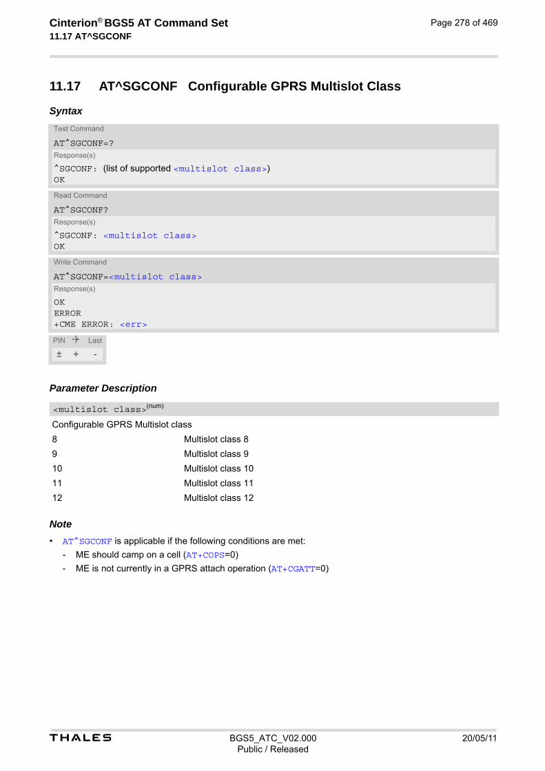
t BGS5_ATC_V02.000 20/05/11Public / Released
Cinterion® BGS5 AT Command Set 11.17 AT^SGCONF
Page 278 of 469
11.17 AT^SGCONF Configurable GPRS Multislot Class
Syntax
Parameter Description
Configurable GPRS Multislot class
8 Multislot class 8
9 Multislot class 9
10 Multislot class 10
11 Multislot class 11
12 Multislot class 12 Note• AT^SGCONF is applicable if the following conditions are met:
- ME should camp on a cell (AT+COPS=0)
- ME is not currently in a GPRS attach operation (AT+CGATT=0)
Test Command
AT^SGCONF=?Response(s)
^SGCONF: (list of supported <multislot class>)OK
Read Command
AT^SGCONF?Response(s)
^SGCONF: <multislot class>OK
Write Command
AT^SGCONF=<multislot class>Response(s)
OKERROR+CME ERROR: <err>
PIN Last
± + -
<multislot class>(num)

Cinterion® BGS5 AT Command Set 12. Short Message Service (SMS) Commands
t BGS5_ATC_V02.000 20/05/11Public / Released
Page 279 of 469
12. Short Message Service (SMS) Commands
The AT Commands described in this chapter allow an external application to use the Short Message Service with the BGS5.
12.1 SMS Parameters
Parameter Description
Format is same for <pdu> in case of SMS, but without 3GPP TS 24.011 [37] SC address field and parameter shall be bounded by double quote characters like a normal string type parameter
String type alphanumeric representation of <da> or <oa> corresponding to the entry found in phonebook. This feature is not supported.
Command Data
3GPP TS 23.040 [34] TP-Command-Data in text mode responses; ME converts each 8-bit octet into two IRA character long hexadecimal numbers, e.g. octet with integer value 42 is represented as two characters "2A", IRA 50 and 65 (decimal).
Command Type
3GPP TS 23.040 [34] TP-Command-Type in integer format
0...255
Destination Address
3GPP TS 23.040 [34] TP- Destination-Address Address-Value field in string format; BCD numbers (or GSM default alphabet characters) are converted into characters; type of address given by <toda>
User Data
In case of SMS: 3GPP TS 23.040 [34] TP-User-Data in text mode responses; format:
• If <dcs> indicates that 3GPP TS 23.038 [33] GSM 7 bit default alphabet is used and <fo> indicates that 3GPP TS 23.040 [34] TP-User-Data-Header-Indication is not set: ME converts GSM alphabet into current TE character set according to rules covered in Annex A.
• If <dcs> indicates that 8-bit or UCS2 data coding scheme is used, or <fo> indicates that 3GPP TS 23.040 [34] TP-User-Data-Header-Indication is set: ME converts each 8-bit octet into hexadecimal numbers con-tain-ing two IRA characters, e.g. octet with integer value 42 is represented as two characters "2A", IRA 50 and 65 (decimal).
In case of CBS: 3GPP TS 23.041 [35] CBM Content of Message in text mode responses; format:
• If <dcs> indicates that 3GPP TS 23.038 [33] GSM 7 bit default alphabet is used: ME converts GSM alphabet into current TE character set according to rules covered in Annex A.
• If <dcs> indicates that 8-bit or UCS2 data coding scheme is used: ME converts each 8-bit octet into hexa-decimal numbers containing two IRA characters.
<ackpdu>(num)
<alpha>(str)(+CSCS)
<cdata>(num)
<ct>(num)
<da>(str)(+CSCS)
<data>(num)(+CSCS)
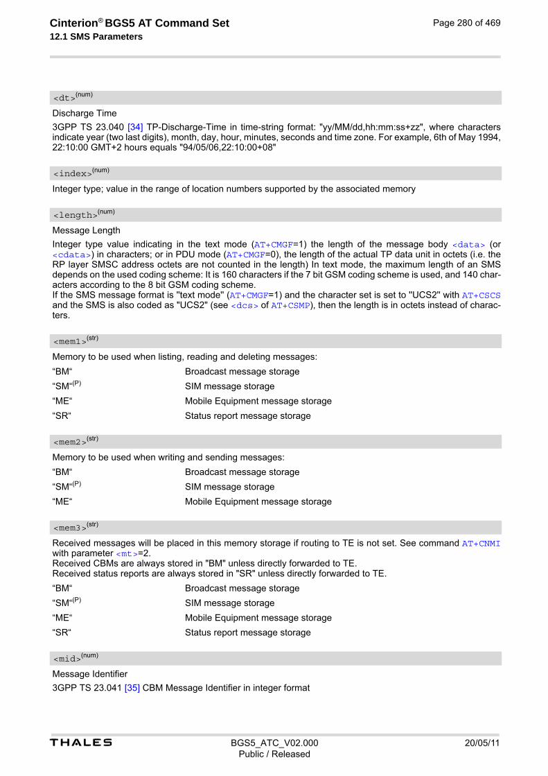
t BGS5_ATC_V02.000 20/05/11Public / Released
Cinterion® BGS5 AT Command Set 12.1 SMS Parameters
Page 280 of 469
Discharge Time
3GPP TS 23.040 [34] TP-Discharge-Time in time-string format: "yy/MM/dd,hh:mm:ss+zz", where characters indicate year (two last digits), month, day, hour, minutes, seconds and time zone. For example, 6th of May 1994, 22:10:00 GMT+2 hours equals "94/05/06,22:10:00+08"
Integer type; value in the range of location numbers supported by the associated memory
Message Length
Integer type value indicating in the text mode (AT+CMGF=1) the length of the message body <data> (or <cdata>) in characters; or in PDU mode (AT+CMGF=0), the length of the actual TP data unit in octets (i.e. the RP layer SMSC address octets are not counted in the length) In text mode, the maximum length of an SMS depends on the used coding scheme: It is 160 characters if the 7 bit GSM coding scheme is used, and 140 char-acters according to the 8 bit GSM coding scheme. If the SMS message format is ''text mode'' (AT+CMGF=1) and the character set is set to ''UCS2'' with AT+CSCS and the SMS is also coded as "UCS2" (see <dcs> of AT+CSMP), then the length is in octets instead of charac-ters.
Memory to be used when listing, reading and deleting messages:
“BM“ Broadcast message storage
“SM“(P) SIM message storage
“ME“ Mobile Equipment message storage
“SR“ Status report message storage
Memory to be used when writing and sending messages:
“BM“ Broadcast message storage
“SM“(P) SIM message storage
“ME“ Mobile Equipment message storage
Received messages will be placed in this memory storage if routing to TE is not set. See command AT+CNMI with parameter <mt>=2. Received CBMs are always stored in "BM" unless directly forwarded to TE. Received status reports are always stored in "SR" unless directly forwarded to TE.
“BM“ Broadcast message storage
“SM“(P) SIM message storage
“ME“ Mobile Equipment message storage
“SR“ Status report message storage
Message Identifier
3GPP TS 23.041 [35] CBM Message Identifier in integer format
<dt>(num)
<index>(num)
<length>(num)
<mem1>(str)
<mem2>(str)
<mem3>(str)
<mid>(num)

t BGS5_ATC_V02.000 20/05/11Public / Released
Cinterion® BGS5 AT Command Set 12.1 SMS Parameters
Page 281 of 469
Message Number
3GPP TS 23.040 [34] TP-Message-Number in integer format
Message Reference
3GPP TS 23.040 [34] TP-Message-Reference in integer format
Originating Address
3GPP TS 23.040 [34] TP-Originating-Address Address-Value field in string format; BCD numbers (or GSM default alphabet characters) are converted into characters; type of address given by <tooa>
Page Parameter
3GPP TS 23.041 [35] CBM Page Parameter bits 4-7 in integer format
Page Parameter
3GPP TS 23.041 [35] CBM Page Parameter bits 0-3 in integer format
In the case of SMS: 3GPP TS 24.011 [37] SC address followed by 3GPP TS 23.040 [34] TPDU in hexadecimal format: ME converts each octet of TP data unit into hexadecimal numbers containing two IRA characters, e.g. octet with integer value 42 is represented as two characters "2A", IRA 50 and 65 (decimal). In the case of CBS: <ra> 3GPP TS 23.040 [34] TP-Recipient-Address Ad-dress-Value field in string format; BCD numbers (or GSM default alphabet characters) are converted into characters; type of address given by <tora>
Recipient Address
3GPP TS 23.040 [34] TP-Recipient-Address Address-Value field in string format; BCD numbers (or GSM default alphabet characters) are converted to characters of the currently selected TE character set (refer to command AT+CSCS.); type of address given by <tora>
Service Center Address
3GPP TS 24.011 [37] RP SC address Address-Value field in string format; BCD numbers (or GSM default alpha-bet characters) are converted to characters of the currently selected TE character set (AT+CSCS); type of address given by <tosca>
Service Centre Time Stamp
3GPP TS 23.040 [34] TP-Service-Centre-Time-Stamp in time-string format (refer <dt>)
Serial Number
3GPP TS 23.041 [35] CBM Serial Number in integer format
<mn>(num)
<mr>(num)
<oa>(str)(+CSCS)
<page>(num)
<pages>(num)
<pdu>(num)
<ra>(str)(+CSCS)
<sca>(str)(+CSCS)
<scts>(num)
<sn>(num)

t BGS5_ATC_V02.000 20/05/11Public / Released
Cinterion® BGS5 AT Command Set 12.1 SMS Parameters
Page 282 of 469
Status
3GPP TS 23.040 [34] TP-Status in integer format
0...255
Message status
3GPP TS 27.005 [42] Interface of SMS and CB. Indicates the status of message in memory.
Type of Destination Address
3GPP TS 24.011 [37] TP-Destination-Address Type-of-Address octet in integer format (when first character of <da> is + (IRA 43) default is 145, otherwise default is 129)
0...255
Type of Originating Address
3GPP TS 24.011 [37] TP-Originating-Address Type-of-Address octet in integer format (default refer <toda>)
Type of Recipient Address
3GPP TS 24.011 [37] TP-Recipient-Address Type-of-Address octet in integer format (default refer <toda>)
Type of Service Center Address
3GPP TS 24.011 [37] RP SC address Type-of-Address octet in integer format (default refer <toda>)
<st>(num)
<stat>(str)
Description text mode (<mode>=1) PDU mode (<mode>=0) Default
Received unread mes-sages
"REC UNREAD" 0 for SMS reading com-mands
Received read messages "REC READ" 1
Stored unsent messages "STO UNSENT" 2 for SMS writing com-mands
Stored sent messages "STO SENT" 3
All messages "ALL" 4
<toda>(num)
<tooa>(num)
<tora>(num)
<tosca>(num)
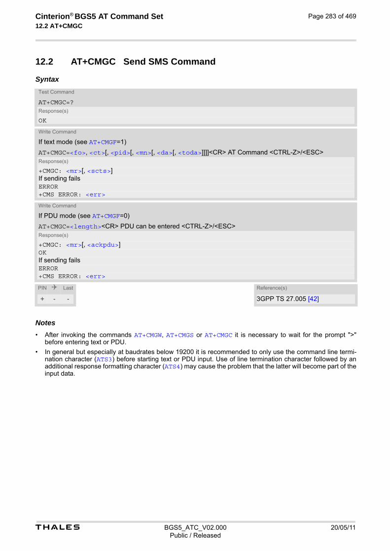
t BGS5_ATC_V02.000 20/05/11Public / Released
Cinterion® BGS5 AT Command Set 12.2 AT+CMGC
Page 283 of 469
12.2 AT+CMGC Send SMS Command
Syntax
Notes• After invoking the commands AT+CMGW, AT+CMGS or AT+CMGC it is necessary to wait for the prompt ">"
before entering text or PDU.
• In general but especially at baudrates below 19200 it is recommended to only use the command line termi-nation character (ATS3) before starting text or PDU input. Use of line termination character followed by an additional response formatting character (ATS4) may cause the problem that the latter will become part of the input data.
Test Command
AT+CMGC=?Response(s)
OK
Write Command
If text mode (see AT+CMGF=1)
AT+CMGC=<fo>, <ct>[, <pid>[, <mn>[, <da>[, <toda>]]]]<CR> AT Command <CTRL-Z>/<ESC>Response(s)
+CMGC: <mr>[, <scts>]If sending failsERROR+CMS ERROR: <err>
Write Command
If PDU mode (see AT+CMGF=0)
AT+CMGC=<length><CR> PDU can be entered <CTRL-Z>/<ESC>Response(s)
+CMGC: <mr>[, <ackpdu>]OKIf sending failsERROR+CMS ERROR: <err>
PIN Last Reference(s)
+ - - 3GPP TS 27.005 [42]

t BGS5_ATC_V02.000 20/05/11Public / Released
Cinterion® BGS5 AT Command Set 12.3 AT+CMGD
Page 284 of 469
12.3 AT+CMGD Delete short message
The AT+CMGD write command deletes a short message from the preferred message storage <mem1> location <index>. If <delflag> is present and not set to 0 then the ME shall ignore <index> and follow the rules for <delflag> shown below. If deleting fails, final result code +CMS ERROR is returned. The AT+CMGD test command returns the valid <index> locations of the preferred <mem1> and the supported <delflag> values.
Syntax
Parameter Description
Integer type; value in the range of location numbers supported by the associated memory. See <index>.
0 (Or omitted) delete the message specified in <index>.
1 Delete all read messages from preferred message storage, leaving unread messages and stored mobile originated messages (whether sent or not) untouched.
2 Delete all read messages from preferred message storage and sent mobile originated messages, leaving unread messages and unsent mobile originated messages untouched.
3 Delete all read messages from preferred message storage, sent and unsent mobile originated messages leaving unread messages untouched.
4 Delete all messages from preferred message storage including unread mes-sages.
Note• If there is no short message stored at the selected index, the response is OK too.
Test Command
AT+CMGD=?Response(s)
+CMGD: (list of supported <index>s), (list of supported <delflag>es)OK
Write Command
AT+CMGD=<index>[, <delflag>]Response(s)
OKERROR+CMS ERROR: <err>
PIN Last Reference(s)
+ + - 3GPP TS 27.005 [42]
<index>(num)
<delflag>(num)

t BGS5_ATC_V02.000 20/05/11Public / Released
Cinterion® BGS5 AT Command Set 12.4 AT+CMGF
Page 285 of 469
12.4 AT+CMGF Select SMS message format
The AT+CMGF command specifies the input and output format of the short messages.
Syntax
Parameter Description
[0](&F)(D) PDU mode (default when implemented)
1 Text mode
Test Command
AT+CMGF=?Response(s)
+CMGF: (list of supported<mode>s)OK
Read Command
AT+CMGF?Response(s)
+CMGF: <mode>OKERROR+CMS ERROR: <err>
Write Command
AT+CMGF=[<mode>]Response(s)
OKERROR+CMS ERROR: <err>
PIN Last Reference(s)
- + - 3GPP TS 27.005 [42]
<mode>(num)(&V)(&W)

t BGS5_ATC_V02.000 20/05/11Public / Released
Cinterion® BGS5 AT Command Set 12.5 AT+CMGL
Page 286 of 469
12.5 AT+CMGL List SMS messages from preferred store
The write command returns messages with status value <stat> from message storage <mem1> to the TE. If the status of the message is 'received unread', the status in the storage changes to 'received read'. The execute command is the same as the write command with the given default for <stat>.
Syntax
Test Command
AT+CMGL=?Response(s)
+CMGL: (list of supported <stat>s)OK
Exec Command
AT+CMGLResponse(s)
+CMGL: (see write command for default of <stat>)OK
Write Command
AT+CMGL=<stat>Response(s)
Output if text mode (AT+CMGF=1) and command successful: For SMS- SUBMITs and/or SMS-DELIVERs +CMGL: <index>, <stat>, <oa>/<da>, [<alpha>], [<scts>][, <tooa>/<toda>, <length>]<CR><LF><data><CR><LF>[... ]OK
For SMS-STATUS-REPORTs +CMGL: <index>, <stat>, <fo>, <mr>, [<ra>], [<tora>], <scts>, <dt>, <st><CR><LF>[... ]OK
For SMS-Commands +CMGL: <index>, <stat>, <fo>, <ct><CR><LF>[... ]OK
Output if PDU mode AT+CMGF=0 and command successful: For SMS-SUBMITs and/or SMS-DELIVERs +CMGL: <index>, <stat>, [<alpha>], <length><CR><LF><pdu><CR><LF>[... ]OK
If error is related to ME functionalityERROR+CMS ERROR: <err>
PIN Last Reference(s)
+ + - 3GPP TS 27.005 [42]
t BGS5_ATC_V02.000 20/05/11Public / Released
Cinterion® BGS5 AT Command Set 12.5 AT+CMGL
Page 287 of 469
Notes• The selected <mem1> can contain different types of SMs (e.g. SMS-DELIVERs, SMS-SUBMITs, SMS-STA-
TUS-REPORTs and SMS-COMMANDs), the response may be a mix of the responses of different SM types. TE application can recognize the response format by examining the third response parameter.
• Users should be aware that when using this AT command quickly after SIM PIN authentication the SIM data may not yet be accessible, resulting in a short delay before the requested AT command response is returned. See Section 21.1, Restricted access to SIM data after SIM PIN authentication for further detail.

t BGS5_ATC_V02.000 20/05/11Public / Released
Cinterion® BGS5 AT Command Set 12.6 AT+CMGR
Page 288 of 469
12.6 AT+CMGR Read SMS messages
The write command returns SMS message with location value <index> from message storage <mem1> to the TE. If status of the message is 'received unread', status in the storage changes to 'received read'. When using Text mode it is recommended to set AT+CSDH=1. In this case the AT+CMGR write command responses will include detailed header information. See AT+CSDH for details.
SyntaxTest Command
AT+CMGR=?Response(s)
OKERROR+CME ERROR: <err>
Write Command
AT+CMGR=<index>Response(s)
Output if text mode (AT+CMGF=1) and command successful: For SMS-DELIVER +CMGR: <stat>, <oa>, [<alpha>], <scts>[, <tooa>, <fo>, <pid>, <dcs>, <sca>, <tosca>, <length>]<CR><LF><data>[... ]OKERROR+CME ERROR: <err>
For SMS-SUBMIT +CMGR: <stat>, <da>, [<alpha>][, <toda>, <fo>, <pid>, <dcs>, [<vp>], <sca>, <tosca>, <length>]<CR><LF><data>[... ]OK
For SMS-STATUS-REPORT +CMGR: <stat>, <fo>, <mr>, [<ra>], [<tora>], <scts>, <dt>, <st><data>[... ]OK
For SMS-Commands +CMGR: <stat>, <fo>, <ct>[, <pid>, [<mn>], [<da>], [<toda>], <length><CR><LF><data>][... ]OK
Output if PDU mode (AT+CMGF=0) and command successful: For SMS-SUBMITs and/or SMS-DELIVERs +CMGR: <stat>, [<alpha>], <length><CR><LF><pdu>[... ]OKERROR+CMS ERROR: <err>+CME ERROR: <err>
t BGS5_ATC_V02.000 20/05/11Public / Released
Cinterion® BGS5 AT Command Set 12.6 AT+CMGR
Page 289 of 469
Notes• Response if AT+CMGR is used to read an empty record index: +CMGR: 0,,0
• Response if AT+CMGR is used to read a non-existent record index: +CMS ERROR: invalid memory index
PIN Last Reference(s)
+ + - 3GPP TS 27.005 [42]

t BGS5_ATC_V02.000 20/05/11Public / Released
Cinterion® BGS5 AT Command Set 12.7 AT+CMGS
Page 290 of 469
12.7 AT+CMGS Send SMS
AT+CMGS write command transmits a short message to network (SMS-SUBMIT). After invoking the write command wait for the prompt ">" and then start to write the message. To send the mes-sage simply enter <CTRL-Z>. To abort sending use <ESC>. Abortion is acknowledged with "OK", though the message will not be sent. The message reference <mr> is returned by the ME on successful message delivery. The value can be used to identify the message in a delivery status report provided as an unsolicited result code.
Syntax
Notes• Note that some providers do not recognize an @ symbol used in a short message. A widely used alternative
is typing "*" as defined in 3GPP TS 23.040 [34].
• All characters entered behind the prompt ">" will be recognized as GSM characters. For example, "Back-space" (ASCII character 8) does not delete a character, but will be inserted into the short message as an addi-tional physical character. As a result, the character you wanted to delete still appears in the text, plus the GSM code equivalent of the Backspace key.
• Message Length in Text Mode The maximum length of a short message depends on the used coding scheme: It is 160 characters if the 7 bit GSM coding scheme is used, and 140 characters according to the 8 bit GSM coding scheme. In case UCS2 character set selected it is highly recommended to set Data Coding Scheme (<dcs> of AT+CSMP) to 16-bit data, otherwise the length of sms user data is restricted to 88 octets. Even better for mes-sages with UCS2 character set is the PDU Mode.
Test Command
AT+CMGS=?Response(s)
OK
Write Command
If text mode (see AT+CMGF=1)
AT+CMGS=<da>[, <toda>]<CR> Text can be entered. <CTRL-Z>/<ESC>Response(s)
+CMGS: <mr>[, <scts>]OKIf sending fails see notes below.ERROR+CMS ERROR: <err>
Write Command
If PDU mode (see AT+CMGF=0)
AT+CMGS=<length><CR> PDU can be entered. <CTRL-Z>/<ESC>Response(s)
+CMGS: <mr>[, <ackpdu>]OKIf sending fails see notes below.ERROR+CMS ERROR: <err>
PIN Last Reference(s)
+ - - 3GPP TS 27.005 [42]
t BGS5_ATC_V02.000 20/05/11Public / Released
Cinterion® BGS5 AT Command Set 12.7 AT+CMGS
Page 291 of 469
• In general but especially at baudrates below 19200 it is recommended to only use the command line termi-nation character (ATS3) before starting text or PDU input. Use of line termination character followed by an additional response formatting character (ATS4) may cause the problem that the latter will become part of the input data.

t BGS5_ATC_V02.000 20/05/11Public / Released
Cinterion® BGS5 AT Command Set 12.8 AT+CMGW
Page 292 of 469
12.8 AT+CMGW Write Short Messages to Memory
AT+CMGW execute and write commands transmit a short message (either SMS-DELIVER or SMS-SUBMIT) from TE to memory storage <mem2>. Memory location <index> of the stored message is returned. Message status will be set to 'stored unsent' unless otherwise given in parameter <stat>. After invoking the execute or write command wait for the prompt ">" and then start to write the message. To save the message simply enter <CTRL-Z>. To abort writing use <ESC>. Abortion is acknowledged with "OK", though the message will not be saved. Message Length in Text Mode: The maximum length of a short message depends on the used coding scheme configured with <dcs> of AT+CSMP: 7 bit GSM coding scheme: 160 characters 8 bit GSM coding scheme: 140 characters 16 bit GSM coding scheme: 70 characters. The length of 8-bit data coded short messages has to be greater than 0.
SyntaxTest Command
AT+CMGW=?Response(s)
OKERROR+CME ERROR: <err>
Exec Command
If text mode (see AT+CMGF=1):
AT+CMGWResponse(s)
<CR> Text can be entered. <CTRL-Z>/<ESC> +CMGW: <index>OKIf writing failsERROR+CMS ERROR: <err>+CME ERROR: <err>
Write Command
If text mode (see AT+CMGF=1):
AT+CMGW=<oa>/<da>[, [<tooa>/<toda>][, <stat>]]<CR> Text can be entered. <CTRL-Z>/<ESC>Response(s)
+CMGW: <index>OKIf writing fails ERROR+CMS ERROR: <err>+CME ERROR: <err>
Write Command
If PDU mode (see AT+CMGF=0):
AT+CMGW=<length>[, <stat>]<CR> PDU can be entered. <CTRL-Z>/<ESC>Response(s)
+CMGW: <index>OKIf writing fails

t BGS5_ATC_V02.000 20/05/11Public / Released
Cinterion® BGS5 AT Command Set 12.8 AT+CMGW
Page 293 of 469
Notes• Note that some providers do not recognize an @ symbol used in a short message. A widely used alternative
is typing "*" as defined in 3GPP TS 23.040 [34].
• In general but especially at baudrates below 19200 it is recommended to only use the command line termi-nation character (ATS3) before starting text or PDU input. Use of line termination character followed by an additional response formatting character (ATS4) may cause the problem that the latter will become part of the input data.
• SMS-COMMANDs and SMS-STATUS-REPORTs cannot be stored in text mode.
• All characters entered behind the ">" prompt will be recognized as GSM characters. For example, "Back-space" (ASCII character 8) does not delete a character, but will be inserted into the short message as an addi-tional physical character. As a result, the character you wanted to delete still appears in the text, plus the GSM code equivalent of the Backspace key.
ERROR+CMS ERROR: <err>+CME ERROR: <err>
PIN Last Reference(s)
+ + - 3GPP TS 27.005 [42], 3GPP TS 23.038 [33]
Write Command (Continued)
If PDU mode (see AT+CMGF=0):
AT+CMGW=<length>[, <stat>]<CR> PDU can be entered. <CTRL-Z>/<ESC>Response(s)

t BGS5_ATC_V02.000 20/05/11Public / Released
Cinterion® BGS5 AT Command Set 12.9 AT+CMMS
Page 294 of 469
12.9 AT+CMMS More Messages to Send
AT+CMMS controls the continuity of the SMS relay protocol link. If the feature is enabled (and supported by the currently used network) multiple messages can be sent faster as the link is kept open.
Syntax
Parameter Description
[0](P) Feature disabled.
1 Keep link open until the time between the response of the latest message send command (AT+CMGS, AT+CMSS, etc.) and the next send command exceeds 1-5 seconds. Afterwards ME will close the link and automatically switches <mode> back to 0.
2 Keep link open until the time between the response of the latest messages send command (AT+CMGS, AT+CMSS, etc.) and the next send command exceeds 1-5 seconds. Afterwards ME will close the link, but will not reset <mode> to 0.
Test Command
AT+CMMS=?Response(s)
+CMMS: (list of supported) <mode>s
Read Command
AT+CMMS?Response(s)
+CMMS: <mode>OK
Write Command
AT+CMMS=<mode>Response(s)
OKERROR+CMS ERROR: <err>
PIN Last Reference(s)
+ + - 3GPP TS 27.005 [42]
<mode>(num)
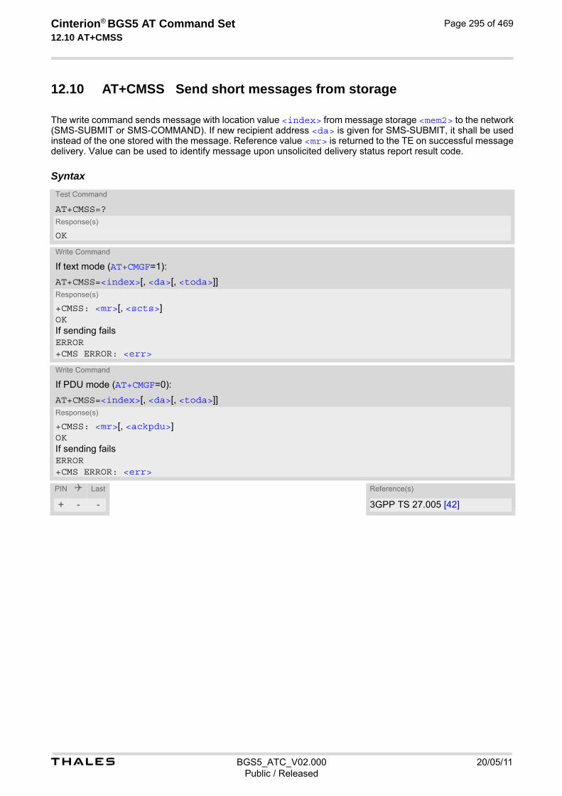
t BGS5_ATC_V02.000 20/05/11Public / Released
Cinterion® BGS5 AT Command Set 12.10 AT+CMSS
Page 295 of 469
12.10 AT+CMSS Send short messages from storage
The write command sends message with location value <index> from message storage <mem2> to the network (SMS-SUBMIT or SMS-COMMAND). If new recipient address <da> is given for SMS-SUBMIT, it shall be used instead of the one stored with the message. Reference value <mr> is returned to the TE on successful message delivery. Value can be used to identify message upon unsolicited delivery status report result code.
SyntaxTest Command
AT+CMSS=?Response(s)
OK
Write Command
If text mode (AT+CMGF=1):
AT+CMSS=<index>[, <da>[, <toda>]]Response(s)
+CMSS: <mr>[, <scts>]OKIf sending failsERROR+CMS ERROR: <err>
Write Command
If PDU mode (AT+CMGF=0):
AT+CMSS=<index>[, <da>[, <toda>]]Response(s)
+CMSS: <mr>[, <ackpdu>]OKIf sending failsERROR+CMS ERROR: <err>
PIN Last Reference(s)
+ - - 3GPP TS 27.005 [42]
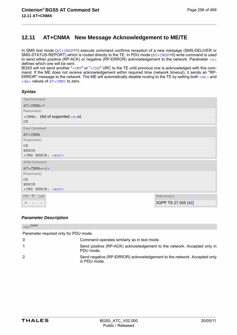
t BGS5_ATC_V02.000 20/05/11Public / Released
Cinterion® BGS5 AT Command Set 12.11 AT+CNMA
Page 296 of 469
12.11 AT+CNMA New Message Acknowledgement to ME/TE
In SMS text mode (AT+CMGF=1) execute command confirms reception of a new message (SMS-DELIVER or SMS-STATUS-REPORT) which is routed directly to the TE. In PDU mode (AT+CMGF=0) write command is used to send either positive (RP-ACK) or negative (RP-ERROR) acknowledgement to the network. Parameter <n> defines which one will be sent. BGS5 will not send another "+CMT" or "+CDS" URC to the TE until previous one is acknowledged with this com-mand. If the ME does not receive acknowledgement within required time (network timeout), it sends an "RP-ERROR" message to the network. The ME will automatically disable routing to the TE by setting both <mt> and <ds> values of AT+CNMI to zero.
Syntax
Parameter Description
Parameter required only for PDU mode.
0 Command operates similarly as in text mode.
1 Send positive (RP-ACK) acknowledgement to the network. Accepted only in PDU mode.
2 Send negative (RP-ERROR) acknowledgement to the network. Accepted only in PDU mode.
Test Command
AT+CNMA=?Response(s)
+CNMA: (list of supported <n>s)OK
Exec Command
AT+CNMAResponse(s)
OKERROR+CMS ERROR: <err>
Write Command
AT+CNMA=<n>Response(s)
OKERROR+CMS ERROR: <err>
PIN Last Reference(s)
+ - - 3GPP TS 27.005 [42]
<n>(num)

t BGS5_ATC_V02.000 20/05/11Public / Released
Cinterion® BGS5 AT Command Set 12.11 AT+CNMA
Page 297 of 469
Notes• Execute and write command shall only be used when AT+CSMS parameter <service> equals 1 (= phase
2+) and an appropriate URC has been issued by the module, i.e.: "+CMT" for <mt>=2 incoming message classes 0,1,3 and none; "+CMT" for <mt>=3 incoming message classes 0 and 3; "+CDS" for <ds>=1.
• Execute command can be used no matter whether text mode or PDU mode is activated. Write command is designed for the PDU mode only.

t BGS5_ATC_V02.000 20/05/11Public / Released
Cinterion® BGS5 AT Command Set 12.12 AT+CNMI
Page 298 of 469
12.12 AT+CNMI SMS Event Reporting Configuration
AT+CNMI selects the procedure how the receipt of a new SMS from the network is indicated to the TE when TE is active. Please also consider general rules for URC signaling explained in Section 1.8, Unsolicited Result Code Presentation and in Section 2.12, Extended Configuration Settings. Changing AT+CNMI parameters on one of the ME's interfaces will automatically restore AT+CNMI factory settings on all other interfaces. This ensures that incoming short messages are always indicated on the interface from which the AT+CNMI command was most recently issued. The rules <mt>=2 and <mt>=3 for storing received messages are possible only if phase 2+ compatibility is acti-vated with AT+CSMS=1. The parameter <ds>=1 is only available in phase 2+.
Syntax
Unsolicited Result Codes
URC 1
<mt>=1:
+CMTI: <mem3>, <index>
Indicates that new message has been received
URC 2
<mt>=2 (PDU mode enabled):
+CMT: [<alpha>], <length><CR><LF><pdu>
Indicates that new message has been received
URC 3
<mt>=2 (text mode enabled):
+CMT: <oa>, [<alpha>], <scts>[, <tooa>, <fo>, <pid>, <dcs>, <sca>, <tosca>, <length>]<CR><LF><data>
Indicates that new message has been received
Test Command
AT+CNMI=?Response(s)
+CNMI: (list of supported<mode>s), (list of supported <mt>s), (list of supported <bm>s), (list of supported <ds>s), (list of supported <bfr>s)OK
Read Command
AT+CNMI?Response(s)
+CNMI: <mode>, <mt>, <bm>, <ds>, <bfr>OK
Write Command
AT+CNMI=<mode>[, <mt>[, <bm>[, <ds>[, <bfr>]]]]Response(s)
OKERROR+CMS ERROR: <err>
PIN Last Reference(s)
+ + - 3GPP TS 27.005 [42]

t BGS5_ATC_V02.000 20/05/11Public / Released
Cinterion® BGS5 AT Command Set 12.12 AT+CNMI
Page 299 of 469
URC 4
<bm>=2 (PDU mode enabled):
+CBM: <length><CR><LF><pdu>
Indicates that new cell broadcast message has been received
URC 5
<bm>=2 (text mode enabled):
+CBM: <sn>, <mid>, <dcs>, <page>, <pages><CR><LF><data>
Indicates that new cell broadcast message has been received
URC 6
<bm>=1 or 3:
+CBMI: <mem3>, <index>
Indicates memory location of newly received cell broadcast message
URC 7
<ds>=1 (PDU mode enabled):
+CDS: <length><CR><LF><pdu>
Indicates that new SMS status report has been received
URC 8
<ds>=1 (text mode enabled):
+CDS: <fo>, <mr>[, <ra>][, <tora>], <scts>, <dt>, <st>
Indicates that new SMS status report has been received
URC 9
<ds>=2:
+CDSI: <mem3>, <index>
Indicates that new SMS status report has been received Parameter Description
[0] SMS related URCs are always buffered in the ME. If the buffer is full, the oldest indications are discarded and replaced with newly received indications.
1(&F)(P) SMS related URCs are forwarded directly to the TE. However, if this is not pos-sible because ME-TE link is reserved, e.g. during a data call, these URCs are discarded.
2 SMS related URCs are forwarded directly to the TE. However, if this is not pos-sible because ME-TE link is reserved these URCs are buffered and flushed to the TE afterwards.
Rules for storing received short messages depend on the relevant data coding method (refer to 3GPP TS 23.038 [33]), preferred memory storage (AT+CPMS) setting and this value.
[0](&F)(P) No SMS-DELIVER indications are routed to the TE.
1 Class 0 SMS-DELIVERs are routed directly to the TE via URC. For all other messages the following applies: If SMS-DELIVER is stored in UE, indication of the memory location is routed to the TE via URC.
<mode>(num)(&V)(&W)
<mt>(num)(&V)(&W)
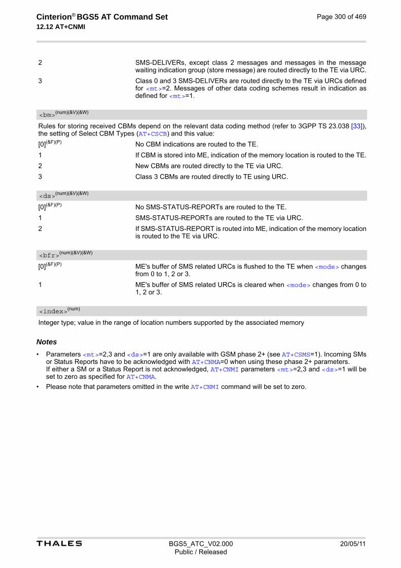
t BGS5_ATC_V02.000 20/05/11Public / Released
Cinterion® BGS5 AT Command Set 12.12 AT+CNMI
Page 300 of 469
2 SMS-DELIVERs, except class 2 messages and messages in the message waiting indication group (store message) are routed directly to the TE via URC.
3 Class 0 and 3 SMS-DELIVERs are routed directly to the TE via URCs defined for <mt>=2. Messages of other data coding schemes result in indication as defined for <mt>=1.
Rules for storing received CBMs depend on the relevant data coding method (refer to 3GPP TS 23.038 [33]), the setting of Select CBM Types (AT+CSCB) and this value:
[0](&F)(P) No CBM indications are routed to the TE.
1 If CBM is stored into ME, indication of the memory location is routed to the TE.
2 New CBMs are routed directly to the TE via URC.
3 Class 3 CBMs are routed directly to TE using URC.
[0](&F)(P) No SMS-STATUS-REPORTs are routed to the TE.
1 SMS-STATUS-REPORTs are routed to the TE via URC.
2 If SMS-STATUS-REPORT is routed into ME, indication of the memory location is routed to the TE via URC.
[0](&F)(P) ME's buffer of SMS related URCs is flushed to the TE when <mode> changes from 0 to 1, 2 or 3.
1 ME's buffer of SMS related URCs is cleared when <mode> changes from 0 to 1, 2 or 3.
Integer type; value in the range of location numbers supported by the associated memory Notes• Parameters <mt>=2,3 and <ds>=1 are only available with GSM phase 2+ (see AT+CSMS=1). Incoming SMs
or Status Reports have to be acknowledged with AT+CNMA=0 when using these phase 2+ parameters. If either a SM or a Status Report is not acknowledged, AT+CNMI parameters <mt>=2,3 and <ds>=1 will be set to zero as specified for AT+CNMA.
• Please note that parameters omitted in the write AT+CNMI command will be set to zero.
<bm>(num)(&V)(&W)
<ds>(num)(&V)(&W)
<bfr>(num)(&V)(&W)
<index>(num)

t BGS5_ATC_V02.000 20/05/11Public / Released
Cinterion® BGS5 AT Command Set 12.13 AT+CPMS
Page 301 of 469
12.13 AT+CPMS Preferred SMS message storage
The AT+CPMS write command selects memory storages <mem1>,<mem2>, <mem3> to be used for reading, writ-ing, etc. The AT+CPMS test command lists the supported memory storages. The AT+CPMS read command indicates the currently selected memory storages incl. the numbers of used and total entries.
Syntax
Parameter Description
Number of messages currently in <mem1>
Number of messages currently in <mem2>
Number of messages currently in <mem3>
Number of messages storable in <mem1>
Number of messages storable in <mem2>
Test Command
AT+CPMS=?Response(s)
+CPMS: (list of supported <mem1>s), (list of supported <mem2>s), (list of supported <mem3>s)OK
Read Command
AT+CPMS?Response(s)
+CPMS: <mem1>, <used1>, <total1>, <mem2>, <used2>, <total2>, <mem3>, <used3>, <total3>OKERROR+CMS ERROR: <err>
Write Command
AT+CPMS=<mem1>[, <mem2>[, <mem3>]]Response(s)
+CPMS: <used1>, <total1>, <used2>, <total2>, <used3>, <total3>OKERROR+CMS ERROR: <err>
PIN Last Reference(s)
+ + - 3GPP TS 27.005 [42]
<used1>(num)
<used2>(num)
<used3>(num)
<total1>(num)
<total2>(num)

t BGS5_ATC_V02.000 20/05/11Public / Released
Cinterion® BGS5 AT Command Set 12.13 AT+CPMS
Page 302 of 469
Number of messages storable in <mem3> Note• The Mobile Equipment storage "ME" offers space for 4 short messages, see <mem1>.
<total3>(num)
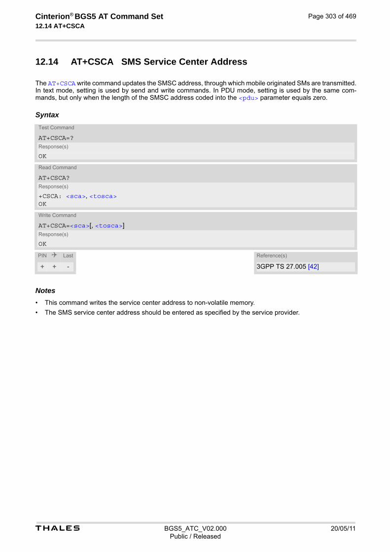
t BGS5_ATC_V02.000 20/05/11Public / Released
Cinterion® BGS5 AT Command Set 12.14 AT+CSCA
Page 303 of 469
12.14 AT+CSCA SMS Service Center Address
The AT+CSCA write command updates the SMSC address, through which mobile originated SMs are transmitted. In text mode, setting is used by send and write commands. In PDU mode, setting is used by the same com-mands, but only when the length of the SMSC address coded into the <pdu> parameter equals zero.
Syntax
Notes• This command writes the service center address to non-volatile memory.
• The SMS service center address should be entered as specified by the service provider.
Test Command
AT+CSCA=?Response(s)
OK
Read Command
AT+CSCA?Response(s)
+CSCA: <sca>, <tosca>OK
Write Command
AT+CSCA=<sca>[, <tosca>]Response(s)
OK
PIN Last Reference(s)
+ + - 3GPP TS 27.005 [42]

t BGS5_ATC_V02.000 20/05/11Public / Released
Cinterion® BGS5 AT Command Set 12.15 AT+CSCB
Page 304 of 469
12.15 AT+CSCB Select Cell Broadcast Message Indication
The test command returns the supported modes as a compound value. The write command selects which types of CBMs are to be received by the ME.
Syntax
Parameter Description
Message mode
0(P) Accept messages that are defined in <mids> and <dcss>
1 Forbid messages that are defined in <mids> and <dcss>
Cell Broadcast Message ID specification
"0"..."65534" Range of CBM identifiers
[““](P) Default value of this parameter is an empty string to indicate that no CBM iden-tifiers are specified.
All different possible combinations of CBM IDs (e.g. "0,1,5,320-478,922,2000-3000"). In certain configurations, e.g. if using SIMs that contain data in Elementary File EF-CBMI (Cell Broadcast Mes-sage Identifier) less than six combinations may be available. To access a SIM's Elementary File data refer to command AT+CRSM. A given <mids> replaces any former value and is used for consecutive requests.
CBM data coding scheme specification
[““](P) Default value of this parameter is empty string
All different possible combinations of CBM data coding schemes (e.g. "0-3,5"). Using default empty string leads to get all CBMs independent of their dcss. A given <dcss> replaces any former value and is used for consecutive requests.
Test Command
AT+CSCB=?Response(s)
+CSCB: (list of supported <mode>s)OK
Read Command
AT+CSCB?Response(s)
+CSCB: <mode>, <mids>, <dcss>OK
Write Command
AT+CSCB=<mode>[, <mids>[, <dcss>]]Response(s)
OK
PIN Last Reference(s)
+ + - 3GPP TS 27.005 [42]
<mode>(num)
<mids>(str)
<dcss>(str)
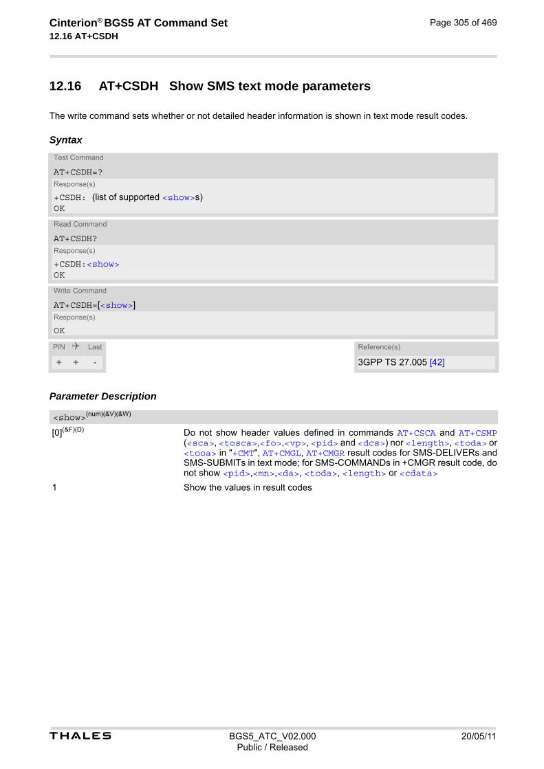
t BGS5_ATC_V02.000 20/05/11Public / Released
Cinterion® BGS5 AT Command Set 12.16 AT+CSDH
Page 305 of 469
12.16 AT+CSDH Show SMS text mode parameters
The write command sets whether or not detailed header information is shown in text mode result codes.
Syntax
Parameter Description
[0](&F)(D) Do not show header values defined in commands AT+CSCA and AT+CSMP (<sca>, <tosca>,<fo>,<vp>, <pid> and <dcs>) nor <length>, <toda> or <tooa> in "+CMT", AT+CMGL, AT+CMGR result codes for SMS-DELIVERs and SMS-SUBMITs in text mode; for SMS-COMMANDs in +CMGR result code, do not show <pid>,<mn>,<da>, <toda>, <length> or <cdata>
1 Show the values in result codes
Test Command
AT+CSDH=?Response(s)
+CSDH: (list of supported <show>s)OK
Read Command
AT+CSDH?Response(s)
+CSDH:<show>OK
Write Command
AT+CSDH=[<show>]Response(s)
OK
PIN Last Reference(s)
+ + - 3GPP TS 27.005 [42]
<show>(num)(&V)(&W)

t BGS5_ATC_V02.000 20/05/11Public / Released
Cinterion® BGS5 AT Command Set 12.17 AT+CSMP
Page 306 of 469
12.17 AT+CSMP Set SMS Text Mode Parameters
AT+CSMP controls additional parameters needed when an SMS is sent to the network or placed in a storage if text format message mode is selected. It is possible to set the validity period starting from the time when the short message is received by the SMSC (<vp> is in the range 0... 255) or define an absolute time for validity period termination (<vp> is a string). The format of <vp> is given by <fo>. The enhanced validity period format is given as hexadecimal coded string (e.g. <pdu>) with quotes.
Syntax
Parameter Description
First Octet
Depending on the command or result code: First octet of 3GPP TS 23.040 [34] SMS-DELIVER, SMS-SUBMIT, SMS-STATUS-REPORT, or SMS-COMMAND in integer format.
0...17(P)...255
Validity Period
Depending on SMS-SUBMIT <fo> setting: 3GPP TS 23.040 [34] TP-Validity-Period either in integer format or in time-string format (refer <dt>).
0...167(D)...255
Protocol Identifier
3GPP TS 23.040 [34] TP-Protocol-Identifier in integer format.
0(P)...255
Test Command
AT+CSMP=?Response(s)
OK
Read Command
AT+CSMP?Response(s)
+CSMP:<fo>, <vp>/ <scts>, <pid>, <dcs>OK
Write Command
AT+CSMP=<fo>, <vp>/<scts>[, <pid>[, <dcs>]]Response(s)
OKERROR+CMS ERROR: <err>
PIN Last Reference(s)
+ + - 3GPP TS 27.005 [42]
<fo>(num)
<vp>(num)(NV)
<pid>(num)

t BGS5_ATC_V02.000 20/05/11Public / Released
Cinterion® BGS5 AT Command Set 12.17 AT+CSMP
Page 307 of 469
Data Coding Scheme
3GPP TS 23.038 [33] SMS Data Coding Scheme, or Cell Broadcast Data Coding Scheme in integer format.
0(P)...247 Note• When storing a SMS DELIVER from the TE to the preferred memory storage in text mode (using the AT+CMGW
write command), <vp> field can be used for <scts>.
<dcs>(num)
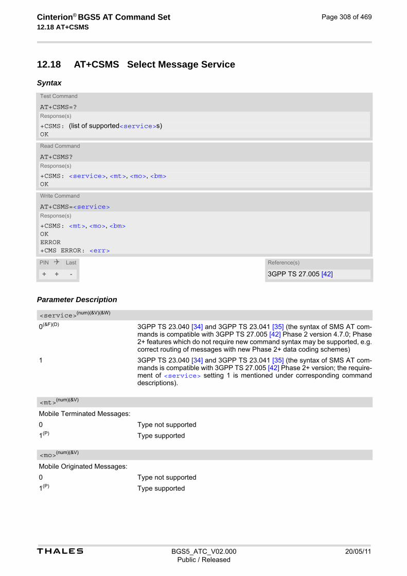
t BGS5_ATC_V02.000 20/05/11Public / Released
Cinterion® BGS5 AT Command Set 12.18 AT+CSMS
Page 308 of 469
12.18 AT+CSMS Select Message Service
Syntax
Parameter Description
0(&F)(D) 3GPP TS 23.040 [34] and 3GPP TS 23.041 [35] (the syntax of SMS AT com-mands is compatible with 3GPP TS 27.005 [42] Phase 2 version 4.7.0; Phase 2+ features which do not require new command syntax may be supported, e.g. correct routing of messages with new Phase 2+ data coding schemes)
1 3GPP TS 23.040 [34] and 3GPP TS 23.041 [35] (the syntax of SMS AT com-mands is compatible with 3GPP TS 27.005 [42] Phase 2+ version; the require-ment of <service> setting 1 is mentioned under corresponding command descriptions).
Mobile Terminated Messages:
0 Type not supported
1(P) Type supported
Mobile Originated Messages:
0 Type not supported
1(P) Type supported
Test Command
AT+CSMS=?Response(s)
+CSMS: (list of supported<service>s)OK
Read Command
AT+CSMS?Response(s)
+CSMS: <service>, <mt>, <mo>, <bm>OK
Write Command
AT+CSMS=<service>Response(s)
+CSMS: <mt>, <mo>, <bm>OKERROR+CMS ERROR: <err>
PIN Last Reference(s)
+ + - 3GPP TS 27.005 [42]
<service>(num)(&V)(&W)
<mt>(num)(&V)
<mo>(num)(&V)

t BGS5_ATC_V02.000 20/05/11Public / Released
Cinterion® BGS5 AT Command Set 12.18 AT+CSMS
Page 309 of 469
Broadcast Type Messages:
0 Type not supported
1(P) Type supported Notes• If CSMS mode is switched from Phase 2+ to Phase 2 and one or more AT+CNMI Parameter are Phase 2+
specific a "+CMS ERROR: unknown error" will appear. It is recommended to switch the AT+CNMI Parameters to Phase 2 specific values before entering Phase 2.
• Phase 2+ (<service>=1) must be set before the following features can be used: - Configuring procedures for indicating received short messages with the AT+CNMI parameters <mt>=2 or <mt>=3 and <ds>=1. - Acknowledging incoming short messages with AT+CNMA. - Receiving Status Reports and acknowledging them with AT+CNMA.
<bm>(num)(&V)
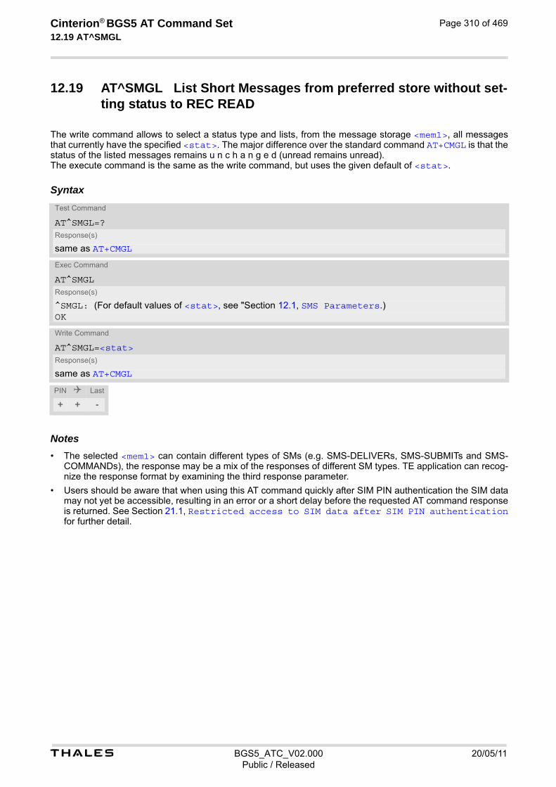
t BGS5_ATC_V02.000 20/05/11Public / Released
Cinterion® BGS5 AT Command Set 12.19 AT^SMGL
Page 310 of 469
12.19 AT^SMGL List Short Messages from preferred store without set-ting status to REC READ
The write command allows to select a status type and lists, from the message storage <mem1>, all messages that currently have the specified <stat>. The major difference over the standard command AT+CMGL is that the status of the listed messages remains u n c h a n g e d (unread remains unread). The execute command is the same as the write command, but uses the given default of <stat>.
Syntax
Notes• The selected <mem1> can contain different types of SMs (e.g. SMS-DELIVERs, SMS-SUBMITs and SMS-
COMMANDs), the response may be a mix of the responses of different SM types. TE application can recog-nize the response format by examining the third response parameter.
• Users should be aware that when using this AT command quickly after SIM PIN authentication the SIM data may not yet be accessible, resulting in an error or a short delay before the requested AT command response is returned. See Section 21.1, Restricted access to SIM data after SIM PIN authentication for further detail.
Test Command
AT^SMGL=?Response(s)
same as AT+CMGL
Exec Command
AT^SMGLResponse(s)
^SMGL: (For default values of <stat>, see "Section 12.1, SMS Parameters.)OK
Write Command
AT^SMGL=<stat>Response(s)
same as AT+CMGL
PIN Last
+ + -
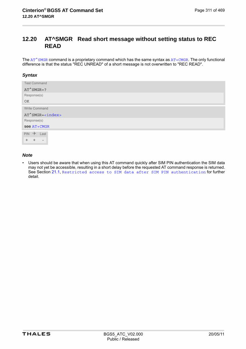
t BGS5_ATC_V02.000 20/05/11Public / Released
Cinterion® BGS5 AT Command Set 12.20 AT^SMGR
Page 311 of 469
12.20 AT^SMGR Read short message without setting status to REC READ
The AT^SMGR command is a proprietary command which has the same syntax as AT+CMGR. The only functional difference is that the status "REC UNREAD" of a short message is not overwritten to "REC READ".
Syntax
Note• Users should be aware that when using this AT command quickly after SIM PIN authentication the SIM data
may not yet be accessible, resulting in a short delay before the requested AT command response is returned. See Section 21.1, Restricted access to SIM data after SIM PIN authentication for further detail.
Test Command
AT^SMGR=?Response(s)
OK
Write Command
AT^SMGR=<index>Response(s)
see AT+CMGR
PIN Last
+ + -

Cinterion® BGS5 AT Command Set 13. SIM related Commands
t BGS5_ATC_V02.000 20/05/11Public / Released
Page 312 of 469
13. SIM related Commands
AT commands described in this chapter are related to the Subscriber Identity Module (SIM) connected to the BGS5.
13.1 AT+CCID SIM Card Identification Number
AT+CCID serves to query the SIM card identification number. This information is retrieved from SIM Elementary File EFICCID. For details refer to 3GPP TS 11.11 [16], 3GPP TS 31.101 [17], 3GPP TS 31.102 [18].
Syntax
Parameter Description
ICCID (Integrated Circuit Card ID) of the SIM card
Test Command
AT+CCID=?Response(s)
OK
Read Command
AT+CCID?Response(s)
+CCID: <ICCID>OKERROR+CME ERROR: <err>
Exec Command
AT+CCIDResponse(s)
+CCID: <ICCID>OKERROR+CME ERROR: <err>
PIN Last
- + -
<ICCID>(str)

t BGS5_ATC_V02.000 20/05/11Public / Released
Cinterion® BGS5 AT Command Set 13.2 AT+CRSM
Page 313 of 469
13.2 AT+CRSM Restricted SIM Access
AT+CRSM offers easy access of the Elementary Files on the SIM. Access to the SIM database is restricted to the commands which are listed at <command>. All parameters of AT+CRSM are used as specified by 3GPP TS 11.11 [16], 3GPP TS 31.101 [17], 3GPP TS 31.102 [18]. BGS5 handles internally all required SIM interface locking and file selection routines. As response to the command, the BGS5 sends the actual SIM information parameters and response data. Error result code "+CME ERROR" may be returned if the command cannot be passed to the SIM, e.g. if the SIM is not inserted. However, failure in the execution of the command in the SIM is reported in <sw1> and <sw2> param-eters.
Syntax
Parameter Description
SIM command number.
176 READ BINARY
178 READ RECORD
192 GET RESPONSE
214 UPDATE BINARY
220 UPDATE RECORD
242 STATUS
Identifier for an elementary data file on SIM, if used by <command>. Mandatory for every command except STA-TUS.
Parameter to be passed on by the BGS5 to the SIM.
0...255
Test Command
AT+CRSM=?Response(s)
OK
Write Command
AT+CRSM=<command>[, <fileID>[, <P1>, <P2>, <P3>[, <data>][, <pathId>]]]Response(s)
+CRSM: <sw1>,<sw2>[,<response>] OK ERROR +CME ERROR: <err>
PIN Last Reference(s)
- + - 3GPP TS 27.007 [43], 3GPP TS 11.11 [16], 3GPP TS 31.101 [17], 3GPP TS 31.102 [18]
<command>(num)
<fileID>(num)
<P1>(num)
t BGS5_ATC_V02.000 20/05/11Public / Released
Cinterion® BGS5 AT Command Set 13.2 AT+CRSM
Page 314 of 469
Parameter to be passed on by the BGS5 to the SIM.
0...255
Parameter to be passed on by the BGS5 to the SIM.
0...255
Information which shall be written to the SIM (hexadecimal character format).
Contains the directory path of an elementary file on the UICC in hexadecimal format (e.g. "7F105F50").
Status information from the SIM about the execution of the actual command. It is returned in both cases, on suc-cessful or failed execution of the command.
0...255
Status information from the SIM about the execution of the actual command. It is returned in both cases, on suc-cessful or failed execution of the command.
0...255
Response data in case of a successful completion of the previously issued command. "STATUS" and "GET RESPONSE" commands return data, which gives information about the currently selected elementary data field. This information includes the type of file and its size. After "READ BINARY" or "READ RECORD" commands the requested data will be returned. <response> is empty after "UPDATE BINARY" or "UPDATE RECORD" commands.
<P2>(num)
<P3>(num)
<data>(str)
<pathId>(str)
<sw1>(num)
<sw2>(num)
<response>(str)

t BGS5_ATC_V02.000 20/05/11Public / Released
Cinterion® BGS5 AT Command Set 13.3 AT+CSIM
Page 315 of 469
13.3 AT+CSIM Generic SIM Access
AT+CSIM allows direct control of the SIM. Compared to Restricted SIM Access command AT+CRSM, the definition of AT+CSIM allows the ME to take more control over the SIM interface. For parameter and SIM result coding please refer to 3GPP TS 11.11 [16], 3GPP TS 31.101 [17], 3GPP TS 31.102 [18]. However, only the following SIM commands are fully supported by AT+CSIM: SELECT, STATUS, READ BINARY, UPDATE BINARY, READ RECORD, UPDATE RECORD, SEEK, INCREASE and GET RESPONSE. Other SIM commands will work in conjunction with the SIM but the correct interaction of the SIM with the BGS5 is not guaranteed.
Syntax
Parameter Description
Number of characters of <command> or <response> string.
Command passed on by the ME to the SIM.
Response data of the command returned by the SIM.
Example The following examples show SELECT and GET RESPONSE commands.
Test Command
AT+CSIM=?Response(s)
OK
Write Command
AT+CSIM=<length>, <command>Response(s)
+CSIM: <length>,<response>OK ERROR +CME ERROR: <err>
PIN Last Reference(s)
- + - 3GPP TS 27.007 [43], 3GPP TS 11.11 [16], 3GPP TS 31.101 [17], 3GPP TS 31.102 [18]
<length>(num)
<command>(str)
<response>(str)
AT+CSIM=14,"A0A40000027F10" SELECT DF-Telecom.+CSIM: 4,"9F19" Command successful. Indicates that x19 bytes
response data are available and can be requested by using GET RESPONSE.
OKAT+CSIM=14,"A0A40000026F3A" SELECT EF-ADN (Abbreviated dialing numbers).
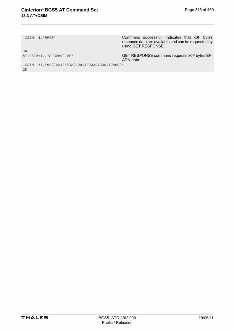
t BGS5_ATC_V02.000 20/05/11Public / Released
Cinterion® BGS5 AT Command Set 13.3 AT+CSIM
Page 316 of 469
+CSIM: 4,"9F0F" Command successful. Indicates that x0F bytes response data are available and can be requested by using GET RESPONSE.
OKAT+CSIM=10,"A0C000000F" GET RESPONSE command requests x0F bytes EF-
ADN data.+CSIM: 34,"000002306F3A040011F0220102011C9000"OK
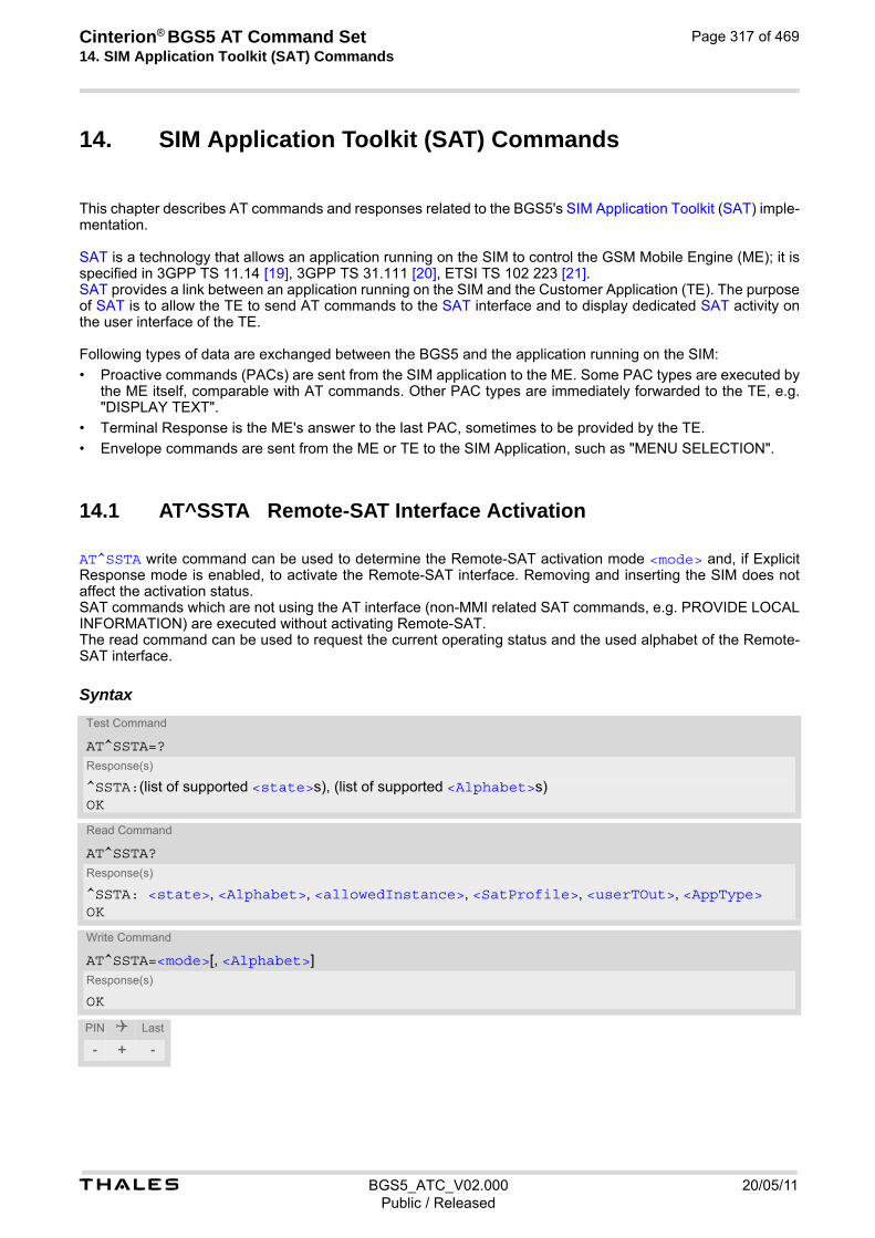
Cinterion® BGS5 AT Command Set 14. SIM Application Toolkit (SAT) Commands
t BGS5_ATC_V02.000 20/05/11Public / Released
Page 317 of 469
14. SIM Application Toolkit (SAT) Commands
This chapter describes AT commands and responses related to the BGS5's SIM Application Toolkit (SAT) imple-mentation. SAT is a technology that allows an application running on the SIM to control the GSM Mobile Engine (ME); it is specified in 3GPP TS 11.14 [19], 3GPP TS 31.111 [20], ETSI TS 102 223 [21]. SAT provides a link between an application running on the SIM and the Customer Application (TE). The purpose of SAT is to allow the TE to send AT commands to the SAT interface and to display dedicated SAT activity on the user interface of the TE. Following types of data are exchanged between the BGS5 and the application running on the SIM:
• Proactive commands (PACs) are sent from the SIM application to the ME. Some PAC types are executed by the ME itself, comparable with AT commands. Other PAC types are immediately forwarded to the TE, e.g. "DISPLAY TEXT".
• Terminal Response is the ME's answer to the last PAC, sometimes to be provided by the TE.
• Envelope commands are sent from the ME or TE to the SIM Application, such as "MENU SELECTION".
14.1 AT^SSTA Remote-SAT Interface Activation
AT^SSTA write command can be used to determine the Remote-SAT activation mode <mode> and, if Explicit Response mode is enabled, to activate the Remote-SAT interface. Removing and inserting the SIM does not affect the activation status. SAT commands which are not using the AT interface (non-MMI related SAT commands, e.g. PROVIDE LOCAL INFORMATION) are executed without activating Remote-SAT. The read command can be used to request the current operating status and the used alphabet of the Remote-SAT interface.
Syntax
Test Command
AT^SSTA=?Response(s)
^SSTA:(list of supported <state>s), (list of supported <Alphabet>s)OK
Read Command
AT^SSTA?Response(s)
^SSTA: <state>, <Alphabet>, <allowedInstance>, <SatProfile>, <userTOut>, <AppType>OK
Write Command
AT^SSTA=<mode>[, <Alphabet>]Response(s)
OK
PIN Last
- + -

t BGS5_ATC_V02.000 20/05/11Public / Released
Cinterion® BGS5 AT Command Set 14.1 AT^SSTA
Page 318 of 469
Parameter Description
ME Remote-SAT interface states
1 OFF
2 IDLE
Setting becomes effective after restarting the ME.
0(D) GSM character set Input of a character requests one byte, e.g. "Y".
1 UCS2 To display the 16 bit value of characters represented in UCS2 alphabet a 4 byte string is required, e.g. "0059" is coding the character "Y". For details please refer to ISO/IEC 10646.
Remote-SAT handling (i.e. AT+STKPRO URC and AT+STKTR sequence) is only usable via the channnel on which the Explicit Response (ER) mode was activated. To change the serial channel execute AT^SSTA=1 on the desired channel and perform a restart.
0 SAT is already used on another instance.
1 SAT may be started on this instance via the write version of this command.
SAT Terminal Profile according to 3GPP TS 11.14 [19], 3GPP TS 31.111 [20], ETSI TS 102 223 [21]. The profile tells the SIM Application which features (e.g. Proactive Commands) are supported by the SIM Appli-cation Toolkit implementation of the ME.
PAC user timeout in seconds. This parameter is not applicable.
SIM Application type. This parameter shows the type of SIM application currently running.
0 SIM not inserted
1 2G Application (SAT)
Select Remote-SAT activation mode. Setting becomes effective after restarting the ME. Removing and inserting the SIM does not affect the activation status.
0(D) Automatic Response (AR) mode. All commands and responses are exchanged automatically between the ME and the SIM application. This eliminates the need to enter any Remote-SAT commands including the AT^SSTA command. If AR mode is enabled the ME enters the OFF state (<state>=1) after restart.
<state>(num)
<Alphabet>(num)(NV)
<allowedInstance>(num)
<SatProfile>(str)
<userTOut>(num)
<AppType>(num)
<mode>(num)(NV)
t BGS5_ATC_V02.000 20/05/11Public / Released
Cinterion® BGS5 AT Command Set 14.1 AT^SSTA
Page 319 of 469
1 Explicit Response (ER) mode. This mode is intended for use with an MMI. If ER mode is enabled the MMI is required to handle, via ME's Remote-SAT interface, all commands and responses transmitted to or from the SIM or USIM. If ER mode is enabled the ME enters the IDLE state (<state>=2) after reboot.
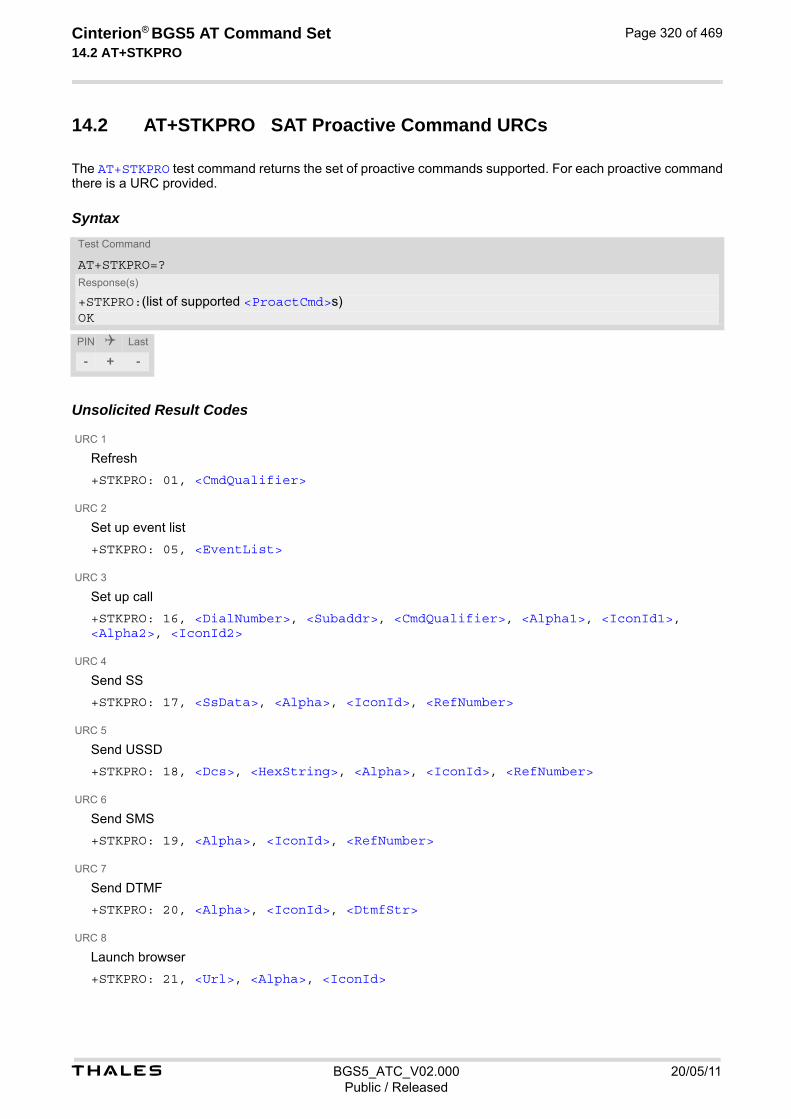
t BGS5_ATC_V02.000 20/05/11Public / Released
Cinterion® BGS5 AT Command Set 14.2 AT+STKPRO
Page 320 of 469
14.2 AT+STKPRO SAT Proactive Command URCs
The AT+STKPRO test command returns the set of proactive commands supported. For each proactive command there is a URC provided.
Syntax
Unsolicited Result Codes
URC 1
Refresh
+STKPRO: 01, <CmdQualifier>
URC 2
Set up event list
+STKPRO: 05, <EventList>
URC 3
Set up call
+STKPRO: 16, <DialNumber>, <Subaddr>, <CmdQualifier>, <Alpha1>, <IconId1>, <Alpha2>, <IconId2>
URC 4
Send SS
+STKPRO: 17, <SsData>, <Alpha>, <IconId>, <RefNumber>
URC 5
Send USSD
+STKPRO: 18, <Dcs>, <HexString>, <Alpha>, <IconId>, <RefNumber>
URC 6
Send SMS
+STKPRO: 19, <Alpha>, <IconId>, <RefNumber>
URC 7
Send DTMF
+STKPRO: 20, <Alpha>, <IconId>, <DtmfStr>
URC 8
Launch browser
+STKPRO: 21, <Url>, <Alpha>, <IconId>
Test Command
AT+STKPRO=?Response(s)
+STKPRO:(list of supported <ProactCmd>s)OK
PIN Last
- + -

t BGS5_ATC_V02.000 20/05/11Public / Released
Cinterion® BGS5 AT Command Set 14.2 AT+STKPRO
Page 321 of 469
URC 9
Play tone
+STKPRO: 32, <Tone>, <TimeUnit>, <Interval>, <Alpha>, <IconId>
URC 10
Display text
+STKPRO: 33, <CmdQualifier>, <Dcs>, <HexString>, <IconId>
URC 11
Get inkey
+STKPRO: 34, <CmdQualifier>, <Dcs>, <HexString>, <IconId>
URC 12
Get input
+STKPRO: 35, <CmdQualifier>, <Dcs>, <HexString>, <MaxRespLen>, <MinRespLen>, <DefaultText>, <IconId>
URC 13
Select item
+STKPRO: 36, <CmdQualifier>, <Alpha>, <ItemId>, <TotalItems>, <ItemText>, <NextAction>, <DefaultItem>, <IconId>, <IconIdListElem>
URC 14
Set up menu
+STKPRO: 37, <CmdQualifier>, <Alpha>, <ItemId>, <TotalItems>, <ItemText>, <NextAction>, <IconId>, <IconIdListElem>
URC 15
Provide local information
+STKPRO: 38, <CmdQualifier>
URC 16
Set up idle mode text
+STKPRO: 40, <Dcs>, <HexString>, <IconId>
URC 17
Language notification
+STKPRO: 53, <Lang>
URC 18
Open channel
+STKPRO: 64, <CmdQualifier>, <Alpha>, <IconId>, <DialNumber>, <ReconInterval>, <ReconTimeUnit>, <IdleInterval>, <IdleUnit>, <BearerType>, <BearerParam>, <BufSize>, <LoginDcs>, <LoginText>, <PasswordDcs>, <PasswordText>, <TransportLevel>, <TransportPort>, <SubaddrCs>, <DestAddrType>, <DestAddr>
URC 19
Close channel
+STKPRO: 65, <CmdQualifier>, <Alpha>, <IconId>
URC 20
Receive data
+STKPRO: 66, <CmdQualifier>, <Alpha>, <IconId>, <ChannelID>, <ChannelDataLen>
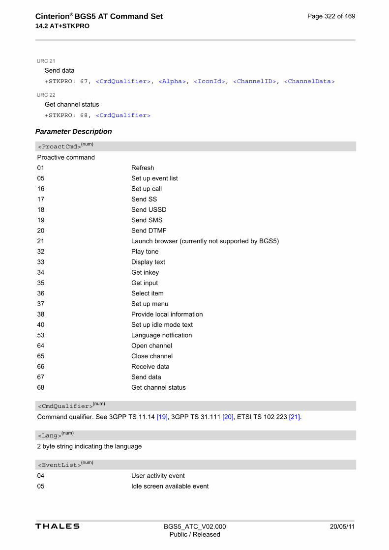
t BGS5_ATC_V02.000 20/05/11Public / Released
Cinterion® BGS5 AT Command Set 14.2 AT+STKPRO
Page 322 of 469
URC 21
Send data
+STKPRO: 67, <CmdQualifier>, <Alpha>, <IconId>, <ChannelID>, <ChannelData>
URC 22
Get channel status
+STKPRO: 68, <CmdQualifier> Parameter Description
Proactive command
01 Refresh
05 Set up event list
16 Set up call
17 Send SS
18 Send USSD
19 Send SMS
20 Send DTMF
21 Launch browser (currently not supported by BGS5)
32 Play tone
33 Display text
34 Get inkey
35 Get input
36 Select item
37 Set up menu
38 Provide local information
40 Set up idle mode text
53 Language notfication
64 Open channel
65 Close channel
66 Receive data
67 Send data
68 Get channel status
Command qualifier. See 3GPP TS 11.14 [19], 3GPP TS 31.111 [20], ETSI TS 102 223 [21].
2 byte string indicating the language
04 User activity event
05 Idle screen available event
<ProactCmd>(num)
<CmdQualifier>(num)
<Lang>(num)
<EventList>(num)

t BGS5_ATC_V02.000 20/05/11Public / Released
Cinterion® BGS5 AT Command Set 14.2 AT+STKPRO
Page 323 of 469
07 Language selection
08 Browser Termination event
Called party number
Called party subaddress
Text string
Text string
Text string
Icon Identifier
Icon Identifier
Icon Identifier
Icon ID list element
Data string
Reference number
DTMF string
01 Dial tone
02 Call subscriber busy
03 Congestion
04 Radio path acknowledge
05 Radio path not available
<DialNumber>(num)
<Subaddr>(num)
<Alpha>(str)
<Alpha1>(str)
<Alpha2>(str)
<IconId>(num)
<IconId1>(num)
<IconId2>(num)
<IconIdListElem>(num)
<SsData>(str)
<RefNumber>(num)
<DtmfStr>(str)
<Tone>(num)

t BGS5_ATC_V02.000 20/05/11Public / Released
Cinterion® BGS5 AT Command Set 14.2 AT+STKPRO
Page 324 of 469
06 Error / special information
07 Call waiting tone
08 Ringing tone
10 General beep
11 Positive acknowledgement tone
12 Negative acknowledgement or error tone
Time duration in number of time units
0 Indicates a non-existing duration object
1...255 Multiples of <TimeUnit>
0 Minutes
1 Seconds
2 Tenth of seconds
Defines the duration when an idle connection is released automatically. If not present, the ME never shall release a connection automatically.
0 Indicates a non-existing duration object
1...255 Multiples of <IdleUnit>
0 Minutes
1 Seconds
2 Tenth of seconds
A duration for reconnect tries. The interval specifies the time interval of the duration in multiples of the reconnect time unit used.
0 Indicates a non-existing duration object
1...255 Multiples of <ReconTimeUnit>
0 Minutes
1 Seconds
2 Tenth of seconds
Total items
Item identifier (see 3GPP TS 11.14 [19], 3GPP TS 31.111 [20], ETSI TS 102 223 [21])
<Interval>(num)
<TimeUnit>(num)
<IdleInterval>(num)
<IdleUnit>(num)
<ReconInterval>(num)
<ReconTimeUnit>(num)
<TotalItems>(num)
<ItemId>(num)

t BGS5_ATC_V02.000 20/05/11Public / Released
Cinterion® BGS5 AT Command Set 14.2 AT+STKPRO
Page 325 of 469
Item text string
URL that shall be loaded
Text string
Default item, see <ItemId>
Data coding scheme
String containing data in hexadecimal format
Maximum response length
Minimum response length
Next action
1 Circuit switched
2 Packet switched
3 Default bearer
255 Invalid
Hex string containing detailed information dependent on the type.
The buffer the TE shall allocate for channel data.
Data coding scheme of the text string. Text strings may be coded in 7-bit, 8-bit or UCS2 (16-bit) for user authen-tication data if requested by the bearer connection.
Specifies user authentication data if requested by the bearer connection. Coding based on <LoginDcs>.
<ItemText>(num)
<Url>(str)
<DefaultText>(str)
<DefaultItem>(str)
<Dcs>(str)
<HexString>(str)
<MaxRespLen>(num)
<MinRespLen>(num)
<NextAction>(num)
<BearerType>(num)
<BearerParam>(num)
<BufSize>(num)
<LoginDcs>(str)
<LoginText>(str)
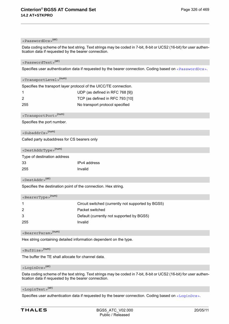
t BGS5_ATC_V02.000 20/05/11Public / Released
Cinterion® BGS5 AT Command Set 14.2 AT+STKPRO
Page 326 of 469
Data coding scheme of the text string. Text strings may be coded in 7-bit, 8-bit or UCS2 (16-bit) for user authen-tication data if requested by the bearer connection.
Specifies user authentication data if requested by the bearer connection. Coding based on <PasswordDcs>.
Specifies the transport layer protocol of the UICC/TE connection.
1 UDP (as defined in RFC 768 [9])
2 TCP (as defined in RFC 793 [10]
255 No transport protocol specified
Specifies the port number.
Called party subaddress for CS bearers only
Type of destination address
33 IPv4 address
255 Invalid
Specifies the destination point of the connection. Hex string.
1 Circuit switched (currently not supported by BGS5)
2 Packet switched
3 Default (currently not supported by BGS5)
255 Invalid
Hex string containing detailed information dependent on the type.
The buffer the TE shall allocate for channel data.
Data coding scheme of the text string. Text strings may be coded in 7-bit, 8-bit or UCS2 (16-bit) for user authen-tication data if requested by the bearer connection.
Specifies user authentication data if requested by the bearer connection. Coding based on <LoginDcs>.
<PasswordDcs>(str)
<PasswordText>(str)
<TransportLevel>(num)
<TransportPort>(num)
<SubaddrCs>(num)
<DestAddrType>(num)
<DestAddr>(str)
<BearerType>(num)
<BearerParam>(num)
<BufSize>(num)
<LoginDcs>(str)
<LoginText>(str)
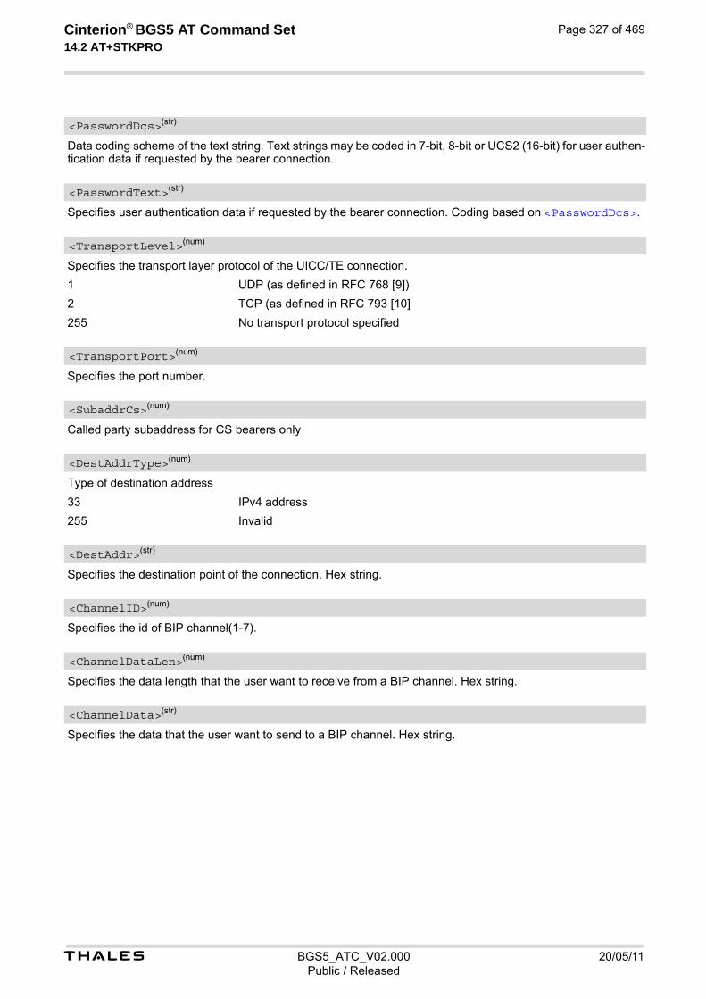
t BGS5_ATC_V02.000 20/05/11Public / Released
Cinterion® BGS5 AT Command Set 14.2 AT+STKPRO
Page 327 of 469
Data coding scheme of the text string. Text strings may be coded in 7-bit, 8-bit or UCS2 (16-bit) for user authen-tication data if requested by the bearer connection.
Specifies user authentication data if requested by the bearer connection. Coding based on <PasswordDcs>.
Specifies the transport layer protocol of the UICC/TE connection.
1 UDP (as defined in RFC 768 [9])
2 TCP (as defined in RFC 793 [10]
255 No transport protocol specified
Specifies the port number.
Called party subaddress for CS bearers only
Type of destination address
33 IPv4 address
255 Invalid
Specifies the destination point of the connection. Hex string.
Specifies the id of BIP channel(1-7).
Specifies the data length that the user want to receive from a BIP channel. Hex string.
Specifies the data that the user want to send to a BIP channel. Hex string.
<PasswordDcs>(str)
<PasswordText>(str)
<TransportLevel>(num)
<TransportPort>(num)
<SubaddrCs>(num)
<DestAddrType>(num)
<DestAddr>(str)
<ChannelID>(num)
<ChannelDataLen>(num)
<ChannelData>(str)

t BGS5_ATC_V02.000 20/05/11Public / Released
Cinterion® BGS5 AT Command Set 14.3 AT+STKTR
Page 328 of 469
14.3 AT+STKTR SAT Terminal Response Commands
Each AT+STKTR write command allows entering the response to a SAT proactive command which was displayed by the URC +STKPRO. The AT+STKTR test command returns the list or proactive commands (see <ProactCmd> of AT+STKPRO. Note: Value 0 in some of the commands specified below stands for parameter "last command" which is obsolete, but not removed so far. For the general <Result>s 32, 33, 38, 52, 53, 55, 57 and 58, it is mandatory for the ME to provide a specific cause value by using the <AddResult> parameter (additional information). For others additional information will be ignored.
SyntaxTest Command
AT+STKTR=?Response(s)
+STKTR:(list of supported <ProactCmd>s)OK
Write Command
Refresh
AT+STKTR=01,<Result>[, <AddResult>]Response(s)
OKERROR+CME ERROR: <err>
Write Command
Set up event list
AT+STKTR=05,<Result>Response(s)
OKERROR+CME ERROR: <err>
Write Command
Set up call
AT+STKTR=16,<Result>[, <AddResult>]Response(s)
OKERROR+CME ERROR: <err>
Write Command
Send SS
AT+STKTR=17,<Result>[, <AddResult>]Response(s)
OKERROR+CME ERROR: <err>

t BGS5_ATC_V02.000 20/05/11Public / Released
Cinterion® BGS5 AT Command Set 14.3 AT+STKTR
Page 329 of 469
Write Command
Send USSD
AT+STKTR=18,<Result>[, <AddResult>, 0, <Dcs>, <HexString>]Response(s)
OKERROR+CME ERROR: <err>
Write Command
Send SMS
AT+STKTR=19,<Result>[, <AddResult>]Response(s)
OKERROR+CME ERROR: <err>
Write Command
Send DTMF
AT+STKTR=20,<Result>[, <AddResult>]Response(s)
OKERROR+CME ERROR: <err>
Write Command
Launch browser
AT+STKTR=21,<Result>Response(s)
OKERROR+CME ERROR: <err>
Write Command
Play tone
AT+STKTR=32,<Result>[, <AddResult>]Response(s)
OKERROR+CME ERROR: <err>
Write Command
Display text
AT+STKTR=33,<Result>[, <AddResult>]Response(s)
OKERROR+CME ERROR: <err>
Write Command
Get inkey
AT+STKTR=34,<Result>, <AddResult>, 0, <Dcs>, <HexString>Response(s)
OK

t BGS5_ATC_V02.000 20/05/11Public / Released
Cinterion® BGS5 AT Command Set 14.3 AT+STKTR
Page 330 of 469
ERROR+CME ERROR: <err>
Write Command
Get input
AT+STKTR=35,<Result>, <AddResult>, 0, <Dcs>, <HexString>Response(s)
OKERROR+CME ERROR: <err>
Write Command
Select item
AT+STKTR=36,<Result>, <AddResult>, 0, <Dcs>, <HexString>Response(s)
OKERROR+CME ERROR: <err>
Write Command
Set up menu
AT+STKTR=37,<Result>[, <AddResult>]Response(s)
OKERROR+CME ERROR: <err>
Write Command
Provide local information (generic)
AT+STKTR=38,<Result>, <AddResult>Response(s)
OKERROR+CME ERROR: <err>
Write Command
Provide local information: Set language
AT+STKTR=38,<Result>, <Lang>Response(s)
OKERROR+CME ERROR: <err>
Write Command
Set up idle mode text
AT+STKTR=40,<Result>[, <AddResult>]Response(s)
OKERROR+CME ERROR: <err>
Write Command (Continued)
Get inkey
AT+STKTR=34,<Result>, <AddResult>, 0, <Dcs>, <HexString>Response(s)

t BGS5_ATC_V02.000 20/05/11Public / Released
Cinterion® BGS5 AT Command Set 14.3 AT+STKTR
Page 331 of 469
Write Command
Language notification
AT+STKTR=53,<Result>, <Lang>Response(s)
OKERROR+CME ERROR: <err>
Write Command
Open channel
AT+STKTR=64,<Result>Response(s)
OKERROR+CME ERROR: <err>
Write Command
Close channel
AT+STKTR=65,<Result>Response(s)
OKERROR+CME ERROR: <err>
Write Command
Receive data
AT+STKTR=66,<Result>Response(s)
OKERROR+CME ERROR: <err>
Write Command
Send data
AT+STKTR=67,<Result>Response(s)
OKERROR+CME ERROR: <err>
Write Command
Get channel status
AT+STKTR=68,<Result>Response(s)
OKERROR+CME ERROR: <err>
PIN Last
± + -

t BGS5_ATC_V02.000 20/05/11Public / Released
Cinterion® BGS5 AT Command Set 14.3 AT+STKTR
Page 332 of 469
Parameter Description
Decimal code that specifies the proactive command. See AT+STKPRO.
Result indicated as decimal code
0 Command performed successfully
1 Command performed with partial comprehension
2 Command performed with missing information
3 REFRESH performed with additional Efs read
4 Command performed successfully, but requested icon could not be displayed
5 Command performed but modified by call control by SIM
6 Command performed successfully, limited service
7 Launch browser
16 Proactive SIM session terminated by the user
17 Backward move in the proactive SIM session requested by the user
18 No response from user
19 Help information required by the user
20 USSD or SS transaction terminated by the user
32 ME currently unable to process command
33 Network currently unable to process the command
34 User did not accept call set-up request
35 User cleared down call before connection or network release
36 Action in contradiction with the current timer state
37 Interaction with call control by SIM, temporary problem
38 Launch browser generic error code
48 Command beyond ME's capabilities
49 Command type not understood by ME
50 Command data not understood by ME
51 Command number not known by ME
52 SS return error
53 SMS RP-ERROR
54 Error, required values are missing
55 USSD return error
57 Interaction with call control by SIM or MO short message control by SIM, per-manent problem
58 Bearer independent protocol error (if class "e" is supported)
Additional result
1...255 See 3GPP TS 11.14 [19], 3GPP TS 31.111 [20], ETSI TS 102 223 [21].
Item identifier (see 3GPP TS 11.14 [19], 3GPP TS 31.111 [20], ETSI TS 102 223 [21])
<ProactCmd>(num)
<Result>(num)
<AddResult>(num)
<ItemId>(num)

t BGS5_ATC_V02.000 20/05/11Public / Released
Cinterion® BGS5 AT Command Set 14.3 AT+STKTR
Page 333 of 469
Data Coding scheme. See 3GPP TS 23.038 [33].
String in hexadecimal format
Language given as integer (e.g. 28261 = English)
<Dcs>(num)
<HexString>(str)
<Lang>(num)

t BGS5_ATC_V02.000 20/05/11Public / Released
Cinterion® BGS5 AT Command Set 14.4 AT+STKENV
Page 334 of 469
14.4 AT+STKENV SAT Envelope Command
AT+STKENV allows to send an envelope command from the ME or TE to the SIM Application.
Syntax
Parameter Description
Decimal code that specifies the envelope command.
211 Menu selection
214 Event download
Item identifier
Optional parameter for <Event>= 08 Browser termination
0 User termination
1 Error termination
Optional parameter for <EnvCmd> 211
0 Help is requested
1 Help is not requested
Test Command
AT+STKENV=?Response(s)
+STKENV:(list of supported <EnvCmd>s)OK
Write Command
Menu Selection
AT+STKENV=211,<ItemId>[, <Help>]Response(s)
OKERROR+CME ERROR: <err>
Write Command
Event download
AT+STKENV=214,<Event>[, <Cause>]Response(s)
OKERROR+CME ERROR: <err>
PIN Last
± + -
<EnvCmd>(num)
<ItemId>(num)
<Cause>(num)
<Help>(num)

t BGS5_ATC_V02.000 20/05/11Public / Released
Cinterion® BGS5 AT Command Set 14.4 AT+STKENV
Page 335 of 469
01 Call connected event
04 User activity event
05 Idle screen available event
07 Language selection
08 Browser termination event (currently not supported by BGS5)
<Event>(num)

t BGS5_ATC_V02.000 20/05/11Public / Released
Cinterion® BGS5 AT Command Set 14.5 AT+STKCC
Page 336 of 469
14.5 AT+STKCC SAT Call Control Notification
The +STKCC URC reports the status call control activities:
Unsolicited Result Codes
URC 1
Reported activity: Set up call
+STKCC: 1, <ResVal>, <Alpha>, <PhoneNumber>, <NumberType>
URC 2
Reported activity: Send Supplementary Service commmand
+STKCC: 2, <ResVal>, <Alpha>, <SsCode>
URC 3
Reported activity: Send USSD commmand
+STKCC: 3, <ResVal>, <Alpha>, <UssdCode>
URC 4
Reported activity: Send short message
+STKCC: 4, <ResVal>, <Alpha>, <ToSca>, <Sca>, <ToRa>, <Ra> Parameter Description
Call control result value
0 Allowed
1 Not allowed
2 Allowed, with modification
254 SAT busy (status word SW=x9300)
Optional information provided by the SIM as text string
Called party phone number
0...255 Type of number (ton) and numbering plan identifier (npi), e.g. 129 for national number, 145 for international number
Supplementary Service code
USSD code
<ResVal>(num)
<Alpha>(num)
<PhoneNumber>(str)
<NumberType>(num)
<SsCode>(str)
<UssdCode>(str)

t BGS5_ATC_V02.000 20/05/11Public / Released
Cinterion® BGS5 AT Command Set 14.5 AT+STKCC
Page 337 of 469
0...255 Type of number (ton) and numbering plan identifier (npi) of Service Center address, e.g. 129 for national number, 145 for international number
Service Center Address
0...255 Type of number (ton) and numbering plan identifier (npi) of Recipient address, e.g. 129 for national number, 145 for international number
Recipient Address
<ToSca>(num)
<Sca>(num)
<ToRa>(num)
<Ra>(str)
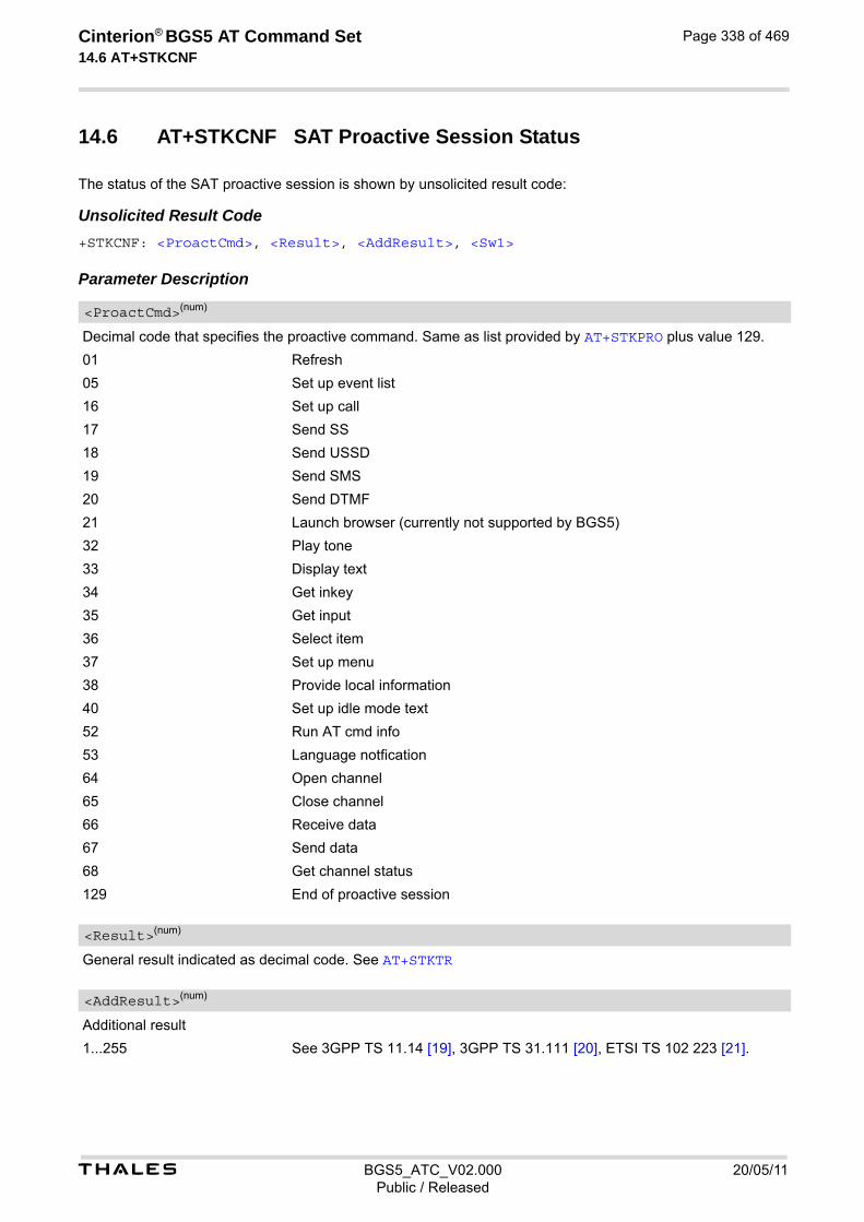
t BGS5_ATC_V02.000 20/05/11Public / Released
Cinterion® BGS5 AT Command Set 14.6 AT+STKCNF
Page 338 of 469
14.6 AT+STKCNF SAT Proactive Session Status
The status of the SAT proactive session is shown by unsolicited result code:
Unsolicited Result Code+STKCNF: <ProactCmd>, <Result>, <AddResult>, <Sw1> Parameter Description
Decimal code that specifies the proactive command. Same as list provided by AT+STKPRO plus value 129.
01 Refresh
05 Set up event list
16 Set up call
17 Send SS
18 Send USSD
19 Send SMS
20 Send DTMF
21 Launch browser (currently not supported by BGS5)
32 Play tone
33 Display text
34 Get inkey
35 Get input
36 Select item
37 Set up menu
38 Provide local information
40 Set up idle mode text
52 Run AT cmd info
53 Language notfication
64 Open channel
65 Close channel
66 Receive data
67 Send data
68 Get channel status
129 End of proactive session
General result indicated as decimal code. See AT+STKTR
Additional result
1...255 See 3GPP TS 11.14 [19], 3GPP TS 31.111 [20], ETSI TS 102 223 [21].
<ProactCmd>(num)
<Result>(num)
<AddResult>(num)
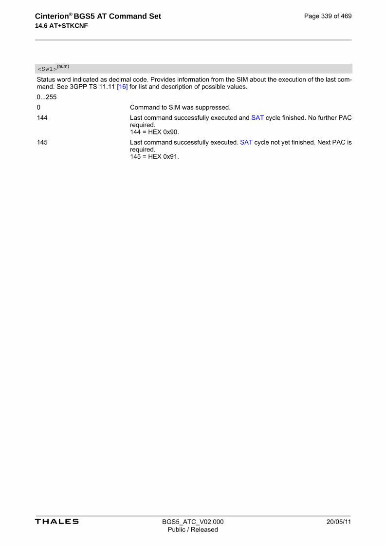
t BGS5_ATC_V02.000 20/05/11Public / Released
Cinterion® BGS5 AT Command Set 14.6 AT+STKCNF
Page 339 of 469
Status word indicated as decimal code. Provides information from the SIM about the execution of the last com-mand. See 3GPP TS 11.11 [16] for list and description of possible values.
0...255
0 Command to SIM was suppressed.
144 Last command successfully executed and SAT cycle finished. No further PAC required. 144 = HEX 0x90.
145 Last command successfully executed. SAT cycle not yet finished. Next PAC is required. 145 = HEX 0x91.
<Sw1>(num)

t BGS5_ATC_V02.000 20/05/11Public / Released
Cinterion® BGS5 AT Command Set 14.7 Examples of how to Configure and Use the SAT
Page 340 of 469
14.7 Examples of how to Configure and Use the SAT
Below you can find selective examples of how to configure and use the SAT Toolkit if Explicit Response (ER) mode is enabled with AT^SSTA.
Examples EXAMPLE 1
EXAMPLE 2
SET UP MENU
EXAMPLE 3
DISPLAY TEXT
EXAMPLE 4
GET INKEY
AT^SSTA=1 Set Explicit Response (ER) mode.OKAT^SMSO Switch off and restart the ME to make the change
take effect. ^SMSO: MS OFFOK^SHUTDOWN^SYSLOADING^SYSSTARTAT+CPIN="1234" Entering SIM PIN.OK
+STKPRO: 37,0,"Special",1,3,"News",0,0,0 +STKPRO URC displays menu structure. +STKPRO: 37,0,"Special",2,3,"EMail",0,0,0+STKPRO: 37,0,"Special",3,3,"Bank-ing",0,0,0AT+STKTR=37,0 Sending terminal response command for PAC 37. OK+STKCNF: 37,0,255,144 +STKCNF URC confirms that command was suc-
cessfully executed and SAT cycle has finished. No further PAC required.
AT+STKENV=211,2 Sending envelope command for selecting "EMail" option.
OK+STKCNF: 129, 0, 255, 144 +STKCNF URC indicates end of proactive session,
confirms that last command was successfully exe-cuted and SAT cycle has finished. No further PAC required.
+STKPRO: 33,128,4,"546F6F6C6B697420546573742031",0
+STKPRO URC indicates that PAC = 33 (Display text) is received. The sample text given in hexadeci-mal format means "Toolkit Test 1".
AT+STKTR=33,0 Sending terminal response command for PAC 33. OK+STKCNF: 33,0,255,144 +STKCNF URC confirms that command was suc-
cessfully executed and SAT cycle has finished. No further PAC required.
+STKPRO: 34,0,4,"456E74657220222B22",0 +STKPRO URC indicates that PAC = 34 (Get inkey) is received. The text given in hexadecimal format means that "Enter +" is requested.
AT+STKTR=34,0,0,0,4,"2B" Terminal response command for PAC 34 is sending "+" as HEX string "2B".

t BGS5_ATC_V02.000 20/05/11Public / Released
Cinterion® BGS5 AT Command Set 14.7 Examples of how to Configure and Use the SAT
Page 341 of 469
EXAMPLE 5
GET INPUT
OK+STKCNF: 34,0,255,144 +STKCNF URC confirms that command was suc-
cessfully executed and SAT cycle has finished. No further PAC required.
+STKPRO: 35,0,4,"456E746572203132333435",5,5,"",0
+STKPRO URC indicates that PAC = 35 (Get input) is received. The text given in hexadecimal format means that "Enter 12345" is requested.
AT+STKTR=35,0,0,0,4,"3132333435" Terminal response command for PAC 35 is sending "12345" as HEX string "3132333435".
OK+STKCNF: 34,0,255,144 +STKCNF URC confirms that command was suc-
cessfully executed and SAT cycle has finished. No further PAC required.

Cinterion® BGS5 AT Command Set 15. Phonebook Commands
t BGS5_ATC_V02.000 20/05/11Public / Released
Page 342 of 469
15. Phonebook Commands
The AT commands described in this chapter allow the external application to access the phonebooks located in the BGS5's memory or on the attached Subscriber Identity Module (SIM).
15.1 AT+CNUM Read own numbers
AT+CNUM returns the subscribers own number(s) from the SIM.
Syntax
Parameter Description
Optional alphanumeric string associated with <number>.
Phone number in format specified by <type>.
Type of address octet, see also: AT+CPBR <type>.
Test Command
AT+CNUM=?Response(s)
OK
Exec Command
AT+CNUMResponse(s)
[+CNUM: [<alpha>], <number>, <type>][+CNUM: ... ]OKERROR+CME ERROR: <err>
PIN Last Reference(s)
+ + - 3GPP TS 27.007 [43]
<alpha>(str)
<number>(str)
<type>(num)

t BGS5_ATC_V02.000 20/05/11Public / Released
Cinterion® BGS5 AT Command Set 15.2 AT+CPBR
Page 343 of 469
15.2 AT+CPBR Read from Phonebook
AT+CPBR serves to read one or more entries from the phonebook selected with AT command AT+CPBS. The AT+CPBR test command returns the location range supported by the current phonebook storage, the maxi-mum length of <number> field and the maximum length of <text> field. Note: Length information may not be available while SIM storage is selected. If storage does not offer format information, the format list contains empty parenthesizes. The AT+CPBR write command determines the phonebook entry to be displayed with <location1> or a location range from <location1> to <location2>. Hence, if no <location2> is given only the entry at <location1> will be displayed. If no entries are found at the selected location "OK" will be returned.
Syntax
Parameter Description
The first (lowest) location number within phonebook memory where to start reading. The maximum range sup-ported by the current phonebook is given in the test command response. If <location1> exceeds the upper bound <maxloc> (as indicated by the test command), command will respond with "+CME ERROR: invalid index".
The last (highest) location number within phonebook memory where to stop reading. The maximum range sup-ported by the current phonebook is given in the test command response. If both <location1> and <location2> are in the range indicated by the test command parameter <max-loc>, the list of entries will be output and terminated with "OK". If <location2> exceeds the range indicated by the test command parameter <maxloc>, the list of entries will be output but terminated with "+CME ERROR: invalid index".
Test Command
AT+CPBR=?Response(s)
+CPBR: (1-<maxloc>), <nlength>, <tlength>OKERROR+CME ERROR: <err>
Write Command
AT+CPBR=<location1>[, <location2>]Response(s)
[+CPBR: <location1>, <number>, <type>, <text>][+CPBR: <location2>, <number>, <type>, <text>]OKERROR+CME ERROR: <err>
PIN Last Reference(s)
+ + - 3GPP TS 27.007 [43], 3GPP TS 24.008 [38], 3GPP TS 11.11 [16], 3GPP TS 31.101 [17], 3GPP TS 31.102 [18]
<location1>(num)
<location2>(num)
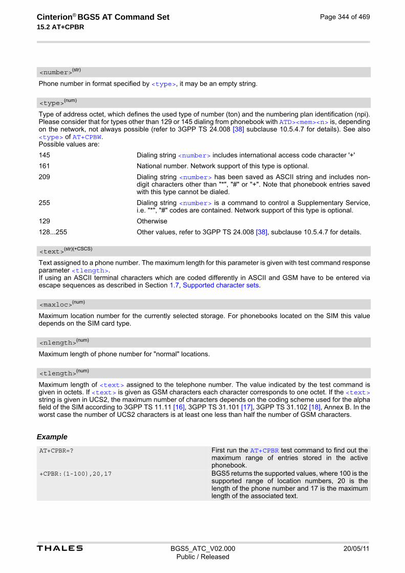
t BGS5_ATC_V02.000 20/05/11Public / Released
Cinterion® BGS5 AT Command Set 15.2 AT+CPBR
Page 344 of 469
Phone number in format specified by <type>, it may be an empty string.
Type of address octet, which defines the used type of number (ton) and the numbering plan identification (npi). Please consider that for types other than 129 or 145 dialing from phonebook with ATD><mem><n> is, depending on the network, not always possible (refer to 3GPP TS 24.008 [38] subclause 10.5.4.7 for details). See also <type> of AT+CPBW. Possible values are:
145 Dialing string <number> includes international access code character '+'
161 National number. Network support of this type is optional.
209 Dialing string <number> has been saved as ASCII string and includes non-digit characters other than "*", "#" or "+". Note that phonebook entries saved with this type cannot be dialed.
255 Dialing string <number> is a command to control a Supplementary Service, i.e. "*", "#" codes are contained. Network support of this type is optional.
129 Otherwise
128...255 Other values, refer to 3GPP TS 24.008 [38], subclause 10.5.4.7 for details.
Text assigned to a phone number. The maximum length for this parameter is given with test command response parameter <tlength>. If using an ASCII terminal characters which are coded differently in ASCII and GSM have to be entered via escape sequences as described in Section 1.7, Supported character sets.
Maximum location number for the currently selected storage. For phonebooks located on the SIM this value depends on the SIM card type.
Maximum length of phone number for "normal" locations.
Maximum length of <text> assigned to the telephone number. The value indicated by the test command is given in octets. If <text> is given as GSM characters each character corresponds to one octet. If the <text> string is given in UCS2, the maximum number of characters depends on the coding scheme used for the alpha field of the SIM according to 3GPP TS 11.11 [16], 3GPP TS 31.101 [17], 3GPP TS 31.102 [18], Annex B. In the worst case the number of UCS2 characters is at least one less than half the number of GSM characters.
Example
<number>(str)
<type>(num)
<text>(str)(+CSCS)
<maxloc>(num)
<nlength>(num)
<tlength>(num)
AT+CPBR=? First run the AT+CPBR test command to find out the maximum range of entries stored in the active phonebook.
+CPBR:(1-100),20,17 BGS5 returns the supported values, where 100 is the supported range of location numbers, 20 is the length of the phone number and 17 is the maximum length of the associated text.

t BGS5_ATC_V02.000 20/05/11Public / Released
Cinterion® BGS5 AT Command Set 15.2 AT+CPBR
Page 345 of 469
AT+CPBR =1,3 Then use the AT+CPBR write command to display the phonebook entries sorted by location numbers. +CPBR:1,"+999999",145,"Charlie"
+CPBR:2,"+777777",145,"Bill" +CPBR:3,"+888888",145,"Arthur"

t BGS5_ATC_V02.000 20/05/11Public / Released
Cinterion® BGS5 AT Command Set 15.3 AT+CPBS
Page 346 of 469
15.3 AT+CPBS Select phonebook memory storage
AT+CPBS selects the active phonebook storage, i.e. the phonebook storage that all subsequent phonebook com-mands will be operating on. Availability and capacity of phonebooks located on the SIM may vary depending on the provider and operator. The read command returns the currently selected <storage>, the number of <used> entries and the <total> number of entries available for this storage. The test command returns all supported <storage>s as compound value. The "SM" phonebook may or may not be available when FD lock is activated (see AT+CLCK), depending on the SIM and its configuration.
Syntax
Parameter Description
“SM“(P) SIM phonebook.
“FD“ SIM fixed dialing phonebook (EF_FDN). Requires PIN2 to be given using <password> or AT+CPIN2.
“SN“ SIM service dialing number phonebook (EF_SDN). Read only.
“LD“ SIM Last number Dialed phonebook. Stores all voice call numbers dialed with ATD, but no data call numbers. Read only.
“ON“ SIM MSISDN (Own Number) phonebook.
Test Command
AT+CPBS=?Response(s)
+CPBS: (list of supported <storage>s)OKERROR+CME ERROR: <err>
Read Command
AT+CPBS?Response(s)
+CPBS: <storage>, <used>, <total>OKERROR+CME ERROR: <err>
Write Command
AT+CPBS=<storage>[, <password>]Response(s)
OKERROR+CME ERROR: <err>
PIN Last Reference(s)
+ + - 3GPP TS 27.007 [43]
<storage>(str)
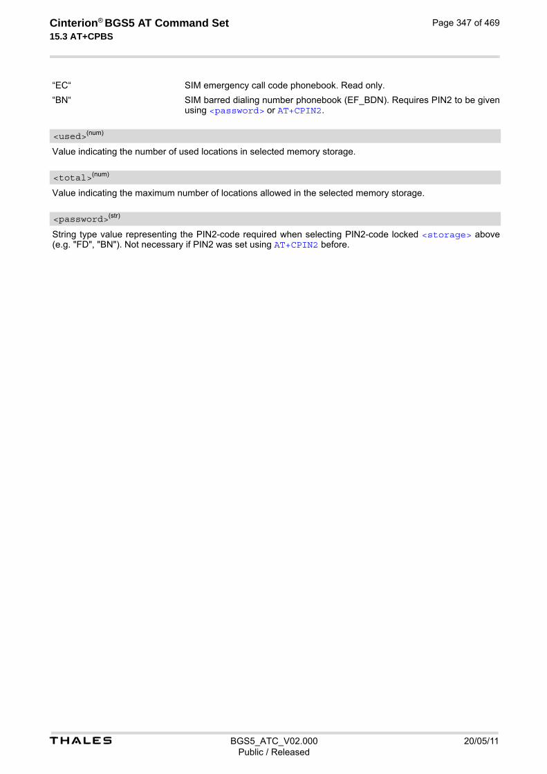
t BGS5_ATC_V02.000 20/05/11Public / Released
Cinterion® BGS5 AT Command Set 15.3 AT+CPBS
Page 347 of 469
“EC“ SIM emergency call code phonebook. Read only.
“BN“ SIM barred dialing number phonebook (EF_BDN). Requires PIN2 to be given using <password> or AT+CPIN2.
Value indicating the number of used locations in selected memory storage.
Value indicating the maximum number of locations allowed in the selected memory storage.
String type value representing the PIN2-code required when selecting PIN2-code locked <storage> above (e.g. "FD", "BN"). Not necessary if PIN2 was set using AT+CPIN2 before.
<used>(num)
<total>(num)
<password>(str)

t BGS5_ATC_V02.000 20/05/11Public / Released
Cinterion® BGS5 AT Command Set 15.4 AT+CPBW
Page 348 of 469
15.4 AT+CPBW Write into Phonebook
The AT+CPBW write command can be used to create, edit and delete a phonebook entry at a <location> of the active storage selected with AT+CPBS. The AT+CPBW test command returns the location range supported by the current storage, the maximum length of the <number> field, the range of supported <type> values and the maximum length of the <text> field. Note: The maximum <number> length may differ depending on SIM card, nevertheless <nlength> always presents the maximum possible value. In case of exceeding available number length, "+CME ERROR: Memory full" message is returned and the phonebook entry is not stored.
Syntax
Parameter Description
Location number within phonebook memory. The maximum range supported by each storage type is indicated in the test command response. If <location> is not given, the first free entry will be used. If <location> is given as the only parameter, the phonebook entry specified by <location> is deleted.
Phone number in format specified by <type>. Parameter must be present, although it may be an empty string. Alphabetic characters are not permitted. The <number> may contain dialstring modifiers "*", "#" or "+". However please note that entries containing *# codes cannot be stored together with international access code. For exam-ple, a dial string such as *31#+48123456789 can be dialed only by using the ATD command. If other printable non-alphabetic characters are used the entry needs to be saved with <type>=209. Otherwise, if <type>=209 is not used any non-digit characters other than "*", "#" or "+" will be removed from the string and only accepted modifiers from the GSM alphabet will be saved.
Test Command
AT+CPBW=?Response(s)
+CPBW: (1-<maxloc>), <nlength>, (list of supported <type>s), <tlength>OKERROR+CME ERROR: <err>
Write Command
AT+CPBW=[<location>][, <number>[[, <type>][, <text>]]]Response(s)
OKERROR+CME ERROR: <err>
PIN Last Reference(s)
+ + - 3GPP TS 27.007 [43], 3GPP TS 24.008 [38], 3GPP TS 11.11 [16], 3GPP TS 31.101 [17], 3GPP TS 31.102 [18]
<location>(num)
<number>(str)

t BGS5_ATC_V02.000 20/05/11Public / Released
Cinterion® BGS5 AT Command Set 15.4 AT+CPBW
Page 349 of 469
Type of address octet, which defines the used type of number (ton) and the numbering plan identification (npi). Please consider that for types other than 129 or 145 dialing from phonebook with ATD><mem><n> is, depending on the network, not always possible (refer to 3GPP TS 24.008 [38] subclause 10.5.4.7 for details). If <type> is not specified the unknown <type>=129 is used. If <number> contains a leading "+" <type>=145 (international) is used. Supported values are:
145 Dialing string <number> includes international access code character "+"
161 National number. The network support for this type is optional.
209 Dialing string <number> will be saved as ASCII string. This is the default value, if <type> is not specified explicitly and characters other than "*", "#" or "+" are included in <number>. Note that phonebook entries saved with this type cannot be dialed.
255 Dialing string <number> is a command to control a Supplementary Service, i.e. "*", "#" codes are contained. Network support of this type is optional.
129 Unknown number. If <type> is unknown and the <number> contains a lead-ing "+", then this sign is removed.
128...255 Other values, refer to 3GPP TS 24.008 [38], subclause 10.5.4.7 for details.
Text assigned to the phone number. The maximum length of this parameter is given in the test command response <tlength>. When using an ASCII terminal, characters which are coded differently in ASCII and GSM have to be entered via escape sequences as described in Section 1.7, Supported character sets.
Maximum number of locations supported by the currently selected storage. For phonebooks located on SIM, this value varies depending on the SIM card. See AT+CPBS for typical values.
Maximum length of phone number for "normal" locations. ME allows to store numbers with <nlength> but memory size for storing numbers on SIM card is only 10 bytes for each. That gives maximum number length 10 for <type>=209 and 20 for other types. If the stored number is longer than this maximum value the rest of the number is saved to extended memory which is common for other records. Storing numbers which take more than 10 bytes, can lead to filling up extended memory on SIM card. As a result, "+CME ERROR: Memory full" will be indicated.
Maximum length of <text> assigned to the telephone number. The value indicated by the test command is given in octets. If the <text> string is given in GSM characters, each character corresponds to one octet. If the <text> string is given in UCS2, the maximum number of characters depends on the coding scheme used for the alpha field of the SIM.
Examples EXAMPLE 1
Make a new phonebook entry at the first free location
EXAMPLE 2
Delete entry at location 1
<type>(num)
<text>(str)(+CSCS)
<maxloc>(num)
<nlength>(num)
<tlength>(num)
AT+CPBW=,"+431234567",145,"international"
AT+CPBW=1
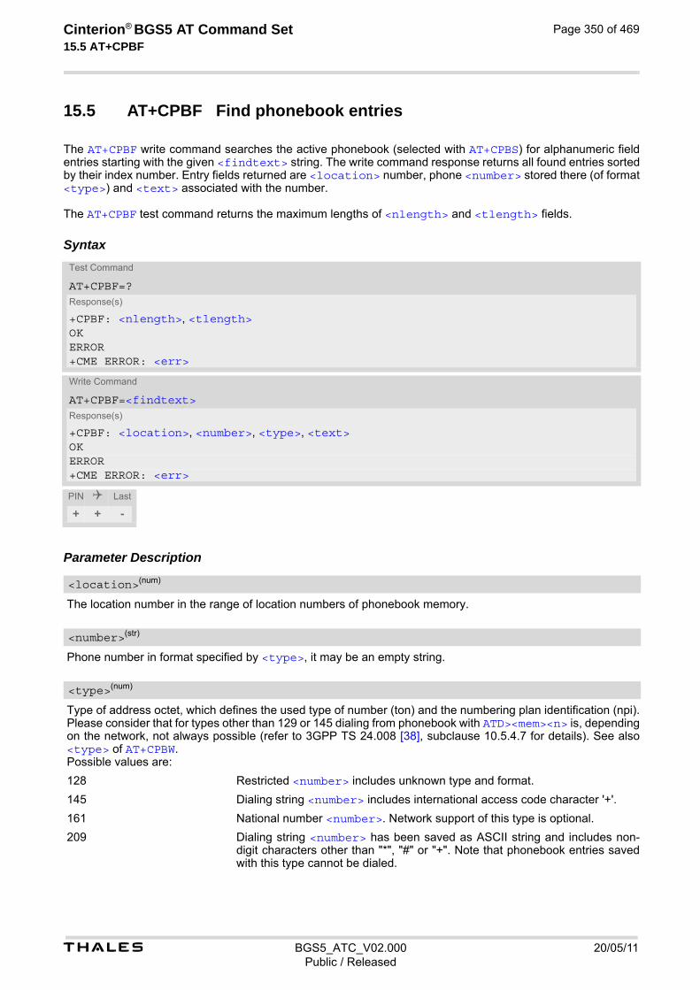
t BGS5_ATC_V02.000 20/05/11Public / Released
Cinterion® BGS5 AT Command Set 15.5 AT+CPBF
Page 350 of 469
15.5 AT+CPBF Find phonebook entries
The AT+CPBF write command searches the active phonebook (selected with AT+CPBS) for alphanumeric field entries starting with the given <findtext> string. The write command response returns all found entries sorted by their index number. Entry fields returned are <location> number, phone <number> stored there (of format <type>) and <text> associated with the number. The AT+CPBF test command returns the maximum lengths of <nlength> and <tlength> fields.
Syntax
Parameter Description
The location number in the range of location numbers of phonebook memory.
Phone number in format specified by <type>, it may be an empty string.
Type of address octet, which defines the used type of number (ton) and the numbering plan identification (npi). Please consider that for types other than 129 or 145 dialing from phonebook with ATD><mem><n> is, depending on the network, not always possible (refer to 3GPP TS 24.008 [38], subclause 10.5.4.7 for details). See also <type> of AT+CPBW. Possible values are:
128 Restricted <number> includes unknown type and format.
145 Dialing string <number> includes international access code character '+'.
161 National number <number>. Network support of this type is optional.
209 Dialing string <number> has been saved as ASCII string and includes non-digit characters other than "*", "#" or "+". Note that phonebook entries saved with this type cannot be dialed.
Test Command
AT+CPBF=?Response(s)
+CPBF: <nlength>, <tlength>OKERROR+CME ERROR: <err>
Write Command
AT+CPBF=<findtext>Response(s)
+CPBF: <location>, <number>, <type>, <text>OKERROR+CME ERROR: <err>
PIN Last
+ + -
<location>(num)
<number>(str)
<type>(num)

t BGS5_ATC_V02.000 20/05/11Public / Released
Cinterion® BGS5 AT Command Set 15.5 AT+CPBF
Page 351 of 469
255 Dialing string <number> is a command to control a Supplementary Service, i.e. "*", "#" codes are contained. Network support of this type is optional.
129 Otherwise.
Text assigned to a phone number. The maximum length for this parameter is given with test command response parameter <tlength>. If using an ASCII terminal characters which are coded differently in ASCII and GSM have to be entered via escape sequences as described in Section 1.7, Supported character sets.
String for finding the <text> in the active phonebook.
Maximum length of phone number for "normal" locations.
Maximum length of <text> assigned to the telephone number. The value indicated by the test command is given in octets. If <text> is given as GSM characters each character corresponds to one octet. If the <text> string is given in UCS2, the maximum number of characters depends on the coding scheme used for the alpha field of the SIM according to 3GPP TS 11.11 [16], 3GPP TS 31.101 [17], 3GPP TS 31.102 [18], Annex B. In the worst case the number of UCS2 characters is at least one less than half the number of GSM characters.
Example
<text>(str)(+CSCS)
<findtext>(str)(+CSCS)
<nlength>(num)
<tlength>(num)
AT+CPBF=? First run the AT+CPBF test command to find out the lengths of <nlength> and <tlength> in the active phonebook.
+CPBF: 40,16 BGS5 returns the supported values, where 40 is the maximum length of the phone number and 16 is the maximum length of the associated text.
AT+CPBF="cha" Then use the AT+CPBF write command to find any <text> string in the phonebook.
+CPBF:1,"+999999",145,"Charlie"
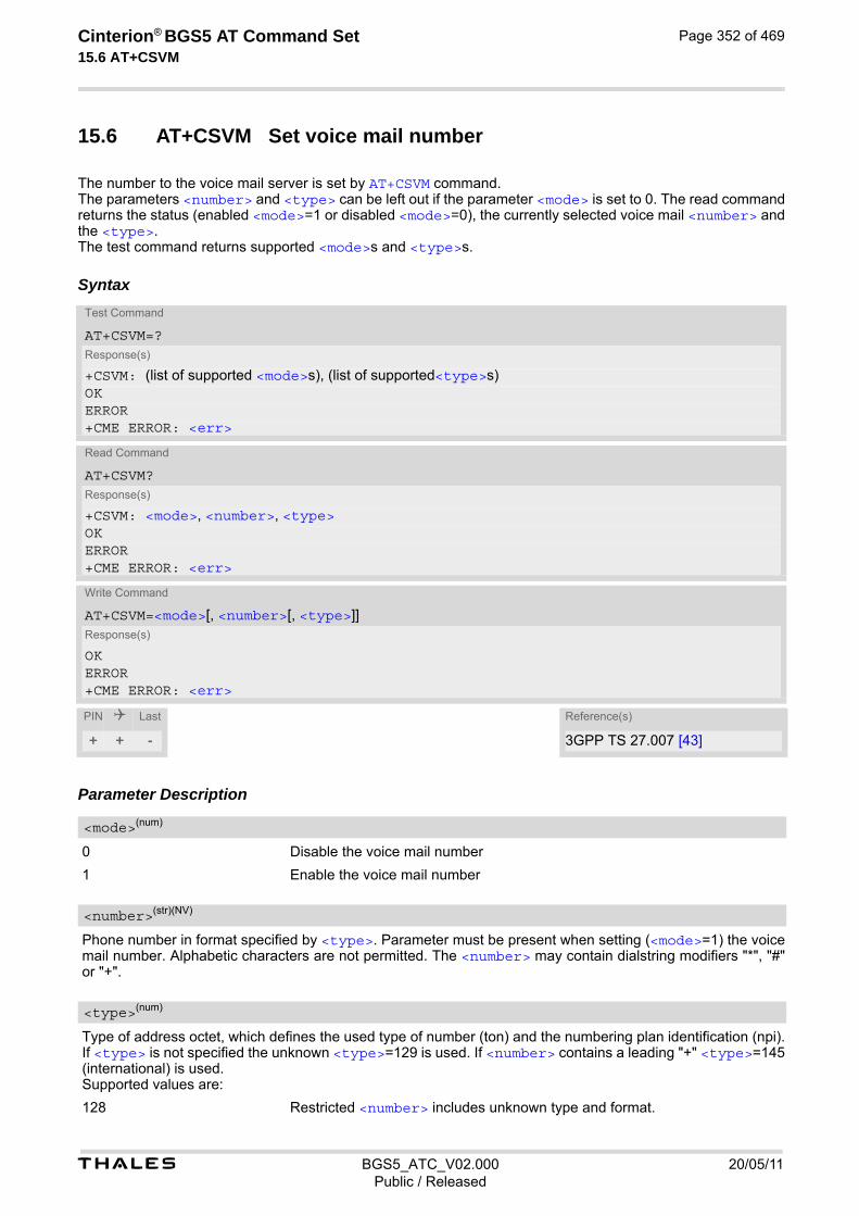
t BGS5_ATC_V02.000 20/05/11Public / Released
Cinterion® BGS5 AT Command Set 15.6 AT+CSVM
Page 352 of 469
15.6 AT+CSVM Set voice mail number
The number to the voice mail server is set by AT+CSVM command. The parameters <number> and <type> can be left out if the parameter <mode> is set to 0. The read command returns the status (enabled <mode>=1 or disabled <mode>=0), the currently selected voice mail <number> and the <type>. The test command returns supported <mode>s and <type>s.
Syntax
Parameter Description
0 Disable the voice mail number
1 Enable the voice mail number
Phone number in format specified by <type>. Parameter must be present when setting (<mode>=1) the voice mail number. Alphabetic characters are not permitted. The <number> may contain dialstring modifiers "*", "#" or "+".
Type of address octet, which defines the used type of number (ton) and the numbering plan identification (npi). If <type> is not specified the unknown <type>=129 is used. If <number> contains a leading "+" <type>=145 (international) is used. Supported values are:
128 Restricted <number> includes unknown type and format.
Test Command
AT+CSVM=?Response(s)
+CSVM: (list of supported <mode>s), (list of supported<type>s)OKERROR+CME ERROR: <err>
Read Command
AT+CSVM?Response(s)
+CSVM: <mode>, <number>, <type>OKERROR+CME ERROR: <err>
Write Command
AT+CSVM=<mode>[, <number>[, <type>]]Response(s)
OKERROR+CME ERROR: <err>
PIN Last Reference(s)
+ + - 3GPP TS 27.007 [43]
<mode>(num)
<number>(str)(NV)
<type>(num)
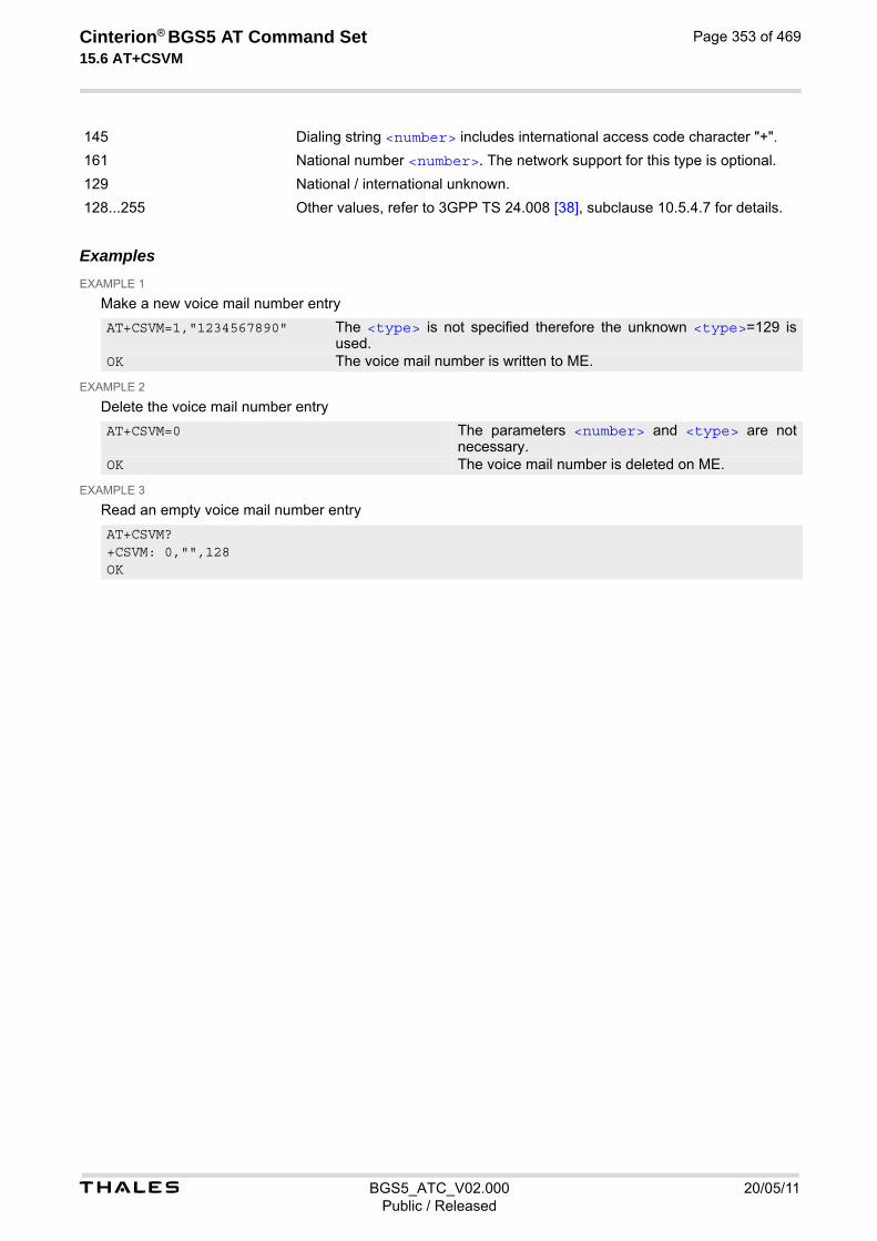
t BGS5_ATC_V02.000 20/05/11Public / Released
Cinterion® BGS5 AT Command Set 15.6 AT+CSVM
Page 353 of 469
145 Dialing string <number> includes international access code character "+".
161 National number <number>. The network support for this type is optional.
129 National / international unknown.
128...255 Other values, refer to 3GPP TS 24.008 [38], subclause 10.5.4.7 for details.
Examples EXAMPLE 1
Make a new voice mail number entry
EXAMPLE 2
Delete the voice mail number entry
EXAMPLE 3
Read an empty voice mail number entry
AT+CSVM=1,"1234567890" The <type> is not specified therefore the unknown <type>=129 is used.
OK The voice mail number is written to ME.
AT+CSVM=0 The parameters <number> and <type> are not necessary.
OK The voice mail number is deleted on ME.
AT+CSVM? +CSVM: 0,"",128 OK
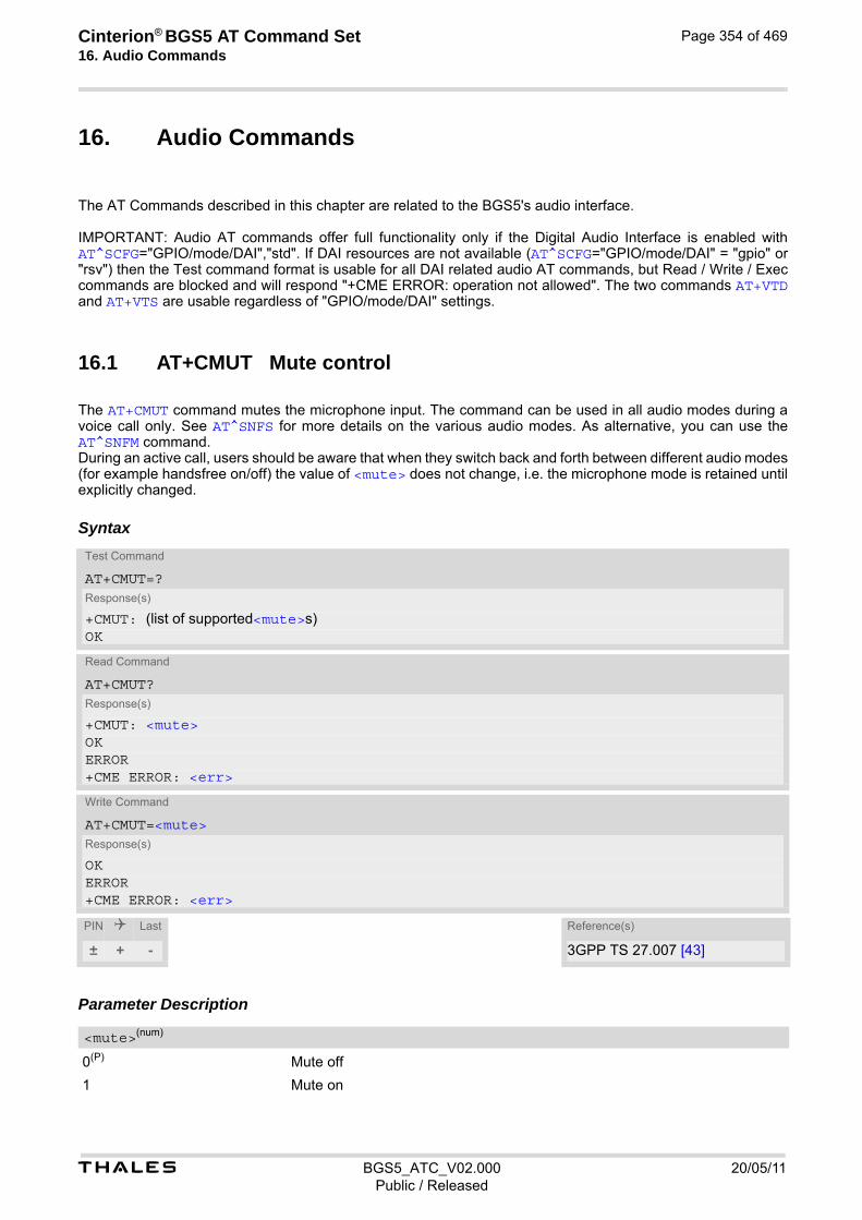
Cinterion® BGS5 AT Command Set 16. Audio Commands
t BGS5_ATC_V02.000 20/05/11Public / Released
Page 354 of 469
16. Audio Commands
The AT Commands described in this chapter are related to the BGS5's audio interface. IMPORTANT: Audio AT commands offer full functionality only if the Digital Audio Interface is enabled with AT^SCFG="GPIO/mode/DAI","std". If DAI resources are not available (AT^SCFG="GPIO/mode/DAI" = "gpio" or "rsv") then the Test command format is usable for all DAI related audio AT commands, but Read / Write / Exec commands are blocked and will respond "+CME ERROR: operation not allowed". The two commands AT+VTD and AT+VTS are usable regardless of "GPIO/mode/DAI" settings.
16.1 AT+CMUT Mute control
The AT+CMUT command mutes the microphone input. The command can be used in all audio modes during a voice call only. See AT^SNFS for more details on the various audio modes. As alternative, you can use the AT^SNFM command. During an active call, users should be aware that when they switch back and forth between different audio modes (for example handsfree on/off) the value of <mute> does not change, i.e. the microphone mode is retained until explicitly changed.
Syntax
Parameter Description
0(P) Mute off
1 Mute on
Test Command
AT+CMUT=?Response(s)
+CMUT: (list of supported<mute>s)OK
Read Command
AT+CMUT?Response(s)
+CMUT: <mute>OKERROR+CME ERROR: <err>
Write Command
AT+CMUT=<mute>Response(s)
OKERROR+CME ERROR: <err>
PIN Last Reference(s)
± + - 3GPP TS 27.007 [43]
<mute>(num)

t BGS5_ATC_V02.000 20/05/11Public / Released
Cinterion® BGS5 AT Command Set 16.2 AT+VTD
Page 355 of 469
16.2 AT+VTD Tone duration
This command refers to an integer <duration> that defines the length of tones transmitted with the AT+VTS command.
Syntax
Parameter Description
Duration of the DTMF signal in 1/10 seconds with tolerance.
1...5(P)...255
Test Command
AT+VTD=?Response(s)
+VTD: (list of supported<duration>s)OK
Read Command
AT+VTD?Response(s)
<duration>OKERROR+CME ERROR: <err>
Write Command
AT+VTD=<duration>Response(s)
OKERROR+CME ERROR: <err>
PIN Last Reference(s)
- - - 3GPP TS 27.007 [43]
<duration>(num)
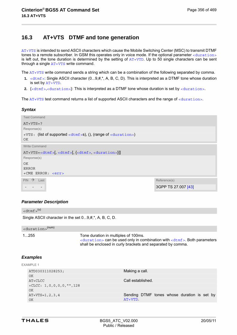
t BGS5_ATC_V02.000 20/05/11Public / Released
Cinterion® BGS5 AT Command Set 16.3 AT+VTS
Page 356 of 469
16.3 AT+VTS DTMF and tone generation
AT+VTS is intended to send ASCII characters which cause the Mobile Switching Center (MSC) to transmit DTMF tones to a remote subscriber. In GSM this operates only in voice mode. If the optional parameter <duration> is left out, the tone duration is determined by the setting of AT+VTD. Up to 50 single characters can be sent through a single AT+VTS write command. The AT+VTS write command sends a string which can be a combination of the following separated by comma.
1. <dtmf>: Single ASCII character (0...9,#,*, A, B, C, D). This is interpreted as a DTMF tone whose duration is set by AT+VTD.
2. {<dtmf>,<duration>}: This is interpreted as a DTMF tone whose duration is set by <duration>.
The AT+VTS test command returns a list of supported ASCII characters and the range of <duration>.
Syntax
Parameter Description
Single ASCII character in the set 0...9,#,*, A, B, C, D.
1...255 Tone duration in multiples of 100ms. <duration> can be used only in combination with <dtmf>. Both parameters shall be enclosed in curly brackets and separated by comma.
Examples EXAMPLE 1
Test Command
AT+VTS=?Response(s)
+VTS: (list of supported <dtmf>s), (), (range of <duration>)OK
Write Command
AT+VTS=<dtmf>[, <dtmf>[, {<dtmf>, <duration>}]]Response(s)
OKERROR+CME ERROR: <err>
PIN Last Reference(s)
- - - 3GPP TS 27.007 [43]
<dtmf>(u)
<duration>(num)
ATD030311028253; Making a call.OKAT+CLCC Call established.+CLCC: 1,0,0,0,0,"",128OKAT+VTS=1,2,3,4 Sending DTMF tones whose duration is set by
AT+VTD.OK

t BGS5_ATC_V02.000 20/05/11Public / Released
Cinterion® BGS5 AT Command Set 16.3 AT+VTS
Page 357 of 469
EXAMPLE 2
For compatibility with earlier BGS5 releases the entire AT+VTS write command string can optionally be set in quotation marks:
AT+VTS=A Sending one DTMF tone whose duration is set by AT+VTD.OK
AT+VTS={1,200},{B,254} Sending DTMF tones whose duration is set by <duration>.OK
AT+VTS=1,2,3,4,5,{1,200},{B,254} Combination of DTMF tones with duration set by AT+VTD and <duration>.OK
ATD030311028253; Making a call.OKAT+CLCC Call established.+CLCC: 1,0,0,0,0,"",128OKAT+VTS="1,2,3,4" Sending DTMF tones whose duration is set by
AT+VTD.OKAT+VTS="A" Sending one DTMF tone whose duration is set by
AT+VTD.OKAT+VTS="{1,200},{B,254}" Sending DTMF tones whose duration is set by
<duration>.OKAT+VTS="1,2,3,4,5,{1,200},{B,254}" Combination of DTMF tones with duration set by
AT+VTD and <duration>.OK

t BGS5_ATC_V02.000 20/05/11Public / Released
Cinterion® BGS5 AT Command Set 16.4 AT^SNFI
Page 358 of 469
16.4 AT^SNFI Set microphone path parameters
AT^SNFI controls the microphone path amplification. Read and write options of this command refer to the active audio mode. The write command works only in audio modes 2 to 10.
Syntax
Parameter Description
0...100 Microphone gain ranging from from -43.5 db to 6 dB, adjustable in steps of 0.5 dB. (0 = -96 dB, 1 = -43.5 dB, 88 = 0 dB, 99 = 5.5 dB, 100 = 6 dB).
Notes• The microphone mute status <MicSwitch> has no influence on value of <inVolStep>
• Attention! When you adjust audio parameters avoid exceeding the maximum allowed level. Bear in mind that exposure to excessive levels of noise can cause physical damage to users!
Test Command
AT^SNFI=?Response(s)
^SNFI: (list of supported <inVolStep>s)OK
Read Command
AT^SNFI?Response(s)
^SNFI: <inVolStep>OKERROR+CME ERROR: <err>
Write Command
AT^SNFI=<inVolStep>Response(s)
OKERROR+CME ERROR: <err>
PIN Last
- + -
<inVolStep>(num)
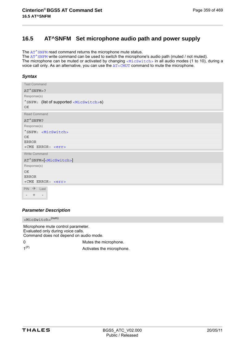
t BGS5_ATC_V02.000 20/05/11Public / Released
Cinterion® BGS5 AT Command Set 16.5 AT^SNFM
Page 359 of 469
16.5 AT^SNFM Set microphone audio path and power supply
The AT^SNFM read command returns the microphone mute status. The AT^SNFM write command can be used to switch the microphone's audio path (muted / not muted). The microphone can be muted or activated by changing <MicSwitch> in all audio modes (1 to 10), during a voice call only. As an alternative, you can use the AT+CMUT command to mute the microphone.
Syntax
Parameter Description
Microphone mute control parameter. Evaluated only during voice calls. Command does not depend on audio mode.
0 Mutes the microphone.
1(P) Activates the microphone.
Test Command
AT^SNFM=?Response(s)
^SNFM: (list of supported <MicSwitch>s) OK
Read Command
AT^SNFM?Response(s)
^SNFM: <MicSwitch>OKERROR+CME ERROR: <err>
Write Command
AT^SNFM=[<MicSwitch>]Response(s)
OKERROR+CME ERROR: <err>
PIN Last
- + -
<MicSwitch>(num)

t BGS5_ATC_V02.000 20/05/11Public / Released
Cinterion® BGS5 AT Command Set 16.6 AT^SNFO
Page 360 of 469
16.6 AT^SNFO Set audio output (= loudspeaker path) parameter
AT^SNFO controls the earpiece path amplification. The read and write commands refer to the active audio mode. The write command works only in audio modes 2 to 10.
Syntax
Parameter Description
0...100 Speaker gain ranging from -43.5 dB to 6 dB, adjustable in steps of 0.5 dB. (0 = -96 dB, 1 = -43.5 dB, 88 = 0 dB, 99 = 5.5 dB, 100 = 6 dB).
0...175 Sidetone gain ranging from -43.5 dB to 43.5 dB, adjustable in steps 0.5 dB. (0 = -96 dB, 175 = 43.5 dB)
Note• CAUTION! When you adjust audio parameters avoid exceeding the maximum allowed level. Bear in mind that
exposure to excessive levels of noise can cause physical damage to users!
Test Command
AT^SNFO=?Response(s)
^SNFO: (list of supported <outVolStep>s), (list of supported <sideToneStep>s)OK
Read Command
AT^SNFO?Response(s)
^SNFO: <outVolStep>, <sideToneStep>OKERROR+CME ERROR: <err>
Write Command
AT^SNFO=<outVolStep>, <sideToneStep>Response(s)
OKERROR+CME ERROR: <err>
PIN Last
- + -
<outVolStep>(num)
<sideToneStep>(num)

t BGS5_ATC_V02.000 20/05/11Public / Released
Cinterion® BGS5 AT Command Set 16.7 AT^SNFS
Page 361 of 469
16.7 AT^SNFS Select audio hardware set
The AT^SNFS write command serves to set the audio mode required for the connected equipment.
Syntax
Parameter Description
1 Audio mode 1: Standard mode optimized reference handset that can be con-nected to the digital audio interface. Note: The default parameters are determined for type approval and are not adjustable with AT commands.
2 Audio mode 2: For a basic handsfree (speakerphone) device (Siemens Car Kit Portable).
3 Audio mode 3: For mono-headset.
4 Audio mode 4: For individual handset.
5 Audio mode 5: Customer specific mode.
6 Audio mode 6: Customer specific mode.
7 Audio mode 7: Customer specific mode.
8 Audio mode 8: Customer specific mode.
9 Audio mode 9: Customer specific mode.
10(D) Audio mode 10: Transparent mode.
Test Command
AT^SNFS=?Response(s)
^SNFS: (list of supported <audMode>s) OK
Read Command
AT^SNFS?Response(s)
^SNFS: <audMode>OKERROR+CME ERROR: <err>
Write Command
AT^SNFS=<audMode>Response(s)
OKERROR+CME ERROR: <err>
PIN Last
- + -
<audMode>(num)
t BGS5_ATC_V02.000 20/05/11Public / Released
Cinterion® BGS5 AT Command Set 16.7 AT^SNFS
Page 362 of 469
Notes• The write command can be used during a voice call to switch back and forth between different modes. This
allows the user, for example, to switch handsfree operation (speakerphone) on and off.
• Audio modes from 5 to 9 are customer modes that can be prepared for specific customer requirements.
• The default audio mode is active each time the module is powered up.

t BGS5_ATC_V02.000 20/05/11Public / Released
Cinterion® BGS5 AT Command Set 16.8 AT^SRTC
Page 363 of 469
16.8 AT^SRTC Ring tone configuration
The AT^SRTC read command returns the current <type> and current <volume>. The read command can be used while test playback is off or on. In the latter case, see execute command for details. The AT^SRTC execute command is intended only for testing. It starts to play a melody from the audio output cur-rently selected with AT^SNFS. To deactivate test playback use AT^SRTC again. During test playback, you can enter the write command to select another melody and adjust the volume. Also, you can enter the read command to check the type and volume of the current ring tone, and to view the status of playback (on / off). The AT^SRTC write command chooses the type and volume of ring tones. The selected <type> and <volume> are stored non-volatile. The only exception is <type>=0 which is not stored because it is intended only to quickly stop the tone currently played. So <type>=0 only stops immediately the audible ring tone, but does not terminate the RING URC. In this case the AT^SRTC write command returns only OK.
Syntax
Test Command
AT^SRTC=?Response(s)
^SRTC:(list of supported) <type>s, (list of supported) <volume>sOK
Read Command
AT^SRTC?Response(s)
^SRTC: <type>, <volume>, <status>OKERROR+CME ERROR: <err>
Exec Command
AT^SRTCResponse(s)
OKERROR+CME ERROR: <err>
Write Command
AT^SRTC=<type>[, <volume>]Response(s)
^SRTC: <type>, <volume>OKERROR+CME ERROR: <err>
PIN Last
- + -

t BGS5_ATC_V02.000 20/05/11Public / Released
Cinterion® BGS5 AT Command Set 16.8 AT^SRTC
Page 364 of 469
Parameter Description
Type of ring tone. You have a choice of 8 different ring tones and melodies. All will be played from the audio output selected with the AT^SNFS command. <type>=0 is only intended for stopping of current ringtone play-back.
0 Stops the currently played tone immediately
1 Sequence 1
2 Sequence 2
3(D) Sequence 3
4 Sequence 4
5 Sequence 5
6 Sequence 6
7 Sequence 7
8 Sequence 8
Volume of ring tone, varies from low to high.
0(D) Mute
1 Very low
2 Low
3 Middle
4 High
Status of test ringing. Indicates whether or not a melody is currently being played back for testing.
0 Switched off
1 Switched on Note• Before first using ring tones note that the following settings apply:
We have chosen to let you decide your own preferences when you start using ring tones. Therefore, factory setting is ̂ SRTC: 3,0,0 (ring tones are muted). To activate ring tones for the very first time, first enter the write command and simply change the volume. After applying a firmware update the volume and type selected before the firmware update will be preserved.
<type>(num)
<volume>(num)
<status>(num)

Cinterion® BGS5 AT Command Set 17. Java related Commands
t BGS5_ATC_V02.000 20/05/11Public / Released
Page 365 of 469
17. Java related Commands
This chapter describes the AT commands related to Java applications processed by the BGS5.
17.1 AT^SJAM Manage Java Application
The AT^SJAM write command manages the Java applications.
Syntax
Test Command
AT^SJAM=?Response(s)
^SJAM:(list of supported <action>s), (max. string length of <midlet-url>s), (max. string length of <upwd>s)OK
Write Command
AT^SJAM=<action>[, <midlet-url>, <upwd>]Response(s)
For AT^SJAM=0 till 3OKIf not successful:ERROR+CME ERROR: <err>
For AT^SJAM=4[^SJAM:<midlet-url>, <midlet-name>, <midlet-vendor>, <midlet-version>, <midlet-autostart>, <midlet-suite-size>, <record-store-size>][^SJAM:<midlet-url>, <midlet-name>, <midlet-vendor>, <midlet-version>, <midlet-autostart>, <midlet-suite-size>, <record-store-size>][^SJAM:... ]
For AT^SJAM=5[^SJAM:<midlet-url>, <midlet-name>, <midlet-vendor>, <midlet-version>, <midlet-autostart>][^SJAM:<midlet-url>, <midlet-name>, <midlet-vendor>, <midlet-version>, <midlet-autostart>][^SJAM:... ]OKIf not successful:ERROR+CME ERROR: <err>
PIN Last Reference(s)
- + - Cinterion
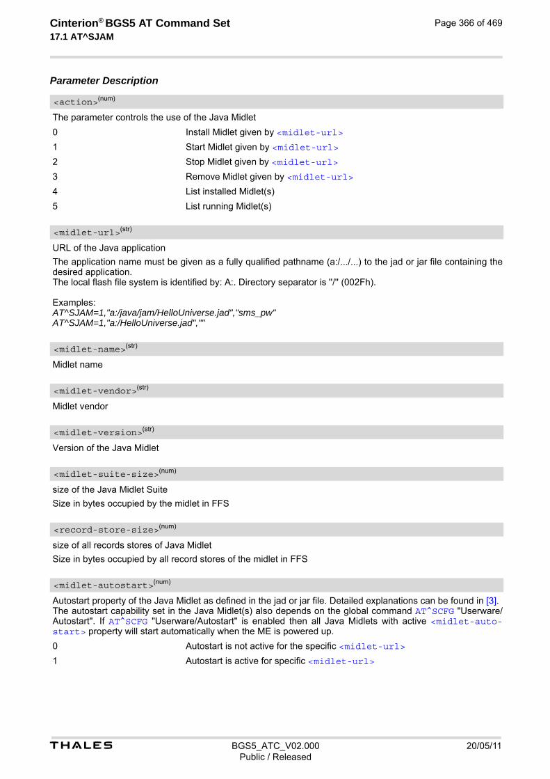
t BGS5_ATC_V02.000 20/05/11Public / Released
Cinterion® BGS5 AT Command Set 17.1 AT^SJAM
Page 366 of 469
Parameter Description
The parameter controls the use of the Java Midlet
0 Install Midlet given by <midlet-url>
1 Start Midlet given by <midlet-url>
2 Stop Midlet given by <midlet-url>
3 Remove Midlet given by <midlet-url>
4 List installed Midlet(s)
5 List running Midlet(s)
URL of the Java application
The application name must be given as a fully qualified pathname (a:/.../...) to the jad or jar file containing the desired application. The local flash file system is identified by: A:. Directory separator is ''/'' (002Fh). Examples: AT^SJAM=1,"a:/java/jam/HelloUniverse.jad","sms_pw" AT^SJAM=1,"a:/HelloUniverse.jad",""
Midlet name
Midlet vendor
Version of the Java Midlet
size of the Java Midlet Suite
Size in bytes occupied by the midlet in FFS
size of all records stores of Java Midlet
Size in bytes occupied by all record stores of the midlet in FFS
Autostart property of the Java Midlet as defined in the jad or jar file. Detailed explanations can be found in [3]. The autostart capability set in the Java Midlet(s) also depends on the global command AT^SCFG "Userware/Autostart". If AT^SCFG "Userware/Autostart" is enabled then all Java Midlets with active <midlet-auto-start> property will start automatically when the ME is powered up.
0 Autostart is not active for the specific <midlet-url>
1 Autostart is active for specific <midlet-url>
<action>(num)
<midlet-url>(str)
<midlet-name>(str)
<midlet-vendor>(str)
<midlet-version>(str)
<midlet-suite-size>(num)
<record-store-size>(num)
<midlet-autostart>(num)

t BGS5_ATC_V02.000 20/05/11Public / Released
Cinterion® BGS5 AT Command Set 17.1 AT^SJAM
Page 367 of 469
Notes• The parameters <midlet-url> and <upwd> are mandatory, if the status of a Java Midlet is changed (install,
start, stop, remove). See aso AT^SCFG "Userware/Passwd", <upwd>, for details on how to handle pass-words.
• Only one instance of each Java Midlet can run at the same time.
• The string parameters are in IRA format
• The autostart property status informs if the autostart property exists in the .jad file of the midlet. In that case the midlet can be autostarted ( see <ua>).
• As signatures are defined in jad files it is recommended to use only jad files for installing signed Java appli-cations. When installing jar files keep in mind that the installed application would be unsigned.
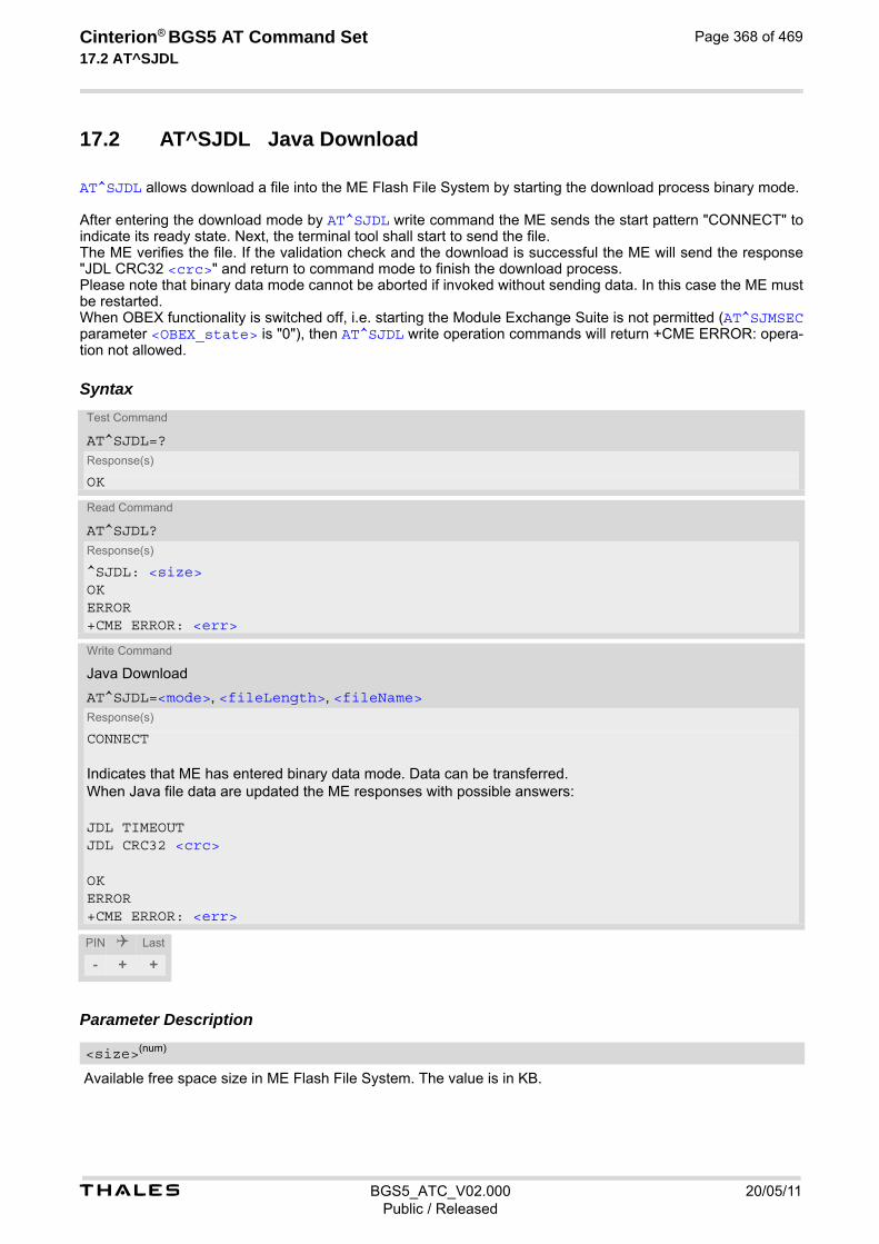
t BGS5_ATC_V02.000 20/05/11Public / Released
Cinterion® BGS5 AT Command Set 17.2 AT^SJDL
Page 368 of 469
17.2 AT^SJDL Java Download
AT^SJDL allows download a file into the ME Flash File System by starting the download process binary mode. After entering the download mode by AT^SJDL write command the ME sends the start pattern "CONNECT" to indicate its ready state. Next, the terminal tool shall start to send the file. The ME verifies the file. If the validation check and the download is successful the ME will send the response "JDL CRC32 <crc>" and return to command mode to finish the download process. Please note that binary data mode cannot be aborted if invoked without sending data. In this case the ME must be restarted. When OBEX functionality is switched off, i.e. starting the Module Exchange Suite is not permitted (AT^SJMSEC parameter <OBEX_state> is "0"), then AT^SJDL write operation commands will return +CME ERROR: opera-tion not allowed.
Syntax
Parameter Description
Available free space size in ME Flash File System. The value is in KB.
Test Command
AT^SJDL=?Response(s)
OK
Read Command
AT^SJDL?Response(s)
^SJDL: <size>OKERROR+CME ERROR: <err>
Write Command
Java Download
AT^SJDL=<mode>, <fileLength>, <fileName>Response(s)
CONNECT
Indicates that ME has entered binary data mode. Data can be transferred.When Java file data are updated the ME responses with possible answers:
JDL TIMEOUTJDL CRC32 <crc>
OKERROR+CME ERROR: <err>
PIN Last
- + +
<size>(num)
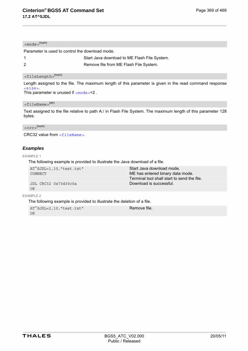
t BGS5_ATC_V02.000 20/05/11Public / Released
Cinterion® BGS5 AT Command Set 17.2 AT^SJDL
Page 369 of 469
Parameter is used to control the download mode.
1 Start Java download to ME Flash File System.
2 Remove file from ME Flash File System.
Length assigned to the file. The maximum length of this parameter is given in the read command response <size>. This parameter is unused if <mode>=2 .
Text assigned to the file relative to path A:/ in Flash File System. The maximum length of this parameter 128 bytes.
CRC32 value from <fileName>.
Examples EXAMPLE 1
The following example is provided to illustrate the Java download of a file.
EXAMPLE 2
The following example is provided to illustrate the deletion of a file.
<mode>(num)
<fileLength>(num)
<fileName>(str)
<crc>(num)
AT^SJDL=1,10,"test.txt" Start Java download mode.CONNECT ME has entered binary data mode.
Terminal tool shall start to send the file.JDL CRC32 0x73d30c0a Download is successful.OK
AT^SJDL=2,10,"test.txt" Remove file.OK
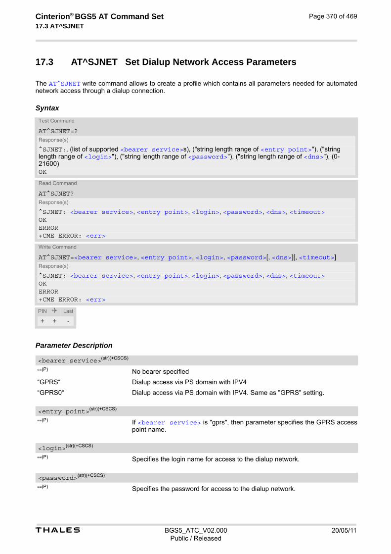
t BGS5_ATC_V02.000 20/05/11Public / Released
Cinterion® BGS5 AT Command Set 17.3 AT^SJNET
Page 370 of 469
17.3 AT^SJNET Set Dialup Network Access Parameters
The AT^SJNET write command allows to create a profile which contains all parameters needed for automated network access through a dialup connection.
Syntax
Parameter Description
““(P) No bearer specified
“GPRS“ Dialup access via PS domain with IPV4
“GPRS0“ Dialup access via PS domain with IPV4. Same as "GPRS" setting.
““(P) If <bearer service> is "gprs", then parameter specifies the GPRS access point name.
““(P) Specifies the login name for access to the dialup network.
““(P) Specifies the password for access to the dialup network.
Test Command
AT^SJNET=?Response(s)
^SJNET:, (list of supported <bearer service>s), ("string length range of <entry point>"), ("string length range of <login>"), ("string length range of <password>"), ("string length range of <dns>"), (0-21600)OK
Read Command
AT^SJNET?Response(s)
^SJNET: <bearer service>, <entry point>, <login>, <password>, <dns>, <timeout>OKERROR+CME ERROR: <err>
Write Command
AT^SJNET=<bearer service>, <entry point>, <login>, <password>[, <dns>][, <timeout>]Response(s)
^SJNET: <bearer service>, <entry point>, <login>, <password>, <dns>, <timeout>OKERROR+CME ERROR: <err>
PIN Last
+ + -
<bearer service>(str)(+CSCS)
<entry point>(str)(+CSCS)
<login>(str)(+CSCS)
<password>(str)(+CSCS)
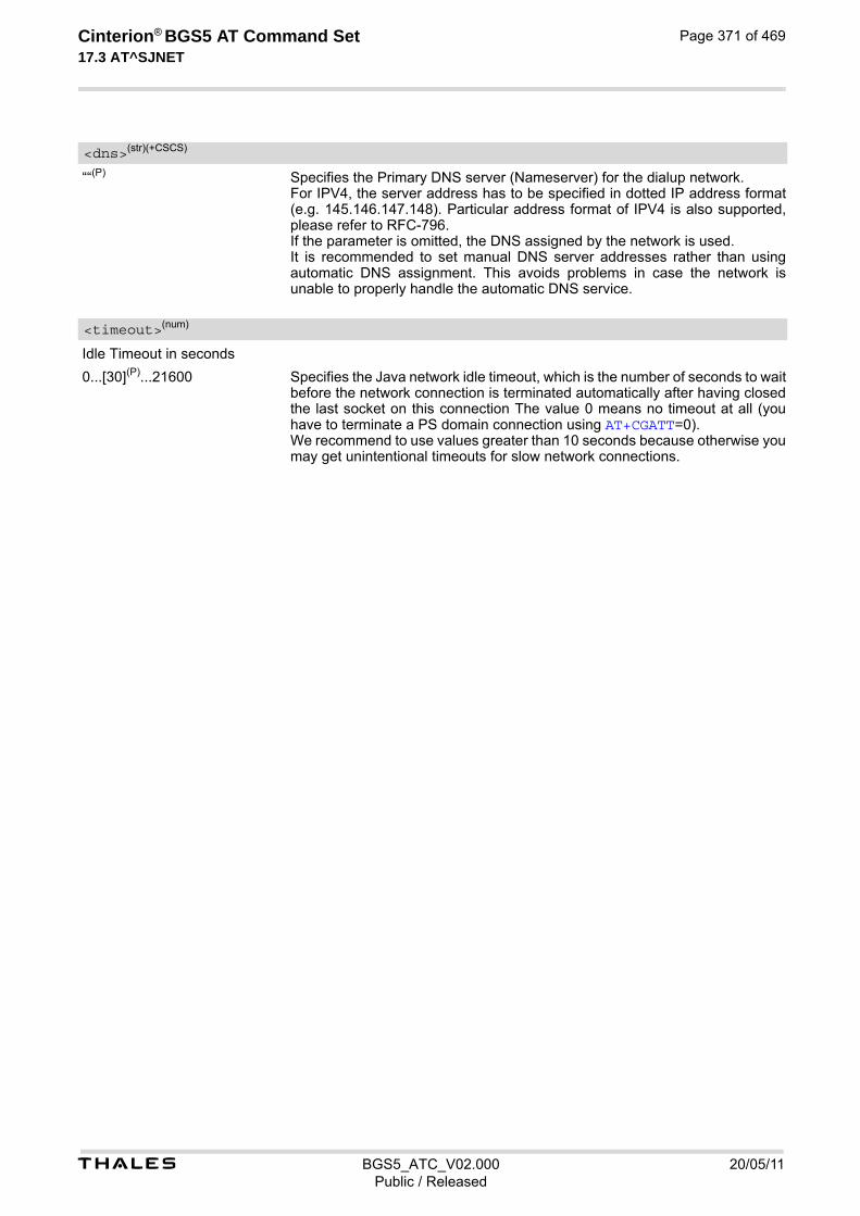
t BGS5_ATC_V02.000 20/05/11Public / Released
Cinterion® BGS5 AT Command Set 17.3 AT^SJNET
Page 371 of 469
““(P) Specifies the Primary DNS server (Nameserver) for the dialup network. For IPV4, the server address has to be specified in dotted IP address format (e.g. 145.146.147.148). Particular address format of IPV4 is also supported, please refer to RFC-796. If the parameter is omitted, the DNS assigned by the network is used. It is recommended to set manual DNS server addresses rather than using automatic DNS assignment. This avoids problems in case the network is unable to properly handle the automatic DNS service.
Idle Timeout in seconds
0...[30](P)...21600 Specifies the Java network idle timeout, which is the number of seconds to wait before the network connection is terminated automatically after having closed the last socket on this connection The value 0 means no timeout at all (you have to terminate a PS domain connection using AT+CGATT=0). We recommend to use values greater than 10 seconds because otherwise you may get unintentional timeouts for slow network connections.
<dns>(str)(+CSCS)
<timeout>(num)

t BGS5_ATC_V02.000 20/05/11Public / Released
Cinterion® BGS5 AT Command Set 17.4 AT^SJOTAP
Page 372 of 469
17.4 AT^SJOTAP Over The Air Application Provisioning
The AT^SJOTAP command serves to control and start OTAP operations for installing and updating Java appli-cations over the air. Detailed explanations can be found in [3]. The AT^SJOTAP write command sets the password and all parameters required to install / delete a Java Appli-cation. The AT^SJOTAP execute command starts the OTAP install process. Parameters that are set by AT command cannot be overwritten by SMS. Parameters that were not configured by AT command can be configured via SMS - however, the SMS configuration will not be saved. For security reasons these parameters should therefore also be configured by AT command before the first OTAP is triggered by SMS. The URL parameter <Jad_URL> set by SMS will be appended to the end of the <Jad_URL> set by this command. This can be used to handle different Java applications on the same server. After a firmware update, it is recommended to configure the OTAP parameters by AT command again, because the previously saved configuration (with the previous firmware) may be out-of-date.
Syntax
Test Command
AT^SJOTAP=?Response(s)
^SJOTAP:(max. string length of <SMS_pwd>), (max. string length of <Jad_URL>), (max. string length of <Appl_Dir>), (max. string length of <HTTP_User>), (max. string length of <HTTP_Pwd>), (list of supported <BS>), (max. string length of <Dest>), (max. string length of <Net_user>), (max. string length of <Net_pwd>), (max. string length of <DNS>), (max. string length of <NotifyURL>), (list of supported <Ignore_Sms_PID>), (list of supported <Hide_HTTP_auth_params>), (max. string length of <upwd2>)OK
Read Command
AT^SJOTAP?Response(s)
^SJOTAP: <SMS_pwd>, <Jad_URL>, <Appl_Dir>, <HTTP_User>, <HTTP_Pwd>, <BS>, <Dest>, <Net_user>, <Net_pwd>, <DNS>, <NotifyURL>, <Ignore_Sms_PID>, <Hide_HTTP_auth_params>OKERROR+CME ERROR: <err>
Exec Command
AT^SJOTAPResponse(s)
OKERROR+CME ERROR: <err>
Write Command
AT^SJOTAP=[<SMS_pwd>][, <Jad_URL>][, <Appl_Dir>][, <HTTP_User>][, <HTTP_Pwd>][, <BS>][, <Dest>][, <Net_user>][, <Net_pwd>][, <DNS>][, <NotifyURL>][, <Ignore_Sms_PID>][, <Hide_HTTP_auth_params>][, <upwd2>]Response(s)
OKERROR+CME ERROR: <err>
PIN Last
+ - -

t BGS5_ATC_V02.000 20/05/11Public / Released
Cinterion® BGS5 AT Command Set 17.4 AT^SJOTAP
Page 373 of 469
Parameter Description
Password for OTAP SMS authentification
URL of update file
Directory of Java application
Parameter is not supported
HTTP user name
HTTP password
Bearer Service
“GPRS“ Use PS domain bearer with IPV4.
“GPRS0“ Use PS domain bearer with IPV4. Same as "GPRS" for IPv4.
Destination
Access point name (APN)
User name for accessing the network
Password for accessing the network
Domain Name Server
URL to which result codes are posted
Ignore SMS PID
“on“ Set ignore SMS PID "on".
[“off“] Set ignore SMS PID "off".
<SMS_pwd>(str)
<Jad_URL>(str)
<Appl_Dir>(str)
<HTTP_User>(str)
<HTTP_Pwd>(str)
<BS>(str)
<Dest>(str)
<Net_user>(str)
<Net_pwd>(str)
<DNS>(str)
<NotifyURL>(str)
<Ignore_Sms_PID>(str)

t BGS5_ATC_V02.000 20/05/11Public / Released
Cinterion® BGS5 AT Command Set 17.4 AT^SJOTAP
Page 374 of 469
Hide HTTP authentication parameters
“on“ Set hide HTTP authentication parameters "on".
[“off“] Set hide HTTP authentication parameters "off". Notes• The authentication mode for GPRS is always PAP.
• All parameters (except <Ignore_Sms_PID> and <Hide_HTTP_auth_params>) which are left out in the write command are set to "not configured", while parameters which are entered as "" will be stored as an empty string.
• Parameters <Ignore_Sms_PID> and <Hide_HTTP_auth_params> which are entered as "" will be stored as "off".
• Parameters that are set by AT command cannot be reconfigured / overwritten by SMS. The URL parameter <Jad_URL> set by SMS will be appended to the end of the <Jad_URL> set by this command. This can be used to handle different Java applications on the same server. Parameters that were not configured by AT command can be configured via SMS - however, the SMS con-figuration will not be saved. For security reasons these parameters should therefore be configured by AT command before the first OTAP is triggered by SMS. After a firmware update, it is recommended to configure the OTAP parameters by AT command again, because the previously saved configuration (with the previous firmware) may be out-of-date.
• If the execute command ends up with an error, one or more mandatory parameters have not been specified (see [3]). For the installation of Java applications via OTAP, the parameters <BS> and <Dest> are mandatory. For the deletion of Java applications via OTAP, if the parameter <NotifyURL> is specified, the parameters <BS> and <Dest> are also mandatory.
• The string parameters are in IRA format.
• If set, <upwd2> usage mandatory for local AT^SJOTAP calls.
<Hide_HTTP_auth_params>(str)

t BGS5_ATC_V02.000 20/05/11Public / Released
Cinterion® BGS5 AT Command Set 17.5 AT^SJMSEC
Page 375 of 469
17.5 AT^SJMSEC Java Midlet Security
AT^SJMSEC configures the Java Midlet security. A detailed description of how to create the binary files and con-figure the Java security environment can be found in [3]. AT^SJMSEC can be operated in two modes. Direct command mode: The subsequent <CmdData> parameter contains the Java security commands, such as:
• Del Customer Keystore
• Switch on/off Certificate Verification for HTTPS Connections
• Switch on/off OBEX Functionality
• Del Certificate
• Del all Certificates
• Del Https Client Certificate
Indirect command mode: Java security commands are contained in files stored in the FFS, such as the following:
• Set Customer Keystore
• Add Certificate
• Add HTTPS Client Certificate
IMPORTANT: After each Java security command the ME must be reset.
Syntax
Test Command
AT^SJMSEC=?Response(s)
^SJMSEC:(list of supported <CmdMode>s), (max. string length of <CmdData>)OK
Read Command
AT^SJMSEC?Response(s)
^SJMSEC: <keystore_state>, <HTTPS_state>, <OBEX_state>, <HTTPS_cl_cert>OKERROR+CME ERROR: <err>
Write Command
AT^SJMSEC=<CmdMode>, <CmdData>Response(s)
OKIf not successful:^SJMSEC:<error_code>, <str>ERROR+CME ERROR: <err>
PIN Last
- + +
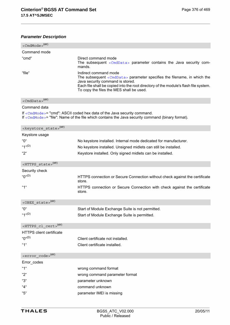
t BGS5_ATC_V02.000 20/05/11Public / Released
Cinterion® BGS5 AT Command Set 17.5 AT^SJMSEC
Page 376 of 469
Parameter Description
Command mode
“cmd“ Direct command mode The subsequent <CmdData> parameter contains the Java security com-mands.
“file“ Indirect command mode The subsequent <CmdData> parameter specifies the filename, in which the Java security command is stored. Each file shall be copied into the root directory of the module's flash file system. To copy the files the MES shall be used.
Command data
If <CmdMode>= "cmd": ASCII coded hex data of the Java security command. If <CmdMode>= "file": Name of the file which contains the Java security command (binary format).
Keystore usage
“0“ No keystore installed. Internal mode dedicated for manufacturer.
“1“(D) No keystore installed. Unsigned midlets can still be installed.
“2“ Keystore installed. Only signed midlets can be installed.
Security check
“0“(D) HTTPS connection or Secure Connection without check against the certificate store.
“1“ HTTPS connection or Secure Connection with check against the certificate store.
“0“ Start of Module Exchange Suite is not permitted.
“1“(D) Start of Module Exchange Suite is permitted.
HTTPS client certificate
“0“(D) Client certificate not installed.
“1“ Client certificate installed.
Error_codes
“1“ wrong command format
“2“ wrong command parameter format
“3“ parameter unknown
“4“ command unknown
“5“ parameter IMEI is missing
<CmdMode>(str)
<CmdData>(str)
<keystore_state>(str)
<HTTPS_state>(str)
<OBEX_state>(str)
<HTTPS_cl_cert>(str)
<error_code>(str)
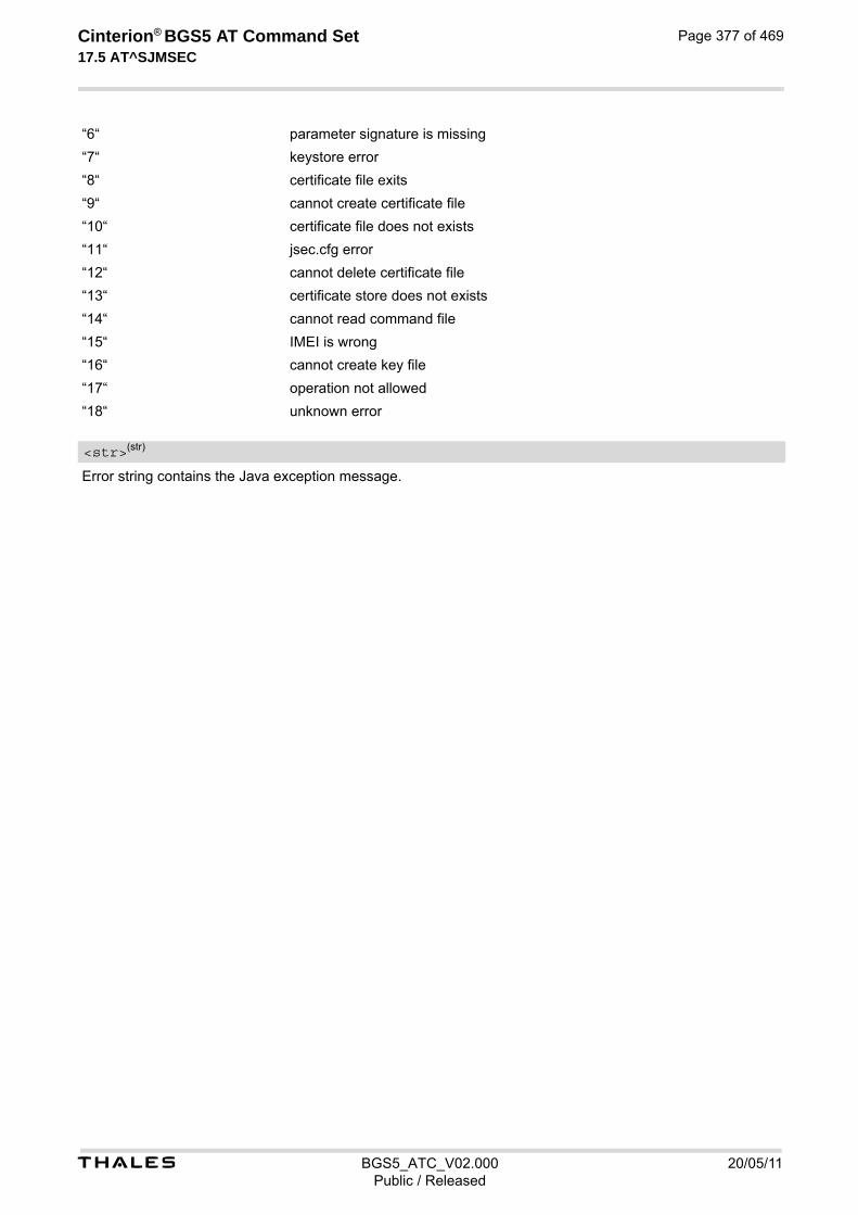
t BGS5_ATC_V02.000 20/05/11Public / Released
Cinterion® BGS5 AT Command Set 17.5 AT^SJMSEC
Page 377 of 469
“6“ parameter signature is missing
“7“ keystore error
“8“ certificate file exits
“9“ cannot create certificate file
“10“ certificate file does not exists
“11“ jsec.cfg error
“12“ cannot delete certificate file
“13“ certificate store does not exists
“14“ cannot read command file
“15“ IMEI is wrong
“16“ cannot create key file
“17“ operation not allowed
“18“ unknown error
Error string contains the Java exception message.
<str>(str)
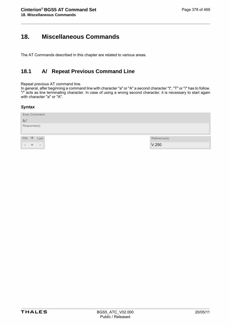
Cinterion® BGS5 AT Command Set 18. Miscellaneous Commands
t BGS5_ATC_V02.000 20/05/11Public / Released
Page 378 of 469
18. Miscellaneous Commands
The AT Commands described in this chapter are related to various areas.
18.1 A/ Repeat Previous Command Line
Repeat previous AT command line. In general, after beginning a command line with character "a" or "A" a second character "t", "T" or "/" has to follow. "/" acts as line terminating character. In case of using a wrong second character, it is necessary to start again with character "a" or "A".
SyntaxExec Command
A/Response(s)
PIN Last Reference(s)
- + - V.250

t BGS5_ATC_V02.000 20/05/11Public / Released
Cinterion® BGS5 AT Command Set 18.2 ATS3
Page 379 of 469
18.2 ATS3 Command Line Termination
ATS3 is implemented for compatibility reasons only, and has no effect.
Syntax
Parameter Description
000...013(&F)...127 Notes• Command ATS3 is dummy, and has no effect on module behavior.
• Read command will return value written by user or default value n=13.
• Write command will return OK or ERROR. OK - when parameter <n> is in range, ERROR otherwise.
• Despite OK returned in case of any parameter from range, no changes will be made.
• Parameter is volatile.
• If changing this setting the new value has no effect for "^SHUTDOWN" URC.
Read Command
ATS3?Response(s)
<n>OK
Write Command
ATS3=<n>Response(s)
OKERROR
PIN Last Reference(s)
- + - ITU-T V.250 [15]
<n>(num)(&V)(&W)

t BGS5_ATC_V02.000 20/05/11Public / Released
Cinterion® BGS5 AT Command Set 18.3 ATS4
Page 380 of 469
18.3 ATS4 Response Formatting
ATS4 is implemented for compatibility reasons only, and has no effect.
Syntax
Parameter Description
000...010(&F)...127 Notes• Command ATS4 is dummy, and has no effect on module behavior.
• Read command will return value written by user or default value n=10.
• Write command will return OK or ERROR. OK - when parameter <n> is in range, ERROR otherwise.
• Despite OK returned in case of any parameter from range, no changes will be made.
• Parameter is volatile.
Read Command
ATS4?Response(s)
<n>OK
Write Command
ATS4=<n>Response(s)
OKERROR
PIN Last Reference(s)
- + - ITU-T V.250 [15]
<n>(num)(&V)(&W)

t BGS5_ATC_V02.000 20/05/11Public / Released
Cinterion® BGS5 AT Command Set 18.4 ATS5
Page 381 of 469
18.4 ATS5 Command Line Editing
ATS5 is implemented for compatibility reasons only, and has no effect.
Syntax
Parameter Description
000...008(&F)...127 Notes• Command ATS5 is dummy, and has no effect on module behavior.
• Read command will return value written by user or default value n=8.
• Write command will return OK or ERROR. OK - when parameter <n> is in range, ERROR otherwise.
• Despite OK returned in case of any parameter from range, no changes will be made.
• Parameter is volatile.
Read Command
ATS5?Response(s)
<n>OK
Write Command
ATS5=<n>Response(s)
OKERROR
PIN Last Reference(s)
- + - ITU-T V.250 [15]
<n>(num)(&V)(&W)
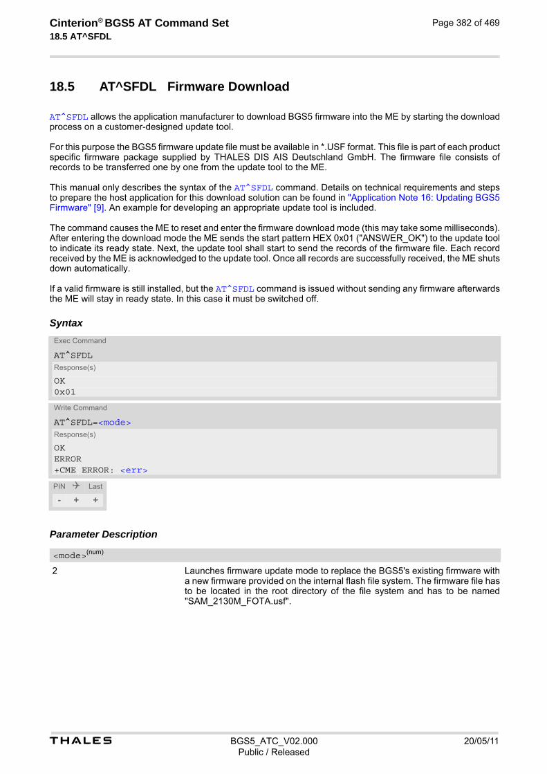
t BGS5_ATC_V02.000 20/05/11Public / Released
Cinterion® BGS5 AT Command Set 18.5 AT^SFDL
Page 382 of 469
18.5 AT^SFDL Firmware Download
AT^SFDL allows the application manufacturer to download BGS5 firmware into the ME by starting the download process on a customer-designed update tool. For this purpose the BGS5 firmware update file must be available in *.USF format. This file is part of each product specific firmware package supplied by THALES DIS AIS Deutschland GmbH. The firmware file consists of records to be transferred one by one from the update tool to the ME. This manual only describes the syntax of the AT^SFDL command. Details on technical requirements and steps to prepare the host application for this download solution can be found in "Application Note 16: Updating BGS5 Firmware" [9]. An example for developing an appropriate update tool is included. The command causes the ME to reset and enter the firmware download mode (this may take some milliseconds). After entering the download mode the ME sends the start pattern HEX 0x01 ("ANSWER_OK") to the update tool to indicate its ready state. Next, the update tool shall start to send the records of the firmware file. Each record received by the ME is acknowledged to the update tool. Once all records are successfully received, the ME shuts down automatically. If a valid firmware is still installed, but the AT^SFDL command is issued without sending any firmware afterwards the ME will stay in ready state. In this case it must be switched off.
Syntax
Parameter Description
2 Launches firmware update mode to replace the BGS5's existing firmware with a new firmware provided on the internal flash file system. The firmware file has to be located in the root directory of the file system and has to be named "SAM_2130M_FOTA.usf".
Exec Command
AT^SFDLResponse(s)
OK0x01
Write Command
AT^SFDL=<mode>Response(s)
OKERROR+CME ERROR: <err>
PIN Last
- + +
<mode>(num)
t BGS5_ATC_V02.000 20/05/11Public / Released
Cinterion® BGS5 AT Command Set 18.6 AT^SFSA
Page 383 of 469
18.6 AT^SFSA Flash File System Access
AT^SFSA provides access to the Flash File System. The following functionality is supported:
• Reading global status information, available storage and max. storage size
• Creating and deleting files and directories
• Reading file status information, e.g. file size, optional date
• Renaming files and directories
• Copying files
• Listing directory contents
• Computation and displaying CRC of a given file
• Reading and writing an arbitrary amount of data per call (max. 1500 bytes per single call)
• Providing random access to the file data and a seek function
Flash File System Requirements: AT^SFSA="gstat" shows the maximum memory space of the FFS (see <StorageSize>) and the free memory space (see <FreeSpace>). As the file system is block structured the <FreeSpace> value will decrease only in full block multiples. The block size is 2048 bytes. Keep in mind that the entire memory space comprises both user data and internal resources for the file system infrastructure. As a result, the free memory space depends on the file size, the number of files and the number of created directories. In short, the more files / folders you create, and the more internal data is used from the system, the less memory will be available for user data. If the limit is reached, the error code ^SFSA: 28 will be returned. Please consider the following rules for an efficient FFS management:
• The maximum number of directories altogether in the root directory and all subdirectories is limited to 100. The maximum number of files is about 1000 altogether in the root directory and all subdirectories. Note: It is not possible to use these maximum numbers of file system entries, the actual amount of files and directories may be lower, because some of them are used internally by the Java system in the Java applica-tion manager, e.g. for installed MIDlets. Note: Ensure not to fill up the file system to its limits, otherwise the Java system may run into trouble.
• The subdirectory depth shall not be greater than 5.
• Allowed characters for path and file names:
- Path and file names are alphanumeric. Allowed characters: A - Z, a - z, digits, underscore, and special characters used in file URL format defined in IETF RFCs 1738 and 2396. Space characters are allowed as well, but require the whole path or file name be enclosed in quotation marks (e.g. "a:/dire ctory/my file.txt" or "a:/ directory/my file.txt"), otherwise the spaces will be discarded.
- Character "/" is a separator for directories and files, e.g. /directory/my_sub_dir/my_file.txt.
- Both "." and ".." are illegal for directory names, "." as part of a file name is allowed.
- File and directory names are case-insensitive..
- Path names start with drive prefix "a:/" or "A:/".
• Length of files and paths (incl. drive prefix "a:/" or "A:/"): The maximum usable length is 127 GSM characters and accordingly 31 UCS2 characters (depending on character set selected with AT+CSCS).
• If the file is in open status, it must be closed first before executing other file operations such as copy, rename and remove.
• When OBEX functionality is switched off, i.e. starting the Module Exchange Suite is not permitted ( AT^SJM-SEC parameter <OBEX_state> is "0"), then AT^SFSA file operation commands will return +CME ERROR: operation not allowed.

t BGS5_ATC_V02.000 20/05/11Public / Released
Cinterion® BGS5 AT Command Set 18.6 AT^SFSA
Page 384 of 469
SyntaxTest Command
AT^SFSA=?Response(s)
^SFSA: "close", (range of <fh>)^SFSA: "copy", (max. string length of <path>), (max. string length of <DestinationPath>), (list of supported <CopyFlag>s)^SFSA: "crc", (max. string length of <path>)^SFSA: "gstat", (list of supported <drive>s)^SFSA: "ls", (max. string length of <path>), (list of supported <ListFlag>)^SFSA: "mkdir", (max. string length of <path>)^SFSA: "open", (max. string length of <path>), (range of <flag>)^SFSA: "read", (range of <fh>), (max. value of <size>)^SFSA: "remove", (max. string length of <path>)^SFSA: "rename", (max. string length of <path>), (max. string length of <name>)^SFSA: "rmdir", (max. string length of <path>)^SFSA: "seek", (range of <fh>), (range of <offset>), (list of supported <SeekFlag>)^SFSA: "stat", (max. string length of <path>)^SFSA: "write", (range of <fh>), (max. value of <size>)OK
Write Command
Close a file. The file has to be successfully opened before.
AT^SFSA="close", <fh>Response(s)
In case of success:^SFSA: <result>OKIn case of error:^SFSA: <result>ERROR+CME ERROR: <err>
Write Command
Copy a file given by the <path> parameter to the file given by the<DestinationPath>. Both names should not be identical, otherwise copy operation returns error "path already exists".
AT^SFSA="copy", <path>, <DestinationPath>[, <CopyFlag>]Response(s)
In case of success:^SFSA: <result>OKIn case of error:^SFSA: <result>ERROR+CME ERROR: <err>
Write Command
Compute CRC of a file.
AT^SFSA="crc", <path>Response(s)
In case of success:^SFSA: <crc>, <result>OKIn case of error:^SFSA: <result>
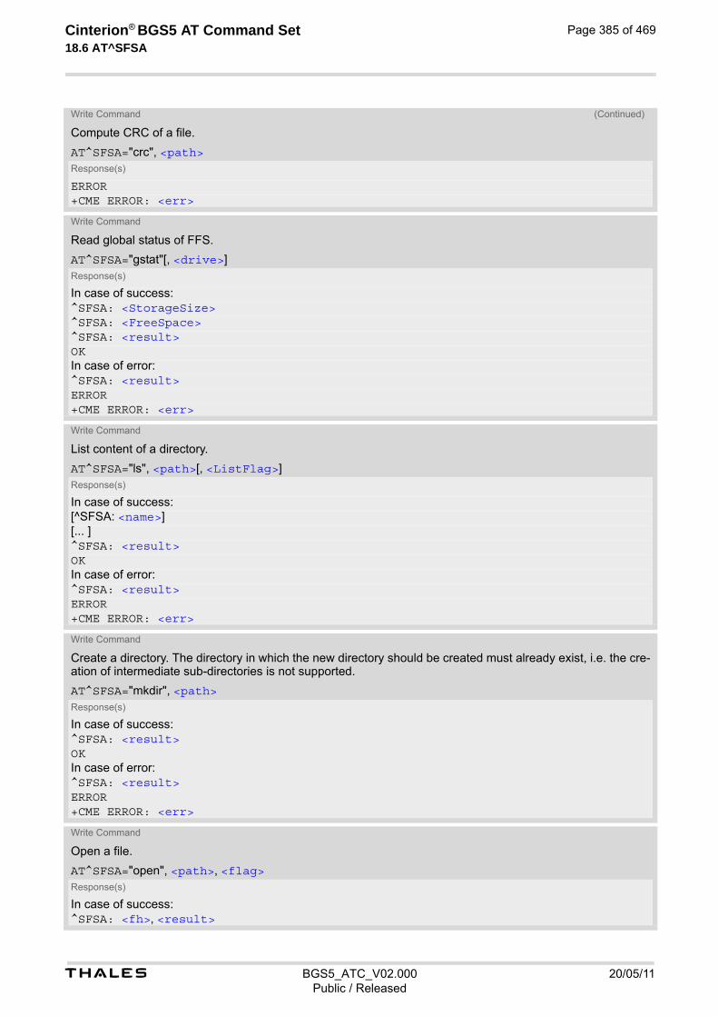
t BGS5_ATC_V02.000 20/05/11Public / Released
Cinterion® BGS5 AT Command Set 18.6 AT^SFSA
Page 385 of 469
ERROR+CME ERROR: <err>
Write Command
Read global status of FFS.
AT^SFSA="gstat"[, <drive>]Response(s)
In case of success:^SFSA: <StorageSize>^SFSA: <FreeSpace>^SFSA: <result>OKIn case of error:^SFSA: <result>ERROR+CME ERROR: <err>
Write Command
List content of a directory.
AT^SFSA="ls", <path>[, <ListFlag>]Response(s)
In case of success:[^SFSA: <name>][... ]^SFSA: <result>OKIn case of error:^SFSA: <result>ERROR+CME ERROR: <err>
Write Command
Create a directory. The directory in which the new directory should be created must already exist, i.e. the cre-ation of intermediate sub-directories is not supported.
AT^SFSA="mkdir", <path>Response(s)
In case of success:^SFSA: <result>OKIn case of error:^SFSA: <result>ERROR+CME ERROR: <err>
Write Command
Open a file.
AT^SFSA="open", <path>, <flag>Response(s)
In case of success:^SFSA: <fh>, <result>
Write Command (Continued)
Compute CRC of a file.
AT^SFSA="crc", <path>Response(s)
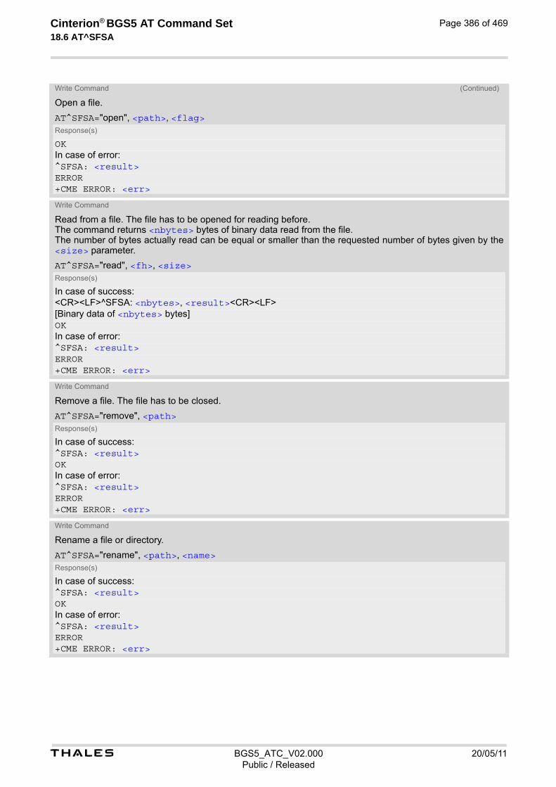
t BGS5_ATC_V02.000 20/05/11Public / Released
Cinterion® BGS5 AT Command Set 18.6 AT^SFSA
Page 386 of 469
OKIn case of error:^SFSA: <result>ERROR+CME ERROR: <err>
Write Command
Read from a file. The file has to be opened for reading before. The command returns <nbytes> bytes of binary data read from the file. The number of bytes actually read can be equal or smaller than the requested number of bytes given by the <size> parameter.
AT^SFSA="read", <fh>, <size>Response(s)
In case of success:<CR><LF>^SFSA: <nbytes>, <result><CR><LF>[Binary data of <nbytes> bytes]OKIn case of error:^SFSA: <result>ERROR+CME ERROR: <err>
Write Command
Remove a file. The file has to be closed.
AT^SFSA="remove", <path>Response(s)
In case of success:^SFSA: <result>OKIn case of error:^SFSA: <result>ERROR+CME ERROR: <err>
Write Command
Rename a file or directory.
AT^SFSA="rename", <path>, <name>Response(s)
In case of success:^SFSA: <result>OKIn case of error:^SFSA: <result>ERROR+CME ERROR: <err>
Write Command (Continued)
Open a file.
AT^SFSA="open", <path>, <flag>Response(s)
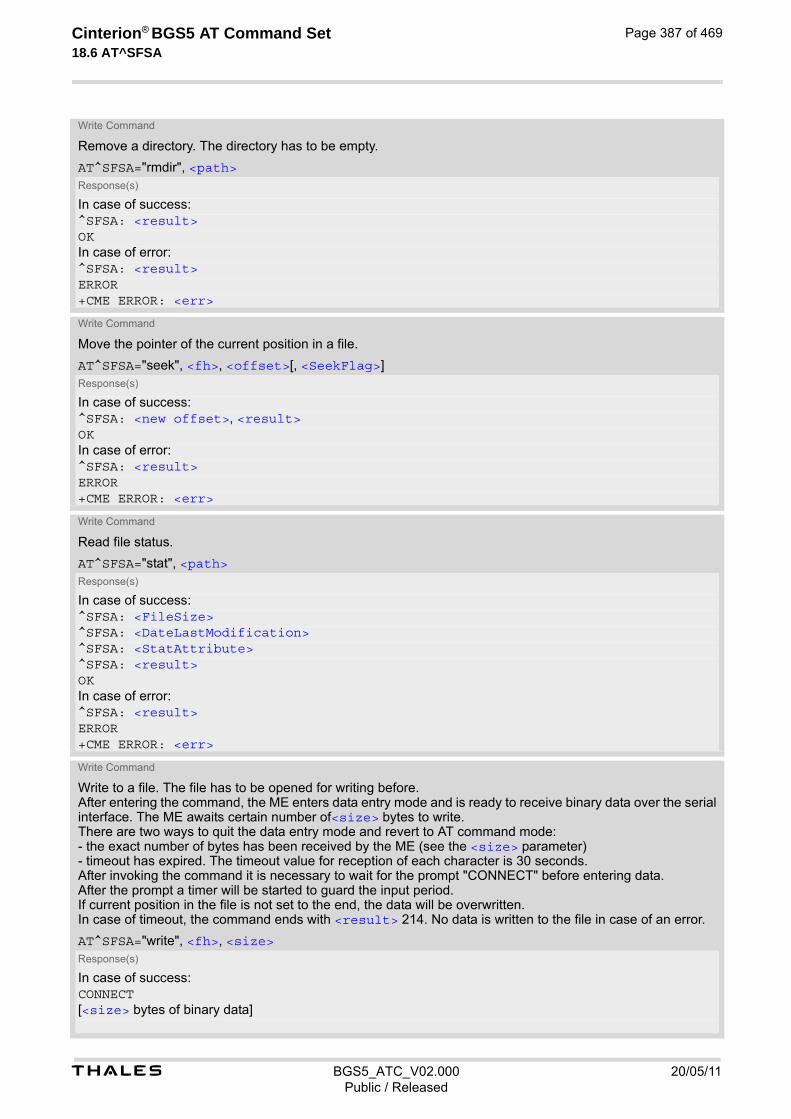
t BGS5_ATC_V02.000 20/05/11Public / Released
Cinterion® BGS5 AT Command Set 18.6 AT^SFSA
Page 387 of 469
Write Command
Remove a directory. The directory has to be empty.
AT^SFSA="rmdir", <path>Response(s)
In case of success:^SFSA: <result>OKIn case of error:^SFSA: <result>ERROR+CME ERROR: <err>
Write Command
Move the pointer of the current position in a file.
AT^SFSA="seek", <fh>, <offset>[, <SeekFlag>]Response(s)
In case of success:^SFSA: <new offset>, <result>OKIn case of error:^SFSA: <result>ERROR+CME ERROR: <err>
Write Command
Read file status.
AT^SFSA="stat", <path>Response(s)
In case of success:^SFSA: <FileSize>^SFSA: <DateLastModification>^SFSA: <StatAttribute>^SFSA: <result>OKIn case of error:^SFSA: <result>ERROR+CME ERROR: <err>
Write Command
Write to a file. The file has to be opened for writing before. After entering the command, the ME enters data entry mode and is ready to receive binary data over the serial interface. The ME awaits certain number of<size> bytes to write. There are two ways to quit the data entry mode and revert to AT command mode: - the exact number of bytes has been received by the ME (see the <size> parameter) - timeout has expired. The timeout value for reception of each character is 30 seconds. After invoking the command it is necessary to wait for the prompt "CONNECT" before entering data. After the prompt a timer will be started to guard the input period. If current position in the file is not set to the end, the data will be overwritten. In case of timeout, the command ends with <result> 214. No data is written to the file in case of an error.
AT^SFSA="write", <fh>, <size>Response(s)
In case of success:CONNECT[<size> bytes of binary data]
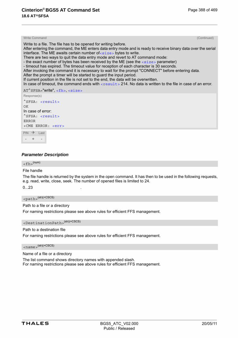
t BGS5_ATC_V02.000 20/05/11Public / Released
Cinterion® BGS5 AT Command Set 18.6 AT^SFSA
Page 388 of 469
Parameter Description
File handle
The file handle is returned by the system in the open command. It has then to be used in the following requests, e.g. read, write, close, seek. The number of opened files is limited to 24.
0...23 .
Path to a file or a directory
For naming restrictions please see above rules for efficient FFS management.
Path to a destination file
For naming restrictions please see above rules for efficient FFS management.
Name of a file or a directory
The list command shows directory names with appended slash. For naming restrictions please see above rules for efficient FFS management.
^SFSA: <result>OKIn case of error:^SFSA: <result>ERROR+CME ERROR: <err>
PIN Last
- + -
<fh>(num)
<path>(str)(+CSCS)
<DestinationPath>(str)(+CSCS)
<name>(str)(+CSCS)
Write Command (Continued)
Write to a file. The file has to be opened for writing before. After entering the command, the ME enters data entry mode and is ready to receive binary data over the serial interface. The ME awaits certain number of<size> bytes to write. There are two ways to quit the data entry mode and revert to AT command mode: - the exact number of bytes has been received by the ME (see the <size> parameter) - timeout has expired. The timeout value for reception of each character is 30 seconds. After invoking the command it is necessary to wait for the prompt "CONNECT" before entering data. After the prompt a timer will be started to guard the input period. If current position in the file is not set to the end, the data will be overwritten. In case of timeout, the command ends with <result> 214. No data is written to the file in case of an error.
AT^SFSA="write", <fh>, <size>Response(s)

t BGS5_ATC_V02.000 20/05/11Public / Released
Cinterion® BGS5 AT Command Set 18.6 AT^SFSA
Page 389 of 469
File access flags
All available flags are divided into two groups: primary and optional. To select the desired flag combination, cal-culate the sum of the values and use the resulting value. Writing data to file can take up to 180 seconds due to internal flash file system data processing.
Primary group:
1 Write. When set it is still allowed to read out the file content. After applying it on the file with read-only or hidden attribute, the file attribute will not be changed.
2 Read/write. Has priority over the read-only, hidden and write flags, when set in combination with them. After applying it on the file with read-only or hidden attribute, the file attribute will be cleared.
32 Hidden.
64 Read-only.
Optional group:
4 Append. Set the current position in the file to the end of the file. If append flag is not used, current position will be set to the beginning of the file.
8 Create. Create the file if it does not exist. Otherwise the existing file will be opened.
16 Truncate. Truncate the file to the size 0. This truncate operation is not applica-ble on a file which has Read-only attribute and has priority over Append, Write and Read/Write when set in combination with them. The file will first be trun-cated to size 0, then other operation will take effect. Has effect only when used with the write or read/write flag. Otherwise the usage is erroneous. Depending on the file size, truncating may take a couple of seconds.
Seek flags
Determines how the new position is calculated.
[0] Offset from the beginning of the file. The new position in the file equals <off-set>. The offset has to be positive or zero.
1 Offset from the current file position. The new position in the file equals the cur-rent position + <offset>. The <offset> can be positive, zero or negative. In case the new position exceeds the allowed range for the <offset> parame-ter, the behavior of the seek operation is undefined.
2 Offset from the end of the file. The new position in the file equals the file size + <offset>. The offset has to be negative or zero.
Copy flags
Determines whether or not copy works as force copy behavior, when destination path entry already exists.
[0] Performs normal copy, reporting error when destination path entry already exists.
1 Performs force copy, replacing destination path entry which already exists. Even when using force copy, the two path <path> and <DestinationPath> should not be identical, otherwise copy operation will return error "path already exists"; If force copy failed during operation, the <DestinationPath>'s entry file will be removed without recovery.
<flag>(num)
<SeekFlag>(num)
<CopyFlag>(num)
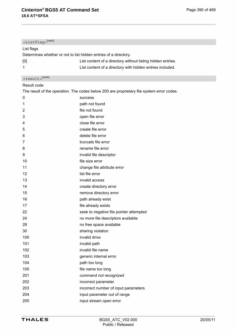
t BGS5_ATC_V02.000 20/05/11Public / Released
Cinterion® BGS5 AT Command Set 18.6 AT^SFSA
Page 390 of 469
List flags
Determines whether or not to list hidden entries of a directory.
[0] List content of a directory without listing hidden entries.
1 List content of a directory with hidden entries included.
Result code
The result of the operation. The codes below 200 are proprietary file system error codes.
0 success
1 path not found
2 file not found
3 open file error
4 close file error
5 create file error
6 delete file error
7 truncate file error
8 rename file error
9 invalid file descriptor
10 file size error
11 change file attribute error
12 list file error
13 invalid access
14 create directory error
15 remove directory error
16 path already exist
17 file already exists
22 seek to negative file pointer attempted
24 no more file descriptors available
28 no free space available
30 sharing violation
100 invalid drive
101 invalid path
102 invalid file name
103 generic internal error
104 path too long
105 file name too long
201 command not recognized
202 incorrect parameter
203 incorrect number of input parameters
204 input parameter out of range
205 input stream open error
<ListFlag>(num)
<result>(num)
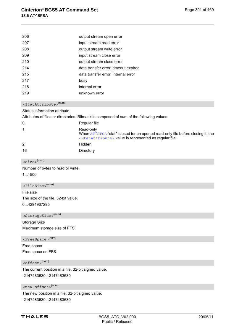
t BGS5_ATC_V02.000 20/05/11Public / Released
Cinterion® BGS5 AT Command Set 18.6 AT^SFSA
Page 391 of 469
206 output stream open error
207 input stream read error
208 output stream write error
209 input stream close error
210 output stream close error
214 data transfer error: timeout expired
215 data transfer error: internal error
217 busy
218 internal error
219 unknown error
Status information attribute
Attributes of files or directories. Bitmask is composed of sum of the following values:
0 Regular file
1 Read-only When AT^SFSA "stat" is used for an opened read-only file before closing it, the <StatAttribute> value is represented as regular file.
2 Hidden
16 Directory
Number of bytes to read or write.
1...1500
File size
The size of the file. 32-bit value.
0...4294967295
Storage Size
Maximum storage size of FFS.
Free space
Free space on FFS.
The current position in a file. 32-bit signed value.
-2147483630...2147483630
The new position in a file. 32-bit signed value.
-2147483630...2147483630
<StatAttribute>(num)
<size>(num)
<FileSize>(num)
<StorageSize>(num)
<FreeSpace>(num)
<offset>(num)
<new offset>(num)

t BGS5_ATC_V02.000 20/05/11Public / Released
Cinterion® BGS5 AT Command Set 18.6 AT^SFSA
Page 392 of 469
CRC check-sum computed on a file. 16-bit value. The check-sum is calculated using the initial value 65535 (hex 0xFFFF). The polynomial generator is x16 + x12
+ x5 + 1 and the final XOR value equals 65535 (hex 0xFFFF). The low-bit order is used for the whole calculation (the least-significant bit at the leftmost position in a byte).
0...65535
Number of bytes
The number of bytes read.
1...1500
Default "A:/".
Date of last file modification
If the file size is not changed during modification, the timestamp will not be updated. Format is "yy/mm/dd,hh:mm:ss", where the characters indicate the two last digits of the year, followed by month, day, hour, minutes, seconds; for example 6th of July 2005, 22:10:00 hours equals to "05/07/06,22:10:00"
<crc>(num)
<nbytes>(num)
<drive>(str)(+CSCS)
<DateLastModification>(str)

t BGS5_ATC_V02.000 20/05/11Public / Released
Cinterion® BGS5 AT Command Set 18.7 AT^SRVCFG
Page 393 of 469
18.7 AT^SRVCFG Service Configuration Settings
The AT^SRVCFG can be used to query and configure various settings of extra services supported by the BGS5. The AT^SRVCFG write command queries a configuration parameter (if no value is input) or sets its value(s).
SyntaxTest Command
AT^SRVCFG=?Response(s)
^SRVCFG: "CBL", "key", (max. string length of <CBLKey>s) ^SRVCFG: "CBL", "urc", (range of <CBLUrc>s) ^SRVCFG: "CBL", "city", (list of supported <CBLCity>s)^SRVCFG: "CBL", "fallback", (list of supported <CBLFallback>s)^SRVCFG: "CBL", "gps", (list of supported <CBLGps>s)^SRVCFG: "CBL", "gps/latitude", (range of <CBLLatitude>s)^SRVCFG: "CBL", "gps/longitude", (range of <CBLLongitude>s)^SRVCFG: "CBL", "gps/hAcc", (range of <CBLHacc>s)^SRVCFG: "CBL", "gps/posAge", (range of <CBLPosAge>s)^SRVCFG: "CBL", "gps/elevation", (range of <CBLElevation>s)^SRVCFG: "CBL", "gps/vaccurancy", (range of <CBLVaccurancy>s)^SRVCFG: "CBL", "gps/heading", (range of <CBLHeading>s)^SRVCFG: "CBL", "gps/speed", (range of <CBLSpeed>s)^SRVCFG: "CBL", "wifi", (list of supported <CBLWifi>s)^SRVCFG: "CBL", "wifi/bssid", (max. string length of <CBLBssid>s)^SRVCFG: "CBL", "wifi/ssid", (max. string length of <CBLSsid>s)^SRVCFG: "CBL", "wifi/rssid", (range of <CBLRssid>s)^SRVCFG: "SLAE", "read", (list of supported <filename>s)^SRVCFG: "SLAE", "write", (list of supported <filename>s)OK
Write Command
Query/Configure COMBAIN key.
AT^SRVCFG="CBL", "key"[, <CBLKey>]Response(s)
^SRVCFG: "CBL", "key", <CBLKey>OKERROR+CME ERROR: <err>
Write Command
Query/Configure the interval for automatically repeated location reporting via URC.
AT^SRVCFG="CBL", "urc" [, <CBLUrc>]Response(s)
^SRVCFG: "CBL", "urc" , <CBLUrc>OKERROR+CME ERROR: <err>
Write Command
Query/Configure the City-Flag.
AT^SRVCFG="CBL", "city" [, <CBLCity>]Response(s)
^SRVCFG: "CBL", "city" , <CBLCity>OK
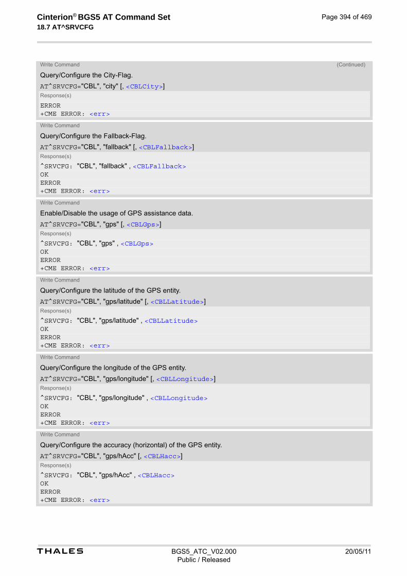
t BGS5_ATC_V02.000 20/05/11Public / Released
Cinterion® BGS5 AT Command Set 18.7 AT^SRVCFG
Page 394 of 469
ERROR+CME ERROR: <err>
Write Command
Query/Configure the Fallback-Flag.
AT^SRVCFG="CBL", "fallback" [, <CBLFallback>]Response(s)
^SRVCFG: "CBL", "fallback" , <CBLFallback>OKERROR+CME ERROR: <err>
Write Command
Enable/Disable the usage of GPS assistance data.
AT^SRVCFG="CBL", "gps" [, <CBLGps>]Response(s)
^SRVCFG: "CBL", "gps" , <CBLGps>OKERROR+CME ERROR: <err>
Write Command
Query/Configure the latitude of the GPS entity.
AT^SRVCFG="CBL", "gps/latitude" [, <CBLLatitude>]Response(s)
^SRVCFG: "CBL", "gps/latitude" , <CBLLatitude>OKERROR+CME ERROR: <err>
Write Command
Query/Configure the longitude of the GPS entity.
AT^SRVCFG="CBL", "gps/longitude" [, <CBLLongitude>]Response(s)
^SRVCFG: "CBL", "gps/longitude" , <CBLLongitude>OKERROR+CME ERROR: <err>
Write Command
Query/Configure the accuracy (horizontal) of the GPS entity.
AT^SRVCFG="CBL", "gps/hAcc" [, <CBLHacc>]Response(s)
^SRVCFG: "CBL", "gps/hAcc" , <CBLHacc>OKERROR+CME ERROR: <err>
Write Command (Continued)
Query/Configure the City-Flag.
AT^SRVCFG="CBL", "city" [, <CBLCity>]Response(s)
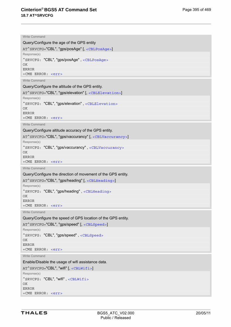
t BGS5_ATC_V02.000 20/05/11Public / Released
Cinterion® BGS5 AT Command Set 18.7 AT^SRVCFG
Page 395 of 469
Write Command
Query/Configure the age of the GPS entity
AT^SRVCFG="CBL", "gps/posAge" [, <CBLPosAge>]Response(s)
^SRVCFG: "CBL", "gps/posAge" , <CBLPosAge>OKERROR+CME ERROR: <err>
Write Command
Query/Configure the altitude of the GPS entity.
AT^SRVCFG="CBL", "gps/elevation" [, <CBLElevation>]Response(s)
^SRVCFG: "CBL", "gps/elevation" , <CBLElevation>OKERROR+CME ERROR: <err>
Write Command
Query/Configure altitude accuracy of the GPS entity.
AT^SRVCFG="CBL", "gps/vaccurancy" [, <CBLVaccurancy>]Response(s)
^SRVCFG: "CBL", "gps/vaccurancy" , <CBLVaccurancy>OKERROR+CME ERROR: <err>
Write Command
Query/Configure the direction of movement of the GPS entity.
AT^SRVCFG="CBL", "gps/heading" [, <CBLHeading>]Response(s)
^SRVCFG: "CBL", "gps/heading" , <CBLHeading>OKERROR+CME ERROR: <err>
Write Command
Query/Configure the speed of GPS location of the GPS entity.
AT^SRVCFG="CBL", "gps/speed" [, <CBLSpeed>]Response(s)
^SRVCFG: "CBL", "gps/speed" , <CBLSpeed>OKERROR+CME ERROR: <err>
Write Command
Enable/Disable the usage of wifi assistance data.
AT^SRVCFG="CBL", "wifi" [, <CBLWifi>]Response(s)
^SRVCFG: "CBL", "wifi" , <CBLWifi>OKERROR+CME ERROR: <err>

t BGS5_ATC_V02.000 20/05/11Public / Released
Cinterion® BGS5 AT Command Set 18.7 AT^SRVCFG
Page 396 of 469
Write Command
Query/Configure the BSSID for the wifi entity.
AT^SRVCFG="CBL", "wifi/bssid" [, <CBLBssid>]Response(s)
^SRVCFG: "CBL", "wifi/bssid" , <CBLBssid>OKERROR+CME ERROR: <err>
Write Command
Query/Configure the SSID for the wifi entity.
AT^SRVCFG="CBL", "wifi/ssid" [, <CBLSsid>]Response(s)
^SRVCFG: "CBL", "wifi/ssid" , <CBLSsid>OKERROR+CME ERROR: <err>
Write Command
Query/Configure the measured signal strength for the wifi entity.
AT^SRVCFG="CBL", "wifi/rssid" [, <CBLRssid>]Response(s)
^SRVCFG: "CBL", "wifi/rssid" , <CBLRssid>OKERROR+CME ERROR: <err>
Write Command
Query the SensorLogic Service settings.
AT^SRVCFG="SLAE", "read" , <filename>Response(s)
In case of success:^SRVCFG: "SLAE", "read" , <key>, <key_value>OKIn case of error:ERROR^SRVCFG: "SLAE", "read" , 1 , <filename>does not exist.
Write Command
Configure/Validate SensorLogic Service settings. Note that the settings can only be configured manually and then validated through the AT^SRVCFG="SLAE", "write" command.
AT^SRVCFG="SLAE", "write" , <filename>Response(s)
In case of success:^SRVCFG: "SLAE", "write" , <filename>OKIn case of error:ERROR^SRVCFG: "SLAE", "write" , 1 , <filename>does not exist.
PIN Last
- - -

t BGS5_ATC_V02.000 20/05/11Public / Released
Cinterion® BGS5 AT Command Set 18.7 AT^SRVCFG
Page 397 of 469
Parameter Description
COMBAIN service key
Combain's licence key which is the crucial token to access the COMBAIN service. The maximal length of the string is 20.
Interval of the repeated location service in minutes
This parameter number of minutes between two location requests enabled with AT^SRVCTL. When errors occur during the requesting service, this parameter would be reset to "0". If the value is "0", launching the service with AT^SRVCTL triggers a one-time positioning request in non-blocking mode.
0(D)...1440
City information
Setting can be used to control whether the city information is shown in the response if available.
0(D) Disable city flag.
1 Enable city flag.
Fallback switch
This parameter enables or disables the fallback solution which serves as an alternative method to positioning while the cell information is not found. Beware that the returned location may be unreliable.
0(D) Disable fallback solution.
1 Enable fallback solution.
GPS assistance data
This parameter determines whether the GPS assistance data are used for location calculation. Only when all the mandatory parameters of the GPS entity are set, this parameter can be changed to "1". In addition, if the parameter is "1", the configuration of the GPS entity cannot be modified. Note that this parameter will be reset to "0", after the GPS entity has been used.
0(D) Do not use GPS assistance data for location requests.
1 Using GPS assistance data for next location request. This setting will be auto-matically reset <CBLUrc>=0 after next successful location request.
Latitude of the GPS entity
Latitude is a mandatory value for the GPS entity. Its default value is empty (""). The value can be set in the format "45.62154". This parameter is effective only if <CBLGps> is 1, and can be modified only when <CBLGps> is 0. Note that this parameter will be reset to "0", after the GPS entity has been used.
"-90.00000"..."90.00000" A valid latitude of place
““(D) The latitude is not set
<CBLKey>(str)(NV)
<CBLUrc>(num)(NV)
<CBLCity>(num)(NV)
<CBLFallback>(num)(NV)
<CBLGps>(num)(NV)
<CBLLatitude>(str)(NV)
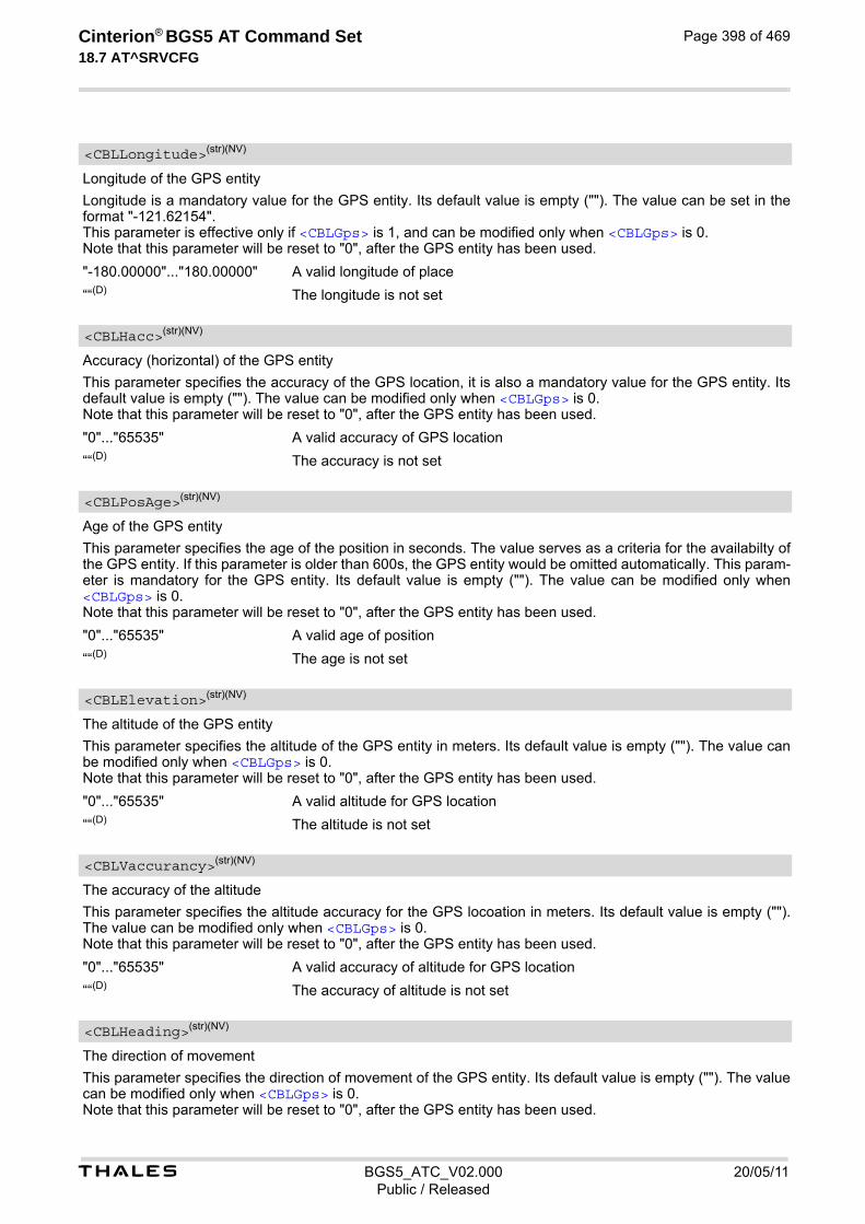
t BGS5_ATC_V02.000 20/05/11Public / Released
Cinterion® BGS5 AT Command Set 18.7 AT^SRVCFG
Page 398 of 469
Longitude of the GPS entity
Longitude is a mandatory value for the GPS entity. Its default value is empty (""). The value can be set in the format "-121.62154". This parameter is effective only if <CBLGps> is 1, and can be modified only when <CBLGps> is 0. Note that this parameter will be reset to "0", after the GPS entity has been used.
"-180.00000"..."180.00000" A valid longitude of place
““(D) The longitude is not set
Accuracy (horizontal) of the GPS entity
This parameter specifies the accuracy of the GPS location, it is also a mandatory value for the GPS entity. Its default value is empty (""). The value can be modified only when <CBLGps> is 0. Note that this parameter will be reset to "0", after the GPS entity has been used.
"0"..."65535" A valid accuracy of GPS location
““(D) The accuracy is not set
Age of the GPS entity
This parameter specifies the age of the position in seconds. The value serves as a criteria for the availabilty of the GPS entity. If this parameter is older than 600s, the GPS entity would be omitted automatically. This param-eter is mandatory for the GPS entity. Its default value is empty (""). The value can be modified only when <CBLGps> is 0. Note that this parameter will be reset to "0", after the GPS entity has been used.
"0"..."65535" A valid age of position
““(D) The age is not set
The altitude of the GPS entity
This parameter specifies the altitude of the GPS entity in meters. Its default value is empty (""). The value can be modified only when <CBLGps> is 0. Note that this parameter will be reset to "0", after the GPS entity has been used.
"0"..."65535" A valid altitude for GPS location
““(D) The altitude is not set
The accuracy of the altitude
This parameter specifies the altitude accuracy for the GPS locoation in meters. Its default value is empty (""). The value can be modified only when <CBLGps> is 0. Note that this parameter will be reset to "0", after the GPS entity has been used.
"0"..."65535" A valid accuracy of altitude for GPS location
““(D) The accuracy of altitude is not set
The direction of movement
This parameter specifies the direction of movement of the GPS entity. Its default value is empty (""). The value can be modified only when <CBLGps> is 0. Note that this parameter will be reset to "0", after the GPS entity has been used.
<CBLLongitude>(str)(NV)
<CBLHacc>(str)(NV)
<CBLPosAge>(str)(NV)
<CBLElevation>(str)(NV)
<CBLVaccurancy>(str)(NV)
<CBLHeading>(str)(NV)

t BGS5_ATC_V02.000 20/05/11Public / Released
Cinterion® BGS5 AT Command Set 18.7 AT^SRVCFG
Page 399 of 469
"0"..."65535" A valid direction for GPS location
““(D) The direction is not set
The speed of movement
This parameter specifies the speed of the GPS entity in m/s. Its default value is empty (""). The value can be modified only when <CBLGps> is 0. Note that this parameter will be reset to "0", after the GPS entity has been used.
"0"..."65535" A valid speed for GPS location
““(D) The speed is not set
Wifi assistance data
This parameter can be used to control Wifi assistance data to be calculated for positioning. Only all the manda-tory configurations for wifi were set, this parameter could be set to "1", at meantime configurations for Wifi would be locked. Note that this parameter would be reset to "0" automaically, after the GPS entity is used.
0(D) Do not use Wifi assistance data for location requests.
1 Using Wifi assistance data for next location request. This setting will be auto-matically reset to <CBLUrc>=0 after next uccessful location request.
The BSSID of the Wifi
This parameter indicates the MAC address of the Wifi router, e.g 00:50:56:C0:01. It is a mandatory configuration for Wifi, and default as empty (""). Note that this parameter will be reset to "", after the Wifi entity has been used.
““(D) The The BSSID of the Wifi is not set
The SSID of the Wifi
This parameter represents the name of Wifi access point. The maximal length of the string is 32. Note that this parameter will be reset to "", after the Wifi entity has been used.
““(D) The SSID of the Wifi is not set
The measured signal strength of the Wifi
This parameter denotes the received signal strength in dBm. Note that this parameter will be reset to "", after the Wifi entity has been used.
"-65535"..."0" A valid signal strength of the Wifi router
““(D) The signal strength of the Wifi router is not set
SensorLogic Configuration File
This parameter refers to the configuration files referenced by SensorLogic Service.
“MIDletInfo.config“ The required SensorLogic configuration file MIDletInfo.config
“ModuleServices.config“ The required SensorLogic configuration file ModuleServices.config
“SensorLogic.config“ The required SensorLogic configuration file SensorLogic.config
“SimAndNetwork.config“ The required SensorLogic configuration file SimAndNetwork.config
<CBLSpeed>(str)(NV)
<CBLWifi>(num)(NV)
<CBLBssid>(str)(NV)
<CBLSsid>(str)(NV)
<CBLRssid>(str)(NV)
<filename>(str)(NV)

t BGS5_ATC_V02.000 20/05/11Public / Released
Cinterion® BGS5 AT Command Set 18.7 AT^SRVCFG
Page 400 of 469
“AtWhiteList.atlist“ The optional SensorLogic configuration file AtWhiteList.atlist, which is not pre-installed by default, to get it from SensorLogic service provider
“AtBlackList.atlist“ The optional SensorLogic configuration file AtBlackList.atlist, which is not pre-installed by default, to get it from SensorLogic service provider
SensorLogic Configuration keys
This parameter refers to the configuration keys referenced by each <filename> (SensorLogic Service config-uration file). Each configuration file contains their different sets of keys. Please refer to each <filename> for details.
SensorLogic Configuration key values
This parameter refers to the value of each configuration key referenced by each <filename> (SensorLogic Service configuration file). Please refer to each <filename> for details.
Notes• The <CBLUrc> will be reset to "0" when any errors occur during the service.
• <CBLGps> and <CBLWifi> will be automatically reset to "0" after next successful location request.
• Only if mandatory configurations for gps/wifi are set, the corresponding mode can be set to 1. Configurations cannot be modified while the corresponding mode is 1.
Example Usage of "CBL":
<key>(str)(NV)
<key_value>(str)(NV)
AT+CSCS="UCS2" Switch to UCS2 character set.OKAT^SRVCFG="CBL","key","a2f2j4l6kj34lo12ppbg"
Set COMBAIN key.
^SRVCFG: "CBL","key","a2f2j4l6kj34lo12ppbg"OKAT^SRVCFG="CBL","key" Query COMBAIN key.^SRVCFG: "CBL","key","a2f2j4l6kj34lo12ppbg"OKAT^SRVCFG="CBL","urc",1 Activate URC mode.^SRVCFG: "CBL","urc",1OKAT^SRVCFG="CBL","urc" Query URC mode.^SRVCFG: "CBL","urc",1OKAT^SRVCFG="CBL","gps",1 Enable GPS assistance data without setting the
mandatory configurationsERRORAT^SRVCFG="CBL","gps/longitude","12.22334" Set mandatory configurations for GPS entity^SRVCFG: "CBL","gps/longitude","12.22334"OKAT^SRVCFG="CBL","gps/latitude","42.55564"^SRVCFG: "CBL","gps/latitude","42.55564"OKAT^SRVCFG="CBL","gps/hAcc","30"^SRVCFG: "CBL","gps/hAcc","30"OKAT^SRVCFG="CBL","gps/posAge","500"^SRVCFG: "CBL","gps/posAge","500"

t BGS5_ATC_V02.000 20/05/11Public / Released
Cinterion® BGS5 AT Command Set 18.7 AT^SRVCFG
Page 401 of 469
OKAT^SRVCFG="CBL","gps",1 Enable GPS assistance data with setting the manda-
tory configurations^SRVCFG: "CBL","gps",1OKAT^SRVCFG="CBL","wifi",1 Enable Wifi assistance data without setting the man-
datory configurationsERRORAT^SRVCFG="CBL","wifi/bssid","00:50:56:C0:00:01"
Set mandatory configurations for Wifi entity
^SRVCFG: "CBL","wifi/bssid","00:50:56:C0:00:01"OKAT^SRVCFG="CBL","wifi",1 Enable Wifi assistance data with setting the manda-
tory configurations^SRVCFG: "CBL","wifi",1OKAT^SRVCFG="CBL","wifi/bssid","00:50:56:C0:11:11"
When the configuration for Wifi is locked, you can reset the Wifi mode and then change the configura-tion
ERRORAT^SRVCFG="CBL","wifi",0^SRVCFG: "CBL","wifi",0OKAT^SRVCFG="CBL","wifi/bssid","00:50:56:C0:11:11"^SRVCFG: "CBL","wifi/bssid","00:50:56:C0:11:11"OK

t BGS5_ATC_V02.000 20/05/11Public / Released
Cinterion® BGS5 AT Command Set 18.8 AT^SRVCTL
Page 402 of 469
18.8 AT^SRVCTL Extra Service Control
AT^SRVCTL provides access to extra services. The following services are supported:
• COMBAIN cell based positioning: supporting the usage of cell (wifi/gps as assistance data) information to locate the module's position.
• SensorLogic Service: a M2M middleware service in JavaTM that seamlessly connects BGS5 modules to the SensorLogic Application Enablement Platform. The SL Agent exposes a set of easy-to-use JavaTM APIs for quick application development, allowing M2M solutions to be deployed in a fraction of the time.
SyntaxTest Command
AT^SRVCTL=?Response(s)
^SRVCTL: "CBL", (list of supported <CBLAction>) ^SRVCTL: "SLAE", (list of supported <SLAEAction>) OK
Write Command
Enable COMBAIN service.
AT^SRVCTL="CBL", "Enable"Response(s)
OKERROR+CME ERROR: <err>
Write Command
Disable COMBAIN service.
AT^SRVCTL="CBL" , "Disable"Response(s)
OKERROR+CME ERROR: <err>
Write Command
Query location in blocking mode.
AT^SRVCTL="CBL" , "Loc"Response(s)
In case of success:^SRVCTL: "CBL" , "Loc" , <CBLCode>, <CBLLatitude>, <CBLLongitude>, <CBLAccuracy>[, <CBLCountryCode>, <CBLCountry>, <CBLCity>]OKIn case of error:^SRVCTL: "CBL" , "Loc" , <CBLCode>, <CBLMessage>ERROR+CME ERROR: <err>
Write Command
Query the remaining number of credits of COMBAIN service.
AT^SRVCTL="CBL" , "Crd"Response(s)
In case of success:^SRVCTL: "CBL" , "Crd" , <CBLCode>, <CBLCrd>OK

t BGS5_ATC_V02.000 20/05/11Public / Released
Cinterion® BGS5 AT Command Set 18.8 AT^SRVCTL
Page 403 of 469
In case of error:^SRVCTL: "CBL" , "Crd" , <CBLCode>, <CBLMessage>ERROR+CME ERROR: <err>
Write Command
Start a positioning service. Result will be reported via URC (if enabled with <CBLUrc> parameter of AT^SRVCFG).
AT^SRVCTL="CBL" , "Start" Response(s)
In case of success:OKIn case of error:^SRVCTL: "CBL" , "Loc" , <CBLCode>, <CBLMessage>ERROR+CME ERROR: <err>
Write Command
Stop the running positioning service.
AT^SRVCTL="CBL" , "Stop" Response(s)
In case of success:OKIn case of error:^SRVCTL: "CBL" , "Loc" , <CBLCode>, <CBLMessage>ERROR+CME ERROR: <err>
Write Command
Start the SensorLogic Service.
AT^SRVCTL="SLAE" , "Start" Response(s)
In case of success:^SRVCFG: "SLAE", "start" , 0 OKIn case of error:^SRVCFG: "SLAE" , "start" , 1 , <SLAEMessage>
Write Command
Stop the SensorLogic Service.
AT^SRVCTL="SLAE" , "Stop" Response(s)
In case of success:^SRVCFG: "SLAE", "Stop" , 0 OKIn case of error:^SRVCFG: "SLAE" , "Stop" , 1 , <SLAEMessage>
PIN Last
- - -
Write Command (Continued)
Query the remaining number of credits of COMBAIN service.
AT^SRVCTL="CBL" , "Crd"Response(s)
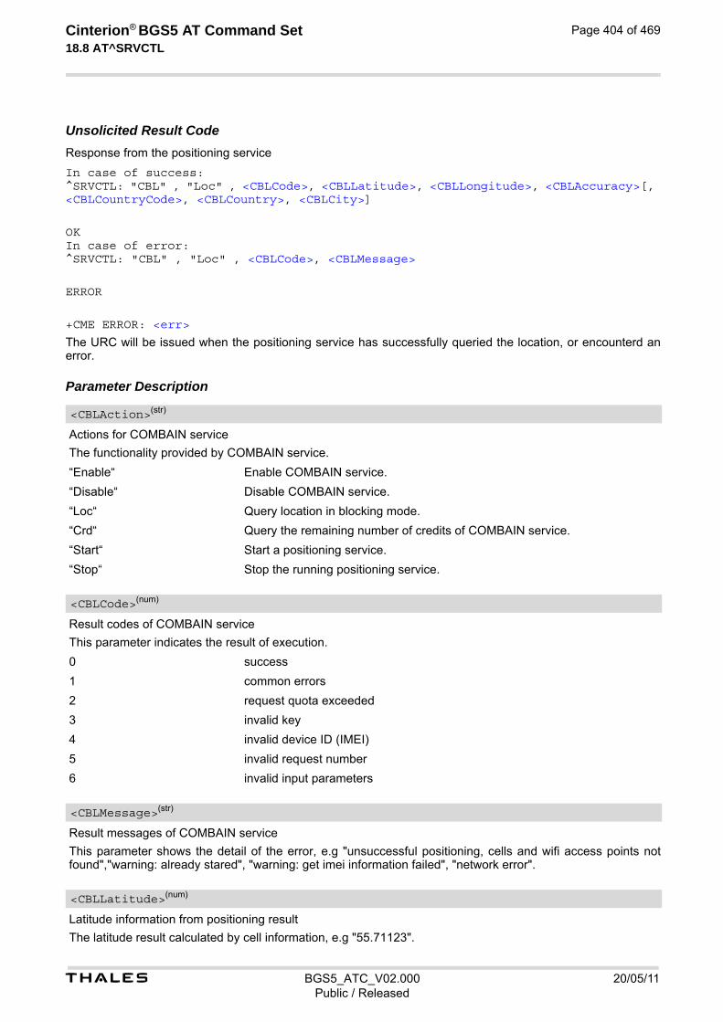
t BGS5_ATC_V02.000 20/05/11Public / Released
Cinterion® BGS5 AT Command Set 18.8 AT^SRVCTL
Page 404 of 469
Unsolicited Result CodeResponse from the positioning service
In case of success:^SRVCTL: "CBL" , "Loc" , <CBLCode>, <CBLLatitude>, <CBLLongitude>, <CBLAccuracy>[, <CBLCountryCode>, <CBLCountry>, <CBLCity>]
OKIn case of error:^SRVCTL: "CBL" , "Loc" , <CBLCode>, <CBLMessage>
ERROR
+CME ERROR: <err>
The URC will be issued when the positioning service has successfully queried the location, or encounterd an error. Parameter Description
Actions for COMBAIN service
The functionality provided by COMBAIN service.
“Enable“ Enable COMBAIN service.
“Disable“ Disable COMBAIN service.
“Loc“ Query location in blocking mode.
“Crd“ Query the remaining number of credits of COMBAIN service.
“Start“ Start a positioning service.
“Stop“ Stop the running positioning service.
Result codes of COMBAIN service
This parameter indicates the result of execution.
0 success
1 common errors
2 request quota exceeded
3 invalid key
4 invalid device ID (IMEI)
5 invalid request number
6 invalid input parameters
Result messages of COMBAIN service
This parameter shows the detail of the error, e.g "unsuccessful positioning, cells and wifi access points not found","warning: already stared", "warning: get imei information failed", "network error".
Latitude information from positioning result
The latitude result calculated by cell information, e.g "55.71123".
<CBLAction>(str)
<CBLCode>(num)
<CBLMessage>(str)
<CBLLatitude>(num)
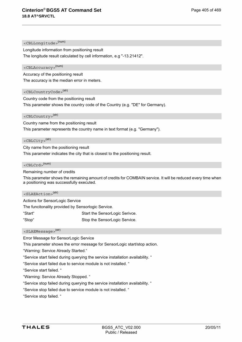
t BGS5_ATC_V02.000 20/05/11Public / Released
Cinterion® BGS5 AT Command Set 18.8 AT^SRVCTL
Page 405 of 469
Longitude information from positioning result
The longitude result calculated by cell information, e.g "-13.21412".
Accuracy of the positioning result
The accuracy is the median error in meters.
Country code from the positioning result
This parameter shows the country code of the Country (e.g. "DE" for Germany).
Country name from the positioning result
This parameter represents the country name in text format (e.g. "Germany").
City name from the positioning result
This parameter indicates the city that is closest to the positioning result.
Remaining number of credits
This parameter shows the remaining amount of credits for COMBAIN service. It will be reduced every time when a positioning was successfully executed.
Actions for SensorLogic Service
The funcitonality provided by Sensorlogic Service.
“Start“ Start the SensorLogic Serivce.
“Stop“ Stop the SensorLogic Service.
Error Message for SensorLogic Service
This parameter shows the error message for SensorLogic start/stop action.
“Warning: Service Already Started.“
“Service start failed during querying the service installation availability. “
“Service start failed due to service module is not installed. “
“Service start failed. “
“Warning: Service Already Stopped. “
“Service stop failed during querying the service installation availability. “
“Service stop failed due to service module is not installed. “
“Service stop failed. “
<CBLLongitude>(num)
<CBLAccuracy>(num)
<CBLCountryCode>(str)
<CBLCountry>(str)
<CBLCity>(str)
<CBLCrd>(num)
<SLAEAction>(str)
<SLAEMessage>(str)
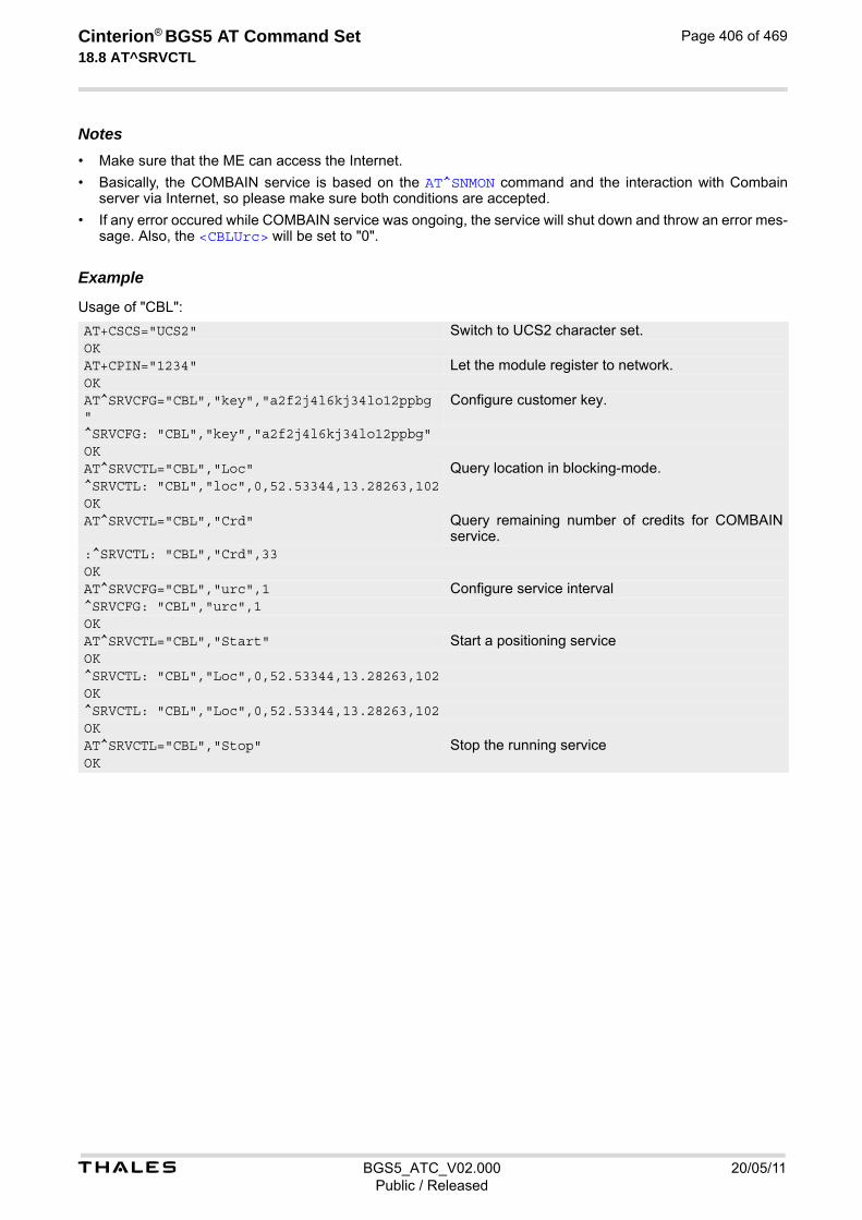
t BGS5_ATC_V02.000 20/05/11Public / Released
Cinterion® BGS5 AT Command Set 18.8 AT^SRVCTL
Page 406 of 469
Notes• Make sure that the ME can access the Internet.
• Basically, the COMBAIN service is based on the AT^SNMON command and the interaction with Combain server via Internet, so please make sure both conditions are accepted.
• If any error occured while COMBAIN service was ongoing, the service will shut down and throw an error mes-sage. Also, the <CBLUrc> will be set to "0".
Example Usage of "CBL":
AT+CSCS="UCS2" Switch to UCS2 character set.OKAT+CPIN="1234" Let the module register to network.OKAT^SRVCFG="CBL","key","a2f2j4l6kj34lo12ppbg"
Configure customer key.
^SRVCFG: "CBL","key","a2f2j4l6kj34lo12ppbg"OKAT^SRVCTL="CBL","Loc" Query location in blocking-mode.^SRVCTL: "CBL","loc",0,52.53344,13.28263,102OKAT^SRVCTL="CBL","Crd" Query remaining number of credits for COMBAIN
service.:^SRVCTL: "CBL","Crd",33OKAT^SRVCFG="CBL","urc",1 Configure service interval^SRVCFG: "CBL","urc",1OKAT^SRVCTL="CBL","Start" Start a positioning serviceOK^SRVCTL: "CBL","Loc",0,52.53344,13.28263,102OK^SRVCTL: "CBL","Loc",0,52.53344,13.28263,102OKAT^SRVCTL="CBL","Stop" Stop the running serviceOK

Cinterion® BGS5 AT Command Set 19. Hardware related Commands
t BGS5_ATC_V02.000 20/05/11Public / Released
Page 407 of 469
19. Hardware related Commands
All AT commands described in this chapter are related to the hardware interface of the BGS5. Further information regarding this interface is available in the "BGS5 Hardware Interface Description" [2].
19.1 AT+CCLK Real Time Clock
The AT+CCLK write command sets the Real Time Clock in the ME. The AT+CCLK read command shows the time.
Syntax
Parameter Description
Format is "yy/mm/dd,hh:mm:ss", where the characters indicate the two last digits of the year, followed by month, day, hour, minutes, seconds; for example 6th of March 2018, 22:10:00 hours equals to "18/03/06,22:10:00" Factory default is "04/01/01,00:00:00"
Note• <time> is retained if the device enters the Power Down mode via AT^SMSO.
Test Command
AT+CCLK=?Response(s)
OK
Read Command
AT+CCLK?Response(s)
+CCLK: <time>OK
Write Command
AT+CCLK=<time>Response(s)
OKERROR+CME ERROR: <err>
PIN Last Reference(s)
- + - 3GPP TS 27.007 [43]
<time>(str)
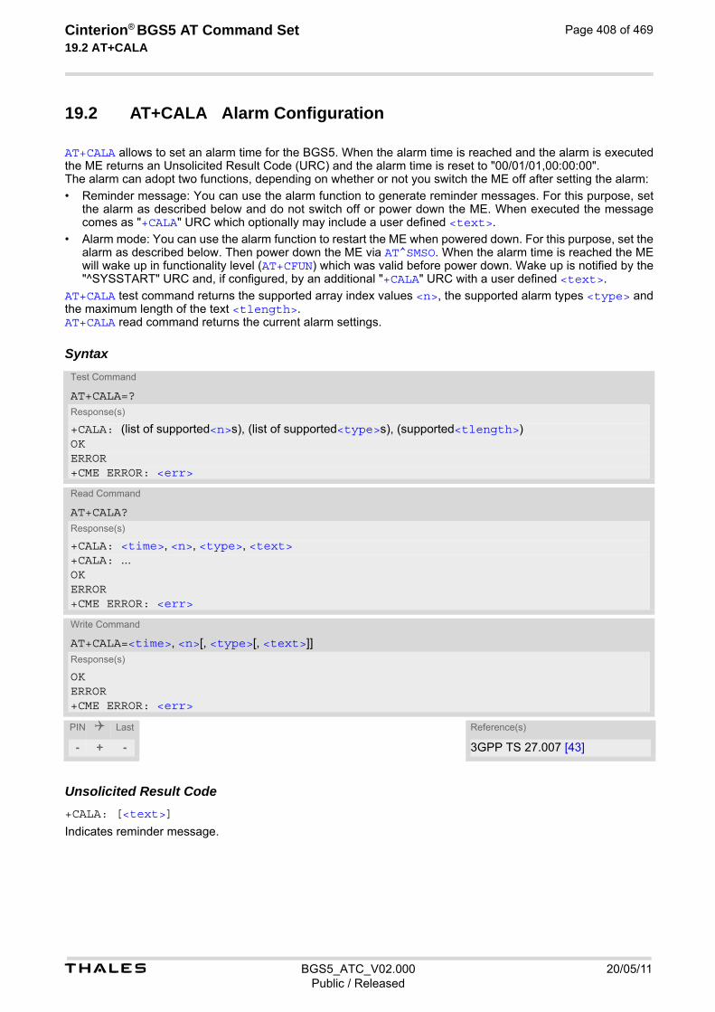
t BGS5_ATC_V02.000 20/05/11Public / Released
Cinterion® BGS5 AT Command Set 19.2 AT+CALA
Page 408 of 469
19.2 AT+CALA Alarm Configuration
AT+CALA allows to set an alarm time for the BGS5. When the alarm time is reached and the alarm is executed the ME returns an Unsolicited Result Code (URC) and the alarm time is reset to "00/01/01,00:00:00". The alarm can adopt two functions, depending on whether or not you switch the ME off after setting the alarm:
• Reminder message: You can use the alarm function to generate reminder messages. For this purpose, set the alarm as described below and do not switch off or power down the ME. When executed the message comes as "+CALA" URC which optionally may include a user defined <text>.
• Alarm mode: You can use the alarm function to restart the ME when powered down. For this purpose, set the alarm as described below. Then power down the ME via AT^SMSO. When the alarm time is reached the ME will wake up in functionality level (AT+CFUN) which was valid before power down. Wake up is notified by the "^SYSSTART" URC and, if configured, by an additional "+CALA" URC with a user defined <text>.
AT+CALA test command returns the supported array index values <n>, the supported alarm types <type> and the maximum length of the text <tlength>. AT+CALA read command returns the current alarm settings.
Syntax
Unsolicited Result Code+CALA: [<text>]
Indicates reminder message.
Test Command
AT+CALA=?Response(s)
+CALA: (list of supported<n>s), (list of supported<type>s), (supported<tlength>)OKERROR+CME ERROR: <err>
Read Command
AT+CALA?Response(s)
+CALA: <time>, <n>, <type>, <text>+CALA: ...OKERROR+CME ERROR: <err>
Write Command
AT+CALA=<time>, <n>[, <type>[, <text>]]Response(s)
OKERROR+CME ERROR: <err>
PIN Last Reference(s)
- + - 3GPP TS 27.007 [43]

t BGS5_ATC_V02.000 20/05/11Public / Released
Cinterion® BGS5 AT Command Set 19.2 AT+CALA
Page 409 of 469
Parameter Description
Format is "yy/MM/dd,hh:mm:ss". For example, 6th of July 2005, 22:10:00 equals to "05/07/06,22:10:00". See also AT+CCLK. If you attempt to set <time> to a date and time which is older than the ME's current time, one "+CALA" URC will be returned, and no alarm timer will be set. To clear a given alarm before its scheduled time simply enter an empty string for parameter <time>, but <text> will use previously saved text.
Integer type value indicating the array index of the alarm. 0 .. 4
Integer type value indicating the type of the alarm.
0 Alarm indication: text message via serial interface
String type value indicating the text to be displayed when alarm time is reached; maximum length is <tlength>. By factory default, <text> is undefined. Note: <text> will be stored to the non-volatile flash memory when the device enters the Power Down mode via AT^SMSO. Once saved, it will be available upon next power-up, until you overwrite it by typing another text. This eliminates the need to enter the full string when setting a fresh alarm. <text> should not contain characters which are coded differently in ASCII and GSM (e.g. umlauts), see also "Supported character sets" and "GSM alphabet tables".
Integer type value indicating the supported length range of <text>. The range is 1 to 16. Notes• After the alarm was executed the parameter <time> of AT+CALA will be reset to "00/01/01,00:00:00", but
<text> will be preserved as described above.
• If ME is totally disconnected from power supply the most recently saved configuration of +CALA: <time>,<n> [,<type>[,<text>]] will be presented when ME is powered up.
• When an alarm is set on a one of the AT command interfaces only this interface will be allowed for further AT+CALA read/write operations. Using the read/write AT+CALA command on another interface will result an ERROR until the last alarm timer was executed or deleted.
Examples EXAMPLE 1
You may want to configure a reminder message for July 31, 2005, at 9.30h, including the message "Good Morning".
Do not switch off the ME.When the alarm occurs the ME returns the following URC:
EXAMPLE 2
To set a fresh alarm using the same message as in Example 1, simply enter date, time and alarm index. <type> and <text> can be omitted:
<time>(str)
<n>(num)
<type>(num)
<text>(str)
<tlength>(num)
AT+CALA="05/07/31,09:30:00",0,0,"Good Morning"OK
+CALA: Good Morning

t BGS5_ATC_V02.000 20/05/11Public / Released
Cinterion® BGS5 AT Command Set 19.2 AT+CALA
Page 410 of 469
When the alarm is executed the URC comes with the same message:
EXAMPLE 3
To enable the ME to wake up into Alarm mode, e.g. on July 20, 2005, at 8.30h, enter
Next, power down the ME:
When the alarm is executed the ME wakes up to functionality level (AT+CFUN) which was valid before power down and displays a URC. If available, this line is followed by the individual <text> most recently saved. If no individual message was saved only the first line appears.
AT+CALA="05/07/31,08:50:00",0OK
+CALA: Good Morning
AT+CALA="05/07/20,08:30:00",0OK
AT^SMSO^SMSO: MS OFFOK^SHUTDOWN
^SYSSTART +CALA: Good Morning
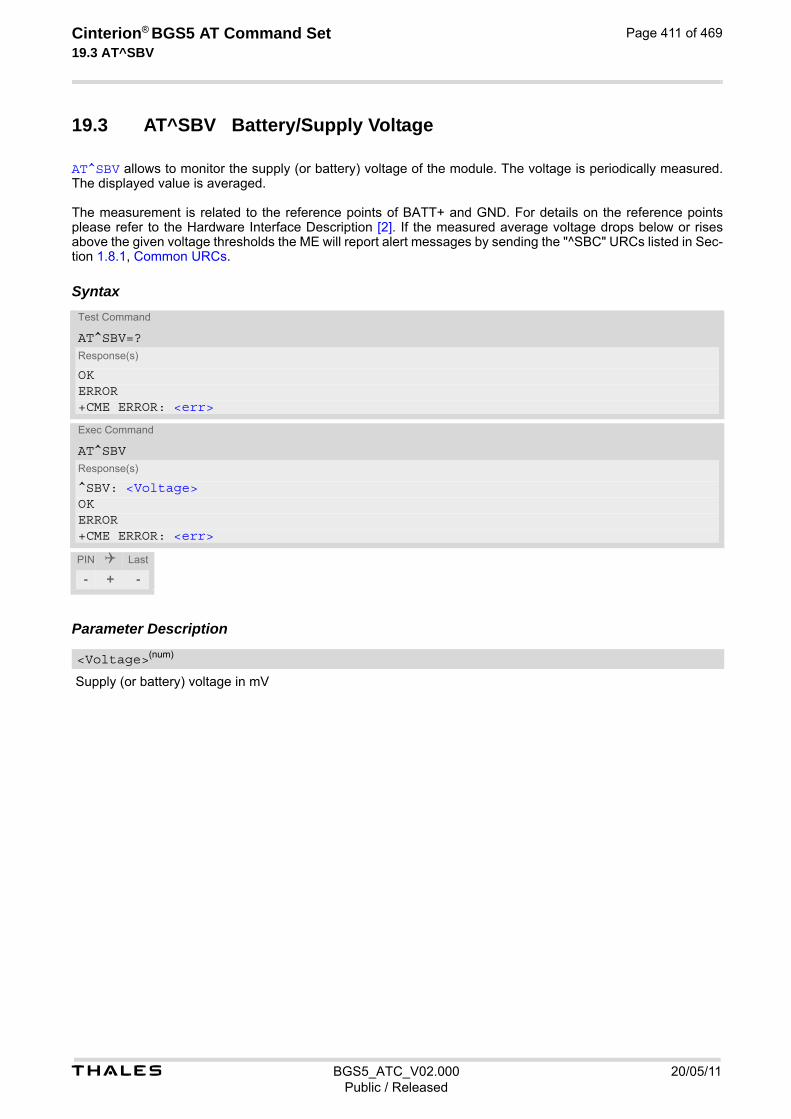
t BGS5_ATC_V02.000 20/05/11Public / Released
Cinterion® BGS5 AT Command Set 19.3 AT^SBV
Page 411 of 469
19.3 AT^SBV Battery/Supply Voltage
AT^SBV allows to monitor the supply (or battery) voltage of the module. The voltage is periodically measured. The displayed value is averaged. The measurement is related to the reference points of BATT+ and GND. For details on the reference points please refer to the Hardware Interface Description [2]. If the measured average voltage drops below or rises above the given voltage thresholds the ME will report alert messages by sending the "^SBC" URCs listed in Sec-tion 1.8.1, Common URCs.
Syntax
Parameter Description
Supply (or battery) voltage in mV
Test Command
AT^SBV=?Response(s)
OKERROR+CME ERROR: <err>
Exec Command
AT^SBVResponse(s)
^SBV: <Voltage>OKERROR+CME ERROR: <err>
PIN Last
- + -
<Voltage>(num)

t BGS5_ATC_V02.000 20/05/11Public / Released
Cinterion® BGS5 AT Command Set 19.4 AT^SCTM
Page 412 of 469
19.4 AT^SCTM Critical Operating Temperature Monitoring
AT^SCTM allows to monitor the operating temperature range of the BGS5 device. Refer to "BGS5 Hardware Interface Description" [2] for specifications on critical temperature ranges. To avoid damage the module will shut down once the critical temperature is exceeded. The procedure is equivalent to the power-down initiated with AT^SMSO. The AT^SCTM write command controls the presentation of URCs to report critical operating temperature limits. Use parameter <UrcMode> to enable (1) and disable (0) URC presentation. Each time after the BGS5 was switched on there is a guard period of 120 seconds. Until expiry of the guard timer, automatic thermal shutdown will be deferred and the presentation of all ^SCTM URC types is enabled even though <UrcMode> equals "0". URCs indicating alert levels "1" or "-1" are intended to enable the user to take precautions, such as protect the BGS5 from exposure to extreme conditions, or save or back up data etc. Except during the initial guard period after startup, the presentation of level "1", "-1" or "0" URCs depends on <UrcMode>. Level "2" or "-2" URCs are followed by immediate shutdown except during the initial guard period. The presen-tation of these URCs is always enabled, i.e. they will be output even though <UrcMode> equals "0". AT^SCTM read command returns:
• The URC presentation mode.
• Information about the current temperature range of the BGS5 device.
• The board temperature (in degree Celsius) if parameter <tempCtrl>=1.
Syntax
Test Command
AT^SCTM=?Response(s)
^SCTM:(list of supported <UrcMode>s)[, (list of supported <tempCtrl>s)]OK
Read Command
AT^SCTM?Response(s)
^SCTM: <UrcMode>, <UrcCause>[, <temp>]OKERROR+CME ERROR: <err>
Write Command
AT^SCTM=<UrcMode>[, <tempCtrl>]Response(s)
OKERROR+CME ERROR: <err>
PIN Last
- + -

t BGS5_ATC_V02.000 20/05/11Public / Released
Cinterion® BGS5 AT Command Set 19.4 AT^SCTM
Page 413 of 469
Unsolicited Result Codes
URC 1
URCs will be sent to the TE when the temperature reaches or exceeds the critical level, or when it is back to normal.
^SCTM_B: <UrcCause>
URC 2
URC indicated after "^SCTM_B" URC with <UrcCause> value 2 or -2 before the ME switches off.
^SHUTDOWN Parameter Description
URC presentation mode
0(P) Disable URC presentation (except for <UrcCause> equal to -2 or +2).
1 Enable URC presentation.
-2 Below lowest temperature limit (causes immediate switch-off)
-1 Below low temperature alert limit
0 Normal operating temperature
1 Above upper temperature alert limit
2 Above uppermost temperature limit (causes immediate switch-off)
0(P) Suppress output of <temp> in read command.
1 Output <temp> in read command.
Board temperature in Celsius. Is comprised between the lowest temperature warning level and the uppermost temperature warning level.
Examples EXAMPLE 1
URCs issued when the operating temperature is out of range:
EXAMPLE 2
URCs issued when the temperature is back to normal (URC is output once):
<UrcMode>(num)
<UrcCause>(num)
<tempCtrl>(num)
<temp>(num)
^SCTM_B: 1 Caution: Module close to overtemperature limit. ^SCTM_B: 2 Alert: Module is above overtemperature limit and switches off. ^SCTM_B: -1 Caution: Module close to undertemperature limit. ^SCTM_B: -2 Alert: Module is below undertemperature limit and switches off.
^SCTM_B: 0 Module back to normal temperature.

t BGS5_ATC_V02.000 20/05/11Public / Released
Cinterion® BGS5 AT Command Set 19.5 AT^SLED
Page 414 of 469
19.5 AT^SLED LED Feature
AT^SLED controls the LED function provided by the BGS5's STATUS pin, which acts as an output and can be used to control a connected LED. The AT^SLED command is functional only if LED functionality is enabled with AT^SCFG="Gpio/mode/SYNC" set to "std". The electrical specifications of the status pin and advice on how to connect the LED circuit can be found in [2]. The LED indicates the operating states listed below:
Table 19.1: BGS5 Status and Mode Indication via LED
Syntax
Parameter Description
LED operating mode
0(D) LED feature is disabled.
BGS5 Status <mode>=1 <mode>=2 <flash>= default
<mode>=2 <flash>= user defined
- GSM CS data call in progress or established - GSM voice call in progress or established
Permanently on 10 ms on / 990 ms off
<flash> ms on / 990 ms off
- GSM PS data transfer Permanently on 10 ms on / 1990 ms off
<flash> ms on / 1990 ms off
ME registered to a network. No call, no data transfer
Permanently on 10 ms on / 3990 ms off
<flash> ms on / 3990 ms off
Limited Network Service (e.g. because no SIM/USIM, no PIN or during network search)
500ms on / 500 ms off
500ms on / 500 ms off
500ms on / 500 ms off
Test Command
AT^SLED=?Response(s)
^SLED: (list of supported <mode>s), (range of supported <flash>s)OK
Read Command
AT^SLED?Response(s)
^SLED: <mode>[, <flash>]OK
Write Command
AT^SLED=<mode>[, <flash>]Response(s)
OKERROR+CME ERROR: <err>
PIN Last
- + -
<mode>(num)(NV)

t BGS5_ATC_V02.000 20/05/11Public / Released
Cinterion® BGS5 AT Command Set 19.5 AT^SLED
Page 415 of 469
1 LED lights steadily when the ME is registered to the network and either awake or in power saving state.
2 LED is flashing when the ME is in Limited Service or registered with a network and either awake or in power saving state. The duration of flashing can be con-figured using the parameter <flash>.
LED flash period
1...10(D)...50 LED flash period (in milliseconds) if <mode>=2. LED off-time between flashing is approximately 4 seconds and is not configu-rable.
<flash>(num)(NV)
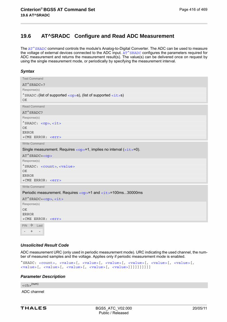
t BGS5_ATC_V02.000 20/05/11Public / Released
Cinterion® BGS5 AT Command Set 19.6 AT^SRADC
Page 416 of 469
19.6 AT^SRADC Configure and Read ADC Measurement
The AT^SRADC command controls the module's Analog-to-Digital Converter. The ADC can be used to measure the voltage of external devices connected to the ADC input. AT^SRADC configures the parameters required for ADC measurement and returns the measurement result(s). The value(s) can be delivered once on request by using the single measurement mode, or periodically by specifying the measurement interval.
Syntax
Unsolicited Result CodeADC measurement URC (only used in periodic measurement mode). URC indicating the used channel, the num-ber of measured samples and the voltage. Applies only if periodic measurement mode is enabled.
^SRADC: <count>, <value>[, <value>[, <value>[, <value>[, <value>[, <value>[, <value>[, <value>[, <value>[, <value>[, <value>]]]]]]]]]] Parameter Description
ADC channel
Test Command
AT^SRADC=?Response(s)
^SRADC:(list of supported <op>s), (list of supported <it>s)OK
Read Command
AT^SRADC?Response(s)
^SRADC: <op>, <it>OKERROR+CME ERROR: <err>
Write Command
Single measurement. Requires <op>=1, implies no interval (<it>=0).
AT^SRADC=<op>Response(s)
^SRADC: <count>, <value>OKERROR+CME ERROR: <err>
Write Command
Periodic measurement. Requires <op>=1 and <it>=100ms...30000ms
AT^SRADC=<op>, <it>Response(s)
OKERROR+CME ERROR: <err>
PIN Last
- + -
<ch>(num)
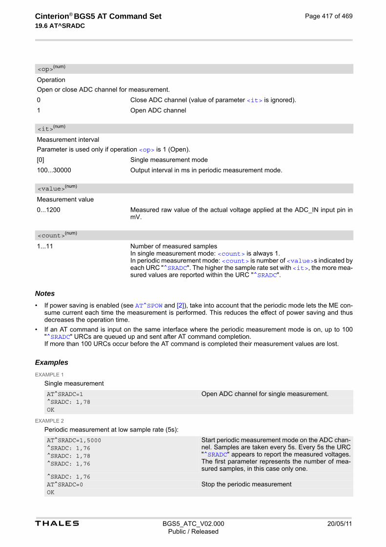
t BGS5_ATC_V02.000 20/05/11Public / Released
Cinterion® BGS5 AT Command Set 19.6 AT^SRADC
Page 417 of 469
Operation
Open or close ADC channel for measurement.
0 Close ADC channel (value of parameter <it> is ignored).
1 Open ADC channel
Measurement interval
Parameter is used only if operation <op> is 1 (Open).
[0] Single measurement mode
100...30000 Output interval in ms in periodic measurement mode.
Measurement value
0...1200 Measured raw value of the actual voltage applied at the ADC_IN input pin in mV.
1...11 Number of measured samples In single measurement mode: <count> is always 1. In periodic measurement mode: <count> is number of <value>s indicated by each URC "^SRADC". The higher the sample rate set with <it>, the more mea-sured values are reported within the URC "^SRADC".
Notes• If power saving is enabled (see AT^SPOW and [2]), take into account that the periodic mode lets the ME con-
sume current each time the measurement is performed. This reduces the effect of power saving and thus decreases the operation time.
• If an AT command is input on the same interface where the periodic measurement mode is on, up to 100 "^SRADC" URCs are queued up and sent after AT command completion. If more than 100 URCs occur before the AT command is completed their measurement values are lost.
Examples EXAMPLE 1
Single measurement
EXAMPLE 2
Periodic measurement at low sample rate (5s):
<op>(num)
<it>(num)
<value>(num)
<count>(num)
AT^SRADC=1 Open ADC channel for single measurement.^SRADC: 1,78OK
AT^SRADC=1,5000 Start periodic measurement mode on the ADC chan-nel. Samples are taken every 5s. Every 5s the URC "^SRADC" appears to report the measured voltages. The first parameter represents the number of mea-sured samples, in this case only one.
^SRADC: 1,76^SRADC: 1,78^SRADC: 1,76
^SRADC: 1,76AT^SRADC=0 Stop the periodic measurementOK
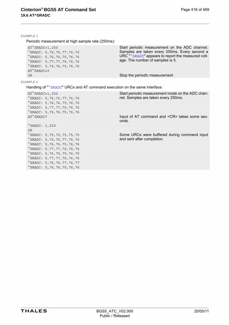
t BGS5_ATC_V02.000 20/05/11Public / Released
Cinterion® BGS5 AT Command Set 19.6 AT^SRADC
Page 418 of 469
EXAMPLE 3
Periodic measurement at high sample rate (250ms):
EXAMPLE 4
Handling of "^SRADC" URCs and AT command execution on the same interface:
AT^SRADC=1,250 Start periodic measurement on the ADC channel. Samples are taken every 250ms. Every second a URC "^SRADC" appears to report the measured volt-age. The number of samples is 5.
^SRADC: 5,76,76,77,76,76^SRADC: 5,76,76,75,76,76^SRADC: 5,77,77,76,76,76^SRADC: 5,76,76,75,76,76AT^SRADC=0OK Stop the periodic measurement
AT^SRADC=1,250 Start periodic measurement mode on the ADC chan-nel. Samples are taken every 250ms.^SRADC: 5,76,76,77,76,76
^SRADC: 5,76,76,75,76,76^SRADC: 5,77,77,76,76,76^SRADC: 5,76,76,75,76,76AT^SRADC? Input of AT command and <CR> takes some sec-
onds.^SRADC: 1,250OK^SRADC: 5,75,75,75,75,75 Some URCs were buffered during command input
and sent after completion.^SRADC: 5,76,76,77,76,76^SRADC: 5,76,76,75,76,76^SRADC: 5,77,77,76,76,76^SRADC: 5,76,76,75,76,76^SRADC: 5,77,77,76,76,76^SRADC: 5,76,76,77,76,77^SRADC: 5,76,76,75,76,76

t BGS5_ATC_V02.000 20/05/11Public / Released
Cinterion® BGS5 AT Command Set 19.7 AT^SSPI
Page 419 of 469
19.7 AT^SSPI Serial Protocol Interface
The AT^SSPI command enables the module to be connected to external I²C or SPI devices. SPI lines are shared with GPIO lines or with the ASC0 line DSR0 and with ASC1 lines. Therefore, a connected SPI device is only accessible if AT^SCFG="Gpio/mode/SPI" is set to "std". Keep in mind that in this case the com-mands AT^SCFG="Gpio/mode/DSR0" and AT^SCFG="Gpio/mode/ASC1" automatically switch to "rsv". The I²C/SPI datastream is mapped through an internal I²C/SPI driver to and from an ASCII hex protocol which can be exchanged with an internal application (JAVA) or an external application via V24. The AT^SSPI write command configures and activates the I²C/SPI interface and changes from command mode into data mode. All values must be given in hexadecimal format (0 - 9, A - F) without "0x". For details on data mode please refer to Section 19.7.2, Transmitting Data over AT Interface. Caution: If I²C or SPI are opened from a Java application be sure to close the I²C or SPI channels before Java terminates. Otherwise I²C or SPI will be inaccessible unless you restart the ME.
Syntax
Test Command
AT^SSPI=?Response(s)
^SSPI:(list of supported <basicConfiguration>s), (list of supported <wordLength>s), (list of supported <extendedSpiConfiguration>s)OK
Read Command
AT^SSPI?Response(s)
^SSPI: <connectionState>, <basicConfiguration>, <wordLength>, <extendedSpiConfiguration>OKERROR+CME ERROR: <err>
Write Command
AT^SSPI=[<basicConfiguration>[, <wordLength>[, <extendedSpiConfiguration>]]]Response(s)
CONNECT(indicates that ME has entered data mode)ERROR+CME ERROR: <err>
PIN Last
- + +
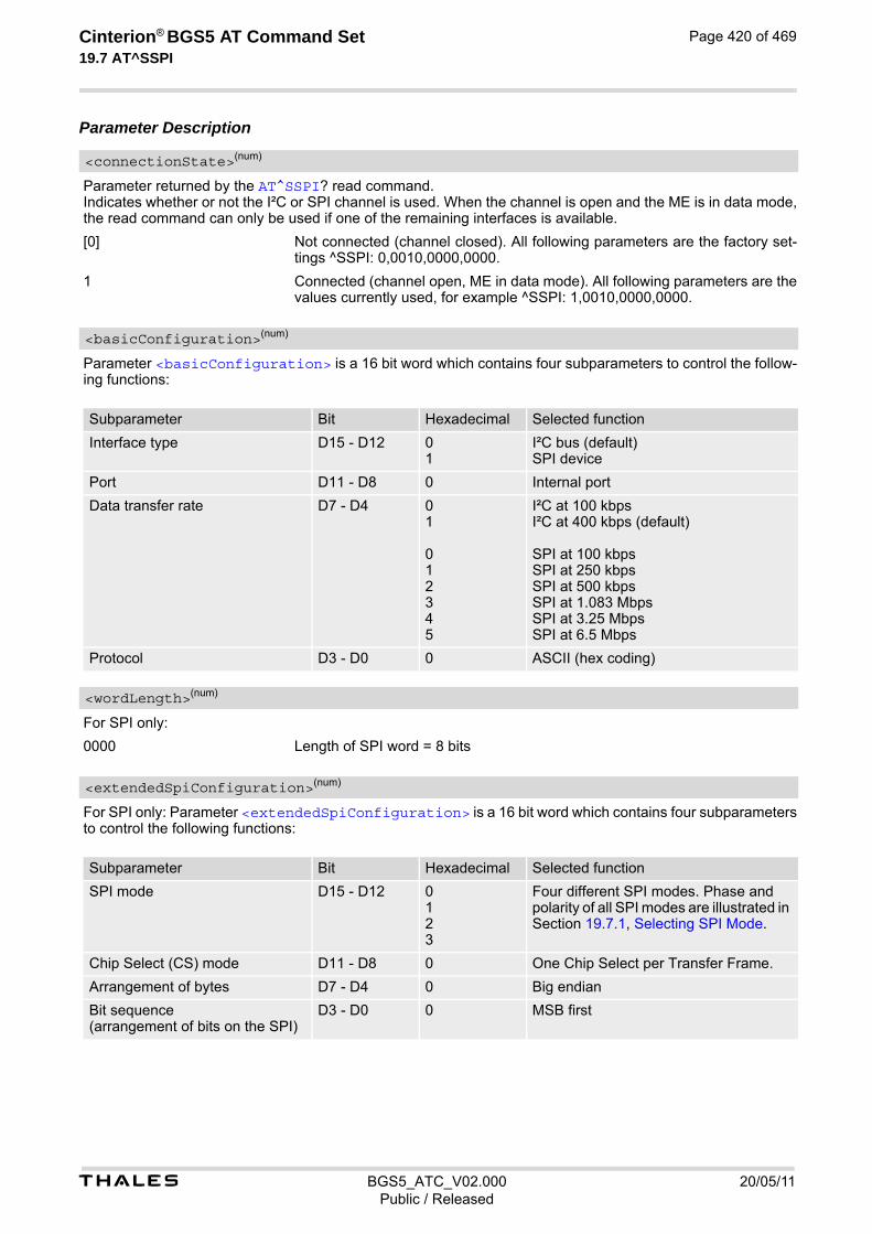
t BGS5_ATC_V02.000 20/05/11Public / Released
Cinterion® BGS5 AT Command Set 19.7 AT^SSPI
Page 420 of 469
Parameter Description
Parameter returned by the AT^SSPI? read command. Indicates whether or not the I²C or SPI channel is used. When the channel is open and the ME is in data mode, the read command can only be used if one of the remaining interfaces is available.
[0] Not connected (channel closed). All following parameters are the factory set-tings ^SSPI: 0,0010,0000,0000.
1 Connected (channel open, ME in data mode). All following parameters are the values currently used, for example ^SSPI: 1,0010,0000,0000.
Parameter <basicConfiguration> is a 16 bit word which contains four subparameters to control the follow-ing functions:
For SPI only:
0000 Length of SPI word = 8 bits
For SPI only: Parameter <extendedSpiConfiguration> is a 16 bit word which contains four subparameters to control the following functions:
<connectionState>(num)
<basicConfiguration>(num)
Subparameter Bit Hexadecimal Selected function
Interface type D15 - D12 0 1
I²C bus (default) SPI device
Port D11 - D8 0 Internal port
Data transfer rate D7 - D4 0 1 0 1 2 3 4 5
I²C at 100 kbps I²C at 400 kbps (default) SPI at 100 kbps SPI at 250 kbps SPI at 500 kbps SPI at 1.083 Mbps SPI at 3.25 Mbps SPI at 6.5 Mbps
Protocol D3 - D0 0 ASCII (hex coding)
<wordLength>(num)
<extendedSpiConfiguration>(num)
Subparameter Bit Hexadecimal Selected function
SPI mode D15 - D12 0 1 2 3
Four different SPI modes. Phase and polarity of all SPI modes are illustrated in Section 19.7.1, Selecting SPI Mode.
Chip Select (CS) mode D11 - D8 0 One Chip Select per Transfer Frame.
Arrangement of bytes D7 - D4 0 Big endian
Bit sequence (arrangement of bits on the SPI)
D3 - D0 0 MSB first

t BGS5_ATC_V02.000 20/05/11Public / Released
Cinterion® BGS5 AT Command Set 19.7 AT^SSPI
Page 421 of 469
19.7.1 Selecting SPI Mode
The figure shows the four types of SPI mode selectable by setting the appropriate hexadecimal value within the parameter <extendedSpiConfiguration>.
Figure 19.1: SPI modes selectable on SPI

t BGS5_ATC_V02.000 20/05/11Public / Released
Cinterion® BGS5 AT Command Set 19.7 AT^SSPI
Page 422 of 469
19.7.2 Transmitting Data over AT Interface
This section provides information on the protocol used for data transmission to or from I²C /SPI devices and explains the data mode. It is assumed that you are familiar with the I²C specification. Throughout this section the following document conventions are used to mark the direction of send and receive: Transfer Message: AT → I²C or SPI device driver Response Message: AT ← I²C or SPI device driver Channel Open / Close: To change from command mode to data mode use the AT^SSPI write command. To close down the channel and return to command mode send the ASCII code # (0x23). ASCII Protocol for I²C or SPI communication over AT interface: The protocol allows using a Terminal program for the communication between the module and the I²C slave device/SPI device. To visualize transferred characters and response data it is recommended to run the Terminal program in chat mode or to switch on local echo. For transfer and response, special characters are defined, such as Start and Stop to mark a single message and Close to disconnect the data channel. All valid special characters are listed below:
Table 19.2: Special characters for ASCII coding
Direction AT - Driver
Function in protocol Special character
Hex value Description
→ Start Transfer Message < 0x3C Special character sent to the I²C/SPI driver to start sending.
→ Stop Transfer Message > 0x3E Special character sent to the I²C/SPI driver to stop sending.
→ Channel Close # 0x23 For signalling. Channel Close can be sent any time inside or outside a transmit or receive message. Causes the transfer to be aborted and takes the ME back to AT command mode.
← Start Response Message { 0x7B Special character sent to the I²C/SPI driver to mark the beginning of a Response Message.
← Stop Response Message } 0x7D Special character sent to the I²C/SPI driver to mark the end of a Response Mes-sage.
← Protocol error ! 0x21 For signalling. Reports to the AT interface that the Trans-fer Frame does not comply with the proto-col definition (syntax error).
← Transmission OK (in I²C protocol referred to as ACK)
+ 0x2B Notifies the AT interface that data were successfully transmitted or, on the I²C bus, the I²C Slave Address was recognized.
On I²C bus only:
← Transmission error (in I²C protocol referred to as NAK)
- 0x2D Notifies the AT interface that data trans-mission failed or the I²C Slave Address was not recognized. On the I²C bus, the faulty data byte (16 bit byte counter) is identified as well.
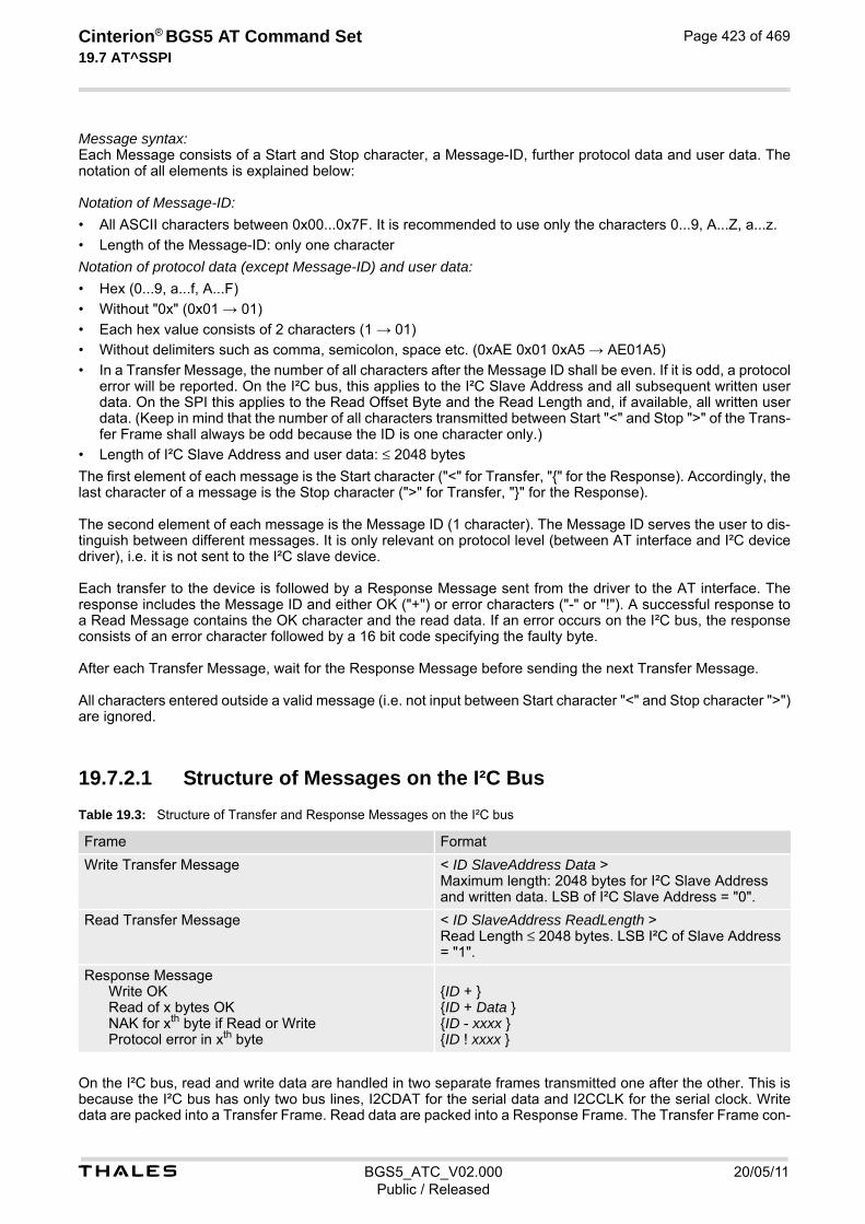
t BGS5_ATC_V02.000 20/05/11Public / Released
Cinterion® BGS5 AT Command Set 19.7 AT^SSPI
Page 423 of 469
Message syntax: Each Message consists of a Start and Stop character, a Message-ID, further protocol data and user data. The notation of all elements is explained below: Notation of Message-ID:
• All ASCII characters between 0x00...0x7F. It is recommended to use only the characters 0...9, A...Z, a...z.
• Length of the Message-ID: only one character
Notation of protocol data (except Message-ID) and user data:
• Hex (0...9, a...f, A...F)
• Without "0x" (0x01 → 01)
• Each hex value consists of 2 characters (1 → 01)
• Without delimiters such as comma, semicolon, space etc. (0xAE 0x01 0xA5 → AE01A5)
• In a Transfer Message, the number of all characters after the Message ID shall be even. If it is odd, a protocol error will be reported. On the I²C bus, this applies to the I²C Slave Address and all subsequent written user data. On the SPI this applies to the Read Offset Byte and the Read Length and, if available, all written user data. (Keep in mind that the number of all characters transmitted between Start "<" and Stop ">" of the Trans-fer Frame shall always be odd because the ID is one character only.)
• Length of I²C Slave Address and user data: ≤ 2048 bytes
The first element of each message is the Start character ("<" for Transfer, "{" for the Response). Accordingly, the last character of a message is the Stop character (">" for Transfer, "}" for the Response). The second element of each message is the Message ID (1 character). The Message ID serves the user to dis-tinguish between different messages. It is only relevant on protocol level (between AT interface and I²C device driver), i.e. it is not sent to the I²C slave device. Each transfer to the device is followed by a Response Message sent from the driver to the AT interface. The response includes the Message ID and either OK ("+") or error characters ("-" or "!"). A successful response to a Read Message contains the OK character and the read data. If an error occurs on the I²C bus, the response consists of an error character followed by a 16 bit code specifying the faulty byte. After each Transfer Message, wait for the Response Message before sending the next Transfer Message. All characters entered outside a valid message (i.e. not input between Start character "<" and Stop character ">") are ignored.
19.7.2.1 Structure of Messages on the I²C Bus
Table 19.3: Structure of Transfer and Response Messages on the I²C bus
On the I²C bus, read and write data are handled in two separate frames transmitted one after the other. This is because the I²C bus has only two bus lines, I2CDAT for the serial data and I2CCLK for the serial clock. Write data are packed into a Transfer Frame. Read data are packed into a Response Frame. The Transfer Frame con-
Frame Format
Write Transfer Message < ID SlaveAddress Data > Maximum length: 2048 bytes for I²C Slave Address and written data. LSB of I²C Slave Address = "0".
Read Transfer Message < ID SlaveAddress ReadLength > Read Length ≤ 2048 bytes. LSB I²C of Slave Address = "1".
Response Message Write OK Read of x bytes OK NAK for xth byte if Read or Write Protocol error in xth byte
{ID + } {ID + Data } {ID - xxxx } {ID ! xxxx }
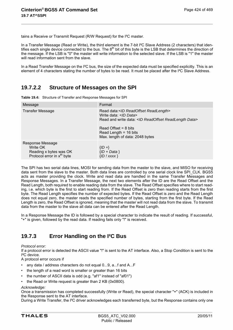
t BGS5_ATC_V02.000 20/05/11Public / Released
Cinterion® BGS5 AT Command Set 19.7 AT^SSPI
Page 424 of 469
tains a Receive or Transmit Request (R/W Request) for the I²C master. In a Transfer Message (Read or Write), the third element is the 7-bit I²C Slave Address (2 characters) that iden-tifies each single device connected to the bus. The 8th bit of this byte is the LSB that determines the direction of the message. If the LSB is "0" the master will write information to the selected slave. If the LSB is "1" the master will read information sent from the slave. In a Read Transfer Message on the I²C bus, the size of the expected data must be specified explicitly. This is an element of 4 characters stating the number of bytes to be read. It must be placed after the I²C Slave Address.
19.7.2.2 Structure of Messages on the SPI
Table 19.4: Structure of Transfer and Response Messages for SPI
The SPI has two serial data lines, MOSI for sending data from the master to the slave, and MISO for receiving data sent from the slave to the master. Both data lines are controlled by one serial clock line SPI_CLK. BGS5 acts as master providing the clock. Write and read data are handled in the same Transfer Messages and Response Messages. In a Transfer Message, the next two elements after the ID are the Read Offset and the Read Length, both required to enable reading data from the slave. The Read Offset specifies where to start read-ing, i.e. which byte is the first to start reading from. If the Read Offset is zero then reading starts from the first byte. The Read Length specifies the number of expected bytes. If the Read Offset is zero and the Read Length does not equal zero, the master reads the specified number of bytes, starting from the first byte. If the Read Length is zero, the Read Offset is ignored, meaning that the master will not read data from the slave. To transmit data from the master to the slave all data can be entered after the Read Length. In a Response Message the ID is followed by a special character to indicate the result of reading. If successful, "+" is given, followed by the read data. If reading fails only "!" is received.
19.7.3 Error Handling on the I²C Bus
Protocol error: If a protocol error is detected the ASCII value "!" is sent to the AT interface. Also, a Stop Condition is sent to the I²C device. A protocol error occurs if
• any data / address characters do not equal 0...9, a...f and A...F
• the length of a read word is smaller or greater than 16 bits
• the number of ASCII data is odd (e.g. "af1" instead of "af01")
• the Read or Write request is greater than 2 KB (0x0800).
Acknowledge: Once a transmission has completed successfully (Write or Read), the special character "+" (ACK) is included in the Response sent to the AT interface. During a Write Transfer, the I²C driver acknowledges each transferred byte, but the Response contains only one
Message Format
Transfer Message Read data:<ID ReadOffset ReadLength> Write data: <ID Data> Read and write data: <ID ReadOffset ReadLength Data> Read Offset = 8 bits Read Length = 16 bits Max. length of data: 2048 bytes
Response Message Write OK Reading x bytes was OK Protocol error in xth byte
{ID +} {ID + Data } {ID ! xxxx }

t BGS5_ATC_V02.000 20/05/11Public / Released
Cinterion® BGS5 AT Command Set 19.7 AT^SSPI
Page 425 of 469
ACK which is transmitted only if all bytes are successfully transferred. During a Read Transfer, an ACK is sent when the I²C slave device notifies that it has recognized the I²C Slave Address. Not Acknowledge: During a Transmit Transfer, a NAK is given when the I²C Slave Device notifies a failure to receive either the I²C Slave Address or a data byte. In this case, a Stop Condition is sent to the I²C device. During a Receive Transfer, a NAK is transmitted only when the I²C does not receive any reponse for the I²C Slave Address. The I²C device never acknowledges the validity of the received data (by sending an ACK the master acknowledges each received byte to the slave).

t BGS5_ATC_V02.000 20/05/11Public / Released
Cinterion® BGS5 AT Command Set 19.7 AT^SSPI
Page 426 of 469
19.7.4 Example: Using I²C Bus
As stated above, it is recommended to run the Terminal program in chat mode or to use the local echo. First, activate the I²C interface:
The module is in data mode now. This allows you to send a Write Transfer Message:
To quit data mode and return to command mode enter the Close character "#":
If the ME is in command mode, the response to the read command contains the factory settings.
If the ME is in data mode, the response to the read command contains the current settings.
AT^SSPI=0010,0000,0000 The first group of characters forms the <basicCon-figuration>, where the first "0" sets I²C, the sec-ond "0" is the internal port, the digit "1" sets 400 kbps bit rate on the I²C bus, and the next "0" selects ASCII coding. Note: If omitted all above parameters are assumed by default. Therefore, instead of AT^SSPI=0010,0000,0000 it is sufficient to enter only AT^SSPI=
CONNECT
<aAE000102030405060708090A0B0C0D0E0F> Write Transfer Frame, where a = ID, AE = Slave Address and write request.
{a+} Write Response Message, where a = ID.<bAF0010> Read Transfer Message, where b = ID, AF = Slave
Address and read request, 0010 = number of expected bytes.
{b+000102030405060708090A0B0C0D0E0F} Read Response Message, where b = ID.
#OK The response OK confirms that the ME is back to
command mode and ready to accept any AT com-mands.
AT^SSPI?^SSPI: 0,0010,0000,0000 The read command returns the connection state "not
connected" (Channel closed) and the factory set-tings for I²C.
OK
AT^SSPI?^SSPI: 1,0010,0000,0000 The read command returns the connection state
"connected" (Channel open) and the current settings for I²C.
OK

t BGS5_ATC_V02.000 20/05/11Public / Released
Cinterion® BGS5 AT Command Set 19.7 AT^SSPI
Page 427 of 469
19.7.5 Example: Transfer and Response Messages on SPI
The following examples shall illustrate the message structure and write/read procedures explained in Section 19.7.2.2, Structure of Messages on the SPI. Blanks are inserted only to better visualize frame elements. In prac-tice no blanks are allowed.
<0 00 0000 06> Transfer Message: The master enable write to slave. {0 +} Response Message: Transmission successful.
<0 00 0000 02 00 11 22 33> Transfer Message: The master writes 3 bytes. {0 +} Response Message: Transmission successful.
<1 00 0010 03 00> Transfer Message: The master requests to read 16 bytes from the slave. Read Offset is zero, therefore, reading starts from the first byte.
{1 + FF FF 11 22 33 78 99 99 99 CC CC CC CA AA AB BB}
Response Message: Reading data successful.
<2 02 0008 03 00> Transfer Message: The master requests to read 8 bytes from the slave. Read Offset is 2, therefore, reading starts from the third byte.
{2 + 11 22 33 78 99 99 99 CC} Response Message: Reading data successful.
<3 03 0004 03 00 11 22 33 44 55 66> Transfer Message: The master writes 6 bytes and requests to read 4 bytes from the slave. Read Offset is 3, therefore, reading starts from the fourth byte.
{3 + 22 33 78 99} Response Message: Reading and writing data suc-cessful.
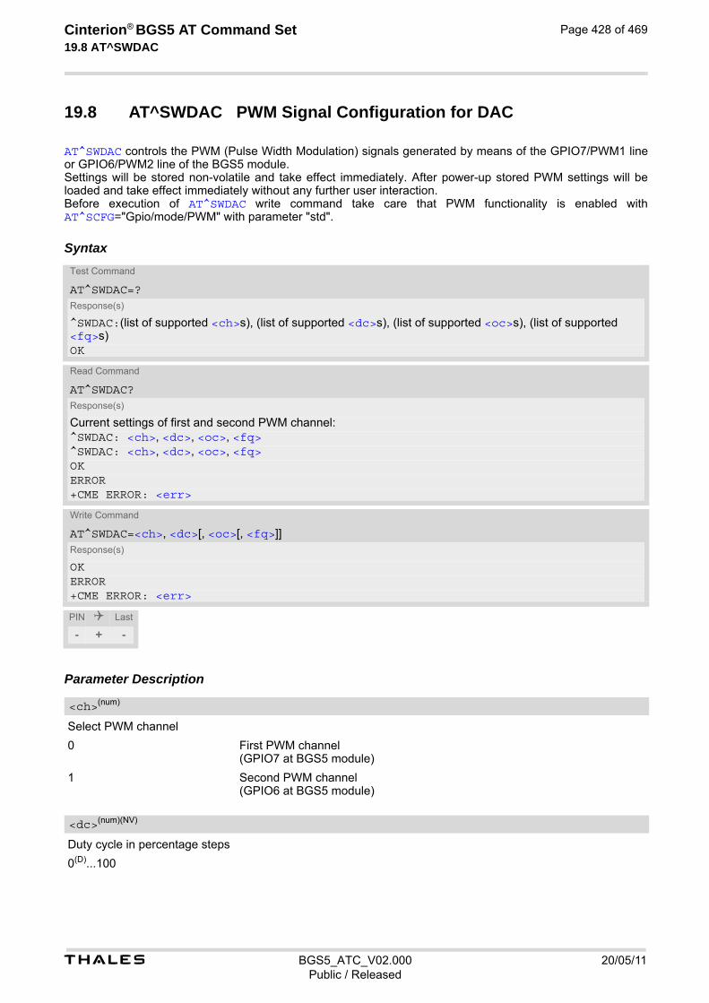
t BGS5_ATC_V02.000 20/05/11Public / Released
Cinterion® BGS5 AT Command Set 19.8 AT^SWDAC
Page 428 of 469
19.8 AT^SWDAC PWM Signal Configuration for DAC
AT^SWDAC controls the PWM (Pulse Width Modulation) signals generated by means of the GPIO7/PWM1 line or GPIO6/PWM2 line of the BGS5 module. Settings will be stored non-volatile and take effect immediately. After power-up stored PWM settings will be loaded and take effect immediately without any further user interaction. Before execution of AT^SWDAC write command take care that PWM functionality is enabled with AT^SCFG="Gpio/mode/PWM" with parameter "std".
Syntax
Parameter Description
Select PWM channel
0 First PWM channel (GPIO7 at BGS5 module)
1 Second PWM channel (GPIO6 at BGS5 module)
Duty cycle in percentage steps
0(D)...100
Test Command
AT^SWDAC=?Response(s)
^SWDAC:(list of supported <ch>s), (list of supported <dc>s), (list of supported <oc>s), (list of supported <fq>s)OK
Read Command
AT^SWDAC?Response(s)
Current settings of first and second PWM channel:^SWDAC: <ch>, <dc>, <oc>, <fq>^SWDAC: <ch>, <dc>, <oc>, <fq>OKERROR+CME ERROR: <err>
Write Command
AT^SWDAC=<ch>, <dc>[, <oc>[, <fq>]]Response(s)
OKERROR+CME ERROR: <err>
PIN Last
- + -
<ch>(num)
<dc>(num)(NV)

t BGS5_ATC_V02.000 20/05/11Public / Released
Cinterion® BGS5 AT Command Set 19.8 AT^SWDAC
Page 429 of 469
Open or close DAC
0(D) Close DAC
1 Open DAC
PWM frequency
0(D) 400 Hz (accuracy of 1 percentage step)
1 1000 Hz (accuracy of 3 percentage steps)
2 8,125 Hz (accuracy of 1 percentage step)
3 16,250 Hz (accuracy of 1 percentage step)
4 32,500 Hz (accuracy of 1 percentage step)
5 65,000 Hz (accuracy of 2 percentage steps) Note• Once the PWM channel is opened with a certain duty cycle and frequency, only changing the duty cycle while
using the same frequency is permitted. However, to change the frequency first close the PWM channel, and then open it again with new frequency.
Example This example shows how to open the GPIO7/PWM1 output and change the duty cycle while using the same fre-quency.
<oc>(num)(NV)
<fq>(num)(NV)
AT^SWDAC=0,50,1,2 Initial opening of GPIO7/PWM1, while setting PWM signal to 8,125 Hz at 50% duty cycle.
OKAT^SWDAC=0,75 Change duty cycle of the open GPIO7/PWM1 output.OKAT^SWDAC=0,80 Change duty cycle of the open GPIO7/PWM1 output.OKAT^SWDAC=0,0,0 Close GPIO7/PWM1 output.OK

Cinterion® BGS5 AT Command Set 20. General Purpose I/O (GPIO) Pin related Commands
t BGS5_ATC_V02.000 20/05/11Public / Released
Page 430 of 469
20. General Purpose I/O (GPIO) Pin related Commands
This chapter describes the AT commands used to access and configure the GPIO pins of BGS5. Please also refer to [2] for electrical specifications of the GPIO pins.
20.1 AT^SCPIN Pin Configuration
The AT^SCPIN write command serves to add (or remove) and configure GPIO lines. Keep in mind that some GPIO lines share functions with other interfaces. For details see AT^SCFG "GPIO/mode/xxx" settings, Section 20.1.1, GPIO Configuration Table and following AT commands: AT^SLED, AT^SCCNT, AT^SWDAC, AT^SSPI, AT^SCFG "MEShutdown/Fso".
Syntax
Parameter Description
0 Close GPIO line
1 Open GPIO line
Pin identifier
0 GPIO1
1 GPIO2
2 GPIO3
3 GPIO4
4 GPIO5
5 GPIO6
6 GPIO7
7 GPIO8
Test Command
AT^SCPIN=?Response(s)
^SCPIN:(list of supported <mode>s), (list of supported <pin_id>s), (list of supported <direction>s), (list of supported <startValue>s)OK
Write Command
AT^SCPIN=<mode>, <pin_id>, <direction>[, <startValue>]Response(s)
OKERROR+CME ERROR: <err>
PIN Last
- + -
<mode>(num)
<pin_id>(num)
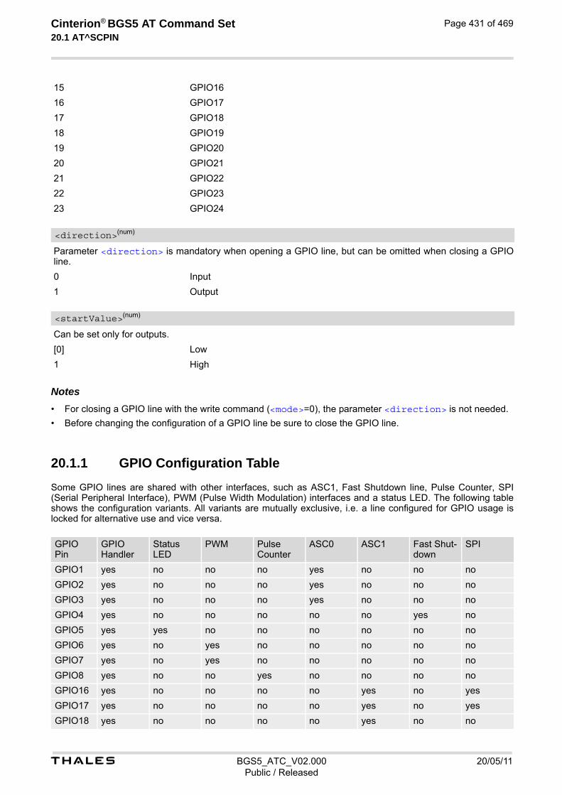
t BGS5_ATC_V02.000 20/05/11Public / Released
Cinterion® BGS5 AT Command Set 20.1 AT^SCPIN
Page 431 of 469
15 GPIO16
16 GPIO17
17 GPIO18
18 GPIO19
19 GPIO20
20 GPIO21
21 GPIO22
22 GPIO23
23 GPIO24
Parameter <direction> is mandatory when opening a GPIO line, but can be omitted when closing a GPIO line.
0 Input
1 Output
Can be set only for outputs.
[0] Low
1 High Notes• For closing a GPIO line with the write command (<mode>=0), the parameter <direction> is not needed.
• Before changing the configuration of a GPIO line be sure to close the GPIO line.
20.1.1 GPIO Configuration Table
Some GPIO lines are shared with other interfaces, such as ASC1, Fast Shutdown line, Pulse Counter, SPI (Serial Peripheral Interface), PWM (Pulse Width Modulation) interfaces and a status LED. The following table shows the configuration variants. All variants are mutually exclusive, i.e. a line configured for GPIO usage is locked for alternative use and vice versa.
<direction>(num)
<startValue>(num)
GPIO Pin
GPIO Handler
Status LED
PWM Pulse Counter
ASC0 ASC1 Fast Shut-down
SPI
GPIO1 yes no no no yes no no no
GPIO2 yes no no no yes no no no
GPIO3 yes no no no yes no no no
GPIO4 yes no no no no no yes no
GPIO5 yes yes no no no no no no
GPIO6 yes no yes no no no no no
GPIO7 yes no yes no no no no no
GPIO8 yes no no yes no no no no
GPIO16 yes no no no no yes no yes
GPIO17 yes no no no no yes no yes
GPIO18 yes no no no no yes no no
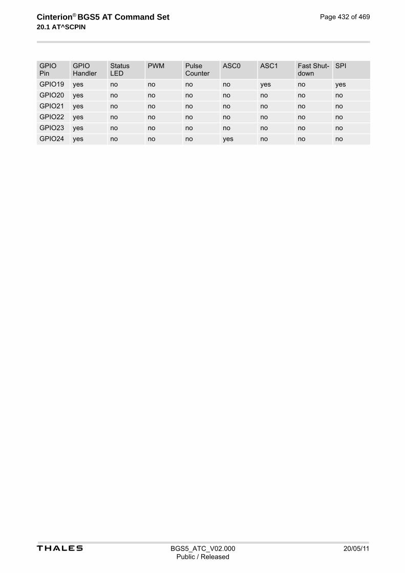
t BGS5_ATC_V02.000 20/05/11Public / Released
Cinterion® BGS5 AT Command Set 20.1 AT^SCPIN
Page 432 of 469
GPIO19 yes no no no no yes no yes
GPIO20 yes no no no no no no no
GPIO21 yes no no no no no no no
GPIO22 yes no no no no no no no
GPIO23 yes no no no no no no no
GPIO24 yes no no no yes no no no
GPIO Pin
GPIO Handler
Status LED
PWM Pulse Counter
ASC0 ASC1 Fast Shut-down
SPI

t BGS5_ATC_V02.000 20/05/11Public / Released
Cinterion® BGS5 AT Command Set 20.2 AT^SGIO
Page 433 of 469
20.2 AT^SGIO Get IO State of a Specified Pin
Syntax
Parameter Description
This is an already configured <pin_id> (see AT^SCPIN).
State read on this <io_id>.
0 Low for <pin_id>
1 High for <pin_id>
Test Command
AT^SGIO=?Response(s)
^SGIO:(list of supported <io_id>s)OK
Write Command
AT^SGIO=<io_id>Response(s)
^SGIO: <value>OKERROR+CME ERROR: <err>
PIN Last
- + -
<io_id>(num)
<value>(num)

t BGS5_ATC_V02.000 20/05/11Public / Released
Cinterion® BGS5 AT Command Set 20.3 AT^SSIO
Page 434 of 469
20.3 AT^SSIO Set IO State of a Specified Pin
Syntax
Parameter Description
This is an already configured <pin_id> (see AT^SCPIN).
State to be set for this <io_id>.
0 Low for <pin_id>
1 High for <pin_id>
Test Command
AT^SSIO=?Response(s)
^SSIO:(list of supported <io_id>s), (list of supported <value>s)OK
Write Command
AT^SSIO=<io_id>, <value>Response(s)
OKERROR+CME ERROR: <err>
PIN Last
- + -
<io_id>(num)
<value>(num)
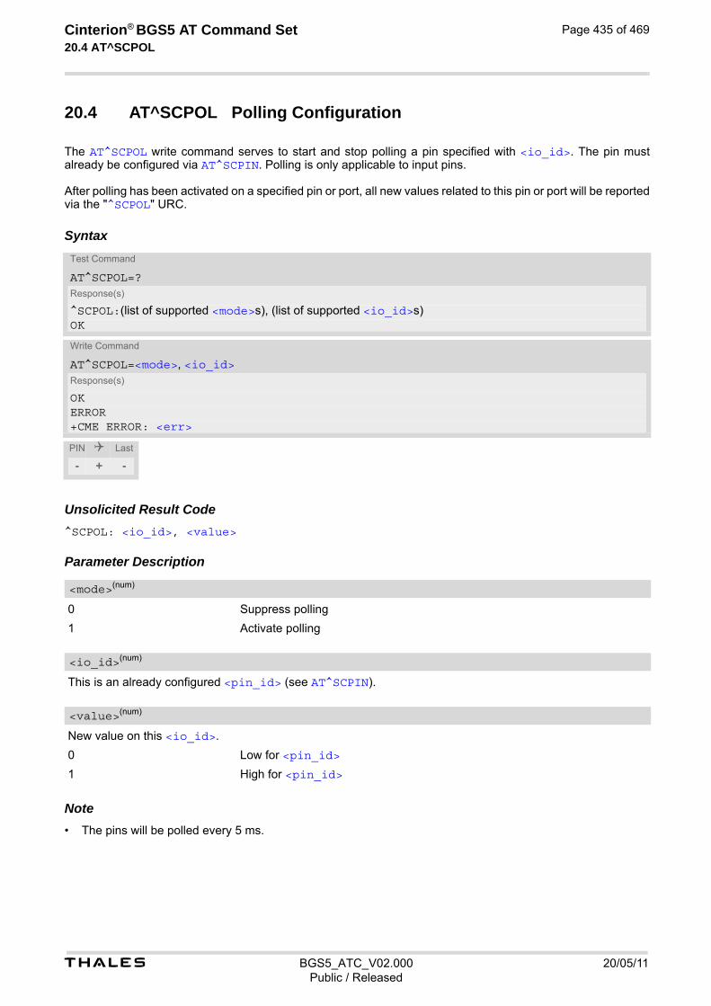
t BGS5_ATC_V02.000 20/05/11Public / Released
Cinterion® BGS5 AT Command Set 20.4 AT^SCPOL
Page 435 of 469
20.4 AT^SCPOL Polling Configuration
The AT^SCPOL write command serves to start and stop polling a pin specified with <io_id>. The pin must already be configured via AT^SCPIN. Polling is only applicable to input pins. After polling has been activated on a specified pin or port, all new values related to this pin or port will be reported via the "^SCPOL" URC.
Syntax
Unsolicited Result Code^SCPOL: <io_id>, <value> Parameter Description
0 Suppress polling
1 Activate polling
This is an already configured <pin_id> (see AT^SCPIN).
New value on this <io_id>.
0 Low for <pin_id>
1 High for <pin_id> Note• The pins will be polled every 5 ms.
Test Command
AT^SCPOL=?Response(s)
^SCPOL:(list of supported <mode>s), (list of supported <io_id>s)OK
Write Command
AT^SCPOL=<mode>, <io_id>Response(s)
OKERROR+CME ERROR: <err>
PIN Last
- + -
<mode>(num)
<io_id>(num)
<value>(num)

t BGS5_ATC_V02.000 20/05/11Public / Released
Cinterion® BGS5 AT Command Set 20.5 AT^SSCNT
Page 436 of 469
20.5 AT^SSCNT Start and Stop Pulse Counter
The AT^SSCNT write command serves to read, start, restart and stop the pulse counter.
Syntax
Unsolicited Result Code^SSCNT: <pulse>
The URC applies only to the Start-Stop mode set with AT^SCCNT, parameter <mode>=0. It is delivered once the pulse counter result was requested with <action>=2, or the pulse counter was stopped with <action>=3. The URC indicates the number of pulses counted. Parameter Description
This parameter can only be used after configuring the pulse counter with AT^SCCNT by using <action>= 1 to open pulse counter, otherwise the AT^SSCNT read and write command will return error. The <action> types 0, 1 and 2 apply only to the Start-Stop counter mode set with AT^SCCNT, parameter <mode>= 0.
0 Reset and start pulse counter from 0.
1 Restart pulse counter and continue counting from the <pulse> value of the last run.
2 Read out current <pulse> value.
Test Command
AT^SSCNT=?Response(s)
^SSCNT:(list of supported <action>s)OK
Read Command
AT^SSCNT?Response(s)
^SSCNT: <action>OKIf an error occurs:ERROR+CME ERROR: <err>
Write Command
AT^SSCNT=<action>Response(s)
If <action>=0 or 1:OKIf <action>=2 or 3:OK"^SSCNT" URC with parameter <pulse>If an error occurs:ERROR+CME ERROR: <err>
PIN Last
- + -
<action>(num)
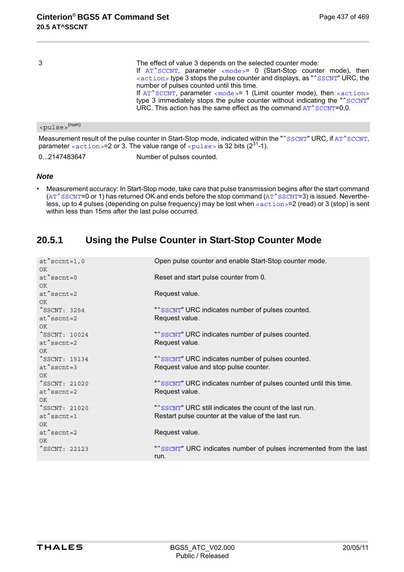
t BGS5_ATC_V02.000 20/05/11Public / Released
Cinterion® BGS5 AT Command Set 20.5 AT^SSCNT
Page 437 of 469
3 The effect of value 3 depends on the selected counter mode: If AT^SCCNT, parameter <mode>= 0 (Start-Stop counter mode), then <action> type 3 stops the pulse counter and displays, as "^SSCNT" URC, the number of pulses counted until this time. If AT^SCCNT, parameter <mode>= 1 (Limit counter mode), then <action> type 3 immediately stops the pulse counter without indicating the "^SCCNT" URC. This action has the same effect as the command AT^SCCNT=0,0.
Measurement result of the pulse counter in Start-Stop mode, indicated within the "^SSCNT" URC, if AT^SCCNT, parameter <action>=2 or 3. The value range of <pulse> is 32 bits (231-1).
0...2147483647 Number of pulses counted. Note• Measurement accuracy: In Start-Stop mode, take care that pulse transmission begins after the start command
(AT^SSCNT=0 or 1) has returned OK and ends before the stop command (AT^SSCNT=3) is issued. Neverthe-less, up to 4 pulses (depending on pulse frequency) may be lost when <action>=2 (read) or 3 (stop) is sent within less than 15ms after the last pulse occurred.
20.5.1 Using the Pulse Counter in Start-Stop Counter Mode
<pulse>(num)
at^sccnt=1,0 Open pulse counter and enable Start-Stop counter mode.OKat^sscnt=0 Reset and start pulse counter from 0.OKat^sscnt=2 Request value.OK^SSCNT: 3254 "^SSCNT" URC indicates number of pulses counted. at^sscnt=2 Request value.OK^SSCNT: 10024 "^SSCNT" URC indicates number of pulses counted. at^sscnt=2 Request value.OK^SSCNT: 15134 "^SSCNT" URC indicates number of pulses counted. at^sscnt=3 Request value and stop pulse counter.OK^SSCNT: 21020 "^SSCNT" URC indicates number of pulses counted until this time. at^sscnt=2 Request value.OK^SSCNT: 21020 "^SSCNT" URC still indicates the count of the last run. at^sscnt=1 Restart pulse counter at the value of the last run.OKat^sscnt=2 Request value.OK^SSCNT: 22123 "^SSCNT" URC indicates number of pulses incremented from the last
run.

t BGS5_ATC_V02.000 20/05/11Public / Released
Cinterion® BGS5 AT Command Set 20.6 AT^SCCNT
Page 438 of 469
20.6 AT^SCCNT Configure Pulse Counter
The AT^SCCNT write command serves to configure the GPIO8 line as pulse counter. The pulse counter is designed to measure signals from 0 to 1000 pulses per second. The measurement starts within <50ms after the OK result code has been sent. If the pulse counter is controlled from Java this delay may, in rare cases and depending on the system load, be longer. Before execution of the AT^SCCNT write command take care that Pulse Counter functionality is enabled with AT^SCFG="Gpio/mode/PULSE" set to "std". Remember that if the GPIO8 line is configured as GPIO (see AT^SCPIN) any attempt to activate the pulse counter will be rejected. Vice versa, if the pulse counter is opened the GPIO8 line cannot be configured as GPIO. See also [2] for further detail on the pulse counter.
Syntax
Unsolicited Result Code^SCCNT: <time>
The URC applies only to the Limit counter mode set with parameter <mode>=1. It is delivered once the pulse counter has completed counting the number of pulses requested with parameter <limit>. Parameter Description
0 Close pulse counter
1 Open pulse counter
Test Command
AT^SCCNT=?Response(s)
^SCCNT:(list of supported <action>s), (list of supported <mode>s), (list of supported <limit>s)OK
Read Command
AT^SCCNT?Response(s)
^SCCNT: <action>, <mode>[, <limit>]OKERROR+CME ERROR: <err>
Write Command
AT^SCCNT=<action>, <mode>[, <limit>]Response(s)
OKERROR+CME ERROR: <err>
PIN Last
- + -
<action>(num)

t BGS5_ATC_V02.000 20/05/11Public / Released
Cinterion® BGS5 AT Command Set 20.6 AT^SCCNT
Page 439 of 469
0 Activates the Start-Stop counter mode. After setting this mode, use AT^SSCNT and the <action> parameter to start or stop the pulse counter or to read out the measured pulses.
1 Activates the Limit counter mode and immediately starts the pulse counter. Parameter <limit> is mandatory for this mode.
1...65534 Number of pulses to be counted. Parameter <limit> applies only to the Limit counter mode and is mandatory for this mode. Once the given number of pulses is reached, the ME sends one single URC "^SCCNT" which indicates the parameter <time>.
1...2147483645 Time (in milliseconds) taken to count the number of pulses specified with <limit>. Measurement accuracy: The parameter <time> implies an inaccuracy <5ms which needs to be taken into account in addition to the measurement start-up time mentioned above.
20.6.1 Using the Pulse Counter in Limit Counter Mode
This example assumes that a 1 kHz frequency is applied at the GPIO8 line. Limit counter mode is enabled to request the time the pulse counter needs to count a specified number of pulses.
This example shows how to stop the Limit counter mode and close the pulse counter without waiting for the "^SCCNT" URC.
<mode>(num)
<limit>(num)
<time>(num)
at^sccnt=1,1,1000 Open pulse counter, enable Limit counter mode, request the time needed to count 1000 pulses.
OK^SCCNT: 1047 "^SCCNT" URC indicates the time taken to count 1000 pulses.at^sccnt=1,1,2000 Open pulse counter, enable Limit counter mode, request the time
needed to count 2000 pulses. OK^SCCNT: 2040 "^SCCNT" URC indicates the time taken to count 2000 pulses.at^sccnt=1,1,10000 Open pulse counter, enable Limit counter mode, request the time
needed to count 10000 pulses. OK^SCCNT: 10043 "^SCCNT" URC indicates the time taken to count 10000 pulses.at^sccnt=1,1,20000 Open pulse counter, enable Limit counter mode, request the time
needed to count 20000 pulses. OK^SCCNT: 20040 "^SCCNT" URC indicates the time taken to count 20000 pulses.
at^sccnt=0,0 Stop and close the pulse counter immediately, without "^SCCNT" URC being indicated.
OK
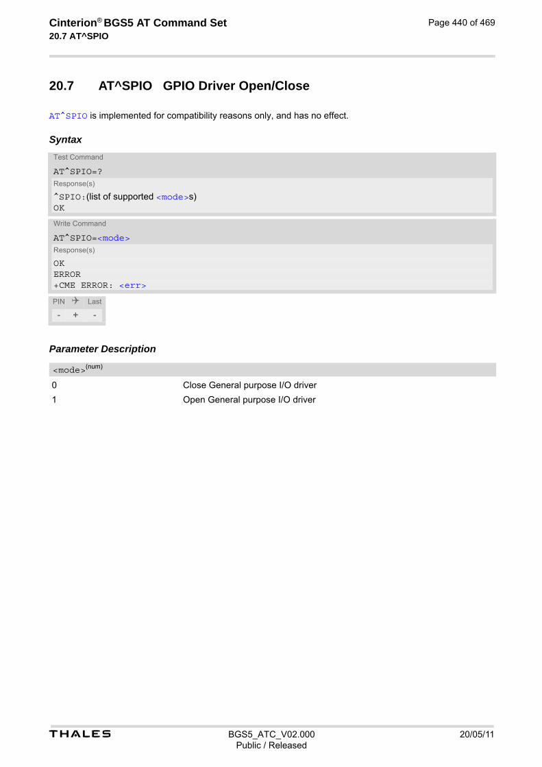
t BGS5_ATC_V02.000 20/05/11Public / Released
Cinterion® BGS5 AT Command Set 20.7 AT^SPIO
Page 440 of 469
20.7 AT^SPIO GPIO Driver Open/Close
AT^SPIO is implemented for compatibility reasons only, and has no effect.
Syntax
Parameter Description
0 Close General purpose I/O driver
1 Open General purpose I/O driver
Test Command
AT^SPIO=?Response(s)
^SPIO:(list of supported <mode>s)OK
Write Command
AT^SPIO=<mode>Response(s)
OKERROR+CME ERROR: <err>
PIN Last
- + -
<mode>(num)
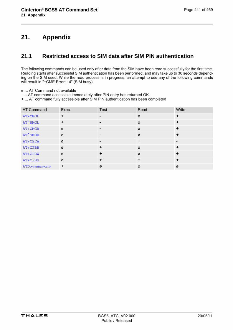
Cinterion® BGS5 AT Command Set 21. Appendix
t BGS5_ATC_V02.000 20/05/11Public / Released
Page 441 of 469
21. Appendix
21.1 Restricted access to SIM data after SIM PIN authentication
The following commands can be used only after data from the SIM have been read successfully for the first time. Reading starts after successful SIM authentication has been performed, and may take up to 30 seconds depend-ing on the SIM used. While the read process is in progress, an attempt to use any of the following commands will result in "+CME Error: 14" (SIM busy). ø ... AT Command not available - ... AT command accessible immediately after PIN entry has returned OK + ... AT command fully accessible after SIM PIN authentication has been completed
AT Command Exec Test Read Write
AT+CMGL + - ø +
AT^SMGL + - ø +
AT+CMGR ø - ø +
AT^SMGR ø - ø +
AT+CSCA ø - + -
AT+CPBR ø + ø +
AT+CPBW ø + ø +
AT+CPBS ø + + +
ATD><mem><n> + ø ø ø

t BGS5_ATC_V02.000 20/05/11Public / Released
Cinterion® BGS5 AT Command Set 21.2 Star-Hash (*#) Network Commands
Page 442 of 469
21.2 Star-Hash (*#) Network Commands
The following command strings can be sent by using ATD. The command strings are defined with 3GPP TS 22.030 [24].
Table 21.1: Star-Hash (*#) Command Overview
Star-Hash Code Functionality Response, also refer to Table 21.3
Phone Security
*#06# Query IMEI <IMEI> OK
**04[2]*oldPin[2]*newPin[2]*new-Pin[2]#
Change SIM pwd +CME ERROR: <err> / OK
**05[2]*unblKey[2]*newPin[2]*new-Pin[2]#
Change/Unblocking SIM pwd +CME ERROR: <err> / OK
*[*]03*[ZZ]*oldPw*newPw*newPw# Registration of net password +CME ERROR: <err> / OK
Phone number presentation
*#30# Check status of CLIP (Calling Line Identification Presentation)
+CLIP : <n>,<m> OK (see AT+CLIP)
*#31# Check status of CLIR (Calling Line Identification Restriction)
+CLIR : <n>,<m> OK (see AT+CLIR)
*31#<Phonenumber>[;] Suppress CLIR (see AT+CLIR)
#31#<Phonenumber>[;] Activate CLIR (see AT+CLIR)
*#76# Check status of COLP (Connected Line Identification Presentation)
+COLP : <n>,<m> OK (see: AT+COLP)
Call forwarding
(choice of *,#,*#,**,##)21*DN*BS# Act/deact/int/reg/eras CFU ^SCCFC : <reason>, <status>, <class> [,...] like +CCFC *) (see: AT+CCFC)
(choice of *,#,*#,**,##)67*DN*BS# Act/deact/int/reg/eras CF busy see above
(choice of *,#,*#,**,##)61*DN*BS*T#
Act/deact/int/reg/eras CF no reply see above
(choice of *,#,*#,**,##)62*DN*BS# Act/deact/int/reg/eras CF no reach see above
(choice of *,#,*#,**,##)002*DN*BS*T#
Act/deact/int/reg/eras CF all see above
(choice of *,#,*#,**,##)004*DN*BS*T#
Act/deact/int/reg/eras CF all cond. see above
Call waiting
(choice of *,#,*#)43*BS# Activation/deactivation/int WAIT +CCWA : <status>, <class> [,...] like +CCWA (see AT+CCWA)
Call barring
(choice of *,#,*#)33*Pw*BS# Act/deact/int BAOC ^SCLCK : <fac>, <status>, <class> [, ...] like +CLCK *) (Refer to AT+CLCK)
(choice of *,#,*#)331*Pw*BS# Act/deact/int BAOIC see above
(choice of *,#,*#)332*Pw*BS# Act/deact/int BAOIC exc.home see above

t BGS5_ATC_V02.000 20/05/11Public / Released
Cinterion® BGS5 AT Command Set 21.2 Star-Hash (*#) Network Commands
Page 443 of 469
*) Notes on ^SCCFC, +CCWA, ^SCLCK: The output depends on the affected basic service of the Star-Hash code. One line will be output for every tele- or bearer service coded in basic service code BS. ^SCCFC and ^SCLCK are modified by giving an additional <reason> or <fac> in front of the regular output string gener-ated by the standard commands +CCFC and +CLCK.
Table 21.2: Abbreviations of Codes and Parameters used in Table 21.1
Table 21.3: Star-Hash Command Response Parameters
(choice of *,#,*#)35*Pw*BS# Act/deact/int. BAIC see above
(choice of *,#,*#)351*Pw*BS# Act/deact/int BAIC roaming see above
#330*Pw*BS# Deact. All Barring Services see above
#333*Pw*BS# Deact. All Outg.Barring Services see above
#353*Pw*BS# Deact. All Inc.Barring Services see above
Call Hold / Multiparty
C[C] in call Call hold and multiparty +CME ERROR: <err> / OK
USSD messages
[C]...[C]# Send USSD message +CME ERROR: <err> / OK
C[C] (excluded 1[C]) Send USSD message +CME ERROR: <err> / OK
Abbreviation Meaning Value
ZZ Type of supplementary services: Barring services All services
330 Not specified
DN Dialing number String of digits 0-9
BS Basic service equivalent to parameter class: Voice FAX SMS SMS+FAX Data circuit asynchron Data circuit synchron dedicated PAD access dedicated Packet access Data circuit asynchron+PAD Data circuit synchron+Packet Data circuit asynchron+synchron+Packet+PAD All Services
11 13 16 12 25 24 27 26 21 22 20 --
T Time in seconds In contrast to AT+CCFC, parameter T has no default value. If T is not specified, an operator defined default or the last known value may be used, depending on the network operator.
PW Password --
C Character of TE character set (e.g. asterisk, hash or digit in case of USSD, or digits in case of held calls or multiparty calls)
--
Parameter Meaning
<m> Mode: 0 = not active, 1 = active
<n> Unsolicited result code: 0 = presentation disabled, 1 = presentation enabled
Star-Hash Code Functionality Response, also refer to Table 21.3

t BGS5_ATC_V02.000 20/05/11Public / Released
Cinterion® BGS5 AT Command Set 21.2 Star-Hash (*#) Network Commands
Page 444 of 469
For exact specification of format and parameters for Star-Hash commands refer to Table 3.2 of 3GPP TS 22.004 [23], and Annex C of of 3GPP TS 22.030 [24].
Table 21.4: Star-Hash Commands for Supplementary Services
<status> Status: 0 = not active, 1 = active
<class> Represents BS = basic service, refer to AT+CCFC, AT+CLCK
<fac> Facility lock, refer to AT+CLCK
<reason> Call forwarding reason
Star-Hash Code Abbreviations in Table 21.1 Functionality
* act Activate (except for CLIR, see list above)
** reg Register and activate
*# int Check status (interrogate)
# deact Deactivate (except for CLIR, see list above)
## eras Unregister and deactivate
Parameter Meaning

t BGS5_ATC_V02.000 20/05/11Public / Released
Cinterion® BGS5 AT Command Set 21.3 Available AT Commands and Dependency on SIM PIN
Page 445 of 469
21.3 Available AT Commands and Dependency on SIM PIN
ø ... Command not available- ... Command does not require PIN1+ ... Command requires PIN1± ... Command sometimes requires PIN1
Table 21.5: Available AT Commands and Dependency on SIM PIN
AT Command Exec Test Read Write
Configuration Commands
AT&F - ø ø ø
AT&V - ø ø ø
AT&W - ø ø ø
ATQ - ø ø ø
ATV - ø ø ø
ATX - ø ø ø
ATZ - ø ø ø
AT+CFUN ø - - -
AT^SMSO - - ø ø
AT+CMEE ø - - -
AT+CSCS ø - - -
AT^SCFG ø - - -
AT^SPOW ø - - -
Status Control Commands
AT+CEER - - ø -
AT^SIND ø - - -
AT+CPAS - - ø ø
Serial Interface Control Commands
AT\Q - ø ø ø
AT&C - ø ø ø
AT&D - ø ø ø
AT&S - ø ø ø
ATE - ø ø ø
AT+IPR ø - - -
AT+CMUX ø - - -
AT+ICF ø - - -
Identification Commands
ATI - ø ø ø
AT+CGMI - - ø ø
AT+CGMM - - ø ø
AT+CGMR - - ø ø

t BGS5_ATC_V02.000 20/05/11Public / Released
Cinterion® BGS5 AT Command Set 21.3 Available AT Commands and Dependency on SIM PIN
Page 446 of 469
AT+CGSN - - ø ø
AT+GSN - - ø ø
AT+CIMI + + ø ø
Security Commands
AT+CPIN ø - - -
AT+CPIN2 ø - - -
AT+CLCK ø - ø -
AT+CPWD ø + ø +
Call related Commands
ATA + ø ø ø
ATD ± ø ø ø
ATD><mem><n> + ø ø ø
ATD><n> + ø ø ø
ATD><str> + ø ø ø
ATDL + ø ø ø
ATH - ø ø ø
AT+CHUP + + ø ø
AT^SHUP ø + ø +
ATS0 ø ø - +
ATO - ø ø ø
+++ - ø ø ø
AT+CBST ø - - -
AT+CSTA ø - - -
AT+CRLP ø - - -
AT+CLCC + + ø ø
AT+CR ø + + +
AT+CRC ø - - -
ATS6 ø ø - -
ATS7 ø ø - -
ATS8 ø ø - -
ATS10 ø ø - -
Network Service Commands
AT+COPN + + ø ø
AT+COPS ø ± ± ±
AT+CREG ø - - -
AT+CSQ - - ø ø
AT+CPOL ø + + +
AT+CPLS ø + + +
AT+CTZR ø - - -
AT+CTZU ø - - -
AT Command Exec Test Read Write
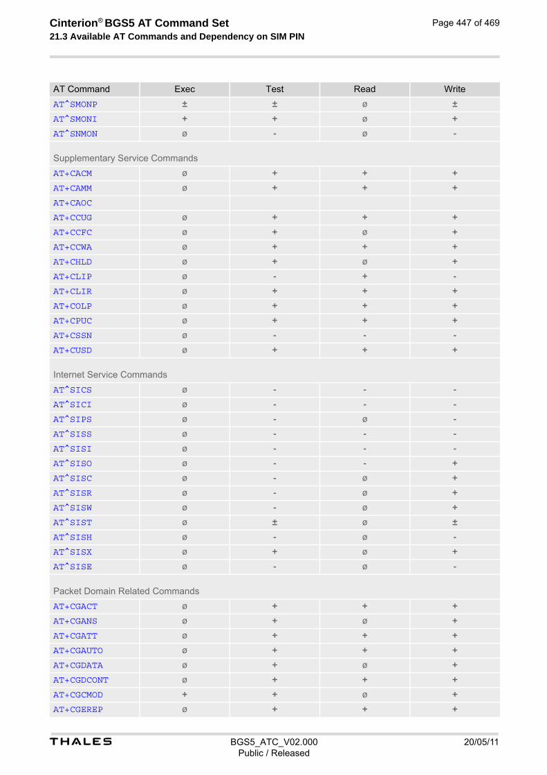
t BGS5_ATC_V02.000 20/05/11Public / Released
Cinterion® BGS5 AT Command Set 21.3 Available AT Commands and Dependency on SIM PIN
Page 447 of 469
AT^SMONP ± ± ø ±
AT^SMONI + + ø +
AT^SNMON ø - ø -
Supplementary Service Commands
AT+CACM ø + + +
AT+CAMM ø + + +
AT+CAOC
AT+CCUG ø + + +
AT+CCFC ø + ø +
AT+CCWA ø + + +
AT+CHLD ø + ø +
AT+CLIP ø - + -
AT+CLIR ø + + +
AT+COLP ø + + +
AT+CPUC ø + + +
AT+CSSN ø - - -
AT+CUSD ø + + +
Internet Service Commands
AT^SICS ø - - -
AT^SICI ø - - -
AT^SIPS ø - ø -
AT^SISS ø - - -
AT^SISI ø - - -
AT^SISO ø - - +
AT^SISC ø - ø +
AT^SISR ø - ø +
AT^SISW ø - ø +
AT^SIST ø ± ø ±
AT^SISH ø - ø -
AT^SISX ø + ø +
AT^SISE ø - ø -
Packet Domain Related Commands
AT+CGACT ø + + +
AT+CGANS ø + ø +
AT+CGATT ø + + +
AT+CGAUTO ø + + +
AT+CGDATA ø + ø +
AT+CGDCONT ø + + +
AT+CGCMOD + + ø +
AT+CGEREP ø + + +
AT Command Exec Test Read Write

t BGS5_ATC_V02.000 20/05/11Public / Released
Cinterion® BGS5 AT Command Set 21.3 Available AT Commands and Dependency on SIM PIN
Page 448 of 469
AT+CGPADDR ø + ø +
AT+CGQMIN ø + + +
AT+CGQREQ ø + + +
AT+CGREG ø + + +
AT+CGSMS ø + + +
ATA + ø ø ø
ATD*99# + ø ø ø
AT^SGAUTH ø - - -
AT^SGCONF ø ± ± ±
Short Message Service (SMS) Commands
AT+CMGC ø + ø +
AT+CMGD ø + ø +
AT+CMGF ø - - -
AT+CMGL + + ø +
AT+CMGR ø + ø +
AT+CMGS ø + ø +
AT+CMGW + + ø +
AT+CMMS ø
AT+CMSS ø + ø +
AT+CNMA + + ø +
AT+CNMI ø + + +
AT+CPMS ø + + +
AT+CSCA ø + + +
AT+CSCB ø + + +
AT+CSDH ø + + +
AT+CSMP ø
AT+CSMS ø + + +
AT^SMGL + + ø +
AT^SMGR ø + ø +
SIM related Commands
AT+CCID - - - ø
AT+CRSM ø - ø -
AT+CSIM ø - ø -
SIM Application Toolkit (SAT) Commands
AT^SSTA ø - - -
AT+STKPRO ø - ø ø
AT+STKTR ø ± ø ±
AT+STKENV ø ± ø ±
AT+STKCC ø ø ø ø
AT+STKCNF ø ø ø ø
AT Command Exec Test Read Write

t BGS5_ATC_V02.000 20/05/11Public / Released
Cinterion® BGS5 AT Command Set 21.3 Available AT Commands and Dependency on SIM PIN
Page 449 of 469
Phonebook Commands
AT+CNUM + + ø ø
AT+CPBR ø + ø +
AT+CPBS ø + + +
AT+CPBW ø + ø +
AT+CPBF ø + ø +
AT+CSVM ø + + +
Audio Commands
AT+CMUT ø ± ± ±
AT+VTD ø - - -
AT+VTS ø - ø -
AT^SNFI ø - - -
AT^SNFM ø - - -
AT^SNFO ø - - -
AT^SNFS ø - - -
AT^SRTC - - - -
Java related Commands
AT^SJAM ø - ø -
AT^SJDL ø - - -
AT^SJNET ø + + +
AT^SJOTAP + + + +
AT^SJMSEC ø - - -
Miscellaneous Commands
A/ - ø ø ø
ATS3 ø ø - -
ATS4 ø ø - -
ATS5 ø ø - -
AT^SFDL - ø ø -
AT^SFSA ø - ø -
AT^SRVCFG ø - ø -
AT^SRVCTL ø - ø -
Hardware related Commands
AT+CCLK ø - - -
AT+CALA ø - - -
AT^SBV - - ø ø
AT^SCTM ø - - -
AT^SLED ø - - -
AT^SRADC ø - - -
AT Command Exec Test Read Write

t BGS5_ATC_V02.000 20/05/11Public / Released
Cinterion® BGS5 AT Command Set 21.3 Available AT Commands and Dependency on SIM PIN
Page 450 of 469
AT^SSPI ø - - -
AT^SWDAC ø - - -
General Purpose I/O (GPIO) Pin related Commands
AT^SCPIN ø - ø -
AT^SGIO ø - ø -
AT^SSIO ø - ø -
AT^SCPOL ø - ø -
AT^SSCNT ø - - -
AT^SCCNT ø - - -
AT^SPIO ø - ø -
AT Command Exec Test Read Write

t BGS5_ATC_V02.000 20/05/11Public / Released
Cinterion® BGS5 AT Command Set 21.4 Availability of AT Commands Depending on Operating Mode of ME
Page 451 of 469
21.4 Availability of AT Commands Depending on Operating Mode of ME
- ... AT command not supported+ ... AT command supported± ... AT command partially supported See description of AT command for details.
Table 21.6: Availability of AT Commands Depending on Operating Mode of ME
AT Command Normal Mode
Configuration Commands
AT&F +
AT&V +
AT&W +
ATQ +
ATV +
ATX +
ATZ +
AT+CFUN +
AT^SMSO +
AT+CMEE +
AT+CSCS +
AT^SCFG + ±
AT^SPOW + +
Status Control Commands
AT+CEER +
AT^SIND +
AT+CPAS +
Serial Interface Control Commands
AT\Q +
AT&C +
AT&D +
AT&S +
ATE +
AT+IPR +
AT+CMUX + +
AT+ICF +
Identification Commands
ATI +
AT+CGMI +
AT+CGMM +
AT+CGMR +
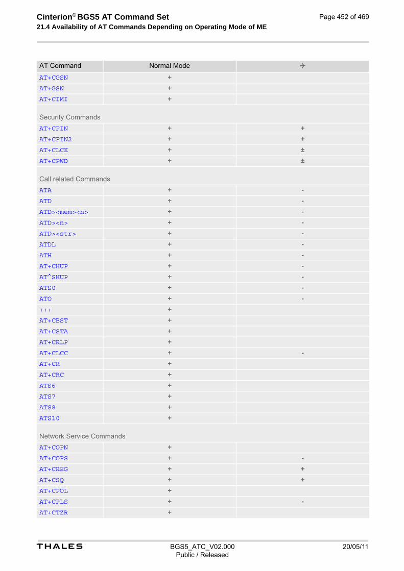
t BGS5_ATC_V02.000 20/05/11Public / Released
Cinterion® BGS5 AT Command Set 21.4 Availability of AT Commands Depending on Operating Mode of ME
Page 452 of 469
AT+CGSN +
AT+GSN +
AT+CIMI +
Security Commands
AT+CPIN + +
AT+CPIN2 + +
AT+CLCK + ±
AT+CPWD + ±
Call related Commands
ATA + -
ATD + -
ATD><mem><n> + -
ATD><n> + -
ATD><str> + -
ATDL + -
ATH + -
AT+CHUP + -
AT^SHUP + -
ATS0 + -
ATO + -
+++ +
AT+CBST +
AT+CSTA +
AT+CRLP +
AT+CLCC + -
AT+CR +
AT+CRC +
ATS6 +
ATS7 +
ATS8 +
ATS10 +
Network Service Commands
AT+COPN +
AT+COPS + -
AT+CREG + +
AT+CSQ + +
AT+CPOL +
AT+CPLS + -
AT+CTZR +
AT Command Normal Mode
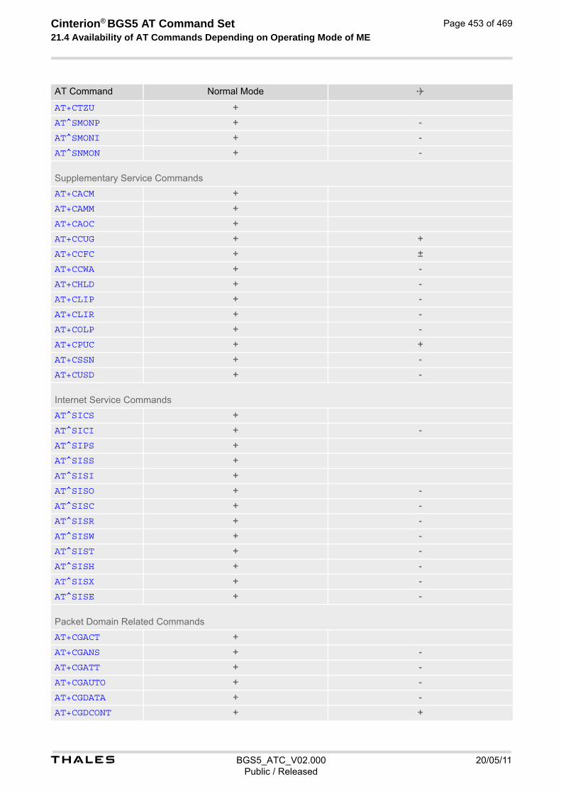
t BGS5_ATC_V02.000 20/05/11Public / Released
Cinterion® BGS5 AT Command Set 21.4 Availability of AT Commands Depending on Operating Mode of ME
Page 453 of 469
AT+CTZU +
AT^SMONP + -
AT^SMONI + -
AT^SNMON + -
Supplementary Service Commands
AT+CACM +
AT+CAMM +
AT+CAOC +
AT+CCUG + +
AT+CCFC + ±
AT+CCWA + -
AT+CHLD + -
AT+CLIP + -
AT+CLIR + -
AT+COLP + -
AT+CPUC + +
AT+CSSN + -
AT+CUSD + -
Internet Service Commands
AT^SICS +
AT^SICI + -
AT^SIPS +
AT^SISS +
AT^SISI +
AT^SISO + -
AT^SISC + -
AT^SISR + -
AT^SISW + -
AT^SIST + -
AT^SISH + -
AT^SISX + -
AT^SISE + -
Packet Domain Related Commands
AT+CGACT +
AT+CGANS + -
AT+CGATT + -
AT+CGAUTO + -
AT+CGDATA + -
AT+CGDCONT + +
AT Command Normal Mode

t BGS5_ATC_V02.000 20/05/11Public / Released
Cinterion® BGS5 AT Command Set 21.4 Availability of AT Commands Depending on Operating Mode of ME
Page 454 of 469
AT+CGCMOD + -
AT+CGEREP + +
AT+CGPADDR + +
AT+CGQMIN + +
AT+CGQREQ + +
AT+CGREG + +
AT+CGSMS + +
ATA + -
ATD*99# + -
AT^SGAUTH + +
AT^SGCONF + +
Short Message Service (SMS) Commands
AT+CMGC + -
AT+CMGD + +
AT+CMGF + +
AT+CMGL + +
AT+CMGR + +
AT+CMGS + -
AT+CMGW + +
AT+CMMS +
AT+CMSS + -
AT+CNMA + -
AT+CNMI + +
AT+CPMS +
AT+CSCA +
AT+CSCB + +
AT+CSDH +
AT+CSMP +
AT+CSMS +
AT^SMGL +
AT^SMGR +
SIM related Commands
AT+CCID +
AT+CRSM +
AT+CSIM +
SIM Application Toolkit (SAT) Commands
AT^SSTA + +
AT+STKPRO + +
AT+STKTR + +
AT Command Normal Mode
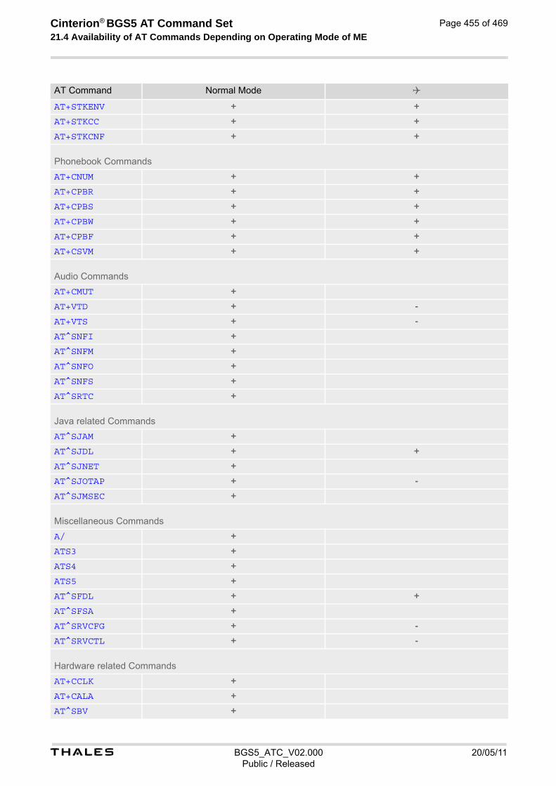
t BGS5_ATC_V02.000 20/05/11Public / Released
Cinterion® BGS5 AT Command Set 21.4 Availability of AT Commands Depending on Operating Mode of ME
Page 455 of 469
AT+STKENV + +
AT+STKCC + +
AT+STKCNF + +
Phonebook Commands
AT+CNUM + +
AT+CPBR + +
AT+CPBS + +
AT+CPBW + +
AT+CPBF + +
AT+CSVM + +
Audio Commands
AT+CMUT +
AT+VTD + -
AT+VTS + -
AT^SNFI +
AT^SNFM +
AT^SNFO +
AT^SNFS +
AT^SRTC +
Java related Commands
AT^SJAM +
AT^SJDL + +
AT^SJNET +
AT^SJOTAP + -
AT^SJMSEC +
Miscellaneous Commands
A/ +
ATS3 +
ATS4 +
ATS5 +
AT^SFDL + +
AT^SFSA +
AT^SRVCFG + -
AT^SRVCTL + -
Hardware related Commands
AT+CCLK +
AT+CALA +
AT^SBV +
AT Command Normal Mode

t BGS5_ATC_V02.000 20/05/11Public / Released
Cinterion® BGS5 AT Command Set 21.4 Availability of AT Commands Depending on Operating Mode of ME
Page 456 of 469
AT^SCTM +
AT^SLED +
AT^SRADC +
AT^SSPI +
AT^SWDAC +
General Purpose I/O (GPIO) Pin related Commands
AT^SCPIN +
AT^SGIO +
AT^SSIO +
AT^SCPOL +
AT^SSCNT +
AT^SCCNT +
AT^SPIO +
AT Command Normal Mode

t BGS5_ATC_V02.000 20/05/11Public / Released
Cinterion® BGS5 AT Command Set 21.5 AT Command Settings storable with AT&W
Page 457 of 469
21.5 AT Command Settings storable with AT&W
Table 21.7: Settings Stored to User Profile
AT Command Stored Parameters
Configuration Commands
ATQ <n>
ATV <value>
ATX <value>
AT+CMEE <errMode>
Serial Interface Control Commands
AT\Q <n>
AT&C <value>
AT&D <value>
AT&S <value>
ATE <value>
AT+ICF <format>, <parity>
Call related Commands
ATS0 <n>
AT+CBST <speed>, <name>, <ce>
AT+CRLP <iws>, <mws>, <T1>, <N2>
AT+CR <mode>
AT+CRC <mode>
ATS6 <n>
ATS7 <n>
ATS8 <n>
ATS10 <n>
Network Service Commands
AT+COPS <format>
AT+CREG <Mode>
Supplementary Service Commands
AT+CLIP <n>
Short Message Service (SMS) Commands
AT+CMGF <mode>
AT+CNMI <mode>, <mt>, <bm>, <ds>, <bfr>
AT+CSDH <show>
AT+CSMS <service>
Miscellaneous Commands
ATS3 <n>
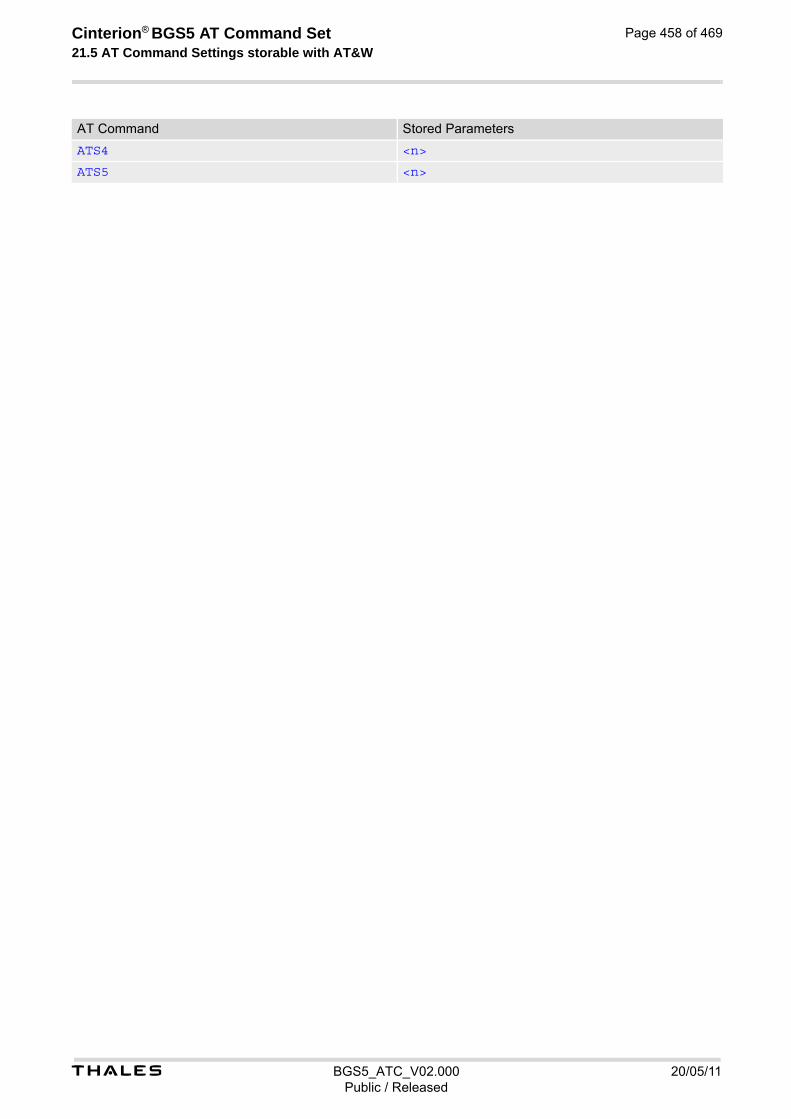
t BGS5_ATC_V02.000 20/05/11Public / Released
Cinterion® BGS5 AT Command Set 21.5 AT Command Settings storable with AT&W
Page 458 of 469
ATS4 <n>
ATS5 <n>
AT Command Stored Parameters
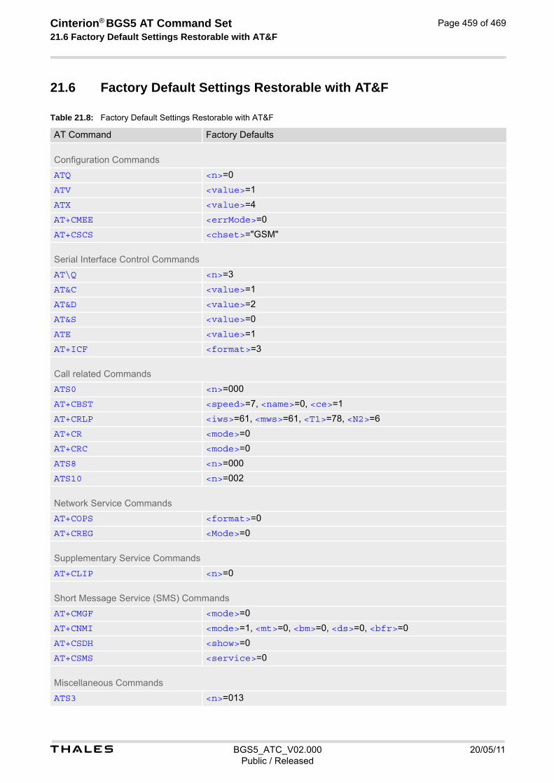
t BGS5_ATC_V02.000 20/05/11Public / Released
Cinterion® BGS5 AT Command Set 21.6 Factory Default Settings Restorable with AT&F
Page 459 of 469
21.6 Factory Default Settings Restorable with AT&F
Table 21.8: Factory Default Settings Restorable with AT&F
AT Command Factory Defaults
Configuration Commands
ATQ <n>=0
ATV <value>=1
ATX <value>=4
AT+CMEE <errMode>=0
AT+CSCS <chset>="GSM"
Serial Interface Control Commands
AT\Q <n>=3
AT&C <value>=1
AT&D <value>=2
AT&S <value>=0
ATE <value>=1
AT+ICF <format>=3
Call related Commands
ATS0 <n>=000
AT+CBST <speed>=7, <name>=0, <ce>=1
AT+CRLP <iws>=61, <mws>=61, <T1>=78, <N2>=6
AT+CR <mode>=0
AT+CRC <mode>=0
ATS8 <n>=000
ATS10 <n>=002
Network Service Commands
AT+COPS <format>=0
AT+CREG <Mode>=0
Supplementary Service Commands
AT+CLIP <n>=0
Short Message Service (SMS) Commands
AT+CMGF <mode>=0
AT+CNMI <mode>=1, <mt>=0, <bm>=0, <ds>=0, <bfr>=0
AT+CSDH <show>=0
AT+CSMS <service>=0
Miscellaneous Commands
ATS3 <n>=013

t BGS5_ATC_V02.000 20/05/11Public / Released
Cinterion® BGS5 AT Command Set 21.6 Factory Default Settings Restorable with AT&F
Page 460 of 469
ATS4 <n>=010
ATS5 <n>=008
AT Command Factory Defaults
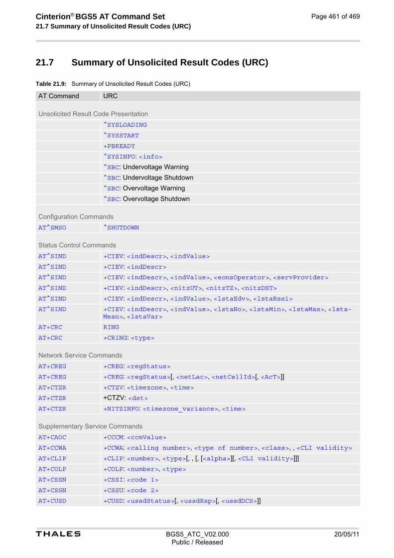
t BGS5_ATC_V02.000 20/05/11Public / Released
Cinterion® BGS5 AT Command Set 21.7 Summary of Unsolicited Result Codes (URC)
Page 461 of 469
21.7 Summary of Unsolicited Result Codes (URC)
Table 21.9: Summary of Unsolicited Result Codes (URC)
AT Command URC
Unsolicited Result Code Presentation
^SYSLOADING
^SYSSTART
+PBREADY
^SYSINFO: <info>
^SBC: Undervoltage Warning
^SBC: Undervoltage Shutdown
^SBC: Overvoltage Warning
^SBC: Overvoltage Shutdown
Configuration Commands
AT^SMSO ^SHUTDOWN
Status Control Commands
AT^SIND +CIEV: <indDescr>, <indValue>
AT^SIND +CIEV: <indDescr>
AT^SIND +CIEV: <indDescr>, <indValue>, <eonsOperator>, <servProvider>
AT^SIND +CIEV: <indDescr>, <nitzUT>, <nitzTZ>, <nitzDST>
AT^SIND +CIEV: <indDescr>, <indValue>, <lstaEdv>, <lstaRssi>
AT^SIND +CIEV: <indDescr>, <indValue>, <lstaNo>, <lstaMin>, <lstaMax>, <lsta-Mean>, <lstaVar>
AT+CRC RING
AT+CRC +CRING: <type>
Network Service Commands
AT+CREG +CREG: <regStatus>
AT+CREG +CREG: <regStatus>[, <netLac>, <netCellId>[, <AcT>]]
AT+CTZR +CTZV: <timezone>, <time>
AT+CTZR +CTZV: <dst>
AT+CTZR +NITZINFO: <timezone_variance>, <time>
Supplementary Service Commands
AT+CAOC +CCCM: <ccmValue>
AT+CCWA +CCWA: <calling number>, <type of number>, <class>, , <CLI validity>
AT+CLIP +CLIP: <number>, <type>[, , [, [<alpha>][, <CLI validity>]]]
AT+COLP +COLP: <number>, <type>
AT+CSSN +CSSI: <code 1>
AT+CSSN +CSSU: <code 2>
AT+CUSD +CUSD: <ussdStatus>[, <ussdRsp>[, <ussdDCS>]]

t BGS5_ATC_V02.000 20/05/11Public / Released
Cinterion® BGS5 AT Command Set 21.7 Summary of Unsolicited Result Codes (URC)
Page 462 of 469
Internet Service Commands
AT^SISR ^SISR: <srvProfileId>, <urcCauseId>
AT^SISW ^SISW: <srvProfileId>, <urcCauseId>
Internet Ser-vice URC "^SIS"
^SIS: <srvProfileId>, <urcCause>[, [<urcInfoId>][, <urcInfoText>]]
Packet Domain Related Commands
AT+CGEREP +CGEV: NW DEACT <PDP_type>, <PDP_addr>[, <cid>]
AT+CGEREP +CGEV: ME DEACT <PDP_type>, <PDP_addr>[, <cid>]
AT+CGEREP +CGEV: NW DETACH
AT+CGEREP +CGEV: ME DETACH
AT+CGREG +CGREG: <stat>
AT+CGREG +CGREG: <stat>[, <lac>, <ci>]
Short Message Service (SMS) Commands
AT+CNMI +CMTI: <mem3>, <index>
AT+CNMI +CMT: [<alpha>], <length><CR><LF><pdu>
AT+CNMI +CMT: <oa>, [<alpha>], <scts>[, <tooa>, <fo>, <pid>, <dcs>, <sca>, <tosca>, <length>]<CR><LF><data>
AT+CNMI +CBM: <length><CR><LF><pdu>
AT+CNMI +CBM: <sn>, <mid>, <dcs>, <page>, <pages><CR><LF><data>
AT+CNMI +CBMI: <mem3>, <index>
AT+CNMI +CDS: <length><CR><LF><pdu>
AT+CNMI +CDS: <fo>, <mr>[, <ra>][, <tora>], <scts>, <dt>, <st>
AT+CNMI +CDSI: <mem3>, <index>
SIM Application Toolkit (SAT) Commands
AT+STKPRO +STKPRO: 01, <CmdQualifier>
AT+STKPRO +STKPRO: 05, <EventList>
AT+STKPRO +STKPRO: 16, <DialNumber>, <Subaddr>, <CmdQualifier>, <Alpha1>, <IconId1>, <Alpha2>, <IconId2>
AT+STKPRO +STKPRO: 17, <SsData>, <Alpha>, <IconId>, <RefNumber>
AT+STKPRO +STKPRO: 18, <Dcs>, <HexString>, <Alpha>, <IconId>, <RefNumber>
AT+STKPRO +STKPRO: 19, <Alpha>, <IconId>, <RefNumber>
AT+STKPRO +STKPRO: 20, <Alpha>, <IconId>, <DtmfStr>
AT+STKPRO +STKPRO: 21, <Url>, <Alpha>, <IconId>
AT+STKPRO +STKPRO: 32, <Tone>, <TimeUnit>, <Interval>, <Alpha>, <IconId>
AT+STKPRO +STKPRO: 33, <CmdQualifier>, <Dcs>, <HexString>, <IconId>
AT+STKPRO +STKPRO: 34, <CmdQualifier>, <Dcs>, <HexString>, <IconId>
AT+STKPRO +STKPRO: 35, <CmdQualifier>, <Dcs>, <HexString>, <MaxRespLen>, <MinRe-spLen>, <DefaultText>, <IconId>
AT+STKPRO +STKPRO: 36, <CmdQualifier>, <Alpha>, <ItemId>, <TotalItems>, <Item-Text>, <NextAction>, <DefaultItem>, <IconId>, <IconIdListElem>
AT Command URC

t BGS5_ATC_V02.000 20/05/11Public / Released
Cinterion® BGS5 AT Command Set 21.7 Summary of Unsolicited Result Codes (URC)
Page 463 of 469
AT+STKPRO +STKPRO: 37, <CmdQualifier>, <Alpha>, <ItemId>, <TotalItems>, <Item-Text>, <NextAction>, <IconId>, <IconIdListElem>
AT+STKPRO +STKPRO: 38, <CmdQualifier>
AT+STKPRO +STKPRO: 40, <Dcs>, <HexString>, <IconId>
AT+STKPRO +STKPRO: 53, <Lang>
AT+STKPRO +STKPRO: 64, <CmdQualifier>, <Alpha>, <IconId>, <DialNumber>, <ReconIn-terval>, <ReconTimeUnit>, <IdleInterval>, <IdleUnit>, <BearerType>, <BearerParam>, <BufSize>, <LoginDcs>, <LoginText>, <PasswordDcs>, <PasswordText>, <TransportLevel>, <TransportPort>, <SubaddrCs>, <DestAddrType>, <DestAddr>
AT+STKPRO +STKPRO: 65, <CmdQualifier>, <Alpha>, <IconId>
AT+STKPRO +STKPRO: 66, <CmdQualifier>, <Alpha>, <IconId>, <ChannelID>, <Channel-DataLen>
AT+STKPRO +STKPRO: 67, <CmdQualifier>, <Alpha>, <IconId>, <ChannelID>, <Channel-Data>
AT+STKPRO +STKPRO: 68, <CmdQualifier>
AT+STKCC +STKCC: 1, <ResVal>, <Alpha>, <PhoneNumber>, <NumberType>
AT+STKCC +STKCC: 2, <ResVal>, <Alpha>, <SsCode>
AT+STKCC +STKCC: 3, <ResVal>, <Alpha>, <UssdCode>
AT+STKCC +STKCC: 4, <ResVal>, <Alpha>, <ToSca>, <Sca>, <ToRa>, <Ra>
AT+STKCNF +STKCNF: <ProactCmd>, <Result>, <AddResult>, <Sw1>
Miscellaneous Commands
AT^SRVCTL In case of success: ^SRVCTL: "CBL" , "Loc" , <CBLCode>, <CBLLatitude>, <CBLLongitude>, <CBLAc-curacy>[, <CBLCountryCode>, <CBLCountry>, <CBLCity>] OKIn case of error: ^SRVCTL: "CBL" , "Loc" , <CBLCode>, <CBLMessage> ERROR+CME ERROR: <err>
Hardware related Commands
AT+CALA +CALA: [<text>]
AT^SCTM ^SCTM_B: <UrcCause>
AT^SCTM ^SHUTDOWN
AT^SRADC ^SRADC: <count>, <value>[, <value>[, <value>[, <value>[, <value>[, <value>[, <value>[, <value>[, <value>[, <value>[, <value>]]]]]]]]]]
General Purpose I/O (GPIO) Pin related Commands
AT^SCPOL ^SCPOL: <io_id>, <value>
AT^SSCNT ^SSCNT: <pulse>
AT^SCCNT ^SCCNT: <time>
AT Command URC

t BGS5_ATC_V02.000 20/05/11Public / Released
Cinterion® BGS5 AT Command Set 21.8 Alphabetical List of AT Commands
Page 464 of 469
21.8 Alphabetical List of AT Commands
Table 21.10: Alphabetical List of AT Commands
AT Command Description Section and Page
+++ Switch from data mode or PPP online mode to command mode
Section 7.12, page 131
A/ Repeat Previous Command Line Section 18.1, page 378
AT&C Set Data Carrier Detect (DCD) Line Mode Section 4.2, page 90
AT&D Set Data Terminal Ready (DTR) Line Mode Section 4.3, page 91
AT&F Reset AT Command Settings to Factory Default Values Section 2.1, page 31
AT&S Set Data Set Ready (DSR) Line Mode Section 4.4, page 92
AT&V Display current configuration Section 2.2, page 32
AT&W Store AT Command Settings to User Defined Profile Section 2.3, page 34
AT+CACM Accumulated call meter (ACM) reset or query Section 9.1, page 165
AT+CALA Alarm Configuration Section 19.2, page 408
AT+CAMM Accumulated call meter maximum (ACMmax) set or query Section 9.2, page 166
AT+CAOC Advice of Charge Information Section 9.3, page 167
AT+CBST Select Bearer Service Type Section 7.13, page 132
AT+CCFC Call forwarding number and conditions control Section 9.5, page 170
AT+CCID SIM Card Identification Number Section 13.1, page 312
AT+CCLK Real Time Clock Section 19.1, page 407
AT+CCUG Closed User Group Section 9.4, page 168
AT+CCWA Call Waiting Section 9.6, page 173
AT+CEER Extended Error Report Section 3.1, page 73
AT+CFUN Functionality Level Section 2.8, page 39
AT+CGACT PDP context activate or deactivate Section 11.1, page 248
AT+CGANS Manual response to a network request for PDP context activation
Section 11.2, page 250
AT+CGATT PS attach or detach Section 11.3, page 252
AT+CGAUTO Automatic response to Network Request for PDP Context Activation
Section 11.4, page 253
AT+CGCMOD PDP Context Modify Section 11.7, page 259
AT+CGDATA Enter data state Section 11.5, page 255
AT+CGDCONT Define PDP Context Section 11.6, page 257
AT+CGEREP Packet Domain Event Reporting Section 11.8, page 260
AT+CGMI Request manufacturer identification Section 5.2, page 101
AT+CGMM Request model identification Section 5.3, page 102
AT+CGMR Request revision identification of software status Section 5.4, page 103
AT+CGPADDR Show PDP address Section 11.9, page 262
AT+CGQMIN Quality of Service Profile (Minimum acceptable) Section 11.10, page 263
AT+CGQREQ Quality of Service Profile (Requested) Section 11.11, page 267
AT+CGREG Packet Domain Network Registration Status Section 11.12, page 271
AT+CGSMS Select Service for MO Short messages Section 11.13, page 273
AT+CGSN Request International Mobile Equipment Identity (IMEI) Section 5.5, page 104

t BGS5_ATC_V02.000 20/05/11Public / Released
Cinterion® BGS5 AT Command Set 21.8 Alphabetical List of AT Commands
Page 465 of 469
AT+CHLD Call Hold and Multiparty Section 9.7, page 176
AT+CHUP Hang up call Section 7.8, page 127
AT+CIMI Request International Mobile Subscriber Identity (IMSI) Section 5.7, page 106
AT+CLCC List of current calls Section 7.16, page 136
AT+CLCK Facility lock Section 6.3, page 111
AT+CLIP Calling Line Identification Presentation Section 9.8, page 178
AT+CLIR Calling Line Identification Restriction Section 9.9, page 180
AT+CMEE Error Message Format Section 2.10, page 42
AT+CMGC Send SMS Command Section 12.2, page 283
AT+CMGD Delete short message Section 12.3, page 284
AT+CMGF Select SMS message format Section 12.4, page 285
AT+CMGL List SMS messages from preferred store Section 12.5, page 286
AT+CMGR Read SMS messages Section 12.6, page 288
AT+CMGS Send SMS Section 12.7, page 290
AT+CMGW Write Short Messages to Memory Section 12.8, page 292
AT+CMMS More Messages to Send Section 12.9, page 294
AT+CMSS Send short messages from storage Section 12.10, page 295
AT+CMUT Mute control Section 16.1, page 354
AT+CMUX Multiplex mode Section 4.7, page 96
AT+CNMA New Message Acknowledgement to ME/TE Section 12.11, page 296
AT+CNMI SMS Event Reporting Configuration Section 12.12, page 298
AT+CNUM Read own numbers Section 15.1, page 342
AT+COLP Connected Line Identification Presentation Section 9.10, page 181
AT+COPN Read operator names Section 8.1, page 145
AT+COPS Operator Selection Section 8.2, page 146
AT+CPAS Activity Status Section 3.3, page 88
AT+CPBF Find phonebook entries Section 15.5, page 350
AT+CPBR Read from Phonebook Section 15.2, page 343
AT+CPBS Select phonebook memory storage Section 15.3, page 346
AT+CPBW Write into Phonebook Section 15.4, page 348
AT+CPIN PIN Authentication Section 6.1, page 107
AT+CPIN2 PIN2 Authentication Section 6.2, page 109
AT+CPLS Select Preferred Operator List Section 8.6, page 154
AT+CPMS Preferred SMS message storage Section 12.13, page 301
AT+CPOL Preferred Operator List Section 8.5, page 152
AT+CPUC Price per unit and currency table Section 9.11, page 183
AT+CPWD Change Password Section 6.4, page 115
AT+CR Service reporting control Section 7.17, page 138
AT+CRC Incoming Call Indication Format Section 7.18, page 139
AT+CREG Network Registration Status Section 8.3, page 149
AT+CRLP Configure RLP Parameters for Outgoing Non-Transparent Data Calls
Section 7.15, page 135
AT Command Description Section and Page

t BGS5_ATC_V02.000 20/05/11Public / Released
Cinterion® BGS5 AT Command Set 21.8 Alphabetical List of AT Commands
Page 466 of 469
AT+CRSM Restricted SIM Access Section 13.2, page 313
AT+CSCA SMS Service Center Address Section 12.14, page 303
AT+CSCB Select Cell Broadcast Message Indication Section 12.15, page 304
AT+CSCS Character Set Section 2.11, page 51
AT+CSDH Show SMS text mode parameters Section 12.16, page 305
AT+CSIM Generic SIM Access Section 13.3, page 315
AT+CSMP Set SMS Text Mode Parameters Section 12.17, page 306
AT+CSMS Select Message Service Section 12.18, page 308
AT+CSQ Signal quality Section 8.4, page 151
AT+CSSN Supplementary service notifications Section 9.12, page 185
AT+CSTA Select type of address Section 7.14, page 134
AT+CSVM Set voice mail number Section 15.6, page 352
AT+CTZR Time Zone Reporting Section 8.7, page 155
AT+CTZU Automatic Time Zone Update Section 8.8, page 157
AT+CUSD Unstructured Supplementary Service Data Section 9.13, page 187
AT+GSN Request International Mobile Equipment Identity (IMEI) Section 5.6, page 105
AT+ICF Character Framing Section 4.8, page 98
AT+IPR Bit Rate Section 4.6, page 94
AT+STKCC SAT Call Control Notification Section 14.5, page 336
AT+STKCNF SAT Proactive Session Status Section 14.6, page 338
AT+STKENV SAT Envelope Command Section 14.4, page 334
AT+STKPRO SAT Proactive Command URCs Section 14.2, page 320
AT+STKTR SAT Terminal Response Commands Section 14.3, page 328
AT+VTD Tone duration Section 16.2, page 355
AT+VTS DTMF and tone generation Section 16.3, page 356
AT\Q Flow Control Section 4.1, page 89
AT^SBV Battery/Supply Voltage Section 19.3, page 411
AT^SCCNT Configure Pulse Counter Section 20.6, page 438
AT^SCFG Extended Configuration Settings Section 2.12, page 52
AT^SCPIN Pin Configuration Section 20.1, page 430
AT^SCPOL Polling Configuration Section 20.4, page 435
AT^SCTM Critical Operating Temperature Monitoring Section 19.4, page 412
AT^SFDL Firmware Download Section 18.5, page 382
AT^SFSA Flash File System Access Section 18.6, page 383
AT^SGAUTH Set Type of Authentication for PDP-IP Connections Section 11.16, page 276
AT^SGCONF Configurable GPRS Multislot Class Section 11.17, page 278
AT^SGIO Get IO State of a Specified Pin Section 20.2, page 433
AT^SHUP Hang up call(s) indicating a specific 3GPP TS 24.008 release cause
Section 7.9, page 128
AT^SICI Internet Connection Information Section 10.2, page 196
AT^SICS Internet Connection Setup Profile Section 10.1, page 193
AT^SIND Extended Indicator Control Section 3.2, page 81
AT Command Description Section and Page

t BGS5_ATC_V02.000 20/05/11Public / Released
Cinterion® BGS5 AT Command Set 21.8 Alphabetical List of AT Commands
Page 467 of 469
AT^SIPS Internet Profile Storage Section 10.3, page 199
AT^SISC Internet Service Close Section 10.7, page 214
AT^SISE Internet Service Error Report Section 10.13, page 226
AT^SISH Disconnect Remote Client Section 10.11, page 223
AT^SISI Internet Service Information Section 10.5, page 208
AT^SISO Internet Service Open Section 10.6, page 210
AT^SISR Internet Service Read Data Section 10.8, page 215
AT^SISS Internet Service Setup Profile Section 10.4, page 200
AT^SIST Enter Transparent Mode Section 10.10, page 221
AT^SISW Internet Service Write Data Section 10.9, page 218
AT^SISX Internet Service Execution Section 10.12, page 224
AT^SJAM Manage Java Application Section 17.1, page 365
AT^SJDL Java Download Section 17.2, page 368
AT^SJMSEC Java Midlet Security Section 17.5, page 375
AT^SJNET Set Dialup Network Access Parameters Section 17.3, page 370
AT^SJOTAP Over The Air Application Provisioning Section 17.4, page 372
AT^SLED LED Feature Section 19.5, page 414
AT^SMGL List Short Messages from preferred store without setting status to REC READ
Section 12.19, page 310
AT^SMGR Read short message without setting status to REC READ Section 12.20, page 311
AT^SMONI Display Server Cell Information Section 8.10, page 160
AT^SMONP Display Neighbor Cell Information Section 8.9, page 158
AT^SMSO Switch Off BGS5 Section 2.9, page 41
AT^SNFI Set microphone path parameters Section 16.4, page 358
AT^SNFM Set microphone audio path and power supply Section 16.5, page 359
AT^SNFO Set audio output (= loudspeaker path) parameter Section 16.6, page 360
AT^SNFS Select audio hardware set Section 16.7, page 361
AT^SNMON Network Monitoring Section 8.11, page 163
AT^SPIO GPIO Driver Open/Close Section 20.7, page 440
AT^SPOW Set UART Mode and SLEEP Mode on UART Section 2.13, page 71
AT^SRADC Configure and Read ADC Measurement Section 19.6, page 416
AT^SRTC Ring tone configuration Section 16.8, page 363
AT^SRVCFG Service Configuration Settings Section 18.7, page 393
AT^SRVCTL Extra Service Control Section 18.8, page 402
AT^SSCNT Start and Stop Pulse Counter Section 20.5, page 436
AT^SSIO Set IO State of a Specified Pin Section 20.3, page 434
AT^SSPI Serial Protocol Interface Section 19.7, page 419
AT^SSTA Remote-SAT Interface Activation Section 14.1, page 317
AT^SWDAC PWM Signal Configuration for DAC Section 19.8, page 428
ATA Connect to Incoming Call Section 7.1, page 118
ATA Manual Acceptance of a Network Request for PDP Con-text Activation
Section 11.14, page 274
AT Command Description Section and Page

t BGS5_ATC_V02.000 20/05/11Public / Released
Cinterion® BGS5 AT Command Set 21.8 Alphabetical List of AT Commands
Page 468 of 469
ATD Mobile originated call to specified number Section 7.2, page 119
ATD*99# Request Packet Domain Service Section 11.15, page 275
ATD><mem><n> Mobile originated call using specific memory and index number
Section 7.3, page 121
ATD><n> Mobile originated call from active memory using index number
Section 7.4, page 123
ATD><str> Mobile originated call from active memory using corre-sponding field
Section 7.5, page 124
ATDL Redial last number used Section 7.6, page 125
ATE AT Command Echo Section 4.5, page 93
ATH Disconnect existing connection Section 7.7, page 126
ATI Display product identification information Section 5.1, page 100
ATO Switch from command mode to data mode / PPP online mode
Section 7.11, page 130
ATQ Result Code Presentation Mode Section 2.4, page 35
ATS0 Set number of rings before automatically answering a call Section 7.10, page 129
ATS10 Set disconnect delay after indicating the absence of data carrier
Section 7.22, page 144
ATS3 Command Line Termination Section 18.2, page 379
ATS4 Response Formatting Section 18.3, page 380
ATS5 Command Line Editing Section 18.4, page 381
ATS6 Set pause before blind dialing Section 7.19, page 141
ATS7 Set number of seconds to wait for connection completion Section 7.20, page 142
ATS8 Comma Dial Pause Time Section 7.21, page 143
ATV Result code format mode Section 2.5, page 36
ATX CONNECT Result Code Format Section 2.6, page 37
ATZ Restore AT Command Settings from User Defined Profile Section 2.7, page 38
AT Command Description Section and Page
469
THALES DIS AIS Deutschland GmbHWerinherstrasse 8181541 MunichGermany
© T
halle
s 2
020
. All
righ
ts r
ese
rve
d. T
hale
s, t
he
Th
ale
s lo
go
, are
tra
dem
ark
s a
nd s
erv
ice
ma
rks
of T
hale
s an
d a
re r
egis
tere
d in
cer
tain
cou
ntri
es.


