BHARAT HEAVY ELECTRICALS LIMITED TRANSMISSION BUSINESS GROUP (ENGINEERING MANAGEMENT) LODHI ROAD NEW DELHI TENDER DOCUMENTS FOR TENDER FOR CONSULTANCY WORK FOR ILLUMINATION SYSTEM DESIGN INCLUDING PREPARATION OF DESIGNS, DRAWINGS & BOM OF ILLUMINATION PACKAGE ITEMS FOR 400/220kV SWITCHYARD EXTENSION AT BELLARY – III AND 400kV SWITCHYARD AT YERAMARUS TENDER SPEC. NO.: TBEM/ILLUM_DESIGN/CONSULTANCY/TENDER DATED: 05.10.2013
Transcript
BHARAT HEAVY ELECTRICALS LIMITED TRANSMISSION BUSINESS GROUP
(ENGINEERING MANAGEMENT) LODHI ROAD NEW DELHI
TENDER DOCUMENTS
FOR
TENDER FOR CONSULTANCY WORK FOR ILLUMINATION SYSTEM
DESIGN INCLUDING PREPARATION OF DESIGNS, DRAWINGS & BOM OF ILLUMINATION PACKAGE ITEMS FOR
400/220kV SWITCHYARD EXTENSION AT BELLARY – III AND 400kV SWITCHYARD AT YERAMARUS
SUB: TENDER FOR CONSULTANCY WORK FOR ILLUMINATION SYSTEM DESIGN
INCLUDING PREPARATION OF DESIGNS, DRAWINGS & BOM OF ILLUMINATION PACKAGE ITEMS FOR 400/220kV SWITCHYARD EXTENSION AT BELLARY – III AND 400kV SWITCHYARD AT YERAMARUS
Dear Sirs,
1. Sealed tenders are invited for the following works:
NAME OF WORK
TIME OF
COMPLETION
EARNEST MONEY
DEPOSIT
TENDER SUBMISSION
DATE AND TIME
TENDER OPENING DATE
& TIME
Consultancy work for Illumination system and Electrical system Design including preparation of designs, drawings & BOM of illumination package items for 400/220kV Switchyard extension at Bellary –III and 400kV Switchyard at Yeramarus
Refer clause no. 6.0.0 “Time schedule” Specification for Consultancy’ enclosed with NIT.
Rs.10,000 (in form of DD or Pay Order)
30.10.13 15.00 hrs.
30.10.13
15.30 hrs. (Technical bid
only) and
Date of opening
of Price bid Shall be
informed to tenderer subject
to techno commercial
acceptance of offer.
2. ADDRESS FOR SUBMISSION AND OPENING OF TENDER:
BHARAT HEAVY ELECTRICALS LIMITED, TRANSMISSION BUSINESS GROUP, LODHI ROAD NEW DELHI, ATTN: BALAJI AIYER, Dy. MANAGER (TBEM) Phone: 01141793477, Fax: 011-24369509 e-mail: [email protected]
Regd. Office: BHEL House, Siri Fort, New Delhi - 110049
3. The prospective bidders who have downloaded the tender documents are requested to send their acknowledgement and willingness to participate in the tender to the undersigned, through fax or email.
4. Offers should be strictly in accordance with the Tender Specifications and General
Instructions to Tenderer enclosed herewith. 5. BHEL reserves the right to go for a Reverse Auction instead of Opening the submitted
sealed bid, which will be decided after technical evaluation. As such, the bidders should submit their best prices in the ‘Sealed Price Bid’. However, bidders are required to confirm their acceptance of “General terms and conditions” governing RA specifically in their technical bid. The “General terms and conditions” governing RA are given below in the NIT. Bidders are also required to furnish following details in their techno-commercial bid, for this purpose (RA).
Authorization of representative who will participate in the on line Reverse auction Process;
a. Name and Designation of official b. Postal Address (Complete) c. Telephone Nos. (Land line & Mobile both) d. FAX No. e. E-mail address f. Name of Place/ State/ Country, wherefrom he will participate in the RA.
6. Clarifications, if any, can be obtained from the undersigned but such requests should be submitted well before the due date for submission of tenders. Due date for submission and opening of tenders will not be extended on such grounds.
7. Technical Bid will be opened in the office of undersigned. If required, technical
discussions will be held with only those bidders who have taken any deviations. Bidders representative may be present during technical bid opening for technical discussion, if required. The price bids will be opened subsequently, after Technical Bids of all the Tenderers which have been evaluated and freezed. Bidders should quote their most competitive rates as there will not be any price negotiation. However if felt necessary by BHEL, price negotiation will be held with lowest bidder (L-1) only. IT WOULD BE PREFERRED THAT YOUR OFFER IS WITHOUT ANY DEVIATION w.r.t. TENDER SPECIFICATIONS AND THE SAME MAY BE CLEARLY MENTIONED ON THE COVERING LETTER ACCOMPANYING THE TECHNICAL BID. Offers with deviations are likely to be rejected. However if the bidder insists on any technical or commercial deviations, from the specification and/or tender conditions, the price implication if any, of withdrawing the deviations must be submitted along with the price bid in a separate sealed envelope superscribed “Price Implication for withdrawal of deviations”.
8. Offers will be scrutinized based on the qualifying requirements and only those who are technically and financially capable to execute the Job and who fulfil the Pre-Qualifying Requirements (PQR) are eligible to quote against the above NIT.
9. In case any adverse information is received concerning performance, capability or conduct of the bidder after issue of tender enquiry, BHEL reserves the right to reject the offer at any stage as deemed fit.
10. The purchase preference for central P.S.Us shall be given as per the prevailing Government policy.
Regd. Office: BHEL House, Siri Fort, New Delhi - 110049
11. In case an offer is not being submitted by the prospective bidders against this tender, they may send their “regret” letter to this office, for information.
12. Details of qualifying work(s) executed by the bidder will be forwarded to the principal
employer for verification of the work with respect to completion, commencement & completion date and value of the work executed. Performance feedback of the bidder may also be sought from the principal employer.
13. The bidder representative may be called for discussion with the committee. His originals may be verified by the committee. In addition to above their organisation chart and detail list of manpower, tools & plants and technically capability will be discussed and ascertained by the committee.
Thanking you, Yours faithfully, for and on Behalf of BHEL, (Balaji Aiyer)
Dy. Manager (TBEM)
TO BE FILLED BY TENDERER Certified that General Instructions and Information for tenderer have been read/complied/ agreed to and each page of tender offer has been initialled and stamped. (Signature & Seal of Tenderer) Name and Designation of Authorised person (s) Signing the tender on behalf of the tenderer
Regd. Office: BHEL House, Siri Fort, New Delhi - 110049
GENERAL TERMS AND CONDITIONS OF REVERSE AUCTION (RA)
Against this enquiry for the subject item / work with detailed scope as per our tender specification, BHEL – TBG, New Delhi may resort to “REVERSE AUCTION PROCEDURE” i.e. ONLINE BIDDING on INTERNET
1. For the proposed reverse auction, technically and commercially acceptable bidders only shall be eligible to participate.
2. BHEL will engage the services of a service provider who will provide all necessary training and assistance before commencement of on line bidding on Internet.
3. In case BHEL decides to conduct reverse auction, BHEL’s service provider shall
contact the vendor directly and impart them the training.
4. Business rules like event date, time, start price, bid decrement, extensions, etc. also will be communicated through service provider for compliance.
5. Vendors have to fax the compliance from in the prescribed (provided by service
provider) before start of Reverse auction. Without this the vendor will not be eligible to participate in the event.
6. Total Price quoted shall be in line with the NIT conditions for the subject work in
Indian Rupees (INR), which is to be worked out as per the BOQ (Rate Schedule) given in tender enquiry and subsequent changes made, if any. EXCEL Sheet shall be provided, if applicable.
7. Reverse auction will be conducted on schedule date & time.
8. At the end of reverse auction event, the lowest bidder value will be known on the
network.
9. The Lowest bidder has to fax the duly signed filled-in prescribed format as provided on case-to-case basis to BHEL through service provider within 24 hours of auction without fail.
10. Any variation between the on-line bid value and signed document will be considered as sabotaging the tender process and will invite disqualification of vender to conduct business with BHEL as per prevailing procedure.
11. In case BHEL decides not to go for Reverse auction procedure for this tender enquiry, the price bids and price impacts, if any already submitted and available with BHEL shall be opened as per BHEL standard practice.
Regd. Office: BHEL House, Siri Fort, New Delhi - 110049
Authorization of representative who will participate in the on line Reverse Auction Process:
1 NAME & DESIGNATION OF OFFICIAL
2 POSTAL ADDRESS (COMPLETE)
3 TELEPHONE NOS. (LAND LINE & MOBILE BOTH)
4 FAX NO.
5 E-MAIL ADDRESS
6 NAME OF PLACE / STATE / COUNTRY, WHEREFROM S/HE WILL PARTICIPATE IN THE REVERSE AUCTION
Page 1 of 2
BHARAT HEAVY ELECTRICALS LIMITED TRANSMISSION BUSINESS GROUP, NEW DELHI
Name of Work: Tender for Consultancy work for Illumination System Design including preparation of designs, drawings & BOM of illumination package items for 400/220kV Switchyard extension at Bellary – III and 400kV Switchyard at Yeramarus.
Sealed Tenders (Under two part bid system) are invited for above work. Only those who are technically and financially capable to execute the Job and who fulfill the Pre-Qualifying Requirements [PQR] given under are eligible to quote against the above NIT. Tenderers should submit their offer in a sealed envelope as per the procedure specified in tender documents. The PQR of contractor for tender submission shall be as per following prerequisites:
FINANCIAL
1. Bidder should have a minimum average annual turnover of. Rs.1.5 Lakhs and should submit audited balance sheet and Profit & Loss Account for last three years (2010-11, 2011-12 & 2012-13). In case audited balance sheet is not available due to turnover being less than statutory requirement of audit, bidder should furnish self certified copies of Balance Sheet, Profit & Loss account along with income tax returns of these years.
2. Bidder should have successfully executed similar (refer note a, b & c below) job during last seven years ending 30.09.13. Bidder should produce certification/proof in support of execution of similar package from user/end user and should be either of the following:
One similar work executed costing not less than Rs. 1.8 Lakhs
OR
Two similar works executed costing not less than Rs. 1.1 Lakhs each OR
Three similar works executed costing not less than Rs. 0.8 Lakhs each
3. Bidder should have earned profit in at least one year during last three financial years (2010-11, 2011-12 & 2012-13)
Notes:
a) Similar Works: Similar works shall mean successfully executed consultancy works of design of Illumination package for 132kV or above rating switchyards or Power Plants of Powergrid/NTPC/NHPC or other SEBs etc.
b) Cost of similar works as required in financial criteria shall mean executed order value of design work for Illumination package of Switchyards / Power Plants. (as mentioned in Sl. No. 3 of tech. PQR).
c) The word ‘executed’ means the bidder should have achieved the criteria specified above
even if the total contract has not been completed or closed.
Page 2 of 2
TECHNICAL
1. Bidder should be a Design Consultant with minimum experience of 2 years as on
30.09.13, of in-house design capability in designing of Illumination Systems for Outdoor Switchyards or Power Plants and Control Room Buildings.
2. Bidder should have designed Illumination System for at least 1 project of 132kV or higher
kV switchyards or Power Plants of Powergrid / NTPC/NHPC or other SEBs etc. and approved drawings and design documents shall be available with the bidder.
3. Bidder should have done projects of Illumination packages of Switchyards / Power Plants
owned by Powergrid /NTPC/NHPC/SEB etc. either directly or through some third party EPC contractor.
Relevant documents (like order copies /completion certificates for projects) of bidders should be submitted with the bid. BHEL reserves the right to verify the approved design and drawings at Contract stage.
Important Notes
1) BHEL reserves the right to: (a) Accept or reject any bid received at its discretion without assigning any reasons
whatsoever.
(b) Postpone the above mentioned date, split and distribute the work among more than one bidder without assigning any reason whatsoever.
(c) May ask for further qualification during techno commercial scrutiny of bids received.
2) BHEL shall not be responsible for any delay, loss, damage for bids sent by post.
3) BHEL shall not be liable for any expenses incurred by bidder in preparation of bid irrespective of whether it is accepted or not.
4) Quotations received from bidders who do not fulfil the PQR shall be summarily rejected without any further evaluation and information to bidders.
5) Canvassing i.e. soliciting favour, seeking advantage etc. in any form is strictly prohibited and any bidder found to have engaged in canvassing shall be liable to have his bid rejected summarily.
6) If the bidder deliberately gives any wrong information in his tender to create in circumstances
for the acceptance to his bid, BHEL reserves the right to reject such application.
7) All corrigenda, addenda, amendments and clarifications to this Tender will be hosted in web page, www.bhel.com and not in the newspaper. Bidders shall keep themselves updated with all such amendments.
PROCEDURE FOR SUBMISSION OF SEALED TENDERS AND
DOCUMENT TO BE ENCLOSED WITH THE OFFER
The tenderer must submit their tenders as required in two parts in separate sealed covers prominently superscribed as Part-I, Technical Bid Part-II, Price bid and also indicating on each of the covers the tender specification number and due date and time as mentioned in the tender enquiry.
These two separate covers I and II (Part – I and Part-II) shall together be enclosed in third envelope (Cover-III) along with EMD and this sealed cover shall be superscribed and submitted.
PART-I (TECHNICAL BID) COVER-I:
The following documents shall be kept in technical bid envelope:
1) Your covering letter for submission of offer.
2) EMD in the form of DD for the amount as mentioned in NIT.
3) Complete set of tender documents duly signed on each page including unpriced
„BOQ cum price schedule‟, as your acceptance of the tender conditions & NIT in
toto.
4) Documents related to credentials as mentioned below under “important note”
PART-II (PRICE BID) COVER – II :
Rate / Price schedule only shall be given in this part-II "Price Bid" envelope. The price bid of different works (Package/Annexure wise), if applicable, shall be kept in separate envelope duly sealed and super scribed name of the particular price schedule.
IMPORTANT NOTE
Following documents as already specified in the tender terms & conditions must be enclosed along with other documents in technical bid envelope.
1) PAN & Copy of IT returns filed with IT authority (letter).
2) Copy of service tax registration certificate
3) List & Details of similar works executed and under execution.
4) List of available Technical Manpower
5) Audited Balance sheets for last three years.
Offers without the above documents are liable to be rejected as "Techno Commercially Non Complying Offers:
Page 01 of 01
PROJECT INFORMATION
1.0 PROJECT LOCATION AND DETAILS:
As given in the Technical Specification document No.
TB-ILLU_DES-316-111, Rev R0 attached with the NIT 2.0 CONTACT PERSON :FOR CONTRACTUAL & ENGINEERING ISSUES
VIVEK KAPIL Senior Manager (TBEM) TRANSMISSION BUSINESS GROUP, BHEL INDUSTRY SECTOR, IOC, LODHI ROAD, NEW DELHI-03 PHONE: 011- 41793414 FAX : 011- 24369509 e-mail : [email protected] BALAJI AIYER Deputy Manager (TBEM) TRANSMISSION BUSINESS GROUP, BHEL INDUSTRY SECTOR, IOC, LODHI ROAD, NEW DELHI-03 PHONE: 011- 41793477 FAX : 011- 24369509 e-mail : [email protected]
Page 1 of 9
TERMS & CONDITIONS
1.0 EARNEST MONEY DEPOSIT
1.1 "Every Tender must be accompanied by the Earnest Money Deposit as specified in NIT in cash (as permissible under Income Tax Act), Pay order or Demand Draft only"
1.2 CASH: The amount should be remitted by the party to the cashier of Bharat Heavy Electricals Limited, Industry Sector, Integrated Office Complex Lodhi Road, New Delhi .and "Cash Receipt" issued shall be enclosed along with the tender.
1.3 Demand Draft or Pay Order: From State Bank of India/ Nationalised Banks in favour of Bharat Heavy Electricals Limited, payable at New Delhi.
1.4 Tenders received without Earnest Money in full or in the manner prescribed above will not be considered.
1.5 EMD of the successful tenderer shall be converted and adjusted against security deposit of Bellary – III project / Yeramarus project.
1.6 In the case of unsuccessful tenderer the Earnest Money will be refunded to them after finalisation of the tender.
1.7 BHEL reserves the right of forfeiture of Earnest Money Deposit in case the successful tenderer:
a) After opening of tender, revokes / withdraw his tender within the validity period revises / alters his earlier quoted rates / conditions.
b) Fails to communicate unqualified acceptance of Letter of Intent within fifteen days from the date of issue of Letter of Intent.
c) Fails to submit 50% of the total Security Deposit before start of the work.
d) Fails to start the work as may be indicated in the Letter of Intent/ Work Order.
2.0 SECURITY DEPOSIT:
2.1 Vendor will be required to submit separate security deposit for each project awarded to him based on the contract value of the particular project.
2.2 Upon acceptance of tender, the successful tenderer must deposit the Security Deposit before commencement of work and separately for each order placed on them. The rate of Security Deposit will be as below :
2.3 acceptance of tender, the successful tenderer must deposit the security Deposit before commencement of work.
Above Rs. 50 Lakhs :Rs. 4 Lakhs + 5 % of the amount exceeding Rs. 50 Lakhs. "
The Security Deposit shall be deposited within 15 days from the date of award of
work or before commencement of work whichever is earlier in any one of the following forms:
i) Cash (as permissible under the Income Tax Act).
ii) Pay Order, Demand Draft in favour of BHEL.
iii) Local cheques of scheduled banks, subject to realization.
iv) Securities available from Post Offices such as National Savings Certificates, Kisan Vikas Patras etc.
(Certificates should be held in the name of Vendor furnishing the security and duly pledged in favour of BHEL and discharged on the back).
v) Bank Guarantee from scheduled Banks/ Public Financial Institutions as defined in the Companies Act. The Bank Guarantee format should be as per prescribed proforma. Bank Guarantee from Co-operative bank will not be accepted.
vi) Fixed Deposit Receipt issued by Scheduled Bank / Public Financial Institutions. The FDR should be in the name of the vendor, A/C BHEL, duly discharged on the back.
vii) Security deposit can also be submitted at the rate of 10% from the running bills. However in such cases at least 50% of the Security Deposit should be submitted before start of the work and the balance 50% will be recovered from the running bills.
viii) The security deposit will not carry any interest.
ix) Security deposit will not be refunded to the vendor except in accordance with the terms of the contract.
Note :
1) The validity of the Bank Guarantee furnished towards Security Deposit under (v) above shall be up to three months more than the contract period. If the contract is extended, the vendor shall extend the Bank Guarantee.
2) Acceptance of Security Deposit against Sl. No. (iv) and (vi) above will be subject
to hypothecation or endorsement on the documents in favour of BHEL. However, BHEL will not be liable or responsible in any manner for the collection of interest or renewal of the documents or in any other matter connected therewith.
3) The BG shall be submitted only through the Banker and direct submission by the party will not be accepted. Along with the BG, the Bank shall also furnish a letter of confirmation (format as per Annexure –L for the BG issued).
2.4 If the value of the work done at any time exceeds the accepted agreement value,
Security Deposit shall be correspondingly enhanced and the extra Security
Page 3 of 9
Deposit shall be immediately deposited by the vendor or recovered from the payments due to him.
2.5 Failure to deposit the Security Deposit within the stipulated time, may lead to
forfeiture of EMD and cancellation of the award of work.
2.6 BHEL reserves the right of forfeiture of Security Deposit in addition to other claims and penalties in the event of the vendor's failure to fulfill any of the contractual obligations or in the event of termination of contract as per terms and conditions of the contract. BHEL reserves the right to set off the Security Deposit, against any claims of any other contracts with BHEL.
2.7 Security deposit will be returned along with the final bill of the vendor after
the completion of all activities as per work order of the particular project.
2.8 No interest shall be payable by BHEL on Security Deposit or on any money due to the vendor.
3.0 TERMS OF PAYMENT As per clause no. 7.0.0 “Payment Schedule” of ‘Specification for Consultancy’ enclosed with tender documents.
4.0 TAXES & DUTIES:
4.1. TDS under Income Tax, etc. if any, shall be deducted at prevailing rates on Gross Value of invoice from the running bills unless Exemption certificate form the appropriate Authority/Authorities is furnished.
4.2. All taxes (Except service Tax including Cess/surcharge etc on service tax as
applicable) duties, charges, royalties, duties etc. any State or Central Levy and other taxes for materials for execution of the contract shall be borne by the consultant and shall not be payable extra. Any increase of the same at any stage during execution of the contract shall have to be borne by the consultant. Quoted price of the bidder shall be inclusive of all such requirements.
4.3. Consultants have to make their own arrangement at their cost for completing the
formalities, if any, for bringing their plant, machinery, instrument, equipment etc. at site for the execution of contract. Road permit / way bill, if required shall be arranged by the consultants and BHEL will not supply any road permit / way bill for this purpose.
4.4. Service Tax (including Cess/surcharge etc on service tax as may be applicable)
as legally leviable & payable by the consultants under the provisions of applicable law/ act, shall be paid by BHEL extra as per provision of applicable law. The consultant must be duly registered service provider under service tax law The invoice shall be a Tax invoice under service tax law and it should clearly depict following (i) the service tax registration number of the consultant (ii) the amount of service tax (iii) the rate of service tax (iv) any other requirement specified by law.
Page 4 of 9
BHEL will not be held to be responsible for any non-compliance of the consultant in respect of various service tax rules, being framed from time to time.
consultant will be required to provide all necessary documents / certificates as
may be necessary for availment of input credit by BHEL. 4.5. Tender rates are inclusive of all taxes, duties levies etc except service tax. Any
increase by the government in any of taxes except service tax shall be borne by consultant. Service tax as per Clause No. 4.4 above will be paid extra as per Contract. However, regarding newly introduced taxes (i.e. taxes introduced by government after tender opening date) reimbursement will be made subject to following
(a) if new tax introduced by Central Govt. /state Govt./ /Municipality becomes
directly applicable on items specified in Bill of Quantities and as per the scheme announced by the government and new tax is neither in lieu of substitution nor in lieu of abolition, reduction of any of present taxes but is altogether a new tax , full reimbursement will be made provided it becomes directly applicable on items specified in BOQ.
(b) If new tax introduced by Central /state Govt. becomes directly applicable on
items specified in Bill of Quantities but is in substitution /abolition /reduction of any present taxes other than service tax, no reimbursement will be made to that effect.
(c) If new tax introduced by Central /state Govt becomes directly applicable on items
specified in Bill of Quantities but EITHER is in substitution /abolition of service tax OR is in substitution /abolition of service tax as well as any or all of present taxes, reimbursement will be made only to the extent service tax rate, which the consultant is entitled as per contract on the date immediately prior to date on which rate of new tax announced by Government becomes applicable/effective. New tax shall be paid at actual restricted to service tax rate which the consultant is entitled on the date immediately prior o date on which rate of new tax announced by the Govt. becomes applicable/effective, will have to be borne by consultant .If required, unit rates specified in BOQ may have to be appropriately adjusted for the work/bills pertaining to period after new tax becomes applicable.
It is further clarified in any of above cases, no reimbursement of any new tax
shall be considered unless new tax becomes directly leviable on items specified in BOQ.
5.0 OVER RUN CHARGES:
5.1. No over run charges shall be payable under this contract.
6.0 COMPLETION SCHEDULE:
6.1. As per the clause 6.0.0 “Time Schedule” of ‘Specification for Consultancy’ enclosed with tender documents.
Page 5 of 9
7.0 LIQUIDATED DAMAGE :
7.1. If the vendor fails to complete the work within the time specified contractual period or extension thereof granted by the engineer, liquidated damage will be imposed on the vendor for delay in completion of the work @ 0.5% (half percent) of the contract value of each work order, per calendar week, subject to ceiling of 10% of the contract value of the each work order.
8.0 VARIATION
8.1. PRICE VARIATION Price will be firm and no price escalation is payable throughout the execution / extended period of the contract.
8.2. QUANTITY VARIATION
The quantities indicated in “Bill of Quantity” attached with the tender are indicative only and individual quantity may vary up to any extent.
9.0 FINALIZATION OF CONTRACT AND ALLOCATION OF JOB:
The contract will be awarded for entire quantity to one party on overall L1 basis.
10.0 DISCREPANCIES AND ADJUSTMENT OF ERRORS:
10.1. If on check there are found to be differences between the rates given by the vendor in words and figures or in the amount worked out by him in the schedule of quantities and general summary, the same shall be adjusted in accordance with the following rules :
a) If, in the price structure quoted for the required services, there is discrepancy between the unit price and the total price (which is obtained by multiplying the unit price by the quantity), the unit price shall prevail and the total price corrected accordingly, unless in the opinion of the BHEL there is an obvious misplacement of the decimal point in the unit price, in which case the total price as quoted shall govern and the unit price corrected accordingly.
b) If there is an error in a total corresponding to the addition or subtraction of subtotals, the subtotals shall prevail and the total shall be corrected; and
c) If there is a discrepancy between words and figures, the amount in words shall prevail, unless the amount expressed in words is related to an arithmetic error, in which case the amount in figures shall prevail subject of (a) and (b) above.
d) If there is such discrepancy in an offer, the same shall be conveyed to the bidder with target date upto which the bidder has to send his acceptance on the above lines and if the bidder does not agree to the decision of the purchaser, the bid is liable to be ignored.
Page 6 of 9
11.0 VALIDITY OF OFFER:
The offer shall be kept open for acceptance for a minimum period of four months from the date of opening of tenders. In case BHEL calls for negotiations, such negotiations shall not amount to cancellation or withdrawal of the original offer which shall be binding on the tenderer.
12.0 RIGHTS OF BHEL: BHEL reserves to itself the following rights without entitling the Vendor for any compensation.
12.1. To get the work done through another agency at the risk and cost of the Vendor, in the event of poor progress, or the vendor's inability to progress the work for completion as stipulated in the Contract, poor quality of work, persistent disregards of instructions of BHEL, assignment, transfer, subletting of the contracted work without written permission of BHEL, non fulfilment of any contractual obligations etc. and to claim/recover compensation for such losses from the vendor from Security Deposit/other dues.
12.2. To withdraw any portion of work and/or to restrict/alter quantum of work as indicated in the contract during the progress of construction and get it done through other agency to suit BHEL's commitment to its customer or in case BHEL decides to advance the date of completion period due to other emergent reasons/BHEL's obligations to its customer.
12.3. To terminate the contract after due notice and forfeit Security Deposit and recover the loss sustained in getting the balance work done through other agencies in addition to liquidated damages/penalty in the events of
a) Vendor's continued poor progress. b) Withdrawal from or abandonment of the work before completion of the work. c) Corrupt or illegal act of the Vendor. d) Insolvency of the Vendor. e) Persistent disregard of the instructions of BHEL. f) Assignment, transfer, subletting of the contract work without BHEL's written
permission. g) Non-fulfilment of any contractual obligations.
12.4. To recover any moneys due from the Vendor, from any moneys due to the vendor under this or any other contract or from the Security Deposit.
12.5. To claim compensation for losses sustained in case of termination of Contract and to levy Liquidated Damage/Penalty for delay in completion of work, at the rate of 1/2% (Half percent) of the contract value of each work order per week of delay or part thereof subject to ceiling of 10 % of the contract value of each work order.
12.6. To terminate the Contract or to restrict the quantum of work and pay only for the portion or work done in case BHEL's contract with its customer is terminated/altered/deferred/disputed/frustrated for any reasons.
Page 7 of 9
12.7. To effect recoveries from any amounts due to the Vendor under this or any other contract or in any other form the moneys which BHEL is forced to pay to anybody due to vendor's failure to fulfil any of his obligations.
12.8. To restrict or increase the quantity and nature of work to suit project requirements, since the tender specification is based on preliminary documents and quantities furnished therein are indicative and approximate and the rates quoted shall not be subject to revision.
12.9. While every endeavour will be made by BHEL to this end, BHEL can not guarantee uninterrupted work due to conditions beyond its control. The vendor will not be entitled to any compensation/extra payment on this account. No idle charges will be payable by BHEL in any case.
12.10. In the event of any dispute of technical nature, the decision of BHEL shall be final and binding on the Vendor.
13.0 CONSEQUENCES OF CANCELLATION: Whenever BHEL exercises its authority to terminate the contract/withdraw a portion of work, the work may be got completed by any other means at the vendor's risk and cost provided that in the event of the cost of completion (as certified by the BHEL’s Engineer which shall be final and binding on the vendor) being less than the contract value, the advantage shall accrue to BHEL. If the cost of completion exceeds the money due to the Vendor under the Contract, the Vendor shall either pay the excess amount demanded by BHEL or the same shall be recovered from the vendor. This will be in addition to the forfeiture of Security Deposit and recovery of liquidated damages as per relevant clauses.
14.0 FORCE MAJEURE:
14.1. The following shall amount to force majeure conditions:
Acts of God, Act of any Government, war, sabotage, riots, civil commotion, Police action, revolution, flood, fire cyclone, earthquake, epidemic and other similar causes over which the vendor has no control.
14.2. If the vendor suffers delay in the due execution of the contract, due to delays caused by force majeure conditions, as defined above, the agreed time of completion of the work covered by this contract may be extended by a reasonable period of time in consultation and after agreement of BHEL’s clients/owner, provided that on the occurrence of any such contingency, the Vendor immediately reports to BHEL in writing the causes of delay. The Vendor shall not be eligible for any compensation on this account.
15.0 ARBITRATION :
Except where otherwise provided for in the contract all questions and disputes relating to the meaning of the specification designs, drawings and instruction herein before mentioned and as to the quality of workmanship or materials used on the work or as to any other question, claim, right, matter or thing whatsoever in any way arising out of or relating to the contract, designs, drawings specifications, estimates, instructions, orders of these conditions or otherwise
Page 8 of 9
concerning the works, of the execution or failure to execute the same whether arising during the progress of the work or after the completion or abandonment thereof shall be referred to the sole arbitration of the General Manager BHEL, New Delhi and if the General Manager is unable or unwilling to act, to the sole arbitration of some other person appointed by the General Manager willing to act as such arbitrator. There will be no objection if the arbitrator so appointed is an employee of BHEL, New Delhi and that he had to deal with the matters to which the contract relates and that in the course of his duties as such he had expressed views on all or any of the matters in dispute of difference. The arbitrator to whom the matter is originally referred being transferred or vacating his office or being unable to act for any reason such General Manager as aforesaid at inability to act shall appoint (see note) another person to act as arbitrator in accordance with the terms of the contract such person shall be entitled to proceed with the reference from the stage at which it was left by his predecessor. It is also a term of this contract that no person other than a person appointed by such General Manager as aforesaid should act as arbitrator and if for any reason that is not possible the matter is not to be referred to arbitration at all, in all cases where the amount of the claim dispute is Rs. 50,000/- (Rupees fifty thousand) and above the arbitrator shall give reasons for the award.
Subject as aforesaid the provisions of the arbitration Act, 1940 or any statutory modification or re-enactment thereof and the rules made there under and the time being in force shall apply to the arbitration proceeding under this clause.
It is a term of the contract that the party involving arbitration shall specify the dispute or disputes to be referred to arbitration under this clause together with the amounts claimed in respect of each dispute.
The arbitrator (s) may from time to time with consent of the parties enlarge the time for making and publishing the award.
The work under the contract shall, if reasonably possible, continue during the arbitration proceedings and no payment due or payable to the vendor shall be withheld on account of such proceedings.
The Arbitrator shall be deemed to have entered on the reference on the date he issues notice to both the parties fixing the date of the first hearing.
The Arbitrator shall give a separate award in respect of each dispute or difference referred to him.
The Venue of arbitration shall be such place as may be fixed by the Arbitrator in his sole discretion.
The award of the arbitrator shall be final, conclusive and binding all parties to this contract.
Laws governing the Contract:
The contract shall be governed by the Indians Laws for the time being in force.
Note: - The Authority appointing the arbitrator should not be lower in rank than the Authority accepting the Agreement.
Page 9 of 9
16.0 LAW GOVERNING THE CONTRACT AND COURT JURISDICTION:
The Contract shall be governed by the Law for the time being enforced in the Republic of India. The Civil Court at Delhi having ordinary Original Civil Jurisdiction shall alone have exclusive jurisdiction in regard to all claims in respect of this contract.
FORMAT OF NO DEVIATION CERTIFICATE (To be submitted in the bidder's letter head)
REF:………………………. Date…………... Bharat Heavy Electricals Limited Industry Sector/ TBG Integrated office complex Lodhi Road, New Delhi-110003 Sub.: TENDER FOR CONSULTANCY WORK FOR ILLUMINATION SYSTEM AND ELECTRICAL SYSTEM DESIGN INCLUDING PREPARATION OF DESIGNS, DRAWINGS & BOM OF ILLUMINATION PACKAGE ITEMS FOR 400/220kV SWITCHYARD EXTENSION AT BELLARY – III AND 400kV SWITCHYARD AT YERAMARUS
Dear Sir, With reference to above, this is to confirm that we have gone through all terms & conditions of the NIT before submission of our offer and noted the job content etc. We also confirm that we have not changed / modified the tender documents as appeared in the website and in case of observance at any stage, it shall be treated as null and void. We hereby confirm that we have not taken any deviation from tender clauses together with other references as enumerated in the above referred NIT and we hereby convey our unqualified acceptance to all terms and conditions as stipulated in the tender and NIT. In the event of observance of any deviation in any part of our offer at a later date whether implicit or explicit, the deviations shall stand null & void. We confirm to have submitted offer strictly in accordance with tender instructions. Thanking you,
Yours faithfully, (Signature, date & seal of authorized representative of the bidder)
BHARAT HEAVY ELECTRICALS LIMITED
TRANSMISSION BUSINESS ENGINEERING MANAGEMENT
TBG, NEW DELHI.
DOCUMENT No.
TB-ILL_DES-316-111 R0 Prepared Checked Approved
TYPE OF DOC.
TECHNICAL SPECIFICATION NAME VK VK RS
TITLE SIGN Sd/- Sd/- Sd/-
SPECIFICATION FOR CONSULTANCY
DATE 19 Aug 2013 19 Aug 2013 19 Aug 2013
(For Illumination Design & BOM) GROUP TBEM W.O. No. CUSTOMER/
CONSULTANT Bellary-III – M/s KPCL / M/s Tractebel Yeramarus – M/s RPCL / M/s Steag
PROJECT
400/220kV Switchyard Extension at Bellary –III and 400kV Switchyard at Yeramarus
9.1 Drawings and Specification of Bellary-III Extn Switchyard 9.2 Drawings and Specification of Yeramarus Switchyard
Rev No.
Date Altered Checked Approved
Distribution To O/C TBSM Copies 1 1
TB-ILL_DES-316-111 Rev. No: 00
1.2
1 INTRODUCTION
1.0 The intent of this specification is to specify all details required by a Consultant for Illumination System design:
1.2 This technical specification covers the requirements of design of complete Illumination system and associated electrical auxiliary system, complete with accessories for outdoor switchyard, control room building, other buildings, roads etc.
1.3 Site supervision 1.4 Quoting his most competitive rate for items indicated in ANNEXURE- I of this
specification. 1.5 Documents to be furnished alongwith the technical bid:
a) Un-price schedule b) Supporting documents to prove technical/ qualifying requirement stated
elsewhere. The supporting documents shall be PO (Purchase/Work Order) of all the projects and Approved documents of atleast one (1) project.
c) Design office details - Manpower and their experience d) Site supervision capabilities - Manpower and their experience e) Software and design capabilities
2 SCOPE
The scope of work shall be for the following projects a) Bellary-III Extension Project Name of Project- 400/220kV Switchyard at Bellary for 1 x 600MW STPP-Stage-III Customer - M/s KPCL, Bangalore Station and Site at – Bellary, Karnataka Customers’ Consultant – Tractable, New Delhi Main Contractor – BHEL New Delhi b) Yeramarus Name of Project- 400kV Switchyard at Yeramarus for 2 x 800MW STPP Customer - M/s RPCL, Bangalore Station and Site at – Yeramarus, Karnataka Customers’ Consultant – Steag, New Delhi & Bangalore Main Contractor – BHEL New Delhi The detailed design & drawing work shall include, but not limited to:
TB-ILL_DES-316-111 Rev. No: 00
1.3
PRELIMINARY DESIGN
Preliminary Illumination system design on standard software Preliminary Illumination system design shall be done giving the following o Illumination Design of Outdoor Switchyard including Roads & Control
Room Building BOQ of Luminaries for procurement. It shall give Quantity & makes and types of various vendors as per customer specification or after discussion with BHEL (if customer specification does not specifically mention types & makes). o Electrical Auxiliary System Design
Preparation of Electrical Single Line Diagram o Engineering Approval
Getting the all the works mentioned above approved by BHEL. BHEL will get the types and makes of illumination fixtures approved by Customer.
DETAILED DESIGN a) Preparing illumination designs (Lux level) on standard software based on the
Luminaire type finalized after ordering of the same. Illumination (Lux level) design for various areas listed below. • Various rooms in switchyard control room building, relay room building,
b) Electrical system design. The output is design of Main Lighting Distribution board (with dry type transformer, if applicable), Normal, Emergency & DC Lighting Distribution Board, Lighting Panels and Junction boxes.
c) Lighting layout drawing. It shows the location and orientation of luminaries, conduit layout, telephone wiring, exhaust fans as well as the electrical details. Preparation of construction drawings with sufficient detailing so that no difficulty is faced by site engineers during execution.
d) Preparing bill of quantity and specification based on the detailed design. e) Cable schedule cum termination chart f) Getting all the works mentioned above approved by Customer/ Customers’ consultant. g) Site supervision
TB-ILL_DES-316-111 Rev. No: 00
1.4
Note:
• Generation of all data, criteria and information required for the completion of work including liaison and interfaces with BHEL/Customer, verification of all data, criteria and information contained in the contract documents for the project is in consultant's scope.
• Analysis and design shall be done on standard software acceptable to customer.
• The Consultant shall depute his engineer(s) to Site or BHEL’s/Customer’s office for any clarification etc. as required by BHEL/Customer.
• All calculations shall be prepared in a neat, sequential, comprehensive form and properly checked to ensure their correctness and completeness.
3 SPECIFIC TECHNICAL REQUIREMENTS
3.1 The specific technical requirements shall be as per project specific input provided by BHEL from time to time after award of work.
3.2 The Consultant shall interact closely with BHEL engineering group for any
input/clarification and finalise details across the table. There may be certain cases when on account of revision or change of inputs certain design/ drawing may be required to be redone. No claim on account of this shall be entertained. Only suitable time extension shall be granted on account of above.
3.3 Any redesign on account of Lux measurement at site, not meeting specification requirement, is deemed to be included.
3.4 All engineering work shall be performed and supervised by qualified and experienced
personnel and shall be checked to ensure their correctness and completeness and shall be prepared in a neat, sequential, comprehensive form
4 SCHEDULE/BOQ OF ITEMS 4.1 The Schedule/BOQ of Items shall be as per Annexure I. The Consultant is
required to quote his most competitive rate for these items.
TB-ILL_DES-316-111 Rev. No: 00
1.5
5 DOCUMENTATION 5.1 All design documents including computer outputs shall be neatly typed,
produced on A4 size paper and shall have a ‘Cover Sheet’ (To be provided later).
5.2 All drawings shall be prepared in Autocad as per standard sizes (viz. A0, A1, A2, A3 & A4) and and shall have a ‘Title Block’ (To be provided later).
5.3 Apart from soft submission over email, the number of Hard-copies of design documents & drawings required to be submitted shall be as follows:
A. At each stage of approval. i) Reports/Design Documents 02 sets. ii) Drawings 02 sets. B. After Final approval. i) Reports/Design Documents 04 sets. ii) Drawings 04 sets. iii) CDs (containing reports, design & drawings) 01 set. 6 TIME SCHEDULE:
6.1 The successful bidder shall be issued project specific work orders including project
specific BOQ and time of completion during the contract period. 6.2 After receipt of each such project specific work orders, a detailed schedule giving list
of documents and drawings and their submission dates shall be prepared jointly by BHEL & Design Consultant based on concurrent working meeting the construction schedule. This detailed schedule shall be the time schedule of the contract.
7. PAYMENT SCHEDULE:
S.No. Condition Payment Item Nos 1 (1.1 to 1.2) of Sch./BOQ of Items (Annexure-I )
Item Nos 2 (2.1 to 2.6) of Sch./BOQ of Items (Annexure-I )
(a) On approval of reports/ documents/drawings (at least Cat 2 i.e approved with comments)
80% of quoted rate
TB-ILL_DES-316-111 Rev. No: 00
1.6
(b) On submission of documents as per
5.3 B. i), ii) & iii) 20% of quoted rate.
Item No 2.7 of Sch./BOQ of Items (Annexure-I )
(e) On submission of claim after completion of visit.
100 % of quoted rate.
8. PROJECT SPECIFIC ENCLOSURE: 8.1 Bellary-III Extn Switchyard
1 Preliminary design for preparation of preliminary BOQ for procurement
1.1 Preparation & submission of Preliminary Design calculation for outdoor switchyard & road (within switchyard fence) for estimation of Luminaires (Quantity, Type for all approved vendors - Philips, Bajaj, Crompton Greaves) preliminary report including BOQ all complete as per directions of BHEL including its approval from BHEL.
Lot BHEL 1
1.2 Preliminary Design calculation for control room building for estimation of Luminaires (Quantity, Type for all approved vendors - Philips, Bajaj, Crompton Greaves) & preliminary report including BOQ all complete as per directions of BHEL including its approval from BHEL.
Lot BHEL 1
2 Detailed design with actual procured fixtures
2.1 Preparation & submission of Detailed design calculation for outdoor switchyard showing both grids i.e at ground level and also at equipment connection level with BHEL procured fixtures -for, complete as per project specific specification & directions of BHEL including their approval.
Lot BHEL/ Customer
1
2.2 Preparation & submission of Detailed Design calculation control room building (separate for each room), complete as per project specific specification & directions of BHEL including their approval.
Lot BHEL/ Customer
1
2.3 Preparation & submission of Indoor Lighting layout for each room showing conduit wiring layout, telephone wiring etc.with boq, installation data for fixtures, power distribution drg etc complete as per project specific specification & directions of BHEL including their approval.
Lot BHEL/ Customer
1
2.4 Preparation & submission of outdoor lighting layout with roads for complete switchyard with boq, installation data for fixtures, power distribution drg etc complete as per project specific specification & directions of BHEL including their approval.
Lot BHEL/ Customer
1
2.5 Preparation & submission of Cable schedule for illumination of switchyard complete as per project specific specification & directions of BHEL including their approval.
Lot BHEL 1
2.6 Preparation & submission of Design of Electrical System comprising of Design of Lighting distribution board, Lighting panel complete as per project specific specification & directions of BHEL including their approval.
Lot BHEL 1
Amount (Rs)
Approval by
The scope of consultant is for complete design of illumination system. Any re-design,modifications required during site execution, lux level measurement is deemed to beincluded in above design work.
GENERAL
Sl. No Item Description Unit Quantity Rate (Rs)
2.7 Visit to Site /BHEL’s Office/Customer’s Office2.7.1 Design related services - LS Allowance per day (restricted to
one person) including boarding, lodging, local conveyance, etc., all inclusive. (BHEL shall pay to & fro 2nd AC train fare from Bidder's headquarters to Site/Customer’s /Consultant’s office for each visit separately).
per day BHEL 3
2.7.2 Services related to Measurement of lux level - LS Allowance per day including boarding, lodging, local conveyance, etc., all inclusive. (BHEL shall pay to & fro 2nd AC train fare from Bidder's headquarters to Site/Customer’s /Consultant’s office for each visit separately).
per day BHEL 5
ANNEXURE-I
B Yeramarus Switchyard
1 Preliminary design for preparation of preliminary BOQ for procurement
1.1 Preparation & submission of Preliminary Design calculation for outdoor switchyard & road (within switchyard fence) for estimation of Luminaires (Quantity, Type for all approved vendors - Philips, Bajaj, Crompton Greaves) preliminary report including BOQ all complete as per directions of BHEL including its approval from BHEL.
Lot BHEL 1
1.2 Preliminary Design calculation for control room building for estimation of Luminaires (Quantity, Type for all approved vendors - Philips, Bajaj, Crompton Greaves) & preliminary report including BOQ all complete as per directions of BHEL including its approval from BHEL.
Lot BHEL 1
2 Detailed design with actual procured fixtures
2.1 Preparation & submission of Detailed design calculation for outdoor switchyard showing both grids i.e at ground level and also at equipment connection level with BHEL procured fixtures -for, complete as per project specific specification & directions of BHEL including their approval.
Lot BHEL/ Customer
1
2.2 Preparation & submission of Detailed Design calculation control room building (separate for each room), complete as per project specific specification & directions of BHEL including their approval.
Lot BHEL/ Customer
1
2.3 Preparation & submission of Indoor Lighting layout for each room showing conduit wiring layout, telephone wiring etc.with boq, installation data for fixtures, power distribution drg etc complete as per project specific specification & directions of BHEL including their approval.
Lot BHEL/ Customer
1
2.4 Preparation & submission of outdoor lighting layout with roads for complete switchyard with boq, installation data for fixtures, power distribution drg etc complete as per project specific specification & directions of BHEL including their approval.
Lot BHEL/ Customer
1
2.5 Preparation & submission of Cable schedule for illumination of switchyard complete as per project specific specification & directions of BHEL including their approval.
Lot BHEL 1
2.6 Preparation & submission of Design of Electrical System comprising of Design of Lighting distribution board, Lighting panel complete as per project specific specification & directions of BHEL including their approval.
Lot BHEL 1
GENERALThe scope of consultant is for complete design of illumination system. Any re-design,modifications required during site execution, lux level measurement is deemed to beincluded in above design work.
Sl. No Item Description Unit Approval by
Quantity Rate (Rs) Amount (Rs)
2.7 Visit to Site /BHEL’s Office/Customer’s Office2.7.1 Design related services - LS Allowance per day (restricted to
one person) including boarding, lodging, local conveyance, etc., all inclusive. (BHEL shall pay to & fro 2nd AC train fare from Bidder's headquarters to Site/Customer’s /Consultant’s office for each visit separately).
per day BHEL 3
2.7.2 Services related to Measurement of lux level - LS Allowance per day including boarding, lodging, local conveyance, etc., all inclusive. (BHEL shall pay to & fro 2nd AC train fare from Bidder's headquarters to Site/Customer’s /Consultant’s office for each visit separately).
per day BHEL 5
Project : 1X700 MW BELLARY THERMAL POWER STATION (PHASE-III) Customer: KARNATAKA POWER CORPORATION LIMITED
Technical Specification for Illumination System Doc No:TB-333-316-033 Section-1: Scope, Specific Technical Requirements & Quantities Rev. No. 00
Section-1 Page 1 of 4
SECTION 1
SCOPE, SPECIFIC TECHNICAL REQUIREMENTS AND QUANTITIES
1.0.1 This technical specification covers the requirements of design and site supervision of
testing of complete Illumination and associated electrical auxiliary system, complete with accessories.
1.0.2 After placement of order, the consultant has to design the system as per relevant standards/codes to the satisfaction of BHEL/KPCL.
1.0.3 It is not the intent to specify herein all the details of design. The system shall conform in all respects to high standards of design and engineering and shall be capable of performing the required duties in a manner acceptable to Purchaser/Owner, who will interpret the meaning of drawings and specifications and shall be entitled to reject material, which in his judgment is not in full accordance herewith.
1.0.4 The Bidder shall have deemed to have understood completely all the Tender drawings and documents and quoted accordingly.
1.0.5 The term "Owner' appearing in this specification shall refer to ultimate customer, the term 'Purchaser" shall refer to BHEL and the term 'Contractor" shall refer to the ETC contractor appointed for site work.
1.0.6 It is the responsibility of the successful Bidder to obtain necessary approval wherever applicable for the “Illumination Design” under the scope specified.
Name of the Project : Bellary Thermal Power Station Stage-III (1x700MW) Name of Customer : KARNATKA POWER CORPORATION LIMITED (KPCL) Name of the Consultant : Tractebel Engineering.
Refer Section - 3 for Project Details and General Specifications.
1.1 ILLUMINATION & SMALL POWER SYSTEM REQUIREMENT FOR VARIOUS
AREAS
The illumination system shall be provided for the following areas: (i) Switchyard area – Following areas inside fence of 400/220 kV SWITCHYARD
as per layout drawing (Drg. No. TB-0-333-316-001) of the switchyard: a) 2 Diameters in 400kV Extension Switchyard as marked b) 400kV/ 220kV sides of 315MVA ICT-2 area in existing Switchyard as
marked.
Project : 1X700 MW BELLARY THERMAL POWER STATION (PHASE-III) Customer: KARNATAKA POWER CORPORATION LIMITED
Technical Specification for Illumination System Doc No:TB-333-316-033 Section-1: Scope, Specific Technical Requirements & Quantities Rev. No. 00
Section-1 Page 2 of 4
(ii) Street Lighting in Switchyard: As marked on drawing TB-0-333-316-001.
(iii) Switchyard Control Building as per CONCEPTUAL CONTROL ROOM (Drg. No. TB-3-333-316-026).
1.2 DESIGN CRITERIA FOR SWITCHYARD AREA
1.1.1 As per Section-2.
LIGHTING TRANSFORMERS: Main Lighting Distribution Board (MLDB) shall be fed from A 415 V / 415V, 100 kVA Lighting transformer which is, in turn, fed from switchgear. The lighting transformer may, preferably be located inside LDB panel itself. Otherwise, the side of respective LDB shall locate the same. Lighting transformers shall be dry type, natural air cooled with class B insulation or better. Impedance of lighting transformer shall be so selected that the fault level of lighting system shall be reduced to 3 to 5 KA. Lighting transformers shall be tested as per IS: 2026. Off-circuit tap changer with ± 2.5% and ± 5% tapping shall be provided. In case the transformers are not mounted inside the LDB panels, the same shall be housed in a separate 2 mm thick CR sheet steel enclosure with IP-42 degree of protection as per IS : 13947. However, the transformer terminal box shall have IP-52 degree of protection.
1.1.2 Lighting Circuit Design
o In an area, the lighting fixtures will be arranged in different phase/LPs such that even in case one lighting panel is faulty complete lighting is not affected.
o The circuit loading shall be restricted to 80% of the MCB rating.
o The voltage drop from LDB to any fixture shall not exceed 3%.
o 3-phase distribution shall be equally distributed/ loaded.
o Normal cum emergency lighting shall also be distributed in all the 3-phases and they shall be equally distributed/ loaded.
1.1.3 DC Power Supply Arrangement o The power supply arrangement envisaged shall follow as:
o One no. Lighting distribution board. This is located at Ground floor of Control room.
o The aforesaid LDB shall feed to Lighting panels. These Lighting panels shall be designed by bidder.
Project : 1X700 MW BELLARY THERMAL POWER STATION (PHASE-III) Customer: KARNATAKA POWER CORPORATION LIMITED
Technical Specification for Illumination System Doc No:TB-333-316-033 Section-1: Scope, Specific Technical Requirements & Quantities Rev. No. 00
Section-1 Page 3 of 4
1.1.4 AC Power Supply Arrangement
o The power supply arrangement envisaged shall as follows:
o ACDB shall feed AC Lighting Distribution Boards (Design in Bidder’s scope).
o Lighting Distribution Boards shall feed to Lighting Panels (Design in Bidder’s scope).
o The proposed power supply distribution for the package shall as per schematic presented hereunder.
DCDB SECTION (In BHEL Scope)
DC LIGHTING PANELS AT GROUND FLOOR OF
S/Y CONTROL ROOM BUILDING
(BIDDER TO DESIGN)
DC FITTINGS
Project : 1X700 MW BELLARY THERMAL POWER STATION (PHASE-III) Customer: KARNATAKA POWER CORPORATION LIMITED
Technical Specification for Illumination System Doc No:TB-333-316-033 Section-1: Scope, Specific Technical Requirements & Quantities Rev. No. 00
Section-1 Page 4 of 4
ACDB-1 (In BHEL’s scope)
ACDB-2 (In BHEL’s scope)
MAIN LIGHTING DISTRIBUTION BOARD (MLDB)
(BIDDER TO DESIGN)
LIGHTING PANEL FOR 400kV & 220kV YARD
(with contactor) (BIDDER TO DESIGN)
LIGHTING PANEL FOR CONTROL ROOM
(Without contactor) (BIDDER TO DESIGN)
JUNCTION BOXES
(BIDDER TO DESIGN)
SWITCH BOARDS
(BIDDER TO DESIGN)
ACDB-1 (In BHEL’s scope)
EMERGENCY LIGHTING DISTRIBUTION BOARD (ELDB)
(BIDDER TO DESIGN)
LIGHTING PANEL FOR CONTROL ROOM
(Without contactor) (BIDDER TO DESIGN)
SWITCH BOARDS
(BIDDER TO DESIGN)
Project : 1X700 MW BELLARY THERMAL POWER STATION (PHASE-III) Customer: KARNATAKA POWER CORPORATION LIMITED
Technical Specification for Illumination System Doc No:TB-333-316-033 Section-2: General Technical Requirements Rev. No. 00
Page No. 1
SECTION 2 GENERAL TECHNICAL REQUIREMENTS
This technical specification covers the requirements of design, manufacture, testing at works, packing and dispatch of lighting fixtures and lamps. It shall comply with the requirements given in this specification and in Section-3 Project details and General Specification. In case of any conflicting information this specification shall prevail. Any deviation from the specification shall be clearly stated; otherwise the material shall be treated as meeting the specification fully. APPLICABLE STANDARDS
The material shall comply with applicable parts of the following standards: IS-513 Cold-rolled low carbon steet sheets and strips. IS-694 PVC Insulated cables for working voltages upto and including 1100V. IS-1258 Specification for Bayonet lamp holders.
IS-1293 Plug and socket outlets of rated voltage upto and including 250V and currents upto and including 16A.
IS-1534 Ballasts for Fluorescent lamps, for switch start circuit. IS-1569 Capacitors for use in tubular fulorescent, HPMV, low pressure sodium,
Vapour discharge lamp circuit. IS-1777 Industrial lighting fittings with metal reflectors. IS-1913 General and safety requirements for luminaries, Tubular fluorescent
lamps. IS-2148 Flame proof enclosures for electrical apparatus. IS-2215 Starters for fluorescent lamps. IS-2418 Tubular fluorescent lamps for general lighting, service: Requirement &
tests. IS-3323 Bi-pin lamp holders for tubular fluorescent lamps. IS-3324 Holders for starters for tubular fluorescent lamps. IS-3528 Water proof electric lighting fittings. IS-3646 Code of practice for interior illumination principles for good lighting
and aspects of design, schedule of illumination and glare index, calculation of coefficient of utilisation by the BZ method.
IS-4012 Dust proof electric lighting fittings. IS-4013 Dust tight electric lighting fittings. IS-5077 Decorative lighting outfits. IS-6338 Clamping screws (fixtures) IS-6616 Ballasts for HP Mercury vapor lamps. IS-6665 Code of practice for industrial lighting. IS-7027 Transistorised Ballasts for fluorescent lamps. IS-7569 Cast acrylic sheets for use in luminaires. IS-9974 HPSV lamps. IS-13703 Low voltage fuses for voltages not exceeding 1000V AC & 1500V
DC.
Project : 1X700 MW BELLARY THERMAL POWER STATION (PHASE-III) Customer: KARNATAKA POWER CORPORATION LIMITED
Technical Specification for Illumination System Doc No:TB-333-316-033 Section-2: General Technical Requirements Rev. No. 00
Page No. 2
The Electricity (Supply) Act & Indian Electricity Rules.
2.0 CATEGORIES OF LIGHTING 2.1 The plant lighting system shall comprise the following four (4) categories :
(a) Normal 240V AC Lighting System
(b) Normal-cum-Emergency 240V AC Lighting System
(c) Emergency 220V DC Lighting System
(d) Maintenance 24V AC Lighting System
2.1.1 Normal 240V AC Lighting System In this system, the lighting circuits shall be fed by the 3 phase, 4 wire normal AC
supply available from the normal lighting distribution boards. All the lighting fixtures connected to this system shall be available as long as supply is available from normal source viz., unit auxiliary transformer or station transformer.
2.1.2 Normal cum emergency 240V AC Lighting System Certain lighting fixtures considered essential shall be connected to this system. In
this system the lighting circuits shall be fed from lighting distribution board connected to 415V Normal Emergency Switchgear. The lighting fixtures connected to this system will be available whenever normal supply is available in the plant and also whenever DG set supplies the power to 415V Normal emergency switchgear.
2.1.3 Emergency DC Lighting System 2.1.3.1 During station emergency involving total AC failure, incandescent lamp DC
lighting fixtures shall be provided for movement of personnel in important areas/buildings at strategic locations viz., control rooms, switchgear rooms, near entrance, staircase, landings etc.
2.1.3.2 These fixtures shall be connected to lighting panels supplied from 220V DC battery. These lighting fixtures shall be normally ‘OFF’ and shall automatically get switched “ON” the moment AC power supply fails. When power supply is restored they shall be switched “OFF” manually.
Project : 1X700 MW BELLARY THERMAL POWER STATION (PHASE-III) Customer: KARNATAKA POWER CORPORATION LIMITED
Technical Specification for Illumination System Doc No:TB-333-316-033 Section-2: General Technical Requirements Rev. No. 00
Page No. 3
3.0 The area wise distribution of lighting fixtures connected to the three systems
covered under Clause 2.1.1 to 2.1.4 is indicated below :
Areawise Distribution of Lighting System in the Plant Area/building Percentage Distribution of Lighting
Normal Normal & Emergency
220V DC
Control room 80% 20% 10% Various electrical switchgear rooms
100% - 5%
Swichyard and all roads 100 - -
Note: Figures indicated under emergency 220 V DC system is percentage of sum of the lighting fixtures connected to normal 240 V AC system & normal cum emergency 240 V AC system.
4.0 LIGHTING SUPPLY DISTRIBUTION SYSTEM
4.1 Normal and Normal/Emergency AC System 4.1.1 For these systems, the distribution shall be by 415V, 3 phase 4 wire, 50 Hz
supply with effectively earthed neutral. This supply shall be derived from 415V, 3 phase 4 wire, 50 Hz. Switchgear located nearby (for normal) and normal emergency switchgear for NE & lighting through delta/star lighting transformer. The secondary of lighting transformer will be connected to respective 415V, 3 phase 4 wire AC lighting distribution board (LDB). The LDBs will be provided with number of outgoing circuits controlled by MCBs to feed the lighting panels distributed in and around the plant as well as to directly feed three phase street lighting and yard lighting supplies. The lighting transformers shall be provided with OFTC with +/- 5 % in steps of 2.5 %.
4.1.2 AC lighting panels shall have three phase 4 wire incomer controlled by earth
leakage circuit breaker and number of single phase outgoing circuits controlled by MCBs. Lighting panels feeding the transformer yard and boiler area shall be provided with contactors for control from a remote point. Lighting fixtures in indoor areas shall be controlled from the respective lighting panels. The control of all such lighting shall be done automatically through timer units. Manual switching ‘ON and OFF’ facility shall also be provided.
4.2 220V DC Lighting System Emergency DC lighting supply distribution shall be on 220V DC, 2 wire
unearthed system. This power supply shall be obtained from the nearest 220V DC switchboard. DC lighting panel shall be provided for distribution of lighting
Project : 1X700 MW BELLARY THERMAL POWER STATION (PHASE-III) Customer: KARNATAKA POWER CORPORATION LIMITED
Technical Specification for Illumination System Doc No:TB-333-316-033 Section-2: General Technical Requirements Rev. No. 00
Page No. 4
supply. This panel shall have an incoming switch, under-voltage relay and number of outgoing circuits controlled by switch fuses. On failure of AC supply connected to the panel, under-voltage relay shall drop out and shall switch ‘ON’ the incomer DC contactor and thus the DC supply to lighting circuits.
5.0 Illumination Levels and Choice of Lighting Fixtures The area-wise distribution of average illumination levels and type of luminaires
shall be as indicated below: Sl. No. Area/ Structure Average
Illumina-tion
Level in Lux.
Type of Fixture Type of Luminaire
1.0 CONTROL ROOM BUILDING
1.1 Office areas cabins (air conditioned areas)
350 Decorative recessed type with mirror optic reflector
Energy efficient lamps
1.2 Office areas, cabins with false ceiling but non-air-conditioned
350 - do - - do -
1.3 Office areas, cabin non air-conditioned areas without false ceiling
350 Decorative with wide angle mirror optic reflector
- do -
2.0 GENERAL
2.1 Corridors, walk-ways, staircase, etc.
100 Industrial type with vitreous enamel reflectors/channel mounted box type
Energy efficient lamps
2.2 Lockers, toilets, wash rooms, etc.
80 Channel mounted box type
- do -
2.3 Building periphery lighting
- Industrial well glass with integral mounted control gear/industrial bulk head with integral mounted control gear
1 x 70 W HPSV lamp
2.4 Cable vault 100 Industrial well glass with vitreous enamel reflector/GRP integral mounted control gear
1 x 70 W HPSV
Project : 1X700 MW BELLARY THERMAL POWER STATION (PHASE-III) Customer: KARNATAKA POWER CORPORATION LIMITED
Technical Specification for Illumination System Doc No:TB-333-316-033 Section-2: General Technical Requirements Rev. No. 00
Page No. 5
2.5 All switchgear room area (including off-site building control room)
200-250 Industrial type with vitreous enamel reflector
Energy efficient lamps
2.6 Control & Relay Room 300 Decorative recessed with wide angle mirror optic anti glare type with diffused illumination and improved architectural, civil and aesthetic features
2.7 Battery rooms 150 (GRP) Corrosion proof energy efficient lamps.
3.0 DC LIGHT FITTINGS
3.1 Control room - Decorative recessed type with cylindrical reflector
1 x 100 W incandescent lamp
3.2 Other areas - Industrial bulk head or industrial well glass with reflector
1 x 100 W incandescent lamp
3.3 Stair case / landing - Industrial bulk head or industrial well glass with reflector
Energy efficient lamps
4.0 ROAD & YARD LIGHTING
4.1 Roads 10 Street light with clear acrylic cover cut-off type with integral mounted control gear
1 x 70W HPSV
4.2 Yard lighting. 15 – 20 General purpose flood light. To be provided along with lightning masts also at equipment levels on the towers.
250W / 400 W HPSV
5.0 TRANSFORMER YARD
5.1 General 10-20 Flood light medium beam type
1 x 400W HPSV lamp
5.2 Near equipment 30-35 Dust proof / dust tight (GRP) well glass on fire
1 x 70W HPSV
Project : 1X700 MW BELLARY THERMAL POWER STATION (PHASE-III) Customer: KARNATAKA POWER CORPORATION LIMITED
Technical Specification for Illumination System Doc No:TB-333-316-033 Section-2: General Technical Requirements Rev. No. 00
Page No. 6
partition walls The type of fixture to be used in different area against indicated above may be changed, provided minimum illumination level as indicated above is maintained. Lighting shall appear aesthetically good. Design consultant shall measure the lux levels in the above areas (measured at the working plane) using suitable devices/meters as per relevant standards to prove the specified values. The working plane shall include the floor level also depending on the area. Note: The area wise distribution of average illumination levels and type luminaries will be applicable only for all the buildings/plant/facilities which are in the scope of contractor.
6.0 LIGHTING SYSTEM DESIGN
6.1 The lighting system design shall comply with the acceptable norms and the best engineering practices. The system design shall consider principles of lighting specified in following paragraph. The lighting layout shall be designed to provide uniform illumination with minimum glare. The layout design shall meet all the statutory requirement, local rules etc.
6.2 Indoor Lighting The recommended values of illlumination level for various areas in the plant are
indicated in the Table above. Following factors shall be considered while arriving at the utilisation factor to determine the number of fixtures for each area/buildings in the plant.
6.2.1 Maintenance Factor :
(a) Air conditioned, clean interiors like Control Room, Office rooms etc. : 0.8
6.2.1.1 Reflection factor for wall/ceiling (a) White and very light colours : 0.7 (b) Light colours : 0.5 (c) Middle tints : 0.3 (d) Dark colours : 0.1
6.2.3 Utilisation factor considering the room index at applicable surface reflection
factors. The working plane shall be considered at 0.85 m from the floor level. 6.2.4 The value of the ratio of spacing (S) to mounting height (H) shall be
commensurate with the type of fittings selected, uniformity of illumination. The suspension height for suspended fixtures shall not exceed 1 meter.
Project : 1X700 MW BELLARY THERMAL POWER STATION (PHASE-III) Customer: KARNATAKA POWER CORPORATION LIMITED
Technical Specification for Illumination System Doc No:TB-333-316-033 Section-2: General Technical Requirements Rev. No. 00
Page No. 7
6.3 Outdoor Lighting 6.3.1 The recommended illumination levels for outdoor areas are indicated in the above
table. 6.3.2 Mounting height, spacing of flood lights shall be based on lamp wattage,
uniformity of illumination and vertical angles. Ratio of minimum to average illumination shall not be less than 0.3 and for minimum to maximum shall not be less than 0.05.
6.3.3 Maintenance factor shall be generally 0.6 under average conditions. 6.4 Road Lighting
Innovative measures can be adopted by utilization of LED’s /solar energy for illuminating roads. .
6.4.1 Road lighting provided shall consider the general visibility on the roads and reasonable uniformity in illumination levels.
6.4.2 Lighting design for roads shall consider a maintenance factor of 0.6 for average
conditions.
6.4.3 Ratio of minimum to average illumination shall not be less than 0.3. The road lighting layout shall consider the width of the road to decide whether the lighting poles shall be located on one side, on either side.
6.4.4 The mounting height of the luminaries shall be generally 9 m. 6.4.5 For the yard lighting, suitable poles, towers distributed suitably shall be provided.
The flood light towers shall be made of standard galvanised structural steel members, suitable ladder for accessing and platform at the lighting fitting levels shall be provided for maintenance.
7.0 SWITCHES, RECEPTACLES & CEILING FANS 7.1 In the plant areas, the lighting circuits shall be controlled directly from the MCBs
in the lighting panels. Wherever the lighting panel is not in the same area, separate switches shall be provided. For cabins, rooms etc., separate switches shall be provided for each point. Similarly for entrances, building periphery lighting separate switches shall be provided.
7.2 240V, 50 Hz, 3 pin Power Receptacles (5A and 15A) shall be provided in all
building / outdoor areas. Inside a building, receptacles shall be provided at regular intervals so that any point of the building is not more than 10 m from the switch. Inside each cabins at least two receptacles shall be provided and the same shall be indoor/outdoor/flameproof as per the location.
Project : 1X700 MW BELLARY THERMAL POWER STATION (PHASE-III) Customer: KARNATAKA POWER CORPORATION LIMITED
Technical Specification for Illumination System Doc No:TB-333-316-033 Section-2: General Technical Requirements Rev. No. 00
Page No. 8
7.3 For buildings covered in the scope and which are not air conditioned, ceiling fans shall be provided.
8.0 WIRING
9.0 1100 V grade stranded copper conductor, PVC insulated, colour coded wires conforming to IS 694 laid in GI conduits shall be used for lighting in non hazardous area. In out door areas like transformer yard, and road lighting, cable wiring shall be adopted.
9.1 The cable and wires shall conform to relevant standards. Minimum size of wires in case of conduit wiring shall be 2.5 sq.mm Copper in case of lighting and 4 sq.mm copper in case of receptacle wiring. Minimum cable size in case of cable wiring shall be 2.5 sq.mm aluminium.
9.2 Wires of different phases shall run in separate conduits. However, wires of same phase but having different circuit nos. can be run in same conduit. Wires of lighting and power receptacles will be carried out in separate conduits and on separate circuits. Wires of AC and DC lighting systems shall be carried out in separate conduits.
9.3 For outdoor lighting, the cable shall be buried in PVC pipes at a minimum depth
of 300 mm from ground level or run in cable trays. 9.4 Material used for saddles, clamps, JBs, etc., shall be galvanised. 10. 0 LIGHTING CIRCUIT DESIGN 10.1 In an area, the lighting fixtures shall be arranged in different phase / LPs such
that even in case one lighting panel is faulty complete lighting is not affected. In case of any location the lighting shall be arranged from different phases.
10.2 The circuit loading on each circuit shall be restricted to 80% of the MCB rating. 10.3 The voltage drop from LDB and any fixture shall not exceed 3%. 10.4 3 phase distribution shall be considered in all the rooms / areas. All the 3 phases
shall be equally distributed /loaded 10.5 Normal cum emergency lighting shall also be distributed in all the 3 phases and
they shall be equally distributed/ loaded. 11.0 EARTHING OF LIGHTING INSTALLATION. 11.1 Lighting fixtures, receptacles, switches, conduits and junction boxes will be
properly earthed using galvanised iron wire of 12 SWG. Earth wire shall run along the entire length of the conduit between the fixture and the corresponding lighting panel where it will be connected to the station earth.
11.2 For earthing of outdoor lighting poles and masts, 25 x 6 mm MS flat shall be run buried in ground along with road lighting cable and 12 SWG wire shall be tapped at each lighting pole.
Project : 1X700 MW BELLARY THERMAL POWER STATION (PHASE-III) Customer: KARNATAKA POWER CORPORATION LIMITED
Technical Specification for Illumination System Doc No:TB-333-316-033 Section-3: Project Details & General Specification Rev. No. 00
Section-3 Page 1 of 3
SECTION-3 1.0 PROJECT DETAILS AND GENERAL SPECIFICATIONS 1.1 PROJECT INFORMATION AND SYSTEM PARAMETERS
a) Customer : M/s Karnataka Power Corporation Ltd, Bangalore (KPCL).
b) Project Title : 400/220kV Bellary Sub-station, Phase-III c) Site location : Kudatini village, 22 km from Bellary city and 40
km from Hospet town on Bellary - Hospet Road (NH-63)
d) Transport facilities : Road e) Nearest Railway station : Bellary
The following system parameters shall prevail:
1.2 SITE CONDITIONS 1.2.1 Ambient Temperature
a) Ambient air temp. (max.) : 42.5 deg C b) Ambient air temp. (min.) : 14.6 deg C c) Design ambient temp. : 50 deg C
1.2.2 Relative humidity : 70% Max.
Nominal system voltage 400 kV 220 kV
Highest system voltage 420 kV 245 kV
Frequency 50 Hz 50 Hz Rated short time current 40 kA for 1 sec 40 kA for 1 sec
Dry and wet one minute power frequency withstand voltage
630 kV 460 kV
Dry and wet impulse withstand voltage positive and negative
1425 kVp 1050 kVp
Minimum total creepage 31 mm/kV 31 mm/kV System Earthing Effectively Earthed Effectively Earthed
Project : 1X700 MW BELLARY THERMAL POWER STATION (PHASE-III) Customer: KARNATAKA POWER CORPORATION LIMITED
Technical Specification for Illumination System Doc No:TB-333-316-033 Section-3: Project Details & General Specification Rev. No. 00
Section-3 Page 2 of 3
1.2.3 Altitude : 478m from mean Sea level 1.2.4 Pollution severity : Highly polluted 1.2.5 Earth quake data
a) Seismic zone : III b) Seismic acceleration : As per IS: 1893 latest revision
1.2.6 Average Annual rainfall : 846 mm 1.2.7 Max. mean Wind speed : 19 km/hr 1.2.9 Latitude : 15°11' 58" N 1.2.9 Longitude : 76°43' 23" E
1.3 INSTRUCTION TO BIDDERS The bidders shall submit the technical requirements, data and information. The bidders shall furnish catalogues, engineering data, technical information, design documents, drawings etc fully in conformity with the technical specification.
1.4 STANDARDS The works covered by the specification shall be designed, engineered, manufactured, built, tested and commissioned in accordance with the Acts, Rules, Laws and Regulations of India. The equipment to be furnished under this specification shall conform to latest issue (with all amendments) of specified standards. In addition to meeting the specific requirement called for in Sections 1 and 2 of the Technical Specification, the equipment shall also conform to the general requirement of the applicable standards, which shall form an integral part of the specification. The Bidder shall note that standards mentioned in the specification are not mutually exclusive or complete in themselves, but intended to complement each other. When the specific requirements stipulated in the specifications exceed or differ from those required by the applicable standards, the stipulation of the specification shall take precedence. Other internationally accepted standards, which ensure equivalent or better performance than that specified in the standards referred, shall also be accepted. The bidder shall submit copies of such standards. In case governing standard for the equipment is different from IS or IEC, the salient points of difference shall be clearly brought out in the offer along with English language version of standard or
Project : 1X700 MW BELLARY THERMAL POWER STATION (PHASE-III) Customer: KARNATAKA POWER CORPORATION LIMITED
Technical Specification for Illumination System Doc No:TB-333-316-033 Section-3: Project Details & General Specification Rev. No. 00
Section-3 Page 3 of 3
relevant extract of the same. The equipment conforming to standards other than IS/IEC shall be subject to Purchaser's / owner’s approval. The bidder shall clearly indicate in his bid the specific standards in accordance with which the works will be carried out. 1.5 AUXILIARY POWER SUPPLY 1.5.1 A.C power supply for auxiliaries will be available at 240 V, 50 C/s 1-phase, 2 wire and 415V, 50 C/s,
3-phase, 4 wire, neutral solidly earthed with variation in frequency of +/-5% and variation in voltage +/-10%
1.5.2 D.C. power supply at 220 V, 2-wire ungrounded will be available 187 V to 242 V. 1.6 DRAWINGS
All drawings shall be prepared in AutoCad and ultimate documentation would include drawings/documents on CDs. All dimensions and data shall be in SI metric units.
All items of the equipment should be clearly identified by proper part nos. in the contract drawings.
The drawing submitted by the design consultant shall be reviewed by the purchaser as far as practicable within two weeks of receipt of drawings and shall be modified by the design consultant if any modifications and/or corrections are required by the purchaser. The design consultant shall incorporate such modifications and / or corrections and submit the final drawings for approval. Any delay arising out of failure of the design consultant to rectify the drawings shall not alter the contract completion date.
Further work by the designer shall be in strict accordance with these drawings and no deviation shall be allowed without the written approval of the purchaser.
Approval of drawing or work by the purchaser shall not relieve the design consultant of any of his responsibilities and liabilities under the contract.
In case of any modifications that may be necessary during erection or commissioning of the equipment, the design consultant shall carry out modifications in the original drawing & submit 'As Built drawings' and required no. of prints thereof.
EGC387
Stamp
SPECIFICATION FOR ILLUMINATION SYSTEM
PROJECT : 2x800 MW YERAMARUS TPS, RAICHUR POWER CORPORATION LIMITED
DOC. No. : TB-332-316-007 REV No. 00 Page No. 1 of 8 WORK ORDER No. 80001
Section-1 Page 1 of 4
SECTION 1
SCOPE, SPECIFIC TECHNICAL REQUIREMENTS AND QUANTITIES
1.0.1 This technical specification covers the requirements of design and site supervision testing
of complete Illumination and associated electrical auxiliary system, complete with accessories.
1.0.2 After placement of order, the bidder has to design the system as per relevant standard/codes to the satisfaction of BHEL/RPCL.
1.0.3 It is not the intent to specify herein all the details of design and manufacturing. The equipment and the system shall conform in all respects to high standards of design, engineering and workmanship and shall be capable of performing the required duties in a manner acceptable to Purchaser/Owner, who will interpret the meaning of drawings and specifications and shall be entitled to reject material, which in his judgment is not in full accordance herewith.
1.0.4 The Bidder shall have deemed to have understood completely all the Tender drawings and documents and quoted accordingly.
1.0.5 The term "Owner' appearing in this specification shall refer to ultimate customer, the term 'Purchaser" shall refer to BHEL and the term 'Contractor" shall refer to the successful Bidder.
1.0.6 It is the responsibility of the successful Bidder to obtain necessary approval wherever applicable for the “Illumination Design” under the scope specified.
Name of the Project : Yeramarus Thermal Power Station (2x800MW) Name of Customer : M/s Raichur Power Corporation Ltd. (RPCL) Name of the Consultant : STEAG Energy Services (India) Pvt. Ltd.
Refer Section - 3 for Project Details and General Specifications.
1.1 ILLUMINATION & SMALL POWER SYSTEM REQUIREMENT FOR VARIOUS
AREAS
The illumination system shall be provided for the following areas: (i) Switchyard area – Complete area inside fence of 400 kV SWITCHYARD as per
layout drawing (Drg. No. TB-0-332-316-002).
(ii) Switchyard Control Building as per CONCEPTUAL CONTROL ROOM BUILDING LAYOUT (Drg. No. TB-1-332-316-008).
SPECIFICATION FOR ILLUMINATION SYSTEM
PROJECT : 2x800 MW YERAMARUS TPS, RAICHUR POWER CORPORATION LIMITED
DOC. No. : TB-332-316-007 REV No. 00 Page No. 2 of 8 WORK ORDER No. 80001
Section-1 Page 2 of 4
1.2 DESIGN CRITERIA FOR SWITCHYARD AREA
1.1.1 As per Section-2.
LIGHTING TRANSFORMERS: Main Lighting Distribution Board (MLDB) shall be fed from a 415V / 415V, 100 kVA Lighting transformers which is, in turn, fed from AC switchgear. The lighting transformer may, preferably be located inside LDB panel itself. Otherwise, the side of respective LDB shall locate the same. Lighting transformers shall be dry type, natural air cooled with class F insulation or better. Impedance of lighting transformer shall be so selected that the fault level of lighting system shall be reduced to 3 to 5 KA. Lighting transformers shall be tested as per IS: 2026. Off-circuit tap changer with ± 2.5% and ± 5% tapping shall be provided. In case the transformers are not mounted inside the LDB panels, the same shall be housed in a separate 2 mm thick CR sheet steel enclosure with IP-42 degree of protection as per IS : 13947. However, the transformer terminal box shall have IP-52 degree of protection.
1.1.2 Lighting Circuit Design
o In an area, the lighting fixtures will be arranged in different phase/LPs such that even in case one lighting panel is faulty complete lighting is not affected.
o The circuit loading shall be restricted to 80% of the MCB rating.
o The voltage drop from LDB to any fixture shall not exceed 3%.
o 3-phase distribution shall be equally distributed/ loaded.
o Normal cum emergency lighting shall also be distributed in all the 3-phases and they shall be equally distributed/ loaded.
1.1.3 DC Power Supply Arrangement o The power supply arrangement envisaged shall follow as:
o One no. DC Distribution Board. This is located at Ground floor of Control room building.
o The aforesaid DCDB shall feed to DC Emergency Lighting panels which are to be designed by bidder.
SPECIFICATION FOR ILLUMINATION SYSTEM
PROJECT : 2x800 MW YERAMARUS TPS, RAICHUR POWER CORPORATION LIMITED
DOC. No. : TB-332-316-007 REV No. 00 Page No. 3 of 8 WORK ORDER No. 80001
Section-1 Page 3 of 4
1.1.4 AC Power Supply Arrangement
o The power supply arrangement envisaged shall as follows:
o ACDB (In BHEL’s scope) shall feed AC Lighting Distribution Boards (Design in Bidder’s scope).
o Lighting Distribution Boards shall feed to Lighting Panels (Design in Bidder’s scope).
o The proposed power supply distribution for the package shall as per schematic presented hereunder.
DCDB SECTION
(In BHEL’s scope)
DC LIGHTING PANELS AT GROUND FLOOR OF
S/Y CONTROL ROOM BUILDING
(BIDDER TO DESIGN)
DC FITTINGS
SPECIFICATION FOR ILLUMINATION SYSTEM
PROJECT : 2x800 MW YERAMARUS TPS, RAICHUR POWER CORPORATION LIMITED
DOC. No. : TB-332-316-007 REV No. 00 Page No. 4 of 8 WORK ORDER No. 80001
Section-1 Page 4 of 4
ACDB-1 (In BHEL’s scope)
ACDB-2 (In BHEL’s scope)
MAIN LIGHTING DISTRIBUTION BOARDS (MLDB)
(BIDDER TO DESIGN)
LIGHTING PANELS FOR 400kV YARD (with
contactor) (BIDDER TO DESIGN)
LIGHTING PANELS FOR CONTROL ROOM
(Without contactor) (BIDDER TO DESIGN)
JUNCTION BOXES
(BIDDER TO DESIGN)
SWITCH BOARDS
(BIDDER TO DESIGN)
ACDB-1 (In BHEL’s scope)
EMERGENCY LIGHTING DISTRIBUTION BOARD (ELDB)
(BIDDER TO DESIGN)
LIGHTING PANEL FOR CONTROL ROOM & SWYD
(Without contactor) (BIDDER TO DESIGN)
SWITCH BOARDS
(BIDDER TO DESIGN)
ACDB-2 (In BHEL’s scope)
ANNEXURE to SECTION-1
Lighting Tower/ Mast 1.0 SCOPE This technical specification covers the requirements of Lighting Mast for 400kV Switchyard Yeramarus TPS. 2.0 Technical Specification : Height: 20 meter ( max. 2 sections) Section Height of each section: 10.375meter Sections Thickness in mm: 4mm (Min) Top Dia in mm: 150-170 mm Bottom Dia(in mm): 400-460mm Thickness (in mm): 4 mm (Min) Hot dip Galvanizing: As per IS-2629 The lighting mast should have movable lantern carriage to mount luminaries, inter-connecting rubber cable, double drum winch and associated hardware etc.
SPECIFICATION FOR ILLUMINATION SYSTEM
PROJECT : 2x800 MW YERAMARUS TPS, RAICHUR POWER CORPORATION LIMITED
DOC. No. : TB-332-316-007 REV No. 00 Page No. 1 of 9 WORK ORDER No. 80001
Page No. 1
SECTION 2 GENERAL TECHNICAL REQUIREMENTS
This technical specification covers the requirements of design, manufacture, testing at works, packing and dispatch of lighting fixtures and lamps. It shall comply with the requirements given in this specification and in Section-3 Project details and General Specification. In case of any conflicting information this specification shall prevail. Any deviation from the specification shall be clearly stated; otherwise the material shall be treated as meeting the specification fully. APPLICABLE STANDARDS
The material shall comply with applicable parts of the following standards: IS-513 Cold-rolled low carbon steet sheets and strips. IS-694 PVC Insulated cables for working voltages upto and including 1100V. IS-1258 Specification for Bayonet lamp holders.
IS-1293 Plug and socket outlets of rated voltage upto and including 250V and currents upto and including 16A.
IS-1534 Ballasts for Fluorescent lamps, for switch start circuit. IS-1569 Capacitors for use in tubular fulorescent, HPMV, low pressure sodium,
Vapour discharge lamp circuit. IS-1777 Industrial lighting fittings with metal reflectors. IS-1913 General and safety requirements for luminaries, Tubular fluorescent
lamps. IS-2148 Flame proof enclosures for electrical apparatus. IS-2215 Starters for fluorescent lamps. IS-2418 Tubular fluorescent lamps for general lighting, service: Requirement &
tests. IS-3323 Bi-pin lamp holders for tubular fluorescent lamps. IS-3324 Holders for starters for tubular fluorescent lamps. IS-3528 Water proof electric lighting fittings. IS-3646 Code of practice for interior illumination principles for good lighting
and aspects of design, schedule of illumination and glare index, calculation of coefficient of utilisation by the BZ method.
IS-4012 Dust proof electric lighting fittings. IS-4013 Dust tight electric lighting fittings. IS-5077 Decorative lighting outfits. IS-6338 Clamping screws (fixtures) IS-6616 Ballasts for HP Mercury vapor lamps. IS-6665 Code of practice for industrial lighting. IS-7027 Transistorised Ballasts for fluorescent lamps. IS-7569 Cast acrylic sheets for use in luminaires. IS-9974 HPSV lamps. IS-13703 Low voltage fuses for voltages not exceeding 1000V AC & 1500V
DC. The Electricity (Supply) Act & Indian Electricity Rules.
SPECIFICATION FOR ILLUMINATION SYSTEM
PROJECT : 2x800 MW YERAMARUS TPS, RAICHUR POWER CORPORATION LIMITED
DOC. No. : TB-332-316-007 REV No. 00 Page No. 2 of 9 WORK ORDER No. 80001
Page No. 2
2.0 CATEGORIES OF LIGHTING 2.1 The plant lighting system shall comprise the following four (4) categories :
(a) Normal 240V AC Lighting System
(b) Normal-cum-Emergency 240V AC Lighting System
(c) Emergency 220V DC Lighting System
2.1.1 Normal 240V AC Lighting System In this system, the lighting circuits shall be fed by the 3 phase, 4 wire normal AC
supply available from the normal lighting distribution boards. All the lighting fixtures connected to this system shall be available as long as supply is available from normal source viz., unit auxiliary transformer or station transformer.
2.1.2 Normal cum emergency 240V AC Lighting System Certain lighting fixtures considered essential shall be connected to this system. In
this system the lighting circuits shall be fed from lighting distribution board connected to 415V Normal Emergency Switchgear (ELDB). The lighting fixtures connected to this system will be available whenever normal supply is available in the plant and also whenever DG set supplies the power to 415V Normal emergency switchgear.
2.1.3 Emergency DC Lighting System 2.1.3.1 During station emergency involving total AC failure, incandescent lamp DC
lighting fixtures shall be provided for movement of personnel in important areas/buildings at strategic locations viz., control rooms, switchgear rooms, near entrance, staircase, landings etc.
2.1.3.2 These fixtures shall be connected to lighting panels supplied from 220V DC battery. These lighting fixtures shall be normally ‘OFF’ and shall automatically get switched “ON” the moment AC power supply fails. When power supply is restored they shall be switched “OFF” manually.
3.0 The area wise distribution of lighting fixtures connected to the three systems
covered under Clause 2.1.1 to 2.1.3 is indicated below :
Areawise Distribution of Lighting System in the Plant
Area/building Percentage Distribution of Lighting Normal Normal &
Emergency 220V DC
Control room 80% 20% 10%
SPECIFICATION FOR ILLUMINATION SYSTEM
PROJECT : 2x800 MW YERAMARUS TPS, RAICHUR POWER CORPORATION LIMITED
DOC. No. : TB-332-316-007 REV No. 00 Page No. 3 of 9 WORK ORDER No. 80001
Page No. 3
Various electrical switchgear rooms
100% - 5%
Swichyard Area 80% 20% 5% Roads 100% - -
Note: Figures indicated under emergency 220 V DC system is percentage of sum of the lighting fixtures connected to normal 240 V AC system & normal cum emergency 240 V AC system.
4.0 LIGHTING SUPPLY DISTRIBUTION SYSTEM
4.1 Normal and Normal/Emergency AC System 4.1.1 For these systems, the distribution shall be by 415V, 3 phase 4 wire, 50 Hz
supply with effectively earthed neutral. This supply shall be derived from 415V, 3 phase 4 wire, 50 Hz. Switchgear located nearby (for normal) and normal emergency switchgear for NE & lighting through delta/star lighting transformer with class F insulation. The secondary of lighting transformer will be connected to respective 415V, 3 phase 4 wire AC lighting distribution board (LDB). The LDBs will be provided with one incomer & number of outgoing circuits controlled by SFUs to feed the lighting panels distributed in and around the plant as well as to directly feed three phase street lighting and yard lighting supplies. The lighting transformers shall be provided with OFTC with +/- 5 % in steps of 2.5 %.
4.1.2 AC lighting panels shall have three phase 4 wire incomer controlled by earth
leakage circuit breaker and number of three phase/ single phase outgoing circuits controlled by MCBs. Lighting fixtures in indoor areas shall be controlled from the respective lighting panels. The control of all such lighting shall be done automatically through timer units. Manual switching ‘ON and OFF’ facility shall also be provided.
4.2 220V DC Lighting System Emergency DC lighting supply distribution shall be on 220V DC, 2 wire
unearthed system. This power supply shall be obtained from the nearest 220V DC switchboard. DC lighting panel shall be provided for distribution of lighting supply. This panel shall have an incoming switch, under-voltage relay and number of outgoing circuits controlled by switch fuses. On failure of AC supply connected to the panel, under-voltage relay shall drop out and shall switch ‘ON’ the incomer DC contactor and thus the DC supply to lighting circuits.
5.0 Illumination Levels and Choice of Lighting Fixtures The area-wise distribution of average illumination levels and type of luminaires
shall be as indicated below:
SPECIFICATION FOR ILLUMINATION SYSTEM
PROJECT : 2x800 MW YERAMARUS TPS, RAICHUR POWER CORPORATION LIMITED
DOC. No. : TB-332-316-007 REV No. 00 Page No. 4 of 9 WORK ORDER No. 80001
Page No. 4
Sl. No. Area/ Structure Average
Illumina-tion Level
in Lux.
Type of Fixture Type of Luminaire
1.0 CONTROL ROOM BUILDING
1.1 Switchyard switchgear room
200-250 Industrial type with vitreous enamel reflector
Energy efficient lamps
1.2 Control & Relay Room 300 Decorative recessed with wide angle mirror optic anti glare type with diffused illumination and improved architectural, civil and aesthetic features
Energy efficient lamps (FTL)
1.3 Battery room 150 Corrosion proof Energy efficient lamps
1.4 Office areas cabins (air conditioned areas)
300 Decorative recessed type with mirror optic reflector
Energy efficient lamps
1.5 Office areas, cabins with false ceiling but non-air-conditioned
300 - do - - do -
1.6 Office areas, cabin non air-conditioned areas without false ceiling
300 Decorative with wide angle mirror optic reflector
- do -
2.0 GENERAL
2.1 Corridors, walk-ways, staircase, etc.
100 Industrial type with vitreous enamel reflectors/channel mounted box type
Energy efficient lamps
2.2 Lockers, toilets, wash rooms, etc.
80 Channel mounted box type
- do -
2.3 Building periphery lighting - Industrial well glass with integral mounted control gear/industrial bulk head with integral mounted control gear
1 x 150 W HPSV lamp
SPECIFICATION FOR ILLUMINATION SYSTEM
PROJECT : 2x800 MW YERAMARUS TPS, RAICHUR POWER CORPORATION LIMITED
DOC. No. : TB-332-316-007 REV No. 00 Page No. 5 of 9 WORK ORDER No. 80001
Page No. 5
2.4 Cable vault 100 Industrial well glass with vitreous enamel reflector/GRP integral mounted control gear
3.1 Control room - Decorative recessed type with cylindrical reflector
1 x 100 W incandescent lamp
3.2 Other areas - Industrial bulk head or industrial well glass with reflector
1 x 100 W incandescent lamp
3.3 Stair case / landing - Industrial bulk head or industrial well glass with reflector
Energy efficient lamps
4.0 ROAD & YARD LIGHTING
4.1 Roads 10 Street light with clear acrylic cover cut-off type with integral mounted control gear
1 x 150/ 250W HPSV
4.2 Switch Yard lighting. 15 – 20 General purpose flood light. To be provided on lightning masts also at equipment levels on the towers.
250W / 400 W HPSV
Contractor may change the type of fixture to be used in different area against indicated above, provided minimum illumination level as indicated above is maintained. Lighting shall appear aesthetically good. Design Consultant shall measure the lux levels in the above areas (measured at the working plane) using suitable devices/meters as per relevant standards to prove the specified values. The working plane shall include the floor level also depending on the area.
6.0 LIGHTING SYSTEM DESIGN
6.1 The lighting system design shall comply with the acceptable norms and the best engineering practices. The system design shall consider principles of lighting specified in following paragraph. The lighting layout shall be designed to provide uniform illumination with minimum glare. The layout design shall meet all the statutory requirement, local rules etc.
SPECIFICATION FOR ILLUMINATION SYSTEM
PROJECT : 2x800 MW YERAMARUS TPS, RAICHUR POWER CORPORATION LIMITED
DOC. No. : TB-332-316-007 REV No. 00 Page No. 6 of 9 WORK ORDER No. 80001
Page No. 6
6.2 Indoor Lighting The recommended values of illlumination level for various areas in the plant are
indicated in the Table above. Following factors shall be considered while arriving at the utilisation factor to determine the number of fixtures for each area/buildings in the plant.
6.2.1 Maintenance Factor (as per IS 3646):
(a) Air conditioned, clean interiors like Control Room, laboratories, Office rooms etc
0.8
(b) Non-ac area (with fixtures other than FTL) 0.7 (c) Non-ac area (with FTL fixtures) 0.61
6.2.1.1 Reflection factor for wall/ceiling
(a) White and very light colours 0.7
(b) Light colours 0.5
(c) Middle tints 0.3
(d) Dark colours 0.1
6.2.3 Utilisation factor considering the room index at applicable surface reflection
factors. The working plane shall be considered at 0.85 m from the floor level. 6.2.4 The value of the ratio of spacing (S) to mounting height (H) shall be
commensurate with the type of fittings selected, uniformity of illumination. The suspension height for suspended fixtures shall not exceed 1 meter.
6.3 Outdoor Lighting 6.3.1 The recommended illumination levels for outdoor areas are indicated in the above
table. 6.3.2 Mounting height, spacing of flood lights shall be based on lamp wattage,
uniformity of illumination and vertical angles. Ratio of minimum to average illumination shall not be less than 0.3 and for minimum to maximum shall not be less than 0.05.
6.3.3 Maintenance factor shall be generally 0.6 under average conditions. 6.3.4 For the yard lighting, suitable poles, towers distributed suitably shall be provided.
The flood light towers shall be made of standard galvanised structural steel members, with electrical winch for raising & lowering the fixture.
7.0 SWITCHES & CEILING FANS 7.1 In the plant areas, the lighting circuits shall be controlled directly from the MCBs
in the lighting panels. Wherever the lighting panel is not in the same area, separate switches shall be provided. For cabins, rooms etc., separate switches shall be provided for each point. Similarly for entrances, building periphery lighting separate switches shall be provided. For rooms covered in the scope and
SPECIFICATION FOR ILLUMINATION SYSTEM
PROJECT : 2x800 MW YERAMARUS TPS, RAICHUR POWER CORPORATION LIMITED
DOC. No. : TB-332-316-007 REV No. 00 Page No. 7 of 9 WORK ORDER No. 80001
Page No. 7
which are not air conditioned (except cable vault & battery room), ceiling fans shall be provided.
8.0 RECEPTACLES 8.1 240V, 50 Hz, 3 pin Power Receptacles (5A and 15A) shall be provided in all
building / outdoor areas. Inside a building, receptacles shall be provided at regular intervals so that any point of the building is not more than 10 m from the switch. Inside each cabins at least two receptacles shall be provided and the same shall be indoor/outdoor/flameproof as per the location. RO Type: 15A, 240V, 2 pole, 3 pin type Outdoor Receptacle with third pin
grounded, metal clad with gasket having cable gland entry suitable for 2Cx10 sq.mm. XLPE/aluminium armoured cable and a metallic cover tied to it with a metallic chain. The switch shall be of rotary type. Receptacles shall be housed in an enclosure made out of 2 mm thick GI sheet with hinged doors with padlocking arrangements. Door shall be lined with good quality gasketing. This shall conform to IP-55.
RI-1 Type: 5/15A, 240V AC, 5 pin, Anchor or equivalent make indoor
Receptacles with piano type switches & enclosure of 16 SWG sheet steel.
RI-2 Type: 32A MCB with 32A, 240V AC, 3 pin type Indoor industrial
Receptacle with third pin grounded, metal clad with gasket having cable gland entry suitable for 2Cx10 sq.mm XLPE/aluminium armoured cable and a metallic cover tied to it with a metallic chain.
RP Type: 63A, 415V, 3 phase, 4 pin interlocked plug and switch with earthing
contacts. Other requirements shall be same as type RO. The receptacle shall be suitable for 3.5Cx70 sq.mm. aluminium XLPE cable entry and shall also be suitable for loop-in and loop out connection of cables of identical size. Receptacle shall be suitable for outdoor application. Receptacles shall be housed in a box made out of 2mm thick GI sheet, with hinged door with padlocking arrangement. Door shall be lined with good quality gasketing. This shall conform to IP-55.
9.0 LIGHTING DISTRIBUTION BOARDS (LDB) & LIGHTING PANELS
(LP) 9.1 Each of the LDBs shall be provided with voltmeter and ammeter along with
selector switches, ‘Supply ON’ indicating lamps, etc. The LDBs and LPs shall be sheet steel enclosed and shall be fully dust and vermin proof, with a degree of protection of IP 52 and lighting transformer shall be IP - 42. Outdoor panels shall be weather proof type with IP-54 degree of protection. The switch boxes, receptacle boxes etc. shall be made up of 18 SWG sheet steel. The LP’s shall be located near door / entrances.
SPECIFICATION FOR ILLUMINATION SYSTEM
PROJECT : 2x800 MW YERAMARUS TPS, RAICHUR POWER CORPORATION LIMITED
DOC. No. : TB-332-316-007 REV No. 00 Page No. 8 of 9 WORK ORDER No. 80001
Page No. 8
9.2 The distribution of lighting fixtures/receptacles shall be such that the loading on each phases of the LDB is approximately equal.
10.0 WIRING
10.1 1100 V grade stranded copper conductor, PVC insulated, colour coded wires conforming to IS 694 laid in GI conduits shall be used for lighting in non hazardous area. For road lighting, cable wiring shall be adopted.
10.2 The cable and wires shall conform to relevant standards. Minimum size of wires in case of conduit wiring shall be 2.5 sq.mm Copper in case of lighting and 4 sq.mm copper in case of receptacle wiring. Minimum cable size in case of cable wiring shall be 4 sq.mm aluminium.
10.3 Wires of different phases shall run in separate conduits. However, wires of same
phase but having different circuit nos. can be run in same conduit. Wires of lighting and power receptacles will be carried out in separate conduits and on separate circuits. Wires of AC and DC lighting systems shall be carried out in separate conduits.
10.4 For outdoor lighting, the cable shall be buried in GI pipes at a minimum depth of
750 mm from ground level or run in cable trays. 10.5 Material used for saddles, clamps, JBs, etc., shall be galvanised. 11.0 LIGHTING CIRCUIT DESIGN
11.1 In an area, the lighting fixtures shall be arranged in different phase / LPs such that even in case one lighting panel is faulty complete lighting is not affected. In case of any location the lighting shall be arranged from different phases.
11.2 The circuit loading on each circuit shall be restricted to 80% of the MCB rating. 11.3 The voltage drop from LDB and any fixture shall not exceed 3%. 11.4 3 phase distribution shall be considered in all the rooms / areas. All the 3 phases
shall be equally distributed /loaded. 11.5 Normal cum emergency lighting shall also be distributed in all the 3 phases and
they shall be equally distributed/ loaded.
12.0 EARTHING OF LIGHTING INSTALLATION.
12.1 Lighting fixtures, receptacles, switches, conduits and junction boxes will be properly earthed using galvanised iron wire of 16 SWG. Earth wire shall run along the entire length of the conduit between the fixture and the corresponding lighting panel where it will be connected to the station earth.
12.2 For earthing of outdoor lighting poles and masts, 50 x 6 mm MS flat shall be run
buried in ground along with road lighting cable and 16 SWG wire shall be tapped
SPECIFICATION FOR ILLUMINATION SYSTEM
PROJECT : 2x800 MW YERAMARUS TPS, RAICHUR POWER CORPORATION LIMITED
DOC. No. : TB-332-316-007 REV No. 00 Page No. 9 of 9 WORK ORDER No. 80001
Page No. 9
at each lighting pole.
Project: 2X800 MW YERMARUS THERMAL POWER STATION AT RAICHUR Customer: RAICHUR POWER CORPORATION LIMITED
Technical Specification for Illumination System Doc No: TB-332-316-007 Section-3: Project Details & General Specifications Rev. No. 00
Section 3 Page 1 of 4
SECTION ‐ 3 PROJECT DETAILS AND GENERAL SPECIFICATIONS
1.0 PROJECT DETAILS
Customer : M/s Raichur Power Corporation Limited
Project Title : 2x800MW Yermarus Thermal Power Station at Raichur.
Project Location : Nearly 5 Km from Wadloor village & 8 Km from Raichur on Raichur – Hyderabad State highway no. 13.
Nearest Railway station : Chicksugur railway station at a distance of 2 kms.
Nearest Airport : Hyderabad (about 200 Km)
Nearest Access Roads : State Highway No. 13 at a distance of 0.5 Km.
Postal Address :
Chief Engineer
Yermarus Thermal Power Station
Raichur Power Corporation Ltd.
Raichur, Karnataka
1.1 SITE CONDITIONS (FOR design PURPOSES)
1.1.1 SITE CONDITIONS
a). Average rainfall per year : 621 mm
b). Altitude : 1000 m
1.1.2 DESIGN AMBIENT
a). Minimum Temperature : 14.0°C
b). Maximum Temperature : 45°C
c). Design Ambient Temperature : 50 °C
1.1.3 RELATIVE HUMIDITY
a). Maximum :: 75%
1.1.4 WIND PRESSURE (AS PER IS:875-1987)
a). Design wind speed : 39 m/sec.
Project: 2X800 MW YERMARUS THERMAL POWER STATION AT RAICHUR Customer: RAICHUR POWER CORPORATION LIMITED
Technical Specification for Illumination System Doc No: TB-332-316-007 Section-3: Project Details & General Specifications Rev. No. 00
Section 3 Page 2 of 4
1.1.5 SEISMIC FACTORS
a). Horizontal Seismic Coefficient : As per latest IS : 1893 } Zone – III b). Vertical Seismic Coefficient : As per latest IS : 1893
1.1.6 ELECTRICAL DATA
400 kV System
415V AC System
240V AC System
220 V DC System
48 V DC System
1. Nominal Voltage
400 kV 415 V 240 V 220 V 48 V
2. Highest System Voltage
420 kV 457 V 264 V 242 V 55 V
3. No. of phases 3 3 1 NA NA
4. Frequency 50 Hz 50 Hz 50 Hz NA NA
5. Voltage variation
‐ + 10 % + 10 % + 10 % + 10 %
6. Neutral Earthing
Effectively Earthed
Solidly Earthed
Solidly Earthed
‐ ‐
7. Fault Level 50 kA for 1 sec.
50 kA for 1 sec.
50 kA for 1 sec.
15 kA for 1 sec.
‐
1.1.7 SYSTEM PARAMETERS
Dry and wet one minute power frequency withstand voltage 630 kVrms
Dry impulse withstand voltage positive and negative 1425 kVpeak
Vertical ground clearance to nearest part not at earth potential of an insulator supporting live conductor/ equipment
2440 mm
Project: 2X800 MW YERMARUS THERMAL POWER STATION AT RAICHUR Customer: RAICHUR POWER CORPORATION LIMITED
Technical Specification for Illumination System Doc No: TB-332-316-007 Section-3: Project Details & General Specifications Rev. No. 00
Section 3 Page 3 of 4
1.2 INSTRUCTION TO BIDDERS The bidders shall submit the technical requirements, data and information. The bidders shall furnish catalogues, engineering data, technical information, design documents, drawings etc fully in conformity with the technical specification. 1.3 STANDARDS The works covered by the specification shall be designed, engineered, manufactured, built, tested and commissioned in accordance with the Acts, Rules, Laws and Regulations of India. The equipment to be furnished under this specification shall conform to latest issue (with all amendments) of specified standards. In addition to meeting the specific requirement called for in Sections 1 and 2 of the Technical Specification, the equipment shall also conform to the general requirement of the applicable standards, which shall form an integral part of the specification. The Bidder shall note that standards mentioned in the specification are not mutually exclusive or complete in themselves, but intended to complement each other. When the specific requirements stipulated in the specifications exceed or differ from those required by the applicable standards, the stipulation of the specification shall take precedence. Other internationally accepted standards, which ensure equivalent or better performance than that specified in the standards referred, shall also be accepted. The bidder shall submit copies of such standards. In case governing standard for the equipment is different from IS or IEC, the salient points of difference shall be clearly brought out in the offer along with English language version of standard or relevant extract of the same. The equipment conforming to standards other than IS/IEC shall be subject to Purchaser's / owner’s approval. The bidder shall clearly indicate in his bid the specific standards in accordance with which the works will be carried out. 1.4 AUXILIARY POWER SUPPLY 1.4.1 A.C power supply for auxiliaries will be available at 240 V, 50 C/s 1-phase, 2 wire and 415V, 50
C/s, 3-phase, 4 wire, neutral solidly earthed with variation in frequency of +/-5% and variation in voltage +/-10%
Project: 2X800 MW YERMARUS THERMAL POWER STATION AT RAICHUR Customer: RAICHUR POWER CORPORATION LIMITED
Technical Specification for Illumination System Doc No: TB-332-316-007 Section-3: Project Details & General Specifications Rev. No. 00
Section 3 Page 4 of 4
1.4.2 D.C. power supply at 220 V, 2-wire ungrounded will be available 187 V to 242 V. 1.5 DRAWINGS
All drawings shall be prepared in AutoCad and ultimate documentation would include drawings/documents on CDs. All dimensions and data shall be in SI metric units.
All items of the equipment should be clearly identified by proper part nos. in the contract drawings.
The drawing submitted by the design consultant shall be reviewed by the purchaser as far as practicable within two weeks of receipt of drawings and shall be modified by the design consultant if any modifications and/or corrections are required by the purchaser. The design consultant shall incorporate such modifications and / or corrections and submit the final drawings for approval. Any delay arising out of failure of the design consultant to rectify the drawings shall not alter the contract completion date.
Further work by the designer shall be in strict accordance with these drawings and no deviation shall be allowed without the written approval of the purchaser.
Approval of drawing or work by the purchaser shall not relieve the design consultant of any of his responsibilities and liabilities under the contract.
In case of any modifications that may be necessary during erection or commissioning of the equipment, the design consultant shall carry out modifications in the original drawing & submit 'As Built drawings' and required no. of prints thereof.
kb.singh
Text Box
Approval Category: 'A' APPROVED AS SUBMITTED Release distribution prints. Transmittal No: E072-BHEL_TBG-0-E-13-2198 Date: 05-02-2013
akumar
RFC
akumar
Text Box
1. Cut-out in floor slab of Store Room-2 for AC Ventilation ducts shall be provided as per civil architectural drawing of CR building. 2. Location of panels in LV AC/DC room shall be as per Control Room Building trench layout drawing.


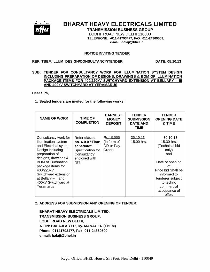


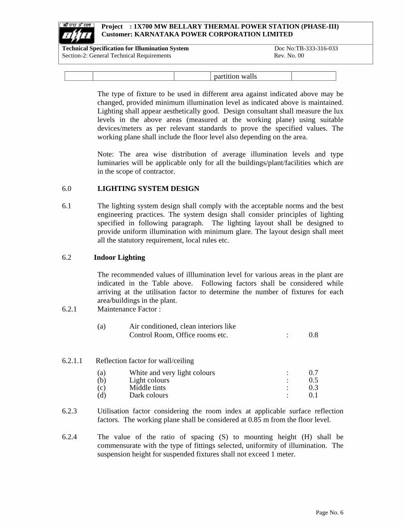

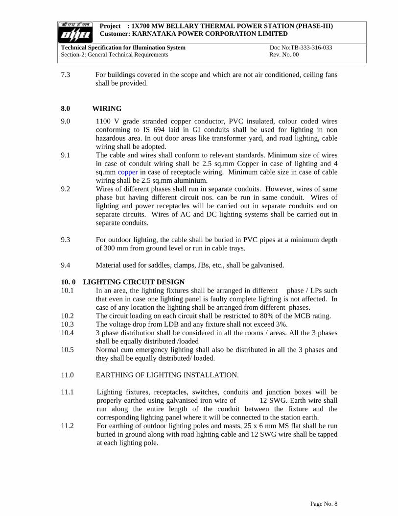


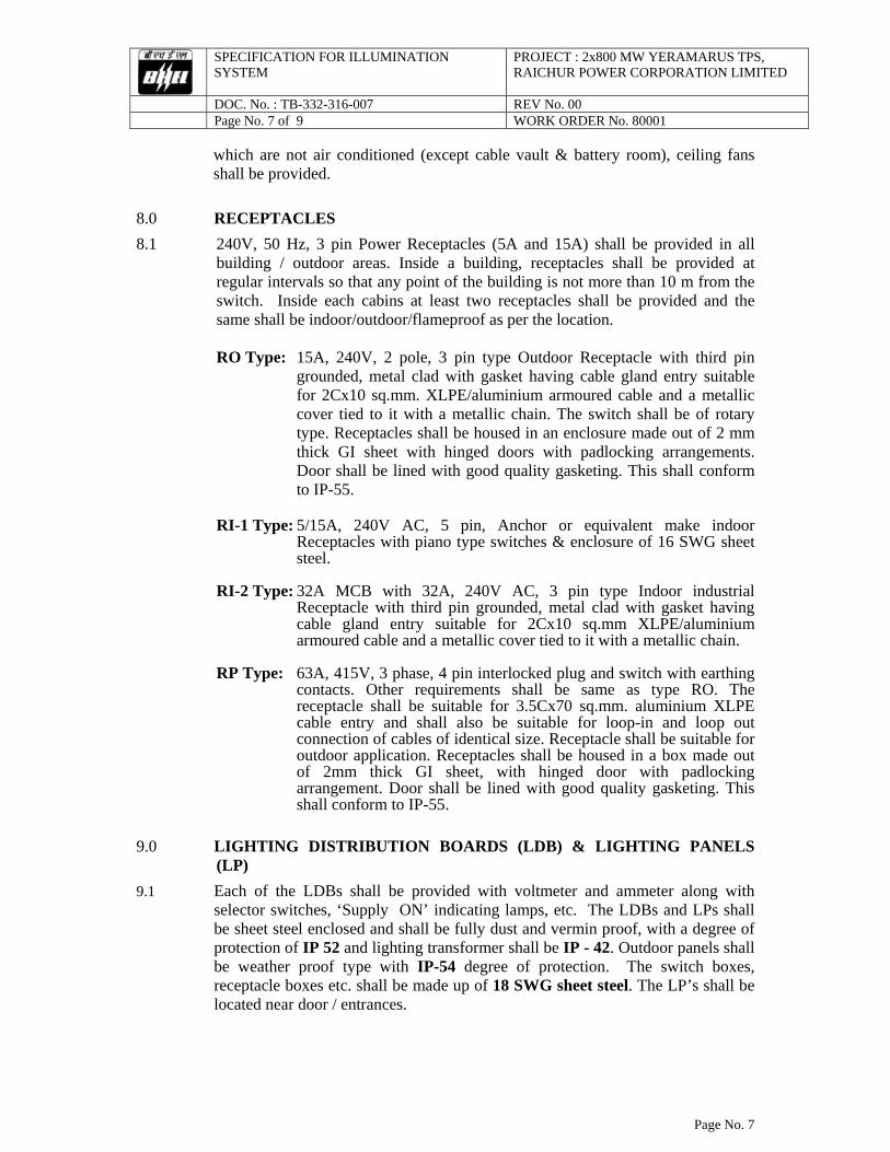


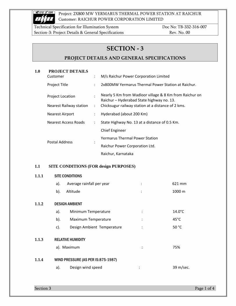

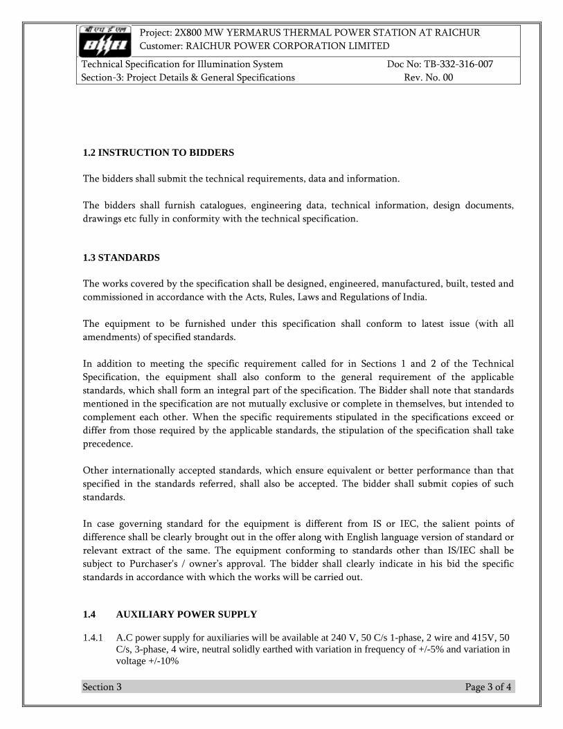


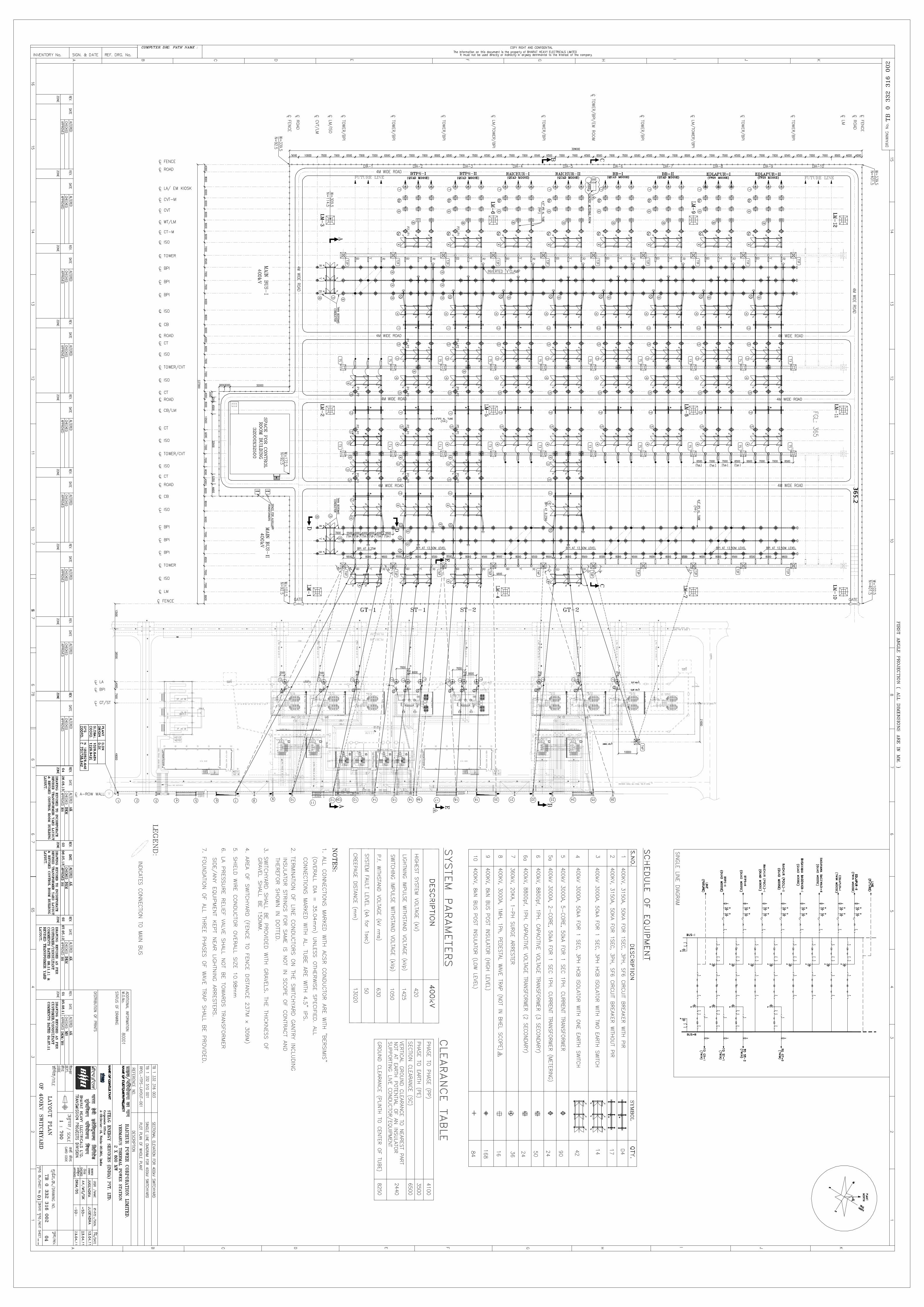


![Doc1[1] - Bharat Heavy Electricals Limited · page 1 of 4 bharat heavy electricals limited electroporcelains division, bangalore-12 tender for the supply of eot crane 2 ton general](https://static.documents.pub/doc/80x56/5f0362cb7e708231d408f4eb/doc11-bharat-heavy-electricals-page-1-of-4-bharat-heavy-electricals-limited.jpg)
