REPUBLIC OF KENYA MINISTRY OF HEALTH EAST AFRICA’S CENTERS OF EXCELLENCE FOR SKILLS AND TERTIARY EDUCATION IN BIOMEDICAL SCIENCES PROPOSED CONSTRUCTION OF EAST AFRICA’S KIDNEY INSTITUTE COMPLEX AT KENYATTA NATIONAL HOSPITAL (KNH) GROUNDS NAIROBI, KENYA Contract Identification No: MOH/EAKIP/ICB/004/2018-2019 ADB Loan Number: 2100150031997 PROJECT ID NO-P-Z1-IB0-023 ADB Loan Name: EAST AFRICA CENTERS OF EXCELLENCE; KENYA Works Programme No: D108 NB/NB/1801 JOB NO. 10398A _____________________________________________________________________________________ BIDDING DOCUMENT – VOL 2 BILLS OF QUANTITIES FOR BUILDERS WORKS (ALL RATES EXCLUSIVE OF TAXES) ______________________________________________________________________________ EMPLOYER PRINCIPAL SECRETARY MINISTRY OF HEALTH P.O BOX 30016-00100 NAIROBI, KENYA EMPLOYER’S REPRESENTATIVE WORKS SECRETARY STATE DEPARTMENT OF PUBLIC WORKS P.O BOX 30743-00100 NAIROBI, KENYA PROJECT MANAGER PROJECT MANAGER EAST AFRICA’S CENTRE OF EXCELLENCE PROJECT MINISTRY OF HEALTH P. O. BOX 30016 – 00100 NAIROBI, KENYA LEAD CONSULTANT M/S POLITECNICA INGEGNERIA ED ARCHITETTURA SOCIETA COOPERATIVA 220, VIA GALILEO GALILEI 41126 MODENA; ITALY OCTOBER, 2018
Transcript
REPUBLIC OF KENYA
MINISTRY OF HEALTH
EAST AFRICA’S CENTERS OF EXCELLENCE FOR SKILLS AND
TERTIARY EDUCATION IN BIOMEDICAL SCIENCES
PROPOSED CONSTRUCTION OF EAST AFRICA’S KIDNEY INSTITUTE
COMPLEX AT KENYATTA NATIONAL HOSPITAL (KNH) GROUNDS
1.8 Construction Stage ..................................................................................................... 6
Page 121 of 10
2-121
1.1 General Instructions
1. Maximum design foundation bearing pressure: 1000 kPa.
2. All levels on drawings refer to the top of concrete unless otherwise indicated.
3. Dimensions of beams are shown as Depth x Width.
4. All beams and structural slabs must be provided with an upward camber as shown
below unless indicated otherwise:
Cantilevers: Span divided by 200
All other spans: Span divided by 500
5. Joints, indicated in surface beds, slabs and beams, are also to be constructed in brick
walls, screeds and finishes.
6. The contractor must ensure that all embedded items for services have been provided for
and positioned, according to the latest drawings of all disciplines before casting concrete.
7. Provisions for props under slabs and beams: The contractor must ensure that beams and/or slabs have sufficient strength and/or are adequately propped to carry construction loads from above. Discuss with engineer. 8. Engineer to confirm excavation levels on site. Extra excavation down to acceptable
material shall be backfilled with mass concrete, unless otherwise specified.
9. Refer to architects drawings for concrete finishes, grooves, chamfers, etc. unless
otherwise shown all smooth surface concrete corners are to be provided with 20x20mm
chamfers.
10. Storage of cement: Cement shall not be stored for periods longer than 6 weeks, without the approval of
the engineer.
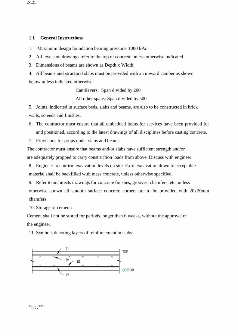
11. Symbols denoting layers of reinforcement in slabs:
Page 122 of 10
2-122
1.2 Setting out of works
1. The contractor shall request the principal agent for the information relating to the basic
reference pegs of the site with coordinates and benchmarks for the true and proper setting out
of the works to the contractor.
2. The contractor shall confirm in writing to the principal agent that all boundary pegs and
benchmarks have been identified, verified and found to be in position and delivery thereof is
accepted by the contractor. The contractor shall confirm this checking of the mentioned items
through a registered land surveyor. A land surveyor's certificate must be issued to the principal
agent.
3. The principal agent is responsible for the placing of the building(s) on the site. 4. The contractor is responsible for the true and proper setting out of the works and for the
correctness of the position, grid system, levels, dimensions and alignment of all parts of the
works. It is advisable that the contractor verifies this through a registered land Surveyor.
1.3 Concrete
1. Materials and mix proportions
1.1 The grades for concrete, unless otherwise indicated shall be as follows:
a) Columns Class 35 (35MPa) at 28 days
b) Bases Class 35 (35Mpa) at 28 days
c) Ground beams Class 30 (30Mpa) at 28 days
d) Retaining walls Class 30 (30MPa) at 28 days
e) Shafts and shear walls Class 30 (30MPa) at 28 days
f) Structural slabs Class 30 (30MPa) at 28 days
g) Mass concrete Class 15 (15MPa) at 28 days
h) Blinding layers Class 15 (15MPa) at 28 days
i) Stairs Class 30 (30MPa) at 28 days
1.2 When ready mixed concrete is used, test cubes are to be taken on site whilst casting.
1.3 Reinforcement for concrete shall comply with BS 4449
Mild steel yield stress = 250MPa
High tensile steel yield stress = 460MPa
Page 123 of 10
2-123
2. Concrete cover over reinforcement unless shown differently
a) Slabs and beams : 25mm.
b) Columns : 35mm cover to main reinforcement
c) Foundations : top 50mm;
: bottom and sides 50mm;
d) Walls : 30mm.
e) Ground beams : top and sides 35mm;
: bottom 35mm.
f) Retaining walls : 40mm.
3. Reinforcement shall be inspected by the engineer only after it has been completely
fixed in position, formwork is clean, spacers are placed in position, and the contractor has
inspected it himself.
4. Welding of reinforcement is not allowed unless it has been approved by the engineer in
writing.
5. 50mm blinding layer is to be provided under all bases unless indicated otherwise. 6. Construction joints:
a) No horizontal joints shall be allowed in bases, or other deep elements.
b) Construction joints are to be formed according to specification.
c) All pipes through joints, shall be provided with an expansion joint or flexible
coupling - this includes all cable sleeves, conduits and pipes.
d) No vertical construction joints shall be made in elements directly exposed to 7. Any additional construction joints required by the contractor must be clearly marked on a
drawing and submitted to the engineer for approval. These joints must be accepted in writing
by the engineer before any work commences.
1.4 Structural Steelwork
1. All hot rolled and cold formed steel shall have a guaranteed minimum yield stress of
350mpa and 200mpa respectively. The contractor shall provide test certificates to verify the
steel grade.
2. All relevant concrete and steel dimensions shall be checked on site before manufacture of
structural steel commences.
Page 124 of 10
2-124
3. All gusset plates shall be 8mm thick unless noted otherwise.
4. No field welds shall be permitted without the approval of the engineer.
5. All fillet welds shall be 6mm (min.) and shall be sealed and impervious unless noted
otherwise.
6. For full penetration field welds, backing plates shall be used. Tack weld backing plate to
appropriate member for shipment.
7. For full penetration shop welds, backing plates may be used or, back-up fillet welds may
be used at fabrication option, unless noted otherwise.
8. Omit paint within 50mm of field welded connections. 9. Shop splicing of members will not be permitted without prior written approval of the design
engineer. Approved splices shall have a capacity of 100% of the spliced member and
acceptance shall be subject to the results of non-destructive tests. Cost of splicing and
testing shall be borne by the fabricator.
10. All welding and surface preparation shall be discussed, inspected and approved by the
engineer in conjunction with approved inspection agency.
11. All bolted connections shall have a minimum of 2 bolts unless noted otherwise. 12. Slotted holes allowing 25mm total horizontal adjustment (12mm each side) shall be
provided when one or both ends of a steel member is fixed onto concrete or masonry.
13. Drilled holes for bolted connections shall be 2mm larger than the bolt diameter unless noted
otherwise.
14. Holes in structural base plates shall be 4mm larger than the anchor bolt diameter for M20
bolts and smaller, and 6mm larger for M24 bolts and larger.
15. Edge distance for connections shall be in accordance with BS 5950 unless noted otherwise. 16. Workshop detail drawings shall be checked by the engineer before manufacture of
structural steel commences.
17. Burrs and rough edges shall be ground prior to painting and welding of end plates, cleats,
and brackets.
18. Hold out-to-out dimensions exact for all continuous runs of beams to avoid an
accumulative error.
19. Paint specification: final paint colour to architect's schedules. 20. Grout:
a) Non-metallic, non-shrink grout, to be approved by engineer before use. Minimum
Page 125 of 10
2-125
compressive strength required at 28 days is 60 MPa. b) All grouting under mechanical equipment and structural steel plates by main
contractor.
c) Grouting under column base plates to be completed at least 7 days prior to erection of roof
and side cladding.
21. Galvanized structural steel to be hot dipped to 610g/m² according to BS EN ISO 14713. 22. The contractor shall be responsible for the stability of the structure until all elements have
been erected and fixed in position.
1.5 Stainless Steel Fabrication
1. Where welding is necessary, the appropriate "L" grade (low carbon content) shall be used.
2. Welding procedures shall be only those recommended by the stainless steel manufacturer.
Only suitably coded welders shall be employed (refer BS 4870 -1980 part 1 of ASME 1x
1983).
3. Fabrication of stainless steel components shall be carried out in clean workplaces where
there is no contamination by mild steel.
4. Grinding and polishing equipment shall be dedicated and shall not be contaminated with iron
or mild steel.
5. Stainless steel shall be suitably handled to avoid scratching the surface. 6. Pickling and passivation: cut edges, welds and heat treated surfaces shall be pickled and
passivated to remove all discolouration. Proprietary pickling and passivating pastes shall be
used in accordance with the manufacturer's recommendations. Care shall be taken not to exceed
the maximum contact time recommended.
After passivasion, surfaces shall be thoroughly washed with clean potable water to remove all
traces of acid. The surface shall be allowed to dry, then polished where
necessary, using polishing compounds recommended by the stainless steel manufacturer. 1.6 Excavation
1. Expansive soil, if any, in plinth and upto one meter beyond the outer face on all sides
shall be completely removed.
2. Before proceeding excavation in rock which requires use of pneumatic/Hydraulic
breakers reduced levels of the rock surface shall be recorded jointly with
consultant/owner’s representative at site.
Page 126 of 10
2-126
3. Wherever the termite mounds are observed within the vicinity of the building or in the
soil type exhibits the likely presence of termites it shall be immediately brought to the
notice of the consultant to enable him to take the necessary measures for the pre-
construction anti-termite treatment.
4. Land development activity, particularly earth filling activity for general site grading
shall be carried out prior to digging for foundation pits.
1.7 Filling
1. The material to be used for filling shall be soil, murrum, gravel or a mixture of these or
any other material as approved by the engineer. The material shall be free of organic
matter or any other deleterious material. Expansive clay like black cotton soil shall not
be used as a fill material.
2. Typical specifications of engineering backfill material shall be as follow:
a) Backfill shall be typically well graded silty sand.
b) Plasticity index and liquid limit shall be less than 6% and 20% respectively. Back
fill shall not be compacted with free water on the surface.
c) Prior to placement of backfill, approval of the material is required. 1.8 Construction Stage
1. Study carefully the GENERAL SPECIFICATIONS of material and trade mark
important points.
2. Read general notes and the technical information sheets.
3. Go through the abbreviations and symbols.
4. Also study the standard drawings carefully and note the peculiar details.
5. The contractor shall demand and take custody of the said drawings and documents
before commencement of work. In case of any doubts please ask us.
6. It is the responsibility of the contractor to ensure that all the work at site is being carried
out strictly in accordance with relevant drawings and specifications. No deviation will
be allowed without our prior written permission.
7. The contractor shall study the drawing release procedure; with every set of drawings a
fresh list of drawings will be issued. The list of drawings gives the exact status of
drawings including the number of copies issued, release status ( like for material
procurement, excavation, execution etc.) and revisions if any. The contractor shall
Page ii of 39
2-127
display the list of drawings on display board in the site office. Whenever a fresh list of
drawings is received ensure that the new list replaces the previous one on display board.
See for the revisions in drawings. Cancel the old drawings to avoid confusion.
8. Before commencement of any work the contractor shall ensure that the drawing he is
referring to bears an indication for execution and carries the latest revision number.
He shall check the revision number with the latest list of drawings.
9. The contractor shall study the execution drawings carefully well in advance of actual
execution. He shall mark the important details and notes. The consultant will not
be responsible in case the work is held up due to delay in answering last moment
queries.
10. Any discrepancy/omission shall be brought to the notice of the consultant prior to
execution.
Page ii of 39
2-128
STANDARD SPECIFICATIONS FOR
STRUCURAL CONCRETE
Page ii of 39
2-129
STRUCTURAL CONCRETE SPECIFICATIONS
Page cxxx of 39
2-130
Table of Contents
STRUCTURAL CONCRETE SPECIFICATIONS .................................................................. ii
1.9 Concrete Foundation Inspections ............................................................................... 2
1.10 Materials for Concrete ................................................................................................ 2
• General ................................................................................................................ 2
1.9 Concrete Foundation Inspections The Contractor is to report to the Engineer when the excavations are complete and ready for
inspection, prior to depositing concrete.
The Contractor is to excavate all load bearing bases to the founding strata, which is to be ap-
proved by the Engineer. All over-excavation is to be made up in mass concrete.
The Contractor is to allow safe access to enable the inspection to be carried out.
1.10 Materials for Concrete
1. General
This specification covers materials - including formwork - design, workmanship and testing
for mass and reinforced concrete.
2. Standards
All materials, workmanship and practices shall be in accordance with the current issue of the
listed Standards.
a) ACI 305 Recommended Practice for Hot Weather Concreting.
b) ASTM C 87 Effect of organic impurities in fine aggregate on strength of mortar.
c) ASTM C 142 Clay lumps and friable particles in aggregates.
d) ASTM C 227 Potential Alkali reactivity of cement - Aggregate combinations
(Mortar bar method).
e) ASTM C 289 Test for potential reactivity of aggregates (chemical method).
f) BS 12 Portland cement (ordinary and rapid hardening).
g) BS 812 Testing aggregates.
h) Part 1 Methods for determination of particle size and shape
i) Part 2 Methods for determination of physical properties
j) Part 3 Methods for determination of mechanical properties
k) Part 101 Guide to sampling and testing aggregates
l) Part 102 Methods for sampling
m) Part 103 Methods for determination of particle size distribution
n) Part 105 Particle shape: flakiness index
o) Part 106 Method for determination of shell content in coarse aggregate
p) Part 117 Method for determination of water - soluble chloride salts
q) Part 118 Method for determination of sulphate content
Page 135 of 39
2-135
r) Part 119 Method for determination of acid soluble material
s) in fine aggregate
t) BS 882 Aggregates from natural sources for concrete.
u) BS 1305 Batch type concrete mixers.
v) BS 1370 Specification for low heat Portland cement.
w) BS 1521 Waterproof building.
x) BS 1881 Testing concrete.
y) Part 1 Methods of sampling fresh concrete
z) Part 2 Methods of testing fresh concrete
aa) Part 3 Methods of making and curing test specimens
bb) Part 4 Methods of testing concrete for strength
cc) Part 5 Methods of testing hardened concrete for other than strength
dd) Part 6 Analysis of hardened concrete
ee) Part 101 Method of sampling fresh concrete on site
ff) Part 102 Method for determination of slump
gg) Part 106 Methods for determination of air content of fresh concrete
hh) Part 107 Method for determination of density of compacted fresh concrete
ii) Part 108 Method for making test cubes from fresh concrete
jj) Part 111 Method of normal curing of test specimens
kk) Part 112 Method of accelerated curing of test cubes
ll) Part 116 Method for determination of compressive strength of concrete cubes
mm) Part 122 Method for determination of water absorption
nn) Part 125 Method for mixing and sampling fresh concrete in the laboratory
oo) Part 201 Guide to the use of non - destructive methods of test for hardened con-
crete
pp) Part 202 Recommendations for surface hardness testing by rebound hammer
qq) Part 203 Recommendations for measurement of velocity of ultrasonic pulses in
concrete
rr) BS 2004 Foundations
ss) BS 2787 Glossary of terms for concrete and reinforced concrete.
tt) BS 3148 Tests for water for making concrete.
uu) BS 3681 Methods for sampling and testing of lightweight aggregates for con-
crete.
vv) BS 3797 Specification for lightweight aggregates for concrete
Page 136 of 39
2-136
ww) BS 4251 Truck type concrete mixers
xx) BS 4340 Glossary of formwork terms.
yy) BS 4408 Recommendation for non - destructive methods of tests for concrete.
zz) BS 4449 Hot rolled steel bars for the reinforcement of concrete.
aaa) BS 4461 Cold worked steel bars for the reinforcement of concrete.
bbb) BS 4466 Bending dimensions and scheduling of bars for the reinforcement of
concrete.
ccc) BS 4482 Hard-drawn mild steel bars for the reinforcement of concrete.
ddd) BS 4483 Steel fabric for the reinforcement concrete.
eee) BS 4550 Part 2 Methods of testing cement - chemical tests.
fff) BS 4627 Glossary of terms relating to type of cement, their properties and com-
ponents.
ggg) BS 5075 Part 1 Accelerating admixtures, retarding admixtures and water reduc-
ing admixtures. Metric Units.
hhh) BS 5328 Ready mixed concrete.
iii) BS 5337 The structural use of concrete for retaining aqueous liquids.
jjj) BS 5975 Falsework
kkk) BS 6089 Guide to assessment of concrete strength in existing structures.
lll) BS 6100 Glossary of building and civil engineering terms.
mmm) BS 8007 Code of practice for design of concrete structures for retaining aqueous
liquids.
nnn) BS 8110 The structural use of concrete.
ooo) CP 116 The structural use of precast concrete.
3. Independent Testing Laboratory
The Contractor shall obtain the Engineer’s approval of his proposed materials testing labora-
tory.
4. Test Certificates
Two copies of certificates verifying that the material used complies with these Specifications
shall be promptly submitted to the Engineer at the intervals specified below.
a) Aggregate - each 500 cubic metres or weekly for each aggregate
b) Cement - each consignment
c) Water - at commencement of work then monthly.
Page 137 of 39
2-137
5. Source of
Supply
At the start of the contract and at the Engineer’s request, the Contractor shall submit for ap-
proval the name of the source from which it proposes to obtain aggregates, together with evi-
dence showing that the material satisfies the requirement of the appropriate British Standard,
and additional information required by Clause 7 BS 882 and this Specification.
6. Cement
The cement to be used throughout the Works shall be Portland Cement - unless specified oth-
erwise and shall be as described under one of the following headings:
a) Ordinary Portland Cement (OPC) equivalent ASTM C 150 Type I
Cement complying with BS 12 but containing not less than 8% and not more than 13%
proportion by weight of tri-calcium aluminate.
b) Moderate Sulphate Resisting Portland Cement (MSRC)
Cement complying with BS 12 but containing not less than 4% and not more than 8%
proportion by weight tri-calcium aluminate, or cement complying with ASTM C150
Type II. In either case the cement shall not contain more than 2.7% proportion by
weight of Sulphur trioxide.
c) Sulphate Resisting Portland Cement (SRC)
Cement complying with either BS 4027 or ASTM C 150 Type V
d) Low Heat Portland Cements (LHC)
Low heat generating cements such as :- • Portland Blast furnace to BS.146:Part 2 ; • Low Heat Portland to BS.1370 ; or • Low Heat Portland Blast furnace to BS.4246:Part 2
may be used in the concrete mix when control of heat of hydration is called for.
7. Common Requirements
The temperature of the cement shall not exceed 75ºC at the time of incorporation into a concrete
mix.
Each consignment of cement shall be kept separate, identified with an appropriate certificate
detailing place of manufacture and results of specified test carried out on the original bulk
supply and used in order of delivery.
Page 138 of 39
2-138
In addition to tests carried out by the manufacturers, the Engineer shall from time to time re-
quire tests to be carried out in accordance with the British Standard and at the Contractor’s
expense.
Cement purchased in bulk shall be in purpose built containers that are maintained in good con-
dition to the approval of the Engineer. Bag cement shall be stored in a weather tight building,
which shall be damp proof and well ventilated. The cement shall be stored in such a manner as
to permit easy access for proper inspection and identification of each consignment.
Any consignment of cement not used within six months from the date of manufacture shall not
be used in the Works.
8. Aggregates
Aggregate shall comply with BS 882 and the following:
a) Coarse Aggregate
Aggregates that are deleteriously reactive with the alkalis in the cement in an amount
sufficient to cause excessive expansion of concrete shall not be used.
b) Fine Aggregate
Aggregates that are deleteriously reactive with the alkalis in the cement amount suffi-
cient to cause excessive expansion of concrete shall not be used.
Grading for the aggregates shall be within the limits specified.
c) Aggregate Shrinkage
Drying shrinkage of aggregate not to exceed 0.05%.
9. Storage Aggregates shall be stored on a hard, dust-free surface and shielded from dust and the sun.
Aggregates of each grade and type of material shall be kept separate until batched. Segregation
in each stockpile shall be prevented.
Stockpiles shall be protected against contamination from soil, vegetable matter or other dele-
terious material.
The floors of bins shall be 75mm thick mass concrete (or equal and approved) and shall be laid
to fall to the outer edge or provide a free draining apron.
Page 139 of 39
2-139
• Water Water shall be clean and free from salt and other impurities to the satisfaction or the Engineer.
It shall be tested in accordance with BS 3148.
Water used for mixing and curing of concrete shall have a PH value in the basic range of 7 to
9.
• Admixtures Unless specified in the drawings, the use of admixtures is not permitted without the prior ap-
proval of the Engineer. In any case, the suitability of the admixture shall be verified by trial
mixes.
Admixtures if approved, shall be used in strict accordance with the manufacturer’s instructions.
Neither Calcium Chloride nor any admixture containing it shall be used.
The following data pertaining to the proposed type of admixture shall be submitted to the En-
gineer for his information and consideration. These are:
• The chemical name(s) of the main active ingredient(s) in the admixture.
• Whether or not the admixture contains Chlorides
• The typical dosage and detrimental effects of under-dosage and over-dosage.
• Whether or not the admixture leads to the entrainment of air when used at the
manufacturer’s recommended dosage.
• Long term and short term effects of the admixture on concrete and the effect of
different types of cement and aggregate.
• Storage life and any special storage requirements.
• Safety precautions in handling.
• Availability of on-site technical service. • Admixtures shall comply with one of the following British Standards
BS 1014, BS 3587 or BS 5075 as appropriate. Air entrainment agents shall be such that the air content can be maintained within the limits
specified even if the mixing time is extended to 30 minutes.
If two or more admixtures are proposed to be used in any one mix, the manufacturers of each
shall be consulted and their advice passed to the Engineer.
Admixtures for improving the workability of the concrete or as a retarding agent shall only be
permitted when the type and dosage of the additive is clearly stated in the proposed design mix
Page 140 of 39
2-140
and supported with sufficient evidence, in the form of manufacturer’s certificates or proven
trial tests of the suitability of the materials of the additive and its effectiveness.
When proposing an admixture for the workability of the concrete, the Contractor must specify
range of slump to be expected.
Should more than three tests of a delivery fail to achieve the expected slump within the speci-
fied range, the concrete delivery stand condemned.
Also, should a failure in this fashion reoccur in twelve successive deliveries, the entire mix
design shall be deemed dissimilar to the approved design mix and its further usage in the project
will immediately cease.
In this event, no concreting from the supplier of the condemned concrete shall be permitted
and the Contractor must obtain fresh approval of the materials, design mix and its further usage
in the project will immediately cease.
When an admixture is specified as a retarding agent, the Contractor must specify the recom-
mended retarding period, i.e. the time period between dispatch from plant to pouring on site.
The concrete delivery is deemed condemned if the retarding period is exceeded.
However, its acceptability will only be at the Engineer’s discretion. The above rules apply when one additive is proposed and approved for the combined purpose
of workability and retardingness.
• Concrete Mix Design • General The grades of concrete are stated in the Specification and Drawings by reference to the 28-days
characteristic compressive strength in N/sq. mm without accelerated curing.
The proportions of the ingredients of the concrete including the water, shall be so chosen that
the concrete will be workable enough to be fully compacted and not be prone to segregation or
bleeding.
The mix shall be such that there will be no excess water on the top surface on completion of
compaction. It may be necessary to reduce the water content of batches at the top of deep lifts
to compensate for water gain from the lower levels, but this should be avoided by designing
the mix, checking with preliminary trials and accurately controlling the mix proportions
throughout the work.
Designed mixes shall comply with the requirements BS 8110. The Contractor’s mix proposals
for each mix require the Engineer’s approval. Existing data provided as evidence of satisfactory
Page 141 of 39
2-141
previous performance shall include the workability and water/cement ratio. During production
the Contractor shall inform the Engineer of all changes in sources of materials or cement con-
tent. The Engineer will require trial mixes to be made initially and before any substantial
change is made. No changes shall be made without the Engineer’s approval.
• Blinding Blinding concrete and mass concrete to over - excavation shall be Class 15. It shall provide a
dense layer/mass impervious to the fines of subsequent concrete placed thereon.
• Air Content The average allowable air content of the fresh concrete (other than those from air-entraining
agents) shall be 1%.
The percentage of air content determined from individual samples taken at the point of placing
the concrete and representative of any given batch of concrete shall be within +/- 1.5 of the
required value. The average percentage air content from any four consecutive determinations
from separate batches shall be within +/- 1.0.
• Workability The workability shall be measured by slump cone and shall not be less than 25mm and not
more than 75mm without the Engineer’s permission.
• Maximum Salt Content of Concrete The total content of soluble Chlorides (expressed as Cl) in concrete containing Ordinary Port-
land Cement shall not exceed 0.3% by weight of cement.
The total content of soluble Chlorides (expressed as Cl) in concrete containing Sulphate resist-
ing cement shall not exceed 0.15% weight of cement.
The total content of soluble Sulphates (expressed as SO3) shall not exceed 4% by mass of
cement in the mix.
The limits for salt contents aggregates specified in Section 3.0 may need to be reduced to com-
ply with the above.
• Alkali Aggregate Reactions It is the responsibility of the Contractor to demonstrate to the Engineer’s satisfaction that the
alkali resistivity of the complete concrete matrix will be stable and not liable in the future to
breakdown and loss of strength.
The Contractor shall submit to the Engineer test certificates for:
Page 142 of 39
2-142
• Petrographic tests of the sand and aggregates proposed for the concrete and mortar
mixes.
• Cement alkali content. Also required are test certificates from an independent testing laboratory for:
8. Quick Chemical Test to ASTM C 289
9. Mortar bar test to ASTM C 227.
The test will be repeated at interval to be agreed with the Engineer and the cost of all testing to
be allowed for by the Contractor in its Tender.
• Workmanship • Batching and Mixing
e) The quantity of cement, the quantity of fine aggregate and the quantity of the various sizes
of coarse aggregate shall be measured by weight.
f) A separate weighing device should be provided for weighing the cement. Alternatively, the
cement may be measured by using a whole number of bags in each batch.
g) The amount of water should be measured, by volume or weight. Any solid admixtures to
be added should be measured by weight but liquid or paste admixture may be measured by
volume or weight.
h) The batch weights of aggregate shall be adjusted to allow for a moisture content typical of
the aggregate being used.
i) The accuracy of the measuring equipment shall be within +3% of the quantity of cement,
water or total aggregate being measured and within +5% of the quantity of any admixture
being used. All measuring equipment shall be maintained in clean, serviceable condition.
j) The mixer should comply with the requirements of BS1305 or BS 4251 where applicable.
The mixing time should not be less than that used by the manufacturer in assessing the
mixer performance.
k) For mixes of low workability or high cement content the Engineer may direct that the mix-
ing time be determined by tests to ensure that maximum strength is achieved.
l) Plant used for making concrete shall be free from any concrete or mortar containing either
high alumina or super - sulphated cements.
Page 143 of 39
2-143
• Ready Mix Concrete
23. Ready mixed concrete shall comply with the requirements of this Specification and with
BS 5238, except for those Clauses, which are directly over-ridden by this Specification, and
the Supplier shall be made aware of the requirements of these documents.
24. Concrete shall only be mixed at a depot approved by the Engineer. Unless specially author-
ised by the Engineer, the concrete shall be mixed and the water added to mixer at the depot.
25. No additional water shall be added at any stage from batching to placing. When the Engi-
neer is asked to authorise dry batching, he will require to be satisfied that appropriate steps will
be taken to ensure the quality, consistency and strength of the concrete as placed and that the
water will be added to the dry ingredients under properly controlled conditions.
26. Truck mixers shall comply with BS 4251 and the mixing performance when tested in ac-
cordance with BS 3963 shall be within the limits of Table 5 of BS 1305.
27. The drum of the truck agitator or truck mixer shall be completely clean and empty before
it is filled with concrete. Trucks shall not be loaded in excess of the manufacturer’s rated
capacity, which shall be displayed on the vehicle in terms of the column of mixed concrete.
Trucks shall be discharged within thirty minutes after the introduction of the water to the
cement unless a longer time is authorised by the Engineer.
28. If a delay exceeding thirty minutes occurs during the concreting of a floor slab or beam,
concreting shall be completed against a newly placed stop end. If this joint is not in a sat-
isfactory position, the Engineer will require the concrete to be cut back to an acceptable
position. In any case unloading must be completed within one and half hour of batching.
• Compacting Concrete
d) Concrete should be thoroughly compacted by vibration during the operation and thoroughly
worked around the reinforcement and embedded fixtures and into corners of the formwork to
form a solid mass free from voids and which will have the required surface finish when the
formwork is removed. When vibrators are used to compact concrete, vibration should be
applied continuously during the placing of each batch of concrete until the expulsion of air has
practically ceased and in a manner, which does not promote segregation of the in- gredients.
The vibrators shall be applied systematically and at such intervals that the zones of influence
overlap. The vibrator shall be applied at any point only for such a period that the concrete is
properly compacted and not for such time that segregation occurs.
Page 144 of 39
2-144
e) Whenever vibration has to be applied externally the design of formwork and disposition of
vibrators should receive special consideration to ensure sufficient compaction and to avoid
surface blemishes.
f) When directed by the Engineer the Contractor shall demonstrate the efficiency of the pro-
posed method of construction on a trial section prior to the commencement of the perma- nent
works.
g) Sufficient standby equipment shall be retained on site during concreting operations to en-
sure that suitable equipment is always available in the event of breakdown.
• Curing Concrete Concrete shall be protected from adverse weather conditions after placing. It shall be cured to
ensure that it has satisfactory durability and strength, the minimum distortion, freedom from
excessive efflorescence and will not cause, by its shrinkage, undue cracking in the structure.
To achieve these objectives, it may be necessary to insulate the concrete so that it is maintained
at a suitable temperature, or so that the rate of evaporation of moisture from the surface is kept
to appropriate level, or both.
Concrete shall be cured for 7 days. Where structural members are of considerable depth or bulk or have a usually high proportion
of cement or the concrete incorporates admixtures or is subjected to special or accelerated cur-
ing methods, the method of curing requires the approval of the Engineer.
The Contractor shall submit for the Engineer’s approval, its proposed methods of curing for all
concrete members. The Engineer’s approval will be conditional until the proposed method
proves to be satisfactory on site. In the event that the cured concrete does not, in the Engineer’s
opinion, meet the requirements of the Specification, the Contractor shall submit proposals for
an alternative method of curing.
The following methods of curing may be adopted:
• Covering with an absorbent material; such as Hessian; to be kept damp during the cur-
ing period with clean water; or
• An impermeable sheet; such as polythene sheet; covering the area to prevent the evap-
oration while the surface is kept flooded with water.
• Resin based curing compound.
Page 145 of 39
2-145
Alternate wetting and drying is not permitted, especially in the form of cold water applied to
warm concrete surfaces. In order to avoid surface cracking, cold water shall not be applied to
members immediately after striking the formwork while the concrete is still warm.
• Protecting Concrete
7. Concrete shall be protected to prevent damage from weather, plant, overloading or any
other causes.
8. Concrete surfaces, which are to be exposed at the completion of the works, shall also be
protected to prevent discolouration or disfiguration from rush and damage by falling mate- rials
or by any other cause.
9. Before making good any damage, the Contractor shall obtain the Engineer’s approval of
the methods and materials proposed.
10. No concrete shall be broken down or demolished without the prior knowledge and approval
of the Engineer.
• Concreting in Hot Climates During hot weather concreting precautions shall be taken to ensure that the concrete will be
placed at the coolest temperature practicable. In no case shall the temperature of the concrete
on placing be more than 32oC.
Also, concrete shall not be mixed or placed when the shade air temperature is 40o C or
above or is expected to reach such a level during concreting and 3 hours after placing.
The following measures shall be taken by the Contractor as directed by the Engineer.
• The stores of cement and stockpiles of aggregate shall be kept shaded from the direct
rays of the sun.
• The water for concrete making is to be kept shaded from the sun and appropriate
measures taken to ensure that the water temperature is kept as low as possible. When flaked
or crushed ice is added to the water for concreting, it shall be completely melted prior to the
addition of water to the concrete mix. However, the temperature of the water used for curing
purpose shall not be much lower than the placed concrete temperature.
• Stockpiles shall be kept moist by water sprays. The Contractor shall control these with
great care to ensure a constant moisture content of the aggregate at all times and demon- strate
its ability to do so to the Engineer’s satisfaction.
• In a prevailing arid wind, temporary wind breaks shall be provided.
Page 146 of 39
2-146
• All surfaces on which concrete will be placed shall be moist but free of standing water
at the time of concreting by spraying the forms and reinforcement prior to placing con- crete.
• The concrete mixing plant, mixers, pipelines, pumps and chutes etc. shall be shaded
and / or painted white. The pump lines and other surfaces can be kept appreciably cooler by
covering them with damp hessian and kept damp by spraying with water.
• When daytime temperature and drying conditions may be critical, the concreting shall
be scheduled to begin in the later afternoon to prevent the occurrence of severe thermal effects.
1.5 Construction Joints
1.5.1 General Construction joints shall be deemed to include stop ends and crack inducing joints.
The number of construction joints shall be kept to the minimum necessary for the execution of
the work.
Prior to casting, the Contractor shall submit, for the Engineer’s approval, details and locations
of the proposed construction joints.
Construction joints shall be at right angles to the member. Formed joints shall have a key unless
shown otherwise on the Drawings. The reinforcement shall continue through the joints unless
directed otherwise. Joints shall be located to meet the requirements of the finish, e.g. granolithic
finish on floors.
1.5.2 Horizontal joints in columns and walls
Concealed joints in columns and walls shall generally be formed about 15mm above the soffits
of suspended floors, at floor levels, and at the tops of kickers, which shall not be less than
75mm high. Joints in other locations may be allowed at the discretion of the Engineer. Joints
in exposed concrete members will be located strictly in accordance with Engineer’s drawings.
When required by the Engineer, the Contractor shall submit AUTOCAD workshop drawings
showing his proposed locations of joints for the Engineer’s approval.
In certain circumstances the Engineer may limit the number of joints allowed in a vertical
member in accordance with the requirements of the design.
Contractor shall also arrange for a sample element with treated / finished joints for the Engi-
neer’s approval.
Page 147 of 39
2-147
1.5.3 Kickers Concrete in kickers shall be of the same mix as the main member. The concrete shall be vibrated
or rammed into place and prepared as for other joints.
1.5.4 Guidelines for the location of joints
The Contractor’s proposals for the location of construction joints shall be based on the follow-
ing guidelines:
a) The number of construction joints should be kept as few as possible, consistent with
reasonable precaution against the effects of shrinkage; their location shall take due ac- count of
shear and other stresses. Joint lines shall be arranged so that they can coincide with features of
the finished work.
b) Joints in slabs on ground shall coincide whenever practicable with the locations of joints
as shown on the drawings. Where additional joints are required, their location shall be to the
approval of the Engineer.
c) Joints in unreinforced slabs on ground (including slabs normally reinforced with not
more than 0.1% steel in either direction) shall be centres not greater than 5m.
d) Vertical joints in walls generally shall not be spaced at intervals greater than 6m. Where,
however, a wall changes direction by at least 600 C the overall spacing of the joints may be
increased to 10m subject to the length of pour in either leg of the wall being no more than 5m.
Where possible joints should be positioned at least 2m away from cor- ners.
e) Joints in a suspended floor system, if required, shall be 1/4 and 1/3 points of the span
unless otherwise directed by the Engineer. It is preferable that no joints are formed in the end
bays.
1.5.5 Movement Joints
Movement joints are those, which are designed to permit relative movement of adjacent parts
of a member or structure without impairing its structural integrity.
Movement joints shall be formed in the locations and to the details shown on the Drawings.
1.5.6 Materials
Materials forming the joint - if not specified by name - require the Engineer’s approval with
full technical details and a sample to be submitted. All materials to be installed strictly in ac-
cordance with the manufacturer’s recommendations.
Page 148 of 39
2-148
1.5.7 Joint filler material
As directed by the Engineer or as specified on the drawings joint fillers shall be semi-rigid non-
absorbent closed cell material, which has the following properties:
a) Resilient, low load transfer, compressible, high recovery after compression.
b) Non-tainting, non-extruding.
c) Bitumen free and Rot proof.
1.5.8 Slip membrane
Slip membrane shall be slip strip by serviced or approved equivalent
1.5.9 Damp proof membrane
DPM shall be bituminous material with PVC backing to Engineer’s approval.
1.5.10 Sealants
Joint sealant shall be a two-part polysulphide sealant to BS 4254, of a suitable colour to Engi-
neer’s approval.
1.5.11 Dowel bars
Dowel bars shall be straight, round steel bars, which comply with BS 4449 and have no defor-
mation.
Where shown on the drawings, dowel bars shall be debonded with an approved debonding
compounded or proprietary dowel bar sleeve. Dowel bars shall be rigidly supported so that they
are parallel and in the same place ensuring efficiency of the joint.
1.6 Concrete Finishes
1.6.1 Finishing formed surface Before commencing work the Contractor may be instructed to construct suitable, agreed, full-
scale samples with reinforcement to show each type of finished formed surfaces for approval.
These samples shall be typical of the structure being constructed and shall include junctions
between members and joints. The approval samples shall be retained as models and the finished
work shall not be inferior to the appropriate sample.
All forms shall be true to shape and free from defects likely to detract from the general appear-
ance of the finished concrete surface.
Concrete exposed by the removal of formwork shall be inspected by the Engineer, before any
remedial work or subsequent treatment of any kind.
The finish of formed surfaces shall be Type F1, F2, F3 or special as explained below.
Page 149 of 39
2-149
A. Type F1 Finish
This finish is obtained by the use of properly designed formwork or moulds of closely
joined sawn or wrought boards or other suitable material. The surfaces will be imprinted
with the grain of the boards and their joints. In addition, small blemishes caused by
entrapped air or water may be expected but the surface should be free from avoids,
honeycombing or other large blemishes. Fins and irregularities projecting more than
3mm shall be cleaned off.
B. Type F2 Finish
This finish is obtained by the use of properly designed forms of closely jointed wrought
boards, plastic, steel or other suitable material, provided that the surfaces shall be free
from the imprint of the forms. Small blemishes caused by entrapped air or water may
be expected, but the surface should be free from voids, honey-combing or other large
blemishes. The holes left by formwork bolts shall be filled. Fins and other projections
shall be removed and all blemishes repaired to the approval of the Engineer. Care
should be taken in the choice of any release agent used, to ensure that the finished con-
crete surface is not permanently stained or discoloured.
C. Type F3 Finish
This finish can only be achieved by the use of high quality concrete and by using
properly designed forms having a hard, smooth surface. The concrete surfaces should
be smooth with true, clean arises. Only very minor surfaces blemishes should occur and
there should be no staining or discolouration from the mould oil or curing agent.
The surface shall be free from the imprint of wood grain. Unfaced rough boarding or
standard panels shall not be used. The material for the form shall be provided in large
sheets and arrange in an approval uniform pattern.
Joints between sheets shall be arranged to coincide with architectural features, sills or
heads of windows or changes in direction of the surface; all joints between sheets shall
be accurately aligned in the plane of the sheets. Bold holes are not allowed.
D. Other Types of Finish (e.g. Fair Face)
These shall include any finish other than F1, F2, F3, which requires the use of special
forms or linings, the use of different concrete mix near the surface, grinding, bush ham-
mering, or any other treatment. If any of these special finishes is required it shall be
fully specified on the Drawings.
Page 150 of 39
2-150
When fair face finish is specified the Contractor shall submit the details of his formwork
type, assembly etc. for fairface concrete work for the engineer’s scrutiny and approval.
Once a provisional approval of the formwork is granted by the engineer the Contractor
shall prepare sample elements, e.g. walls, columns, slabs etc. as required for the Engi-
neer’s approval of the finished surface.
Remedial treatment to the finish of the concrete, additional to that specified above, re-
quires the approval of the Engineer.
1.6.2 Finishing Unformed Surfaces
The finish of unformed surfaces shall be tamped, floated, trawled or brushed as defined below
and shown on the Drawings.
The concrete finish surface shall not be wetted to assist the production of the surface finish.
Concrete surfaces to receive thin tile or sheet finishings shall be free from any defects, which
would adversely affect the appearance of the applied finish.
U1 (Tamped) - surface shall be formed by levelling and tamping the concrete to produced a
uniform plain or ridged surface, surplus concrete being struck off by a straight edge immedi-
ately after compaction. It is also the first stage of the following finishes.
U2 (Floated) - shall be a uniform surface, which has been worked, no more than if necessary
to remove screed marks by hand with a wood float or by power float of a type approved by the
Engineer. The surface shall not be floated until the concrete has hardened sufficiently.
U3 (Steel Trowelled) - shall be a hard, smooth finish free from trowel marks formed with a
steel trowel under firm pressure. Trowelling shall not commence until the moisture film has
disappeared and the concrete has hardened sufficiently to prevent excess laitance from being
worked to the surface. If laitance is brought to the surface it shall be removed.
U4 (Brushed) - shall be formed by first producing a U2 finish and then, before the concrete
has hardened by drawing a wire broom over the concrete surface at right angles to give an
average texture depth of 1 mm.
Power float finished surfaces where indicated on the drawings are to be free of marks and have
a uniform and “closed” texture and appearance.
Page 151 of 39
2-151
1.7 Compliance of Concrete with Specifications
1.7.1 General Requirements Provided that the specified materials have been used and the concrete has been properly made
and handled, concrete will be judged by the strength of the hardened concrete, in comparison
with the specified characteristic strength together with the cement content, in comparison with
the specified minimum cement content.
Sampling and testing of concrete shall comply with BS 1881, Parts 1 to 6 and be carried out in
the presence of the Engineer.
1.7.2 Sampling
Test samples obtained from a ready-mixed concrete production plant as part of its quality con-
trol system are for acceptable. Test samples shall be taken from ready mixed concrete on loca-
tion.
1.7.3 To Test for Workability
At least one sample shall be taken from each mix (OPC or SRC) of concrete each day and an
additional sample for each 5 cu.m. of structural concrete.
1.7.4 To Test for Strength
At least six cubes from each mix shall be made for each 30m3 of concrete, three shall be
tested at 7 days and three at 28 days age.
Additional samples will be required of all mixes until concrete production has been shown to
be at the Engineer’s satisfaction.
1.7.5 Testing workability
Each sample required shall be tested for workability.
For each mix of each grade the equivalent slump measured by the cone test shall be determined
by trial mixes. Control shall be maintained by measuring the slump at the point of placing.
1.7.6 Testing the strength
A standard 150mm cube shall be made from each sample taken and stored and tested at 28 days
in accordance with BS 1881.
Page 152 of 39
2-152
1.7.7 Report of the results of tests The reports of the tests for strength shall embody the information required by Clause 1.4 of BS
1881: Part 4, together with the information about the workability required by Clause 2.4, 3.4
of BS 1881: Part 2 and the information listed below:
a) Name of Contractor
b) Identification of mixer or ready mix supplier and depot
c) Grade of concrete
d) Type of concrete
e) Section of work represented by sample
f) Added water
g) Density of cube (kg/cu.m) Single copies of the completed report forms shall be given to the Engineer within 4 days of
each test.
A record of the statistical checks shall be prepared and supplied to the Engineer within 4 days
of preparation and 10 days of completion of a set of test results.
1.7.8 Compliance
Compliance with the characteristic strength shall be determined if:
a) The average strength of each group of 4 consecutive test cubes for each mix exceeds
the specified characteristic strength by not less than 7.5 N/sq. mm.
b) Each individual result exceeds 85% of the specified characteristic strength. Note the margin of 7.5 N/sq. mm may be adjusted by the Engineer at his discretion on the basis
of test results.
1.7.9 Action to be taken in the event of non-compliance
The action to be taken in the event of non-compliance shall be determined by the Engineer and
may range from qualified acceptance to rejection and removal of all or part of the concrete cast
between the previous set of 4 cubes and the next set of 4 cubes.
The Contractor shall provide at its own expense all records, samples including core samples,
tests and their results as may be required by the Engineer, whether the concrete is finally ac-
cepted or not.
1.8 Reinforcement
1.8.1 Materials Two copies of the certificates verifying that the reinforcement complies with this Specification
shall be given by the Contractor to the Engineer in accordance with Clause 15 of both BS
Page 153 of 39
2-153
4449:1997, and BS 4461:1978 for each consignment or reinforcement from each sources.
The Contractor shall submit two copies of the reinforcement manufacturer’s route test records
upon request by the Engineer.
Mild steel reinforcement shall be plain hot rolled bars complying with BS 4449. Unless otherwise directed, high yield reinforcement shall be either hot rolled deformed bars or
cold worked deformed bars complying with BS 4449 or BS 4461 respectively.
Fabric reinforcement shall be made from plain, indented or deformed wires, which shall be
welded, and it shall comply with BS 4483.
Tying wire shall be either 1.6m diameters galvanised steel wire or any other type, which has
the approval of the Engineer.
The type of spacer requires the approval of the Engineer. The materials and designs shall avoid
reinforcement corrosion and concrete spalling and be durable.
1.8.2 Schedules
The Contractor shall schedule the reinforcement in accordance with BS 8110 and the infor-
mation on the Drawings, this Specification and subsequent instructions.
The Contractor shall include for all necessary chairs and spacers, and its price and rates for
steel thus shown shall include for these. Approval by the Engineer of bending schedules and
reinforcement detail drawings shall not relieve the Contractor of its responsibility for their ac-
curacy.
1.8.3 Workmanship
1. Reinforcement shall be cut and bent in accordance with BS 4466. Cutting or bending by
the application of heat is not permitted. Welding of reinforcement shall only be permitted
unless approved in writing by the Engineer. The Contractor shall submit full technical de- tails
of its proposed procedures for such approval.
2. Reinforcement shall be secured against displacement outside the specified limits. Unless
specified otherwise:
a) The actual concrete cover as specified on the drawings shall not be less than the required
nominal cover minus 5mm.
b) Where reinforcement is located in relation to only one face of a member (e.g. a straight
bar in a slab) the actual concrete cover shall be not more than the required nominal cover
plus:
5 mm on bars up to and including 12 mm size
10 mm on bars over 12 mm up to and including 25 mm size
Page 154 of 39
2-154
15 mm on bars over 25 mm size
3. Cover shall be maintained to all embedded fixings, conduits and all chases and pockets.
Spacers, chairs together with such other supports as may be necessary, shall be used to
maintain the reinforcement in its correct position. In a member where the nominal cover is
dimensioned to the links, spacers between the links and formwork should be of the same
dimensions as the nominal cover.
4. Spacers shall be of such materials and designs as will be durable and not lead to corrosion
of the reinforcement and not cause spalling of the concrete cover. Spacers blocks made
from cement, sand and small aggregate shall match the mix proportions of the surrounding
concrete so far as is practicable with a view to being comparable in strength, durability and
appearance. Approved plastic spacers to be used where fair- face concrete is specified.
5. Non-structural connections for the positioning of reinforcement shall be made with steel
wire or tying devices. Care shall be taken to ensure that projecting ends of ties or clips do not
encroach into the concrete cover.
6. Reinforcement shall not be surrounded by concrete unless it is free of mud, oil, rust, grease
or any other substance, which may affect the steel or concrete structurally, chemically or
reduce bond.
7. The Contractor shall take whatever means necessary such as grit blasting, degreasing to
clean the reinforcement and protected by covering, painting until surrounded by concrete to
the approval of the Engineer.
1.8.4 Cutting and bending of reinforcement
All reinforcement shall be bent cold unless otherwise specially permitted by the Engineer.
Wooden mandrels or steel mandrels with nylon collars shall be used and the minimum internal
radius of bending shall be 4 bar diameters for both high yield and mild steel reinforcement. No
plain unribbed reinforcement shall be used unless specifically permitted by the Engineer.
1.8.5 Site installation and handing
Reinforcement of all types shall be stored on site in protected racks above ground in an ap-
proved manner so as to avoid damage to the coating. Direct metal coating contact should be
avoided wherever possible.
The reinforcement shall be lifted with nylon slings in accordance with Clause 10.1 of ASTM
A775.
The Engineer is to be notified of all errors and omissions prior to the cutting, bending and
fixing of the reinforcement.
Page 155 of 39
2-155
The Contractor shall provide adequate scaffold boards or similar to ensure that the reinforce-
ment is not displaced by being walked upon during the placing of the concrete or other opera-
tions. Prior to concreting, the Contractor shall ensure that the reinforcement is cleaned of all
concrete from previous pours and any damage to the coating is repaired.
1.9 Formwork
The design and use of formwork shall be in accordance with BS 5975:1982 Falsework.
1.9.1 Materials Temporary formwork shall be constructed of materials approved by the Engineer.
Permanent formwork shall be constructed of materials approved by the Engineer. Slabs or
blocks shall have an exposed surface of the specified quality; they shall
be positively anchored to the structure and the joints between them shall prevent bleeding of
cement paste from the concrete.
Representative samples of the material proposed for temporary and permanent formwork shall
be supplied by the contractor for the engineer’s approval.
The material for ties passing through the concrete requires the approval of the Engineer.
1.9.2 Design The design and construction of formwork shall be carried out by competent persons taking due
account of the surface finish required. The formwork shall be sufficiently rigid and tight to
prevent loss of grout or mortar from the concrete at all stages and for the appropriate method
of placing and compaction.
Formwork (including supports) shall be sufficiently rigid to maintain the forms in their correct
position and to correct shape and profile so that the final concrete structure is within the limits
of the dimensional tolerances specified. The supports should be designed to withstand the worst
• Quality system ................................................................................................... 28
• Additional inspections and tests ........................................................................ 29
• Records .............................................................................................................. 29
170
2-170
Structural Steel Specifications A
171
2-171
Structural Steel Specifications A
• Equivalency of standards Wherever reference is made in the Contract to British Standards and/or code requirements to
be met by the goods and materials to be furnished, work performed or tested, the provisions of
the latest edition or revision of the relevant British Standards and codes in effect shall apply,
unless otherwise stated in the Contract. Whenever reference is made to British Standards and
codes, other authoritative standards and codes that ensure an equal or higher quality than the
relevant British Standards and codes, will be accepted subject to the Project Engineer’s prior
review and written consent. Differences between the standards specified and the proposed al-
ternative standards shall be fully described in writing by the Tenderer/Contractor and submitted
to the Project Engineer at least twenty eight days prior to the date when the Contractor/Tenderer
desires the Project Engineer’s consent. In the event that the Project Engineer determines that
such deviations are not of a high enough or better standard, the Tenderer/Contractor shall com-
ply with the specified document.
A copy of the said specifications shall be furnished by the Contractor and shall be kept on the
site.
• Project specification
Should a requirement of the said standardized specification be inconsistent with a requirement of
the project specification, the latter shall take precedence.
• Applicable specifications
Structural steel specification part b: general specification • General specification
• Steel Product
The steel shall be Grade S355JR for hot rolled steel sections (I, H, C, L) and plates and Grade S275JR W for cold formed elements. All members shall carry the relevant steel symbol to iden-
tify steel grade prior to manufacturing.
The thickness specified of a checker (“vastrap”) floor plate, is the under-pattern thickness. • Drawing or Information
Review
The contractor shall furnish the engineer with shop-detail drawings within two weeks of having received the design drawings. Workshop drawings shall be drawn in AutoCAD. The engineer
will check the drawings for conformity with design requirements and will return the drawings
172
2-172
with additions and corrections, if any, within one week of having received them. Detailed
checking of shop details for dimensional accuracy and installation fit, will not be done by the
engineer.
• Welding Procedures
The applicable welding code for fabrication and erection is AWS D1.1.
• No staggered or intermittent welding is permitted.
• No welding on site is permitted unless approved by the engineer. Any site welder
and site welding procedure will have to be re-qualified for site welding.
• Weld testing
• General
• Personnel performing non-destructive testing other than visual shall be qualified in ac-
cordance with the stipulations of the code.
• Full penetration butt welds are to be radio graphically tested in accordance with the
clause below. A minimum of 50% of full penetration welds shall be tested. If more than
5% of the examined welds show unsatisfactory results, then additional examinations
covering all welds shall be performed.
• Non-destructive examination
• Non-destructive procedures, techniques and acceptance criteria shall be as required and
specified by the engineer.
• All non-destructive examination shall be in accordance with written procedures. The
Engineer shall have the right to examine and approve the written procedures.
• Full penetration butt welds shall be radio graphically tested or ultrasonically tested to
the specified requirements.
• Ultrasonic and radiographic examinations shall not be made within the period of 24
hours after completion of welding.
• Cost of examination listed under to be borne by the Contractor.
• All costs (time, travelling, tests) incurred by non-destructive examinations due to non-
conformance of specifications and due to any latent defects in material and welding
shall be borne by the Contractor.
• Fillet welds will be inspected and tested at the discretion of the Engineer. For costing
purposes allowance must be made for ultrasonic testing of at least 5 % of all fillet welds.
173
2-173
• Certificates of non-destructive testing shall be submitted to the Engineer. 1.3.2 Testing
Test certificates pertaining to the steel to be used shall be submitted to the engineer by the
contractor before fabrication commences.
The engineer reserves the right to inspect all structural steel in the workshop before it is deliv-
ered to the site.
• Additional clauses
• Protective treatment and painting
1.4.1.1 General h) All paint shall be delivered at the workshop as well as on the site in the original
containers that display the manufacturer’s name and trademark as well as the iden-
tification mark of the relevant Standards Authority. The engineer may, at his discre-
tion, prescribe the manufacturer and the type of paint. The coating system shall be
from one manufacturer only. The paint manufacturer’s instructions shall be strictly
adhered to.
i) Surfaces in contact with each other after assembly or erection shall receive the pri- mer beforehand, except for faying surfaces for friction-grip fasteners. j) The application of the final coats of paint before erection will be permitted by the
engineer only in special circumstances or where specified elsewhere.
k) After erection of the steelwork, the specified paint system shall be reinstated in all
areas where it has been damaged. All fasteners shall also be treated in accordance
with the specified paint system.
l) No painting on the site shall be done in inclement weather or when humidity or frost is liable to cause wet or damp conditions on the surface to be painted.
m) No painting shall be done if the temperature falls below 7oC. n) Welded seams shall be thoroughly steel-brushed before painting. Permission shall
be obtained from the engineer before slag residue may be neutralized with acids or
alkalis.
• Surface preparation in the workshop
ISO 8501 shall apply and shall be referred to in respect of this clause.
174
2-174
• Manual scraping and wire brushing. This treatment shall normally be applied in all circumstances except if and where blast cleaning
is specified.
• Prior to treatment, the steel surface shall be cleaned of dirt and grease
• Heavier layers of rust shall be removed by chipping
• All loose mill scale, rust and foreign matter shall be removed by very
• Finally the surface shall be cleaned by vacuum cleaner, with clean dry
compressed air, or with a clean brush
• The surface shall have a pronounced metallic sheen with an appearance
equal to or better than that shown on the prints in ISO 8501.
• Blast-cleaning This treatment may be used but is not obligatory unless so specified hereinafter. If blast cleaning
is preferred to normal scraping and wire brushing, the final sur- face shall be equal to or better
than that specified above.
• Paint system
The application may be by brush, roller or sprayed. Red lead may not be used. All structural steel which is not visible, e.g. purlins, rafters and trusses, shall receive only the
primer coat. All visible steel shall receive the full appropriate paint system treatment.
In all cases the manufacturer’s specification for any paint product must be followed. • Paint system for newly galvanized surfaces
• Recommended surface preparation:
• Degrease with Plascon Aquasole Degreaser GR 1 or similar approved. Any ce-
ment or foreign material must also be removed from the metal surface.
• Rinse with clean running water while protecting the floors and walls.
• Wash with Galvanised Iron Cleaner GIC 1 by Plascon, or similar ap-
proved.
• Rinse with clean running water and allow to dry. Protect the floors and
walls.
• Apply one coat of Plascon Aquafast Etch Primer no EMS 18 or similar approved
to a total dry thickness of 35 micron. Must be overcoated within 72 hours to
avoid excessive hardening.
175
2-175
• Apply the final coat as specified. 1.5.12 Hot dipped galvanizing
Steelwork described as "galvanised" shall be galvanised after manufacturing and before deliv-
ering to site by means of the hot dipped process complying with the minimum requirements of
BS EN ISO 1461), 1999 latest amendment. Structural steel members shall be given an 85 mi-
cron thick galvanised coating or such other thickness as may be specified in accordance with
BS EN ISO 1461.
Damaged surfaces must be thoroughly cleaned and if welding has been carried out all slag must
be removed preferably by the use of a chisel hammer.
Before galvanising all surfaces of the metalwork shall be thoroughly cleaned of all scale and
rust by shot-blasting in accordance with BS EN ISO 8501-1 or by pickling and then fluxed
ready for galvanising.
The zinc coating shall be even and continuous over all surfaces, free of bare spots, dull or rough
patches, blisters or other imperfections. The zinc coating shall show no signs of peeling and
shall be uniform in thickness.
All M8 and greater bolts, nuts, screws and other threaded components, shall be hot-dip galva-
nised to BS EN ISO 1461.
1.5.13 Repairing of damaged coatings
a) Plant repairs
Should any black spots or uncoated areas greater than 5 mm2 (individual) or 25 mm2 (collective)
per m2 or per m run be present after galvanizing, the coating shall be repaired. This is to be
carried out using abrasive blasting followed by zinc metal spray. The zinc metal spray shall be
applied at least 25 % thicker than that specified and shall overlap the damaged area by 20-25
mm. The finished coating shall be wire brushed to remove any excess metal spray.
Hot patch soldering is an alternative at the plant but is seldomly used, as the method needs to
be conducted while the product is still hot before quenching.
b) Site Repairs
This shall involve using a zinc rich paint provided it has at least 90 % zinc in the dry film, by
mass. The paint should be a zinc rich epoxy in conformance with BS EN ISO 14713. A single
pack zinc rich paint such as Plascon’s “Plascozinc Polygalv Primer” or equal can be applied.
176
2-176
Structural Steel Specifications B
177
2-177
Structural Steel Specifications B 1.5 Structural Steel Specifications B A. General
The structural steel framework is designed in accordance with the requirements of the latest
British Standard BS 5950 and all materials and workmanship shall be in accordance with that
standard unless specified otherwise.
All the technical notes given in the steelworks drawings are deemed to be part of the Specifi-
cation for the Works.
B. Equivalency of standards
Wherever reference is made in the Contract to British Standards and/or code requirements to
be met by the goods and materials to be furnished, work performed or tested, the provisions of
the latest edition or revision of the relevant British Standards and codes in effect shall apply,
unless otherwise stated in the Contract. Whenever reference is made to British Standards and
codes, other authoritative standards and codes that ensure an equal or higher quality than the
relevant British Standards and codes, will be accepted subject to the Project Engineer’s prior
review and written consent. Differences between the standards specified and the proposed al-
ternative standards shall be fully described in writing by the Tenderer/Contractor and submitted
to the Project Engineer at least twenty eight days prior to the date when the Contractor/Tenderer
desires the Project Engineer’s consent. In the event that the Project Engineer determines that
such deviations are not of a high enough or better standard, the Tenderer/Contractor shall com-
ply with the specified document.
A copy of the said specifications shall be furnished by the Contractor and shall be kept on the
site.
1.8 Materials 1.8.1 Steel products
a) Qualities
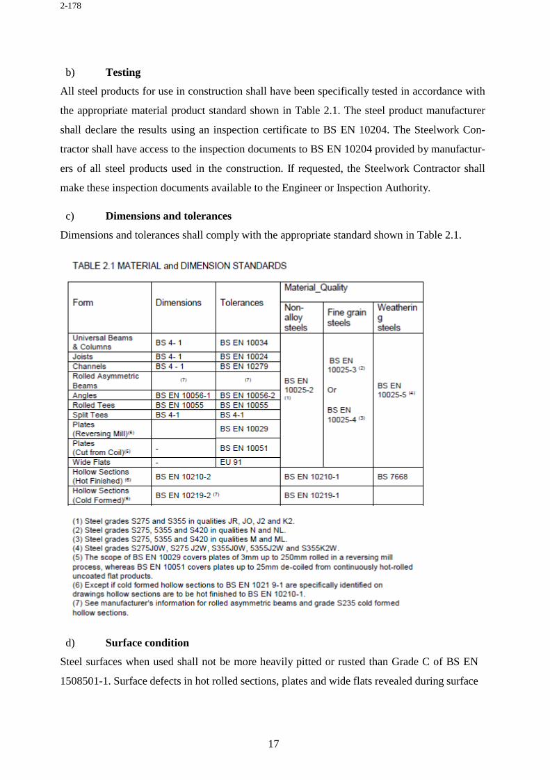
Material shall be steel in rolled sections, structural hollow sections, plates or bars and shall comply with the appropriate standard shown in Table 2.1. Note: When specifying and ordering,
full steel designation should be given including the standard number, strength grade and impact
quality (e.g. BS EN 10025-2 3275J0) so that the correct properties for fracture toughness and
weldability are ensured.
178
2-178
b) Testing All steel products for use in construction shall have been specifically tested in accordance with
the appropriate material product standard shown in Table 2.1. The steel product manufacturer
shall declare the results using an inspection certificate to BS EN 10204. The Steelwork Con-
tractor shall have access to the inspection documents to BS EN 10204 provided by manufactur-
ers of all steel products used in the construction. If requested, the Steelwork Contractor shall
make these inspection documents available to the Engineer or Inspection Authority.
c) Dimensions and tolerances
Dimensions and tolerances shall comply with the appropriate standard shown in Table 2.1.
d) Surface condition
Steel surfaces when used shall not be more heavily pitted or rusted than Grade C of BS EN
1508501-1. Surface defects in hot rolled sections, plates and wide flats revealed during surface
179
2-179
preparation which are not in accordance with the requirements of BS EN 10163 shall be recti-
fied accordingly. Surface defects in hot finished hollow sections revealed during surface prep-
aration which are not in accordance with the requirements of BS EN 10210-1 shall be rectified
accordingly. Surface defects in cold formed hollow sections revealed during surface preparation
which are not in accordance with the requirements of BS EN 10219-1 shall be rectified accord-
ingly.
1.8.6 Welding consumables
• Standards
Consumables for use in metal arc welding shall comply with BS EN ISO 2560, BS EN 440, BS
EN 756 or BS EN 758 as appropriate.
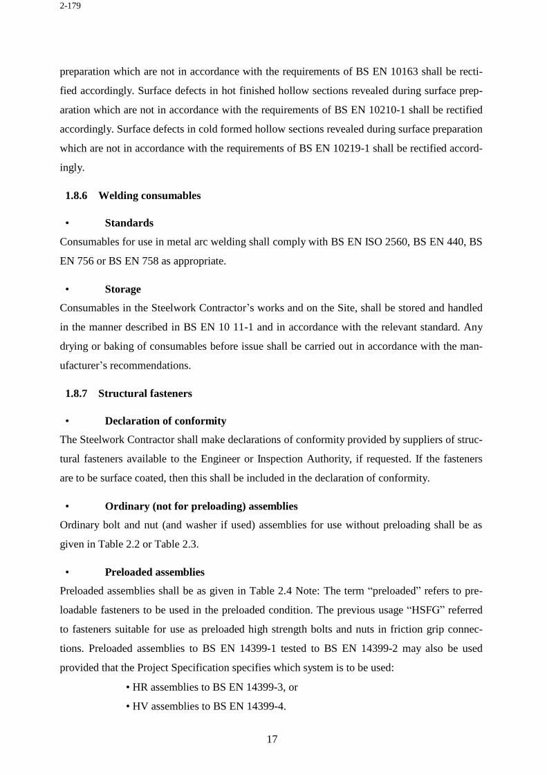
• Storage
Consumables in the Steelwork Contractor’s works and on the Site, shall be stored and handled
in the manner described in BS EN 10 11-1 and in accordance with the relevant standard. Any
drying or baking of consumables before issue shall be carried out in accordance with the man-
ufacturer’s recommendations.
1.8.7 Structural fasteners
• Declaration of conformity
The Steelwork Contractor shall make declarations of conformity provided by suppliers of struc-
tural fasteners available to the Engineer or Inspection Authority, if requested. If the fasteners
are to be surface coated, then this shall be included in the declaration of conformity.
• Ordinary (not for preloading) assemblies
Ordinary bolt and nut (and washer if used) assemblies for use without preloading shall be as
given in Table 2.2 or Table 2.3.
• Preloaded assemblies
Preloaded assemblies shall be as given in Table 2.4 Note: The term “preloaded” refers to pre-
loadable fasteners to be used in the preloaded condition. The previous usage “HSFG” referred
to fasteners suitable for use as preloaded high strength bolts and nuts in friction grip connec-
tions. Preloaded assemblies to BS EN 14399-1 tested to BS EN 14399-2 may also be used
provided that the Project Specification specifies which system is to be used:
• HR assemblies to BS EN 14399-3, or
• HV assemblies to BS EN 14399-4.
180
2-180
Components from the two different systems shall not be mixed. Plain washers to BS EN 14399-
5 and/or plain chamfered washers to BS EN 14399-6 may also be used with either of these
assemblies.
• Foundation bolt assemblies
Holding down bolt assemblies shall be as given in Table 2.5. • Cup and countersunk bolts
Cup and countersunk bolts shall be as given in Table 2.6.
181
2-181
• Lock nuts for bolt assemblies Lock nuts shall be in accordance with BS 4190. • Coatings for bolt assemblies
If specific coatings are required, they shall be provided by the fastener manufacturer and shall
182
2-182
comply with the appropriate part of BS 7371. Shear studs
Shear studs shall be in accordance with BS EN ISO 13918. Protective treatment materials
• Metallic blast cleaning abrasives
Chilled iron grit shall be in accordance with BS EN ISO 11124-2, and cast steel grit shall be in
accordance with BS EN ISO 11124-3.
• Surface coatings
Paint materials and other coatings supplied shall be in accordance with the appropriate British
Standard for the materials specified in the Project Specification
• Sherardized coatings
Sherardized coatings shall be in accordance with BS 7371-8. The thickness of the coating needs to
be specified.
• Galvanizing Materials
The composition of zinc in galvanizing baths shall be in accordance with BS 7371-6. • Electrodeposited coatings
Electrodeposited coatings shall be in accordance with BS EN ISO 4042. The thickness of the
coating needs to be specified.
Proprietary items
All proprietary items shall be used in accordance with the manufacturer’s recommendations
and instructions.
Substitution of material or form
Material quality or form of components may, with the agreement of the Engineer, be substituted
if it can be demonstrated that the structural properties are not less suitable than the designed
component and that compatibility with the intention of the design is maintained.
183
2-183
1.10 Information provided by the steelwork contractor 1.10.1 Fabrication information for components
Fabrication drawings and fabrication data
Fabrication Drawings or Fabrication Data used in the manufacturing system need only provide
details and dimensions necessary for the manufacture of components. Such details shall be
available to the Employer if so specified in the Project Specification. The system shall include
full details of the date when component information in the form of Fabrication Drawings and
Data is released for manufacture.
Attachments to facilitate erection
Details of holes and fittings in components necessary for safety or to provide lifting and erection
aids shall be included. Unless specified otherwise by the Project Specification, such holes and
fittings may remain on the permanent structure.
Welding
Any requirements for edge preparations for welds shall be indicated. Welding inspection re-
quirements which differ from the specified shall be clearly indicated.
Packs, clearances and camber
The Steelwork Contractor shall make provision for:
• Packs which may be necessary to ensure proper fit-up of joints,
• The need for clearances between the fabricated components so that the permitted
deviations in fabrication and erection are not exceeded,
• The Engineer’s requirements for pre-set or cambers. Hole sizes
Holes in components shall be shown to the following nominal sizes:
• For ordinary bolts and preloaded bolts:
not exceeding 24mm diameter - 2mm greater than the bolt diameter; greater than 24mm
diameter - 3mm greater than the bolt diameter.
(ii) For holding down bolts:
6mm greater than the bolt diameter, or with sufficient clearance to ensure that a bolt, whose
adjustment may cause it to be out of perpendicular, can be accommodated through the base
plate.
184
2-184
Holding down bolt cover plates Holding down bolt details shall include provision of loose cover plates or washers with hole
diameter 3mm greater than the holding down bolts.
Connections to allow movement
If the connection is designed to allow movement, the assembly used shall remain secure without
impeding the movement.
Machining note
Any machining requirements shall be clearly indicated. Drilling note
The component information shall indicate those locations where holes are to be drilled but not
punched or formed in another way.
Faying surfaces for friction grip connections
Faying surfaces which are to receive special treatment shall be identified.
1.11 Erection information 1.11.1 Erection drawings
If necessary to amplify the information given in the erection method statement Steelwork Con-
tractor shall prepare Erection Drawings.
1.11.2 Temporary steelwork drawings
Details and arrangements of temporary steelwork necessary for erection purposes shall be
shown with the erection information.
• Drawing or information review
• Submission to the Engineer
Drawings or Electronic Data shall be submitted for review by the Engineer in accordance with
the construction programme.
• Extent of submissions
Unless stated otherwise in the Project Specification the following drawings, and connection
calculations shall be submitted:
185
2-185
• General Arrangement Drawings. The Steelwork Contractor shall mark references on the
General Arrangement Drawings or provide another suitable system such that a connec-
tion calculation or standard simple connection can be identified to a specific location on
the structure.
• Connection Design calculations except for those where industry standard simple con-
nections are used. Calculations shall include sketches or drawings showing the arrange-
ment of the connection and shall be referenced to a location on the structure. If neces-
sary, drawings showing complex geometry shall also be submitted.
1.10 Workmanship 1.10.1.1 General • Identification
• Traceability of steel products
All steel products to be used in The Works shall have a reference to a suitable declaration of conformity so that the properties are known and can be verified. Unless required by the Project
Specification individual pieces do not need to be traceable to a particular inspection document.
• Material identification
The material grade, quality and other relevant properties shall be identifiable within the manu- facturing system. • Marking steelwork
Individual pieces shall be capable of positive identification at all stages of fabrication. Com- pleted components shall be marked with a durable and distinguishing erection mark in such a
way as not to damage the material. Hard stamping may be used for steel grades up to and in-
cluding S355, except where otherwise specified in the Project Specification. Where areas of
steelwork are indicated on the drawings, or fabrication information, as being unmarked, they
shall be left free of all markings and hard stamping.
1.11.6 Handling
Steelwork shall be bundled, packed, handled and transported (as appropriate) in a safe manner
so that permanent distortion does not occur and surface damage is minimized. Particular care
shall be taken to stiffen free ends and adequately protect any machined surfaces.
186
2-186
1.11.7 Cutting and shaping • Cutting operations
Cutting and shaping of steel may be carried out by sawing, shearing, cropping, thermal cutting, nibbling, planing or machining. Hand-held cutting shall only be used if it is impractical to use
machine thermal cutting. Any areas where thermal cuffing is not permitted shall be so indicated
by the engineer.
• Thermally-cut edges
Thermally-cut edges which are free from significant irregularities shall be accepted without further treatment except for the removal of dross. Otherwise cut edges shall be dressed to re-
move irregularities.
• Columns and compression members
Columns and compression members with ends not in direct bearing or intended to be erected on packs shall be fabricated to the accuracy. Columns and compression members intended to
be in direct bearing shall be fabricated to the accuracy as specified. The butting surfaces of
column sections which are one meter and over in width or depth and are to be in direct bearing,
shall be specially prepared so that after erection both the deviation in plumb and the permitted
gap are not exceeded.
1.10.5 Machining
The thickness of machined parts shown on the drawings as requiring machining shall mean the
minimum thickness after the machining operations.
1.10.6 Dressing
1.10.6.1 Removal of burrs
Cut edges shall be dressed to remove dross, burrs, and irregularities. Holes shall be dressed as required to remove burrs and protruding edges. 1.10.6.2 Dressing of edges
Sharp edges shall be dressed, but a 90 degree rolled, cut, sheared or machined edge is acceptable without further treatment. 1.10.7 Holing
1.10.7.1 Holes
Round holes for fasteners or pins shall be drilled, punched or plasma cut. The engineer shall indicate any areas on components where due to design requirements thermal cutting or full size
hole punching is not permitted
187
2-187
1.10.7.2 Matching
All matching holes for fasteners or pins shall register with each other so that fasteners can be inserted freely through the assembled components in a direction at right angles to the faces in
contact. Drifts may be used but holes shall not be distorted.
1.10.7.3 Drilling through more than one thickness
If the separate parts are tightly clamped together drilling shall be permitted through more than one thickness. The parts shall be separated after drilling and any burrs removed. 1.10.7.4 Punching full size
Full size punching of holes shall be permitted if all the following conditions are satisfied:
(i) The tolerance on distortion of the punched hole does not exceed that speci-
fied.
(ii) The holes are free of burrs which would prevent solid seating of the parts
when tightened.
(iii)The thickness of the material is not greater than 30mm for material up to S355, not
greater than 10mm for higher grades, nor greater than the diameter of the hole being
punched.
(iv) The holes in mating surfaces in spliced connections are punched in the same direc-
tion and the splice plates marked to show the assembly faces, if packed separately.
1.10.7.5 Punching and reaming
Punching is permitted without the conditions above, provided that the holes are punched at least 2mm less in diameter than the required size and the hole is reamed to the full diameter after
assembly.
1.10.7.6 Slotted holes
Slotted holes shall be punched, thermally-cut or formed by drilling two holes and completed by cutting. 1.10.8 Assembly
Connected components shall be drawn together such that they achieve firm contact consistent
with the requirements for fit-up or direct bearing. Drifting of holes to align the components
shall be permitted, but must not cause damage or distortion to the final assembly.
1.10.9 Curving and straightening
Curving or straightening components during fabrication, shall be performed by one of the fol-
lowing methods:
188
2-188
i. Mechanical means, taking care to minimise indentations, or change of cross-
section; (ii) The local application of heat, ensuring that the temperature of the
metal is carefully controlled, and does not exceed 650°C;
ii. The induction bending process if the procedure used includes careful tempera-
ture control and the procedure is validated beforehand in terms of its ability to
retain suitable properties for the as-bent material.
After curving or straightening, welds within the area of curving or straightening shall be visu-
ally inspected. Welds which are to be subject to non-destructive testing shall have these tests
carried out after curving or straightening
1.10.10Inspection Sufficient components shall be checked for dimensional accuracy and conformity to drawing,
to prove that the manufacturing process is working satisfactorily.
1.10.11Storage 1.10.11.1 Stacking
Fabricated components which are stored prior to being transported or erected shall be stacked clear of the ground and arranged if possible so that water cannot accumulate. They shall be kept
clean and supported in such a manner as to avoid permanent distortion.
1.10.11.2 Visible markings
Individual components shall be stacked and marked in such a way as to ensure that they can be identified.
1.11 Workmanship - welding 1.11.1 General
Welding shall be a metal arc process in accordance with BS EN 1011-1, the guidance given in
BS EN 1011-2 as appropriate, together with other clauses contained in this section, unless oth-
erwise specifically permitted by the Engineer. The Steelwork Contractor’s system for the man-
agement of welding shall meet the standard quality requirements described in BS EN ISO 3834-
3. If required by the Project Specification, the welding coordination personnel shall be subject
to approval by the Employer. All welding documentation (welder qualifications, welding pro-
cedure qualification records, welding procedure specifications and associated work instruc-
tions) shall be reviewed for applicability by the person responsible for welding coordination. If
189
2-189
requested, the documentation shall be made available to the Employer, Engineer and the In-
spection Authority if appointed. The Steelwork Contractor shall ensure that materials to be
welded are compatible with the welding procedure being used. Joints shall be prepared in ac-
cordance with BS EN ISO 9692-1 and -2. Precautions shall be taken to ensure cleanliness of
the joint prior to welding.
Alternatively to any British standards regarding welding, American Welding Standard AWS
D1.1 can be used.
1.11.2 Welder qualification
1.11.2.1 Testing
Welders shall be tested to meet the requirements of BS EN 287-1. As an alternative, if permitted by the Engineer, welders may be tested to meet the requirements of the American Society of
Mechanical Engineers, ASME IX, or the American Welding Society, AWS D1.1.
1.11.2.2 Certification
Welder testing shall be witnessed and certificates endorsed by a competent Examiner or Exam- ining Body. The certification shall remain valid providing it complies with the conditions for
re-approval of certification specified in BS EN 287-1.
1.11.3 Welding procedures
1.11.3.1 Preparation of welding procedure specifications
Written welding procedure specifications (WPSs) shall be available in accordance with BS EN ISO 15609-1, and tested in accordance with BS EN ISO 15614-1 by the Steelwork Contractor
They shall comply with the guidance of BS EN 1011-2 Annex C, Method A to avoid hydrogen
cracking, and Annex D to provide adequate toughness in the heat affected zone.
1.11.3.2 Verification of procedures
The Examiner or Examining Body shall verify that the welding procedure qualification records (WPQRs) are in accordance with BS EN ISO 15614-1. 1.11.3.3 Use of welding procedure specifications
Appropriate work instructions shall be produced from the WPQRs under the authority of the welding coordinator. The work instructions shall be either WPSs or contain all the relevant
information required from the WPS in other formats suitable to the Steelwork Contractor’s sys-
tem. They shall be provided for the welder prior to the commencement of welding and shall be
suitable for the joint configuration and material to be welded. These work instructions shall be
190
2-190
made available to the Employer, Engineer or Inspection Authority on request, and shall include
a cross-reference to the WPS upon which they are based.
1.11.4 Assembly
1.11.4.1 Fit-up
Joints shall be fitted up to the dimensional accuracy required by the welding procedure, de-
pending on the process to be used, to ensure that the quality given in Annex C of this Specifi-
cation is achieved.
1.11.4.2 Jigs
Fabrications assembled in jigs may be completely welded in the jig, or may be removed from the
jig after tack welding.
1.11.4.3 Tack welds
Tacks may be used provided:
i. They are laid in an area to be welded and are thoroughly removed by grinding
or gouging such that subsequent welding is unaffected; or
ii. They are undertaken by a welder qualified as in 5.2 as short length normal welds
of a length at least four times the thickness of the thicker part being joined and
at least 50mm long, and the procedure for welding complies with 5.3; or
iii. They are subsequently fully re-melted using a welding procedure that complies
with the above and that demonstrates that the tack is fully re-melted during sub-
sequent welding; or
iv. They are located away from zones where subsequent welding is to take place
and in a zone where only compressive forces are present in service.
1.11.4.4 Distortion control
The sequence of welding a joint or a sequence of joints shall be such that distortion is mini-
mised.
1.11.4.5 Fabrication or erection attachments
Welding of attachments required for fabrication or erection purposes shall be made in accord-
ance with the requirements for a permanent weld. If removal is necessary, they shall be flame
cut or gouged at a point not less than 3 mm from the surface of the parent material. The resid-
ual material shall be ground flush and the affected area visually inspected. If parent metal
191
2-191
thickness is greater than 20 mm it shall also be checked by penetrant testing. 1.11.4.6 Extension pieces
If the profile of a weld is maintained to the free end of a run by the use of extension pieces they
shall be of material of a similar composition, but not necessarily the same grade, as the
component. They shall be arranged so as to provide continuity of preparation and shall be re-
moved after completion of the weld and the end surface of the weld ground smooth.
1.11.4.7 Production test plates
If production test plates are required for testing purposes they shall be clamped in line with
the joint. The grade and quality of material, carbon equivalent, and rolling direction shall
match the parent plate, but need not be cut from the same plates or cast.
1.11.5 Non-destructive testing of welds
1.11.5.1 Scope of inspection
Visual inspection of all welds shall be carried out. If ALL of the following conditions apply, further non-destructive testing is NOT mandatory:
i. The “connection” is fillet welded,
ii. The leg length of the fillet weld is not greater than 10mm,
iii. The greatest component thickness is not greater than 20mm. If these conditions are not met, the scope of inspection shall be as specified. If a workshop is
only producing work where all these conditions are met, then a monthly programme of further
non-destructive testing shall be instituted by the person responsible for welding coordination
such that a representative sample of each month’s output is subjected to appropriate non-de-
structive testing (NDT). Inspection requirements may be reduced at the Engineer’s discretion,
based upon satisfactory performance in the initial production. Conversely, if testing indicates
that weld quality problems have occurred (in similar materials, assembly methods or welding
procedures) non-destructive testing requirements should be increased and should be extended
to non- mandatory components.
1.11.5.2 Record of testing
The results of visual inspection, surface flaw detection and ultrasonic testing shall be recorded and be available for inspection. 1.11.5.3 Visual inspection of welds
100% visual inspection shall be carried out during welding and on completion to determine the production quality is being maintained. Unless specified in the Project Specification, visual
192
2-192
inspection shall be carried out in accordance with the guidelines specified. A suitably qualified
person for visual inspection of welds may be a welding inspector or a welder who can provide
evidence of having been trained and assessed for competence in visual inspection of the relevant
types of welds during and after welding.
1.11.5.4 Hold times before final NDT
lf there is a risk of delayed cracking, a period may be needed before the final inspection is made of as-welded fabrications. Whatever hold time period is used shall be stated in the inspection
records. If it can be demonstrated by the Steelwork Contractor through records that delayed
hydrogen cracking is not a risk, hold times may be reduced or waived at the discretion of the
Engineer.
1.11.5.5 Surface flaw detection
If a closer examination of a weld surface is required, magnetic particle testing shall be used in accordance with the recommendations given in BS EN 1290 and this shall be preceded by visual
inspection to BS EN 970 undertaken by the NDT technician. If magnetic particle testing is
impractical, penetrant testing may be used in accordance with the recommendations given in
BS EN 571-1. Final surface flaw detection of a welded joint shall be carried out after completion
of the weld. A suitably qualified person for surface flaw detection of welds may be a welding
inspector or a welder who holds a current certificate of competence in surface flaw detection of
the relevant types of work, from a nationally recognised authority.
1.11.5.6 Ultrasonic testing
If ultrasonic testing is required, it shall be made in accordance with BS EN 1714 using reference level to Method 1, evaluation reference level -14dB (20% DAC) and examination level B unless
agreed otherwise by the Engineer. Ultrasonic testing of a welded loint shall be carried out after
completion of the weld. Persons carrying out final ultrasonic testing of the weld shall hold a
current certificate of competence from a nationally recognised authority.
1.11.6 Shear stud welding
1.11.6.1 Method
Shear studs shall be welded in accordance with the manufacturer’s recommendations for mate- rials, procedures and equipment. Adequate return earth connections shall be made local to the
area being stud welded. If the studs are to be welded by other than drawn arc stud welding, then
the size of the fillet weld used shall be checked for compliance with the Project Specification.
The local area around where the stud is to be welded shall be free of standing water before
commencement of welding.
193
2-193
1.11.6.2 Trial
welding
If specified by the Engineer and before production welding of studs commences, procedure trials shall be carried out. The trials shall be made on samples of material and studs representa-
tive of those to be used in the work. At the start of each shift when stud welding is in progress
each welder shall perform the fixing of at least two trial studs. If either of these trial studs fails
a bend test, then further trials shall be conducted until satisfactory performance is established.
1.11.6.3 Tests and inspection
All studs are to be visually inspected and ring tested. Studs shall be replaced if they show less than a full 3600 collar of weld or if they do not give a clear ring when struck by a metal club
hammer. After satisfactory visual inspection and ring testing, bend tests shall be made at loca-
tions agreed with the Engineer. A minimum of 5% of the studs, but not less than two studs per
beam shall be tested by bending the head of the stud towards the nearer end of the beam. In
addition, the studs immediately adjacent to any stud found to be defective shall be subjected to
bend testing. The bend test shall be made by means of a steel tube placed over the stud and
bending the head until it is displaced laterally a distance of one quarter of the height of the stud.
The stud weld shall not show any signs of cracking or lack of fusion. Studs subjected to the
bend test shall not be straightened.
1.11.6.4 Defective studs
Studs with defective welding or that have failed the bend test shall be replaced with a new stud in an adjacent location. The replacement stud shall be inspected, ring tested and tested by bend-
ing it towards the defective stud. The defective stud need not be removed.
The combinations of bolts and nuts which may be used are as tabulated in Tables 2.2 and 2.3. Galvanized or sherardized bolts in grades 8.8 or 10.9 shall be fitted with higher grade/class nuts.
Any bolt assemblies which seize when being tightened shall be replaced.
1.12.1.2 Cup and countersunk head bolt assemblies
The combinations of bolts and nuts which may be used are as tabulated in Table 2.6. 1.12.1.3 Differing bolt grades
Different bolt grades of the same diameter shall not be used in the same structure, except if agreed otherwise by the Engineer.
194
2-194
1.12.1.4 Bolt length
The bolt length shall be chosen such that, after tightening, at least one thread plus the thread run-out will be clear between the nut and the unthreaded shank of the bolt and at least one clear
thread shall show above the nut.
1.12.1.5 Washers
If washers are used they shall be as tabulated in tables 2.2 and 2.3. If full bearing capacity is required when connecting thin-gauge sections of 4mm or less to each other, washers shall be
used under both the bolt head and the nut. If the components being connected have a finished
surface protective treatment which may be damaged by the nut or bolt head being rotated, a
washer shall be placed under the rotating part. A suitable plate or heavy duty washer shall be
used under the head and nut if bolts are used to assemble components with oversize or slotted
holes.
1.12.1.6 Taper washers
If the bolt head or nut is in contact with a surface which is inclined at more than 3° from a plane at right angles to the bolt axis, a taper washer shall be placed to achieve satisfactory bearing. 1.12.1.7 Galvanized nuts
Nuts shall be checked after being galvanized for free running on the bolt and re-tapped if nec- essary to ensure a satisfactory tightening performance. 1.12.1.8 Bolt tightening
Bolts may be assembled using power tools or shall be fully tightened by hand using appropriate spanners in accordance with BS 2583. 1.12.1.9 Fitted bolts
Precision bolts to BS 3692 may be used as fitted bolts if holes are drilled or reamed after as- sembly so that the clearance in the hole is not more than 0.3mm. 1.12.2 Fit-up if using non-preloaded bolt assemblies
1.12.2.1 Fit-up
Connected parts shall be firmly drawn together. If there is a remaining gap which may affect the integrity of the joint, it shall be taken apart and a pack inserted. 1.12.2.2 Reaming
If parts cannot be brought together by drifting without distorting the steelwork, rectification may be made by reaming, provided the design of the connection will allow the use of larger
The combination of bolt and nut and washers may be used as specified in Table 2.4. The hard- ened washer is to be placed under the nut or head being turned. 1.12.3.2 Other preloaded assemblies
The combination of preloaded assemblies other than those tabulated in Table 2.4 is to be in accordance with manufacturer’s recommendations. 1.12.3.3 Tightening
The use of preloaded fasteners in friction grip applications shall comply with BS 4604-1 or -2. Tightening which complies with BS 4604-1 may be by the torque control method, part-turn
method, or direct tension indicators used in accordance with the manufacturer’s recommenda-
tions.
1.12.3.4 Calibration of torque equipment
Torque spanners and other devices shall have a calibration check at least once per shift, and shall be re-calibrated if necessary in accordance with BS 4604. 1.12.3.5 Discarded bolt assemblies
If, after complete tightening, a bolt or nut has to be slackened off, the whole bolt assembly is to be scrapped. 1.12.4 Fit-up if using preloaded bolt assemblies
1.12.4.1 Fit-up
Connected parts intended to transfer force in friction shall be firmly drawn together with all bolts partially tightened. The joint shall then be examined and if there is any remaining gap
which may affect the integrity of the joint, it shall be taken apart and a pack inserted before
recommencing the tightening procedure.
1.12.4.2 Reaming
If parts cannot be brought together by drifting without distorting the steelwork, rectification can be made by reaming, provided that the design of the connection will allow the use of larger
diameter bolts. Calculations shall be made to demonstrate that the connection remains adequate
for the forces in the connection.
196
2-196
1.13 Protective treatment 1.13.1 General
1.13.1.1 Specification
The coating and associated surface preparation required for structural steelwork shall be as specified in the Project Specification. 1.13.1.2 Method statement
Before any work commences for the application or reapplication of protective coating, a method statement shall be prepared and given to the Employer for approval. A copy of the approved
method statement shall be available where the work is being carried out.
1.13.1.3 Coating procedures
Coating materials shall be prepared, and coatings applied to surfaces, in accordance with the manufacturer’s recommendations. 1.13.1.4 Transportation, handling and storage of coated steelwork
The procedures for the transportation, handling and storage of coated steelwork shall be so arranged as to minimise the risk of damage to the coating. 1.13.2 Surface preparation
1.13.2.1 Surface cleanliness
At the time of coating the surface cleanliness of the steelwork to be coated shall be in accord- ance with BS EN ISO 8501-1. 1.13.2.2 Surface profile
The surface profile of the steelwork to be coated shall be compatible with the coating to be applied in accordance with BS EN ISO 8503-2. 1.13.2.3 Measurement of surface profile
Measurement of the surface profile of steelwork to be coated shall be made using the methods given in BS EN ISO 8503 1.13.2.4 Surface defects
Surface defects revealed during surface preparation shall be dealt with as specified. 1.13.3 Sprayed metal coating
1.13.3.1 Procedures
Zinc or aluminium sprayed coatings shall be applied to the surface as required by BS EN ISO 2063 to a thickness given in the Project Specification or on the Design Drawings.
197
2-197
1.13.3.2 Reinstatement of damaged coating
All reinstatement of damaged coatings shall be made good to the standard of the original work. 1.13.3.3 Sealing before painting
If a sprayed metal coating is to be over coated subsequently, it shall be sealed before the appli- cation of the over coating. 1.13.4 Hot dip galvanizing
1.13.4.1 Procedures
Galvanizing shall be carried out in accordance with BS EN ISO 1461. All galvanized compo- nents shall be subjected to 100% post-galvanizing inspection. The Engineer shall identify: The
results of post-galvanizing inspection shall be recorded. These records shall be made avail- able
to the Engineer on request. If evidence of cracking is identified, then the component and all
similarly shaped components fabricated with similar materials and weld details shall be
identified and quarantined as non-conforming products. A photographic record of the cracking
shall be made and the scope and origin of the problem established. The results shall be submit-
ted to the Engineer. Quarantined components may only be repaired for use in The Works with
the agreement of the Engineer.
1.13.4.2 Vent holes
The Steelwork Contractor shall agree with the Engineer the position of vent and drainage holes in hollow components as laid down in BS EN ISO 14713, and any requirements for subsequent
sealing.
1.13.5 Paint treatment
Specification
The paint coatings for structural steelwork shall be as specified in the Project Specification. 1.13.6 Coating of surfaces to be encased in concrete
Structural steel surfaces to be encased in concrete may be left unpainted and need not be blast
cleaned unless required by the Project Specification.
1.14 Quality management 1.14.1 Quality system
1.14.1.1 System requirements
The Steelwork Contractor shall maintain and operate a management system to ensure that the procedures for design, detailing, purchasing, fabrication, erection and protective treatment of
198
2-198
steel components and structures can provide completed work that conforms to the requirements of
this specification. The Steelwork Contractor shall review the requirements of the Project
Specification prior to commencing work, and shall provide a project-specific quality plan to
supplement the quality management system if the work is not covered by a generic plan.
1.14.1.2 System acceptance
The system shall be either:
i. Assessed and certified as complying to the requirements of BS EN ISO 9001 by an
accredited certification body; or
ii. Open to audit and approval by the Employer Scope The system shall cover all procedures as detailed in BS EN ISO 9001 and BS EN ISO 3834-3. 1.14.2 Additional inspections and tests
The Steelwork Contractor shall provide the necessary facilities for any tests and inspections
required by the engineer.
1.14.3 Records
All records made in accordance with the system described in clause 11.1 shall be available for the
Employer and the Inspection Authority to examine during the contract period.
199
2-199
STANDARD SPECIFICATIONS FOR ROAD AND BRIDGES
CONSTRUCTION
Page ii of 21
2-200
Table of Contents
ROAD AND BRIDGE SPECIFICATIONS .................................................................................. i
Road and Bridge Specifications ................................................................................................... 1
1.30 General ......................................................................................................................... 1
1.31 Site Clearance .............................................................................................................. 1
1.32 Earthwork, Erosion Control and Drainage .................................................................. 2
• Construction Operations ....................................................................................... 2
• Methods, tools and equipment: ............................................................................ 3
• Rock excavation: .................................................................................................. 3
1.33 Granular Sub Base ....................................................................................................... 4
These Specifications shall apply to all such road and bridge works as are required to be executed
under the Contract or otherwise directed by the Engineer-in-Charge (hereinafter referred to as
the Engineer). In every case, the work shall be carried out to the satisfaction of the Engineer
and conform to the location, lines, dimensions, grades and cross-sections shown on the draw-
ings or as indicated by the Engineer. The quality of materials, processing of materials as may
be needed at the site, salient features of the construction work and quality of finished work shall
comply with the requirements set forth in succeeding sections. Where the drawings and Speci-
fications describe a portion of the work in only general terms, and not in complete detail, it shall
be understood that only the best general practice is to prevail, materials and workmanship of
the best quality are to be employed and instructions of the Engineer are to be fully complied
with.
1.12 Site Clearance
This work shall consist of cutting, removing and disposing of all materials such as trees, bushes,
shrubs, stumps, roots, grass, weeds, top organic soil not exceeding 150 mm in thickness, rubbish
etc., which in the opinion of the Engineer are unsuitable for incorporation in the works, from
the area of road land containing road embankment, drains, cross-drainage structures and such
other areas as may be specified on the drawings or by the Engineer. It shall include necessary
excavation, backfilling of pits resulting from uprooting of trees and stumps to required com-
paction, handling, salvaging, and disposal of cleared materials. Clearing and grubbing shall be
performed in advance of earthwork operations and in accordance with the requirements of these
Specifications.
All materials arising from clearing and grubbing operations shall be the property of Government
and shall be disposed of by the Contractor as hereinafter provided or directed by the Engineer.
Trunks, branches and stumps of trees shall be cleaned of limbs and roots and stacked. Also
boulders, stones and other materials usable in road construction shall be neatly stacked as di-
rected by the Engineer. Stacking of stumps, boulders, stones etc., shall be done at specified
spots with all lifts and up to a lead of 1000 m.
All products of clearing and grubbing, which, in the opinion of the Engineer, cannot be used or
auctioned, shall be cleared away from the roadside in a manner as directed by the Engineer.
Care shall be taken to see that unsuitable waste materials are disposed of in such a manner that
Page 203 of 21
2-203
there is no likelihood of these getting mixed up with the materials meant for embankment, sub-
grade and road construction.
1.13 Earthwork, Erosion Control and Drainage
This work shall consist of excavation, removal and satisfactory disposal of all materials neces-
sary for the construction of roadway, side drains and waterways in accordance with require-
ments of these Specifications and the lines, grades and cross-sections shown in the drawings or
as indicated by the Engineer. It shall include the hauling and stacking of or hauling to sites of
embankment and subgrade construction, suitable cut materials as required, as also the disposal
of unsuitable cut materials in specified manner, trimming and finishing of the road to specified
dimensions or as directed by the Engineer.
1. Construction Operations
Setting out: After the site has been cleared, the limits of excavation shall be set out true to lines, curves,
slopes, grades and sections as shown on the drawings or as directed by the Engineer. The Con-
tractor shall provide all labour, survey instruments and materials such as strings, pegs, nails,
bamboos, stones, lime, mortar, concrete, etc., required in connection with the setting out of
works and the establishment of bench marks. The Contractor shall be responsible for the
maintenance of bench marks and other marks and stakes as long as in the opinion of the Engi-
neer, they are required for the work.
Stripping and storing topsoil: When so directed by the Engineer, the topsoil existing over the sites of excavation shall be
stripped to specified depths constituting Horizon "A" and stockpiled at designated locations for
re-use in covering embankment slopes, cut slopes, berms and other disturbed areas where re-
vegetation is desired. Prior to stripping the topsoil, all trees, shrubs etc. shall be removed along
with their roots, with approval of the Engineer.
Excavation
General:
All excavations shall be carried out in conformity with the directions laid here in under and in
a manner approved by the Engineer. The work shall be so done that the suitable materials avail-
able from excavation are satisfactorily utilized as decided upon beforehand.
Page 204 of 21
2-204
While planning or executing excavations, the Contractor shall take all-adequate precautions
against soil erosion, water pollution etc. and take appropriate drainage measures to keep the site
free of water
The excavations shall conform to the lines, grades, side slopes and levels shown on the drawings
or as directed by the Engineer. The Contractor shall not excavate outside the limits of excava-
tion. Subject to the permitted tolerances, any excess depth/ width excavated beyond the speci-
fied levels/dimensions on the drawings shall be made good at the cost of the Contractor with
suitable material of characteristics similar to that removed and compacted as required.
All debris and loose material on the slopes of cuttings shall be removed. No backfilling shall
be allowed to obtain required slopes excepting that when boulders or soft materials are encoun-
tered in cut slopes, these shall be excavated to approved depth on instructions of the Engineer
and the resulting cavities filled with -suitable material and thoroughly compacted in an ap-
proved manner.
After excavation, the sides of excavated area shall be trimmed and the area contoured to mini-
mise erosion and ponding, allowing for natural drainage to take place. If trees were removed,
new trees shall be planted, as directed by the Engineer. The cost of planting new trees shall be
deemed to be incidental to the work.
2. Methods, tools and equipment:
Only such methods, tools and equipment as approved by the Engineer shall be adopted/used in
the work. If so desired by the Engineer, the Contractor shall demonstrate the efficacy of the
type of equipment to be used before the commencement of work.
3. Rock excavation:
Rock, when encountered in road excavation, shall be removed up to the formation level or as
otherwise indicated on the drawings. Where, however, unstable shales or other unsuitable ma-
terials are encountered at the formation level, these shall be excavated to the extent of 500 mm
below the formation level or as otherwise specified. In all cases, the excavation operations shall
be so carried out that at no point on cut formation the rock protrudes above the specified levels.
Rocks and large boulders which are likely to cause differential settlement and also local drain-
age problems, should be removed to the extent of 500 mm below the formation level in full
formation width including drains and cut through the side drains.
Where excavation is done to levels lower than those specified, the excess excavation shall be
made to the satisfaction of the Engineer.
Page 205 of 21
2-205
1.14 Granular Sub Base
This work shall consist of laying and compacting well-graded material on prepared subgrade in
accordance with the requirements of these Specifications. The material shall be laid in one or
more layers as sub-base or lower sub-base and upper sub-base (termed as sub-base hereinafter)
as necessary according to lines, grades and cross-sections shown on the drawings or as directed
by the Engineer.
1. Materials
12. The material to be used for the work shall be natural sand, murrum, gravel, crushed
stone, or combination thereof depending upon the grading required. Materials like
crushed slag crushed concrete, brick metal and kankar may be allowed only with the
specific approval of the Engineer. The material shall be free from organic or other del-
eterious constituents and conform to one of the three gradings. The grading to be
adopted for a project shall be as specified in the Contract.
13. Physical requirements: The material shall have a 10 per cent fines value of 50 kN or more (for sample in soaked
condition) when tested in compliance with BS: 812 (Pan 111). The water absorption value of
the coarse aggregate shall be determined as per IS: 2386 (Pan 3); if this value is greater than 2
per cent, the soundness test shall be carried out on the material delivered to site as per IS: 383.
For Grading II and III materials, the CBR shall be determined at the density and moisture
content likely to be developed in equilibrium conditions, which shall be taken as being the
density relating to a uniform air, voids content of 5 per cent.
2. Strength of sub-base
It shall be ensured prior to actual execution that the material to be used in the sub-base satisfies
the requirements of CBR and other physical requirements when compacted and finished. When
directed by the Engineer, this shall be verified by performing CBR tests in the laboratory as
required on specimens re-molded at field dry density and moisture content and any other
tests for the "quality" of materials, as may be necessary.
3. Construction Operations
a) Preparation of subgrade:
Immediately prior to the laying of sub-base, the subgrade (already finished) shall be prepared by removing all vegetation and other extraneous matter, lightly sprinkled with water if neces-
sary and rolled with two passes of 80 -100 kN smooth wheeled roller.
Page 206 of 21
2-206
b) Spreading and compacting: The sub-base material of grading specified in the Contract shall be spread on the prepared sub-
grade with the help of a motor grader of adequate capacity, its blade having hydraulic controls
suitable for initial adjustment and for maintaining the required slope and grade during the op-
eration or other means as approved by the Engineer.
When the sub-base material consists of combination of materials mentioned, mixing shall be
done mechanically by the mix-in-place method.
Manual mixing shall be permitted only where the width of laying is not adequate for mechanical
operations, as in small-sized jobs. The equipment used for mix-in-place construction shall be a
rotavator or similar approved equipment capable of mixing the material to the desired degree.
If so desired by the Engineer, trial runs with the equipment shall be carried out to establish its
suitability for the work.
Moisture content of the loose material shall be checked in accordance with IS: 2720 (Pan 2)
and suitably adjusted by sprinkling additional water from a truck mounted or trailer mounted
water tank and suitable for applying water uniformly and at controlled quantities to variable
widths of surface or other means approved by the Engineer so that, at the time of compaction,
it is from 1 per cent above to 2 per cent below the optimum moisture content corresponding to
IS: 2720 (Pan 8). While adding water, due allowance shall be made for evaporation losses. After
water has been added, the material shall be processed by mechanical or other approved means
like disc harrows, rotavators until the layer is uniformly wet.
Immediately thereafter, rolling shall start. If the thickness of the compacted layer does not ex-
ceed 100 mm, a smooth wheeled roller of 80 to 100 kN weight may be used. For a compacted
single layer upto 225 mm the compaction shall be done with the help of a vibratory roller of
minimum 80 to 100 kN static weight with plain drum or pad foot-drum or heavy pneumatic
tyred roller of minimum 200 to 300 kN weight having a minimum tyre pressure of 0.7 MN/m2
or equivalent capacity roller capable of achieving the required compaction. Rolling shall com-
mence at the lower edge and proceed towards the upper edge longitudinally for portions having
unidirectional cross fall and super-elevation and shall commence the center at the edges and
progress towards for portions having cross fall on both sides.
Each pass of the roller shall uniformly overlap not less than one-third of the track made in the
preceding pass. During rolling, the grade and cross fall (camber) shall be checked and any high
spots or depressions, which become apparent, corrected by removing or adding fresh material.
The speed of the roller shall not exceed 5 km per hour. Rolling shall be continued till the density
achieved is at least 98 per cent of the maximum dry density for the material determined as per
Page 207 of 21
2-207
IS: 2720 (Part 8). The surface of any layer of material on completion of compaction shall be
well closed, free from movement under compaction equipment and from compaction planes,
ridges, cracks or loose material. All loose, segregated or otherwise defective areas shall be made
good to the full thickness of layer and re-compacted.
c) Surface Finish and Quality Control of Work
The surface finish of construction shall conform to the requirements specified herein.
Control on the quality of materials and works shall be exercised by the Engineer.
• Bituminous Pavement Layers
Bituminous pavement courses shall be made using the materials described in the following
Specifications.
The use of machinery and equipment mentioned in various Clauses of these Specifications is
mandatory. Details of the machinery and equipment are available in the Manual for Construc-
tion and Supervision of Bituminous Works. Equipment mandatory for any particular project
shall be in accordance with the Contract Specification for the project.
• Materials
• Binder:
The binder shall be an appropriate type of bituminous material complying with the relevant
Indian Standard (IS), as defined in the appropriate Clauses of these Specifications, or as other-
wise specified herein. The choice of binder shall be stipulated in the Contract or by the Engi-
neer. Where penetration grades of bitumen are specified, they are referred to by a single-figure
designation in accordance with IS:73. Thus bitumen grade 35 refers to a bitumen in the pene-
tration range 30 to 40. Where Modified Binder is specified, these Specifications shall apply.
• Coarse Aggregates:
The coarse aggregates shall consist of crushed rock, crushed gravel or other hard material re-
tained on the 2.36 mm sieve. They shall be clean, hard, durable, of cubical shape, free from dust
and soft or friable matter, organic or other deleterious matter. Where the Contractor’s selected
source of aggregates have poor affinity for bitumen, as a condition for the approval of that
source, the bitumen shall be treated with approved anti-stripping agents, as per the manufac-
turer’s recommendations, without additional payment. Before approval of the source the aggre-
gates shall be tested for stripping.
Page 208 of 21
2-208
The aggregates shall satisfy the physical requirements set forth in die individual relevant clause
for the material in question.
Where crushed gravel is proposed for use as aggregate, not less than 90% by weight of the
crushed material retained on the 4.75 mm sieve shall have at least two fractured faces.
• Fine Aggregates:
Fine aggregates shall consist of crushed or naturally occurring material, or a combination of the
two, passing 2.36mm sieve and retained on the 75 micron sieve. They shall be clean, hard,
durable, dry and free from dust, and soft or friable matter, organic or other deleterious matter.
• Source of material: The source of all materials to be used on the project must be tested to the satisfaction of and be
expressly approved by the Engineer. The Engineer may from time to time withdraw approval
of a specific source, or attach conditions to the existing approval. Any change in aggregate
source for bituminous mixes, will require a new mix design, and laying trials, where the mix is
based on a job mix design. Stockpiles from different sources, approved or otherwise, shall be
kept separate, such that there is no contamination between one material and another. Each
source submitted for approval shall contain sufficient material for at least 5 days work.
b) Mixing
Pre-mixed bituminous materials, including bituminous macadam, dense bituminous macadam,
semi-dense bituminous concrete and bituminous concrete, shall be prepared in a hot mix plant
of adequate capacity and capable of yielding a mix of proper and uniform quality with thor-
oughly coated aggregates. Appropriate mixing temperatures shall be considered; the difference
in temperature between the binder and aggregate should at no time exceed 14°C. In order to
ensure uniform quality of the mix and better coating of aggregates, the hot mix plant shall be
calibrated from time to time.
If a continuous mixing plant is to be used for mixing the bituminous bound macadam, the Con-
tractor must demonstrate by laboratory analysis that the cold feed combined grading is within
the grading limits specified for that bituminous bound material. In the case of a designed job
mix, the bitumen and filler content shall be derived using this-combined grading. Further details
are available in the Manual for Construction and Supervision of Bituminous Works.
c) Transporting Bituminous materials shall be transported in clean insulated vehicles, and unless otherwise
agreed by the Engineer, shall be covered while in transit or awaiting tipping. With the approval
Page 209 of 21
2-209
of the Engineer, a thin coating of diesel or lubricating oil may be applied to the interior of the
vehicle to prevent sticking and to facilitate discharge of the material.
d) Laying
• Weather and seasonal limitations:
Laying shall be suspended while free-standing water is present on the surface to be covered, or
during rain, fog and dust storms. After rain, the bituminous surface, prime or tack coat, shall be
blown off with a high pressure air jet to remove excess moisture, or the surface left to dry before
laying shall start. Laying of bituminous mixtures shall not be carried out when the air t temper-
ature at the surface on which it is to be laid is below 10°C or when the wind speed at any
temperature exceeds 40 km/h at 2m height unless specifically approved by the Engineer.
• Cleaning of surface:
The surface on which the bituminous work is to be laid shall be cleaned of all loose and extra-
neous matter by means of a mechanical broom or any other approved equipment / method as
specified in the contract. The use of a high-pressure air jet from a compressor to remove dust
or loose matter shall be available full time on the site, unless otherwise specified in the Contract.
• Spreading:
Except in areas where a mechanical paver cannot access, bituminous materials shall be spread,
levelled and tamped by an approved self-propelled paving machine. As soon as possible after
arrival at site, the materials shall be supplied continuously to the paver and laid without delay.
The rate of delivery of material to the paver shall be regulated to enable the paver to operate
continuously. The travel rate of the paver, and its method of operations, shall be adjusted to
ensure an even and uniform flow of bituminous material across the screed, free from dragging,
tearing and segregation of the material. In areas with restricted space where a mechanical paver
cannot be used, the material shall be spread, raked and levelled with suitable hand tools by
experienced staff, and compacted to the satisfaction of the Engineer.
The minimum thickness of material laid in each paver pass shall be in accordance with the
minimum values given in the relevant parts of these Specifications. When laying binder course
or wearing course approaching an expansion joint of a structure, machine laying shall stop
300mm short of the joint. The remainder of the pavement up to the joint, and the corresponding
area beyond it, shall be laid by hand, and the joint or joint cavity shall be kept clear of surfacing
material.
Page 210 of 21
2-210
Bituminous material, with a temperature greater than 145°C, shall not be laid or deposited on
bridge deck waterproofing systems, unless precautions against heat damage have been ap-
proved by the Engineer.
Hand placing of pre-mixed bituminous materials shall only be permitted in the following cir-
cumstances:
• For laying regulating courses of irregular shape and varying thickness.
• In confined spaces where it is impracticable for a paver to operate.
• For footways.
• At the approaches to expansion joints at bridges, viaducts or other structures.
• For laying mastic asphalt.
• For filling of potholes.
• Where directed by the Engineer. Manual spreading of pre-mixed wearing course material or the addition of such material by
hand-spreading to the paved area, for adjustment of level, shall only be permitted in the follow-
ing circumstances:
g) At the edges of the layers of material and at gullies and manholes.
h) At the approaches to expansion joints at bridges, viaducts or other structures.
i) As directed by the Engineer. • Quality Control for Road works
29. All materials to be used, all methods adopted and all works performed shall be strictly in
accordance with the requirements of these Specifications. The Contractor shall set up a field
laboratory at locations approved by the Engineer and equip the same with adequate equip-
ment and personnel in order to carry out all required tests and Quality Control work as per
Specifications and/or as directed by the Engineer. The internal layout of the laboratory shall
be as directed by the Engineer. The list of equipment and the facilities to be provided shall
be got approved from the Engineer in advance.
30. The Contractor’s laboratory should be manned by a qualified Materials Engineer/Civil En-
gineer assisted by experienced technicians, and the set-up should be got approved by the
Engineer.
31. The Contractor shall carry out quality control tests on the materials and work to the fre-
quency stipulated in subsequent paragraphs. In the absence of clear indications about
method and or frequency of tests for any item, the instructions of the Engineer shall be
followed.
Page 211 of 21
2-211
32. For satisfying himself about the quality of the materials and work, quality control tests will
also be conducted by the Engineer (by himself, by his Quality Control Units or by any other
agencies deemed fit by him), generally to the frequency set forth here in under. Additional
tests may also be conducted where, in the opinion of the Engineer, need for such tests exist.
33. The Contractor shall provide necessary co-operation and assistance in obtaining the samples
for tests and carrying out the field tests as required by the Engineer from time to rime. This
may include provision of labour, attendants, assistance in packing and despatching and any
other assistance considered necessary in connection with the tests.
34. For the work of embankment, subgrade and pavement, construction of subsequent layer of
same or other material over the finished layer shall be done after obtaining permission from
the Engineer. Similar permission from the Engineer shall be obtained in respect of all other
items of works prior to proceeding with the next stage of construction.
35. The Contractor shall carry out modifications in the procedure of work, if found necessary,
as directed by the Engineer during inspection. Works falling short of quality shall be recti-
fied/redone by the Contractor at his own cost, and defective work shall also be removed
from the site of works by the Contractor at his own cost.
36. The cost of laboratory building including services, essential supplies like water, electricity,
sanitary services and their maintenance and cost of all equipment, tools, materials, labour
and incidentals to perform tests and other operations of quality control according to the
Specification requirements shall be deemed to be incidental to the work and no extra pay-
ment shall be made for the same. If, however, there is a separate item in the Bill of Quanti-
ties for setting up of a laboratory and installing testing equipment, such work shall be paid
for separately.
37. For testing of samples of soils/soil mixes, granular materials, and mixes, bituminous mate-
rials and mixes, aggregates, cores etc., samples in the required quantity and form shall be
supplied to the Engineer by the Contractor at his own cost.
38. For cement, bitumen, mild steel, and similar other materials where essential tests are to be
carried out at the manufacturer's plants or at laboratories other than the site laboratory, the
cost of samples, sampling, testing and furnishing of test certificates shall be borne by the
Contractor. He shall also furnish the test certificates to the Engineer.
39. For testing of cement concrete at site during construction, arrangements for supply of sam-
ples, sampling, testing and supply of test results shall be made by the Contractor as per the
Page 212 of 21
2-212
frequency and number of tests specified in the Handbook of Quality Control for Construc- tion
of Roads and Run ways (IRC: SP: 11) and relevant IS Codes or relevant clauses of these
Specifications, the cost of which shall be borne by the Contractor.
40. The method of sampling and testing of materials shall be as required by the “Handbook of
Quality Control for Construction of Roads and Runways” (IRC: SP: 11), and these MOST
Specifications. Where they are contradicting, the provision in these Specifications shall be
followed. Where they are silent, sound-engineering practices shall be adopted. The sam-
pling and testing procedure to be used shall be as approved by the Engineer and his decision
shall be final and binding on the Contractor.
41. The materials for embankment construction shall be got approved from the Engineer. The
responsibility for arranging and obtaining the land for borrowing or exploitation in any other
way shall rest with the Contractor who shall ensure smooth and uninterrupted supply of
materials in the required quantity during the construction period.Similarly, the supply of
aggregates for construction of road pavement shall be from quarries approved by the Engi-
neer. Responsibility for arranging uniterrupted supply of materials from the source shall be
that of the Contractor.
42. Defective Materials All materials which the Engineer/his representative has determined as not conforming to the
requirements of the Contract shall be rejected whether in place or not; they shall be removed
immediately from the site as directed. Materials, which have been subsequently corrected,
shall not be used in the work unless approval is accorded in writing by the Engi- neer. Upon
failure of the Contractor to comply with any order of the Engineer/his repre- sentative, given
under this Clause, the Engineer/his representative shall have authority to cause the removal of
rejected material and to deduct the” removal cost thereof from any payments due to the
Contractor.
43. Imported Materials At the time of submission of tenders, the Contractor shall furnish a list of materials/finished
products manufactured, produced or fabricated outside Kenya, which he proposes to use in the
work. The Contractor shall not be entitled to extension of time for acts or events occur- ring
outside Kenya and it shall be the Contractor's responsibility to make timely delivery to the job
site of all such materials obtained from outside Kenya. The materials imported from outside
Kenya shall conform to the relevant Specifications of the Contract. In case where
materials/finished products are not covered by the Specifications in the Contract, the details of
Specifications proposed to be followed and the testing procedure as well as laboratories/
Page 213 of 21
2-213
establishments where tests are to be carried out shall be specifically brought out and agreed to in
the Contract.
The Contractor shall furnish to the Engineer a certificate of compliance of the tests carried out.
In addition, certified mill test reports clearly identified to the lot of materials shall be furnished
at the Contractor's cost.
• Control of Alignment, Level and Surface Regularity
• General
All works performed shall conform to the lines, grades, cross sections and dimensions shown
on the drawings or as directed by the Engineer, subject to the permitted tolerances described
herein-after.
• Horizontal Alignment
Horizontal alignments shall be reckoned with respect to the centre line of the carriageway as
shown on the drawings. The edges of the carriageway as constructed shall be correct within a
tolerance of± 10 mm there from. The corresponding tolerance for edges of the roadway and
lower layers of pavement shall be ± 25 mm.
• Surface Levels
The levels of the subgrade and different pavement courses as constructed, shall not vary from
those calculated with reference to the longitudinal and cross-profile of the road shown on the
drawings or as directed by the Engineer beyond the tolerances provided.
• Rectification
Where the surface regularity of subgrade and the various pavement courses fall outside the
specified tolerances, the Contractor shall be liable to rectify these in the manner described be-
low and to the satisfacion of the Engineer.
• Subgrade: Where the surface is high, it shall be trimmed and suitably compacted. Where the same is low,
scarifying the lower layer and adding fresh material and recom- pacling to the required density
shall correct the deficiency. The degree of com- paction and the type of material to be used
shall conform to the requirements herein.
• Granular Sub-base:
Page 214 of 21
2-214
Same as at (i) above, except that the degree of compaction and the type of ma- terial to be
used shall conform to the requirements of sub base provided.
• Lime/Cement Stabilized Soil Sub-base: For lime/cement treated materials where the surface is high, the same shall be suitably
trimmed while taking care that the material below is not disturbed due to this operation.
However, where the surface is low, the same shall be corrected as described herein below.
• For cement treated material, when the time elapsed between detection of irreg-
ularity and the time of mixing of the material is less than 2 hours, the surface
shall be scarified to a depth of 50 mm supplemented with freshly mixed materi-
als as necessary and re-compacted to the relevant specification. When this time
is more than 2 hours, the full depth of the layer shall be removed from the pave-
ment and replaced with fresh material to Specification. This shall also apply to
lime treated material except that the time criterion shall be 3 hours instead of 2
hours.
• Water Bound Macadam/Wet Mix Macadam Sub-base/Base: Where the surface is high or low, the lop 75 mm shall be scarified, reshaped with added material
as necessary and re-compacted. This shall also apply to wet mix macadam.
• Bituminous Constructions: For bituminous construction other than wearing
course, where the surface is low, the deficiency shall be corrected by adding
fresh material over a suitable tack coat if needed and re-compacting to specifi-
cations. Where the surface is high, the full depth of the layer shall be removed
and replaced with fresh material and compacted to specifications.
• For wearing course, where the surface is high or low, the full depth of the layer
shalt be removed and replaced with fresh material and compacted to specifica-
tions. In all cases where the removal and replacement of a bituminous layer is
involved, the area treated shall not be less than 5 m in length and not less than
3.5 m in width.
• Dry Lean Concrete Sub-base/Rolled Cement Concrete: The defective length of
the course shall be removed to full depth and replaced with approved material
as applicable. The area treated shall be at least 3 m long, not less than 1 lane
wide and extend to the full depth. Before relaying the course, the disturbed sub-
grade or layer below shall be corrected by levelling, watering and compacting.
Page 215 of 21
2-215
• Cement concrete pavement: The defective areas having surface irregularity ex-
ceeding 3 mm but not greater than 6 mm may be rectified by bump cutting or
scrabbling or grinding using approved equipment. When required by the Engi-
neer, areas which have been reduced in level by the above operation(s) shall be
retextured in an approved manner either by cutting grooves (5 mm deep) 01
roughening the surface by hacking the surface. If high areas in excess 6 mm or
low areas in excess of 3 mm occur, exceeding the permitted numbers and if the
Contractor cannot rectify, the slab shall be demolished and reconstructed at the
Contractor's expense and in no case the area removed shall be less than the full
width of the lane in which the irregularity occurs and full length of the slab.
• If deemed necessary by the Engineer, any section of the slab, which deviates
from the specified levels and tolerances, shall be demolished and reconstructed
at the Contractor's expense.
• Quality Control Tests during Construction
• General The materials supplied and the works carried out by the Contractor shall conform to the speci-
fications prescribed in the preceding Clauses.
For ensuring the requisite quality of construction, the materials and works shall be subjected to
quality control tests, as described hereinafter. The testing frequencies set forth are the desirable
minimum and the Engineer shall have the full authority to carry out additional tests as fre-
quently as he may deem necessary, to satisfy himself (hat the materials and works comply with
the appropriate specifications.
Test procedures for the various quality control tests are indicated in the respective Sections of
these Specifications or for certain tests within this Section. Where no specific testing procedure
is mentioned, the tests shall be carried out as per the prevalent accepted engineering practice to
the directions of the Engineer.
• Tests on Earthwork for Embankment, Subgrade Construction and Cut Formation
• Borrow material :
Grid the borrow area at 25 m c/c (or closer, if the variability is high) to full depth of proposed
working. These pits should be logged and plotted for proper identification of suitable sources
of material. The following tests on representative samples shall be carried out:
• Sand Content [IS: 2720 (Part-4)]: 2 tests per 3000 cubic metres of soil.
Page 216 of 21
2-216
• Plasticity Test [IS: 2720 (Part-5)]: Each type to be tested, 2 tests per 3000 cub.
metres of soil.
• Density Test [IS: 2720 (Part 8)]: Each soil type to be tested, 2 tests per 3000
cubic metres of soil.
• Deleterious Content Test [IS: 2720 (Part-27)]: As and when required by the En-
gineer.
• Moisture Content Test (IS: 2720 (Part-2)]: One test for every 250 cubic metres
of soil.
• CBR Test on materials to be incorporated in the subgrade on soaked/unsoaked
samples [IS: 2720 (Part-16)]: One CBR test for every 3000 cu. m. at least or
closer as and when required by the Engineer.
• Compaction Control
Control shall be exercised on each layer by taking at least one measurement of density for each
1000 square meters of compacted area, or closer as required to yield the minimum number of
test results for evaluating a day's work on statistical basis. The determination of density shall
be in accordance with IS: 2720 (Part-28). Test locations shall be chosen only through random
sampling techniques. Control shall not be based on the result of any one test but on the mean
value of a set of 5-10 density determinations. The number of tests in one set of measurements
shall be 6 (if non-destructive tests are carried out, the number of tests shall be doubled) as long
as it is felt that sufficient control over borrow material and the method of compaction is being
exercised.
However, for earthwork in shoulders (earthen) and in the subgrade, at least one density meas-
urement shall be taken for every 500 square metres for the compacted area provided further that
the number of tests in each set of measurements shall be at least 10. In other respects, the control
shall be similar to that described earlier.
• Cut formation
Tests for the density requirements of cut formation shall be carried out as explained in the sub
clause above.
1.8.3 Tests on Sub-bases and Bases (excluding bitumen bound bases) The tests and their frequencies for the different types of bases and sub-bases shall be as specified
by the engineer.
Acceptance criteria: The acceptance criteria for tests on the strength of cement/lime
Page ii of 15
2-217
1.9 Additional References Republic of Kenya, Standard specification for road and Bridge construction (1986)
applied in whole and as may be practical. In case of conflicting
Page ii of 15
2-218
STANDARD SPECIFICATIONS FOR STRUCTURAL MASONRY
MASONRY SPECIFICATION
Page iii of 15
2-219
Table of Contents
MASONRY SPECIFICATION .................................................................................................. ii
12. Finishing of surfaces ......................................................................................... 10
1.16 Architectural coping for wing/return/ parapet wall .................................................. 12
1.17 Acceptance of work .................................................................................................. 12
2-220
M a so nry S pecific a tion 1.1 Stone Masonry Specification 1.1.1 Description
This work shall consist of the construction of structures with stones jointed together by cement
mortar in accordance with the details shown on the drawings and these specifications or as ap-
proved by the Engineer.
• Materials All materials used in stone masonry shall conform to the specifications hereunder. • Personnel
Only trained personnel shall be employed for construction and supervision. • Type of masonry
The type of masonry used for structures shall be random masonry (coursed or uncoursed) or
coursed rubble masonry (First sort). The actual type of masonry used for different parts of struc-
tures shall be specified on the drawings.
For facing work, ashlar masonry shall be used where indicated on the drawings. • Construction operations
General Requirements The dressing of stone shall be as specified for individual type masonry work and it shall also
conform to the general requirements of IS: 1597 and requirement for dressing of stone covered in
IS: 1129. Other specific requirements are covered separately with respect to particular types of
rubble stone work.
Laying
• The masonry work shall be laid to lines, levels, curves and shapes as shown in the plan. The height in each course shall be kept same and every stone shall be fine tooled on all beds
joints and face full and true. The exposed faces shall be gauged out, grooved, regu- lated and
sunk or plain molded as the case may be. The faces of each stone between the draft be left
rough as the stone comes from quarry except where sacrificial layer is to be provided or
plastering is resorted to due to aggressive environment.
• Stones shall be sufficiently wetted before laying to prevent absorption of water from mor-
tar.
• Stratified stones must be laid on their natural beds. All bed joints shall be normal
to the pressure upon them.
2-221
• Stones in the hearting shall be laid on their broadest face that gives a better oppor-
tunity to fill the spaces between stones.
• The courses of the masonry shall ordinarily be pre-determined. They shall gener-
ally be of the same height. When there is to be variation in the height of courses,
the larger courses are to be placed at lower levels, heights of courses decreasing
gradually towards the top of the wall. The practice of placing loose mortar on the
course and pouring water on it to fill the gaps in stones is not acceptable. Mortar
may be fluid mixed thoroughly and then poured in the joints. No dry or hollow
space shall be left anywhere in the masonry and each stone shall have all the em-
bedded faces completely covered with mortar.
• In tapered walls, the beds of the stones and the planes of course should be at right
angles to the batter. In case of bridge piers with batter on both sides, the course
shall be horizontal.
• The bed which is to receive the stone shall be cleaned, wetted and covered with a
layer of fresh mortar. All stones shall be laid full in mortar both in bed and vertical
joints and settled carefully in place with a wooden mallet immediately on place-
ment and solidly embedded in mortar before it has set. Clean chips and spalls shall
be wedged into the mortar joints and bed wherever necessary to avoid thick beds
or joints of mortar. When the foundation masonry is laid directly on rock, the face
stones of the first course shall be dressed to fit into rock snugly when pressed down
in the mortar bedding over the rock. No dry or hollow space shall be left anywhere
in the masonry and each stone shall have all the embedded faces completely cov-
ered with mortar. For masonry works over rock, a levelling course of 100 mm
thickness and in concrete Class 15shall be laid over rock and then stone masonry
work shall be laid without foundation concrete block.
• Face works and hearting shall be brought up evenly but the top of each course shall
not be levelled up by the use of flat chips.
• For sharp comers specially in skew bridges, through stones shall be used in order
to avoid spalling of comers.
• In case any stone already set in mortar is disturbed or the joints broken, it shall be
taken out without disturbing the adjoining stones and joints. Dry mortar and stones
thoroughly cleaned from the joints and stones and the stones reset in fresh mortar.
Attempt must never be made to slide one stone on top of another, freshly laid.
2-222
• Shaping and dressing shall be done before the stone is laid in the work. No dressing
and hammering, which will loosen the masonry, will be allowed after it is once
placed. All necessary chases for joggles, dowels and clamps should be formed
beforehand.
• Sufficient transverse bonds shall be provided by the use of bond stone extending
from the front to the back of the wall and in case of thick wall from outside to the
interior and vice versa. In the latter case, bond stones shall overlap each other in
their arrangement.
• In case headers are not available, precast headers of Class 15 concrete shall be
used. Cast-in-situ headers are not permitted.
• Stones shall break joint on the face for at least half the height of the course and the
bond shall be carefully maintained throughout.
• In band work at all angle junctions of walls, the stones at each alternate course shall be
carried into each of the respective walls so as to unite the work thoroughly.
• The practice of building up thin faces tied with occasional through stones and fill-
ing up the middle with small stuff or even dry packing is not acceptable.
• All quoins and the angles of the opening shall be made from selected stones, care-
fully squared and bedded and arranged to bond alternately long and short in both
directions.
• All vertical joints shall be truly vertical. Vertical joints shall be staggered as far as
possible. Distance between the nearer vertical joints of upper layer and lower shall
not be less than half the height of the course.
• Only rectangular shaped bond stones or headers shall be used. Bond stones shall
overlap each other by 150 mm or more.
• All connected masonry in a structure shall be carried up nearly at one uniform
level throughout but when breaks are unavoidable the masonry shall be raked in
sufficiently long steps to facilitate jointing of old and new work. The stepping of
raking shall not be more than 45 degrees with the horizontal.
2-223
Random Masonry (Uncoursed and Coursed)
5. Dressing
Stone shall be hammer dressed on the face, the sides and beds to enable it to come in
proximity with the neighboring stone. The bushing on the exposed face shall not be more than 40
mm.
6. Insertion of chips Chips and spalls of stone may be used wherever necessary to avoid thick mortar beds or joints
and it shall be ensured that no hollow spaces are left anywhere in the masonry. The chips shall
not be used below hearting stones to bring these upto the level of face stones. Use of chips shall
be restricted to filling of interstices between the adjacent stones in hearting and they shall not
exceed 20 per cent of the quantity of stone masonry.
7. Hearting stones The hearting or interior filling of the wall face shall consist of rubble stones not less than 150 mm
in any direction, carefully laid, hammered down with a wooden mallet into posi- tion and solidly
bedded in mortar. The hearting should be laid nearly level with facing and backing.
8. Bond stones Through bond stones -shall be provided in masonry up to 600 mm thickness and in case of
masonry above 600 mm thickness, a set of two or more bond stones overlapping each other at
least by 150 mm shall be provided in a line from face to back. -In case of highly absorbent types
of stones (porous limestone and sandstones, etc.,) the bond stone shall extend only about two-
third into the wall, as through stones in such cases may give rise to penetration of dampness and
therefore, for all thicknesses of such masonry, a set of two or more bond stones overlapping
each other by at least 150 mm shall be provided. One bond stone or a set of bond stones shall be
provided for every 0.50 sq. m. of the masonry surface.
9. Quoin stone Quoin stone i.e. stone specially selected and neatly dressed for forming an external angle in
masonry work, shall not be less than 0.03 cubic metre in volume.
10. Plum stone The plum stones are selected long stones embedded vertically in the interior of the ma- sonry to
form a bond between successive courses and shall be provided at about 900 mm intervals.
2-224
11. Laying
The masonry shall be laid with or without courses as specified. The quoins shall be laid header
and stretcher alternately. Every stone shall be fitted to the adjacent stone so as to form neat and
close joint. Face stone shall extend and bond well in the back. These shall be arranged to break
joints, as much as possible, and to avoid long vertical lines of joints.
12. Joints The face joints shall not be more than 20 mm thick, but shall be sufficiently thick to pre- vent
stone-to-stone contact and shall be completely filled with mortar.
Square Rubble - Coursed Rubble (First Sort)
10. Dressing Face stones shall be hammer dressed on all beds and joints so as to give them rectangular shape.
These shall be square on all joints and beds. The bed joints shall be chisel drafted for at least 80
mm back from the face and for at least 40 mm for the side joints. No portion of the dressed surface
shall show a depth of gap more than 6 mm from the straight edge placed on it. The remaining
unexposed portion of the stone shall not project beyond the surface of bed and side joints. The
requirements regarding bushing shall be the same as for random rubble masonry.
11. Hearting stones The hearting or interior filling of the wall face shall consist of flat bedded stone carefully laid, on
prepared beds in mortar. The use of chips shall be restricted to the filling of inter- stices between
the adjacent stones in hearting and these shall not exceed 10 per cent of the quantity of masonry.
While using chips it shall be ensured that no hollow spaces are left anywhere in the masonry.
12. Bond stones The requirements regarding through or bond stone shall be the same as for random rubble
masonry, but these, shall be provided at 1.5 metre to 1.8 metre apart clear in every course.
13. Quoin stone The quoins shall be of the same height of the course in which these occur and shall be formed
of header stones not less than 450mm in length. They shall be laid lengthwise alternately
along each face, square in their beds, which shall be fairly dressed to a depth of at least 100 mm.
2-225
14. Face stone
Face stones shall tail into the work for not less than their heights and at least one-third of the
stones shall tail into the work for a length not less than twice their height. These shall be laid as
headers and stretchers alternately.
15. Laying The stones shall be laid on horizontal courses and all vertical joints should be truly verti- cal.
The quoin stones should be laid header and stretcher alternately and shall be laid square on
their beds, which shall be rough chisel dressed to a depth of at least 100 mm.
16. Joints The face joints shall not be more than 10 mm thick, but shall be sufficiently thick to pre- vent
stone-to-stone contact and shall be completely filled with mortar.
Ashlar Masonry (Plain Ashlar)
j) Dressing Every stone shall be cut to the required size and shape, chisel dressed on all beds and joints
so as to be free from all bushing. Dressed surface shall not show a depth of gap of more than 3
mm from straight edge placed on it. The exposed faces and joints, 6 mm from the face shall be
fine tooled so that a straight edge can be laid along the face of the stone in contact with every
point. All visible angles and edges shall be true and square and free from chippings. The corner
stones (quoins) shall be dressed square and comer shall be straight and vertical.
k) Bond stones Through bond stones shall be provided in masonry upto 600 mm thickness and in case of
masonry above 600 mm thickness, a set of two or more bond stones overlapping each other at
least by 150 mm shall be provided in a line from face to back. In case of highly absorbent types
of stones (porous limestone and sandstones, etc.,) the bond stone shall extend only about two-
third into the wall, as through stones in such cases may give rise to penetration of dampness and,
therefore, for all thicknesses of such masonry a set of two or more bond stones overlapping
each other by at least 150 mm shall be provided. One bond stone or a set of bond stones shall
be 1.5 metres to 1.8 metres apart clear in every course.
2-226
a. Random Rubble : 20 mm
b.
c.
Coursed Rubble :
Ashlar Masonry :
15 mm
5 mm
l) Laying
The face stone shall be laid header and stretcher alternately, the header being arranged to come as
nearly as possible in the middle of stretchers above and below. Stones shall be laid in regular
courses not less than 300 mm in height and all courses of the same height unless otherwise
specified. No stone shall be less in width than its height or less in length than twice its height,
unless otherwise specified.
m) Joints All joints shall be full of mortar. These shall not be less than 3 mm thick. Face joints shall be
uniform throughout, and a uniform recess of 20 mm depth from face shall be left with the help of
a stone plate during the progress of work.
n) Pointing Pointing shall be carried out using mortar not leaner than 1:3 by volume of cement and sand or
as shown on the drawing. The mortar shall be filled and pressed into the raked out joints before
giving the required finish. The work shall conform to IS: 2212. The thickness of joints shall not be
less than 3 mm for Ashlar masonry. However, the maximum thick- ness of joints in different
works shall be as follows:
• Tests and standard of acceptance All work shall be done to the lines and levels as indicated on the drawing or as directed by the
Engineer subject to tolerances as specified in these specifications.
Mortar cubes shall be taken in accordance with IS: 2250 for compressive strength, consistency of
mortar and its water retentivity. The frequency of testing shall be one sample for every two cubic
metres of mortar subject to a minimum 3 samples for a day's work.
• Brick Masonry
• Description
This work shall consist of construction of structures with bricks jointed together by cement mortar
in accordance with the details shown on the drawings or as approved by the Engineer.
• Materials
All materials to be used in the work shall conform to the requirements laid down.
2-227
• Personnel Only trained personnel shall be employed for construction and supervision. • Cement mortar
Cement and sand shall be mixed in specified proportions given in the drawings. Cement shall be
proportioned by weight, taking the unit weight of cement as 1.44 tonne per cubic metre. Sand
shall be proportioned by volume taking into account due allowance for bulking. All mortar shall
be mixed with a minimum quantity of water to produce desired workability consistent with max-
imum density of mortar. The mix shall be clean and free from injurious type of soil/acid/alkali/
organic matter or deleterious substances.
The mixing shall preferably be done in a mechanical mixer operated manually or by power. Hand
mixing can be resorted to as long as uniform density of the mix and its strength are assured subject
to prior approval of the Engineer. Where permitted, specific permission is to be given by the
Engineer. Hand mixing operation shall be carried out on a clean water-tight platform, where ce-
ment and sand shall be first mixed dry in the required proportion by being turned over and over,
backwards and forwards several times till the mixture is of uniform colour. Thereafter, minimum
quantity of water shall be added to bring the mortar to the consistency of a stiff paste. The mortar
shall be mixed for at least two minutes after addition of water.
Mortar shall be mixed only in such quantity as required for immediate use. The mix, which has
developed initial set, shall not be used. Initial set of mortar with ordinary Portland cement shall
normally be considered to have taken place in 30 minutes after mixing. In case the mortar has
stiffened during initial setting time because of evaporation of water, the same can be re-tempered
by adding water as frequently as needed to restore the requisite consistency, but this re-tempering
shall not be permitted after 30 minutes. Mortar unused for more than 30 minutes shall be rejected
and removed from site of work.
• Soaking of bricks
All bricks shall be thoroughly soaked in a tank filled with water for a minimum period of one
hour prior to being laid. Soaked bricks 'shall be removed from the tank sufficiently in advance so
that they are skin dry at the time of actual laying. Such soaked bricks shall be stacked on a clean
place where they are not contaminated with dirt, earth, etc.
• Joints
The thickness of joints shall not exceed 10mm. All joints on exposed faces shall be tooled to give
concave finish.
2-228
• Laying All brickwork shall be laid in an English bond, even and true to line, in accordance with the
drawing or as directed by the Engineer, plumb and level and all joints accurately kept. Half and
cut bricks shall not be used except when necessary to complete the bond. Closer in such cases
shall be cut to the required size and used near the ends of the walls. The bricks used at the face
and also at all angles forming the junction of any two walls shall be selected whole bricks of
uniform size, with true and rectangular faces.
All bricks shall be laid with frogs up on a full bed of mortar except in the case of die bricks. Each
brick shall be properly bedded and set in position by slightly pressing while laying, so that the
mortar gets into all their surface pores to ensure proper adhesion. All head and side joints shall
be completely filled by applying sufficient mortar to brick already placed and on brick to be
placed. All joints shall be properly flushed and packed with mortar so that no hollow spaces are
left. No bats or cut bricks shall be used except to obtain dimensions of the different courses for
specified bonds or wherever a desired shape so requires.
The brick work shall be built in uniform layers, and for this purpose wooden straight edge with
graduations indicating thickness of each course including joint shall be used. Comers and other
advanced work shall be raked back. Brickwork shall be done true to plumb or in specified batter.
All courses shall be laid truly horizontal and vertical joints shall be truly vertical. Vertical joints
in alternate courses shall come directly one over the other. During construction, no part of work
shall rise more than one metre above the general construction level, to avoid unequal settlement
and improper jointing. Where this is not possible in the opinion of the Engineer, the works shall
be raked back according to the bond (and not toothed) at an angle not steeper than 45 degrees
with prior approval of the Engineer. Toothing may also be permitted where future extension is
contemplated.
Before laying bricks in foundation, the foundation slab shall be thoroughly hacked, swept clean
and wetted. A layer of mortar not less than 12 mm thick shall be spread on the surface of the
foundation slab and the first course of bricks shall be laid.
• Jointing old and new
work Where fresh masonry is to join with masonry that is partially/entirely set, the exposed jointing
surface of the set masonry shall be cleaned, roughened and wetted, so as to effect the best possible
bond with the new work. All loose bricks and mortar or other material shall be removed.
Page 10 of 15
2-229
In, the case of vertical or inclined joints, it shall be further ensured that proper bond between the
old and new masonry is obtained by interlocking the bricks. Any portion of the brickwork that
has been completed shall remain undisturbed until thoroughly set.
In case of sharp corners specially in skew bridges, a flat cutback of 100 mm shall be provided so
as to have proper and bonded laying of bricks.
• Curing
Green work shall be protected from rain by suitable covering and shall be kept constantly moist
on all faces for a minimum period of seven days. Brick work carried out during the day shall be
suitably marked indicating the date on which the work is done so as to keep a watch on the curing
period. The top of the masonry work shall be left flooded with water at the close of the day.
Watering may be done carefully so as not to disturb or wash out the green mortar.
During hot weather, all finished or partly completed work shall be covered or wetted in such a
manner as will prevent rapid drying of the brickwork.
During the period of curing of brick work, it shall be suitably protected from all damages. At the
close of day's work or for other period of cessation, watering and curing shall have to be main-
tained. Should the mortar perish i.e. become dry, white or powdery through neglect of curing,
work shall be pulled down and rebuilt as directed by the Engineer. If any stains appear during
watering, the same shall be removed from the face.
• Scaffolding
The scaffolding shall be sound, strong and safe to withstand all loads likely to come upon it. The
holes which provide resting space for horizontal members shall not be left in masonry under one
metre in width or immediately near the skew backs of arches. The holes left in the masonry work
for supporting the scaffolding shall be filled and made good. Scaffolding shall be got approved
by the Engineer. However, the Contractor shall be responsible for its safety.
• Equipment
All tools and equipment used for mixing, transporting and laying of mortar and bricks shall be
clean and free from set mortar, dirt or other injurious foreign substances.
• Finishing of
surfaces • General
All brickwork shall be finished in a workmanlike manner with the thickness of joints, manner of
striking or tooling as described in these above specifications.
Page 230 of 15
2-230
The surfaces can be finished by "jointing" or "pointing" or by "plastering" as given in the draw-
ings.
For a surface, which is to be subsequently plastered or pointed, the joints shall be squarely raked
out to a depth of 15 mm, while the mortar is still green. The raked joints shall be well brushed to
remove dust and loose particles and the surface shall be thoroughly washed with water, cleaned
and wetted.
• Jointing
In jointing, the face of the mortar shall be worked out while still green to give a finished surface
flush with the face of the brick work. The faces of brick work shall be cleaned to remove any
splashes of mortar during the course of raising the brick work.
• Pointing
Pointing shall be carried out using mortar not leaner than 1:3 by volume of cement and sand or as
shown on the drawing. The mortar shall be filled and pressed into the raked joints before giving
the required finish. The pointing shall be ruled type for which it shall, while still green, be ruled
along the centre with half round tools of such width as may be specified by the Engineer. The
super flush mortar shall then be taken off from the edges of the lines and the surface of the ma-
sonry shall be cleaned of all mortar. The work shall conform to IS: 2212.
• Plastering
Plastering shall be done where shown on the drawing. Superficial plastering may be done, if nec-
essary, only in structures situated in fast flowing rivers or in severely aggressive environment.
Plastering shall be started from top and worked down. All putlog holes shall be properly filled in
advance of the plastering while the scaffolding is being taken down. Wooden screeds 75 mm wide
and of the thickness of the plaster shall be fixed vertically 2.5 to 4 metres apart, to act as gauges
and guides in applying the plaster. The mortar shall be laid on the wall between the screeds using
the plaster's float and pressing the mortar so that the raked joints are properly filled. The plaster
shall then be finished off with a wooden straight edge reaching across the screeds. The straight
edge shall be worked on the screeds with a small upward and sideways motion 50 mm to 75 mm
at a time. Finally, the surface shall be finished off with a plasterer's wooden float Metal floats
shall not be used.
When recommencing the plastering beyond the work suspended earlier, the edges of the old
plaster shall be scrapped, cleaned and wetted before plaster is applied to the adjacent areas.
No portion of the surface shall be left unfinished for patching up at a later period.
2-231
The plaster shall be finished true to plumb surface and to the proper degree of smoothness as
directed by the Engineer.
The average thickness of plaster shall not be less than the specified thickness. The minimum
thickness over any portion of the surface shall not be less than the specified thickness by more
than 3 mm.
Any cracks which appear in the surface and all portions which sound hollow when tapped, or are
found to be soft or otherwise defective, shall be cut in rectangular shape and re-done as directed by
the Engineer.
• Curing of Finishes
Curing shall be commenced as soon as the mortar used for finishing has hardened sufficiently not to
be damaged during curing. It shall be kept wet for a period of at least 7 days. During this period, it
shall be suitably protected from all damages.
• Scaffolding for Finishes
Stage scaffolding shall be provided for the work. This shall be independent of the structure. • Architectural coping for wing/return/ parapet wall
This work shall consist of providing an Architectural coping for wing/return/parapet walls. The material used shall be cement mortar 1:3 or as shown on the drawings. The cement mortar
shall be laid evenly to an average thickness of 15 mm to the full width of the top of the wall and in
continuation a band of 15 mm thickness and 150 mm depth shall be made out of the mortar
along the top outer face of the walls.
• Acceptance of work
All work shall be true to the lines and levels as indicated on the drawing or as directed by the
Engineer, subject to tolerances as indicated in these specifications.
Mortar cubes shall be tested in accordance with IS: 2250 for compressive strength, consistency of
mortar and its water retentivity. The frequency of testing shall be one sample for every 2 cubic
metres of mortar, subject to a minimum 3 samples for a day's work.
In case of plaster finish, the minimum surface thickness shall not be less than the specified thick-
ness by more than 3mm.
2-232
Section VI
Preliminaries
2-233
PARTICULAR PRELIMINARIES
Item DESCRIPTION Amount Kshs.
A PRICING ITEMS OF PRELIMINARIES
Prices SHALL BE INSERTED against items of “preliminaries” in the
tenderer’s priced Bills of Quantities.
Failure to price any item of general or particular preliminaries will be construed
to mean that the tenderer wishes to provide for them in his rates and shall
nevertheless be expected to perform or provide for them fully.
B VALUED ADDED TAX (VAT)
The Contractor's rates shall be net of all Value Added Tax. The contractor shall
price for VAT at the Main Summary page of these Bills of Quantities.
DEFINITION OF TERMS
C. EMPLOYER
The “Employer" is Ministry of Health whose address unless otherwise notified is
P.O. Box 30016 - 00100, Nairobi.”
D. PROJECT MANAGER
The term "Project Manager" wherever used in these Bills of Quantities shall be
deemed to imply the Project Manager, East Africa's Centre of Excellence Project,
Ministry of Health.
E. EMPLOYER'S REPRESENTATIVE
The term "Employer's Representative" wherever used in these Bills of Quantities
shall be deemed to imply the The Works Secretary, Ministry of Transport,
Infrastructure, Public Works, Housing & Urban Development (State Department
of Public Works), P.O Box 30743 - 00100, Nairobi
F. ENGINEER
The term “ Engineer” whenever used in the Bills of Quantities shall be deemed to
imply, Lead Consultant
G. LEAD CONSULTANT
The term “ Lead Consultant” whenever used in the Bills of Quantities shall be
deemed to imply, Politecnica Ingegnerra ed Architettura Societa Coopertiva 220,
Via Galileo Galeli, 41126 MODENA - ITALY, Tel +3939 89545296
Carried to Collection
2-234
Item DESCRIPTION Amount Kshs.
A. TEAM LEADER
The term “ Team Leader ” whenever used in the Bills of Quantities shall be
deemed to imply, “Eng. Peter Scott, of Britech Ltd. whose address unless
otherwise notified is P.O Box 15130 – 00509, NAIROBI, Tel : +254 733 –
618641”
B. ARCHITECTS
The term "Architect" shall be deemed to mean “Caleb Mutali of Symbion Kenya
The term “Land Surveyor” shall be deemed to mean” Wycliff Abiero of Ramani
Land Services, whose address unless otherwise notified is P. O. Box 15353 -
00509, NAIROBI, Tel +254 722 6862078
B. SECURITY OF WORKS, ETC.
The Contractor shall be entirely responsible for the security of all the works
stores, materials, plant, personnel, etc., both his own and sub-contractors' and
must provide all necessary watching, lighting and other precautions as necessary
to ensure security against theft, loss or damage and the protection of the public.
C. PUBLIC AND PRIVATE ROADS
Maintain as required throughout the execution of the works and make good any
damage to public or private roads arising from or consequent upon the execution
of the works to the satisfaction of the local and other competent authority and the
Employer's Representative.
D. EXISTING PROPERTY
The Contractor shall take every precaution to avoid damage to all existing
property including roads, cables, drains and other services and he will be held
responsible for and shall make good all such damage arising from the execution
of this contract at his own expense to the satisfaction of the Employer's
Representative
E. VISIT SITE AND EXAMINE DRAWINGS.
The Contractor is recommended to examine the drawings and visit the site the
location of which is described in the Particular Preliminaries hereof. He shall be
deemed to have acquainted himself therewith as to its nature, position, means of
access or any other matter which, may affect his tender. No claim arising from his
failure to comply with this recommendation will be considered.
F. AS-BUILT DRAWINGS
The contractor shall provide 3 sets of As-built drawings for specialized
installations works.
Carried to Collection
2-236
Item DESCRIPTION Amount Kshs.
A. OPERATING AND MAINTENANCE MANUALS
The contractor shall provide operating and maintenance manuals for specialized
installations works. The contractor shall train and carry out demonstrations to the
end users of the Installations.
B. SCOPE OF CONTRACT
The scope of this contract comprises construction of 6–Storey building,
comprising one basement, Ground, 1st, 2nd,3rd and 4th floors. The entire third
and fourth floors SHALL NOT be fitted out internally in addition to the spaces
defined by the following grids on Basement floor: (U-W, 12-15), (U-V, 15-16),
(T-Q, 15-16) and (R-P, 12-14). 2No. Theatres on First Floor shall not be
installed. The corresponding Electrical and Mechanical Engineering works shall
equally be omitted.
External works shall comprise Drive & Parking, Sewer drainage, Stormwater
drainage, Fences, Sports field, etc.
C. DESCRIPTION OF THE WORKS
The works are on a gently sloping site.
The works comprised a framed reinforced concrete structure which includes
column base, columns, slabs and beams, infilled as necessary with masonry
walling, flat roof finishes, floor tiles, wall tiles, plaster, timber and metal doors
steel casement windows, plaster and paint, services include electrical and
mechanical engineering works. External works include Drive and Parking
paving around building, rainwater and sewer drainage, landscaping and boundary
fence.
There is an existing playfield that shall be relocated elsewhere within the site.
This being a specialized Teaching and Referal Hospital, works shall include large
infrastructure for medical equipment and facilities.
Carried to Collection
2-237
Item DESCRIPTION Amount Kshs.
A. FLOOR AREA
The Plinth area is given without warranty and is for guidance only.
Basement Parking 2088 SM
Hospital Departments 16,426 SM
Internal Technical Room 230 SM
External Technical Room 340 SM
Roof Technical Area 326 SM
Gate Houses (3No.) 30 SM
Games Changing Rooms 117 SM
Games Office 22 SM
Total floor area 19,579 SM
B. MEASUREMENTS
In the event of any discrepancies arising between working drawings and the Bills
of Quantities, the working drawings shall take precedence. The Contractor shall
report such discrepancies to the Employer's Representative for the correct
measurements to be established on site. Any work measured as Provisional shall
be re-measured as executed on site.
C. LOCATION OF SITE
The site for the works is located in the open field of Kenyatta National Hospital
along Ngong Road and opposite Nairobi Hospital.
D. EXISTING HOSPITAL AND SERVICES
There is an existing play field which will be relocated to the Western end of the
field.
E. GENERAL SPECIFICATION
The Contractor is referred to the General Specifications for Building Works
1976 Edition with and including those specifications under sections of these Bills
of Quantities for the complete description of all items of work and must allow for
all costs in complying with these clauses.
Carried to Collection
2-238
Item DESCRIPTION Amount Kshs.
A SIGN BOARDS
Allow for providing, erecting and maintaining throughout the course of the
contract and afterwards clearing away, a sign board in accordance with the
Directory of Public Works standard detail to be obtained from the Employer's
Representative
B CONTRACT COMPLETION PERIOD
The contract completion period in accordance with the conditions of contract
must be strictly adhered to.
The “Employer's Representative” shall strictly monitor the Contractor’s progress
in relation to the progress chart and should it be found necessary, the “Employer's
Representative” shall inform the Contractor in writing that his actual performance
on site is not satisfactory.
In all such cases, the Contractor shall accelerate his rate of performance,
production and progress by all means such as additional labour, plant e.t.c, and
working overtime all at his cost.
C URGENCY OF THE WORKS
The Contractor is notified that these works are very URGENT and should be
completed within the period stated in these Particular Preliminaries. The
Contractor should allow for any costs they may incur by completing the works
within the stipulated period.
D ADVANCE PAYMENTS
Advance payment may be granted up to 10% of the contract sum subject to
submission of a signed and sealed bank guarantee of the same amount from an
approved bank and with consent from the client and in accordance with the
contract.
E LABOUR CAMPS
The Contractor shall not be allowed to house labour on site. Allow costs for
transporting workers to and from the site during the tenure of the contract.
Carried to Collection
2-239
Item DESCRIPTION Amount Kshs.
A OFFICE FOR THE EMPLOYER'S REPRESENTATIVE
The Contractor shall be required to provide a site office with all the necessary
furniture and sanitary facilities to accommodate about 40 persons during site
meetings and for inspections. The Employer's Representative will issue the
detailed specifications for these buildings but they will in general be of timber
and thick 0.5 mm Galvanised corrugated iron Sheets (G.C.I) construction with
board lining internally and partitions. The site office will be located as directed
on site.
B OFFICE OF THE CLERK OF WORKS
Provide space for Clerk of works adjacent to the site office. The office shall have
a desk, chairs lockable drawers cupboard etc. for safe keeping of Clerk of Works
Documents.
C TOOLS AND EQUIPMENT
Provide a computer, A4 printer complete with Microsoft office, MS project
programme and connect to internet for easy communication of site with
respective consultant’s and employer's office.
D. SURVEYING EQUIPMENT
The Contractor should provide and maintain survey equipment (total station and
engineer's level together with tripods staff, batteries, e.t.c,) on site at all times
during construction at his own cost.
E. TELEPHONE
Provide, maintain and later remove on completion of the works a site telephone
and pay all charges. The telephone shall be accessible to the Employer and
Consultants at all times during normal working hours for use on project matters
only
Carried to Collection
2-240
Item DESCRIPTION Amount Kshs.
A. MATERIALS ARISING FROM DEMOLITIONS
Any materials arising from demolitions and not re-used shall become and remain
the property of the Employer. The Contractor will preserve the same until they
are safely handed over to the client for storage as directed by the Employer's
Representative
B. PRICING RATES
The Contractor ‘s rates for any item shall be deemed to include all costs involved
in the execution of that particular item which include the cost, transportation and
handling of materials, fixing and for complying with other conditions of contract
except where otherwise priced separately (Taxes and levies shall be priced
seperately at the grand summary page).
C. PREVENTION OF ACCIDENT, DAMAGE OR LOSS
The Contractor is notified that these works are to be carried out on a site where
the Client is going on with other normal activities. The Contractor is instructed
to take reasonable care in the execution of the works as to prevent accidents,
damage or loss and disruption of normal activities being carried out by the Client.
The Contractor shall allow in his rates any expense he deems necessary by taking
such care within the site.
D. HOARDING
The Contractor shall provide, erect and maintain throughout the course of the
Contract and thereafter clear away and make good disturbed areas, temporary
hoarding 3000 mm high above ground consisting of; 100 x 50 mm timber posts at
1200 mm centres firmly founded and secured, 75 x 50 mm horizontal timber rails
at 900 mm centres, painted GCI sheets, proper timber gates with suitable locks.
Defined by the architect.
Take all necessary precautions to prevent damage to adjoining property. Any
damage occurring must be made good to the satisfaction of the Employer's
Representative and/or owner(s) of the adjoining property at the contractor’s
expense.
Carried to Collection
2-241
Item DESCRIPTION Amount Kshs.
A. ADJOINING PROPERTY
Take all necessary precautions to prevent damage to adjoining property. Any
damage occurring must be made good to the satisfaction of the PM and/or
owner(s) of the adjoining property at the contractor’s expense.
B. USE OF SITE
The Contractor shall not use the site for any other purpose other than carrying out
the works. He shall not permit or display any advertisement without the consent
of the Employer's Representative.
C. WHITE ANTS AND TERMITES
Allow for destroying any white ants and termites nests found in the vicinity of
the buildings, destroying Queen Ants, depositing cyanide lumps in holes and
tunnels and filling with hard-core and murram well rammed and sealed
Carried to Collection
2-242
Item DESCRIPTION Amount Kshs.
COLLECTION
Brought forward from page 2-233
Brought forward from page 2-234
Brought forward from page 2-235
Brought forward from page 2-236
Brought forward from page 2-237
Brought forward from page 2-238
Brought forward from page 2-239
Brought forward from page 2-240
Brought forward from page 2-241
PARTICULAR PRELIMINARIES CARRIED TO GRAND SUMMARY 1 -
2-243
Item DESCRIPTION Amount Kshs.
GENERAL PRELIMINARIES
A. PRICING OF ITEMS OF PRELIMINARIES AND PREAMBLES
Prices will be inserted against items of Preliminaries in the Contractor's
priced Bills of Quantities and Specification.
B. ABBREVIATIONS
Throughout these Bills, units of measurement and terms are abbreviated and shall
be interpreted as follows:-
C.M. or m3
or cu m Shall mean cubic metre
S.M. or m2
or sq m Shall mean square metre
mm2 or sq mm Shall mean square milimetre
ha Shall mean hectare
L.M.or m Shall mean linear metre
wk Shall mean week
mon Shall mean month
MM Shall mean Millimetre
h Shall mean hour
Kg. Shall mean Kilogramme
t Shall mean metric ton
No. or nr Shall mean Number
Prs. Shall mean Pairs
sum Shall mean lumpsum
B.S. Shall mean the British Standard Specification
Published by the British Standards Institution, 2 Park Street,
London W.I., England.
Ditto Shall mean the whole of the preceding description
except as qualified in the description in which it
occurs.
m.s. Shall mean measured separately.
a.b.d Shall mean as before described.
KEBS Shall mean Kenya Bureau of Standards.
Carried to Collection
2-244
Item DESCRIPTION Amount Kshs.
A. EXCEPTION TO THE STANDARD METHOD OF MEASUREMENT
Fix Only:-
"Fix Only" shall mean take delivery at nearest railway station or Employer's store
(Unless otherwise stated), pay all demurrage charges, load and transport to site
where necessary, unload, store, unpack, assemble as necessary, distribute to
position, hoist and fix only.
B. FORM OF CONTRACT
The form of contract shall be the Bank Harmonized Edition of the General
Conditions of Contract prepared by (FIDIC) International Federation of
Consulting Engineers in agreement with various Multi Lateral Development
Banks.
C. BOND
The Contractor shall find and submit on the Form of Tender an approved bank
and who will be willing to be bound to the Government in an amount equal to ten
per cent (10%) of the Contract amount for the due performances of the Contract
up to the date of completion as certified by the Employer's Representative and
who will when and if called upon, sign a Bond to that effect on the relevant
standard form included herein. (without the addition of any limitations) on the
same day as the Contract Agreement is signed.
D. PLANT, TOOLS AND VEHICLES
Allow for providing all scaffolding, plant, tools and vehicles required for the
works. No timber used for scaffolding, formwork or temporary works of any kind
shall be used afterwards in the permanent work.
E. TRANSPORT.
Allow for transport of workmen, materials, etc., to and from the site at such hours
and by such routes as may be permitted by the competent authorities.
Carried to Collection
2-245
Item DESCRIPTION Amount Kshs.
A. MATERIALS AND WORKMANSHIP.
All materials and workmanship used in the execution of the work shall be of the
best quality and description unless otherwise stated. The Contractor shall order all
materials to be obtained from overseas immediately after the Contract is signed
and shall also order materials to be obtained from local sources as early as
necessary to ensure that they are on site when required for use in the works. The
Bills of Quantities shall not be used for the purpose of ordering materials.
B. SIGN FOR MATERIALS SUPPLIED.
The Contractor will be required to sign a receipt for all articles and materials
supplied by the Employer's Representative at the time of taking deliver thereof, as
having received them in good order and condition, and will thereafter be
responsible for any loss or damage and for replacements of any such loss or
damage with articles and/or materials which will be supplied by the Employer's
Representative at the current market prices including Customs Duty and V.A.T.,
all at the Contractor's own cost and expense, to the satisfaction of the Employer's
Representative
C. STORAGE OF MATERIALS
The Contractor shall provide at his own risk and cost where directed on the site
weather proof lock-up sheds and make good damaged or disturbed surfaces upon
completion of the works to the satisfaction of the Employer's Representative.
Carried to Collection
2-246
Item DESCRIPTION Amount Kshs.
A. SAMPLES
The Contractor shall furnish at his own cost any samples of materials or
workmanship including concrete test cubes required for the works that may be
called for by the Employer's Representative, for his approval and until such
samples are approved by the Employer's Representative and the Employer's
Representative, may reject any materials or workmanship not in his opinion to be
up to approved samples. The Employer's Representative shall arrange for the
testing of such materials as he may at his discretion deem desirable, but the
testing shall be made at the expense of the Contractor and not at the expense of
the Employer's Representative. The Contractor shall pay for the testing in
accordance with the current scale of testing charges laid down by the Ministry of
Works.
The procedure for submitting samples of materials for testing and the method of
marking for identification shall be as laid down by the Employer Representative.
The Contractor shall allow in his tender for such samples and tests except those in
connection with nominated sub-contractors' work.
B. GOVERNMENT ACTS REGARDING WORK PEOPLE ETC.
Allow for complying with all Government Acts, Orders and Regulations in
connection with the employment of Labour and other matters related to the
execution of the works. In particular the Contractor's attention is drawn to the
provisions of the The Occupational Safety and Health Act (2007) and his tender
must include for all costs arising or resulting from compliance with any Act,
Order or Regulation relating to Insurances, pensions and holidays for workpeople
or so the safety, health and welfare of the workpeople.
The Contractor must make himself fully acquainted with current Acts and
Regulations, including Police Regulations regarding the movement, housing,
security and control of labour, labour camps , passes for transport, etc. It is most
important that the Contractor, before tendering, shall obtain from the relevant
Authority the fullest information regarding all such regulations and/or restrictions
which may affect the organisation of the works, supply and control of labour, etc.,
and allow accordingly in his tender. No claim in respect of want of knowledge in
this connection will be entertained.
Carried to Collection
2-247
Item DESCRIPTION Amount Kshs.
A. ACCESS TO SITE AND TEMPORARY ROADS.
Means of access to the Site shall be agreed with the Employer's Representative
prior to commencement of the work and Contractor must allow for building any
necessary temporary access for the transport of the materials, plant and workmen
as may be required for the complete execution of the works. Upon completion of
the works, the Contractor shall remove such temporary access and make good and
reinstate all works and surfaces disturbed to the satisfaction of the Employer's
Representative.
B. AREA TO BE OCCUPIED BY THE CONTRACTOR
The area of the site which may be occupied by the Contractor for use of storage
and for the purpose of erecting workshops, etc., shall be defined on site by the
Employer's Representative.
Carried to Collection
2-248
Item DESCRIPTION Amount Kshs.
A OFFICE ETC. FOR THE EMPLOYER'S REPRESENTATIVE
The contractor shall provide, erect and maintain where directed on site and
afterwards dismantle the site office of the type noted in the Paricular
Preliminaries complete with furniture.
The contractor shall also provide a strong metal trunk complete with strong hasp
and staple fastening and two keys.
He shall provide, erect and maintain a lock-up pedestal type water closet for sole
use of the Engineer including making temporary connections to drain where
applicable to the satisfaction of the Employer and Medical Officer of Health and
shall provide the services of a cleaner and pay all conservancy charges and keep
both office and closet in a clean and sanitary condition from the commencement
to the completion of the works. The office and closet shall be completed before
the contractor is permitted to commence works.
The contractor shall make available on the site as and when required by the
Engineer an accurate level together with levelling staff, ranging rods and 30-
metre metallic or linen tape.
Carried to Collection
2-249
Item DESCRIPTION Amount Kshs.
A WATER AND ELECTRICITY SUPPLY FOR THE WORKS
The Contractor shall provide at his own risk and cost all necessary water, electric
light and power required for use in the works. The Contractor must make his own
arrangements for connection to the nearest suitable water main and for metering
the water used. He must also provide temporary tanks and meters as required at
his own cost and clear away when no longer required and make good on
completion to the entire satisfaction of the Employer Representative. The
Contractor shall pay all charges in connection herewith. No guarantee is given or
implied that sufficient water will be available from mains and the Contractor must
make his own arrangements for augmenting this supply at his own cost.
Carried to Collection
2-250
Item DESCRIPTION Amount Kshs.
A. SANITATION OF THE WORKS
The Sanitation of the works shall be arranged and maintained by the Contractor to
the satisfaction of the Government and/or Local Authorities, Labour Department
and the Employer's Representative
B. SUPERVISION AND WORKING HOURS
The works shall be executed under the direction and to the entire satisfaction in
all respects of the Employer Representative who shall at all times during normal
working hours have access to the works and to the yards and workshops of the
Contractor and sub-Contractors or other places where work is being prepared for
the contract.
C. PROVISIONAL SUMS.
The term "Provisional Sum" wherever used in these Bills of Quantities shall have
the meaning stated in Section A item A7(i) of the Standard Method of
Measurement. Such sums are net and no addition shall be made to them for
profit.
D. PROGRESS CHART.
The Contractor shall provide within two weeks of Possession of Site and in
agreement with the Employer's Representative a Progress Chart for the whole of
the works including the works of Sub-Contractors; one copy to be handed to the
Employer's Representative and a further copy to be retained on Site. Progress to
be recorded and chart to be amended as necessary as the work proceeds.
E. ADJUSTMENT OF PROVISIONAL SUMS.
In the final account all Provisional Sums shall be deducted and the value of the
work properly executed in respect of them upon the Employer's Representative
order added to the Contract Sum. Such work shall be valued as described for
Variations in Condition No. 13 of the Conditions of Contract.
Carried to Collection
2-251
Item DESCRIPTION Amount Kshs.
A. ATTENDANCE UPON OTHER TRADESMEN, ETC.
The Contractor shall allow for the attendance of trade upon trade and shall afford
any tradesmen or other persons employed for the execution of any work not
included in this Contract every facility for carrying out their work and also for use
of his ordinary scaffolding. The Contractor, however, shall not be required to
erect any special scaffolding for them. The Contractor shall perform such cutting
away for and making good after the work of such tradesmen or persons as may be
ordered by the Employer's Representative and the work will be measured and paid
for to the extent executed at rates provided in these Bills.
B. INSURANCE
The Contractor shall insure as required in Conditions No. 18 of the Conditions of
Contract. No payment on account of the work executed will be made to the
Contractor until he has satisfied the Employer's Representative either by
production of an Insurance Policy or and Insurance Certificate that the provision
of the foregoing Insurance Clauses have been complied with in all respects.
Thereafter the Employer's Representative shall from time to time ascertain that
premiums are duly paid up by the Contractor who shall if called upon to do so,
produce the receipted premium renewals for the Employer's Representative's
inspection.
C. PROVISIONAL WORK
All work described as "Provisional" in these Bills of Quantities is subject to
remeasurement in order to ascertain the actual quantity executed for which
payment will be made. All "Provisional" and other work liable to adjustment
under this Contract shall be left uncovered for a reasonable time to allow all
measurements needed for such adjustment to be taken by the Employer's
Representative. Immediately the work is ready for measuring, the Contractor shall
give notice to the Employer's Representative. If the Contractor makes default in
these respects he shall if the Employer's Representative so directs uncover the
work to enable all measurements to be taken and afterwards reinstate at his own
expense.
Carried to Collection
2-252
Item DESCRIPTION Amount Kshs.
A. ALTERATIONS TO BILLS, PRICING, ETC.
Any unauthorised alteration or qualification made to the text of the Bills of
Quantities may cause the Tender to be disqualified and will in any case be
ignored. The Contractor shall be deemed to have made allowance in his prices
generally to cover any items against which no price has been inserted in the
priced Bills of Quantities. All items of measured work shall be priced in detail
and the Tenders containing Lump Sums to cover trades or groups of work must
be broken down to show the price of each item before they will be accepted.
B. BLASTING OPERATIONS
Blasting will only be allowed with the express permission of the Employer's
Representative in writing. All blasting operations shall be carried out at the
Contractor's sole risk and cost in accordance with any Government regulations in
force for the time being, and any special regulations laid down by the Employer's
Representative governing the use and storage of explosives.
C. MATERIALS ARISING FROM EXCAVATIONS
Materials of any kind obtained from the excavations shall be the property of the
Government. Unless the Employer's Representative directs otherwise such
materials shall be dealt with as provided in the Contract. Such materials shall
only be used in the works, in substitution of materials which the Contractor would
otherwise have had to supply with the written permission of the Employer's
Representative. Should such permission be given, the Contractor shall make due
allowance for the value of the materials so used at a price to be agreed.
D. PROTECTION OF THE WORKS.
Provide protection of the whole of the works contained in the Bills of Quantities,
including casing , casing up, covering or such other means as may be necessary to
avoid damage to the satisfaction of the Employer's Representative and remove
such protection when no longer required and make good any damage which may
nevertheless have been done at completion free of cost to the Government.
Carried to Collection
2-253
Item DESCRIPTION Amount Kshs.
A. REMOVAL OF RUBBISH ETC.
Removal of rubbish and debris from the Buildings and site as it accumulates and
at the completion of the works and remove all plant, scaffolding and unused
materials at completion.
B. WORKS TO BE DELIVERED UP CLEAN
Clean and flush all gutters, rainwater and waste pipes, manholes and drains, wash
(except where such treatment might cause damage) and clean all floors, sanitary
fittings, glass inside and outside and any other parts of the works and remove all
marks, blemishes, stains and defects from joinery, fittings and decorated surfaces
generally, polish door furniture and bright parts of metalwork and leave the whole
of the buildings watertight, clean, perfect and fit for occupation to the approval of
the Employer's Representative
C. FIRM PRICE CONTRACT
Unless otherwise specifically stated in the Contract Data and/or Particular
Preliminaries this is a firm price contract and the Contractor must allow in his
tender rates for any increase in the cost of labour and/or materials during the
currency of the contract.
D. GENERAL SPECIFICATION.
For the full description of materials and workmanship, method of execution of the
work and notes for pricing, the Contractor is referred to the Ministry of Roads
and Public Works General Specification dated 1976 or any subsequent revision
thereof which is issued as a separate document, and which shall be allowed in all
respects unless it conflicts with the General Preliminaries, Trade Preambles or
other items in these Bills of Quantities.
Carried to Collection
2-254
Item DESCRIPTION Amount Kshs.
A. MATERIALS ON SITE
All materials for incorporation in the works must be stored on or adjacent to the
site before payment is effected unless specifically exempted by the Employer's
Representative.
B. CONTRACTOR'S SUPERINTENDENCE/SITE AGENT
The contractor shall constantly keep on the works literate English speaking Agent
or Representative, competent and experienced in the kind of work involved and
shall give his whole time to the superintendence of the works. Such Agent or
Representative shall receive on behalf of the contractor all directions and
instructions from the Employer's Representative and such directions or
instructions shall be deemed to have been given to the contractor in accordance
with the Conditions of Contract
Carried to Collection
2-255
Item DESCRIPTION Amount Kshs.
COLLECTION
Brought Forward From Page 2-243
Brought Forward From Page 2-244
Brought Forward From Page 2-245
Brought Forward From Page 2-250
Brought Forward From Page 2-251
Brought Forward From Page 2-252
Brought Forward From Page 2-253
Brought Forward From Page 2-254
Brought Forward From Page 2-252
Brought Forward From Page 2-253
Brought Forward From Page 2-254
TOTAL FOR GENERAL PRELIMINARIES
CARRIED TO GRAND SUMMARY 1
2-256
HOSPITAL BUILDING
STRUCTURAL WORKS
2-257
Item Description Unit Qty Rate KShs CtsBILL NO. 1
STRUCTURAL WORKS
ELEMENT NO. 1
SUBSTRUCTURE (All Provisional)
Excavation and Earthworks
A. Bulk excavation to reduce levels not exceeding 1.50 metres deep starting from ground level CM 10223
B. Ditto exceeding 1.50 metres deep but not exceeding 3.0 metres deep from stripped level CM 10223
C. Excavate for column bases not exceeding 1.50 metres deep starting from stripped level CM 306
D. Excavate for strip footing ditto CM 30
E. Excavate for lift shaft base ditto CM 403
F. Excavate for retaining wall base ditto CM 60
G. Excavate for staircase base ditto CM 101
H. Excavate for sumps/interceptors tanks ditto CM 46
I. Excavate for oil tanks ditto CM 50
J. Extra over for excavating in all types of rock irrespective of depth CM 996
K. Load and cart away excavated materials to approved City Council damp site CM 16062
L. Load, cart and store on site for re-use CM 7379
M. Level and compact bottom of all excavations including cabro area SM 6815
Carried to collection
2-258
Item Description Unit Qty Rate KShs Cts
Earth moulds
A. Take from spoil hip, form moulds not exceeding 2000mm high including steps, gentle sloping to details CM 2015
Plunking and strutting
B. Allow for plunking and strutting to sides of the whole excavations Item 1
C. Allow for keeping excavations free of surface and spring/underground water Item 1
Filling and treatment
D. Return fill and ram approved selected excavated material rolled and consolidated in layers not exceeding 300mm thick around concrete foundation walls (500mm wide) CM 672
E. Ditto below basement slab CM 2726
Anti-Termite Treatment
F. Treat surface of hardcore with "Termidor" insecticide to manufacturers specification and provide 10 years guarantee certificate SM 4300
Damp Proof Membrane
G. 1000 gauge damp proof membrane SM 4594
Carried to collection
2-259
Item Description Unit Qty Rate KShs Cts
Concrete Works
Mass concrete class 15/20:-
A. 50mm blinding to column bases SM 1654
B. Ditto to lift shaft base SM 115
C. Ditto to sumps/interceptors/oil tank SM 44
D. Ditto to foundation wall bases/basement slab SM 4400
E. Ditto to staircase bases SM 144
F. Ditto to strip footing SM 78
Vibrated reinforced concrete class 35/20 in:-
G. Columns CM 238
H. Column bases CM 1705
Vibrated reinforced concrete class 30/20 in:-
I. 250mm thick basement slab SM 4400
J. 300mm thick tank slab SM 108
K. 300mm thick tanks walls SM 162
L. Ditto suspended tank slabs SM 108
M. 200mm thick suspended ground floor slab SM 4594
N. 250mm thick ramp slab SM 180
Carried to collection
2-260
Item Description Unit Qty Rate KShs Cts
Vibrated reinforced concrete class 30/20 in:-Cont'd.
A. Retaining wall bases CM 28
B. Staircase bases CM 101
C. Strip footing CM 30
D. Lift shaft bases CM 70
E. Staircases CM 12
F. Beams (ground floor) CM 391
G. Intermediate beams on external walls CM 30
H. Ramps, steps at main entrance CM 50
I. 200mm thick basement drainage channel walls SM 90
J. 250mm thick foundation wall SM 1511
K. 250mm thick lift shaft walls SM 578
L. 200mm thick sumps/interceptor/oil tank slabs SM 49
M. 200mm thick ditto walls SM 151
N. 200mm thick staircase landing SM 24
O. 250mm thick staircase walls SM 306
P. 250mm thick suspended drain cover slab SM 488
Mass concrete 1:3:6
Q. To create sumps/channels in basement CM 140
Carried to collection
2-261
Item Description Unit Qty Rate KShs Cts
Fabric mesh
A. Fabric mesh reinforcement Ref. No. A193 (measured net) (No allowance for laps) SM 8800
High tensile steel reinforcement bars to BS 4461(Provisional)
B. 8mm diameter KG 39174
C. 10mm diameter KG 88950
D. 12mm diameter KG 103944
E. 16mm diameter KG 18450
F. 20mm diameter KG 66001
G. 25mm diameter KG 73770
H. 32mm diameter KG 66269
Sawn formwork to:-
I. Edges of basement floor slab between 225mm and 300mm high LM 425
J. Edges of ground floor slab between 150mm and 225mm high LM 505
K. Sides of column bases SM 1666
L. Sides of retaining wall bases SM 85
M. Sides of strip footing SM 78
N. Sides of channel walls SM 180
O. Soffits of suspended drain cover slab SM 488
P. Leave or make 900 x 900mm openings on drain slab NO 35
Q. Sides of lift pit sumps and foundation wall drainage SM 201
Carried to collection
2-262
Item Description Unit Qty Rate KShs Cts
Sawn formwork to:- Cont'd.
A. Sides of columns SM 1698
B. Ditto curved to radii SM 19
C. Sides of lift shaft bases SM 50
D. Sides of staircase bases SM 62
E. Sides and soffits of ground floor beams SM 3108
F. Sides and soffits of intermediate beams SM 358
G. Sides of foundation walls SM 3022
H. Sides of tank walls SM 324
I. Soffits of tank slabs SM 108
J. Sides of sump/interceptors/oil tank walls SM 302
K. Soffits of sump/interceptors/oil tank slabs SM 49
L. Sofitts of ground floor slab exceeding 3.5m but not exceeding 5.0m high SM 4213
M. Sloping sofitts of ramp slabs SM 180
N. Sloping soffits of staircase SM 40
O. Sides of lift shaft walls SM 1156
Carried to collection
2-263
Item Description Unit Qty Rate KShs Cts
Sawn formwork to:- Cont'd.
A. Sides of staircase walls SM 552
B. Ditto curved to radii SM 60
C. Sofitts of staircase landing SM 24
D. Edge of risers 150mm high LM 100
E. Edge of staircase, ramp open string 150mm to 225mm girth LM 65
F. 200mm wide to form door openings in walls (lifts, staircases) LM 60
Natural stone wall bedded and jointed in cement/sand (1:4) mortar (12mm joints) reinforced with 25mm wide hoop iron every alternate course
G. 200mm thick (parallel to concrete walls) SM 1089
H. Ditto curved to radii SM 55
Three ply hessian based bituminous felt horizontal damp
proof course to BS 743 ,Type A weighing 3.8kg/m 2
bedded on cement/sand (1:3) mortar
I. 200mm wide LM 325
Waterproofing
Cement/sand (1:3) screed with XYPEX C-100 or other equal and approved admixture, steel trowelled hard and smooth to receive waterproofing (m/s)
J. 40mm thick (average) on floor slab, sump slab, interceptor slab, oil tank slab, lift shaft slab, channels SM 6815
K. 12mm thick to internal surfaces of sump, lift shaft, foundation walls, tank walls, channels, etc. SM 2416
Carried to collection
2-264
Item Description Unit Qty Rate KShs Cts
Masterseal 501 waterproofing by a specialist applied to manufacturer's written instructions and provide 10 years guarantee
A Prepare surface and apply to slab, bases, walls SM 9231
French drain
Excavations
B. Excavate for 200mm diameter french pipe not exceeding 1.50 metres deep starting from stripped level, part refill, part load and cart away a.b.d LM 852
Drain pipe
C. 200mm diameter perforated agricultural french drain pipe LM 852
Washed gravel fill
D. 300mm thick bed and surround washed gravel fill for 200mm diameter pipe (m/s) LM 852
Water bar
E. V250mm wide PVC water bar or equal and approved at construction joint to engineer's details LM 420
F. Ditto laid vertically LM 75
G. Ditto at construction joints LM 85
Theoflex Cover
H. Theoflex 600 sealant to construction joint LM 580
Mild Steel Dowels
I. 120 mm dia x 1200 mm long high tensile steel NO 1735
Carried to collection
2-265
Item Description Unit Qty Rate KShs Cts
COLLECTION
From page 2- 257
" " 2- 258
" " 2-259
" " 2-260
" " 2-261
" " 2-262
" " 2-263
" " 2-264
ELEMENT NO. 1 TOTAL CARRIED SUBSTRUCTURE TO SUMMARY
2-266
Item Description Unit Qty Rate KShs Cts
ELEMENT NO. 2
SUPERSTRUCTURE CONCRETE
Vibrated reinforced concrete class 35/20 in:-
A. Columns CM 689
Vibrated reinforced concrete class 30/20 in:-
B. Floor Beams CM 1206
C. Intermediate beams - Provisional CM 50
D. Roof Beams CM 195
E. Staircases CM 98
F. Steps on ground floor CM 36
G. Steps/ramps support beams CM 27
H. Parapet coping beam CM 39
I. 200mm thick 1st floor slab SM 4017
J. Ditto 2nd floor slab SM 3025
K. Ditto 3rd floor slab SM 2792
L. Ditto 4th floor slab SM 2765
M. Ditto roof slab SM 2485
N. Ditto sloping ramp slabs (ground floor) SM 175
O. 250mm thick lift shaft walls SM 2130
Carried to Collection
2-267
Item Description Unit Qty Rate KShs Cts
Vibrated reinforced concrete class 30/20 in:-Contd.
A. 250mm thick lift shaft and staircase cover slabs SM 195
B. 250mm thick staircase walls SM 1940
C. 600mm thick Brachytherapy walls SM 114
D. Ditto suspended slab SM 58
E. 200mm thick staircase landing SM 310
F. 200mm thick gutter slab and fascia SM 82
High tensile steel reinforcement bars to BS 4461 (Provisional)
G. 8mm diameter KG 45884
H. 10mm diameter KG 125495
I. 12mm diameter KG 227199
J. 16mm diameter KG 79599
K. 20mm diameter KG 86402
L. 25mm diameter KG 89122
M. 32mm diameter KG 60430
Sawn formwork to:-
N. Sides of columns SM 4788
O. Ditto curved to radii SM 74
P. Sides and soffits of floor beams SM 9942
Carried to collection
2-268
Item Description Unit Qty Rate KShs Cts
Sawn formwork - Cont'd.
A. Sides and soffits of roof beams SM 1549
B. Sides and sofitts of intermediate beams SM 1062
C. Sides and sofitts of coping beams SM 383
D. Sides and sofitts of ramps,steps support beams SM 263
E. Sides of of staircase walls SM 3880
F. Sides of of lift shaft walls SM 4260
G. Soffits of suspended lift shafts and staircases cover slabs SM 170
H. Soffits of suspended first and second floor slabs exceeding 3.5m but not exceeding 5.0m high SM 5871
I. Soffits of suspended third to roof floor slabs SM 6698
J. Sloping soffits of ramp slabs SM 175
K. Sloping soffits of steps (ground floor) SM 80
L. Soffits of suspended slabs exceeding 300mm wide SM 58
M. Soffits of staircase landing SM 310
N. Sloping soffits of staircase SM 430
O. Sloping soffits of steps - ground floor SM 125
P. Sides and sofitts of gutter slab and fascia SM 134
Q. Edge of risers 150mm high - staircases LM 1141
Carried to collection
2-269
Item Description Unit Qty Rate KShs Cts
Sawn formwork to:- Cont'd.
A. Edge of risers 150mm high - steps on ground floor LM 275
B. Edge of staircase open string 150mm to 225mm girth LM 228
C. Edge of steps open string 150mm to 225mm girth - ground floor LM 50
D. Edges of suspended floor/roof slabs, ramps 150mm to 225mm girth LM 2406
E. Edges of suspended lift shaft and staircase cover slabs ditto LM 127
F. 200mm wide to form door openings in walls (lifts, staircases) LM 348
G. Sides of walls 600mm wide SM 228
Expansion/Seismic Joint
H. 150 x 50mm thick seismic joint as Joint or other equal and approved comprising acid resistant flexible elastomer insert on aluminium profiled support system with perforated anchoring fins, elastic neoprene gasket, all accessories to approval LM 649
Joint cover
I. 300 x 3mm thick anodized aluminium joint cover as Joint or other equal and approved bent to profile and fixed onto masonry/concrete with proprietary bolts, double interlocking water tight elastic gasket , all accessories to approval (floor, ceiling, walls) LM 1398
Fireproof sealant
J. 20mm thick x 20mm wide mineral fibre non-toxic expansion joint roll sealant fixed in accordance with manufacturer's instruction LM 649
Carried to collection
2-270
Item Description Unit Qty Rate KShs Cts
COLLECTION
From page 2- 266
" " 2-267
" " 2-268
" " 2-269
ELEMENT NO. 2 TOTAL CARRIEDSUPERSTRUCTURE TO SUMMARYCONCRETE
2-271
Item Description Unit Qty Rate KShs Cts
ELEMENT NO. 3
WALLING
Natural stone wall bedded and jointed in cement/sand (1:3) mortar (12mm joints) reinforced with 25mm wide x 3mm thick hoop iron every alternate course
External walls
A. 200mm thick SM 2520
B. Ditto downpipe enclosure SM 112
C. 200mm thick parapet wall - main roof - 1000mm high SM 425
D. 200mm thick parapet wall - services area roof - basement - 750mm high SM 162
E. 200mm thick x 200mm high upstand walls - terrace edgesLM 0
Precast concrete class 25/12 units bedded and jointed in cement/sand (1:4) mortar in:-
G. 350 x 75mm (average) thick twice weathered and throated coping to parapet wall LM 425
ELEMENT NO. 3 TOTAL CARRIEDWALLING TO SUMMARY
2-272
Item Description Unit Qty Rate KShs Cts
ELEMENT NO. 4
ROOF
Light weight concrete cement/sand/pumice (1:3:7) laid to fall and cross falls in: -
A. 75mm (average) thick onto roof slab SM 2485
Cement/sand (1:3) screed with approved waterproof admixture to roof slab, terraces, gutters, upstands laid to falls and cross-falls where applicable
B. 50mm thick to roof slab SM 2485
C. Ditto basement services area SM 1010
D. Ditto at terraces SM 3333
E. Ditto gutter slab SM 43
F. 12mm thick render to roof upstands SM 959
G. Ditto to gutter fascia SM 65
H. 50 x 50mm angle fillet LM 3709
Two coat mastic asphalt to BSS 988 each 10 mm thick laid in accordance with manufacturer's instructions by specialist including one coat bituminous anti-dust primer and provide 10-year guarantee
I. Prepare surface and apply waterproofing to roof slab including spray torching to receive tiles (m/s) SM 2485
J. Ditto basement services area SM 1010
K. Ditto at terraces SM 3333
L. Ditto gutter slab SM 43
M. Ditto to wall and gutter upstands SM 1024
Carried to collection
2-273
Item Description Unit Qty Rate KShs Cts
Two coat mastic asphalt to BS 988 each 10mm thick laid in accordance with manufacturer's instructions by specialist including one coat bituminous anti-dust primer and provide 10-year guarantee
A. Extra over ditto for working around fullbora outlets NO 45
B. Prepare and apply one coat bitumen aluminium primer to SM 1024
C. Verticle surfaces gutters SM 43
Floor screed
Cement/sand (1:3) screed with approved waterproof admixture to roof slab, terraces to falls and cross falls where applicable
D. 50mm (average) thick laid to falls and cross-falls SM 6828
Approved exterior non-slip matt porcelain floor tiles with rectified edges laid in straight continuous joints not exceeding 4mm wide both directions with manufacturer's approved adhesive, jointed and flush pointed with tinted and flexible epoxy grout in approved colour
E. 600 x 600 x 10mm thick fixed onto prepared screed (m/s) -F8 SM 2978
F. 125mm high x 8.4mm thick tile skirting to match - FB5 LM 2889
Supply and fix Interlocking cement tiles to M/s Manson Hart catalogue or other equal and approved
G. 250 x 250 x 20mm thick interlocking quarry tiles on prepared screed SM 3495
H. 100mm high skirting LM 640
Carried to collection
2-274
Item Description Unit Qty Rate KShs Cts
Rainwater goods
A. 100mm diameter heavy gauge uPVC down pipe fixed to wall with and including hold fasts at 1000mm centres LM 790
Extra over for :-
B. 100mm diameter shoe NO 35
C. 100mm diameter bend NO 125
D. 100mm diameter fulbora outlet NO 125
Steel Roof over Technical Room - 4th floor
E. 26 gauge IT5 roofing sheets as MRM or other equal and approved fixed onto steel roof structure (m/s) with manufacturer's approved self drilling screws, bolts to approval SM 360
F. Extra over for ridge cap to match LM 25
Thermal insulation
G. 'Jumbolene' code RF 155or other equal and approved heavy duty roof sisilation fixed to roof structure with approved wire fixing system SM 360
Unframed steel including all necessary cutting, welding, grinding, all drilling for bolts, two coats calcium plumbate primer before fixing as described to BS 4360 in:-
H. 150 x 50 x 20 x 2mm weighing 4.44kg/lm thick cold-formed steel 'Z' purlins welded on rafters (m/s) LM 198
Carried to collection
2-275
Item Description Unit Qty Rate KShs Cts
Unframed steel including all necessary cutting, welding, grinding, all drilling for bolts, two coats calcium plumbate primer before fixing as described to BS 4360 in:-
A. 75 x 75 x 6mm thick x 6.67kg/lm angle bracing welded to end plates (m/s) LM 95
B. R16 antisag rods threaded at ends bolted to roof members (m/s) including drilling to approval LM 168
Framed steel including all necessary cutting, welding (6mm thick fillet weld), drilling, grinding and two coats calcium plumbate primer before fixing as described to BS 4360, hoisting 22200mm high above ground
C. Girder trusses spanning 7000mm (average) x 400mm high comprising 75 x 75 x 6mm thick x 6.67kg/lm angle rafters, tie beam infilled with 50 x 50 x 6mm thick x 4.50kg/lm angle struts and ties (2No.) KG 1158
D. Trusses spanning 11500mm (average) x 600mm high comprising 100 x 100 x 6mm thick x 10.74kg/lm angle rafters, 150 x 150 x 10mm thick x 23.0kg/lm angle tie beam infilled with 75 x 75 x 6mm thick x 6.67kg/lm angle struts and ties (9No.) KG 4240
E. 152 x 152mm x 30kg\lm universal column welded to base and top plates (m/s) (9No.) LM 31
F. 110 x 30 x 6 x 120mm long angle cleat welded to trusses (m/s) and once drilled for 12mm diameter bolts (m/s) (for holding purlins) NO 76
G. 140 x 20 x 6mm leg plate welded and twice drilled for 16mm diameter bolts (m/s) (for trusses to girder) NO 14
Carried to collection
2-276
Item Description Unit Qty Rate KShs Cts
Framed steel including all necessary cutting, welding (6mm thick fillet weld), drilling, grinding and two coats calcium plumbate primer before fixing as described to BS 4360, hoisting 22200mm high above ground
A. 250 x 250 x 12mm thick mild steel plate welded to RHS (m/s) 4 times drilled for 16mm diameter bolts (m/s) (for holding trusses at ends) NO 27
B. 250 x 500 x 8mm thick mild steel plate welded to RHS (m/s) 12 times drilled for 16mm diameter bolts (m/s) (for holding girders, trusses at ends) NO 6
C. 200 x 200 x 8mm thick mild steel plate welded to RHS (m/s) 4 times drilled for 16mm diameter bolts (m/s) (for holding girders at centres) NO 9
D. 200mm (average) x 200mm (average) x 8mm thick mild steel plate welded to RHS (m/s) 2 times drilled for 11mm diameter bolts (m/s) (for bracing) NO 35
E. 16mm diameter x 200mm long anchor bolts grade 8.8 holding-down bolts complete with head nuts, washers, 50 x 50 x 6mm anchor plate, setting into concrete, grouted in 1:11/4:2 concrete (10mm aggregate) after erection
NO 180
F. 16mm diameter x 150mm bolts grade 8.8 complete with head nuts and washers NO 126
G. 12mm diameter x 150mm bolts grade 8.8 complete with head nuts and washers NO 70
Touch primer after fixing, apply two undercoats and one gloss oil finishing coat to metal:-
H. General surfaces of roof structure SM 345
Carried to collection
2-277
Item Description Unit Qty Rate KShs Cts
Steel Roof over Shafts
A. 26 gauge IT5 roofing sheets as MRM or other equal and approved fixed onto steel roof structure (m/s) with manufacturer's approved self drilling screws, bolts to approval (6 No.) SM 96
B. Extra over for ridge LM 24
Thermal insulation
C. 'Jumbolene' code RF 155or other equal and approved heavy duty roof sisilation fixed to shaft with approved wire fixing system SM 96
Unframed steel including all necessary cutting, welding, grinding, all drilling for bolts, two coats calcium plumbate primer before fixing as described to BS 4360 in:-
D. 150 x 50 x 20 x 2mm weighing 4.44kg/lm thick cold-formed steel 'Z' purlins welded on shaft (m/s) LM 180
Roof Over Shaft ( 6No.) - All Provisional
E. 75 x 75 x 6mm x 9.11kg/m posts LM 30
F. 50 x 50 x 3mm x 4.59kg/lm rafters LM 125
G. 600mm high x 16 gauge x 150mm girth mild steel louvre vents fixed frame at 125mm centres LM 96
H. Ditto shaft vent SM 57
Carried to collection
2-278
Item Description Unit Qty Rate KShs Cts
COLLECTION
From page 2-272
" " 2-273
" " 2-274
" " 2-275
" " 2-276
" " 2-277
ELEMENT NO. 4 TOTAL CARRIED ROOF TO SUMMARY
2-279
Item Description Unit Qty Rate KShs Cts
SUMMARY
1 Substructure From Page 2-265
2 Superstructure Concrete '' " 2-270
3 Walling '' " 2-271
4 Roof '' " 2-278
BILL NO. 1 TOTAL CARRIEDSTRUCTURAL WORKS TO GRAND SUMMARY
2-280
Item Description Unit Qty Rate KShs Cts
BILL NO. 2
ARCHITECTURAL WORKS
2-281
Item Description Unit Qty Rate KShs Cts
BILL NO. 2
ARCHITECTURAL WORKS
ELEMENT NO. 5
LIGHT WEIGHT PARTITIONS
Dry wall partition
A. 125mm thick composite partition comprising 2-layer plasterboard as Gyproc Rhino board each 12.5mm thick both sides, 3.5mm diameter screw fixed to both sides of DONN UltraSteel or equivalent galvanized steel profile guide studs 63.5 x 35mm friction fitted at centres not exceeding 600mm, 63.5 x 40mm galvanised steel floor, head tracks, 2No. continuous soundseal beads at junction with structure, 75mm thick glasswool accoustic infill, joints tapped and skimmed to approval (90min fire rating) -WT1, WT1A SM 50
B. 100mm thick composite partition comprising 1-layer plasterboard as Gyproc Rhino board 12.5mm thick both sides, 3.5mm diameter screw fixed to both sides of DONN UltraSteel or equivalent galvanized steel profile guide studs 75 x 45mm friction fitted at centres not exceeding 600mm, 75 x 45mm galvanised steel floor, head tracks, 2No. continuous soundseal beads at junction with structure, 75mm thick glasswool accoustic infill, joints tapped and skimmed to approval (90min fire rating) - WT3 SM 0
C. 150mm thick composite partition comprising 1-layer plasterboard as Gyproc Rhino board on one side and 1-layer moisture resistant plasterboard each 12.5mm thick, 3.5mm diameter screw fixed to both sides of DONN UltraSteel or equivalent galvanized steel profile guide studs 103 x 50mm friction fitted at centres not exceeding 600mm, 103 x 50mm galvanised steel floor, head tracks, 2No. continuous soundseal beads at junction with structure, 100mm thick glasswool accoustic infill, joints tapped and skimmed to approval (90min fire rating) - WT3B SM 0
Carried to collection
2-282
Item Description Unit Qty Rate KShs Cts
Dry wall partition Contd.
A. 500mm thick composite partition in 2No. parallel parts creating 423mm cavity each comprising 1-layer plasterboard as Gyproc Rhino board 12.5mm thick, 3.5mm diameter screw fixed to DONN UltraSteel or equivalent galvanized steel profile guide studs 63.5 x 35mm friction fitted at centres not exceeding 600mm, 63.5 x 35mm galvanised steel floor, head tracks, 2No. continuous soundseal beads at junction with structure, (90min fire rating) - WT3A SM 0
Gypsum wall cladding
B. 12.5mm thick gypsum board cladding as Gyproc Rhino board to masonry/concrete walls (m/s) screw fixed a.b.d to 51 x 25mm DONN Ultra Steel or equivalent galvanized steel tracks, studs at centres not exceeding 600mm, joints tapped and skimmed to approval (90min fire rating) - WT2, WT6A, WT4A SM 0
C. Ditto but in moisture resistant gypsum plasterboard SM 0
Glazed dry wall partition
D. 125mm thick partition comprising 2-layer plasterboard as Gyproc Rhino board each 12.5mm thick both sides, 12.5mm niche covers, 3.5mm diameter screw fixed to both sides of DONN UltraSteel or equivalent galvanized steel profile guide studs 63.5 x 35mm friction fitted at centres not exceeding 600mm, 63.5 x 40mm galvanised steel floor, head tracks, 2No. continuous soundseal beads at junction with structure, 75mm thick glasswool accoustic infill, joints tapped and skimmed to approval, incorporating 1350mm intermediate glazed part comprising 8mm thick laminated clear glass on 50 x 50 x 3mm thick profiled powder coated aluminium bearers and frames at 900mm centres, glazing beads, rubber gasket, one way micro film on glass as 'Tirupati' or equal and approved to Architect's details (90min fire rating) - WT5
SM 170
Carried to collection
2-283
Item Description Unit Qty Rate KShs Cts
Specialized Partitions
Theatre Module
A. 300mm thick proprietary prefabricated theatre walls as 'Lindner' or other equal and approved in 1200mm wide panels comprising electrostatically powder coated galvanized steel posts at 600mm centres in 2No. parallel sections to create cavity, fire and sound proofing, stainless steel wall lining (inside), High Pressure Laminate (HPL) (outside), HPL on gypsum fibre base to ceiling and floor with fully sealed weld joints, LED-backlit glass lighting technology, service routes, covers, all other accessories, to specialists details - (Floor area - 290Sm, Wall area - 705Sm) - WT8 NO 4
Farady cage cladding - MRI
B. 150mm thick farady cage as Itel or other equal and approved comprising aluminium framework at centres not exceeding 1000mm both ways, infilled with proprietary aluminium sheet on both sides of framework to walls, floor and ceiling, including 0.12mm thick copper sheet sandwitch all round, fixed onto framework, floor to have HDF backing to receive vinyl sheet flooring (m/s), observation window in approved shielding glass, acoustic noise suppression, LED lighting system, all cabling to approval - (Floor Area - 42Sm, Wall Area - 90Sm) -WT7A NO 1
X-Ray and CT scan
C. 130mm thick composite partition comprising 2-layer plasterboard as Gyproc Rhino board 12.5mm thick both sides, 3.5mm diameter screw fixed to both sides of DONN UltraSteel or equivalent galvanized steel profile guide studs 75 x 45mm friction fitted at centres not exceeding 600mm, 75 x 45mm galvanised steel floor, head tracks, 3mm thick lead plate fixed to framework, 2No. continuous soundseal beads at junction with structure, 2No. 600 x 800mm shielding glass view panels, 75mm thick glasswool accoustic infill, joints tapped and skimmed to approval (90min fire rating) - WT9
SM 216
Carried to collection
2-284
Item Description Unit Qty Rate KShs Cts
Technical Rooms walling
Mild steel works including all necessary cutting, welding, grinding and two coats calcium plumbate primer before fixing as described to BS 4360
A. Mild steel weld mesh wall comprising 50 x 50 x 3mm thick RHS posts fixed onto concrete with bolts, plates at centres not exceeding 900mm, including 50 x 25 x 3mm thick rails welded at 900mm centres, infilled with and including 81/2 gauge galvanized weld mesh welded to posts, rails, all plates, cleats, bolts, curving to radii, etc. to details - 4th floor - WT10 SM 208
B. Ditto basement - WT10 SM 293
C. Ditto parking area - WT10 SM 450
Touch up primer after fixing, apply three coats gloss oil paint as 'Crown' or other equal and approved to:-
D. General surfaces of steel works SM 951
Prepare and apply one undercoat, one coat filler skimming and two final coats Silk vinyl Zero-VOC Emulsion as 'Crown' or other equal and approved to:- WA7
E. Gypsum board partitions and claddings SM 270
Carried to collection
COLLECTIONFrom page 2-281
" " 2-282
" " 2-283
" " 2-284
ELEMENT NO. 5 TOTAL CARRIEDLIGHT WEIGHT TO SUMMARYPARTITIONS
2-285
Item Description Unit Qty Rate KShs Cts
ELEMENT NO. 6
DOORS
3mm thick moulded Powder Coated Aluminium Door Frame fixed to masonry, concrete, light weight partitions with and including fixing clips, bolt,screws, rivets to match in-built permanent ventilation to approval
A. 100 x 50mm frame with rounded edges/corners fixed to partitions walls to details LM 1650
B. 100 x 50mm transome with 4 labours LM 210
C. 25 x 50mm moulded architrave LM 1650
D. 20 x 40mm glazing bead LM 610
Laminated Aluminium Flush doors
E. 1600mm x 2400mm high solid core double swing flush door in 2no equal leafs laminated with beech veneer both sides hardwood lipped all round with and including 1no. 6mm thick x 200mm x 600mm clear glass view window each leaf, glazed with beads (D1) NO 17
F. 1600mm x 2400mm high solid core flush door in 2no leafs 900mm wide and 400mm wide respectively laminated with beech veneer both sides hardwood lipped all round (D1b) NO 23
G. 1000 x 2100mm high semi-solid core flush door laminated with beech veneer both sides hardwood lipped all round (D2) NO 15
H. 800 x 2100mm high semi-solid core flush door laminated with beech veneer both sides hardwood lipped all round with hardwood frame (D2b) NO 62
Carried to collection
2-286
Item Description Unit Qty Rate KShs Cts
Laminated Aluminium Flush doors - Cont'd
A. 800 x 2100mm high semi-solid core flush door laminated with beech veneer both sides hardwood lipped all round with hardwood frame (D2c) NO 7
B. 1000 x 2100mm high semi-solid core flush door laminated with beech veneer both sides hardwood lipped all round with hardwood frame (D2d) NO 45
C. 1000 x 2100mm high solid core flush door laminated with beech veneer both sides hardwood lipped all round (D3) NO 38
D. 1000 x 2100mm high semi-solid core flush door laminated with beech veneer both sides hardwood lipped all round with handicapped accessories (D3c) NO 18
E. 1000 x 2400mm high semi-glazed door comprising 1no 50 x 75mm ledge, 1000 x 900mm high solid core flush door laminated lower panel, 1000 x 1425mm high x 8.38mm thick clear laminated glass upper panel (D4) NO 45
F. 1600mm x 2400mm high solid core flush door in 2no equal leafs laminated with beech veneer both sides hardwood lipped all round (D5) NO 0
G. 1500 mm x 2400mm high double leaf semi-glazed door each leaf comprising 1no 50 x 75mm ledge, 750 x 900mm high semi-solid core laminated lower panel, 750 x 1425mm high x 8.38mm thick clear laminated glass upper panel (D6) NO 15
H. 1200 mm x 2400mm high laminated single leaf doorditto (D6b) NO 2
Carried to collection
2-287
Item Description Unit Qty Rate KShs Cts
Laminated Aluminium Flush doors - Cont'd
A. 2000 x 2400mm high solid core flush door in 2no equal leafs laminated with beech veneer both sides hardwood lipped all round with and including 2no.200mm x 600mm x 6.38mm laminated clear glass view window (D8) NO 4
B. 1600mm x 2400mm high solid core flush door in 2no equal leafs laminated with beech veneer both sides hardwood lipped all round with and including 2no. 200mm x 600mm x 6.38mm laminated clear glass view window (D8b) NO 7
C. 1200mm x 2400mm high solid core flush door in 2no equal leafs laminated with beech veneer both sides hardwood lipped all round (D8c) NO 8
Sliding glass door
D. 1500 x 2400mm high double leaf aluminium framed door each leaf comprising 750 x 2100mm high x 8.38mm thick sliding laminated glass panel, 1500mm x 300mm x 8.38mm fanlight complete with and including top and bottom sliding rail, locking devices, automatic sliding doors sensors, all electrical components, accessories, etc. to details (D7) NO 9
E. 1000 x 2400mm high single leaf aluminium framed door comprising 1000 x 2100mm high x 8.38mm thick sliding laminated glass panel, 1000mm x 300mm x 8.38mm fanlight complete with and including top and bottom sliding rail, locking devices, automatic sliding doors sensors, all electrical components, accessories, etc. to details (D7b) NO 4
F. 1800 x 2400mm high double leaf aluminium framed door each leaf comprising 900 x 2100mm high x 8.38mm thick sliding laminated glass panel, 1800mm x 300mm x 8.38mm fanlight complete with and including top and bottom sliding rail, locking devices, automatic sliding doors sensors, all electrical components, accessories, etc. to details (D7c) NO 3
Carried to collection
2-288
Item Description Unit Qty Rate KShs Cts
Powder coated aluminium casement doors in 100 x 50 x 3mm back, top, transome, mullion, 50 x 25mm x 3mm casement frame, stiles, 15 x 10mm glazing beads, mosquito proofed permanent vents at top, fasteners, pop-up arm (sliding arm) ironmongery and glazing with approved adhesive, rubber gasket, weathering strip, including all necessary fixing to masonry/concrete
A. 1000 x 2400mm high single leaf door comprising 1No. 75x 50mm ledge infilled laminated glass m.s. all to details ditto (D3b) NO 2
B. 1350 x 3000mm high single leaf composite door and window comprising 900 x 2400mm opening leaf, 450 x 1200mm top hung opening window, 1350mm wide x 1000mm high fanlight, 1no 450 x 1200mm fixed light (D9) NO 19
C. 2700 x 3000mm high double leaf composite door and window comprising 2no. 750 x 2400mm opening leaf, 6000 x 1200mm top hung opening windows, 2700mm wide x 600mm high fanlight, 2no 600 x 1200mm fixed lights (D10) NO 27
Carried to collection
2-289
Item Description Unit Qty Rate KShs Cts
Powder coated aluminium casement doors in 100 x 50 x 3mm back, top, transome, mullion, 50 x 25mm x 3mm casement frame, stiles, 15 x 10mm glazing beads, mosquito proofed permanent vents at top, fasteners, pop-up arm (sliding arm) ironmongery and glazing with approved adhesive, rubber gasket, weathering strip, including all necessary fixing to masonry/concrete - Cont'd
A. 1200 x 3000mm high single leaf composite door and window comprising 900 x 2400mm opening leaf, 300 x 1200mm top hung opening window, 1200mm wide x 1000mm high fanlight, 1no 300 x 1200mm fixed light (D11) NO 4
B. 1600 x 3000mm high double leaf door comprising 2no. 800 x 2400mm opening leaf, 1no. 1600mm wide x 600mm high fanlight, (D13) NO 10
Laminated clear Glass
C. 8.38mm thick clear laminated glass and glazing with rubber gasket in panes exceeding 0.1sm but not exceeding 0.5sm SM 200
Service duct doors (Provisional)
D. 45 x 905 x 2100mm high equal double leaf duct door comprising 225 x 45mm wrot mahogany top and bottom rails, 2No. 100 x 45mm rebated stiles, 4No. 50 x 50mm bearers infilled with 25mm thick laminated (both sides) HDF hardwood lipped all round, ironmongery including hinges, locks, handles to details NO 30
Carried to collection
2-290
Item Description Unit Qty Rate KShs Cts
Fire escape door - Fire Rated Doors as supplied by ASSA ABLOY or other equal and approved
A. 63mm thick x 1600 x 2400mm high 90 minutes rated double leaf fire escape door comprising 1.5mm thick galvanized iron frame, 3mm thick hinges, non combustible rockwool and plasterboard, lined with vertically laid mahogany veneer, 400 x 900mm high 26mm thick REI 60 fire rated glass view window, external door loser, spring lock with polished brass front, satin finish stainless steel push plate and kick plate, polished brass fixed handle, panic bolt, access locks, etc, all to manufacturer's written specifications (FD1)
NO 42
B. 63mm thick x 1200 x 2400mm high 90 minutes rated double leaf fire escape door ditto (FD1b) NO 9
C. 63mm thick x 1600 x 2400mm high 90 minutes rated double leaf fire escape door comprising 1.5mm thick galvanized iron frame, 3mm thick hinges, non combustible rockwool and plasterboard, lined with vertically laid mahogany veneer, 400 x 900mm high, external door loser, spring lock with polished brass front, satin finish stainless steel push plate and kick plate, polished brass fixed handle, panic bolt, access locks, etc. , all to manufacturer's written specifications (FD2)
NO 8
Carried to collection
2-291
Item Description Unit Qty Rate KShs Cts
Fire escape door - Fire Rated Doors as supplied by ASSA ABLOY or other equal and approved Contd.
A. 63mm thick x 1200 x 2400mm high 90 minutes rated double leaf fire escape door comprising 1.5mm thick galvanized iron frame, 3mm thick hinges, non combustible rockwool and plasterboard, lined with vertically laid mahogany veneer, 400 x 600mm high 26mm thick REI 60 fire rated glass view window, external door loser, spring lock with polished brass front, satin finish stainless steel push plate and kick plate, polished brass fixed handle, panic bolt, access locks, etc. , all to manufacturer's written specifications (FD2b)
NO 0
B. 1600 x 2400mm high 60 minutes rated double leaf fire escape door with 1No. 200 x 600mm high fire rated glass view window ditto (FD3) NO 54
C. 1200 x 2400mm high 90 minutes rated double leaf fire escape door with 1No. 200 x 600mm high fire rated glass view window ditto (FD3b) NO 8
D. 1000 x 2400mm high 90 minutes rated single leaf door ditto but without view panel (FD4) NO 3
E. 1000 x 2400mm high 60 minutes rated single leaf door ditto (FD4b) NO 18
Roller Shutter doors
F. Supply and fix 3600 x 3000mm high mild steel roller shutter door complete with frame, electric and manual operating gear, spray painted, all ironmongery to details (D14) NO 1
Carried to collection
2-292
Item Description Unit Qty Rate KShs Cts
Roller Shutter doors - Cont'd
A. Supply and fix 6000 x 3300mm high mild steel roller shutter door complete with frame, electric and manual operating gear, spray painted, all ironmongery to details (D14b) NO 1
Mild steel doors/partitions (Technical Rooms)
B. 2400 x 2400mm high mild steel double leaf louvre door comprising 100 x 50 x 3mm thick mild steel frame, stiles top and bottom rail, heavey duty pin hinges, fixing lugs, infilled with 175mm x 16gauge twice bent mild steel louvres apply primer, to details (D12) NO 11
C. 2400 x 2100mm high mild steel double leaf door comprising 50 x 100 x 3mm thick frame all round, heavy duty pin hinges, stiles, rails, infilled with mesh, apply prime before fixing NO 6
Supply and fix the following ironmongery with matching screws to Union Catalogue or other equal and approved
D. 100mm satin stainless butt hinges with washers ref. HN-403030-SN PRS 473
E. 180o floor spring hold open complete with ceiling pivot, all accessories ref. FS75B-SS PRS 126
F. Cylinder mortice deadlock ref. 2B22 NO 63
G. Cylinder mortice deadlock ref. 2B21 NO 168
H. Key and key cylinder lock ref. 2x18-SS NO 63
I. Key and key cylinder lock ref. 2x28-SS NO 168
J. Euro-Escutheons ref. SSE-001-SS PRS 63
K. Rebate conversion set ref. 2772-SS NO 63
Carried to collection
2-293
Item Description Unit Qty Rate KShs Cts
Supply and fix the following ironmongery with matching screws to Union Catalogue or other equal and approved - Cont'd
A. 150mm satin flush bolts ref. DB-02-200-SS NO 126
B. 300 x 75mm stainless steel 'PUSH' plate ref. PSP-300-75-SS NO 354
C. 3-Lever mortice dead lock ref. 2188 complete with back fix pull handle ref. PHD-BF-225-19 SS NO 30
D. Stainless steel indicator bolt ref. ER-TT & IB-004 NO 22
E. Stainless steel indicator bolt ref. 08-8094-SS NO 84
F. Stainless steel lever door handle on rose ref. QDT-001-SSPRS 136
G. 225 x 19mm stainless steel back fix pull handle ref. PHD-BF-225-19 SS PRS 102
H. Silver door closer pwr 4 ref. 7772 SIL NO 60
I. Floor mounted door stop ref. DS-002-SS NO 396
J. Male/female/disabled/washrooms signage plates NO 50
K. Stainless steel hat and coat hook ref. CH-39-SS NO 84
L. 200mm wide stainless steel kickplate ref. KP-200 x 800 - SS NO 1152
M. 25mm wide x 300mm girth metal cramp once bent, twice drilled, one end screwed to timber frame and other split and built into wall NO 240
Carried to collection
2-294
Item Description Unit Qty Rate KShs Cts
Fan lights
A. 5mm thick clear sheet glass and glazing with beads (m/s) in panes between 0.15m and 0.5sm SM 172
Prepare and apply three coats clear stained lacquer polyurathane matt to wood
B. General surfaces of door SM 717
Touch up primer after fixing and spray apply three coats gloss oil paint to metal
C. General surfaces both sides SM 131
D. General surfaces both sides (Fire doors) SM 669
E. Surfaces between 200mm and 300mm girth LM 84
SPECIALISED DOORS
X-RAY, CT Room doors as Dortek or equal and approved
F. 1200 x 2400mm high double leaf shielding door as Dortek or other equal and approved comprising heavy gauge galvanised steel framing, powder coated sheets on either sides, 3mm thick lead shielding sheet sandwitch complete with frame, ironmongery, fully automated with safety sensors, sound proofing, air seal to specialist's details and specifications to specialist's details and specifications (XD1) NO 3
G. 1000 x 2400mm high single leaf ditto (XD2) NO 3
H. 1000 x 1500mm high ditto (XD3) NO 1
I. 900 x 2400mm high ditto (XD4) NO 6
Carried to collection
2-295
Item Description Unit Qty Rate KShs Cts
MRI Room doors as Dortek or equal and approved
A. 1000 x 2400mm high single leaf shielding door as Dortek or other equal and approved comprising heavy gauge galvanised steel framing, powder coated sheets on either sides, 0.12mm thick copper sheet sandwitch complete with frame, ironmongery, fully automated with safety sensors, sound proofing, air seal to specialist's details and specifications (MRI1) NO 1
B. 1600 x 800mm high ditto but in fixed shielding glass view panel to specialist's details and specifications (RMD2) NO 1
Surgical Theatre Doors as Linder or equal and approved
C. 1500 x 3000mm high single leaf sliding theatre door as Lindner or other equal and approved comprising heavy gauge galvanised steel framing, HPL sheets on either sides, complete with frame, view panels with venian blinds, sliding rail, ironmongery, fully automated with safety sensors, sound proofing, double neoprene gasket air seal, radiation and laser protection, safety sensors, to specialist's details and specifications NO 7
D. 1500 x 3000mm high ditto but hinged NO 4
Brachytherapy Doors as M/s Dortek or equal and approved
E. 1500 x 2400mm high single leaf shielding door as Dortek or other equal and approved comprising heavy gauge galvanised steel framing, powder coated sheets on either sides, 5mm thick lead shielding sheet sandwitch complete with frame, ironmongery, fully automated with safety sensors, sound proofing, air seal to specialist's details and specifications to specialist's details and specifications (B1)
NO 1
Carried to collection
2-296
Item Description Unit Qty Rate KShs Cts
COLLECTION
From page 2-285
" " 2-286
" " 2-287
" " 2-288
" " 2-289
" " 2-290
" " 2-291
" " 2-292
" " 2-293
" " 2-294
" " 2-295
ELEMENT NO. 6 TOTAL CARRIEDDOORS TO SUMMARY
2-297
Item Description Unit Qty Rate KShs Cts
ELEMENT NO. 7
WINDOWS
Powder coated aluminium casement windows in 100 x 50 x 3mm back, top, transome, mullion, 50 x 25mm x 3mm casement frame, stiles, 15 x 10mm glazing beads, mosquito proofed permanent vents at top, fasteners, pop-up arm (sliding arm) ironmongery and glazing with approved adhesive, rubber gasket, weathering strip, including all necessary fixing to masonry/concrete
A. Aluminium curtain walling with laminated safety glass (m.s), fixed and openable lights to Architect's details (Provisional) SM 230
B. 6000mm wide x 1800mm high comprising 5No. 1200 x 1200mm top hung openable light, 5No 1200 x 600mm fixed lights (W1a) NO 19
C. 1500mm wide x 1800mm high comprising 2No. 750 x 1200mm top hung openable light, 2No 750 x 600mm fixed lights (W1b) NO 1
D. 5700mm wide x 1800mm high comprising 5No. 1140 x 1200mm top hung openable light, 5No 1140 x 600mm fixed lights (W1c) NO 1
E. 2400mm wide x 1800mm high comprising 2No. 1200 x 1200mm top hung openable light, 2No 1200 x 600mm fixed lights (W1d) NO 6
F. 3000mm wide x 1800mm high comprising 3No. 1000 x 1200mm top hung openable light, 3No 1000 x 600mm fixed lights (W1e) NO 5
G. 8400mm wide x 1800mm high comprising 7No. 1200 x 1200mm top hung openable light, 7No 1200 x 600mm fixed lights (W1f) NO 2
Carried to collection
2-298
Item Description Unit Qty Rate KShs Cts
Powder coated aluminium casement windows in 100 x 50 x 3mm back, top, transome, mullion, 50 x 25mm x 3mm casement frame, stiles, 15 x 10mm glazing beads, mosquito proofed permanent vents at top, fasteners, pop-up arm (sliding arm) ironmongery and glazing with approved adhesive, rubber gasket, weathering strip, including all necessary fixing to masonry/concrete - Cont'd
A. 3900mm wide x 1800mm high comprising 4No. 950 x 1200mm top hung openable light, 4No 9500 x 600mm fixed lights (W1g) NO 8
B. 4800mm wide x 1800mm high comprising 4No. 1200 x 1200mm top hung openable light, 4No 1200 x 600mm fixed lights (W1h) NO 5
C. 5100mm wide x 1800mm high comprising 4No. 1275 x 1200mm top hung openable light, 4No 1275 x 600mm fixed lights (W1j) NO 7
D. 5700mm wide x 1800mm high comprising 5No.1140 x 1200mm top hung openable light, 5No 1140 x 600mm fixed lights (W1k) NO 8
E. 6300mm wide x 1800mm high comprising 5No. 1260 x 1200mm top hung openable light, 5No 1260 x 600mm fixed lights (W1m) NO 38
F. 6600mm wide x 1800mm high comprising 5No. 1320 x 1200mm top hung openable light, 5No 1320 x 600mm fixed lights (W1n) NO 20
G. 6900mm wide x 1800mm high comprising 6No. 1150 x 1200mm top hung openable light, 6No 1150 x 600mm fixed lights (W1p) NO 4
Carried to collection
2-299
Item Description Unit Qty Rate KShs Cts
Powder coated aluminium casement windows in 100 x 50 x 3mm back, top, transome, mullion, 50 x 25mm x 3mm casement frame, stiles, 15 x 10mm glazing beads, mosquito proofed permanent vents at top, fasteners, pop-up arm (sliding arm) ironmongery and glazing with approved adhesive, rubber gasket, weathering strip, including all necessary fixing to masonry/concrete - Cont'd
A. 1800mm wide x 1800mm high comprising 2No. 900 x 1200mm top hung openable light, 2No 900 x 600mm fixed lights (W2a) NO 2
B. 4500mm wide x 1800mm high comprising 5No. 900 x 1200mm top hung openable light, 5No 900 x 600mm fixed lights (W2b) NO 4
C. 5400mm wide x 1800mm high comprising 6No. 900 x 1200mm top hung openable light, 6No 900 x 600mm fixed lights (W2c) NO 4
D. 7200mm wide x 1800mm high comprising 8No. 900 x 1200mm top hung openable light, 8No 900 x 600mm fixed lights (W2d) NO 9
E. 8100mm wide x 1800mm high comprising 9No. 900 x 1200mm top hung openable light, 9No 900 x 600mm fixed lights (W2e) NO 1
F. 14100mm wide x 1800mm high comprising 12No. 1175 x 1200mm top hung openable light, 12No 1175 x 600mm fixed lights (W3a) NO 1
G. 12900mm wide x 1800mm high comprising 11No. 1173 x 1200mm top hung openable light, 11No 1173 x 600mm fixed lights (W3b) NO 2
Carried to collection
2-300
Item Description Unit Qty Rate KShs Cts
Powder coated aluminium casement windows in 100 x 50 x 3mm back, top, transome, mullion, 50 x 25mm x 3mm casement frame, stiles, 15 x 10mm glazing beads, mosquito proofed permanent vents at top, fasteners, pop-up arm (sliding arm) ironmongery and glazing with approved adhesive, rubber gasket, weathering strip, including all necessary fixing to masonry/concrete - Cont'd
A. 15000mm wide x 1800mm high comprising 13No. 1154 x 1200mm top hung openable light, 13No 1154 x 600mm fixed lights (W3c) NO 2
B. 1800mm wide x 1800mm high comprising 2No. 900 x 1200mm top hung openable light, 2No 900 x 600mm fixed lights (W3d) NO 3
C. 10800mm wide x 1800mm high comprising 9No. 1200 x 1200mm top hung openable light, 9No 900 x 600mm fixed lights (W3e) NO 3
D. 2700mm wide x 1800mm high comprising 3No. 900 x 1200mm top hung openable light, 3No 900 x 600mm fixed lights (W3f) NO 4
E. 7800mm wide x 1800mm high comprising 8No. 900 x 1200mm top hung openable light, 8No 900 x 600mm fixed lights (W3g) NO 4
F. 3300mm wide x 1800mm high comprising 3No. 900 x 1200mm top hung openable light, 3No 900 x 600mm fixed lights (W3h) NO 5
G. 3600mm wide x 1800mm high comprising 4No. 900 x 1200mm top hung openable light, 4No 900 x 600mm fixed lights (W3j) NO 6
H. 2100mm wide x 1800mm high comprising 2No. 1050 x 1200mm top hung openable light, 2No 1050 x 600mm fixed lights (W3k) NO 7
Carried to collection
2-301
Item Description Unit Qty Rate KShs Cts
Powder coated aluminium casement windows in 100 x 50 x 3mm back, top, transome, mullion, 50 x 25mm x 3mm casement frame, stiles, 15 x 10mm glazing beads, mosquito proofed permanent vents at top, fasteners, pop-up arm (sliding arm) ironmongery and glazing with approved adhesive, rubber gasket, weathering strip, including all necessary fixing to masonry/concrete -Cont'd
A. 1200mm wide x 1800mm high comprising 1No. 900 x 1200mm top hung openable light, 1No 900 x 600mm fixed lights (W3m) NO 11
B. 6300mm wide x 1800mm high comprising 7No. 900 x 1200mm top hung openable light, 7No 900 x 600mm fixed lights (W3n) NO 1
C. 1800mm wide x 900mm high comprising 2No. 900 x 900mm top hung openable light (W4) NO 3
D. 600mm wide x 900mm high comprising 1No. 600 x 900mm top hung openable light (W5) NO 64
E. 2100mm wide x 1200mm high comprising 1No. 700 x 1200mm sliding sash, 2No 700 x 1200mm fixed light (W10) NO 3
F. 600mm wide x 900mm high comprising 1No. 600 x 900mm top hung opening light (W11) NO 3
G. 750mm wide x 900mm high comprising 1No. 750 x 900mm top hung opening light (W12) NO 6
H. 900mm wide x 1200mm high comprising 1No. 900 x 1200mm top hung opening light (W13) NO 3
I. 1800mm wide x 1500mm high comprising 2No. 900 x 900mm top hung opening lights, 2No 900 x 600mm fixed light (W14) NO 3
Carried to collection
2-302
Item Description Unit Qty Rate KShs Cts
Aluminium louvre vent windows
A. 200mm wide x 2400mm high fixed louvre vents (W6a) NO 2
B. 600mm wide x 2400mm high fixed louvre vents (W6b) NO 1
C. 3000mm wide x 2400mm high comprising 3No. 1000 x 2400mm vertical divisions fixed louvre vents (W6c) NO 1
D. 3600mm wide x 2400mm high comprising 3No. 1200 x 2400mm vertical divisions fixed louvre vents (W6d) NO 1
E. 4200mm wide x 2400mm high comprising 4No. 1050 x 2400mm vertical divisions fixed louvre vents (W6e) NO 1
F. 4800mm wide x 2400mm high comprising 4No. 1200 x 2400mm vertical divisions fixed louvre vents (W6f) NO 1
G. 5100mm wide x 2400mm high comprising 5No. 1020 x 2400mm vertical divisions fixed louvre vents (W6g) NO 1
H. 300mm wide x 1800mm high fixed louvre vents (W7a) NO 40
I. 200mm wide x 1800mm high fixed louvre vents (W7b) NO 69
J. 600mm wide x 1800mm high fixed louvre vents (W7c) NO 6
K. 450mm wide x 1800mm high fixed louvre vents (W7d) NO 27
L. 5100mm wide x 2400mm high comprising 8No. 900 x 1800mm vertical divisions fixed louvre vents (W7e) NO 5
M. 3000mm wide x 1200mm high comprising 3No. 1000 x 1200mm vertical divisions fixed louvre vents (W8a) NO 18
N. 4500mm wide x 1200mm high comprising 5No. 900 x 1200mm vertical divisions fixed louvre vents (W8b) NO 2
O. 900mm wide x 600mm high fixed louvre vents (W8c) NO 12
Carried to collection
2-303
Item Description Unit Qty Rate KShs Cts
Glazing
A. 6.38mm thick laminated one way glass and glazing with gasket/approved adhesive in panes between 0.5sm and 1.0sm SM 2181
B. Ditto for curtain walling SM 230
C. 6mm obscure glass ditto SM 34
Burglar proofing
D. 20mm diameter mild steel burglar proofing welded at centres not exceeding 150mm to form pattern, fixed to masonry/ concrete including forming opening for fastener and stay reach all to details SM 20
Precast concrete class 25/12 units bedded and jointed in cement/sand (1:4) mortar in:-
E. 300 x 100mm once weathered and throated window cill, complete with and including 25 x 3mm thick galvanised mild steel weather bar, stepped damp proof course LM 1436
Wrot celcured cypress
F. 25 x 50mm parking piece plugged LM 2807
Wrot Mahogany
G. 75 x 25mm window board with rounded edge plugged LM 1615
H. 25mm quadrant LM 1615
I. 75 x 25mm lining all round LM 2807
Carried to collection
2-304
Item Description Unit Qty Rate KShs Cts
Prime back of wood before fixing
A. Surfaces not exceeding 100mm girth LM 1615
B. Surfaces between 100mm and 200mm girth LM 4442
Touch up primer after fixing and apply three coats gloss oil paint to metal
C. Burglar proofing SM 20
Prepare and apply three coats clear lacquer polyurathane matt to wood
D. Surfaces exceeding 100mm but not exceeding 200mm girth LM 4442
Carried to collection
COLLECTION
From '' 2-297
'' '' 2-298
'' '' 2-299
'' '' 2-300
'' '' 2-301
'' '' 2-302
'' '' 2-303
'' '' 2-304
ELEMENT NO. 7 TOTAL CARRIEDWINDOWS TO SUMMARY
2-305
Item Description Unit Qty Rate KShs Cts
ELEMENT NO. 8
FINISHES
External Wall Finishes
Cement/sand (1:8) wood float finish render
A. 12mm thick render to masonry walls to receive paint SM 4418
B. Ditto to beams and columns SM 3632
C. Ditto to sides and soffits of gutter slab and fascia SM 95
D. Ditto to edges of terraces/roof 200mm girth LM 3267
Internal Wall Finishes
2-coat plaster comprising 9mm cement/sand (1:4) and 3mm cement/lime (1:5) fine skimmer coat plaster steel trowelled hard and smooth to:-
E. 12mm thick to masonry walls internally SM 25671
F. Ditto to columns and beams SM 18321
G. Ditto to basement outer masonry walls SM 1089
H. Ditto to lift shaft walls (both sides) SM 5416
I. Ditto to X-Ray room walls SM 228
J. Ditto to staircase walls (both sides) SM 4492
Cement/sand (1:4) wood float finish render
K. 10mm thick render to receive ceramic wall tiles SM 3470
L. Ditto to receive granite wall tiles (lift lobby, main entrance) SM 598
Carried to collection
2-306
Item Description Unit Qty Rate KShs Cts
Approved matt finish ceramic wall tiles with rectified edges laid in horizontal format to 2100mm high above finished floor level with straight continuous joints not exceeding 2mm wide both directions with manufacturer's approved adhesive, jointed and flush pointed with tinted and flexible epoxy grout in approved colour including rounded aluminium edge strips to approval
A. 300 x 200 x 8mm thick tiles fixed onto prepared cement/sand backing (m/s) - WA3 SM 3470
Approved polished granite wall tiles with rectified edges laid in horizontal format with straight continuous zero joints both directions with manufacturer's approved adhesive including rounded aluminium edge strips to approval
B. 250 x 330 x 10mm thick thick granite tiles fixed in zero joints with and including manufacturer's approved adhesive to rendered surfaces (m/s) with and including aluminium rounded edge strips SM 598
Vinyl Wall Sheeting
C. Vinyl wall sheeting laid seamlessly from floor finish to wall, vertically up to prescribed height with proprietary packing piece at floor-wall junction with Manufacturer's approved adhesive - WA4 SM 300
Decorative Vinyl Wall Covering
D. 1300mm wide 'Pleso-healthcare' by 'Vescom' or equal and approved vinyl wall coating comprising vinyl finishing coat printed with water-based inks in a subdued two-coloured travertine design on woven cotton backing fixed with Manufacturer's approved adhesive - WA5 SM 400
Carried to collection
2-307
Item Description Unit Qty Rate KShs Cts
Floor Finishes
A. Power float concrete floor finish laid to falls where applicable polished to architect's approval (basement parking) - F1 SM 2124
B. Ditto open to sky area on basement, generators, heating, etc. - F1 SM 1533
Tamped Concrete Ramp Finish
C. Ramp finish with 50mm wide non-slip grips channels at 150mm centres SM 220
Cement/sand (1:4) wood float finish render incorporating Double Strength Plus SRA hardener or other equal and approved
D. 50mm thick monolithic screed with approved hardener steel trowelled hard and smooth (plant rooms) - F1a SM 447
E. Ditto to receive raised floor deck - F1a SM 180
F. 125mm x 20mm thick skirting - FB1 LM 220
G. 30mm thick to receive 600 x 600mm porcelain floor tiles (m/s) - F3a SM 5014
H. Ditto to receive 600 x 600mm acid-resistant porcelain tiles (m/s) - F3 SM 578
I. Ditto to receive 600 x 600mm non-slip external porcelain tiles (m/s) - (Ground Floor, Wards) - F8 SM 570
J. 20mm thick to receive interlocking concrete tiles (m/s) (Technical Room) - F9 SM 310
K. 32mm thick to receive 300 x 300mm non-slip ceramic floor tiles (m/s) - F6 SM 1348
Carried to collection
2-308
Item Description Unit Qty Rate KShs Cts
Cement/sand (1:4) wood float finish render incorporating Double Strength Plus SRA hardener or other equal and approved
A. 37mm thick to receive electro static dissipative (ESD) vinyl sheet flooring (m/s) - F7 SM 2381
B. 30mm thick to receive non-slip porcelain tiles tiles to staircase landing - F3a SM 195
C. Ditto in 300mm (average) wide treads LM 971
D. Ditto in 300mm (average) wide steps LM 202
E. Ditto in 150mm high risers LM 1012
F. Ditto in 150mm high risers to steps LM 212
G. 15mm thick to receive laminated floor boards - F10 SM 150
Recycled rubber acoustic sheeting as Damtec or other equal and approved to receive floor screed (m/s) to manufacturer's instructions
H. 5mm thick sheet to approval SM 0
Approved Non-slip matt porcelain floor tiles with rectified edges laid in straight continuous joints not exceeding 4mm wide both directions with manufacturer's approved adhesive, jointed and flush pointed with tinted and flexible epoxy grout in approved colour
I. 600 x 600 x 10mm thick fixed onto prepared screed (m/s) -F3a SM 5014
J. Ditto at staircase landing - F3a SM 195
K. Ditto in 300mm (average) wide treads with 3No. anti-slip grooves to approval LM 971
Carried to collection
2-309
Item Description Unit Qty Rate KShs Cts
Approved Non-slip matt porcelain floor tiles with rectified edges laid in straight continuous joints not exceeding 4mm wide both directions with manufacturer's approved adhesive, jointed and flush pointed with tinted and flexible epoxy grout in approved colour (Cont'd)
A. Ditto in 150mm high risers LM 1012
B. 125mm high x 8.4mm thick tile skirting to match - FB2 LM 4902
C. 50mm wide aluminium tile-in anti-slip edge strip LM 971
Approved acid-resistant non-slip matt porcelain floor tiles with rectified edges laid in straight continuous joints not exceeding 4mm wide both directions with manufacturer's approved adhesive, jointed and flush pointed with tinted and flexible epoxy grout in approved colour
D. 600 x 600 x 10mm thick fixed onto prepared screed (m/s) -F3 SM 578
E. 125mm high x 8.4mm thick tile skirting to match - FB2 LM 430
Approved non-slip matt finish ceramic floor tiles with rectified edges laid in straight continuous joints not exceeding 4mm wide both directions with manufacturer's approved adhesive, jointed and flush pointed with tinted and flexible epoxy grout in approved colour
F. 330 x 330 x 8.4mm thick fixed onto prepared screed (m/s) - F6 SM 1348
G. 125mm high x 8.4mm thick tile skirting to match - FB3 LM 1106
Carried to collection
2-310
Item Description Unit Qty Rate KShs Cts
Polyflor or other equal and approved Electro Static Dissipative (ESD) homogeneous vinyl sheet flooring laid with weld joints with approved acrylic adhesive and fitted with radiused coved junction skirting
A. 3mm thick flooring onto prepared screed (m/s) - F7 SM 2381
B. 250mm high skirting laid extending seamlessly from floor with proprietary packing piece accessory at floor-wall junction - FB4 LM 1712
Raised access flooring comprising 600 x 600mm thick metal panels with 3mm thick anti-static fully flexible vinyl floor finish on and including understructure support system in 100mm diameter stainless steel pedestals at 600mm centres both ways bolted onto concrete floor, screws, fasteners, etc. allowing for lifting, all to Architect's approval
C. 400mm high platform - F2 SM 180
Plank format laminated high density fibre interlocking floor boards as Pergo or other equal and approved with wear rating type 'AC5' in 'Wenge Oak' colour comprising high grade wearing layer and high density fibre composite board with balancing backing and moisture barrier on and including expanded polystyrene acoustic sheeting to approval
D. 25mm thick onto prepared screed (m/s) - F10 SM 150
E. 125mm high laminated high density fibre board skirting to match to Architects approval - FB6 LM 120
Carried to collection
2-311
Item Description Unit Qty Rate KShs Cts
Approved exterior non-slip matt porcelain floor tiles with rectified edges laid in straight continuous joints not exceeding 4mm wide both directions with manufacturer's approved adhesive, jointed and flush pointed with tinted and flexible epoxy grout in approved colour
A. 600 x 600 x 10mm thick fixed onto prepared screed (m/s) -F8 SM 570
B. Ditto in 300mm (average) wide steps with 3No. anti-slip grooves to approval LM 202
C. Ditto in 150mm high risers to steps LM 212
D. 125mm high x 8.4mm thick tile skirting to match - FB5 LM 364
E. 50mm wide aluminium tile-in anti-slip edge strip LM 202
Supply and fix Interlocking cement tiles to M/s Manson Hart catalogue or other equal and approved
F. 250 x 250 x 20mm thick interlocking quarry tiles on prepared screed - F9 SM 310
G. 100mm high skirting LM 235
Ceiling Finishes
2-coat plaster comprising 9mm cement/sand (1:4) and 3mm cement/lime (1:5) fine skimmer plaster to:-
H. Soffits of suspended third to roof slabs not exceeding 3.5m high - C1 SM 4743
I. Soffits of suspended ground to second floor slabs exceeding 3.5m but not exceeding 5.0m high- C1 SM 10523
J. Soffits of staircase landing ditto SM 344
Carried to collection
2-312
Item Description Unit Qty Rate KShs Cts
Ceiling Finishes
2-coat plaster comprising 9mm cement/sand (1:4) and 3mm cement/lime (1:5) fine skimmer plaster to:- (Cont'd)
A. Sloping soffits of ramps (ramp to basement and on ground floor) SM 355
B. Sloping soffits of staircase SM 360
C. Sloping soffits of steps SM 125
D. Open string of staircase and ramp 150mm to 225mm wide LM 197
Gypsum mineral fibre drop-in ceiling tiles as 'Armstrong Optima' or other equal and approved with fine textured surface finish fixed to and including 'Trulok F15' suspension grid system comprising tee and cross tee, clips, bolts, etc.,6mm diameter galvanized threaded rod hangers or approved alternative fixed to concrete, metal shadow line edge cornice to manufacturer's written instructions
E. 1200 x 600 x 17mm thick tiles in approved proprietary grid system - C2 SM 1115
Carried to collection
2-313
Item Description Unit Qty Rate KShs Cts
Vinyl faced gypsum ceiling panels or other equal and approved face-covered with white embossed vinyl drop-in ceiling tiles fixed to and including fire rated 'OWAconstruct S3' exposed demountable butt-cut T24 suspension system comprising main tees, cross tees, 6mm diameter galvanized threaded rod hangers or approved alternative fixed to concrete, clips, bolts, etc. metal OWAconstruct edge trim shadow line wall trim plugged and screwed at centres not exceeding 200mm to manufacturer's written instructions
A. 1200 x 600 x 12.5mm thick tiles in approved proprietary grid system - C2a SM 150
Moisture resistance mineral wool ceiling panels as 'Mavroc-Constellation' or other equal and approved drop-in ceiling tiles fixed to fire rated 'OWAconstruct S3' exposed demountable butt-cut T24 suspension system comprising main tees and cross tees, 6mm diameter galvanized threaded rod hangers or approved alternative fixed to concrete, clips, bolts, etc. metal shadowline wall trim plugged and screwed at centres not exceeding 200mm to manufacturer's written instructions
B. 600 x 600 x 15mm thick tiles in approved proprietary grid system - C3 SM 952
Carried to collection
2-314
Item Description Unit Qty Rate KShs Cts
Gypsum mineral fibre drop-in ceiling tiles as 'Armstrong Dune' or other equal and approved with fissured finish fixed to 'Trulok F15' suspension system comprising tee and cross tee, clips, bolts, etc.,6mm diameter galvanized threaded rod hangers or approved alternative fixed to concrete, metal shadow line edge cornice to manufacturer's written instructions
A. 600 x 600 x 17mm thick tiles in approved proprietary grid system - C4 SM 505
B. Gypsum bulkhead comprising 12mm thick gypsum plasterboard fixed onto proprietary galvanized steel framing system at 600mm centres, all clips, bolts hangers a.b.d, joints tapped and skimmed to approval - hybrid ceiling for C4 SM 568
The following ceiling finishes fixed onto and including 'OWA construct S3' exposed demountable butt-cut T24 suspension system comprising tee and cross tee, clips, bolts, etc.,6mm diameter galvanized threaded rod hangers or approved alternative fixed to concrete, metal shadow line edge cornice to manufacturer's written instructions
C. Approved mineral wool acoustic baffles as Armstrong or other equal and approved - C5 SM 1342
D. 600 x 1200 x 17mm thick acoustic drop-in ceiling panels with bamboo effect as OWA or other equal and approved - C6 SM 1224
Carried to collection
2-315
Item Description Unit Qty Rate KShs Cts
Gypsum mineral fibre drop-in ceiling tiles as 'Armstrong or other equal and approved with fissured finish fixed to 'Trulok F15' suspension system comprising tee and cross tee, clips, bolts, etc., 6mm diameter galvanized threaded rod hangers or approved alternative fixed to concrete, metal shadowline edge cornice to manufacturer's written instructions
A. 600 x 600mm perforated aluminium panels with fibreglass acoustic fleece as Armstrong or other equal and approved factory painted with polyster paint to approval - C7a
SM 1297
B. Ditto but with bioguard - C7 SM 184
C. Ditto but with bioguard - C8 SM 973
Gypsum board non-magnetic false ceiling or equal and approved as before descibed
D. 9.5mm thick skimmed gypsum board non-magnetic ceiling - C9 SM 40
Carried to collection
2-316
Item Description Unit Qty Rate KShs Cts
COLLECTION
From Page 2-305
'' '' 2-306
'' '' 2-307
'' '' 2-308
'' '' 2-309
'' '' 2-310
'' '' 2-311
'' '' 2-312
'' '' 2-313
'' '' 2-314
'' '' 2- 315
ELEMENT NO. 8 TOTAL CARRIEDFINISHES TO SUMMARY
2-317
Item Description Unit Qty Rate KShs Cts
ELEMENT NO. 9
PAINTING AND DECORATING
Externally
Prepare and apply one acrylic based undercoat and three coats self-cleaning permaplast zero -VOC paint as 'Crown' or other equal and approved to:- EW1
A. Plastered external walls SM 4418
B. Ditto to beams and columns SM 3632
C. Ditto to sides and soffits of gutter slab and fascia SM 95
D. Ditto to edges of terraces/roof 200mm high LM 3267
Internally
Prepare and apply two undercoats, one coat filler skimming between the undecoats and two final coats matt Emulsion with Teflon as Crown or other equal and approved incorporating additive for washable surface to:- WA1
E. Plastered walls SM 25671
F. Ditto to beams and columns SM 18321
G. Ditto to basement walls SM 1089
H. Ditto to staircase walls SM 4492
I. Ditto to lift shaft walls walls SM 5416
Carried to collection
2-318
Item Description Unit Qty Rate KShs Cts
Prepare and apply one undercoat, one coat filler skimming and two final coats matt emulsion paint as Crown or other equal and approved to:- WA2
A. Soffits of suspended slab SM 15266
B. Soffits of staircase landing SM 344
C. Sloping soffits of staircase/ramps SM 825
D. Ditto open string of staircase 150mm to 225mm wide LM 202
E. Gypsum board ceiling SM 2162
Decorative wall finish
F. Special wall treatment/colour creation as 'Crown' or other equal and approved applied in accordance with manufacturer's specifications - WA6 SM 180
Prepare and apply one undercoat, one coat filler skimming and two final coats silk vinyl zero VOC emulsion paint as Crown or other equal and approved to:- WA7
G. Plastered surfaces internally SM 90
Carried to collection
COLLECTION
From Page 2-317
'' '' 2-318
ELEMENT NO. 9 TOTAL CARRIEDPAINTING AND TO SUMMARYDECORATING
2-319
Item Description Unit Qty Rate KShs Cts
FIXTURES AND FITTINGS - ALL PROVISIONAL
Reception Counter Desks
A. 8830 x 900 x 1100mm high curved to radius comprising 50 x 100mm wrot celcured softwood plinth bearer, 18mm thick particle board with HPL formica bottom, 50 x 50mm wrot softwood frame work, 12mm primed and painted MDF rear cover under counter and top, with and including metalic effect aluminium finish on 12mm MDF cladding curved to profile, 20mm polished 1st quality granite slab, 20 x 20mm grranite fascia, 20 x 300mm granite top all with rounded edges on 18mm thick blockboard, 100mm high stainless steel skirting on softwood bearer, 3no CPU cage, 50mm dia grommettes, 9no. drawers, prepare and apply primer two under coats and one gloss oil finishing coat to wood (Main Reception Desk - RC-01)
NO 1
B. 4750 x 900 x 1100mm high curved to radius comprising 50 x 100mm wrot celcured softwood plinth bearer, 18mm thick particle board with HPL formica bottom, 50 x 50mm wrot softwood frame work, 12mm primed and painted MDF rear cover under counter and top, with and including metalic effect aluminium finish on 12mm MDF cladding curved to profile, 20mm polished 1st quality granite slab, 20 x 20mm grranite fascia, 20 x 300mm granite top all with rounded edges on 18mm thick blockboard, 100mm high stainless steel skirting on softwood bearer, 1no CPU cage, 50mm dia grommettes, 3no. drawers, prepare and apply primer two under coats and one gloss oil finishing coat to wood (University Wing GR FL - RC-01)
NO 1
Carried to collection
2-320
Item Description Unit Qty Rate KShs Cts
Reception Counter Desks - Cont'd
A. 3820 x 600 x 1100mm high comprising 50 x 100mm wrot celcured softwood plinth bearer, 18mm thick particle board with HPL formica bottom, 50 x 50mm wrot softwood frame work, 12mm primed and painted MDF rear cover under counter and top, with and including metalic effect aluminium finish on 12mm MDF cladding curved to profile, 20mm polished 1st quality granite slab, 20 x 20mm granite fascia, 20 x 300mm granite top all with rounded edges on 18mm thick blockboard, 100mm high stainless steel skirting on softwood bearer, 2no CPU cage, 50mm dia grommettes, 6no. drawers, prepare and apply primer two under coats and one gloss oil finishing coat to wood (Guard post - GR FL - RC-03)
NO 1
B. 3905 x 900 x 1100mm high curved to radius comprising 50 x 100mm wrot celcured softwood plinth bearer, 18mm thick particle board with HPL formica bottom, 50 x 50mm wrot softwood frame work, 12mm primed and painted MDF rear cover under counter and top, with and including metallic effect aluminium finish on 12mm MDF cladding curved to profile, 20mm polished 1st quality granite slab, 20 x 20mm granite fascia, 20 x 300mm granite top all with rounded edges on 18mm thick blockboard, 100mm high stainless steel kirting on softwood bearer, 2no CPU cage, 50mm dia grommettes, 6no. drawers, prepare and apply primer two under coats and one gloss oil finishing coat to wood (Waiting Area RC - 04)
NO 1
Carried to collection
2-321
Item Description Unit Qty Rate KShs Cts
Reception Counter Desks - Cont'd
A. 3225 x 900 x 1100mm high curved to radius comprising 50 x 100mm wrot celcured softwood plinth bearer, 18mm thick particle board with HPL formica bottom, 50 x 50mm wrot softwood frame work, 12mm primed and painted MDF rear cover under counter and top, with and including metallic effect aluminium finish on 12mm MDF cladding curved to profile, 20mm polished 1st quality granite slab, 20 x 20mm grranite fascia, 20 x 300mm granite top all with rounded edges on 18mm thick blockboard, 100mm high stainless steel skirting on softwood bearer, 2no CPU cage, 50mm dia grommettes, 6no. drawers, prepare and apply primer two under coats and one gloss oil finishing coat to wood (Reception Counter - RC - 06)
NO 1
B. 2650 x 900 x 1100mm high curved to radius comprising 50 x 100mm wrot celcured softwood plinth bearer, 18mm thick particle board with HPL formica bottom, 50 x 50mm wrot softwood frame work, 12mm primed and painted MDF rear cover under counter and top, with and including metallic effect aluminium finish on 12mm MDF cladding curved to profile, 20mm polished 1st quality granite slab, 20 x 20mm grranite fascia, 20 x 300mm granite top all with rounded edges on 18mm thick blockboard, 100mm high stainless steel skirting on softwood bearer, 2no CPU cage, 50mm dia grommettes, 6no. drawers, prepare and apply primer two under coats and one gloss oil finishing coat to wood (Reception Counter - RC - 07)
NO 1
Carried to collection
2-322
Item Description Unit Qty Rate KShs Cts
Cafeteria Counter
A. 6500 x 900 x 1100mm high counter comprising 600mm wide top at 900mm height, 400mm wide top at 1100mm height both finished in first quality polished granite on 18mm thick plain MDF with approved adhesive, 50 x 100mm wrot celcured softwood plinth bearer, 170mm high x 2mm thick stainless steel skirting on both sides, 18mm thick MDF board to shelves, sides, tops, bottoms, doors including all ironmongery, 50 x 50mm wrot softwood frame work, 150mm wide x 170mm high foot rest in 25 x 25 x 2mm thick RHS framework at 450mm centres finished in 20mm granite a.b.d., metallic effect brushed aluminium finish HPL on 12mm MDF cladding curved to profile, prepare and apply primer two under coats and one gloss oil finishing coat to wood (cafeteria counter)
NO 1
Information Desk
B. 6515 (average) x 900 x 1100mm high counter comprising 600mm wide top at 900mm height, 300mm wide top at 1100mm height both finished in first quality polished granite on 18mm thick plain MDF with approved adhesive, 50 x 100mm wrot celcured softwood plinth bearer, 170mm high x 2mm thick stainless steel skirting on both sides, 18mm thick MDF board to sides, tops, 50 x 50mm wrot softwood frame work, 150mm wide x 170mm high foot rest in 25 x 25 x 2mm thick RHS framework at 450mm centres finished in 20mm granite a.b.d., metallic effect brushed aluminium finish HPL on 12mm MDF cladding, 3No. CPU cages, 50mm dia grommettes, 12No. drawers, all ironmongery, make holes in granite/MDF for gromet covers, prepare and apply primer two under coats and one gloss oil finishing coat to wood (RC-10)
NO 1
Carried to collection
2-323
Item Description Unit Qty Rate KShs Cts
The following in 7No. in-built low level kitchen worktop and cupboards (Total Length 60Lm Provisional)
Concrete (1:3:6)
A 100mm thick plinth SM 30
Sawn formwork to:-
B Edges of plinth 75-150mm high LM 50
Cement/sand (1:3) in:-
C. 40mm thicl floor screed steel trowelled hard and smooth SM 30
Wrot hardwood in:-
D. 50 x 50mm frame with three labours plugged LM 100
E. 50 x 25mm bearers LM 620
18mm thick post-formed medium density fibre (MDF) board laminated both sides in:-
F. Door size 450 x 490mm high with hardwood lipping all round NO 110
G. Shelves SM 30
H. Top SM 30
I. Sides/divisions SM 60
J. 100mm wide x 18mm thick fascia LM 50
K. Form or leave 450 x 450mm hole in 18mm thick MDF board NO 9
L. Chase 50 x 50mm deep into wall for building in granite slab top (m/s) and make good to match LM 50
Carried to collection
2-324
Item Description Unit Qty Rate KShs Cts
Approved first quality polished granite slab in:-
A. 20mm thick chamfered slab fixed with an approved adhesive on MDF backing (m/s) SM 30
B. 100mm high skirting LM 50
Ironmongery as “ASSA ABLOY” or other equal and approved
C. Approved magnetic ball catch NO 245
D. Approved malpha hinges PRS 110
E. 100mm long aluminium D-door pull handle NO 110
F. 50mm long aluminium barrel bolt NO 245
G. Drawer size 400 x 550 x 150mm deep comprising 20mm MDF laminate front and 12mm sides and back, 6mm thick plywood bottom tongued in all round, 38 x 25mm drawer stopper including easy pull track rollers NO 110
Painting
Prepare and spray paint three coats of gloss oil paint as 'Crown or equal and approved to:-
H. Surfaces of wood 100mm to 200mm girth LM 615
Carried to collection
2-325
Item Description Unit Qty Rate KShs Cts
High level kitchen Cupboards
A. 300mm wide x 600mm high cupboard comprising 50 x 50mm wrot softwood frame plugged, 50 x 25mm softwood bearers, 18mm thick MDF board with melamine laminate to doors including decorative moulding, shelves, divisions, complete with piano hinges, kimbs, ball catches, apply three coats, clear lacquer polyurathane matt, to Architect's details LM 40
Counter Tops for servery tops, laboratory, etc.
B. 800mm (average) wide x 1000mm (average) high tops comprising, 100mm thick mass concrete plinth fiinished in 40mm thick cement/sand (1:4) screed steel trowelled hard and smooth, 75mm thick concrete 20/20 top slab with mesh A142 reinforcement including opening for sinks, computer cables, etc. as necessary finished in 20mm thick polished granite slab and 75mm fascias with coved edges, 100mm thick masonry front and support walls at 1500mm centres plastered and ceramic tiled both sides, to Architect's details LM 55
Carried to collection
2-326
Item Description Unit Qty Rate KShs Cts
Corridor Fenders
Basement
Wrot Mahogany in:-
A. 125 x 38mm fender piece with two labours screwed onto mild steel brackets (m/s) to details (basement) LM 370
B. 200 x 38mm ditto crash rail plugged into masonry with and including screws, dowels to details LM 370
Carried to collection
2-327
Item Description Unit Qty Rate KShs Cts
Mild steel
A. 75mm long x 200mm high x 4mm thick mild steel 'H' bracket bolted onto masonry with and including 12mm diameter anchor bolts complete with head, nuts, washers, fixing into masonary walls, drilling holes, screws to fenders NO 450
Knot, prime, stop, prepare and apply three coats clear lacquer polyurethane matt to wood
B. Surfaces not exceeding 300mm girth LM 740
'Gerflor' or approved equivalent wall protection, hand rails to approval
Ground to 4th Floor
C.
30 x 90mm moulded smooth ground anti-bacterial PVC hand rail fixed to and including 2-point self-locking perforated aluminium brackets screwed to wall at 800mm centres, wall return curved ends, etc. in accordance with manufacturer's specifications to approval LM 926
D. 200 x 25mm thick smooth ground anti-bacterial PVC crash rail with 2 labours, fixed to masonry/dry wall with and including continuous aluminium rail bracket, bevelled end pieces, in approved colour to manufacturer's specifications to approval LM 926
E. 45mm wing width x 2.5mm thick round smooth ground anti-bacterial PVC corner protector fixed onto and including continuous pre-drilled aluminium core to manufacturer's specifications - 1050mm high LM 225
Carried to collection
2-328
Item Description Unit Qty Rate KShs Cts
The following in duct covers
A. 1200mm girth (average) duct covers comprising 9mm thick gypsum plasterboard fixed with and including 51 x 25mm DONN ultra steel galvanised steel tracks at 600mm centres a.b.d., joints tapped and skimmed, painted to approval LM 180
The following in downpipe covers
Mild steel including cutting, drilling, welding a.b.d
B. 50 x 25 x 2mm thick RHS posts fixed to concrete/masonry with and including bolts, plates LM 688
C. 50 x 25 x 2mm thick bearers welded LM 230
Eurobond or other equal and approved aluminium composite panels fixed to bearers (m/s) with and including approved clips
D. 4mm thick fixed to bearers (m/s) SM 137
Touch up primer after fixing, apply three coats gloss oil paint as 'Crown' or other equal and approved to:-
E. Surfaces between 100mm and 200mm girth LM 918
Carried to collection
2-329
Item Description Unit Qty Rate KShs Cts
Vanity tops
A 550mm wide x 850mm high top comprising 75mm thick concrete 20/20 top slab with mesh A142 reinforcement including opening for sinks, computer cables, etc. as necessary finished in 20mm thick polished granite slab and 75mm fascia with coved edges, 100mm thick masonry support walls at 1500mm centres plastered and ceramic tiled both sides, to details LM 100
Stainless steel railing
Staircases
B. 950mm high stainless steel railing, ground smooth comprising 50mm diameter x 4mm thick handrail fixed to 50mm diameter stainless steel balusters with approved clips at centres not exceeding 1000mm rawl bolted onto concrete floor (m/s) including base plate, cap, infilled with and including 10mm diameter solid top, intermediate, bottom rails fixed onto balusters with approved clips, all curving to radii where applicable to Manufacturer's details (Staircases) LM 108
C. 950mm high stainless steel railing, ground smooth comprising 50mm diameter x 4mm thick handrail fixed to 50mm diameter stainless steel balusters with approved clips at centres not exceeding 1000mm rawl bolted onto concrete floor (m/s) including base plate, cap, infilled with and including 900 x 725 x 12mm thick toughened clear glass fixed with stainless steel glass patch fitting, including all drilling, all curving to radii where applicable to Manufacturer's details (Main staircase) LM 114
D. 800mm high ditto terraces and verandahs LM 250
Carried to collection
2-330
Item Description Unit Qty Rate KShs Cts
Handrail
A. 50mm diameter x 4mm thick stainless steel handrail, smooth ground welded onto 20mm diameter x 150mm girth wall bracket rawl bolted onto concrete floor (m/s) including plate, cap, all curving to radii where applicable to Manufacturer's details LM 376
Mild steel grille - Basement, Cleaning rail
Mild steel basement security grille
B. Mild steel grille comprising 75 x 75 x 4mm thick posts at 3000mm centres built into concrete, infilled with 50 x 50 x 3mm thick top, intermediate and bottom rails, rest infilled with 25 x 25 x 2mm thick decorative infills at 150mm centres both ways to detail around basement SM 403
C. 75mm diameter x 4 mm thick mild steel rail weled onto 20 mm diameter x 150 mm long nail bracket at 600 mm cetres bolted onto concrete including plate, cap etc to details LM 1,750
Prepare and apply red oxide primer and three coats gloss oil paint to metal
D. General surfaces SM 816
Concrete upstand at Verandah, balcony
E. 100mm wide x 150mm high upstand in concrete (1:2:4) including all necessary formwork, finished in porcelain tiles to match floor including cement/sand (1:3) screed backing to Architect's approval LM 1,026
The following in mild steel column lipping
F. 1050mm high lipping comprising 50 x 50 x 3mm vertical angle bearers at each corner, welded to 50mm wide x 3mm thick plate at top, middle and top, apply primer before fixing to approval NO 110
Carried to collection
2-331
Item Description Unit Qty Rate KShs Cts
Prepare and apply one coat red oxide primer and three coats gloss oil paint to metal
A. Surfaces not exceeding 100mm girth LM 1,122
View Windows and service hatch
B. 1500 x 1500mm fixed light view window comprising 75 x 75 x 3mm thick standard section aluminium casement window frame mullions, transomes, infilled with and including 8mm thick toughened glass and glazing with 25 x 25mm aluminium beads NO 10
Carried to collection
2-332
Item Description Unit Qty Rate KShs Cts
COLLECTION
'' '' 2-319
'' '' 2-320
'' '' 2-321
'' '' 2-322
'' '' 2-323
'' '' 2-324
'' '' 2-325
'' '' 2-326
'' '' 2-327
'' '' 2-328
'' '' 2-329
'' '' 2-330
'' '' 2-331
FIXTURES AND TOTAL CARRIED TOJOINERY SUMMARY
2-333
Item Description Unit Qty Rate KShs Cts
ELEMENT NO. 11
ELECTRICAL AND MECHANICAL BUIILDER'S WORK - ALL PROVISIONAL
Cut away for and make good after installation by sub-contractor for the following points including cutting or leaving all holes, mortices, sinkings in the structure and its finishes and for all making good therewith:-
Electrical Builder's Work
A. Main switch board 1 NO
B. Consumer unit 10 NO
C. Meter board 1 NO
D. Lighting point with associated switch point 1350 NO
E. External security light fittings ditto 80 NO
F. Socket outlet points 1200 NO
G. DP switch outlet point 20 NO
H. Cooker points 4 NO
I. TV aerial points 15 NO
J. CCTV points 150 NO
K. Lightning arrestor points 4 NO
L. Telephone outlet points 150 NO
Electricity Reticulation
M. Excavate trench not exceeding 1.5m deep for electricity pipe not exceeding 300mm diameter, part refill, part load and cart away from site 100 LM
Carried to collection
2-334
Item Description Unit Qty Rate KShs Cts
Heavy duty (Class 41) uPVC pipe to BS 4660A. 100mm diameter duct pipe in trench 100 LM
Concrete bed and surround
B. 100mm thick mass concrete 1:3:6 bed and surround Type 'C' to drain pipe not exceeding 300mm diameter pipe including all necessary formwork 100 LM
Inspection Chambers
C. 500mm x 500 x 450mm deep (internal dimensions) inspection chambers comprising 200mm thick mass concrete (1:3:6) base slab on 50mm thick blinding, and benching,150mm thick reinforced concrete cover slab reinforced with Y-8 bars at 100mm centers both ways, 150mm thick natural stone wall, 12mm thick plaster and 20mm thick screed to benching, dishing out, concrete bench to form channel for and including concrete manhole cover and frame fixed to top slab with mild steel lags
10 NO
Mechanical Builder's Work
D. Chasing and making good for small pipe in masonry walls 250 LM
E. Ditto but large pipes 250 LM
F. Making holes for small diameter pipes in 150mm thick concrete slabs 250 NO
G. Ditto but large pipes 250 NO
H. Making holes and pipe sleeves for small pipes in 200mm masonry walls 200 NO
I. Do but large pipe 100 NO
J. Do but large pipe in 350mm thick beams 50 NO
Plumbing Reticulation
K. Excavate trench not exceeding 1.5m deep for drainage pipe not exceeding 300mm diameter, part refill, part load and cart away from site 100 LM
Carried to collection
2-335
Item Description Unit Qty Rate KShs Cts
Heavy duty (Class 41) uPVC pipe to BS 4660
A. 100mm diameter duct pipe in trench 100 LM
Concrete bed and surround
B. 100mm thick mass concrete 1:3:6 bed and surround Type 'C' to drain pipe not exceeding 300mm diameter pipe including all necessary formwork 100 LM
Inspection Chambers
C. 500mm x 500 x 450mm deep (internal dimensions) inspection chambers comprising 200mm thick mass concrete (1:3:6) base slab on 50mm thick blinding, and benching,150mm thick reinforced concrete cover slab reinforced with Y-8 bars at 100mm centers both ways, 150mm thick natural stone wall, 12mm thick plaster and 20mm thick screed to benching, dishing out, concrete bench to form channel for and including concrete manhole cover and frame fixed to top slab with mild steel lags
10 NO
Splash areas
D. 300mm high plinth comprising mass concrete 20/20, A142 mesh reinforcement, finished in 40mm thick screed steel trowelled hard and smooth, upstands, all necessary formwork to details 16 SM
Carried to collection
COLLECTION
From page 2-333
" " 2-334
" " 2-335
ELEMENT NO. 11 TOTAL CARRIEDBUILDER'S WORK TO SUMMARY
2-336
Item Description Unit Qty Rate KShs Cts
SUMMARY
1 Light Weight Partitions From Page 2-284
2 Doors '' " 2-296
3 Windows '' " 2-304
4 Finishes '' " 2-316
5 Painting and Decorating '' " 2-318
6 Fixture and Joinery '' '' 2-332
7 Builder's Work '' " 2-335
BILL NO. 2 TOTAL CARRIED TOARCHITECTURAL WORKS SUMMARY
2- 337
BILL NO. 3
EXTERNAL WORKS WITHIN PLOT BOUNDARY
2- 338
Unit Qty Rate KShs CtsBILL NO. 3
EXTERNAL WORKS WITHIN PLOT BOUNDARY
ALL PROVISIONAL
CLEAR SITE AND DEMOLITIONS
A. Clear site bushes shrubs, not exceeding 600mm girth remove debris from site (Approx 25000 SM) Item 1
B. Cut down trees and grub out their roots girth exceeding 1200mm but not exceeding 1500mm and hand over to client NO 5
C. Cut down trees and grub out their roots girth exceeding 3000mm but not exceeding 3600mm and hand over to client NO 5
SUB TOTAL
Credit to Employer
D. The contractor shall allow credit to employer for all materials that shall become property of the contractor.
CLEAR SITE AND TOTAL CARRIED TODEMOLITIONS SUMMARY
2- 339
Unit Qty Rate KShs Cts
DRIVE AND PARKING
Excavating and Earthworks
A. Excavate to reduce levels not exceeding 1.50 metres deep starting from ground level CM 1365
B. Ditto between 1.50 metres to 3.0 metres CM 90
C. Load and cart away excavated materials to Local Authority's approved sites and pay all charges CM 1455
D. Level and compact bottom of excavation to 100% M.D.D. SM 910
E. Approved imported subgrade filling rolled and compacted in layers not exceeding 300mm thick to 98% BS CM 1365
F. 250mm thick murram subbase in two layers rolled and compacted SM 910
Precast concrete Bamburi blox paving or other equal and approved
G. 210 x 125 x 80mm thick heavy duty concrete paving blocks on and including 50mm thick sand bed laid to Engineer's approval
SM 910
H. Ditto (basement service yard) SM 690
I. Extra over for curved cutting LM 50
Kerbs and Channels
J. 125 x 250mm precast concrete 20/12mm half battered kerb and channel bedded and jointed in cement/sand (1:4) mortar on and including 100mm thick x 425mm girth mass concrete (1:3:6) bed and haunching to back, all necessary formwork, excavations and disposal to Engineer's details LM 250
K. Ditto curved to radii LM 50
Carried to collection
2- 340
Unit Qty Rate KShs Cts
Kerbs and Channels (Cont'd)
A. 125 x 100mm precast concrete 20/12mm channel block bedded and jointed in cement/sand (1:4) mortar on and including 100mm thick x 225mm girth mass concrete (1:3:6) bed and haunching to back, all necessary formwork, excavations and disposal, to details LM 100
B. Ditto curved to radii LM 30
C. 450 x 250mm high quadrant NO 15
Road marker paint to BS 2523 and BS 3262 Part 1 specifications
D. 100mm wide yellow road marker paint for parking LM 150
E. Black and/or white road marker paint to kerbs LM 300
Carried to collection
COLLECTION
From page 2-339
" " 2-340
DRIVE AND TOTAL CARRIED PARKING TO SUMMARY
2- 341
Unit Qty Rate KShs Cts
WALKWAYS/FOOT PATHS (APPROX. 250M LONG X 2.4M WIDE)
Excavating and Earthworks
A. Excavate to reduce levels not exceeding 1.50 metres deep starting from ground level CM 1125
B. Load and cart away excavated materials to Local Authority's approved sites and pay all charges CM 1125
C. Level and compact bottom of excavation to 100% M.D.D. SM 750
D. Approved imported subgrade filling rolled and compacted in layers not exceeding 300mm thick to 98% BS CM 1125
E. 100mm thick hand packed stones compacted to approval dittoSM 750
Precast concrete Bamburi blox paving or other equal and approved
F. 210 x 125 x 60mm thick medium duty concrete paving blocks on and including 50mm thick sand bed laid to Engineer's approval SM 600
G. Extra over for curved cutting LM 500
Kerbs
H. 125 x 250mm precast concrete 20/12mm half battered kerb bedded and jointed in cement/sand (1:4) mortar on and including 100mm thick x 375mm girth mass concrete (1:3:6) bed and haunching to back, all necessary formwork, excavations and disposal to Engineer's details LM 100
I. Ditto curved to radii LM 400
FOOTPATH/ TOTAL CARRIED WALKWAY TO SUMMARY
2- 342
Unit Qty Rate KShs Cts
STORM WATER DRAINAGE
Trench excavations
A. Excavate trench not exceeding 1.5m deep for 800mm wide open channel drain, part refill, part load and cart away to approve dump sites LM 310
B. Ditto for 500mm wide open channel LM 180
C. Ditto for 450mm diameter concrete drain pipe LM 50
D. Ditto for 300mm diameter concrete drain pipe LM 70
E. Ditto for 250mm diameter UPVC drain pipe LM 95
F. Ditto 750mm wide shallow IBD LM 45
Precast concrete class 20/12mm jointed in cement/sand (1:3) mortar in:-
G. 750 x 125mm high shallow invert block drain laid on and including 150mm thick mass concrete (1:3:6) base LM 45
H. 450mm diameter culvert laid on concrete base (m/s) LM 50
I. 300mm diameter drain pipe ditto LM 70
UPVC underground pipe class 41 in:-
J. 250mm diameter drain pipe LM 95
Mass concrete 15/32 bed and surround in:-
K. 100mm thick type 'C' to 450mm diameter drain pipe including all necessary formwork LM 50
L. Ditto for 300mm diameter pipe LM 70
M. Ditto for 250mm diameter pipe LM 95
Carried to collection
2- 343
Unit Qty Rate KShs Cts
Open channels
Vibrated reinforced concrete class 25/20 in:-
A. 150mm thick channel bottom slab - within plot SM 343
B. Ditto walls SM 833
High tensile steel reinforcement to BS 4461
C. Assorted reinforcements to engineer's details KG 10000
Sawn formwork to:-
D. Sides and soffits of slabs and walls SM 1828
E. Leave or make 75 x 75mm recess on concrete wall LM 980
Cement/sand (1:3) mortar in channel finishes
F. 20mm (average) thick waterproofed screed steel trowelled hard and smooth laid to falls SM 196
G. 12mm thick ditto to walls SM 833
Precast concrete 25/12 jointed in cement/sand (1:3) mortar in:-
H. 500 x 500 x 75mm thick precast concrete grated cover slab reinforced with 10mm bars at 100mm centres both ways, including lifting slot to details NO 980
I. 600 x 225 x 75mm interlocking side slabs, laid on and including 150mm thick mass concrete (1:3:6) base SM 288
Carried to Collection
2- 344
Unit Qty Rate KShs Cts
The following in 10No. Headwalls
A. Excavate trench not exceeding 1.50 metres deep starting from ground level, part refill, part load and cart away a.b.d CM 32
Mass concrete (1:3:6)
B. Strip foundations CM 5
Sawn Formwork to:-
C. Edges of footing 75mm to 150mm high LM 70
Natural stone wall bedded and jointed in cement/sand (1:4) mortar (12mm joints) reinforced with 25mm wide hoop iron every alternate course
D. 200mm thick SM 105
Cement/sand (1:4) render
E. 12mm thick render to masonry walls SM 105
Stone Pitching bedded and jointed in cement/sand (1:3) mortar
F. 100mm thick stone pitching to end of drain in Engineer's approved selected stone SM 120
Mass Concrete ( 1:3:6)
G. 75mm thick dishing around culvert inlet SM 30
Road gulley/sumps
H.
450 x 450 x 600mm deep (internal dimensions) road gulley comprising 200mm thick concrete (1:3:6) base, 200mm thick concrete (1:2:4) walls reinforced with A142 mesh, render to wall internally, leave opening on wall for connection pipe, all necessary formwork, excavation, disposal and connecting to pipe, 450 x 450mm cast iron gulley grating including 50 x 50 x 6mm angle frame embedded in concrete, to details NO 10
Carried to collection
2- 345
Unit Qty Rate KShs Cts
Concrete Sump/Interceptor
A.
1500 x 1500 x 1500mm deep (internal dimensions) sump/interceptor comprising 200mm thick concrete (1:3:6) base, 200mm thick concrete (1:2:4) walls, dividing walls, reinforced with A142 mesh, render to wall internally, leave opening on wall for connection pipe, all necessary formwork, excavation, disposal and connecting to pipe, 450 x 450mm cast iron gulley grating including 50 x 50 x 6mm angle frame embedded in concrete, to details NO 2
Galvanized steel grating
B. 500mm wide channel grating in galvanized steel comprising 50mm x 50mm x 8mm thick frame infilled with 30mm wide x 8mm thick flats welded at 40mm centres, fabricated in 3000mm lengths to Engineer's details LM 140
C. 50mm x 50mm x 8mm thick angle frame fixed to concrete wall at 1000mm centres LM 56
Touch up primer after fixing and apply three coats gloss oil paint to metal
D. General surfaces of grating SM 28
E. Surfaces not exceeding 100mm girth LM 56
Connecting to County Storm water system
F. Allow for connecting to Local Authority's storm water system and pay all charges Item 1
Carried to collection
2- 346
Unit Qty Rate KShs Cts
COLLECTION
From page 2-342
" " 2-343
" " 2-344
" " 2-345
STORM WATER TOTAL CARRIEDDRAINAGE TO SUMMARY
2- 347
Unit Qty Rate KShs Cts
FOUL SEWER DRAINAGE
Trench excavation
A. Excavate trench not exceeding 1.5m deep for drainage pipe not exceeding 300mm diameter, part refill, part load and cart away from site LM 380
Heavy duty (Class 41) uPVC pipe to BS 4660
B. 300mm diameter pipe in trench (m/s) LM 380
Concrete bed and surround
C. 150mm thick mass concrete 1:3:6 bed and surround Type 'C' to drain pipe not exceeding 300mm diameter pipe including all necessary formwork LM 380
Manholes
D. 650mm long x 450mm wide not exceeding 600mm deep (internal dimension) inspection chamber (Type A) comprising 200mm thick mass concrete (1:3:6) base slab and benching,150mm thick reinforced concrete cover slab reinforced with Y-8 bars at 100mm centers both ways, 150mm thick natural stone wall, 12mm thick sulphate resistant plaster and 20mm thick screed to benching, dishing out concrete bench to form channel for cast iron manhole cover (m/s) and frame fixed to top slab with mild steel lags, step irons at 300mm centres NO 16
E. 900mm long x 650mm wide not exceeding 1000mm deep ditto (Type B) NO 10
F. 1000mm long x 800mm wide not exceeding 1500mm deep ditto (Type C) NO 15
Carried to Collection
2- 348
Unit Qty Rate KShs CtsRing manholes
A. 1050mm diameter x 2500mm deep (internal dimension) inspection chambers comprising 225mm thick mass concrete (1:2:4) base slab and benching, 150mm thick reinforced concrete cover slab reinforced with Y-8 bars at 80mm centers both ways, 75mm thick pre-cast concrete shaft chamber sections bedded with resin mastic sealant, 150mm concrete sorround,12mm thick sulphate resistant plaster and 20mm thick screed to benching, dishing out concrete bench to form channel for cast iron manhole cover (m/s)and frame fixed to top slab with mild steel lags, 900mm girth x 25mm diameter step irons at 300mm centres NO 5
Gulley traps
B. 450 x 300 x 450mm deep gulley trap comprising 200mm thick mass concrete (1:3:6) base slab and benching, 150mm thick natural stone wall, 12mm thick plaster, cast iron P- trap, drain pipe, and heavy duty metal grating cover a.b.d, all necessary formwork, excavation, disposal NO 20
Manhole covers to BS 497 and BS 556
C. 600 x 450mm light duty cast iron manhole cover with frame including bedding frame in concrete, grease air seal NO 16
D. 600 x 450mm heavy duty cast iron manhole cover with frame including bedding frame in concrete, grease air seal NO 5
E. 540 x 560mm heavy duty ditto NO 10
Connection to County Sewerline
F. Allow for connecting sewerline to Local Authority's sewer line and pay all charges Item 1
Carried to collection
COLLECTION
From page 2-347
" " 2-348
SEWER TOTAL CARRIEDDRAINAGE TO SUMMARY
2- 349
Unit Qty Rate KShs Cts
CHAIN LINK FENCE (APPROX. 700M) AND SCREEN FENCE (APPROX. 300M) AND GATES
Existing Perimeter Fence
A. Carefully remove existing 4500mm wide x 1800 mm high mild steel vehicular gate, cart away debris ( 1No) Item 1
B. Carefully remove existing 900mm wide x 1800 mm high mild steel personnel gate, and cart away deliver (2No) Item 1
C. Carefully demolish existing 400mm x 400mm x 1800 x 2000 mm high gate pillars piers, grub out their foundation, cart away debris (3No.) Item 1
Include Plunking and strutting and keeping excavation free of water in earth work rates
D. Excavate for column bases not exceeding 1500mm deep from existing ground level CM 48
E. Return fill and ram with selected and approved materials around excavations CM 34
F. Load, cart spread excavated materials on site as directed CM 14
Mass concrete class 15/15 in:-
G. 50mm thick blinding to column bases SM 32
Vibrated reinforced concrete class 25/20 in:-
H. Columns CM 10
I. Column bases CM 12
Carried to collection
2- 350
Unit Qty Rate KShs Cts
High tensile steel reinforcement to BS 4461
A. Assorted reinforcements to engineer's details KG 3000
Sawn formwork to:-
B. Sides of columns SM 90
C. Sides of column bases SM 30
Cement/sand (1:3) render to:-
D. 12mm thick to columns SM 54
Approved brick facing bedded and jointed in coloured cement/sand (1:3) mortar and 3mm thick steel butterfly hoop iron anchor to wall to details
E. 50mm thick facing on prepared render (m/s) SM 54
F. Extra over for key pointing in recessed vertical and horizontal joints SM 54
Carried to Collection
2- 351
Unit Qty Rate KShs Cts
Precast concrete class 20/12mm in:-
A. 300 x 50mm (average) thick once weathered and twice throated copping LM 0
B. 600 x 500 x 50mm thick (average ) weathered and throated coping to columns NO 14
Mild steel hinged gates
C. 6000 x 2400mm high (max height) double leaf mild steel gate comprising 2No. 50 x 75 x 2mm RHS stiles, 50 x 50 x 2mm thick top, bottom and 2No. intermediate rails, infilled with 4mm thick plate welded to rails 15 x 15mm solid bars welded to rails at 100mm centres on alternate sides per leaf. 2No. tower bolts
with staple and hasp for padlock, 11/2 pairs heavy duty pin hinges fixed to reinforced concrete columns (m/s), to Architect's details NO 1
D. 4500 x 2400mm high ditto NO 1
E. 1000 x 2400mm high single leaf ditto NO 5
Mild steel sliding gates
F.6000 x 2400mm high (max height) sliding mild steel gate comprising 100 x 50 x 2mm RHS stiles at 200mm centres, top and bottom rails infilled with 15 x 15mm solid bars at 100mm centres, tower bolts with staple and hasp for padlock, 2No. sliding gear at top and side comprising sliding rail, wheels, etc. fixed to reinforced concrete columns (m/s), to Architect's details
NO 4
Carried to collection
2- 352
Unit Qty Rate KShs Cts
Apply calcium plumbate primer before fixing touch up primer after fixing and apply two undercoats and one coat gloss oil paint to metal
A. General surfaces of gates SM 190
Mild steel Pitch Perimeter Fence - Approx. 300m long x 8000mm high
B.8000mm high fence comprising 100 x 75 x 6mm thick angle posts at 2500mm centres on 1500mm deep x 900mm diameter mass concrete 15/15 foundation bed and surround, including anchor cramps, excavations and disposal, 4No. 100 x 75 x 6mm thick angle rails bolted onto posts with and including 150 x 150 x 6mm plates welded, bolts,100 x 70 x 6mm thick angle straining posts at 10000mm centres fixed a.b.d, 50 x 50 x 3mm thick angle bracing (3No. per bay after every 5 bays) diagonally welded, infilled with and including approved 12 gauge galvanized cyclone wire mesh fixed to posts, rails, to details
LM 300
Apply calcium plumbate primer before fixing touch up primer after fixing and apply two undercoats and one coat gloss oil paint to metal
C. General surfaces of fences SM 480
Chain Link Fence
D. 2100mm high chain link fence comprising 125 x 100mm precast concrete posts at 3000mm centres with 500mm top crank, 4No.
plain wire threaded through holes, 12 1/2 gauge chainlink tied to
plain wire, 4No. stand of 12 1/2 gauge meshed barbed wire at top, mass concrete bed and surround, excavating 600mm diameter x 900mm deep pit and disposal including 100 x 125mm straining posts at every alternate post LM 700
Carried to collection
2- 353
Unit Qty Rate KShs Cts
COLLECTION
From Page 2-349
" " 2-350
" " 2- 351
" " 2- 352
BOUNDARY TOTAL CARRIEDWALL AND GATES TO SUMMARY
2- 354
Unit Qty Rate KShs CtsGATE HOUSES - ALL PROVISIONAL
ELEMENT NO. 1
SUBSTRUCTURE (All Provisional)
Excavations and Earthworks
Note: Include Plunking and strutting and keeping excavation free of water in earth work rates
A. Clear site of all grass, shrubs, small trees and cart away as directed SM 15
B. Bulk excavation to reduce levels not exceeding 1.50 metres deep and cart away CM 9
C. Excavate foundation trench not exceeding 1.50 metres deep starting from reduced level CM 6
D. Extra over for excavating in rock irrespective of depth CM 6
E. Return fill and ram selected excavated materials around foundations CM 3
F. Load and cart away excess excavations as directed CM 3
Filling
G. Approved imported hardcore filling rolled and consolidated in layers not exceeding 300mm thick CM 6
H. 300mm thick hand packed hardcore filling rolled and compacted in layers not exceeding 150mm thick SM 8
I. 50mm thick murram blinding SM 8
J. Treat surface of hardcore with "Termidor" insecticide to manufacturers specification and provide 10 years guarantee certificate SM 10
K. 1000 gauge polythene sheet damp proof membrane on blinded hardcore SM 10
Carried to collection
2- 355
Unit Qty Rate KShs Cts
Concrete Works
Mass concrete class 15/20 in:-
A. 50mm blinding to strip foundation SM 9
Vibrated reinforced concrete class 20/20 in:-
B. 150mm thick floor slab SM 10
C. Strip foundation CM 2
D. 150mm thick ramp/steps at entrances CM 1
E. 200 x 200mm columns LM 0
High tensile steel reinforcement to BS 4461
F. 8mm diameter KG 35
G. 12mm diameter KG 0
Fabric mesh
H. Fabric mesh Ref. No. A142 (measured net) (No allowance for laps) SM 10
Sawn formwork to:
I. Sides of strip foundation SM 6
J. Sides of columns SM 0
K. Edges of ramp/steps exceeding 75mm but not exceeding 150mm high SM 8
L. Edges of slab exceeding 75mm but not exceeding 150mm highLM 13
Carried to collection
2- 356
Unit Qty Rate KShs Cts
Natural stone wall bedded and jointed in cement/sand (1:3) mortar reinforced with 40mm hoop iron every alternate course
A. 200mm thick SM 23
Three ply hessian based bituminous felt horizontal damp proof
course to BS 743 ,Type A weighing 3.8kg/m 2 bedded on cement/sand (1:3) mortar
B. 200mm wide LM 11
C. 150mm wide LM 3
Carried to collection
COLLECTION
From page 2-354
" " 2-355
" " 2-356
ELEMENT NO. 1 TOTAL CARRIED SUBSTRUCTURE TO SUMMARY
2- 357
Unit Qty Rate KShs Cts
ELEMENT NO. 2
SUPERSTRUCTURE CONCRETE
Vibrated reinforced concrete class 20/20 in:-
A. Beams CM 2
B. Upstand beams CM 1
C. 150mm thick roof slab SM 18
High tensile steel reinforcement to BS 4461
D. 8mm diameter KG 90
E. 10mm diameter KG 180
F. 12mm diameter KG 125
Sawn formwork to:
G. Sides and soffits of roof beams SM 17
H. Sides and soffits of tank slab SM 15
I. Sides of upstands beams SM 11
J. Soffits of suspeded slab SM 15
K. Edges of slab exceeding 75mm but not exceeding 150mm highLM 17
Waterproofed cement/sand (1:3) screed to gutter slab and upstands
L. 50mm (average) thick laid to falls SM 16
M. 12mm thick render to upstands SM 8
Carried to collection
2- 358
Unit Qty Rate KShs Cts
A. P. P. water proofing membrane weighing 4.5 Kg/sm mineral finished laid to manufacturer's instructions
A. A.P.P. waterproof membrane laid to manufacturer's written instructions on and including one coat bituminous anti-dust verdit primer to slab to gutter slab SM 16
B. Ditto on upstands SM 8
Carried to collection
COLLECTION
From page 2-357
" " 2-358
ELEMENT NO. 2 TOTAL CARRIEDSUPERSTRUCTURE CONCRETE TO SUMMARY
2- 359
Unit Qty Rate KShs Cts
ELEMENT NO. 3
WALLING
External walls
Medium chisel dressed natural stone wall bedded and jointed in cement/sand (1:4) mortar (12mm joints) reinforced with 40mm wide hoop iron every alternate course
A. 200mm thick SM 20
B. 200mm thick parapet screen wall SM 6
C. 275 x 100mm (average) thick once weathered and throated window cill LM 2
D. 350 x 100mm (average) thick once weathered and throated coping to wall LM 18
Internal walls
Machine cut natural stone wall bedded and jointed in cement/sand (1:4) mortar (12mm joints) reinforced with 40mm wide hoop iron every alternate course
E. 200mm thick SM 0
F. 150mm thick SM 7
ELEMENT NO. 3 TOTAL CARRIED WALLING TO SUMMARY
2- 360
Unit Qty Rate KShs Cts
ELEMENT NO. 4
ROOF CONSTRUCTION
Rainwater goods
A. 100 x 100mm box down pipe fixed to wall with and including hold fasts at 1000mm centres LM 6
Extra over for :-
B. 100 x 100mm box shoe NO 2
C. 100mm diameter fulbora outlet NO 2
ELEMENT NO. 4 TOTAL CARRIED ROOF TO SUMMARY
2- 361
Unit Qty Rate KShs Cts
ELEMENT NO. 5
DOORS
Wrot mahogany to door frames and finishings
A. 100 x 50mm frame with 3 labours LM 5
B. 100 x 50mm transome with 4 labours LM 1
C. 25 x 50mm moulded architrave LM 5
D. 25mm diameter quadrant LM 5
E. 15 x 15mm glazing bead LM 2
Flush doors
F. 45 x 800 x 1950mm high single leaf semi solid core flush door lined with 2mm thick veneer both sides, hardwood lipped all round NO 1
Mild steel door
G. 900 x 2250mm high single leaf door comprising 900 x 2100mm opening leaf, 900 x 300mm permanent vent at top infilled with 5No 300 x 20mm diametre vertical welded, 50 x 100 x 3mm RHS frame, 5 0x 100mm transome, 50 x 50 x 3mm stiles, top, middle, bottom railslined with 16gauge mild steel sheet all welded, complete with 20mm x 300mm long barrel bolt, staple and hasp for padlock, anchoring lags, apply primer before fixing to later detail NO 1
Carried to collection
2- 362
Unit Qty Rate KShs Cts
Supply and fix the following ironmongery with matching screws as Union Catalogue or other equal and approved
A. 100mm brass butt hinges with washers NO 2
B. 3-Lever mortice lock ref. 2270 complete with lock furniture ref 687-24-02AS NO 0
C. Indicator bolt No.8094 complete with approved handle NO 1
D. 38mm diameter x 59mm deep rubber door stop ref No. 8400 NO 2
E. Male/Female aluminium plate NO 1
F. 800 x 200mm wide aluminium kick plate ref. KP-80-200 NO 2
G. Door closer ref. 8823 NO 1
H. 25mm wide x 300mm girth metal cramp once bent, twice drilled, one end screwed to timber frame and other split and built into wall NO 6
Fan lights
I. 800 x 150 x 4mm thick clear sheet glass and glazing with beads (m/s) in panes between 0.15m and 0.5sm NO 1
Prime back of wood before fixing
J. Surfaces between 100 and 200mm girth LM 5
K. Surfaces not exceeding 100mm girth LM 10
Knot prime stop and apply two undercoats and one gloss oil finishing coat to wood
L. General surfaces of door SM 4
M. Surfaces between 200mm and 300mm girth LM 5
Carried to collection
2- 363
Unit Qty Rate KShs Cts
Touch up primer after fixing and apply three coats gloss oil paint to metal
A. General surfaces of door SM 4
B. Surfaces between 200mm and 300mm girth LM 6
Carried to collection
COLLECTION
From page 2- 361
" " 2- 362
" " 2- 363
ELEMENT NO. 5 TOTAL CARRIEDDOORS TO SUMMARY
2- 364
Unit Qty Rate KShs Cts
ELEMENT NO. 6
WINDOWS
The following in purpose made steel casement windows in 4mm x 25mm 'T' and 'Z' section frame including mullions, transomes, in-built 150mm high mosquito proofed permanent vents at top in 4mm thick mild steel louvres, high quality heavy duty polished brass ironmongery to M/s Kensmetal Ltd or other equal and approved fasteners, window stays, fixed onto masonry/concrete with and including 150 x 25 x 3mm fish tailed fixing lugs, and apply primer before fixing (small panel windows)
A. 600 x 900mm high overall comprising 1no 600 x 450mm top hung openable lights 1no 600 x 450mm fixed light to detail NO 1
B. 900 x 1200mm high overall comprising 2no 450 x 1200mm high sliding sashes to detail NO 1
C. 2200 x 1200mmhigh overall comprising 2no 550 x 1200mm high fixed lights and 2no 550 x 1200mm high sliding sashes to detail NO 1
Glazing
D. 4mm clear sheet glass and glazing with putty in panes of various sizes SM 4
E. Ditto obscure glass pane SM 1
Burglar proofing
F. 16mm diameter mild steel burglar proofing welded to form pattern at centres not exceeding 200mm both ways, forming opening for fastener and stay reach, including spiked decorative infill fixed onto masonry/concrete all to architect's details
SM 5
Carried to collection
2- 365
Unit Qty Rate KShs Cts
Touch up primer after fixing and apply three coats gloss oil paint to metal
A. General surfaces internally SM 5
B. Ditto externally SM 5
C. Burglar proofing SM 5
Carried to Collection
COLLECTION
From page 2-364
" " 2- 365
ELEMENT NO. 6 TOTAL CARRIEDWINDOWS TO SUMMARY
2- 366
Unit Qty Rate KShs Cts
ELEMENT NO.7
FINISHES
Cement/sand (1:4) external wall finishes
A. 12mm thick render to masonry and concrete externally SM 34
B. 12mm thick render to reveals of niches not exceeding 300mm wide around windows LM 14
C. 12mm thick render to plinth SM 6
Internal wall finishes
Cement, lime, sand plaster
. Cement/lime/sand (1:1:6) fine plaster to walls and beams internally
D. 12mm thick fine plaster to walls and beams internally SM 28
Cement/sand (1:4) render
E. 10mm to receive wall tiles SM 9
Glazed wall tiles to Saj Catalogue
F. 250 x 250mm thick patterned glazed wall tiles fixed with adhesive to rendered surfaces (m/s) with and including rounded plastic edge tiles (1500mm high) SM 9
Floor Finishes
Cement/sand (1:4) screed
G. 32mm thick to receive ceramic floor tiles SM 8
Carried to collection
2- 367
Unit Qty Rate KShs Cts
Ceramic floor tiles to Saj Ceramics Ltd. manufacture
A. 300 x 300mm non-slip rustic tiles fixed onto prepared screed with manufacturer's approved adhesive SM 8
B. 100 x 10mm thick skirting LM 14
Paving around the building
C. 300mm thick approved imported murram compacted in layers not exceeding 150mm thick SM 8
Precast concrete paving slabs bedded and jointed in cement/sand (1:4) mortar
D. 600 x 600 x 50mm thick slabs on prepared screed (m/s) SM 8
Stormwater drainage around buildings
E. Excavate trench for 300mm diameter open drain part refill part cart away LM 13
Precast concrete class 25/12 bedded and jointed in cement/sand (1:4) mortar in:
F. 150mm diameter half round invert block drain jointed in cement/sand (1:3), laid on and including 75mm thick compacted murram base, all necessary formwork LM 13
Ceiling
Cement/lime/sand (1:1:6) fine plaster to walls and beams internally
G. 12mm thick to soffits of suspended slab SM 15
Carried to collection
2- 368
Unit Qty Rate KShs Cts
COLLECTION
From Page 2-366
'' '' 2-367
ELEMENT NO. 7 TOTAL CARRIEDFINISHES TO SUMMARY
2- 369
Unit Qty Rate KShs Cts
ELEMENT NO. 8
PAINTING AND DECORATING
Externally
Prepare and apply undercoats and three coats plastic emulsion paint to:
A. Rendered surfaces SM 34
B. Plastered niches and reveals not exceeding 300mm wide LM 14
Internally
Prepare and apply three coats silk viny paint to:-
C. Plastered walls and beams SM 28
Prepare and apply three coats plastic emulsion paint to:-
D. Plastered soffits of ceiling SM 15
Prime back of wood before fixing
E. Surfaces not exceeding 100mm girth (cornice) LM 0
Prepare and apply two coats black bituminous paint to:
F. Rendered plinth externally SM 6
ELEMENT NO. 8 TOTAL CARRIEDPAINTING AND TO SUMMARYDECORATING
2- 370
Unit Qty Rate KShs Cts
ELEMENT NO. 9
FIXTURES AND FITTINGS
The following in 1No. Conrete work top
Vibrated reinforced concrete class 20/20 in:-
A. 100mm thick slab SM 2
Fabric mesh
B. Fabric mesh Ref. No. A142 (measured net) (No allowance for laps) SM 2
Sawn formwork to:
C. Soffits of slab SM 2
D. Edges of slab between 75mm and 150mm high LM 2
Masonry support walls
Natural stone wall bedded and jointed in cement/sand (1:3) mortar reinforced with 40mm hoop iron every alternate course
E. 100mm thick SM 1
Finishes
Cement/sand (1:4) plaster to:-
F. 10mm thick to receive ceramic tiles (masonry walls) SM 2
Glazed wall tiles to Saj Catalogue
G. 250 x 250mm thick patterned glazed wall tiles fixed with adhesive to rendered surfaces (m/s) with and including rounded plastic edge tiles SM 2
Carried to collection
2- 371
Unit Qty Rate KShs Cts
Cement/sand (1:4) screed
A. 15mm thick to receive terrazzo SM 2
B. Ditto to 100mm high edges LM 2
Labour
C. Chase in wall for 75mm thick slab and make good disturbed areas LM 2
Carried to collection
COLLECTION
From Page 2-370
'' '' 2- 371
ELEMENT NO.9 TOTAL CARRIEDFIXTURES AND TO SUMMARYFITTINGS
2- 372
Unit Qty Rate KShs Cts
ELEMENT NO. 10
ELECTRICAL AND MECHANICAL BUIILDER'S WORK - ALL PROVISIONAL
Cut away for and make good after installation by sub-contractor for the following points including cutting or leaving all holes, mortices, sinkings in the structure and its finishes and for all making good therewith:-
Electrical Builder's Work
A. Consumer unit 1 NO
B. Lighting point with associated switch point 3 NO
C. External security light fittings ditto 2 NO
D. Socket outlet points 1 NO
E. CCTV points 2 NO
F. Lightning arrestor points 0 NO
G. Telephone outlet points 1 NO
Mechanical Builder's Work
H. Chasing and making good for small pipe in masonry walls 3 LM
I. Ditto but large pipes 3 LM
J. Making holes for small diameter pipes in 150mm thick concrete slabs 1 NO
K. Ditto but large pipes 1 NO
L. Making holes and pipe sleeves for small pipes in 200mm masonry walls 1 NO
M. Do but large pipe 1 NO
ELEMENT NO. 10 TOTAL CARRIED TOBUILDER'S WORK SUMMARY
2- 373
Unit Qty Rate KShs Cts
GATE HOUSES SUMMARY
ELEMENT
1 Substructure From Page 2-356
2 Superstructure " " 2-358
3 Walling " " 2-359
4 Roof " " 2-360
5 Doors " " 2-363
6 Windows " " 2- 365
7 Finishes " " 2- 368
8 Painting and Decorating " " 2-369
9 Fixture and Joinery '' '' 2-371
10 Builder's Work " " 2-372
SUB TOTAL
MULTIPLY BY 3 FOR 3NO. GATE HOUSES 3
GATE TOTAL CARRIEDHOUSES TO SUMMARY
2- 374
Unit Qty Rate KShs Cts
SUMMARY
1 Clear Site From Page 2-338
2 Drive and parking '' '' 2-340
3 Walkways/Footpath '' '' 2- 341
4 Storm water drainage " " 2-346
5 Sewer Drainage " " 2-348
6 Boundary Wall " " 2-353
7 Gate Houses " " 2-373
BILL NO. 3 TOTAL CARRIED TOEXTERNAL WORKS GRAND SUMMARYWITHIN THE PLOT
2-375
BILL NO. 4
SPORTS FIELDS SUPPORT FACILITIES
2-376
Unit Qty Rate KShs CtsBILL NO. 4
SPORTS FIELDS SUPPORT FACILITIES
STORM WATER DRAINAGE
Trench excavations
A. Excavate trench not exceeding 1.5m deep for 750mm wide shallow drain, part refill, part load and cart away to approve dump sites LM 195
B. Ditto for 450mm diameter concrete drain pipe LM 12
C. Ditto for 300mm diameter IBD LM 220
Precast concrete class 20/12mm jointed in cement/sand (1:3) mortar in:-
D. 750 x 125mm high shallow invert block drain, laid on and including 150mm thick mass concrete (1:3:6) base LM 195
E. 300mm diameter invert block drain ditto LM 220
F. 450mm diameter culvert jointed in cement/sand (1:3) mortar, laid on concrete base (m/s) LM 12
Mass concrete 15/32 bed and surround in:-
G. 100mm thick Type 'C' to 450mm diameter drain pipe including all necessary formwork LM 12
The following in 4No. Headwalls
H. Excavate trench not exceeding 1.50 metres deep starting from ground level, part refill, part load and cart away a.b.d CM 13
Mass concrete (1:3:6)
I. Strip foundations CM 2
Sawn Formwork to:-
J. Edges of footing 75mm to 150mm high LM 28
Carried to collection
2-377
Unit Qty Rate KShs Cts
Natural stone wall bedded and jointed in cement/sand (1:4) mortar (12mm joints) reinforced with 25mm wide hoop iron every alternate course
A. 200mm thick SM 42
Cement/sand (1:4) render
B. 12mm thick render to masonry walls SM 42
Stone Pitching
C. 100mm thick stone pitching to end of drain in Engineer's approved selected stone bedded and jointed in cement/sand (1:3) mortar SM 48
Concrete Dishing
D. 75mm thick mass concrete ( 1:3:6) dishing around culvert inlet SM 12
Road gulley/sumps
E. 450 x 450 x 600mm deep (internal dimensions) road gulley comprising 200mm thick concrete (1:3:6) base, 200mm thick concrete (1:2:4) walls reinforced with A142 mesh, render to wall internally, leave opening on wall for connection pipe, all necessary formwork, excavation, disposal and connecting to pipe, 450 x 450mm cast iron gulley grating including 50 x 50 x 6mm angle frame embedded in concrete, to details NO 10
Concrete Sump
F. 1500 x 1500 x 1500mm deep (internal dimensions) sump/interceptor comprising 200mm thick concrete (1:3:6) base, 200mm thick concrete (1:2:4) walls, dividing walls, reinforced with A142 mesh, render to wall internally, leave opening on wall for connection pipe, all necessary formwork, excavation, disposal and connecting to pipe, 450 x 450mm cast iron gulley grating including 50 x 50 x 6mm angle frame embedded in concrete, to details NO 2
Carried to collection
2-378
Unit Qty Rate KShs Cts
Connect pipes to sumps
UPVC underground pipe class 41 in:-
A. 150mm diameter drain pipe including 100mm thick bed and surround Type 'C' all necessary formwork, excavations and disposal LM 30
Carried to Collection
From Page 2-376
" " 2-377
" " 2-378
BILL NO. 5 TOTAL CARRIED STORM WATER TO SUMMARYDRAINAGE
2-379
Unit Qty Rate KShs Cts
CHANGING ROOMS - ALL PROVISIONAL
ELEMENT NO. 1
SUBSTRUCTURE (All Provisional)
Excavations and Earthworks
Note: Include Plunking and strutting and keeping excavation free of water in earth work rates
A. Clear site of all grass, shrubs, small trees and cart away as directed SM 131
B. Bulk excavation to reduce levels not exceeding 1.50 metres deep and cart away CM 196
C. Excavate foundation trench not exceeding 1.50 metres deep starting from reduced level CM 11
D. Extra over for excavating in rock irrespective of depth CM 2
E. Return fill and ram selected excavated materials around foundations CM 32
F. Load and cart away excess excavations as directed CM 175
Filling
G. Approved imported hardcore filling rolled and consolidated in layers not exceeding 300mm thick CM 153
H. 300mm thick hand packed hardcore filling rolled and compacted in layers not exceeding 150mm thick SM 102
I. 50mm thick murram blinding SM 102
J. Treat surface of hardcore with "Termidor" insecticide to manufacturers specification and provide 10 years guarantee certificate SM 117
K. 1000 gauge polythene sheet damp proof membrane on blinded hardcore SM 117
Carried to collection
2-380
Unit Qty Rate KShs Cts
Concrete Works
Mass concrete class 15/20 in:-
A. 50mm blinding to strip foundation SM 45
Vibrated reinforced concrete class 20/20 in:-
B. 150mm thick floor slab SM 117
C. Strip foundation CM 9
D. 150mm thick ramp at entrances CM 1
E. 200 x 200mm columns LM 3
High tensile steel reinforcement to BS 4461
F. 8mm diameter KG 130
G. 12mm diameter KG 230
Fabric mesh
H. Fabric mesh Ref. No. A142 (measured net) (No allowance for laps) SM 117
Sawn formwork to:
I. Sides of strip foundation SM 31
J. Sides of columns SM 1
K. Edges of ramp exceeding 75mm but not exceeding 150mm highSM 1
L. Edges of slab exceeding 75mm but not exceeding 150mm highLM 46
Carried to collection
2-381
Unit Qty Rate KShs Cts
Natural stone wall bedded and jointed in cement/sand (1:3) mortar reinforced with 40mm hoop iron every alternate course
A. 200mm thick SM 115
Three ply hessian based bituminous felt horizontal damp proof
course to BS 743 ,Type A weighing 3.8kg/m 2 bedded on cement/sand (1:3) mortar
B. 200mm wide LM 74
C. 100mm wide LM 25
Carried to collection
COLLECTION
From page 2-379
" " 2-380
" " 2-381
ELEMENT NO. 1 TOTAL CARRIED SUBSTRUCTURE TO SUMMARY
2-382
Unit Qty Rate KShs Cts
ELEMENT NO. 2
SUPERSTRUCTURE CONCRETE
Vibrated reinforced concrete class 20/20 in:
A. Beams CM 7
B. 200 x 200mm column LM 10
D. 150mm thick tank upstand beams CM 1
C. 150mm thick water tank slab SM 11
High tensile steel reinforcement to BS 4461
E. 8mm diameter KG 150
F. 10mm diameter KG 200
G. 12mm diameter KG 450
H. 16mm diameter KG 100
Sawn formwork to:-
I. Sides and soffits of roof beams SM 77
J. Sides and soffits of tank slab SM 10
K. Sides of upstands SM 8
L. Sides of columns SM 8
Carried to collection
2-383
Unit Qty Rate KShs Cts
Waterproofed cement/sand (1:3) screed to gutter slab and upstands
M. 50mm (average) thick laid to falls SM 11
N. 12mm thick render to upstands SM 16
A. P. P. water proofing membrane weighing 4.5 Kg/sm mineral finished laid to manufacturer's instructions
O. A.P.P. waterproof membrane laid to manufacturer's written instructions on and including one coat bituminous anti-dust verdit primer to slab to gutter slab SM 11
P. Ditto on upstands SM 4
Carried to collection
COLLECTION
From page 2-382
" " 2-383
ELEMENT NO. 2 TOTAL CARRIEDSUPERSTRUCTUREE TO SUMMARYCONCRETE
2-384
Unit Qty Rate KShs Cts
ELEMENT NO. 3
WALLING
External walls
Medium chisel dressed natural stone wall bedded and jointed in cement/sand (1:4) mortar (12mm joints) reinforced with 40mm wide hoop iron every alternate course
A. 200mm thick SM 103
B. 200mm thick parapet screen wall SM 60
C. 275 x 100mm (average) thick once weathered and throated window cill LM 67
D. 200 x 300mm high eaves closing LM 67
Internal walls
Machine cut natural stone wall bedded and jointed in cement/sand (1:4) mortar (12mm joints) reinforced with 40mm wide hoop iron every alternate course
E. 200mm thick SM 62
F. 100mm thick SM 52
ELEMENT NO. 3 TOTAL CARRIED WALLING TO SUMMARY
2-385
Unit Qty Rate KShs Cts
ELEMENT NO. 4
ROOF CONSTRUCTION
Roof cover
A. 26gauge Resincot" oven baked IT5 profile roofing sheets covering on timber trusses (m.s) SM 129
B. Extra over for ridge cap to match LM 2
C. 600mm girth x 26gauge plain sheet flashing built into wall LM 48
Supply and fix sawn celcured 2 nd grade cypress with and including nailing or bolting, scarf joints, drilling for bolts
D. 150 x 50mm ridge board LM 2
E. 150 x 50mm rafters LM 135
F. 150 x 50mm wall plate bolted at 1000mm centres LM 27
G. 150 x 50mm purlins LM 124
Wrot celcured prime grade cypress
H. 200 x 38mm fascia board LM 17
Metalwork
I. 300 x 12mm diameter bolts complete with head nuts and washers built into concrete to hold wall plate NO 30
J. M10 bolts not exceeding 200mm long complete with head nuts and washers NO 99
Carried to collection
2-386
Unit Qty Rate KShs Cts
Rainwater goods
A. 200 x 250mm box gutter fixed LM 17
B. 100 x 100mm box down pipe fixed to wall with and including hold fasts at 1000mm centres LM 12
Extra over for :-
C. 100 x 100mm box shoe NO 4
D. 100 x 100mm box bends NO 8
Painting and Decorating
Prepare and apply three coats of clear lacquer polyurathane matt to wood
E. General surfaces of fascia board SM 4
Carried to collection
COLLECTION
From page 2- 385
" " 2- 386
ELEMENT NO. 4 TOTAL CARRIED ROOF TO SUMMARY
2-387
Unit Qty Rate KShs Cts
ELEMENT NO. 5
DOORS
Wrot mahogany to door frames and finishings
A. 100 x 50mm frame with 3 labours LM 23
B. 25 x 50mm moulded architrave LM 23
C. 25mm diameter quadrant LM 23
D. 15 x 15mm glazing bead LM 8
Flush doors
E. 45 x 800 x 1950mm high single leaf semi solid core flush door lined with 2mm thick veneer both sides, hardwood lipped all round NO 4
F. 45 x 1000 x 2000mm high for physically challenged persons ditto NO 2
Mild steel door
G. 900 x 2400mm high single leaf door comprising 900 x 2100mm opening leaf, 900 x 300mm permanent vent at top infilled with 5No 300 x 20mm diametre vertical welded, 50 x 100 x 3mm RHS frame, 5 0x 100mm transome, 50 x 50 x 3mm stiles, top, middle, bottom railslined with 16gauge mild steel sheet all welded, complete with 20mm x 300mm long barrel bolt, staple and hasp for padlock, anchoring lags, apply primer before fixing to later detail NO 3
Carried to collection
2-388
Unit Qty Rate KShs Cts
Supply and fix the following ironmongery with matching screws as Union Catalogue or other equal and approved
A. 100mm brass butt hinges with washers NO 18
B. 3-Lever mortice lock ref. 2270 complete with lock furniture ref 687-24-02AS NO 3
C. Indicator bolt No.8094 complete with approved handle NO 6
D. 38mm diameter x 59mm deep rubber door stop ref No. 8400 NO 9
E. Male/Female aluminium plate NO 2
F. 800 x 200mm wide aluminium kick plate ref. KP-80-200NO 18
G. Door closer ref. 8823 NO 2
H. 25mm wide x 300mm girth metal cramp once bent, twice drilled, one end screwed to timber frame and other split and built into wall NO 36
Fan lights
I. 900 x 450 x 4mm thick clear sheet glass and glazing with beads (m/s) in panes between 0.15m and 0.5sm NO 3
Prime back of wood before fixing
J. Surfaces between 100 and 200mm girth LM 18
K. Surfaces not exceeding 100mm girth LM 46
Carried to collection
2-389
Unit Qty Rate KShs Cts
Knot prime stop and apply two undercoats and one gloss oil finishing coat to wood
A. General surfaces of door SM 23
B. Surfaces between 200mm and 300mm girth LM 23
Touch up primer after fixing and apply three coats gloss oil paint to metal
C. General surfaces of door SM 13
D. Surfaces between 200mm and 300mm girth LM 20
Carried to collection
COLLECTION
From page 2-387
" " 2-388
" " 2-389
ELEMENT NO. 5 TOTAL CARRIEDDOORS TO SUMMARY
2-390
Unit Qty Rate KShs Cts
ELEMENT NO. 6
WINDOWS
The following in purpose made steel casement windows in 4mm x 25mm 'T' and 'Z' section frame including mullions, transomes, in-built 150mm high mosquito proofed permanent vents at top in 4mm thick mild steel louvres, high quality heavy duty polished brass ironmongery to M/s Kensmetal Ltd or other equal and approved fasteners, window stays, fixed onto masonry/concrete with and including 150 x 25 x 3mm fish tailed fixing lugs, and apply primer before fixing (small panel windows)
A. 600 x 750mm high overall comprising 1no 600 x 450mm top hung openable lights 1no 600 x 300mm fixed light to detail NO 6
B. 1500 x 750mm high overall comprising 3no 500 x 450mm top hung openable lights 3no 500 x 300mm fixed light to detail NO 3
Glazing
C. 4mm clear sheet glass and glazing with putty in panes of various sizes SM 4
D. Ditto obscure glass pane SM 3
Burglar proofing
E. 16mm diameter mild steel burglar proofing welded to form pattern at centres not exceeding 200mm both ways, forming opening for fastener and stay reach, including spiked decorative infill fixed onto masonry/concrete all to architect's details
SM 7
Carried to collection
2-391
Unit Qty Rate KShs Cts
Touch up primer after fixing and apply three coats gloss oil paint to metal
A. General surfaces internally SM 7
B. Ditto externally SM 7
C. Burglar proofing SM 7
Carried to collection
COLLECTION
From page 2- 390
" " 2- 391
ELEMENT NO. 6 TOTAL CARRIEDWINDOWS TO SUMMARY
2-392
Unit Qty Rate KShs Cts
ELEMENT NO.7
FINISHES
Cement/sand (1:4) external wall finishes
A. 12mm thick render to masonry and concrete externally SM 163
B. 12mm thick render to reveals of niches not exceeding 300mm wide around windows LM 23
C. 12mm thick cement/sand render to plinth SM 14
Internal wall finishes
Cement, lime, sand plaster
Cement/lime/sand (1:1:6) fine plaster to walls and beams internally
D. 12mm thick fine plaster to walls and beams internally SM 144
Cement/sand (1:4) render
E. 10mm to receive wall tiles SM 245
Glazed wall tiles to Saj Catalogue
F. 250 x 250mm thick patterned glazed wall tiles fixed with adhesive to rendered surfaces (m/s) with and including rounded plastic edge tiles (1500mm high) SM 245
Floor Finishes
Cement/sand (1:4) screed
G. 100 x 25mm thick skirting LM 10
H. 32mm thick to receive ceramic floor tiles SM 102
Carried to collection
2-393
Unit Qty Rate KShs Cts
Ceramic floor tiles to Saj Ceramics Ltd. manufacture
A. 300 x 300mm non-slip rustic tiles fixed onto prepared screed with manufacturer's approved adhesive SM 102
Paving Slabs around the building
B. 300mm thick approved imported murram compacted in layers not exceeding 150mm thick SM 29
Precast concrete paving slabs bedded and jointed in cement/sand (1:4) mortar
C. 600 x 600 x 50mm thick slabs on prepared screed (m/s) SM 29
Stormwater drainage around buildings
D. Excavate trench for 300mm diameter open drain part refill part cart away LM 50
Precast concrete class 25/12 bedded and jointed in cement/sand (1:4) mortar in:
E. 150mm diameter half round invert block drain , laid on and including 75mm thick compacted murram base, all necessary formwork LM 50
Ceiling
Gypsum plaster board Ceiling
F. 12mm thick fixed/nailed onto brandering (m/s) SM 102
Wrot Celcured Cypress
G. 75 x 38mm moulded cornice LM 101
Sawn celcured cypress
H. 50 x 50mm brandering LM 170
I. 50 x 100mm brandering LM 170
Carried to collection
2-394
Unit Qty Rate KShs Cts
A. 100 x 50mm ditto plugged to wall LM 101
Trap door
B. 600 x 450mm chipboard trap door including 50 x 50mm frame, 100 x 50mm framing to detail NO 1
Carried to collection
COLLECTION
From Page 2-392
'' '' 2- 393
'' '' 2-394
ELEMENT NO. 7 TOTAL CARRIEDFINISHES TO SUMMARY
2-395
Unit Qty Rate KShs Cts
ELEMENT NO. 8
PAINTING AND DECORATING
Externally
Prepare and apply undercoats and three coats plastic emulsion paint to:
A. Rendered surfaces SM 163
B. Plastered niches and reveals not exceeding 300mm wide LM 23
Internally
Prepare and apply three coats silk viny paint to:-
C. Plastered walls and beams SM 144
Prepare and apply three coats plastic emulsion paint to:-
D. Ceiling internally SM 102
Prime back of wood before fixing
E. Surfaces not exceeding 100mm girth (cornice) LM 101
Prepare and apply two coats black bituminous paint to:
F. Rendered plinth externally SM 14
ELEMENT NO. 8 TOTAL CARRIEDPAINTING AND TO SUMMARYDECORATING
2-396
Unit Qty Rate KShs Cts
ELEMENT NO. 9
FIXTURES AND FITTINGS
The following in 2No. Conrete vanity tops
Vibrated reinforced concrete class 20/20 in:-
A. 100mm thick slab SM 3
B. 50 x 100mm thick upstand LM 6
C. 100mm thick plinth SM 3
Fabric mesh
D. Fabric mesh Ref. No. A142 (measured net) (No allowance for laps) SM 3
Sawn formwork to:
E. Soffits of slab SM 3
F. Edges of slab between 75mm and 150mm high LM 6
G. Edges of upstand not exceeding 75mm high LM 6
H. Ditto to plinth LM 6
Masonry support walls
Natural stone wall bedded and jointed in cement/sand (1:3) mortar reinforced with 40mm hoop iron every alternate course
I. 100mm thick SM 2
Carried to collection
2-397
Unit Qty Rate KShs Cts
Finishes
Cement/sand (1:4) plaster
A. 10mm thick render to receive ceramic tiles (masonry walls) SM 4
Glazed wall tiles to Saj Catalogue
B. 250 x 250mm thick patterned glazed wall tiles fixed with adhesive to rendered surfaces (m/s) with and including rounded plastic edge tiles SM 4
Cement/sand (1:4) screed
C. 15mm thick screed to receive terrazzo SM 3
D. Ditto to 100mm high edges LM 6
Labour
E. Chase in wall for 75mm thick slab and make good disturbed areas LM 9
F. Make or leave holes in slab for waste sinks NO 2
Carried to collection
2-398
Unit Qty Rate KShs Cts
The following in Blockboard shelves
A. 425 x 75 x 25 x 3mm RHS frame with one end split and built 100mm deep into masonry NO 12
Blockboard softwood lipped all round
B. 325 x 20mm thick LM 7
Prepare and apply red oxide primer and three coats gloss oil paint to metal
C. Surfaces not exceeding 100mm girth LM 4
Prepare and apply three coats of clear lacquer polyurathane matt to wood
D. General surfaces of eaves boarding externally SM 6
Carried to collection
COLLECTION
From Page 2-396
'' '' 2-397
'' '' 2- 398
ELEMENT NO.9 TOTAL CARRIEDFIXTURES AND TO SUMMARYFITTINGS
2-399
Unit Qty Rate KShs Cts
ELEMENT NO. 10
Cut away for and make good after installation by sub-contractor for the following points including cutting or leaving all holes, mortices, sinkings in the structure and its finishes and for all making good therewith:-
Electrical Builder's Work
A. Consumer unit 1 NO
B. Lighting point with associated switch point 20 NO
C. External security light fittings ditto 2 NO
D. Socket outlet points 0 NO
E. CCTV points 4 NO
F. Lightning arrestor points 0 NO
G. Telephone outlet points 0 NO
Mechanical Builder's Work
H. Chasing and making good for small pipe in masonry walls 30 LM
I. Ditto but large pipes 30 LM
J. Making holes for small diameter pipes in 150mm thick concrete slabs 5 NO
K. Ditto but large pipes 5 NO
L. Making holes and pipe sleeves for small pipes in 200mm masonry walls 5 NO
M. Do but large pipe 5 NO
ELEMENT NO. 10 TOTAL CARRIEDBUILDER'S WORK TO SUMMARY
2-400
Unit Qty Rate KShs Cts
SUMMARY
ELEMENT
1 Substructure From Page 2-381
2 Superstructure " " 2-383
3 Walling " " 2-384
4 Roof " " 2-386
5 Doors " " 2-389
6 Windows " " 2-391
7 Finishes " " 2-394
8 Painting and Decorating " " 2-395
9 Fixture and Joinery '' '' 2- 398
10 Builder's Work " " 2- 399
CHANGING TOTAL CARRIED TOROOMS GRAND SUMMARY
2-401
Unit Qty Rate KShs Cts
GAMES OFFICE - ALL PROVISIONAL
ELEMENT NO. 1
SUBSTRUCTURE (All Provisional)
Excavations and Earthworks
Note: Include Plunking and strutting and keeping excavation free of water in earth work rates
A. Clear site of all grass, shrubs, small trees and cart away as directed SM 28
B. Bulk excavation to reduce levels not exceeding 1.50 metres deep and cart away CM 17
C. Excavate foundation trench not exceeding 1.50 metres deep starting from reduced level CM 7
D. Extra over for excavating in rock irrespective of depth CM 7
E. Return fill and ram selected excavated materials around foundations CM 3
F. Load and cart away excess excavations as directed CM 4
Filling
G. Approved imported hardcore filling rolled and consolidated in layers not exceeding 300mm thick CM 12
H. 300mm thick hand packed hardcore filling rolled and compacted in layers not exceeding 150mm thick SM 18
I. 50mm thick murram blinding SM 18
J. Treat surface of hardcore with "Termidor" insecticide to manufacturers specification and provide 10 years guarantee certificate SM 22
K. 1000 gauge polythene sheet damp proof membrane on blinded hardcore SM 22
Carried to collection
2-402
Unit Qty Rate KShs Cts
Concrete Works
Mass concrete class 15/20 in:-
A. 50mm blinding to strip foundation SM 11
Vibrated reinforced concrete class 20/20 in:-
B. 150mm thick floor slab SM 22
C. Strip foundation CM 2
D. 150mm thick ramp at entrances CM 1
E. 200 x 200mm columns LM 0
High tensile steel reinforcement to BS 4461
F. 8mm diameter KG 45
G. 12mm diameter KG 0
Fabric mesh
H. Fabric mesh Ref. No. A142 (measured net) (No allowance for laps) SM 22
Sawn formwork to:
I. Sides of strip foundation SM 7
J. Sides of columns SM 0
K. Edges of ramp exceeding 75mm but not exceeding 150mm highLM 8
L. Edges of slab exceeding 75mm but not exceeding 150mm highLM 19
Carried to collection
2-403
Unit Qty Rate KShs Cts
Natural stone wall bedded and jointed in cement/sand (1:3) mortar reinforced with 40mm hoop iron every alternate course
A. 200mm thick SM 27
Three ply hessian based bituminous felt horizontal damp proof
course to BS 743 ,Type A weighing 3.8kg/m 2 bedded on cement/sand (1:3) mortar
B. 200mm wide LM 17
C. 100mm wide LM 0
Carried to collection
COLLECTION
From page 2-401
" " 2-402
" " 2-403
ELEMENT NO. 1 TOTAL CARRIED SUBSTRUCTURE TO SUMMARY
2-404
Unit Qty Rate KShs Cts
ELEMENT NO. 2
SUPERSTRUCTURE CONCRETE
Vibrated reinforced concrete class 20/20 in:
A. Beams CM 2
High tensile steel reinforcement to BS 4461
B. 8mm diameter KG 48
C. 12mm diameter KG 70
Sawn formwork to:
D. Sides and soffits of roof beams SM 20
ELEMENT NO. 2 TOTAL CARRIEDSUPERSTRUCTURE CONCRETE TO SUMMARY
2-405
Unit Qty Rate KShs Cts
ELEMENT NO. 3
WALLING
External walls
Medium chisel dressed natural stone wall bedded and jointed in cement/sand (1:4) mortar (12mm joints) reinforced with 40mm wide hoop iron every alternate course
A. 200mm thick SM 34
B. 275 x 100mm (average) thick once weathered and throated window cill LM 6
C. 200 x 300mm high eaves closing LM 18
ELEMENT NO. 3 TOTAL CARRIED WALLING TO SUMMARY
2-406
Unit Qty Rate KShs Cts
ELEMENT NO. 4
ROOF CONSTRUCTION
Roof cover
A. 26gauge Resincot" oven baked IT5 profile roofing sheets covering on timber trusses (m.s) SM 38
B. Extra over for ridge cap to match LM 6
Supply and fix sawn celcured 2 nd grade cypress with and including nailing or bolting, scarf joints, drilling for bolts
C. 150 x 50mm ridge board LM 6
D. 150 x 50mm common rafters LM 0
E. 150 x 50mm wall plate bolted at 1000mm centres LM 10
F. 150 x 50mm purlins LM 35
Supply and fix sawn celcured 2 nd grade cypress with and including nailing or bolting, scarf joints, drilling for bolts
The following in 5No. Trusses spanning 4000mm x 1500mm high
G. 150 x 50mm rafters LM 32
H. 150 x 50mm tie beams LM 20
I. 150 x 50mm struts and ties LM 30
Carried to collection
2-407
Unit Qty Rate KShs Cts
Wrot celcured prime grade cypress
A. 200 x 38mm fascia and barge board LM 25
B. 25mm thick T&G eaves boarding on and including 50 x 50mm brandering SM 15
C. 25mm thick moulded quadrant LM 50
Metalwork
D. 300 x 12mm diameter bolts complete with head nuts and washers built into concrete to hold wall plate NO 20
E. M10 bolts not exceeding 200mm long complete with head nuts and washers NO 35
Rainwater goods
F. 200 x 250mm box gutter fixed LM 12
G. 100 x 100mm box down pipe fixed to wall with and including hold fasts at 1000mm centres LM 6
Extra over for :-
H. 100 x 100mm box shoe NO 2
I. 100 x 100mm box outlet NO 2
J. 100 x 100mm box bends NO 4
Carried to collection
2-408
Unit Qty Rate KShs Cts
Painting and Decorating
Prepare and apply three coats of clear lacquer polyurathane matt to wood
D. General surfaces of fascia board SM 10
D. General surfaces of eaves boarding SM 15
Carried to collection
COLLECTION
From page 2-406
" " 2-407
" " 2-408
ELEMENT NO. 4 TOTAL CARRIED ROOF TO SUMMARY
2-409
Unit Qty Rate KShs Cts
ELEMENT NO. 5
DOORS
Mild steel door
A. 900 x 2400mm high single leaf door comprising 900 x 2100mm opening leaf, 900 x 300mm permanent vent at top infilled with 5No 300 x 20mm diametre vertical welded, 50 x 100 x 3mm RHS frame, 5 0x 100mm transome, 50 x 50 x 3mm stiles, top, middle, bottom railslined with 16gauge mild steel sheet all welded, complete with 20mm x 300mm long barrel bolt, staple and hasp for padlock, plate for lock (m/s) anchoring lags, apply primer before fixing to Architect's later detail
NO 1
Supply and fix the following ironmongery with matching screws as Union Catalogue or other equal and approved
B. 3-Lever mortice lock ref. 2270 complete with lock furniture ref 687-24-02AS NO 1
C. 38mm diameter x 59mm deep rubber door stop ref No. 8400 NO 1
Touch up primer after fixing and apply three coats gloss oil paint to metal
D. General surfaces of door SM 4
E. Surfaces between 200mm and 300mm girth LM 6
ELEMENT NO. 5 TOTAL CARRIEDDOORS TO SUMMARY
2-410
Unit Qty Rate KShs Cts
ELEMENT NO. 6
WINDOWS
The following in purpose made steel casement windows in 4mm x 25mm 'T' and 'Z' section frame including mullions, transomes, in-built 150mm high mosquito proofed permanent vents at top in 4mm thick mild steel louvres, high quality heavy duty polished brass ironmongery to M/s Kensmetal Ltd or other equal and approved fasteners, window stays, fixed onto masonry/concrete with and including 150 x 25 x 3mm fish tailed fixing lugs, and apply primer before fixing (small panel windows)
A. 1800 x 1200mm high overall comprising 2no 600 x 900mm side hung openable lights 1no 600 x 900mm fixed light, 3no 600 x 300mm fixed lights to detail NO 3
Glazing
B. 4mm clear sheet glass and glazing with putty in panes of various sizes SM 7
C. Ditto obscure glass pane SM 0
Burglar proofing
D. 16mm diameter mild steel burglar proofing welded to form pattern at centres not exceeding 200mm both ways, forming opening for fastener and stay reach, including spiked decorative infill fixed onto masonry/concrete all to architect's details
SM 7
Touch up primer after fixing and apply three coats gloss oil paint to metal
E. General surfaces internally SM 7
F. Ditto externally SM 7
G. Burglar proofing SM 7
ELEMENT NO. 6 TOTAL CARRIEDWINDOWS TO SUMMARY
2-411
Unit Qty Rate KShs Cts
ELEMENT NO.7
FINISHES
Cement/sand (1:4) external wall finishes
A. 12mm thick render to masonry and concrete externally SM 43
B. 12mm thick render to reveals of niches not exceeding 300mm wide around windows LM 18
C. 12mm thick render to plinth SM 8
Internal wall finishes
Cement, lime, sand plaster
D. Cement/lime/sand (1:1:6) fine plaster to walls and beams internally
E. 12mm thick fine plaster to walls and beams internally SM 43
F. Cement/sand (1:4) render
G. 10mm to receive wall tiles SM 0
Glazed wall tiles to Saj Catalogue
H. 250 x 250mm thick patterned glazed wall tiles fixed with adhesive to rendered surfaces (m/s) with and including rounded plastic edge tiles (1500mm high) SM 0
Floor Finishes
Cement/sand (1:4) screed
I. 32mm thick to receive ceramic floor tiles SM 19
Carried to collection
2-412
Unit Qty Rate KShs Cts
Ceramic floor tiles to Saj Ceramics Ltd. manufacture
A. 300 x 300mm non-slip rustic tiles fixed onto prepared screed with manufacturer's approved adhesive SM 19
B. 100 x 10mm thick skirting LM 17
Paving around the building
C. 300mm thick approved imported murram compacted in layers not exceeding 150mm thick SM 12
Precast concrete paving slabs bedded and jointed in cement/sand (1:4) mortar
D. 600 x 600 x 50mm thick slabs on prepared screed (m/s) SM 12
Stormwater drainage around buildings
E. Excavate trench for 300mm diameter open drain part refill part cart away LM 12
Precast concrete class 25/12 bedded and jointed in cement/sand (1:4) mortar in:
F. 150mm diameter half round invert block drain jointed in cement/sand (1:3), laid on and including 75mm thick compacted murram base, all necessary formwork LM 12
Ceiling
Gypsum plaster board Ceiling
G. 12mm thick fixed/nailed onto brandering (m/s) SM 18
Wrot Celcured Cypress
H. 75 x 38mm moulded cornice LM 18
Carried to collection
2-413
Unit Qty Rate KShs Cts
Sawn celcured cypress
A. 50 x 50mm brandering LM 23
B. 50 x 100mm brandering LM 23
C. 100 x 50mm ditto plugged to wall LM 18
Trap door
D. 600 x 450mm chipboard trap door including 50 x 50mm frame, 100 x 50mm framing to detail NO 1
Carried to collection
COLLECTION
From Page 2-411
'' '' 2-412
'' '' 2-413
ELEMENT NO. 7 TOTAL CARRIEDFINISHES TO SUMMARY
2-414
Unit Qty Rate KShs Cts
ELEMENT NO. 8
PAINTING AND DECORATING
Externally
Prepare and apply undercoats and three coats plastic emulsion paint to:
A. Rendered surfaces SM 43
B. Plastered niches and reveals not exceeding 300mm wide LM 18
Internally
Prepare and apply three coats silk viny paint to:-
C. Plastered walls and beams SM 43
Prepare and apply three coats plastic emulsion paint to:-
D. Ceiling internally SM 18
Prime back of wood before fixing
E. Surfaces not exceeding 100mm girth (cornice) LM 18
Prepare and apply two coats black bituminous paint to:
F. Rendered plinth externally SM 8
ELEMENT NO. 8 TOTAL CARRIEDPAINTING AND TO SUMMARYDECORATING
2-415
Unit Qty Rate KShs Cts
ELEMENT NO. 9
ELECTRICAL AND MECHANICAL BUIILDER'S WORK - ALL PROVISIONAL
Cut away for and make good after installation by sub-contractor for the following points including cutting or leaving all holes, mortices, sinkings in the structure and its finishes and for all making good therewith:-
Electrical Builder's Work
A. Consumer unit 1 NO
B. Lighting point with associated switch point 4 NO
C. External security light fittings ditto 2 NO
D. Socket outlet points 4 NO
E. CCTV points 2 NO
F. Lightning arrestor points 0 NO
G. Telephone outlet points 1 NO
Mechanical Builder's Work
H. Chasing and making good for small pipe in masonry walls 0 LM
I. Ditto but large pipes 0 LM
J. Making holes for small diameter pipes in 150mm thick concrete slabs 0 NO
K. Ditto but large pipes 0 NO
L. Making holes and pipe sleeves for small pipes in 200mm masonry walls 0 NO
M. Do but large pipe 0 NO
ELEMENT NO. 10 TOTAL CARRIED TOBUILDER'S WORK SUMMARY
2-416
Unit Qty Rate KShs Cts
SUMMARY
ELEMENT
1 Substructure From Page 2-403
2 Superstructure " " 2-404
3 Walling " " 2-405
4 Roof " " 2- 408
5 Doors " " 2-409
6 Windows " " 2-410
7 Finishes " " 2-413
8 Painting and Decorating " " 2-414
10 Builder's Work " " 2-415
GAMES TOTAL CARRIEDOFFICE TO SUMMARY
2-417
Unit Qty Rate KShs Cts
SUMMARY
1 Stormwater Drainage From Page 2-378
2 Changing Rooms '' '' 2-400
3 Games Office " " 2-416
BILL NO. 4 TOTAL CARRIED TOSPORTS FIELD GRAND SUMMARY
2-418
DAY WORKS AND SCHEDULE OF RATES
2-419
Item Description Unit Qty Rate KShs Cts
DAY WORKS AND SCHEDULE OF RATES
DAY WORKS
(ALL PROVISIONAL)
LABOUR
Payment of labour authorised by the Project Manager to be employed on Day works will be the net amount of wages paid in respect of such labour in accordance with the rates to be inserted below by the Contractor, plus the percentage addition also to be inserted by the Contractor.
The rates inserted against each category of labour will be deemed to be the hourly wages paid to workmen and charge hands working with their gangs, inclusive of allowances for housing, holidays with pay, annual leave, sick leave, safari allowances and all other Allowances required by Government enactments concerning regulations of wages and conditions of employment.
The percentage addition on net amount of wages defined above will be deemed to cover:-supply, transport about the site use, maintenance and removal of ordinary hand tools and equipment used in Dayworks ( such as picks, shovels, barrows, ladders handsaws, bar benders, buckets, trestles stages, scaffolding, hoses, rubber boots, special clothing, Tarpaulins and all items of a like nature), insurance, superintendence (including wages of foremen), water supply, artificial lighting, overheads, head office site staff and Establishment charges, profit, and establishment charges, profit, and all other liabilities and obligations whatsoever.
K. Allow a percentage addition on net amount of wages to cover tools, insurance, etc. as defined above %
Carried to Collection
2-421
Item Description Unit Qty Rate KShs Cts
MATERIALS
Payments for materials authorised by the Project Manager to be used in Dayworks will be the approved net cost of supply and delivery to site of such materials, plus the percentage Addition to be inserted below by the Contractor. The ' approved net cost of supply and delivery to site of materials' ( covered by a provisional sum below) shall mean the approved invoiced cost, including delivery to site after deduction of trade discounts, but without deduction of cash discounts not exceeding 2.5% which shall be retained by the contractor, or, in the case of materials supplied from the Contractor's stock current prices plus justifiable charges for handling and delivery to site. Where the materials are not in the work, 50% only of such cost will be allowed for use and waste.
The percentage addition on net cost of materials as defined above will be deemed to cover insurances, overheads head office, site staff and establishment charges, profit and all other liabilities and obligation whatsoever
A. Include the Provisional sum Kenya Shillings Hundred Thousand ( KShs 100,000.00) for the approved net cost of supply and delivery to site of materials to be used in Dayworks. SUM
B. Allow percentage addition on net cost of materials to cover insurances, overhead charges, profit etc., as defined above. 0%
Carried to collection Kshs.
2-422
Item Description Unit Qty Rate KShs Cts
PLANT
Payment for the use of heavy plant ( such as compressed air equipment, concrete mixers, pumps, excavators and the like) authorised by the Architect to be used in Dayworks will be the approved net hire charges, plus the percentage addition to be inserted below by the Contractor. The ' approved net hire charges' of heavy plant (covered by a provisional sum below) shall mean the approved invoiced hire charges including delivery to site, and subsequent removal, after deduction of trade discounts but without deduction of cash discounts not exceeding 2.5 % which shall be retained by the Contractor, or, in the case of use of the Contractor's own heavy plant, current hire charges plus justifiable charges for handling, delivery to and removal from the site.
The percentage addition on net hire charges for heavy plant as defined above will be deemed to cover insurances, overheads, head office, site staff and establishment charges, profit, maintenance costs, fuel and all other liabilities and obligations whatsoever.
A. Include the Provisional Sum of Kenya Shillings One Hundred Thousand (KShs. 100,000.00) for the approved net hire charges of heavy plant to be used in Dayworks SUM
B. Allow a percentage addition on net hire charges of heavy plant to cover insurances overhead charges, profit, etc., as defined above. 0%
Carried to collection Kshs.
2-423
Item Description Unit Qty Rate KShs Cts
DIRECT CHARGES
Payment for direct charges authorised by the Architect to be incurred in Dayworks will be the approved net cost of such direct charges plus the percentage addition to be inserted below by the Contractor. The ' approved net cost of direct charges' ( covered by a provisional sum below) shall mean the approved invoiced cost of work executed by the Sub-Contractors or specialists after deduction of trade discounts but without deduction of cash discounts not exceeding 2.5% which shall be retained by the Contractor.
The percentage addition on net cost of direct charges as defined above will be deemed to cover insurances, overheads, head office, site staff and establishment charges, profit, attendance and all other liabilities and obligations whatsoever.
A. Include the provisional sum of Kenya Shillings One Hundred Thousand (KShs. 100,000.00) for the approved net cost of direct charges incurred in Dayworks. SUM
B. Allow a percentage addition on net cost of direct charges to cover, profit, etc., as defined above. 0%
Carried to collection Kshs.
2-424
Item Description Unit Qty Rate KShs Cts
SCHEDULE OF RATES
The Unit Rates shall be applied on when authorized variation of specifications works merits to apply these rates.
Note: The contractor shall price, extend and carry forward to the Grand Summary Page the totals of the schedule of rates
Fabric mesh
A. Fabric mesh reinforcement Ref. No. A142 (measured net) (No allowance for laps) SM 1
Fine chisel dressed natural stone wall bedded and jointed in cement/sand (1:3) mortar reinforced with 25mm wide x 3mm thick hoop iron every alternate course
B. 200mm thick SM 1
Machine dressed natural stone wall cladding in zero joints on prepared plaster (m/s) with approved fixing adhesive
C. 50mm thick SM 1
Mazeras stone wall cladding in zero joints on prepared plaster (m/s) with approved adhesive
D. 50mm thick SM 1
Vibrated reinforced concrete class 20/20 in:-
E. Columns/beams CM 1
Penetron waterproofing applied to manufacturer's instructions and provide 10 year guarantee to:-
F. Concrete surfaces SM 1
Carried to collection
2-425
Item Description Unit Qty Rate KShs Cts
Roof cover
A. 24 gauge pre-painted IT5 profile roofing sheets on steel roof construction (m/s) with and including self drilling screws
SM 1
B. 28 gauge ditto SM 1
Rainwater goods
C. 150mm diameter heavy gauge uPVC down pipe fixed to wall with and including hold fasts at 1000mm centres LM 1
Steel Windows
The following in purpose made steel casement windows in heavy duty 45 x 45 x 4mm thick mullions, transomes infilled in 40mm x 4mm thick 'T' and 'Z' section bearers, in-built mosquito proof gauze permanent vents hood with at top, high quality heavy duty polished brass ironmongery to M/s Kensmetal Ltd or other equal and approved fasteners, window stays, fixing lags, and apply primer before fixing, (burglar proofing m/s)
D. 3000 x 1500mm high comprising 2No. 600 x 1000mm high sliding sashes, rest fixed lights NO 1
Mild Steel Burglar Proofiing
20mm diameter mild steel burglar proofing welded at centres not exceeding 150mm to form pattern, fixed to masonry/ concrete including forming opening for fastener and stay reach all to details SM 1
Glazing
E. 8mm thick clear laminated sheet glass and glazing with putty in panes exceeding 0.1sm but not exceeding 0.5sm SM 1
F. 6mm thick clear float glass and glazing with beads SM 1
Carried to collection
2-426
Item Description Unit Qty Rate KShs Cts
Approved polished terrazzo paving with and including plastic dividing strips
A. 15mm thick onto prepared screed (m/s) SM 1
B. 20 x 100mm thick skirting with rounded top and coved junction with floor LM 1
Approved polished granolithic paving with and including plastic dividing strips
C. 15mm thick onto prepared screed (m/s) SM 1
D. 20 x 100mm thick skirting with rounded top and coved junction with floor LM 1
Chipboard ceiling fixed to brandering (m/s) all necessary cutting, trimming and filling all joints
E. 9mm thick SM 1
Softboard ceiling fixed to brandering (m/s) all necessary cutting, trimming and filling all joints
F. 12mm thick SM 1
Heavy duty Polyvinyl chloride floor tiles fixed with approved adhesive to Dunlop (K) Ltd. Manufacturers or equal and approved
G. 2.0 mm thick SM 1
Medium Density Fibre Board
H. Ordinary MDF board not exceeding 25mm thick softwood lipped all round SM 1
I. MDF board veneered to one face hardwood lipped all roundSM 1
J. Ditto veneered both sides SM 1
Carried to collection
2-427
Item Description Unit Qty Rate KShs Cts
Reflective glass film as 'Tirupati' or other equal and approved (Provisional)
A. Supply and fix one-way reflective film onto glazed doors to client's approval SM 1
Automatic sensor sliding glass door
B. 1000 x 2400mm high x 10mm thick frameless toughened glass door complete with and including top and bottom sliding rail, locking devices, sensors, all electrical components, accessories, etc. to details (basement floor) NO 1
Carried to collection
COLLECTION
From Page 2-419
'' '' 2- 420
'' '' 2-421
'' '' 2-422
'' '' 2-423
'' '' 2-424
'' '' 2- 425
'' '' 2-426
'' '' 2-427
DAY WORKS AND TOTAL CARRIEDSCHEDULE OF RATES TO SUMMARY
2-427
PRIME COST & PROVISIONAL SUMS
2-428
Item Description Unit Qty Rate KShs Cts
CONTINGENCY, PRIME COST AND PROVISIONAL SUMS
Fluctuations
A. Provide the Provisional Sum for Fluctuations Sum 30,000,000
Landscaping
B. Provide the Provisional Sum for Landscaping Sum 5,000,000
External Walk Ways Cover
C. Provide the Provisional Sum for External Walkways Canopy to Later Details Sum 5,000,000
Project Manager's Costs and Expenses
D. Provide the Provisional Sum for Project Manager's Costs and Expenses Sum 5,000,000
Sports Fields
E. Provide the Provisional Sum for Sports Fields Sum 10,000,000
Contingency
F. Provide the Provisional Sum for Contingency Sum 50,000,000
PRIME COST AND TOTAL CARRIEDPROVISIONAL SUMS TO GRAND SUMMARY
2-429
ITEM DESCRIPTION PAGE AMOUNT KSHS
PROPOSED CONSTRUCTION OF EAST AFRICA’S KIDNEY INSTITUTE COMPLEX AT KENYATTA
NATIONAL HOSPITAL (KNH) GROUNDS NAIROBI, KENYA
2.0 VOLUME 2 - SUMMARY
2.1 Particular Preliminaries 2-242
2.2 General Prelimaries 2-255
2.3 Main Building - Structural Works 2-279
2.4 Main Building - Architectural Works 2-336
2.5 External Works within Plot boundary1. Clear Site 2-3382. Drive and Parking 2-3403. Walkways and Foot paths 2-3414. Storm water Drainage 2-3465. Sewer Drainage 2-3486. Boundary Wall 2-3537. Gate Houses 2-373
2.6 Sports Fields Support Facilities1. Storm Water Drainage 2-3782. Changing Rooms 2-4003. Offices 2-416
2.7 Day Works & Schedule of Rates 2-426
2.8 Provisional Sums and Contingency 2-428
2.9 SUB TOTAL
2.10 ADD: 16% VALUE ADDED TAX 16%
2.12 TOTAL CARRIED TO FORM OF BID
2-430
ITEM DESCRIPTION PAGE AMOUNT KSHS
PROPOSED CONSTRUCTION OF EAST AFRICA’S KIDNEY INSTITUTE COMPLEX AT KENYATTA