Asian Development Bank (ADB) Assisted Delhi Water Supply Improvement Investment Program BIDDING DOCUMENT For Procurement of DWSIIP / 02: Distribution System Improvement in UGR Command Areas Punjabi Bagh (G-02), Pitampura (H-06) and Lawrence Road (H-08), Targeting Continuous Pressurized Water Supply and DMA based NRW Reduction and Providing House service connections Under International Competitive Bidding (Following ADB’s single stage two envelope bidding procedure) Technical Bid - VOLUME 5 QUALITY ASSURANCE & QUALITY CONTROL MANUAL Executing Agency: Delhi Jal Board, Varunalaya Jhandewalan Karol Bagh New Delhi-110005 Consultant/PMC: NJS Consultants Co., Ltd. In Joint Venture with ICRA Management Consulting Services Limited TATA Consulting Engineers Ltd. & NJS Engineers India Pvt. Ltd. Gyan Avenue, 12 Pragati Market Ashok Vihar II, Delhi – 110 052
Transcript
Asian Development Bank (ADB) Assisted Delhi Water Supply Improvement Investment Program
BIDDING DOCUMENT
For Procurement
of
DWSIIP / 02: Distribution System Improvement in UGR Command Areas Punjabi Bagh (G-02), Pitampura (H-06) and Lawrence Road (H-08),
Targeting Continuous Pressurized Water Supply and DMA based NRW Reduction and Providing House service connections
Under International Competitive Bidding
(Following ADB’s single stage two envelope bidding procedure)
Technical Bid - VOLUME 5
QUALITY ASSURANCE & QUALITY CONTROL MANUAL Executing Agency: Delhi Jal Board, Varunalaya Jhandewalan Karol Bagh New Delhi-110005
Consultant/PMC:
NJS Consultants Co., Ltd. In Joint Venture with
ICRA Management Consulting Services Limited TATA Consulting Engineers Ltd. &
NJS Engineers India Pvt. Ltd. Gyan Avenue, 12 Pragati Market Ashok Vihar II, Delhi – 110 052
Project Management Consultancy
for
Delhi Water Supply Improvement Investment Program (DWSIIP) Project -1 in Wazirabad Water
Treatment Plant Command Area
NJS Consultants Co., Ltd., Japan
In Joint Venture with ICRA Management Consulting Services Ltd.
Tata Consulting Engineers Ltd. NJS Engineers India Pvt. Ltd.
FEBRUARY 2018
QUALITY ASSURANCE & QUALITY CONTROL MANUAL
Delhi Jal Board
Asian Development Bank The Executive Engineer (Dwarka) WTP Delhi Jal Board, Over Head Tank: Ashok Vihar, New Delhi – 110 052
DDWWSSIIIIPP
QQUUAALLIITTYY AASSSSUURRAANNCCEE
QQUUAALLIITTYY CCOONNTTRROOLL MMAANNUUAALL
DWSIIP-PROJECT 1 IN WAZIRABAD WTP CA QUALITY ASSURANCE & QUALITY CONTROL MANUAL
9.8.3 Surface regularity of pavement courses ............................................................ 79
DWSIIP-PROJECT 1 IN WAZIRABAD WTP CA QUALITY ASSURANCE & QUALITY CONTROL MANUAL
(PAGE iv)
List of Tables: Table 1.1 List of Contractor’s QA/QC Duties
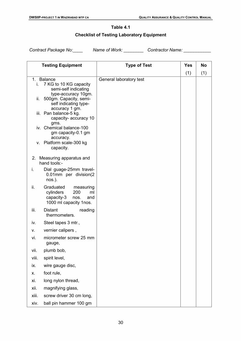
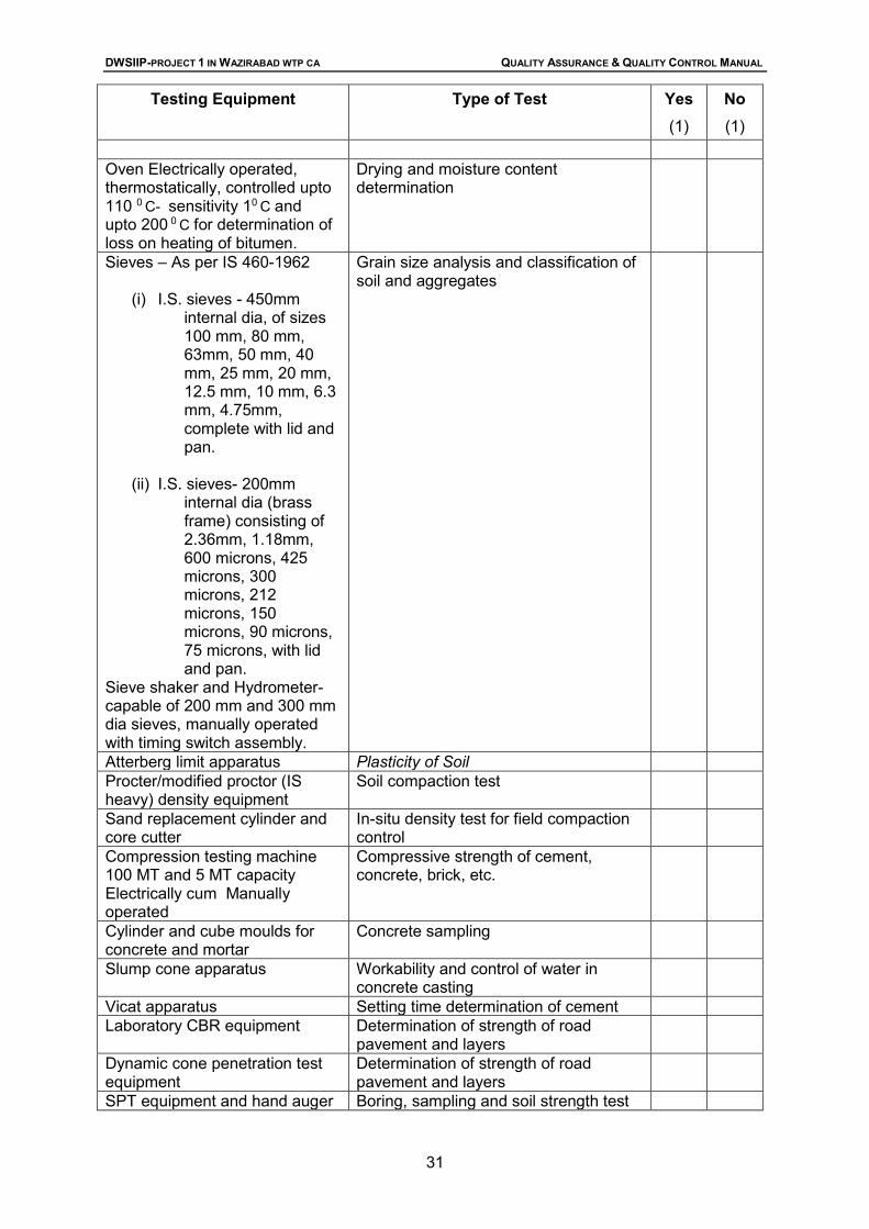
Table 4.1 Check List of Testing Laboratory Equipment
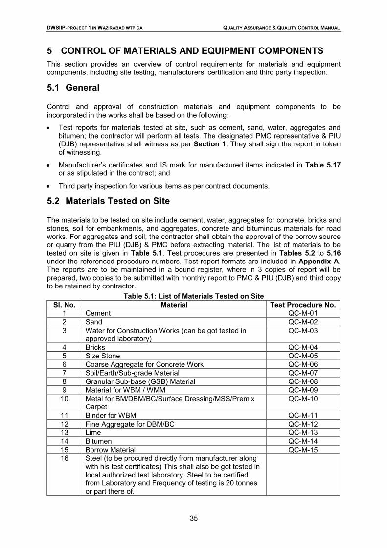
Table 5.1 List of materials Tested on Site
Table 5.2 Procedures for Testing Materials on Site: Cement
Table 5.3 Procedures for Testing Materials on Site: Sand
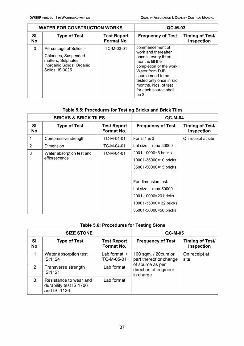
Table 5.4 Procedures for Testing Materials: Water for Construction works
Table 5.5 Procedures for Testing Materials: Bricks and Brick Tiles
Table 5.6 Procedures for Testing Materials: Stone
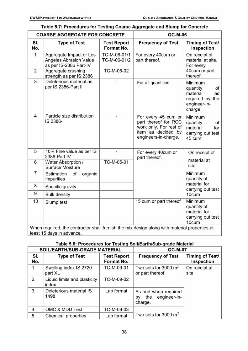
Table 5.7 Procedures for Testing Materials: Coarse Aggregate for Concrete
Table 5.8 Procedures for Testing Materials: Soil/Earth/Sub grade Material
Table 5.9 Procedures for Testing Materials: Granular Sub-base Material
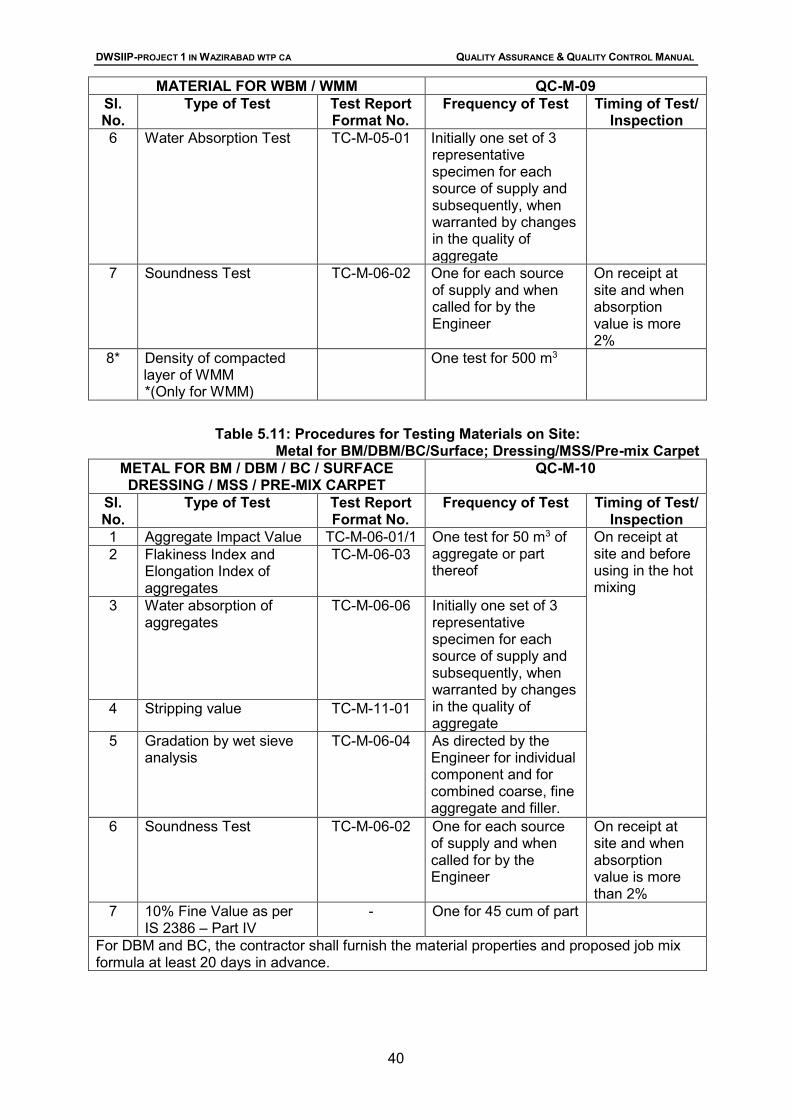
Table 5.10 Procedures for Testing Materials: for WBM / WMM
Table 5.11 Procedures for Testing Materials: Metal for BM/DBM/BC/Surface
Drawing / MSS /pre-mix Carpet.
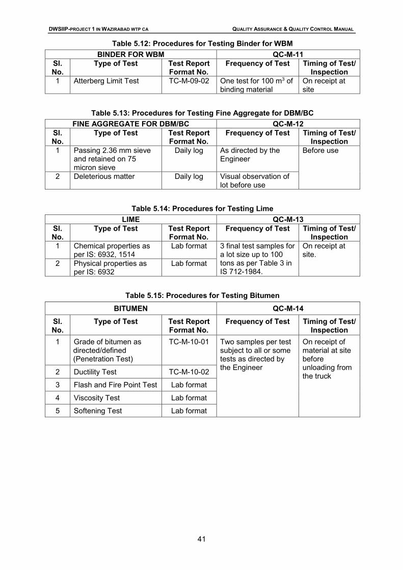
Table 5.12 Procedures for Testing Materials: Binder for WBM
Table 5.13 Procedures for Testing Materials: Aggregate for DBM / BC
Table 5.14 Procedures for Testing Materials: Lime
Table 5.15 Procedures for Testing Materials: Bitumen
Table 5.16 Procedures for Testing Materials: Borrow Material
Table 5.17 List of Materials and Equipment Certified by Manufacturer.
Table 5.18 List of Materials and Equipment Inspected by Third Party
Table 6.1 List of Tests for Cement Civil and Structural Works
Table 6.2 Procedures for Testing Embankment Formation
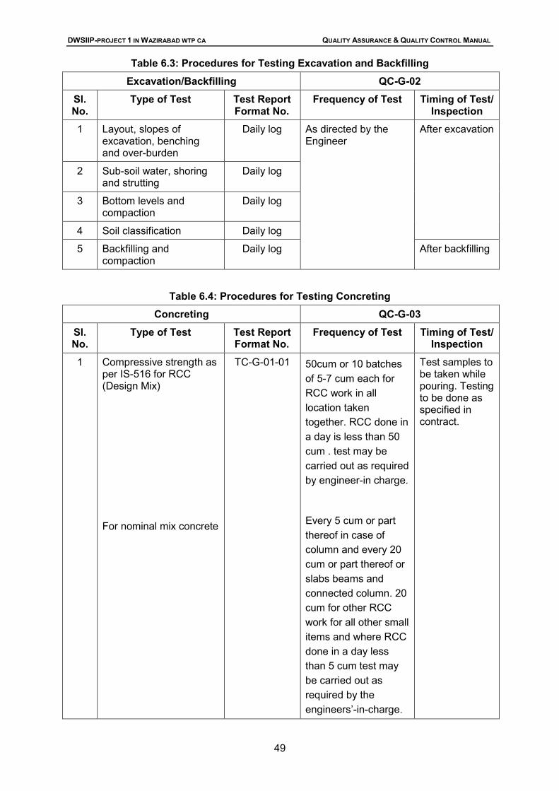
Table 6.3 Procedures for Testing Excavation and Backfilling
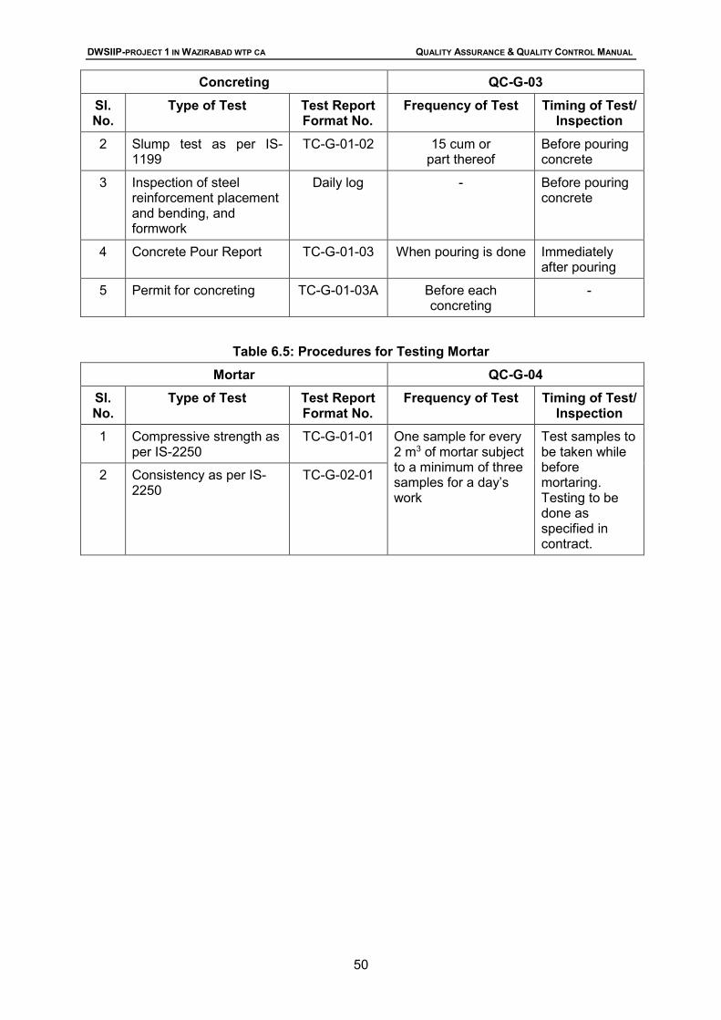
Table 6.4 Procedures for Testing Concreting
Table 6.5 Procedures for Testing Mortar
Table 7.1 List of Tests for Pipeline works and Liquid Retaining Structures
Table 7.2 Procedures for Testing Mortar
Table 7.3 Procedures for Testing Completion of Pipe Laying and Jointing
Table 7.4 Procedures for Testing Manhole / Valve Chamber
Table 7.5 Procedures for Testing Liquid Retaining Structures
Table 9.1 List of Tests for Road Works
Table 9.2 Procedures for Testing Road Embankment Formation
Table 9.3 Procedures for Testing Road Excavation
Table 9.4 Procedures for Testing Road Granular Sub-base Laying
DWSIIP-PROJECT 1 IN WAZIRABAD WTP CA QUALITY ASSURANCE & QUALITY CONTROL MANUAL
(PAGE v)
Table 9.5 Procedures for Testing WBM Layer
Table 9.6 Procedures for Testing Prime Coat / Tack Coat application
Table 9.7 Procedures for Testing Surface Drawing / Mix Seal Surfacing/Pre-mix Carpet
Table 9.8 Procedures for Testing Bituminous Macadam Laying
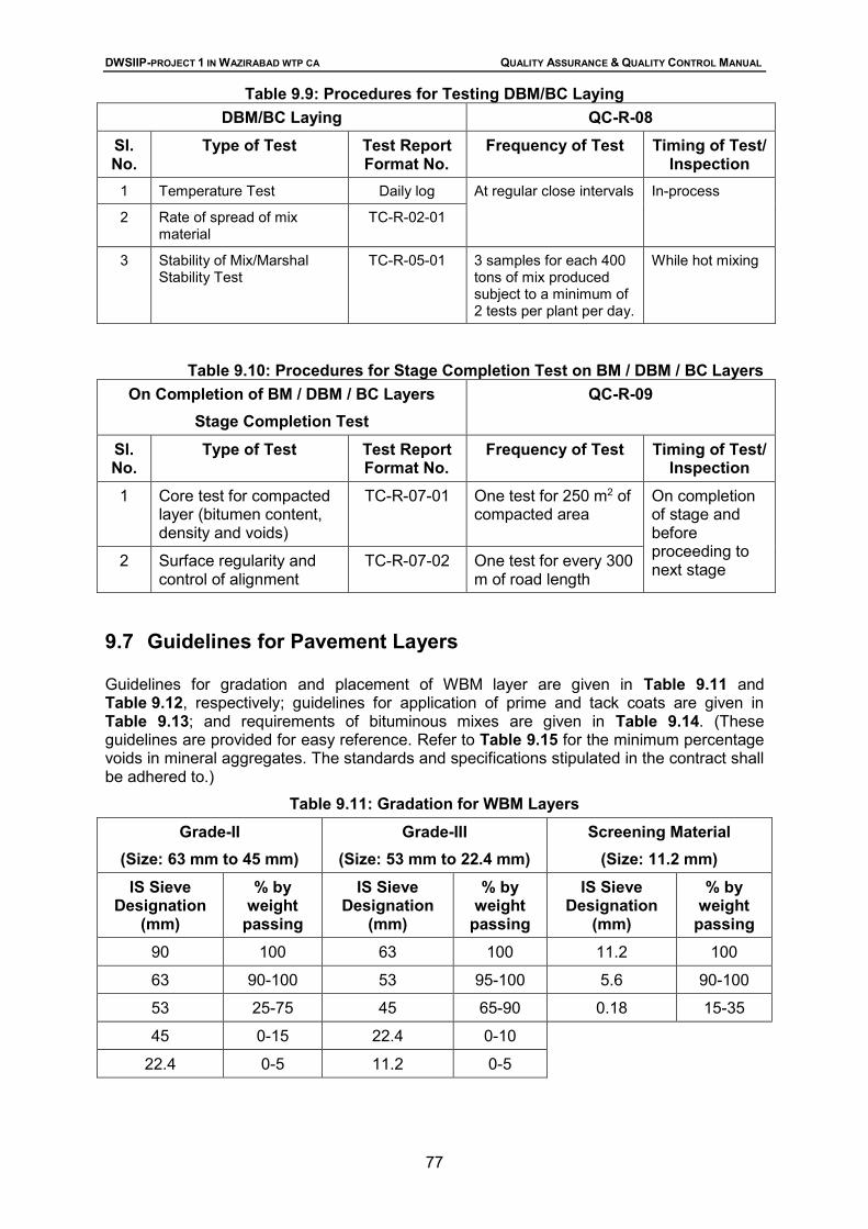
Table 9.9 Procedures for Testing DBM / BC Laying
Table 9.10 Procedures for Stage Completion Test on BM / DBM / BC Layers
Table 9.11 Gradation for WBM Layers
Table 9.12 Guidelines for Placement of WBM Layers
Table 9.13 Guidelines for Prime / Tack coat Application
Table 9.14 Requirements of Bituminous Mixes
Table 9.15 Minimum % Voids in Mineral Aggregate (VMA)
Table 9.16 Surface Level Tolerances
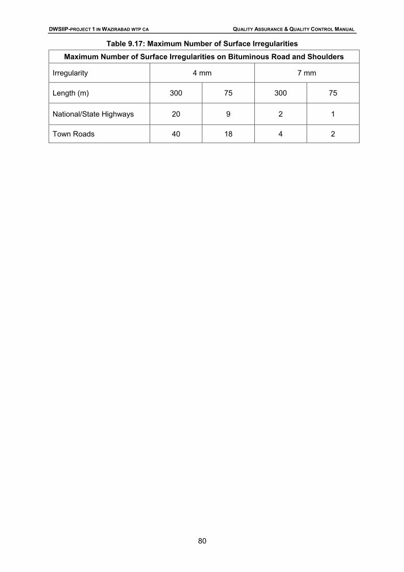
Table 9.17 Maximum Number of Surface Level Irregularities
List of Figures: Figure 3.1 Flow Chart for Document Control
Figure 3.2 Inspection Daily Report
Figure 3.3 Sample Weekly Report
Figure 3.4 Quantities Register
Figure 3.5 Sample Claim Forms as submitted by Contractor
Figure 3.6 Typical Variation Order
Figure 6.1 Process Chart for Plain Cement Concreting / RCC with Stages of inspection
Figure 6.2 Process Chart for Mortar with Stages of inspections
Figure 7.1 Checks for Material Used in Pipeline
Figure 7.2 Checks of Preparatory Works before Laying Water Supply age Pipelines
Figure 7.3 Process chart for Pipeline Works with Stages of Inspection
Figure 9.1 Flow Chart for the Construction of Embankment and Sub-grade
Figure 9.2 Flow Chart for the Construction of Granular Sub-base
Figure 9.3 Flow Chart for the Construction of WBM Layers
Figure 9.4 Flow Chart for the Construction of Application of primer / Tack coat
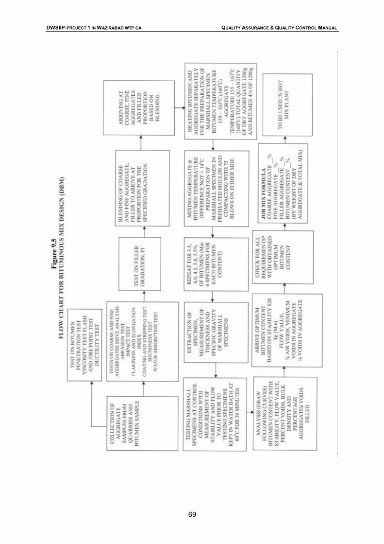
Figure 9.5 Flow Chart for the Construction for Bituminous Mix Design (DBM)
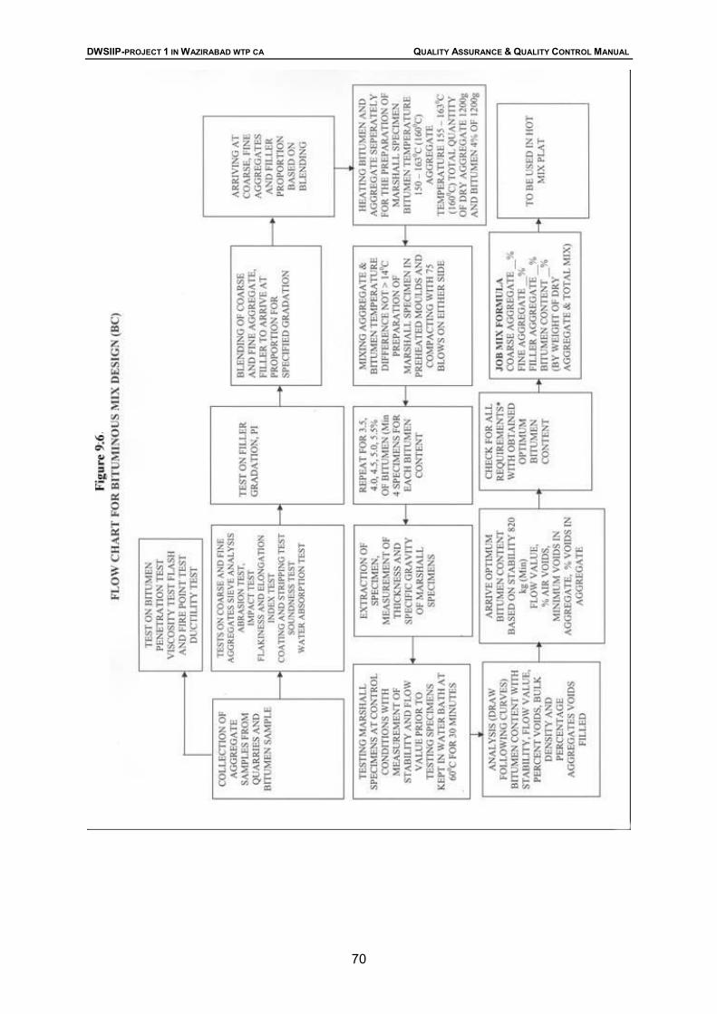
Figure 9.6 Flow Chart for the Construction for Bituminous Mix Design (BC)
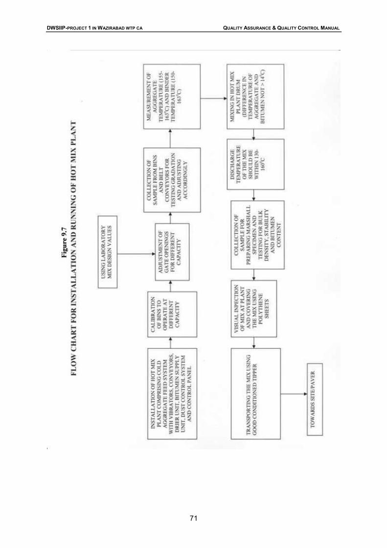
Figure 9.7 Flow Chart for the Construction for Installation and Running of Hot Mix Plant
Figure 9.8 Flow Chart for the Construction for Laying Profile Corrective Course
Figure 9.9 Flow Chart for the Construction of DBM/BC Layers
DWSIIP-PROJECT 1 IN WAZIRABAD WTP CA QUALITY ASSURANCE & QUALITY CONTROL MANUAL
(PAGE vi)
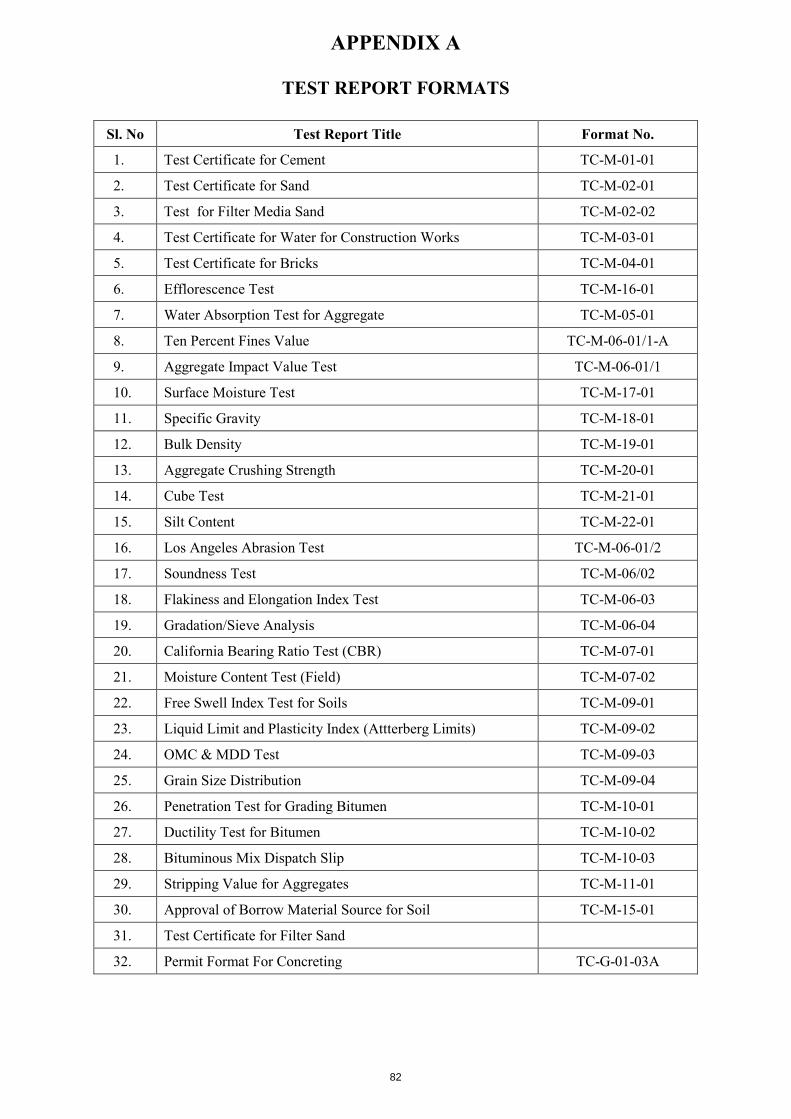
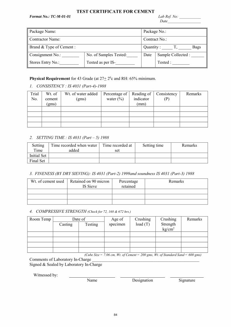
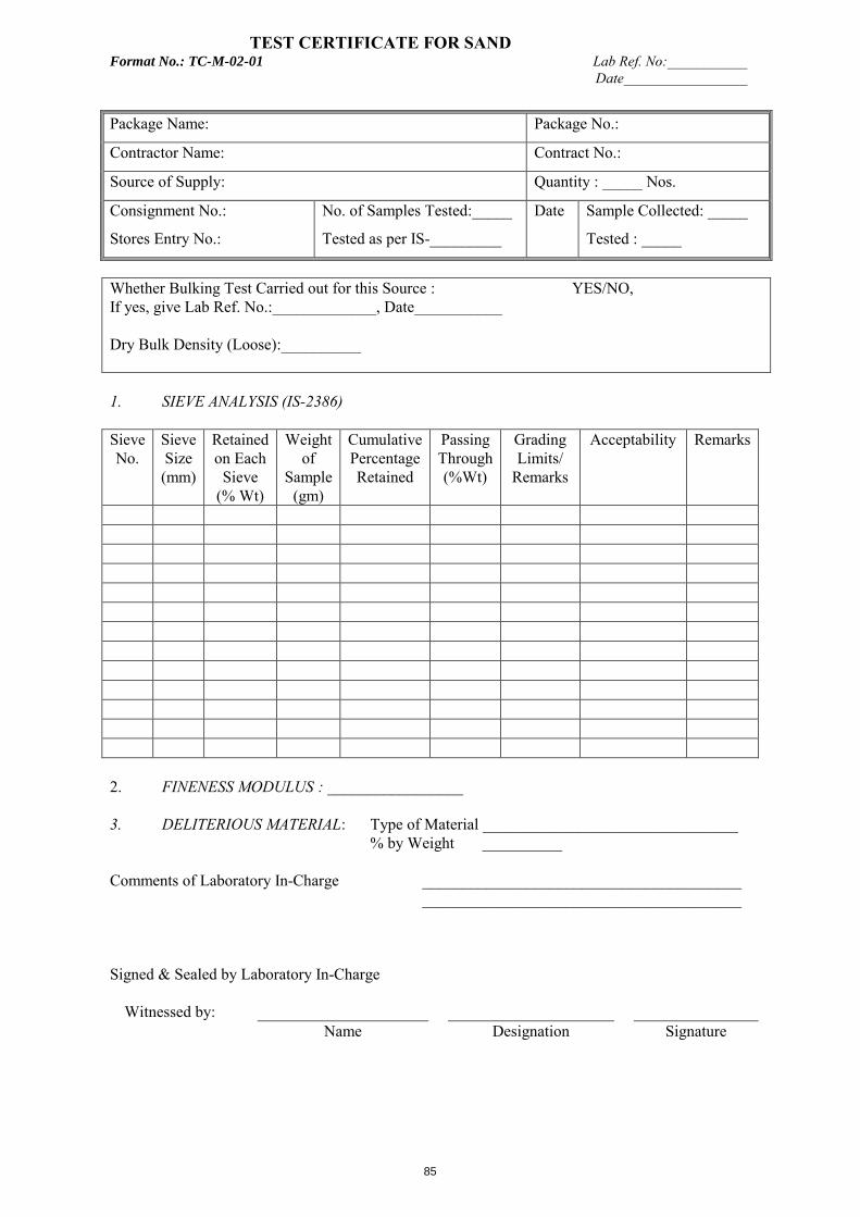
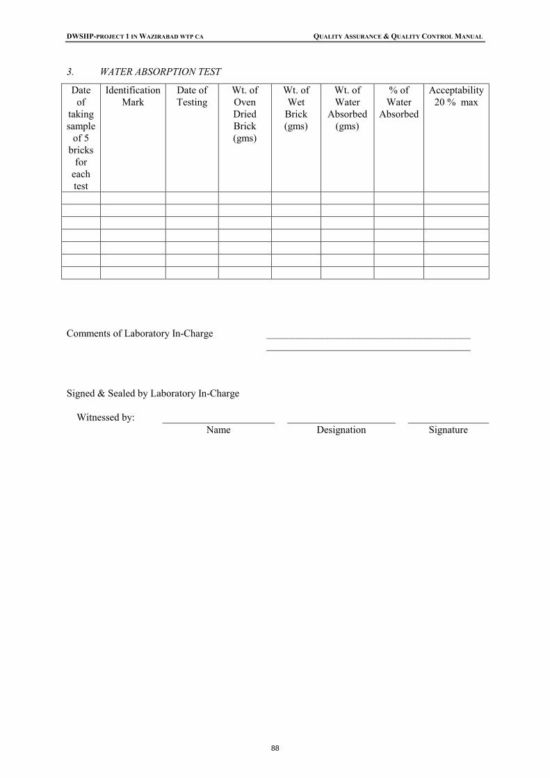
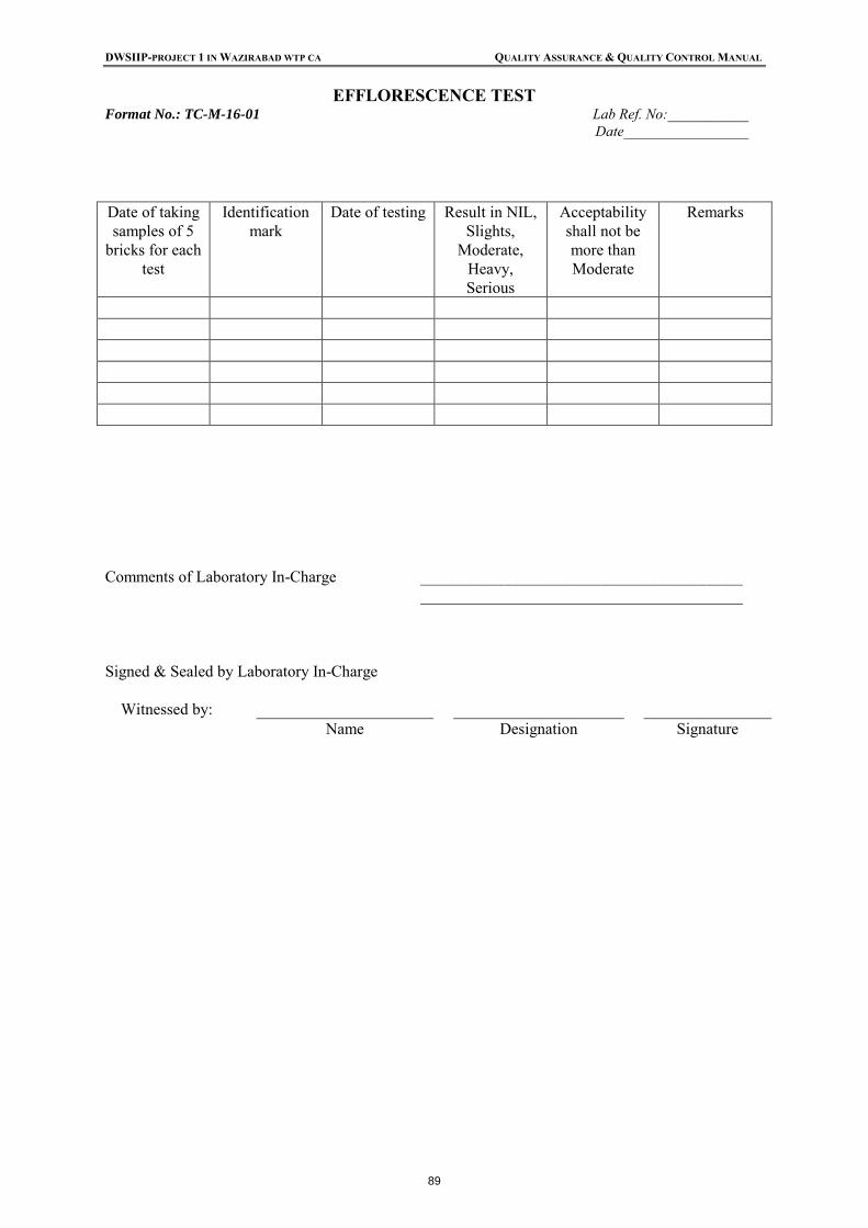
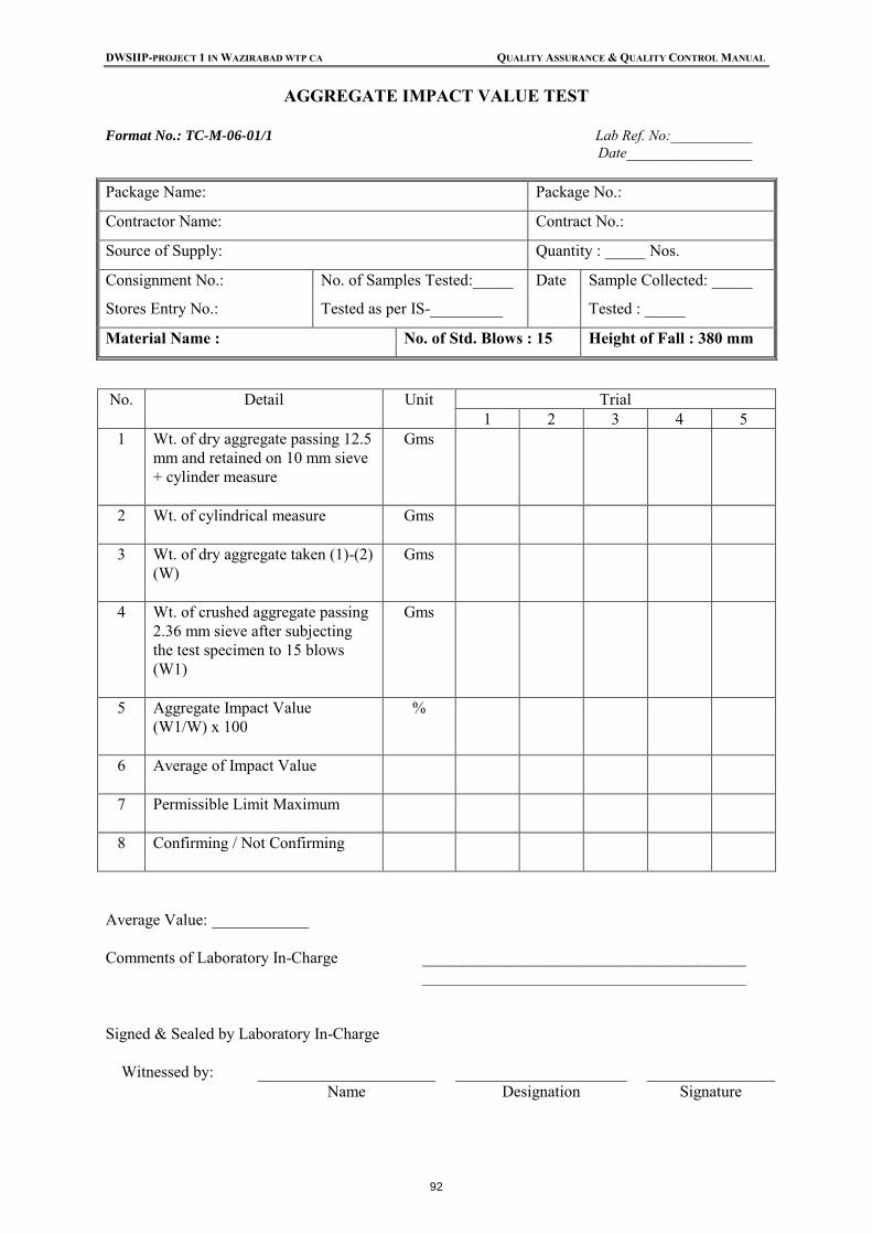
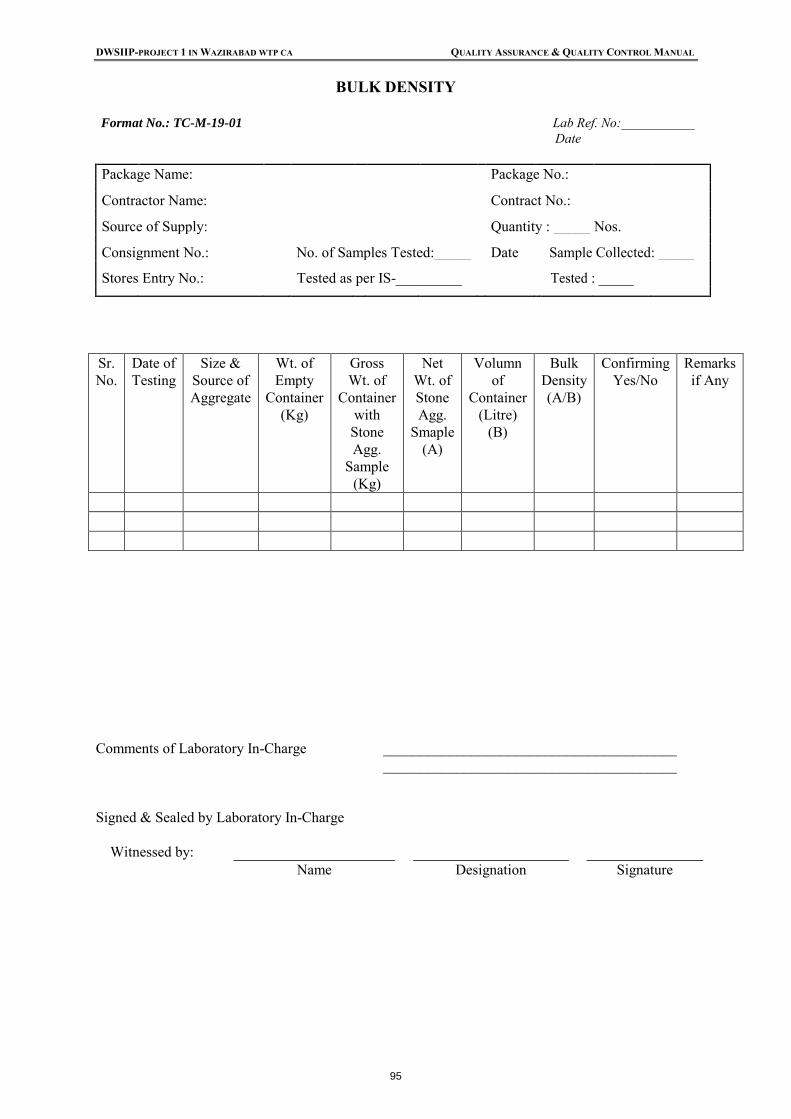
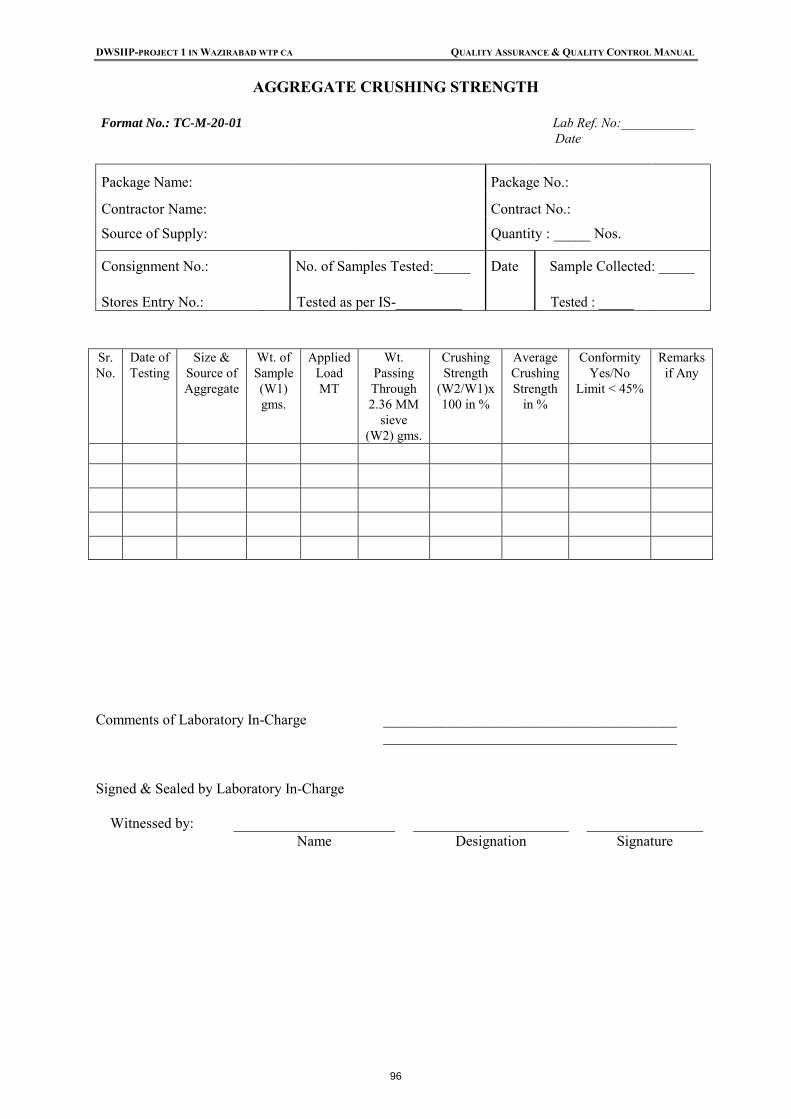
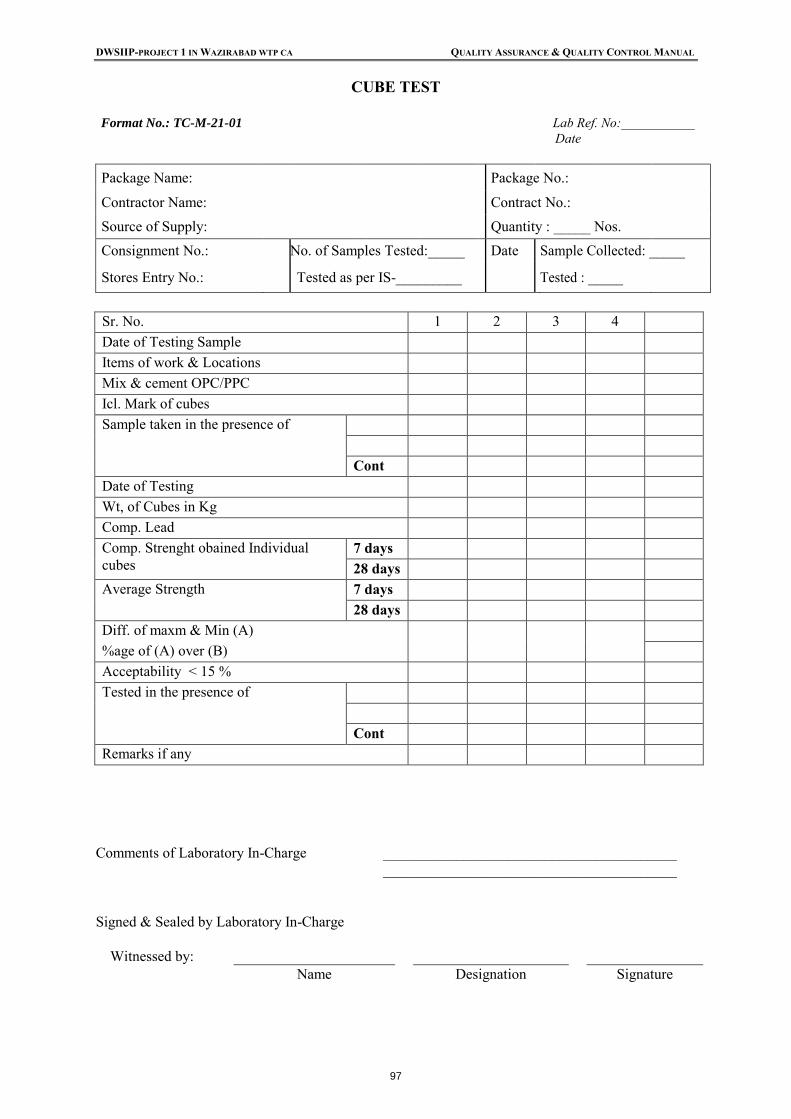
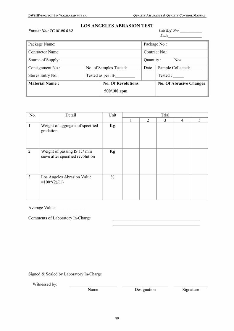
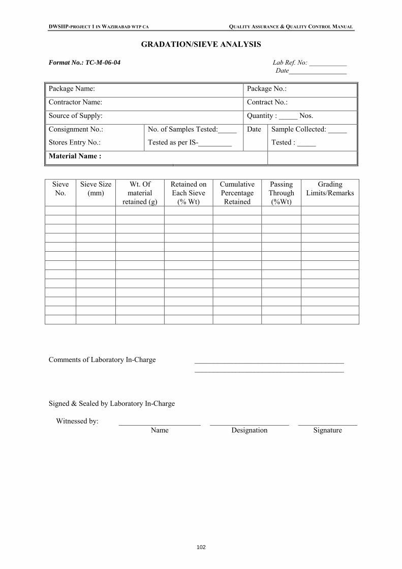
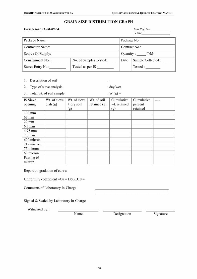
List of Appendices: Appendix-A: Test Report Formats:
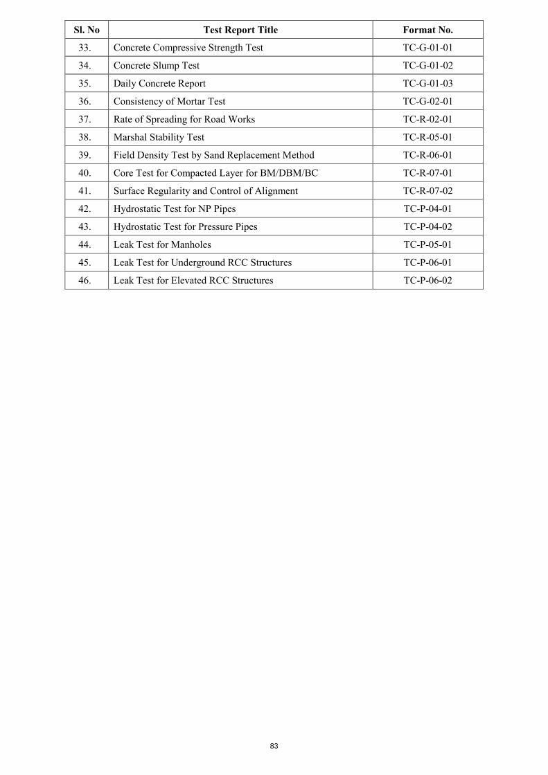
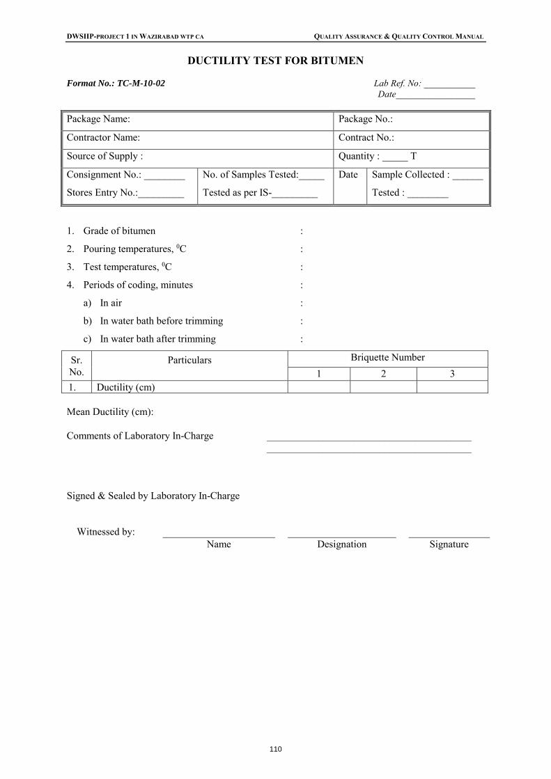
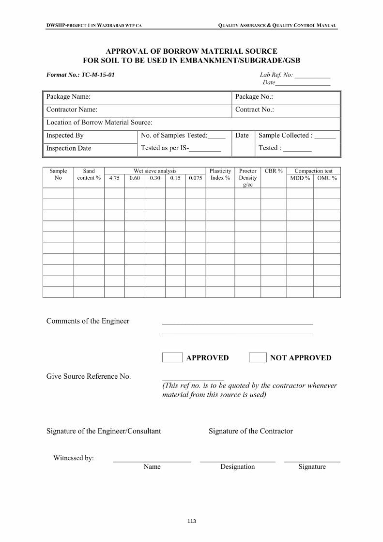
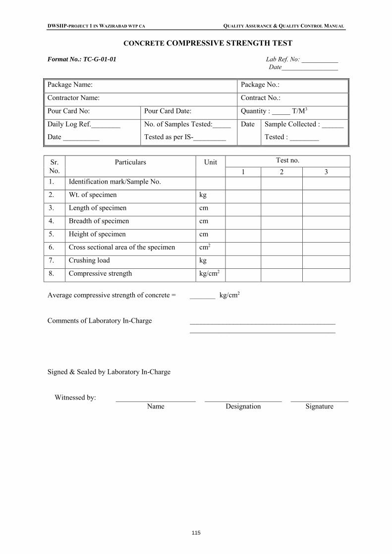
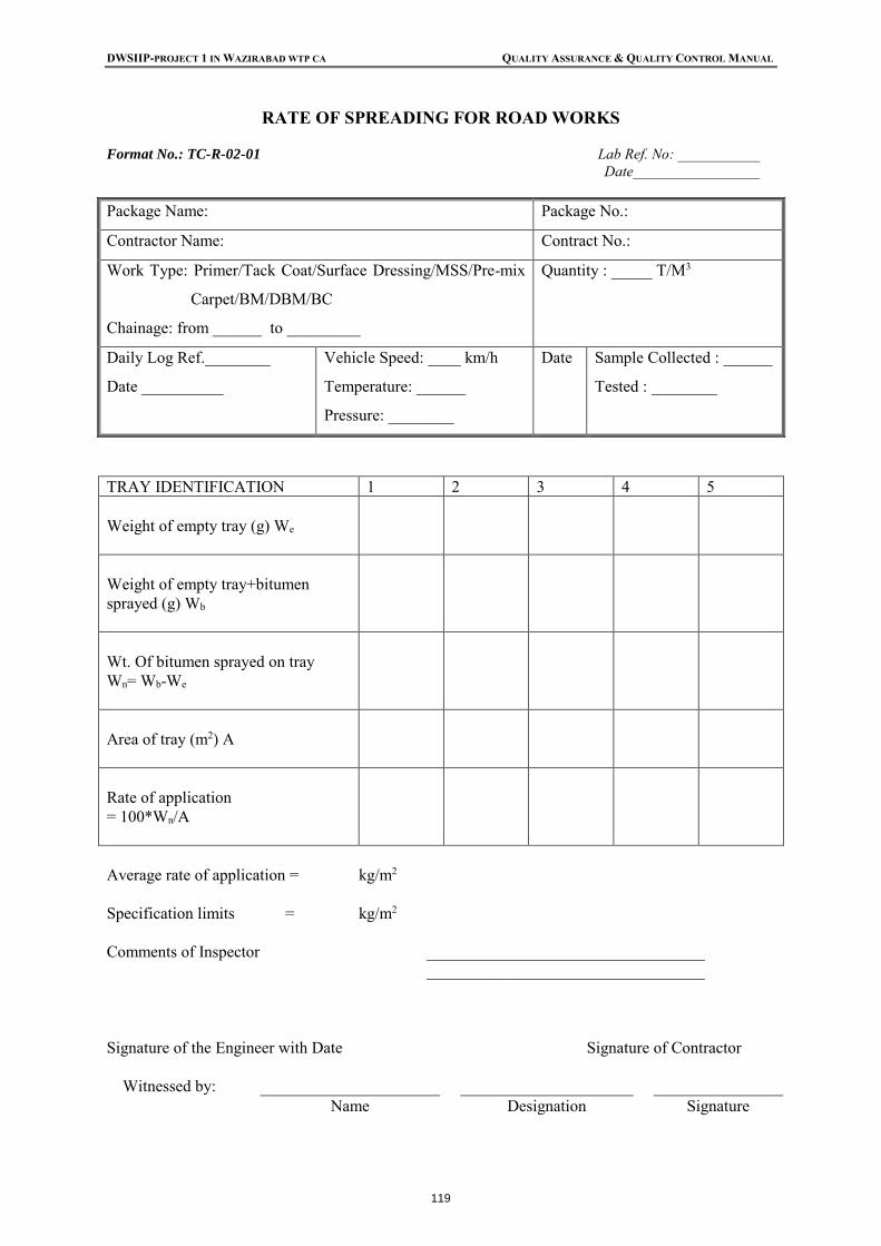
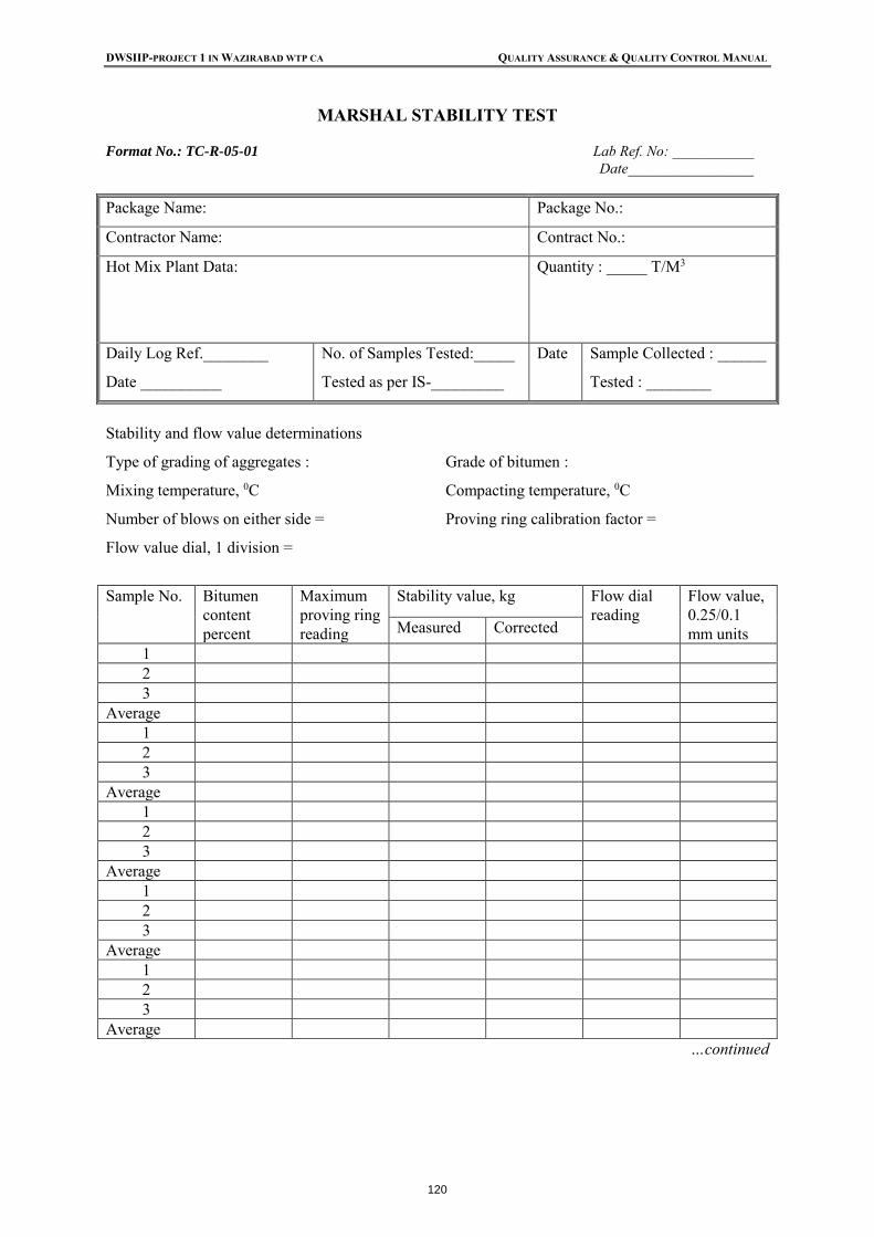
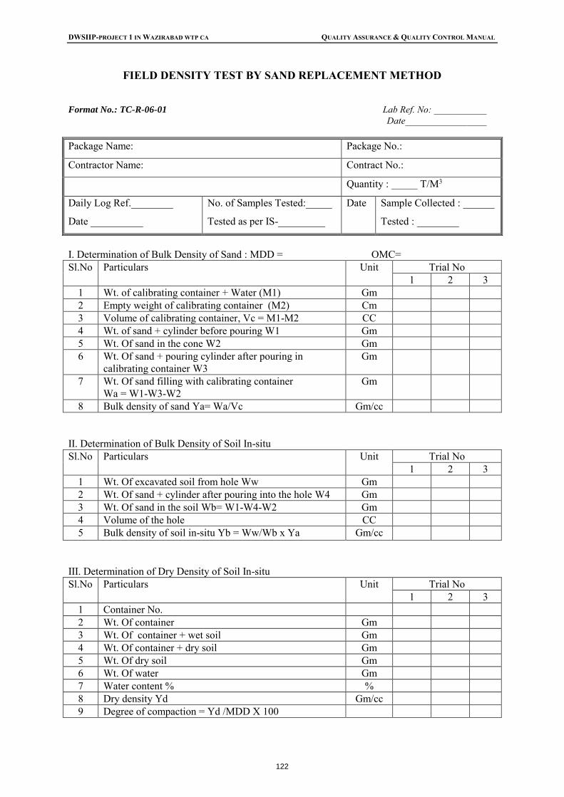
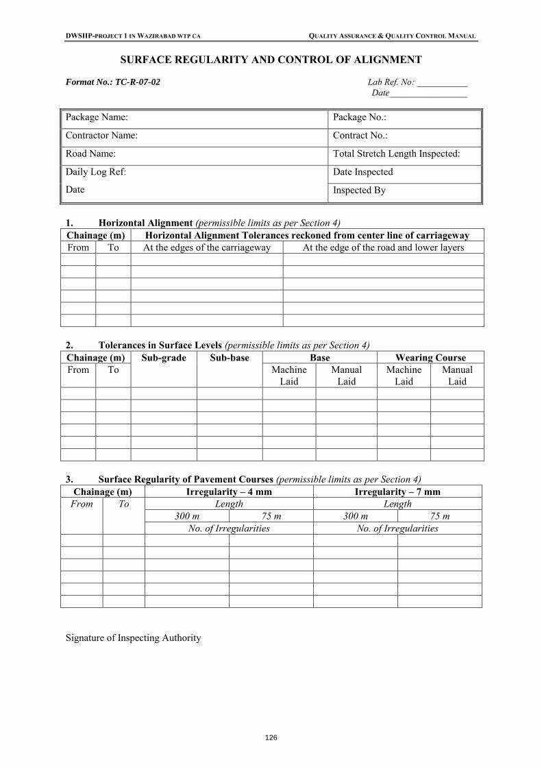
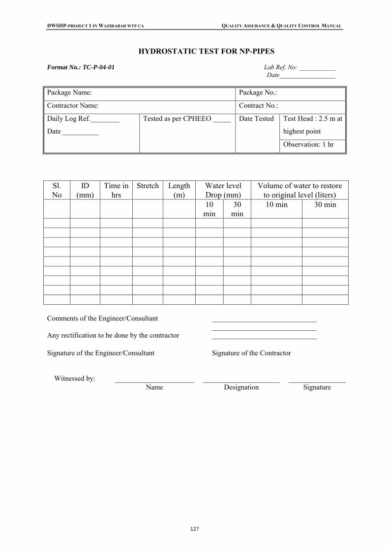
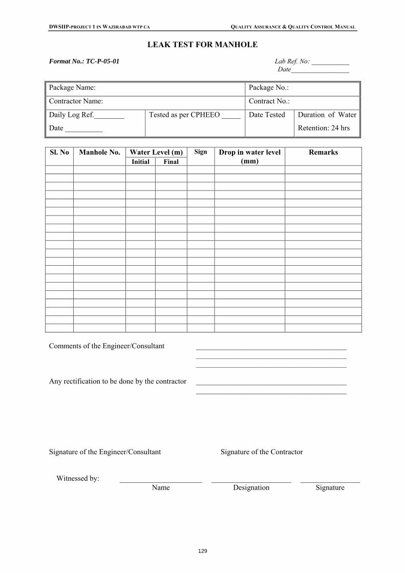
Test Certificate for Cement TC-M-01-01 Test Certificate for Sand TC-M-02-01 Test Certificate for Water for Construction Works TC-M-03-01 Test Certificate for Bricks TC-M-04-01 Efflorescence Test TC-M-16-01 Water Absorption Test for Aggregate TC-M-05-01 Ten Percent Fines Value TC-M-06-01/1-A Aggregate Impact Value Test TC-M-06-01/1 Surface Moisture Test TC-M-17-01 Specific Gravity TC-M-18-01 Bulk Density TC-M-19-01 Aggregate Crushing Strength TC-M-20-01 Cube Test TC-M-21-01 Silt Content TC-M-22-01 Los Angeles Abrasion Test TC-M-06-01/2 Soundness Test TC-M-06/02 Flakiness and Elongation Index Test TC-M-06-03 Gradation/Sieve Analysis TC-M-06-04 California Bearing Ratio Test (CBR) TC-M-07-01 Moisture Content Test (Field) TC-M-07-02 Free Swell Index Test for Soils TC-M-09-01 Liquid Limit and Plasticity Index (Attterberg Limits) TC-M-09-02 OMC & MDD Test TC-M-09-03 Grain Size Distribution TC-M-09-04 Penetration Test for Grading Bitumen TC-M-10-01 Ductility Test for Bitumen TC-M-10-02 Bituminous Mix Dispatch Slip TC-M-10-03 Stripping Value for Aggregates TC-M-11-01 Approval of Borrow Material Source for Soil TC-M-15-01 Permit Format for Concreting TC-G-01-03A Concrete Compressive Strength Test TC-G-01-01 Concrete Slump Test TC-G-01-02 Daily Concrete Report TC-G-01-03 Consistency of Mortar Test TC-G-02-01 Rate of Spreading for Road Works TC-R-02-01 Marshal Stability Test TC-R-05-01 Field Density Test by Sand Replacement Method TC-R-06-01 Core Test for Compacted Layer for BM/DBM/BC TC-R-07-01 Surface Regularity and Control of Alignment TC-R-07-02 Hydrostatic Test for NP Pipes TC-P-04-01 Hydrostatic Test for Pressure Pipes TC-P-04-02 Leak Test for Manholes TC-P-05-01 Leak Test for Underground RCC Structures TC-P-06-01
DWSIIP-PROJECT 1 IN WAZIRABAD WTP CA QUALITY ASSURANCE & QUALITY CONTROL MANUAL
(PAGE vii)
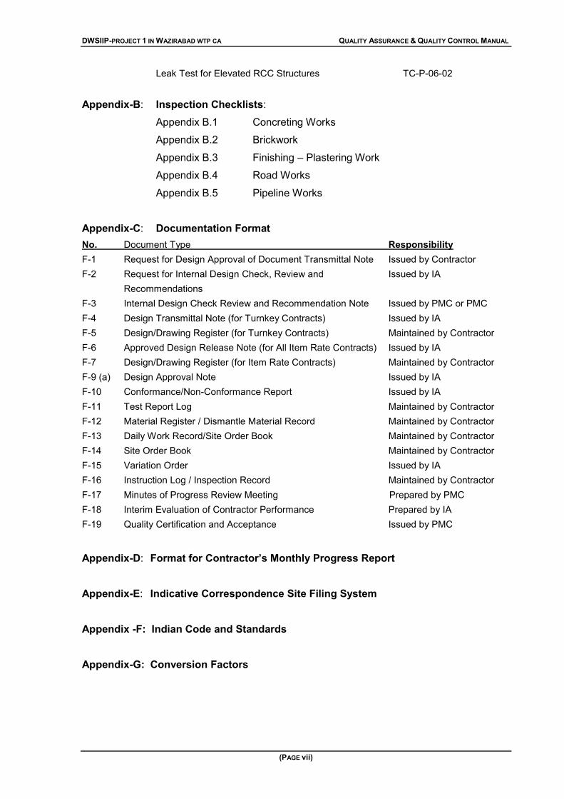
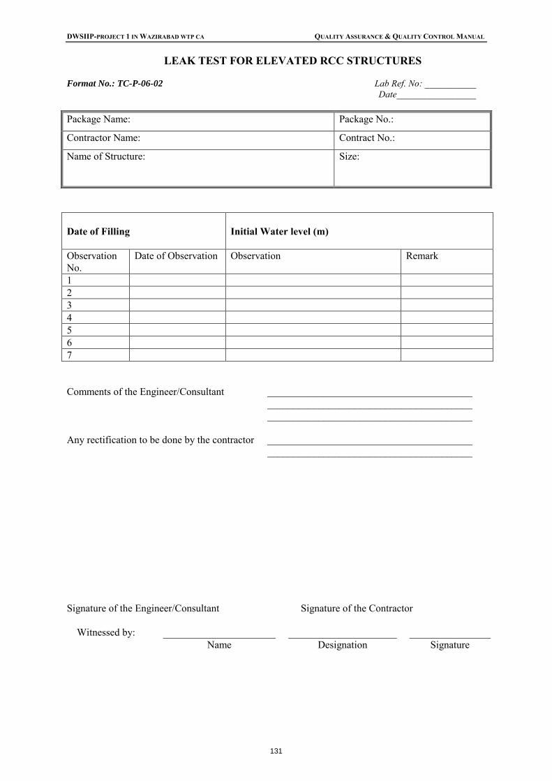
Leak Test for Elevated RCC Structures TC-P-06-02
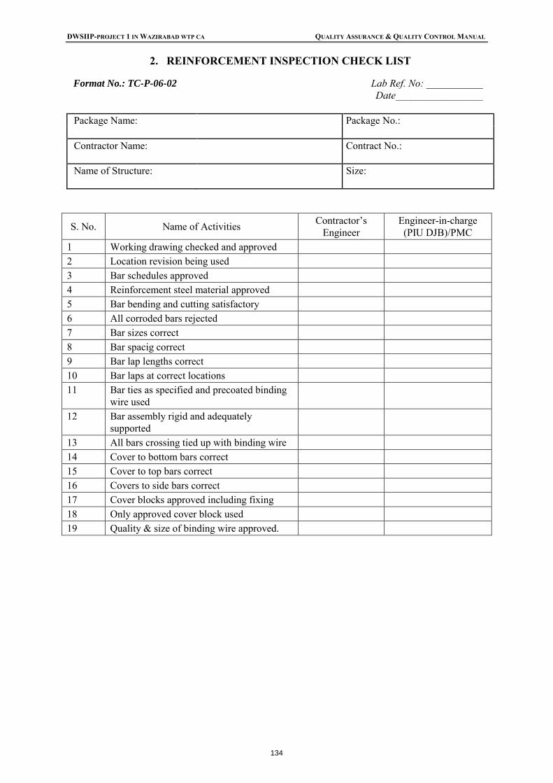
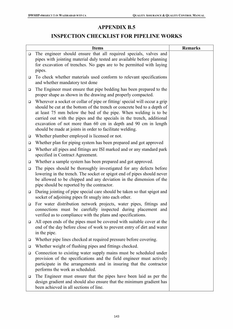
Appendix-B: Inspection Checklists: Appendix B.1 Concreting Works Appendix B.2 Brickwork Appendix B.3 Finishing – Plastering Work Appendix B.4 Road Works Appendix B.5 Pipeline Works
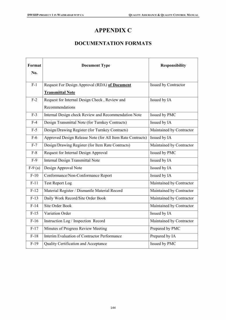
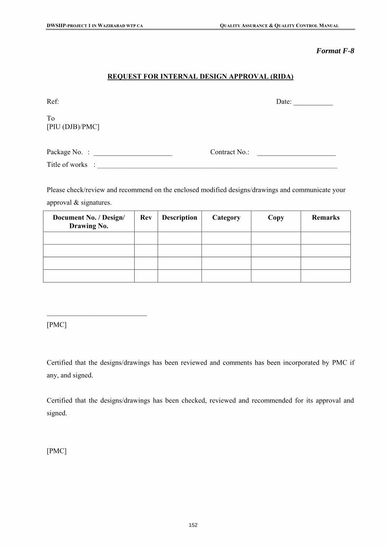
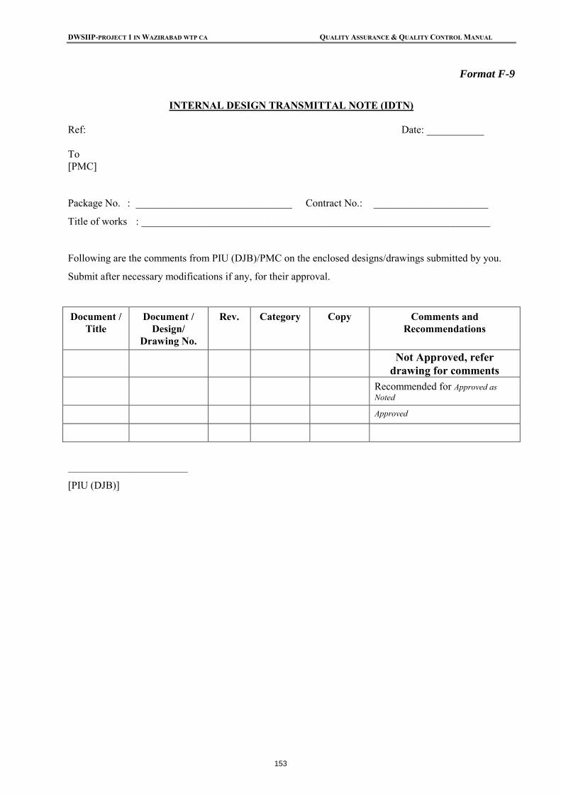
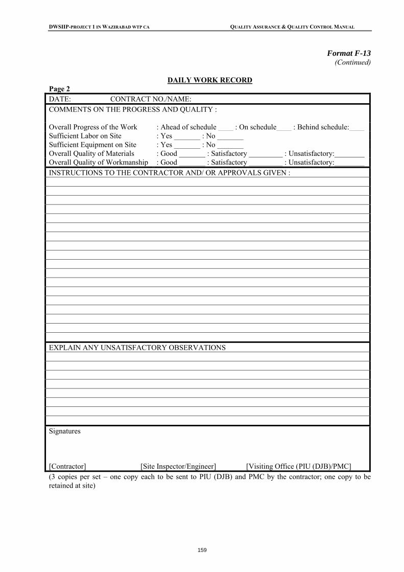
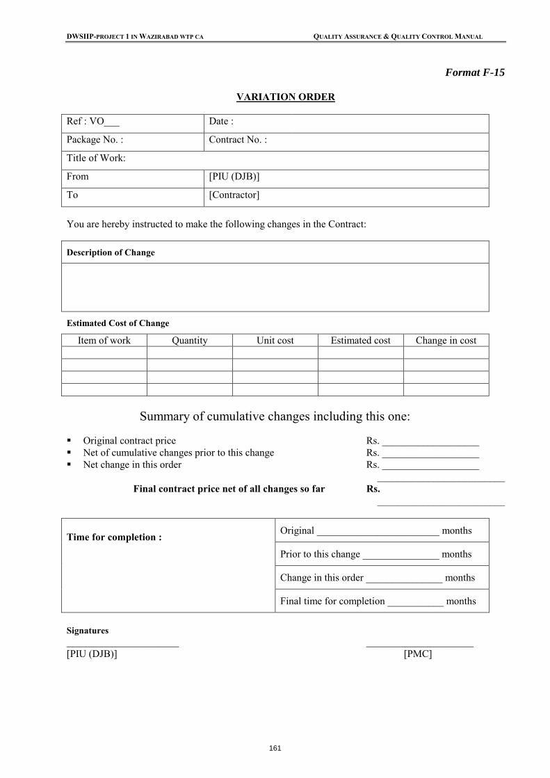
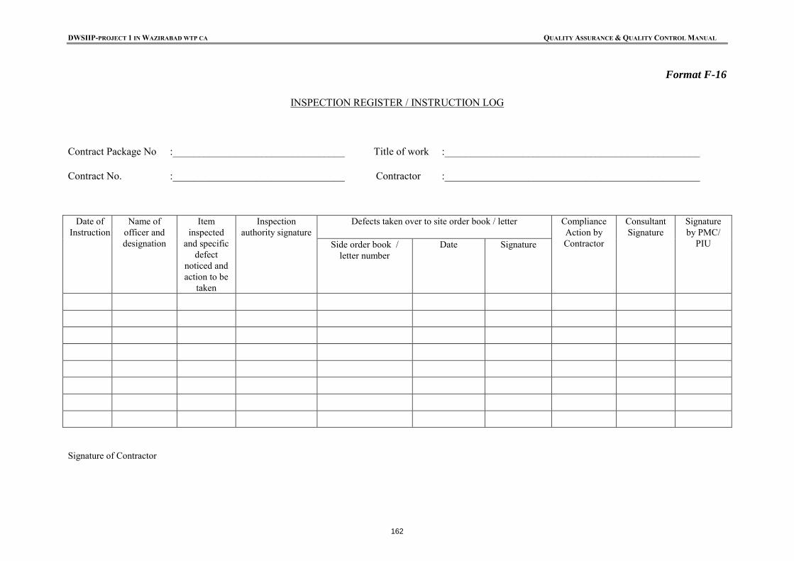
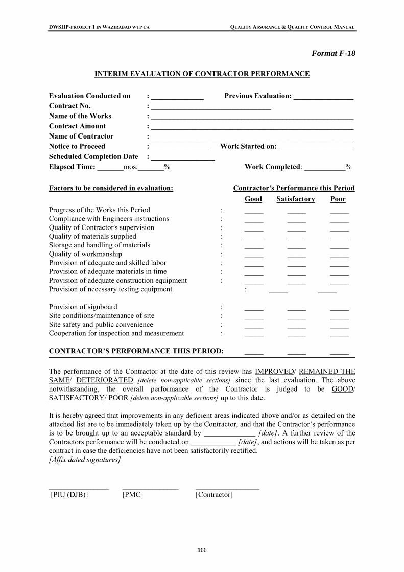
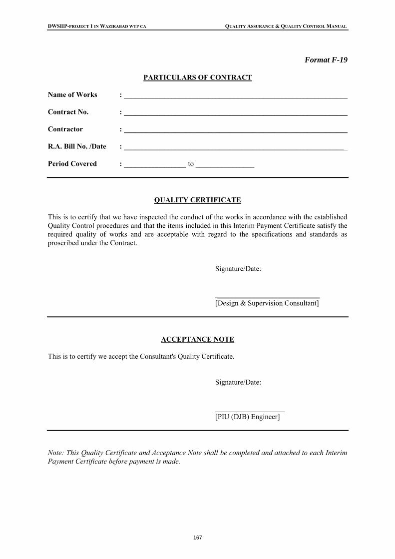
Appendix-C: Documentation Format No. Document Type Responsibility F-1 Request for Design Approval of Document Transmittal Note Issued by Contractor F-2 Request for Internal Design Check, Review and Issued by IA Recommendations F-3 Internal Design Check Review and Recommendation Note Issued by PMC or PMC F-4 Design Transmittal Note (for Turnkey Contracts) Issued by IA F-5 Design/Drawing Register (for Turnkey Contracts) Maintained by Contractor F-6 Approved Design Release Note (for All Item Rate Contracts) Issued by IA F-7 Design/Drawing Register (for Item Rate Contracts) Maintained by Contractor F-9 (a) Design Approval Note Issued by IA F-10 Conformance/Non-Conformance Report Issued by IA F-11 Test Report Log Maintained by Contractor F-12 Material Register / Dismantle Material Record Maintained by Contractor F-13 Daily Work Record/Site Order Book Maintained by Contractor F-14 Site Order Book Maintained by Contractor F-15 Variation Order Issued by IA F-16 Instruction Log / Inspection Record Maintained by Contractor F-17 Minutes of Progress Review Meeting Prepared by PMC F-18 Interim Evaluation of Contractor Performance Prepared by IA F-19 Quality Certification and Acceptance Issued by PMC
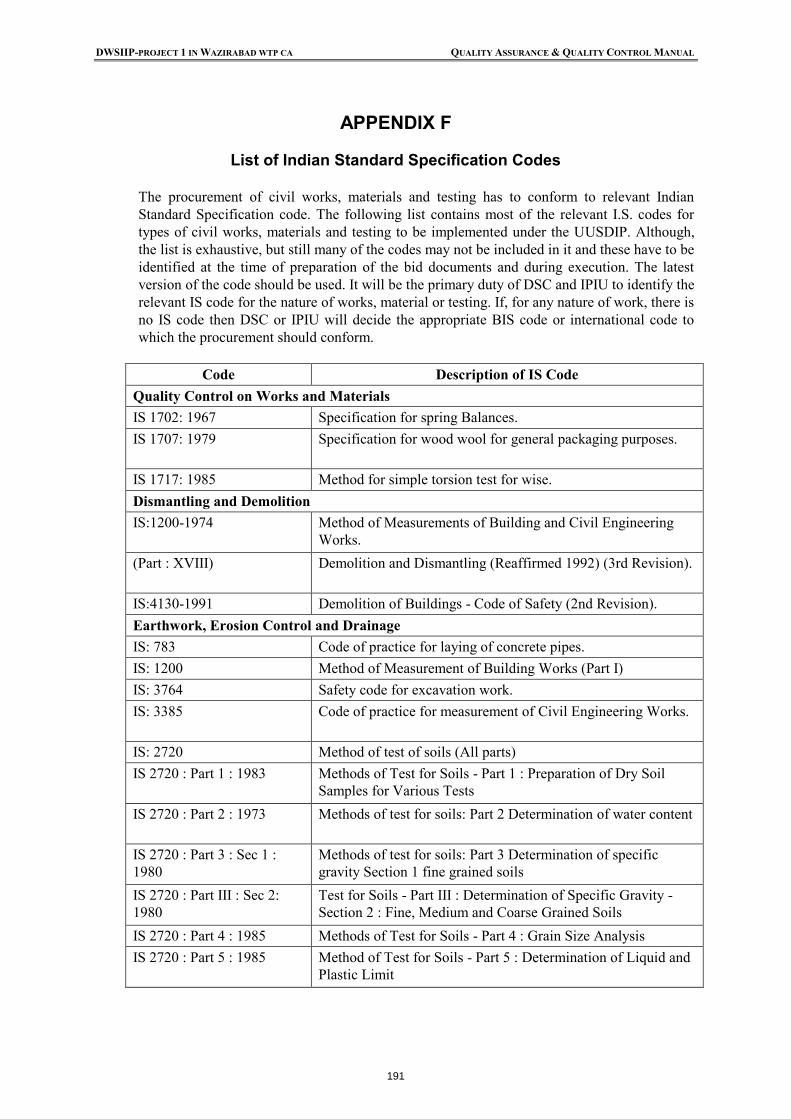
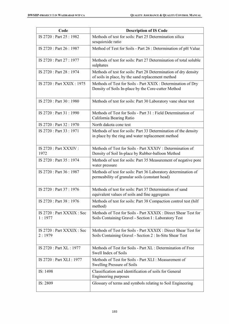
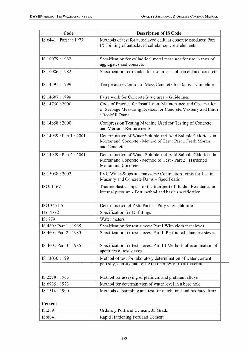
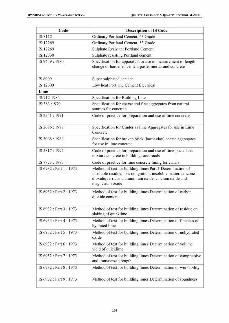
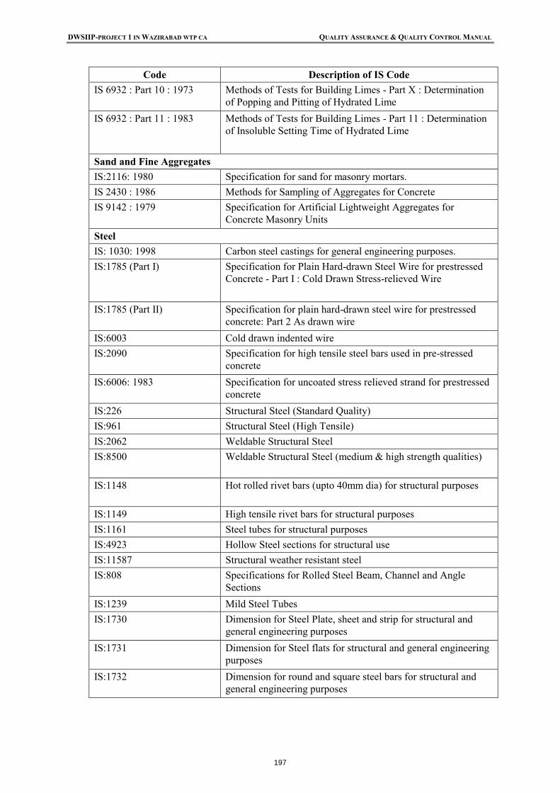
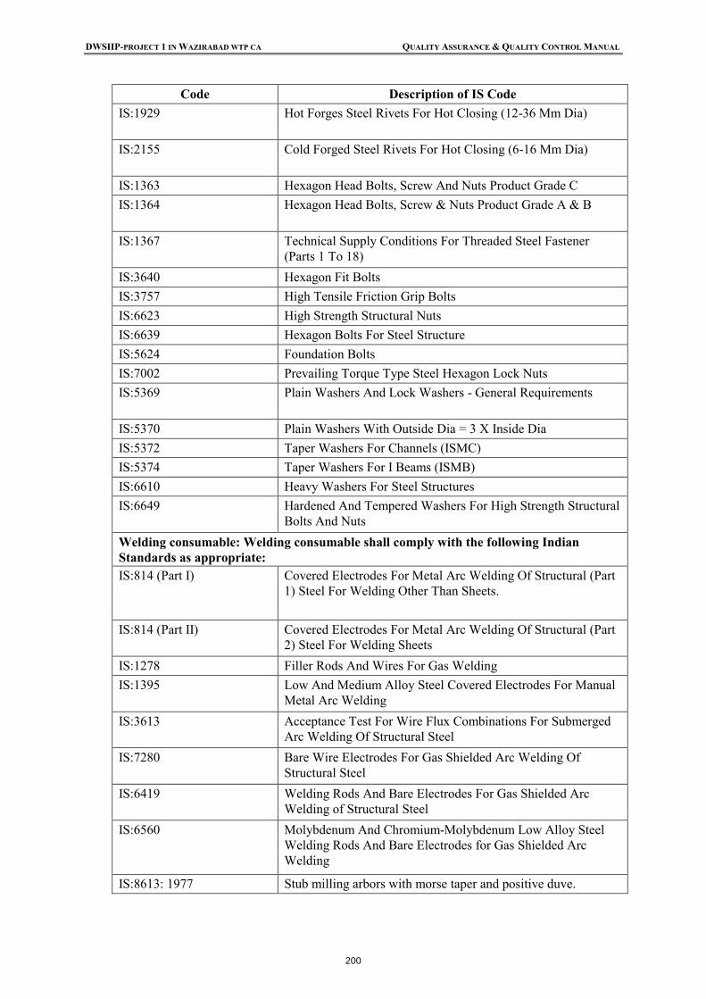
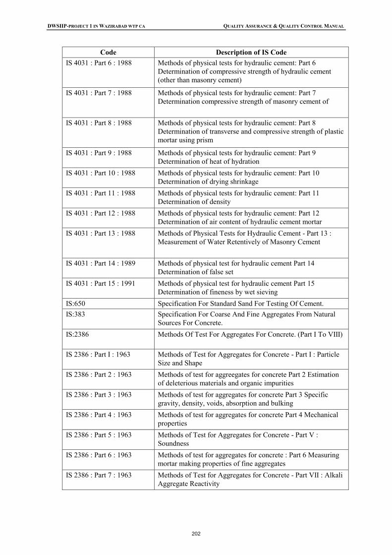
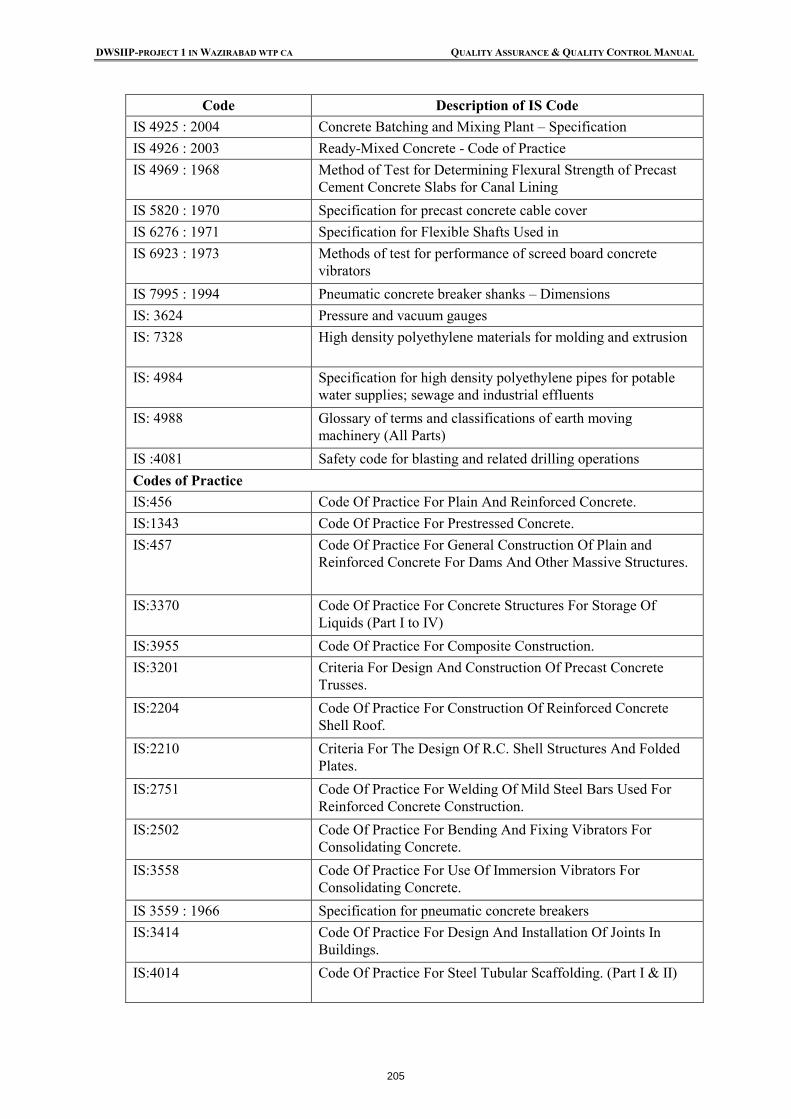
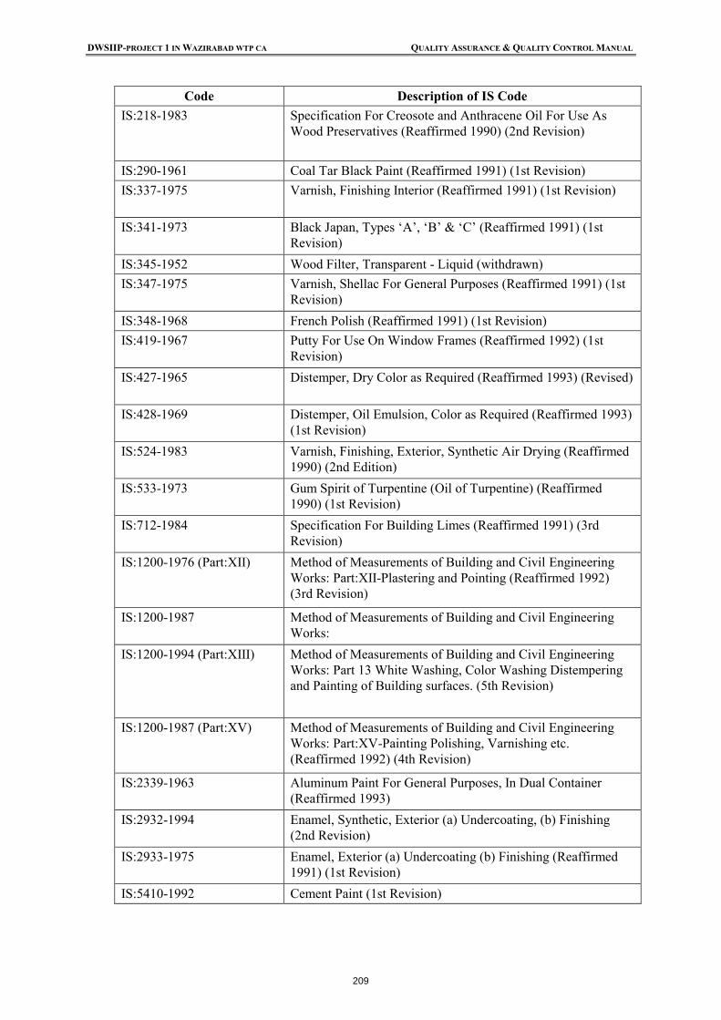
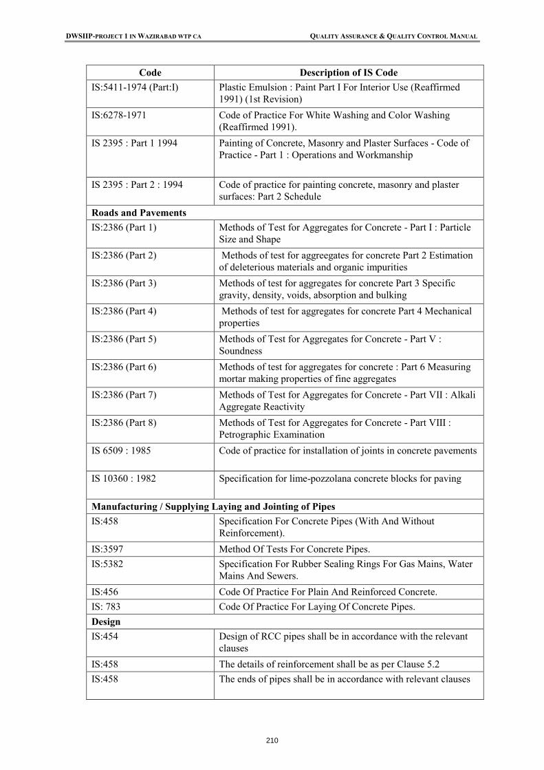
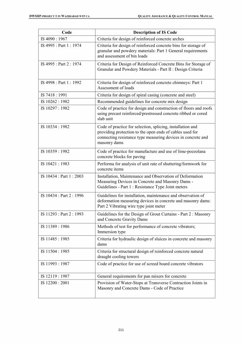
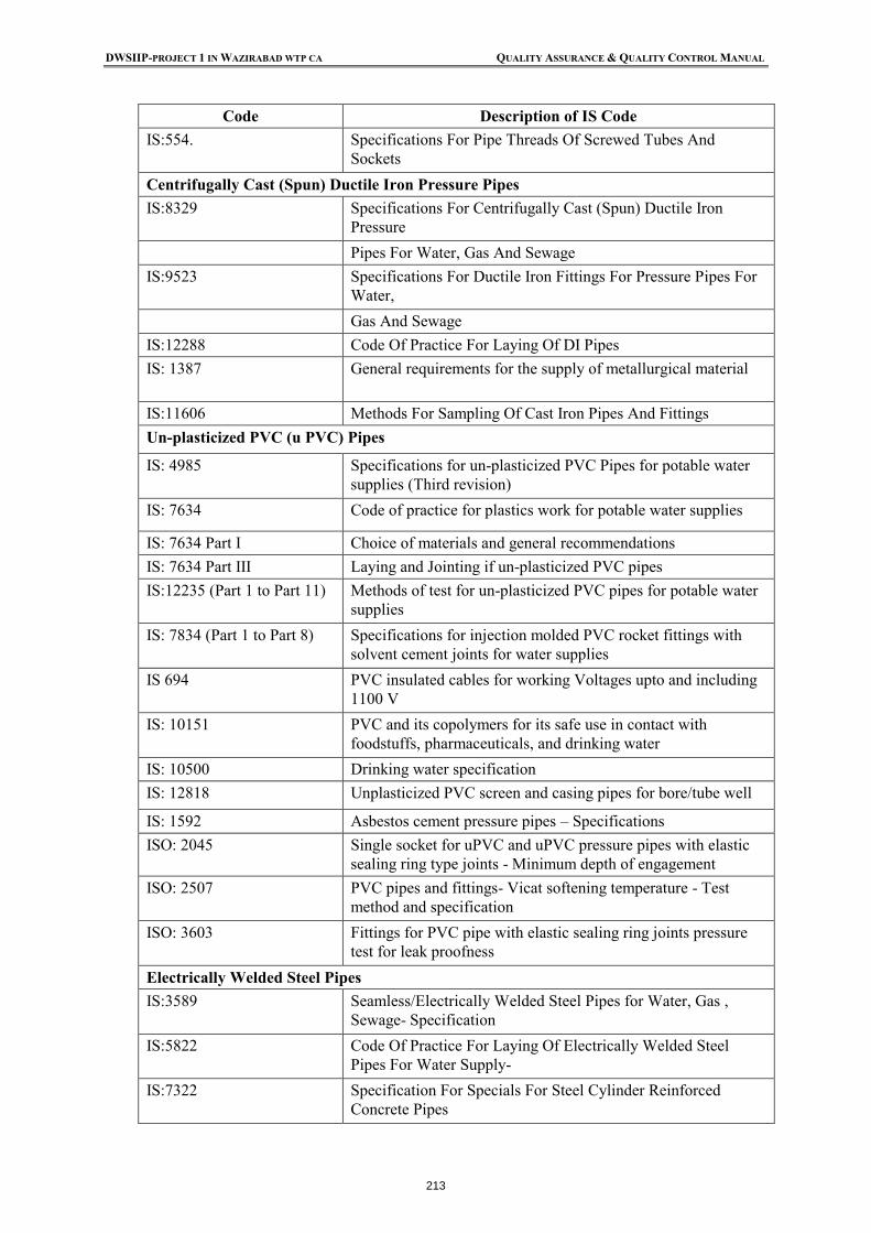
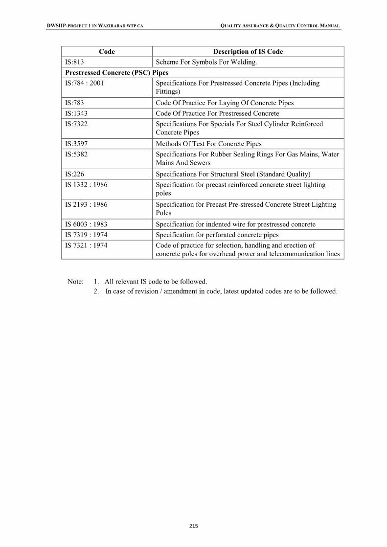
Appendix-D: Format for Contractor’s Monthly Progress Report Appendix-E: Indicative Correspondence Site Filing System Appendix -F: Indian Code and Standards Appendix-G: Conversion Factors
DWSIIP-PROJECT 1 IN WAZIRABAD WTP CA QUALITY ASSURANCE & QUALITY CONTROL MANUAL
1
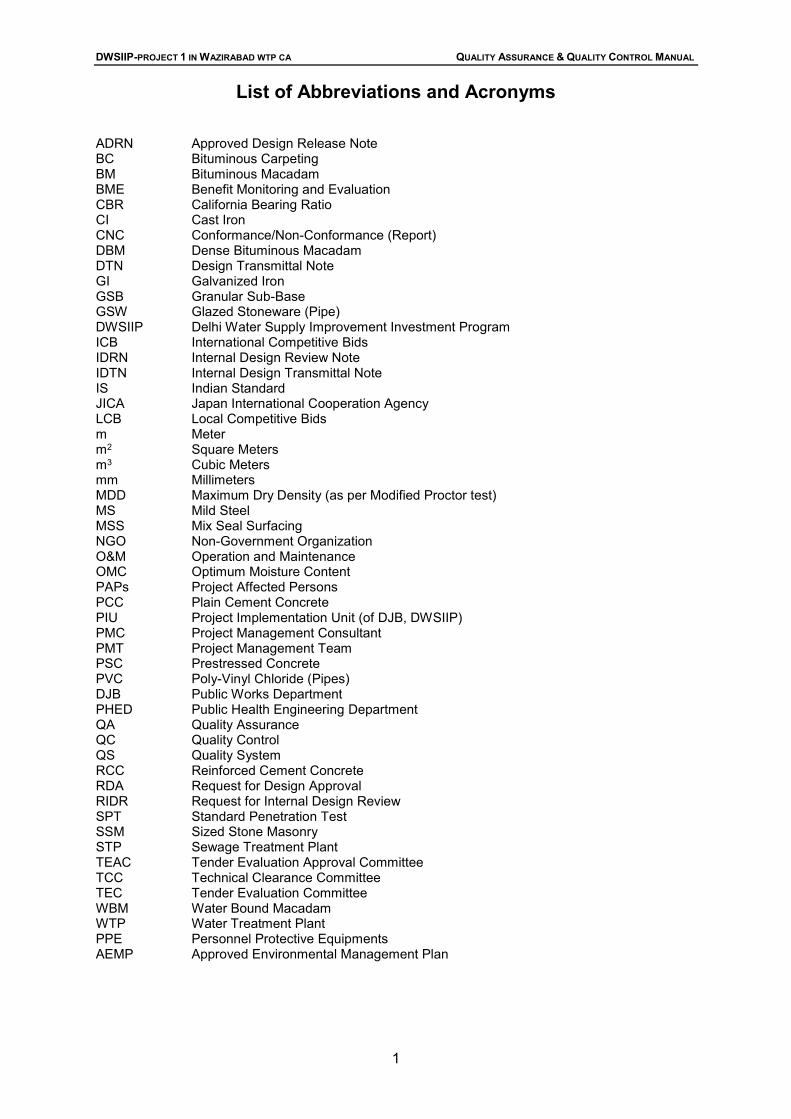
List of Abbreviations and Acronyms
ADRN Approved Design Release Note BC Bituminous Carpeting BM Bituminous Macadam BME Benefit Monitoring and Evaluation CBR California Bearing Ratio CI Cast Iron CNC Conformance/Non-Conformance (Report) DBM Dense Bituminous Macadam DTN Design Transmittal Note GI Galvanized Iron GSB Granular Sub-Base GSW Glazed Stoneware (Pipe) DWSIIP Delhi Water Supply Improvement Investment Program ICB International Competitive Bids IDRN Internal Design Review Note IDTN Internal Design Transmittal Note IS Indian Standard JICA Japan International Cooperation Agency LCB Local Competitive Bids m Meter m2 Square Meters m3 Cubic Meters mm Millimeters MDD Maximum Dry Density (as per Modified Proctor test) MS Mild Steel MSS Mix Seal Surfacing NGO Non-Government Organization O&M Operation and Maintenance OMC Optimum Moisture Content PAPs Project Affected Persons PCC Plain Cement Concrete PIU Project Implementation Unit (of DJB, DWSIIP) PMC Project Management Consultant PMT Project Management Team PSC Prestressed Concrete PVC Poly-Vinyl Chloride (Pipes) DJB Public Works Department PHED Public Health Engineering Department QA Quality Assurance QC Quality Control QS Quality System RCC Reinforced Cement Concrete RDA Request for Design Approval RIDR Request for Internal Design Review SPT Standard Penetration Test SSM Sized Stone Masonry STP Sewage Treatment Plant TEAC Tender Evaluation Approval Committee TCC Technical Clearance Committee TEC Tender Evaluation Committee WBM Water Bound Macadam WTP Water Treatment Plant PPE Personnel Protective Equipments AEMP Approved Environmental Management Plan
DWSIIP-PROJECT 1 IN WAZIRABAD WTP CA QUALITY ASSURANCE & QUALITY CONTROL MANUAL
2
PREFACE This Quality Assurance /Quality Control Manual has been prepared with the objective of putting in place a comprehensive, consistent and common system for quality assurance and quality control during implementation of the Delhi Water Supply Improvement Investment Program (DWSIIP) under ADB Loan No. xxxx-IND. The Manual covers the overall quality assurance system and the field level quality control procedures for different types of works, based on the standard specifications adopted for the Project. The QA/QC Manual covers tests and inspections for different materials and works. The acceptance/rejection limits have to be assessed in relation to the particular and standard specifications as incorporated in the construction contracts. If there are any differences between the tests and other quality control procedures described in the Manual and those stipulated in the Project’s Contract Documents/Specifications, the latter shall prevail. It is suggested that the Manual be kept in a ring binder so that any additions or modifications can be easily incorporated later, if required. It is mandatory for the contractors to purchase this Quality Assurance / Quality Control document. A quality assurance plan/ manual has to be a part of the tender document
DWSIIP-PROJECT 1 IN WAZIRABAD WTP CA QUALITY ASSURANCE & QUALITY CONTROL MANUAL
3
1 INTRODUCTION This Section of the Quality Assurance/Quality Control Manual presents the Project’s background, defines quality-related terms and gives an outline of the Manual.
1.1 Background
The Government of India is negotiating a loan with the Asian Development Bank (ADB) for financing the Delhi Water Supply Improvement Investment Program (DWSIIP or the investment program), which comprises improvement of the water supply system in Wazirabad Water Treatment Plant (WTP) command area of Delhi. DWSIIP will be implemented by Delhi Jal Board, Govt. of NCT Delhi as Executing Agency over a six-year period and will improve the infrastructure, management and performance of the water supply services in the proposed Wazirabad Water Treatment Plant (WTP) command area located in North Delhi. Physical investments to improve the existing water supply system to serve 2051 design population of 2.6 million people residing in North West Delhi (Wazirabad WTP command area) and improve the management capacity of Delhi Jal Board (DJB), the service utility responsible for water supply and sanitation services in the National Capital Territory of Delhi (NCTD) covering about 18.85 million people at present.
The DWSIIP will improve the infrastructure, management, and performance of the water supply services for 2.6 million people in the Wazirabad Water Treatment Plant (WTP) command area located in North Delhi. The area designated as are CD Park Jahangirpuri, Model Town, Punjabi Bagh, Shakur Basti/Harsh Nagar, Lawrence Road, Sanjay Gandhi Transport Nagar, Burari A and Burari TPA, Peragarhi, Avantika, Pitampura. The DWSIIP will help achieve the National Capital Territory of Delhi (NCTD) Water Supply Master Plan objectives of reduced non-revenue water (NRW) and equitable access to water supply services as Per JICA Study Report on Water Supply Improvement in 2011. The DWSIIP will include improvement of distribution network, water treatment and transmission systems in the Wazirabad WTP command area, and strengthening of institutional capacity and program management. The proposed investment program will help to achieve the National Capital Territory of Delhi, (NCTD) Water Supply Master Plan objective of reduced non-revenue water (NRW) and equitable access to water supply services. It comprises (i) physical investments to improve the water supply system in the Wazirabad WTP command area and (ii) non-physical investments to improve DJB’s institutional effectiveness.
1.2 Quality Definitions
Quality is conformity to standards and requirements to achieve excellence. The following are some definitions pertaining to quality and how to achieve it:
• Quality Control (QC): A system of maintaining standards by reviewing, checking, inspecting and testing.
• Quality Assurance (QA): The planned and systematic actions necessary to provide adequate confidence that the work will satisfy quality requirements.
• Quality System (QS): A set of documented processes, which seek to provide confidence that the project outputs will fulfill all the requirements for which it is being planned. The Quality System should encompass the organization, human resources, materials,
DWSIIP-PROJECT 1 IN WAZIRABAD WTP CA QUALITY ASSURANCE & QUALITY CONTROL MANUAL
4
equipments, processes, inspections, testing and other parameters of the project. A key element of QS is the QA/QC Manual.
• Quality Surveillance: This normally covers two aspects: ❖ At the project level, a review to ensure that the quality practices are implemented and
documented in relation to the quality system; and ❖ At the contract package level, inspection and testing to ensure that the works
executed meet the required quality standards.
1.3 QA/QC Manual
This QA/QC Manual focuses on the implementation activities of the project following contract award, and primarily on supervision and quality control of construction works. Other aspects of project implementation are also covered but in less detail. The QA/QC Manual is intended to be used primarily by the contractors, project staff of the PIU (DJB) and the Project Management Consultants. This shall indicate all the required test to be done during the construction stage, all relevant and applicable codes, specifications and standard as well as the acceptable criteria for each of the relevant item of work materials used and the processes employed. All these have to be checked/ tested periodically at the required intervals by the PMC/PIU (DJB) team. Copy of all such reports at various stages shall be appended with each running account bill and the final bill failing which no payment shall be released to the contractor. It will be deemed that work so measured checked and paid is of the required quality and standard both in respect of ingredients as well as the intended function it is supported to perform. The QA/QC Manual for the Project does not attempt to suggest technical specifications, since these are stated in the contract documents. Its aim is to ensure that the works are executed as per specifications, i.e. it is looked at as a means to achieve the end results. Quality control and test results shall be interpreted as applicable for different packages, in accordance with the contract conditions. The subsequent Sections of this Manual are as follows:
• Section 2: Contractor’s Responsibilities
• Section 3: Reporting
• Section 4: Construction Quality Control – General
• Section 5: Control of Materials and Equipment Components
• Section 6: Control of General Civil and Structural Works
• Section 7: Control of Pipeline Works
• Section 8: Control of Electro-mechanical Works
• Section 9: Control of Road and bridge Works
1.4 Site Health and Safety Manual
This QA/QC Manual is to be read in conjunction with the Site Health and Safety Manual, and according to the Contractor’s incorporated contract specific risk assessment and qualified safety plan. Contractors are responsible for the execution of the works in conformance with the requirements of the contract documents.
DWSIIP-PROJECT 1 IN WAZIRABAD WTP CA QUALITY ASSURANCE & QUALITY CONTROL MANUAL
5
1.5 Contractor’s General Responsibilities
Notwithstanding the full provisions of the respective contracts documents, Contractors are responsible for providing the following:
• All necessary plant, labor, equipment and construction materials to be used in the permanent works;
• All materials and labor for temporary works;
• Transportation and storage facilities for all materials and equipment.
• Temporary office and proper hygienic accommodation for staff and labor;
• Drinking water and sanitation facilities at the site; and
• All necessary staff and equipment for testing and quality control.
• Personnel Protective Equipments (PPE) to field staffs
• Safety Hand Book for safety engineering practice
• Approved Environmental Management Plan (EMP) Contractors are responsible for executing and completing the works in accordance with the specified standards and specifications, within the contractual time allowed, and within the contract price for these works. On turnkey contracts, contractors are also responsible for preparing design, drawings, quantity surveying, cost estimation etc. and obtaining their approval.
1.6 Quality Assurance/Quality Control Duties
The contractor’s QA/QC duties are summarized in Table 1.1. Other duties shall be performed as stipulated in the contract documents or directed by the Engineer. Compliance with the quality assurance system shall not relieve the contractor of any of his duties, obligations or responsibilities under the contractor.
1.7 Method Statement
The Method statement is a statement by which construction procedures for important activities of construction are stated, checked and approved. Soon after the award of work, the contractor shall submit a method statement for the approval of the PMC/PIU (DJB).
DWSIIP-PROJECT 1 IN WAZIRABAD WTP CA QUALITY ASSURANCE & QUALITY CONTROL MANUAL
6
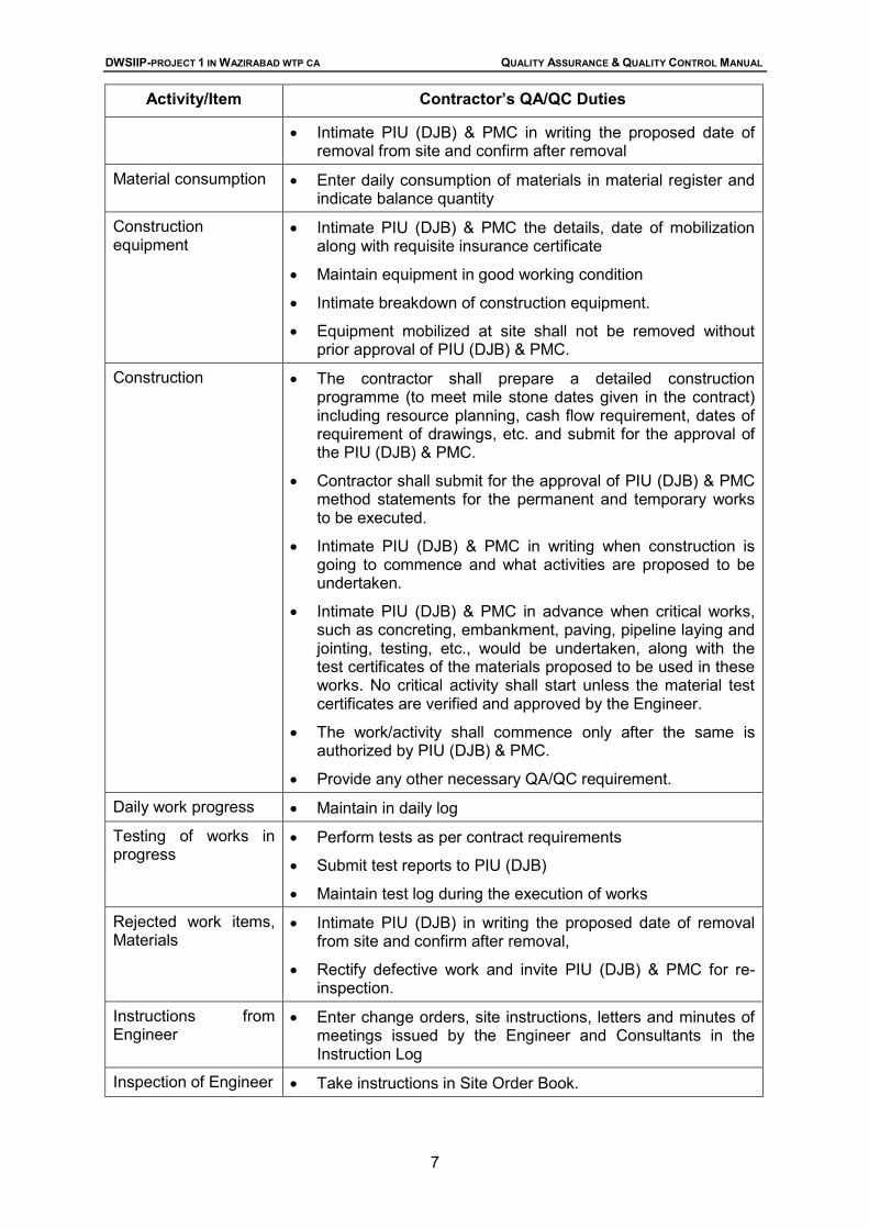
Table 1.1: List of Contractor’s QA/QC Duties Activity/Item Contractor’s QA/QC Duties
Designs for turnkey contracts
• Prepare designs using appropriate QA/QC procedures
• Submit designs, drawings, data sheets and implementation schedule to PIU (DJB) for review and approval
• Maintain design and drawing registers at site
• Use only latest revisions of approved drawings for construction, all other revisions to be marked superseded.
• Prepare and submit Process Design and Schedule.
• Submit Method statements.
Designs for item-rate contracts
• Maintain design register at site
• Use only latest revisions of approved drawings for construction, all other revisions to be marked superseded.
• Submit designs for enabling works
• Submit Method statements.
Test laboratory and equipment
• Submit to PIU (DJB) and PMC the details of equipment, programme of procurement and obtain approval. All equipment shall have a valid calibration certificate.
• Maintain the equipment in good condition and validate the calibration as appropriate.
Material receipts Materials testing
• Obtain approval of PIU (DJB) to the sources.
• Enter receipts in material register
• Materials to be tested only in approved laboratories
• Materials such as cement, reinforcement steel, structural steel, etc. shall have manufacturer’s test certificates.
• Material received at site shall have dispatch clearance, third party inspection reports.
• Materials shall be stored as per good engineering practice.
• Prepare concrete mix designs as required by contract and submit for the approval of PIU (DJB) & PMC
• Take test samples in presence of PIU (DJB) & PMC when requested
• Routine tests shall be carried out in site laboratory by qualified staff to be posted by the contractor.
• Submit test reports to PIU (DJB) & PMC with monthly reports maintain test log. Field testing registers shall be maintained
by the contractor.
Rejected materials • Enter in material register at site
• Tag and record all rejected materials
DWSIIP-PROJECT 1 IN WAZIRABAD WTP CA QUALITY ASSURANCE & QUALITY CONTROL MANUAL
7
Activity/Item Contractor’s QA/QC Duties
• Intimate PIU (DJB) & PMC in writing the proposed date of removal from site and confirm after removal
Material consumption • Enter daily consumption of materials in material register and indicate balance quantity
Construction equipment
• Intimate PIU (DJB) & PMC the details, date of mobilization along with requisite insurance certificate
• Maintain equipment in good working condition
• Intimate breakdown of construction equipment.
• Equipment mobilized at site shall not be removed without prior approval of PIU (DJB) & PMC.
Construction • The contractor shall prepare a detailed construction programme (to meet mile stone dates given in the contract) including resource planning, cash flow requirement, dates of requirement of drawings, etc. and submit for the approval of the PIU (DJB) & PMC.
• Contractor shall submit for the approval of PIU (DJB) & PMC method statements for the permanent and temporary works to be executed.
• Intimate PIU (DJB) & PMC in writing when construction is going to commence and what activities are proposed to be undertaken.
• Intimate PIU (DJB) & PMC in advance when critical works, such as concreting, embankment, paving, pipeline laying and jointing, testing, etc., would be undertaken, along with the test certificates of the materials proposed to be used in these works. No critical activity shall start unless the material test certificates are verified and approved by the Engineer.
• The work/activity shall commence only after the same is authorized by PIU (DJB) & PMC.
• Provide any other necessary QA/QC requirement.
Daily work progress • Maintain in daily log
Testing of works in progress
• Perform tests as per contract requirements
• Submit test reports to PIU (DJB)
• Maintain test log during the execution of works
Rejected work items, Materials
• Intimate PIU (DJB) in writing the proposed date of removal from site and confirm after removal,
• Rectify defective work and invite PIU (DJB) & PMC for re-inspection.
Instructions from Engineer
• Enter change orders, site instructions, letters and minutes of meetings issued by the Engineer and Consultants in the Instruction Log
Inspection of Engineer • Take instructions in Site Order Book.
DWSIIP-PROJECT 1 IN WAZIRABAD WTP CA QUALITY ASSURANCE & QUALITY CONTROL MANUAL
8
Activity/Item Contractor’s QA/QC Duties
• Intimate PIU (DJB) & PMC of compliance
Progress scheduling and control
• Prepare and maintain project schedules and undertake work in accordance with approved schedules, revise the schedules as and when required to meet the work requirement.
Reporting • Prepare and submit Monthly Progress Reports and other reports as per contractual requirements
Records Maintain the following records on Site/Contractor’s Office/Laboratory: • Material Register • Rejected Material Register • Site Order Book • Hindrance/ Delay Register • Daily Log • Design Register • Test Log • Test Reports • Site Laboratory Record • Instruction Log (to be maintained by PMC and Contractor
both) • Permissions Issued by Departments • Correspondence Record • Equipment Register • Labor Register • Approved Construction Drawings, drawing register • Copies of Monthly Progress Reports • Any other records as specified in the Contract and/or as
instructed by the Engineer • Visitor’s Register and • Material test Register
DWSIIP-PROJECT 1 IN WAZIRABAD WTP CA QUALITY ASSURANCE & QUALITY CONTROL MANUAL
9
2 PRELIMINARY PREPARATIONS 2.1 Work Before Going on Site
The Supervising engineer should have spent some time before he goes to site examining the contract agreement and drawings, particular and standard specifications, related IS codes etc. and be familiar with all aspects of the health and safety manual. He should have also taken the opportunity to have discussions with the designers. He should get to know how the contract has been designed, so that he is able to make intelligent suggestions if the conditions revealed during the course of construction differ from those expected. He should make a file of all information, which is basic to the contract, such as soil test data on which the design has been based; levels; rainfall and run-off data; geographical information and any other relevant data. The compilation of this file will effectively act as a check on the situation to date so that the Supervising engineer can advise the Engineer of any matters still outstanding that have to be settled. The Supervising engineer will take a large part of the responsibility for seeing that all site and contract matters are conducted in due time and in the right order. Thus, the tentative programme of construction will be one of the documents most carefully studied by the Supervising engineer so that he is ready to understand and check what the contractor proposes as soon as the work starts.
2.2 The Site office
Upon arrival on the site, one of the first things the Supervising engineer will have to decide is where he will have his office placed and what size and layout it shall have. If there is any choice in the matter, the office should be placed so that from it the main traffic in and out of the site can be observed. It is a mistake to choose a situation which overlooks the requirement but which does not have a view of the main entrance. Little worthwhile can be seen of the normal civil engineering job from a distance, whereas even a distant view of the entrance to it will enable the Supervising engineer to notice a number of happenings- the delivery of materials, plant going off the site, when callers are about to descend, and so forth. Adequate secure storage space is essential for storage of instruments and for storing special equipment to be incorporated in the job.
2.3 Initial Coordination with the Contractor
The question of an office and its sitting having been settled with the contractor’s representative, the next items to be discussed will almost certainly concern the laying on of services to the job – telephone, water supply, electric power, and drainage. Water supply will also be required; the contractor’s representative will seek the Supervising engineer’s consent for the source of supply used. The Supervising engineer should go out of his way to help in these matters, not only because upon them depends the effective start of the work but also because everything he can do to help the contractor’s representative at this stage will assist in building up a good relationship later. The question of drainage and sanitation may prove difficult to solve. The Supervising engineer has to watch that what was promised to be a small ‘sewage treatment works’ does not get whittled down to no more than a tank and a soak well, or a tank and overflow to a near-by ditch or river. This is the time to make sure that any sewage works proposed are of the right sort and are large enough to treat all the sewage from the maximum number of men who will be employed on the site. If these sewage works are later found inadequate, it may
DWSIIP-PROJECT 1 IN WAZIRABAD WTP CA QUALITY ASSURANCE & QUALITY CONTROL MANUAL
10
prove easy to get promises for their enlargement from the contractor, but considerably more difficult to get effective action if the contractor’s representative feels that , given a few more weeks, the numbers of men on the job will decline and the problem will solve itself. The question of waste oil disposal from plant is very important, and should be brought to the notice of the contractor’s representative. Discharge of used lubricating oil or waste diesel oil is to be controlled; to discharge it through the site sewage works may ruin their proper functioning; and the discharge of even small quantities to a river will not be acceptable. The waste oil should be led to a pit and disposed of by tanker.
2.4 Preliminary Issues and Contractor’s Programme
The Supervising engineer will next need to know what part of the job the contractor’s representative intends to tackle first, and from this may follow an immediate visit to that part of the site and a discussion as to the extent of the work required there and the necessary setting out that must precede it. The contractor’s representative will need to know what are the local benchmarks, which have been used for the original survey of the area and, if these are some distance away, they may both agree that their staff should jointly arrange for a convenient benchmark and base line to be set out on the job. When the immediate proposals for working have been sanctioned by the Supervising engineer the next topic is the programme as a whole, and this is the first of many such discussions that will occur. Sometimes the contractor’s representative wants more information from the Supervising engineer so that he can continue with making his detailed plans, or he may have perceived some problems ahead which he thinks might be avoided if the engineer would sanction some action not exactly in line with the correct requirements.
2.5 Early tasks for the Supervising Engineer
2.5.1 Recording of Existing Conditions
It is likely that excavation for foundation will have commenced, or will commence immediately, on a large scale. It will thus be imperative for the Contractor to take levels of the natural ground over the site where the excavation is to take place, if these levels are not already available in sufficient details. This is urgent work, for there will be no chance later of finding what the natural ground levels were, and the calculations for quantities of excavation will be largely intelligent guesswork, or agreement will have to be sought on bill of quantities/figures which may well differ from the true value. The contractor has to jointly record the existing ground levels at site with the Supervising engineer and get them certified. No claim of the contractor on account of variations in the quantities of excavation will be admissible in absence of the certified records. It is not sufficiently reliable to assume the ground levels, shown on the contract drawings are accurate, because they may have been based on previous mapping data that alterations may subsequently have taken place, or they may not be accurate enough for measuring quantities.
2.5.2 Disposal of Site Debris and Excavated materials
The question of the disposal of site debris and excavated material will have to be considered. The Supervising engineer must see that the top-soil is being stripped off and stacked separately for re-use if necessary. The removal and disposal of existing materials on the site or the pulling down of existing structures will have to be discussed.
DWSIIP-PROJECT 1 IN WAZIRABAD WTP CA QUALITY ASSURANCE & QUALITY CONTROL MANUAL
11
2.5.3 Scheduled Ordering of Materials by the Contractor
The next task the Supervising engineer may well be called upon to do, if he has not done it already, will be to check the ordering of materials necessary for the first stage of the work. The type of materials to be considered will be such things as the reinforcing bars required for concrete foundations and any pipes, which may be necessary to have during the early stages of construction.
2.5.4 Setting up of Site Administration Systems
It will be necessary to set up a clerical system for the handling of correspondence, filing, measurement of quantities and checking of contractor’s claims, and for log sheets of all technical data. Files, a filing cabinet, box files, diaries for everyone and a large site diary, level books, notebooks, graph paper, drawing paper etc. will be required.
2.5.5 Protection of the Environment
The contractor shall take all reasonable steps to protect the environment (both on and off the Site) and to limit damage and nuisance to people and property resulting from pollution, noise and other results of his operations. The contractor shall ensure that emissions, surface discharges and effluent from the contractor’s activities shall not exceed the values indicated in the Employer’s requirements, and shall not exceed the values prescribed by applicable laws.
DWSIIP-PROJECT 1 IN WAZIRABAD WTP CA QUALITY ASSURANCE & QUALITY CONTROL MANUAL
12
3 DOCUMENTS, RECORDS & REPORTING Document control is intended to provide a consistent framework for transmittal, receipt, recording, processing, filing and retrieval of documents, and to ensure commonality in formats. The most important documents for QA/QC are final design documents, test reports and instructions. A flow chart for control of these documents is shown in Figure 3.1. Document control procedures, including guidelines for correspondence control, are outlined below.
Figure 3.1: Flow Chart for Document Control
DWSIIP-PROJECT 1 IN WAZIRABAD WTP CA QUALITY ASSURANCE & QUALITY CONTROL MANUAL
13
An important part of the Supervising engineer’s work and QA/QC procedures is to keep adequate records. These records enable an appraisal to be made at any time of the progress of the work; they form the basis of fixing an accurate assessment in monitoring the contractor’s work, they enable all materials to be ordered in good time, they enable the designers to be assured that the assumptions made for design purposes are valid, they assist in the solving of new design problems that may arise during construction; and they form a source of information throwing light on the subsequent behavior of the completed works. Records may be categorized into the following four classes: • Historical; • Quantitative and Financial; • Qualitative; • “As Built” Records.
3.1 Design Document Control
As discussed earlier (See Section 2), final design documents (drawings, calculations, estimates, etc.) are generated at three separate levels, depending on the contracting procedure and type of work. These factors have been considered in suggesting the design document control system. 3.1.1 Turnkey Contracts The flow of final design documents prepared by the contractor in turnkey contracts shall be as follows: 1. The contractor shall submit four copies of design documents to PIU (DJB) for review,
using the Request for Design Approval (RDA) Format F-1 of Appendix C. 2. The PIU (DJB) shall send three copies of the documents to PMC for review and
comments, using the Request for Internal Design check Review and recommendation (RIDCRR) Format F-2 of Appendix C.
3. After review, the PMC shall return two copy of the documents with its comments, using the Internal Design check Review and recommendation Note (RIDCRR) Format F-3 of Appendix C.
4. Taking into account the comments of PMC, the PIU (DJB) shall accordingly return one copy of the approved design documents to the contractor, using the Design Transmittal Note (DTN) Format F-4 of Appendix C. Design documents shall be marked (or stamped) ‘Approved’, ‘Approved as Noted’ or ‘Not Approved’.
5. For design documents marked ‘Not Approved’, steps 1 to 4 above shall be repeated. For documents noted ‘Approved’ or ‘Approved as Noted’, the contractor shall submit originals to PIU (DJB) for affixing ‘Approved’ signatures (using a format similar to F-1.).
6. The PIU (DJB) shall have the design documents signed ‘Approved’ and return them to the contractor (using a format similar to F-4).
7. The design document details are to be recorded in the contractor’s Design/Drawing Register, using the Format F-5 of Appendix C. (Similar registers shall also be kept by PIU (DJB) & Item Rate Contracts (Wending Drawings).
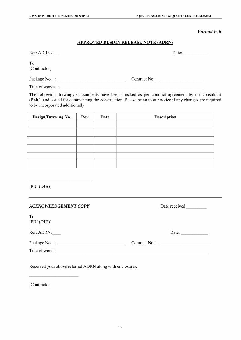
• The approved drawings shall be transmitted to the contractor by PIU (DJB), using the Approved Design Release Note (ADRN) Format F-6 of Appendix C.
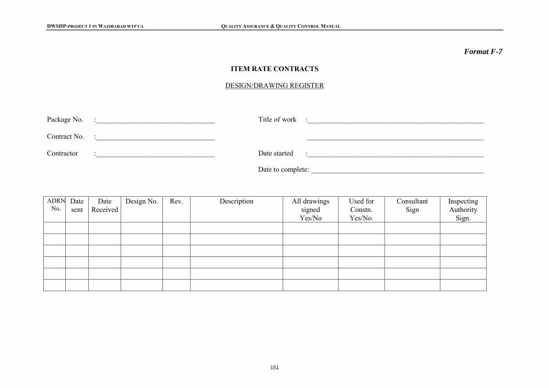
• The document details are to be recorded in the contractor’s Design/Drawing Register, using Format F-7 of Appendix C. (Similar registers shall also be kept by PMC.)
3.2 Test Report Controls
All the tests and field checks are to be carried out as per the applicable quality control requirements. The tests are carried out by the contractor who will designate (Engineer) a laboratory-in-charge authorized to carry out and sign test reports for him. The witnessing
DWSIIP-PROJECT 1 IN WAZIRABAD WTP CA QUALITY ASSURANCE & QUALITY CONTROL MANUAL
14
officer will sign the reports and put his name and designation. The flow of test report documentation shall generally be as follows:
• Two copies of all Test reports shall be submitted by the contractor to the PMC.
• The PMC with its comments shall forward one copy of the test reports to PIU (DJB).
• The PMC shall issue a Conformance/Non-Conformance Report (CNC Report) to the contractor after review of test results by the PMC, using Format F-10 of Appendix C. The CNC reports will have a running serial number for each contract package.
• The CNC report shall be entered in the Test Report Log by the contractor at the site, using Format F-11 of Appendix C. The details of input materials will be recorded in the Material Register, using Format F-12 of Appendix C. The contractor shall maintain all test records properly.
Other approvals given to the contractor will be recorded in the daily logs of the contractor which should form part of the contractor’s monthly report. A recommended format for Daily Work Record/Site Order Book is illustrated in Format F-13 of Appendix C. Similar procedures shall be followed for the transmittal and review of test reports for tests performed at outside laboratories, for manufacturers’ certificates, and for third party inspection reports.
3.3 Tracking of Instructions
During the process of construction, different agencies are expected to conduct site visits and instruct the contractor to ensure quality and timely construction within the costs to the extent possible. The multiplicity of agencies is a special feature of the Project. Hence there may be some ambiguity in the instruction flow if these are not transmitted and recorded properly. All the instructions to the contractor shall flow through the Engineer of the PIU (DJB). The instructions are of the following types:
• All instructions related to the contract administration including approval of the contract variation orders, time extensions, notices related to rate of progress etc. to be issued by PIU (DJB).
• The instructions regarding quality, testing, monitoring and work scheduling can be issued by the PMC also. In case of conflict of instructions of the PIU (DJB) & PMC in these matters, the instructions of the PIU (DJB) would prevail.
• Instructions issued during site visits or inspections of the PIU (DJB) & PMC, which are normally recorded in the contractor’s Site Order Book, shown in Format F-13 of Appendix C; and
• Instructions issued during review meetings in the form of minutes, letters, etc. All instructions noted above are to be recorded in the Instruction Register to be kept and maintained by the contractor using Format F-15 of Appendix C. Instructions also include notices of rejection of work inspected because it was found to be non-conforming to requirements and which has to be redone or rectified.
3.4 Contractor’s Site Order Book
The Contractor shall be responsible to maintain a Site Order Book, at the site of the works at all times, and this shall be open for inspection by authorized representatives of PIU (DJB) & PMC. The Site Order Book has two primary purposes – to record the day-to-day instructions to the Contractor and the Contractor’s compliance with these instructions, and to record the
DWSIIP-PROJECT 1 IN WAZIRABAD WTP CA QUALITY ASSURANCE & QUALITY CONTROL MANUAL
15
inspection and acceptance of work completion stages along with issuing approvals to the Contractor to proceed with the next stage of construction. As noted above, the status of the Contractor’s compliance with instructions issued is to be summarized in the Instruction Log (Format F-15 of Appendix C), and reviewed monthly by the PMC/PIU (DJB) and during the periodic Squad Checks. In cases where the Contractor has failed to comply with the instructions, the reasons therefore shall be determined and necessary remedial actions taken. The PMC and PIU (DJB) will maintain a file of site orders issued to contractor for record and compliance.
3.5 Correspondence Control
3.5.1 Site Filing System
One of the first matters to be dealt with is the setting up of a correspondence and filing system. An indicative list of the files likely to be required is given in Appendix-E. Out-going letters (including transmittal letters and notes) originating from various organizations involved in the Project: PIU (DJB), PMC, contractors, manufacturers, etc. shall be signed only by the designated project executive of that organization; for example: Project Director and Principal Chief Engineer, or person authorized on his behalf, PIU (DJB), PMC Resident Project Manager, Contractor or manufacturer authorized representative). All letters should have a reference code and number, and should refer to a single subject only, which shall be clearly stated on top of the letter, after the recipient’s address. All outgoing letters should be numbered sequentially. All replies should refer to the originator’s reference code and number and subject. Incoming correspondence should be stamped and dated, and preferably given an internal reference code and number. All incoming and outgoing correspondence should be logged chronologically, either in computer correspondence registers or in manual correspondence logs. Copies of outgoing correspondence and originals of incoming should be filed in chronological files at the document center of each project organization. There should be only one chronological file for all outgoing correspondence. Regarding incoming correspondence, there could be more than one chronological file, based on the volume of correspondence expected to be received from project related organizations (for example PIU (DJB) & PMC can maintain separate incoming chronological files for each contractor, etc.)
3.5.2 Drawing Register
A register for drawings should be maintained by the contractor. The most efficient method is to set up two registers of drawings; the first recording all drawings received; the second recording all drawings made on site. The incoming drawings will need no number added to them, since they should all possess an original number. All that is necessary is to ‘book’ them in and mark the revision and date received. The register for drawings made on site should show the following details:
• Consecutive number of drawing;
• Subject and revision of drawing;
• Size and type of drawing;
• To whom copies are sent and when.
DWSIIP-PROJECT 1 IN WAZIRABAD WTP CA QUALITY ASSURANCE & QUALITY CONTROL MANUAL
16
A register is not consulted by a person who knows where a drawing is; it is only consulted by those who do not know. Hence a description of what one is looking for is helpful.
3.6 Historical Records
Historical records show progress stage by stage, as proposed and as achieved, including all relevant information having a bearing on this subject, such as records of weather, notes of discussions, decisions, and other key matters influencing the course of the job. The principal records that have to be kept in this category are:
• inspection daily returns;
• the site diary and related records;
• the Supervising engineer’s diary;
• the weekly and monthly reports;
• instructions to contractor; and
• sketches to contractor.
3.6.1 Inspection Daily Returns
The Inspection Daily Returns form is an excellent record of the daily work on site, to be prepared by the contractor and checked by the inspector. An example is shown in Figure 3.2. The sheet shown is purposely simple; it concentrates on extracting, through the inspector, information as to the work completed during the day; how many men were engaged on each part of the project; details of delays; and other related and pertinent issues. The supervising engineer, or inspector, is not asked to answer a complicated questionnaire; he references at the top of the form to remind him of the separate parts’ of the works, and he is asked to report all delays. The form not only focuses the supervisors activities for the day (he must visit all parts of the works and report thereon) but it also gives the supervisors a chance to communicate with the office. The daily returns form an invaluable record, being of great help should any later dispute arise with the contractor as to progress or payment for standing time or extra work
3.6.2 Site Diary
The Site Diary is a day-to-a-page diary which is built up from the Inspector’s time sheets, all relevant notes about visitors to site, engineers’ operations, and any other related matters. Weather records should be kept in the diary recording maximum and minimum temperatures and what time is lost due to rain. It might be thought that temperature records are not really necessary, but sometimes inexplicable events or failures occurring later, in parts of the structure, may be traced to the weather prevailing at the time. One wall of a tank may, many months after construction, be found under test to spring an unaccountable number of leaks or damp patches in comparison with other walls, and a reference to the weather diary, which reads, ‘Heavy showers throughout the day’, may remind someone that a downpour of rain sent the men scattering for cover and that, in the general haste to get the wall concreted before further deluges, punning or vibrating of concrete was probably sketchily done.
DWSIIP-PROJECT 1 IN WAZIRABAD WTP CA QUALITY ASSURANCE & QUALITY CONTROL MANUAL
17
Similarly, efflorescent patches on brickwork may be traced to building in wet weather, and cracks in concrete found to be probably due to high temperatures and sunshine prevailing for a period after concreting.
3.6.3 Supervising Engineer’s Diary
The Supervising Engineer’s Diary will be different from the site diary, as it will aim to record all major decisions made and instructions given. It is not an easy document to keep. On busy days it is often difficult to find the time to write down the day’s activities; on ‘off-days’ there is apparently so little happening that nothing worth recording can be recalled. However, effort should be made to keep to a system, and it is as well to make a list beforehand in the front of the diary of special points to be noted. Of course, the Supervising engineer’s own diary will be a personal record of events, and therefore in some cases confidential. His main endeavor will be to note down points about which there may later be some argument. Examples are: • the visits of all representatives to the site;
• any disputes which have arisen during the day, and particularly any verbal instructions he gave as a result;
• any particular points regarding the work which he does not necessarily wish to raise with the contractor at present; and
• any notes regarding particular stages of work or operations carried out.
DWSIIP-PROJECT 1 IN WAZIRABAD WTP CA QUALITY ASSURANCE & QUALITY CONTROL MANUAL
18
Figure 3.2: Inspection Daily Report Date ...............................
Shift: Night/ Day Work Done by Contractor No. of Men (1) Excavation, (2) Pipeline Installation, (3) Concreting, (4) Shuttering, (5) Pump House, (6) Foundations to Intake Well, (7) Miscellaneous. (1) Excavation: (flank of northern radius) Visited site but no work completed by the Contractor as agreed under Site Instruction No. xyz. Testing schedule to be agreed.
(1) Excavation 1 dozer in poor condition to be removed from site and replaced immediately Chainage 1+254 U/S trench siding collapse rectified and trenching shoring in place on each side. Bank shoring in place as agreed. Placement of backfill material delayed due to requirement for improved material: imported material for the critical section due too be delivered from zone A shortly. Contrcator informed under Site Instruction abc. Pipe bedding preparation for section of trench chainage 1+380 to 1+ 475.
Labourers directing traffic excavating for settlement apparatus north of wall and cleaning out term drainage channel south of wall. 2nd D8 also assisted new 38 RB down quarry road.
(4) Shuttering: (anchor blocks to 1500mm main) Crane in place until 2.30 pm. Carpenters and masons awaiting the delivering of supporting bolts and timbers. Drillers delayed 3 hrs. Rock encountered at Chainage 2+500 US: extent of work to trench formation ( noted as 350mm for full width of trench) in fabricating special shuttering for anchor blocks. Drilling rock faces, Shotfirer and 1 labourer Request for blasting denied. New dozer removed to excavation works.
1 Head Carpenter 1 Head foreman 1 Drilling machine 2 Lorry driver 4 Labourers
(5) Pump House 13 labourers working at the dry well in preparation of bases for casting due in two days. Middle access road to site in needs of temporary works, SI to be issued to Contractor as discussed in Progress Meeting and recorded minutes.
Sump location formation levels agreed and finalized at 12.30 pm. 13 labouere working at green road tidying up verges, helping masons to make channels for dewatering.
(6) Foundations to Intake Well 15 labourers working at the excavated formation in preparation of bases for casting due in two days.
(7) Miscellaneous Men grubbing, felling and removing trees: 10 finished at 12.30 pm.
1 Foreman
16 labourer REPORT ALL DELAYS AND BAD WORK 1Dozer broken down all day 1 compressor taken from site for repairs: broken down all day 1 truck broken down from 9 am.
Time lost and no. of men Involved 1 Dozer & driver 1 plate compactor malfunction: 2 lab
Hours worked by Supervisors...9 ½ ....
Signature: Contractor’s Site In Charge .................................
DWSIIP-PROJECT 1 IN WAZIRABAD WTP CA QUALITY ASSURANCE & QUALITY CONTROL MANUAL
19
3.6.4 Weekly Monthly Reporting
The contractor will submit a Weekly Report in duplicate copy. This will be checked by the supervisor and a copy of the report sent regularly from the Supervisor to the Engineer, describing in summary the job events of the week. A typical example is shown in Figure 3.3. The monthly report is a more generalized summary of progress, written in a fashion which is suitable for presentation to the PIU (DJB). It will not be so technical as the weekly report for submission to the Engineer, but it will still be clear and concise. The Supervising engineer will submit the monthly report direct to the Engineer, and copies to agreed recipients.
3.6.5 Day to Day Instructions to Contractor
There are often daily occasions when it is necessary to inform, or make requests to, the contractor about the work. Some simple system of sending notes to the contractor’s representative or to member of his staff is necessary. It is best to have only one book in use at a time, all staff writing their notes in it, the carbon copy which remains in the book representing a daily log of all detailed written instructions sent to the contractor’s representative. Many small but important matters can be dealt with in such a manner—notes about levels set out, notes about shuttering, type of materials to be ordered, results of concrete tests, minor complaints and reminders, details of dimensions and setting out, elucidation sketches, and so on. The notes are handwritten, the sketches freehand, the signature being that of the person providing the information. The carbon copy remaining, forms a useful record in many ways. It forms a kind of ‘central notebook’ in which basic levels appear; the sketches and dimensions are useful for making alterations to the record drawings and for computing quantities of work done. In addition, it forms an excellent ‘source of information’, enabling the Supervising engineer to see in a moment or two what instructions his staff are currently giving the contractors staff. For more lengthy notes to the contractor, or where more than two copies must be sent out (e.g. two for the contractor’s representative and a third copy for related stakeholder), typed notes may be necessary, and these should be headed ‘Memo to contractor’s representative’ rather than be put on official notepaper
3.7 Quantitative and Financial Records
Quantitative and financial records measure all that is done, the time and rate it is done, together with all relevant particulars, so as to form a basis of fair payment to contractors and for the furnishing of figures which show the cumulative cost of the job, the cost of separate parts of it, and the estimated total final cost at any time.
3.7.1 Quantity Records
The contractor shall submit the measurements for verification of the Supervising Engineer. Certification of the measurements/quantities will be one of the more important tasks of the Supervising engineer and his staff. Many techniques of measurement may be employed, but the main essential for them all is to comply with owing two simple rules: • it should be possible to ascertain immediately from the records what has been measured
and what has not; and • the records must clearly show what has been paid for, as distinct from what has been
measured. If this is not clear from the start, then endless confusion will result.
DWSIIP-PROJECT 1 IN WAZIRABAD WTP CA QUALITY ASSURANCE & QUALITY CONTROL MANUAL
20
Figure 3.3: SAMPLE Weekly Report Weekly Report No. xx
(For week ending xx th June 20xx) CONTRACT PACKAGE REFERENCE NUMBER CONTRACT TITLE: Bill item 52. Extension to Pump house Continuous rain delayed waterproofing of roof until 5 plastering sub-contractors started work on 21st. They will finish next week. Installation of switchboard awaits arrival of manufacturer’s fitters promised for 29th. Labour: 2 plus 2 plasterers. Bill item 54: Electrical re-wiring Cable laying completed but awaits connection to switchboard. Lighting wiring completed as far as possible. Contractor withdrew men from site on 24th and will return to complete after switchboard connection made. Bill item 57: Main laying The extra sluice valve required at Ch. 3500 was delivered. This completes all deliveries under the valve contract (Contract 53). Materials to Site: Delivery of steel 6oo mm dia. pipes continues. Total delivery to date 4600 m or 82 per cent order (Bill item 55). Supply of small cast-iron pipes and fittings continued. Only a few items now outstanding (bill item 56). Approx. 260 m of pipe laid during week by two gangs working from point ‘F’ forward and point ‘G’ back; chainages 3260—3840 and 4480—4210 respectively. Suppliers are being pressed for delivery of special T-junction Ch. 3500 which is promised for next week. The crossing under the two main-line tracks was completed successfully at Ch. 4400 and in 14 hrs. continuous working. Labour: I General Foreman, 2 section foremen, 3 gangers, 3 jointers, 7 drivers, II labourers. Plant: 2 back shovels; crane; 3 dumpers; dozers; 2 concrete mixers; 4 lorries (5 ton). Testing. Testing to point F from H was satisfactory and the section left out at Point F for testing was re-inserted and the line made good. Main has now been passed from Ch. 500 to Ch. 3260. Miscellaneous, A director of Messrs. Smith accompanied by the sports ground manager inspected the reinstated trench through the sports ground and was satisfied. General Notes: Weather: Wet. 2.55 cms rain
Temp. 57° to 68° F. Lost time: 2.men x 6 hrs. Contract 52.
Nil Contract 57. Visitors: Director Messrs. Laxmi & Co. 25th
District road inspector to Contract 57. 25th Representative pipe suppliers. 21st.
Signature / date ………………
Contractor’s Supervising Engineer
DWSIIP-PROJECT 1 IN WAZIRABAD WTP CA QUALITY ASSURANCE & QUALITY CONTROL MANUAL
21
The records should therefore be divided on lines which are suggested as follows:
• A series of notebooks containing sketches and dimensions of work as executed, where different from the contract drawings;
• A book or file containing the working out of the quantities;
• A summary of the quantities from time to time worked out, classified under bill items; and
• A final summary of quantities agreed for payment on each certificate.
3.7.2 Field Note Books
The first records for quantities mentioned above will be in field note books, and the data will be placed therein from time to time as the work proceeds. This data shall be collected by the contractor’s quantity surveyor or measurement engineer and written in collaboration with the Supervising engineer acting in so that the measurements are agreed on site. Accuracy, clarity, and sufficiency of measurements are essential. As the monthly date for measurement of quantities approaches, the supervisors and related staff will bring the certified measurement notebooks up to date and ready for use in the calculation of quantities. The items of the bill will be through in order and the necessary calculations under taken to find out the amount of work done during the month under each item. At this point there are two alternative systems which can be used. In the first system a loose-leaf file is set up, consisting initially of a page each item, further pages being added as necessary later. Refer to Figure 3.4, which illustrates the necessary quantity calculations are inserted for each item. (A page from the quantities register: Loose Leaf) Figure 3.4: Quantities Register
Add central circular pits 2/π, 15², 1.25 = 1782 cu. m.
2 No. Rad of 15m
Cert. 2 (400 paid)
cu.m. 387
1782
2169 CERTIFICATE 3. Main tank depths after stripping 1.64 24.5m 1.44
8m Av.d = 1.58 1.49 Av. Av.d = 1.40 1.52 1.36 V = 24.5 x 1.49 x 8.0 292 Add inlet trench: 1.0 x 2.0 x (2.1+1.2) = 6.6 Add outlet sump: 3.1 x 1.7 x 0.5 = 2.6 drain: 1.5 x 1.9 x 0.55 = 1.5 302.7
303
Cert. 3 (828 paid)
2472
Note: This is the working-out register of the quantities, and preferably Consists of a file loose -leaf sheets so that further sheets may be inserted as necessary for any particular item.
DWSIIP-PROJECT 1 IN WAZIRABAD WTP CA QUALITY ASSURANCE & QUALITY CONTROL MANUAL
22
In the second system, bound calculation books are used, the quantities for the month being calculated item by item and then the month ‘ruled off’. Because extra leaves cannot be inserted when bound books are used under this system, a page reference system must be used so that the quantity measured up to the last certificate for any item brought forward as the starting quantity for the current month’s addition measurement. This is necessary because the amount entered in the bill of quantities is always the cumulative total measurement since the contract started, not just the total completed for the month. The difference between these two systems is one of convenience The first system is physically not quite so convenient as the second, since calculations have to be inserted in a bulky loose-leaf file (or in separate files) rather than in easily handled calculation books. On the other hand, under the system all the quantity calculations for any one item are collected together; whereas under the second, the quantities for any particular item must be referenced through the calculation books, and an error of referencing may result in quantities being missed out or being measured twice. In the hands of competent staff; however, either system works well.
3.7.3 Comparison of Measured Quantities and Contractor’s Claim
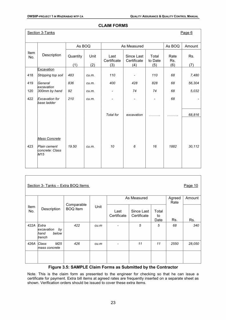
With regard to comparison of measured quantities with the contractor’s interim claims, calculated quantities must now be compared item by item with the quantities claimed by the contractor in his monthly claim. The monthly claim form from the contractor should be presented according to the sample form shown in Figure 3.5. The comparison required is between the contractor’s quantities under the heading ‘total to date’, column (s), and the Supervising engineer’s own certified quantities. Where differences are found conversations with the contractor’s site staff will be necessary. It may be that quantities put forward by the contractor are less than quantities certified by the engineer, or, as previously mentioned, they may be arbitrary figures used for payment purposes only. Thus, for bulk excavation which has only been partly completed, it is a waste of time trying to compute accurately the quantity excavated to any given day. The quantity, as finally excavated to the underside of the foundations, and so on, is the figure that must be exact, and this calculation need only be undertaken when foundation excavations are completed.
3.7.4 Authorization and Measurement of Extra Works
Any extra or varied works must be authorized in writing by the engineer. Verbal orders may be given, provided this is later confirmed in writing either by the engineer sending some authorization to the contractor or the contractor confirming the orders by a letter to the Engineer. It is frequently impossible for the engineer to send a written variation order to the contractor in advance of the variation being undertaken. What happens is that agreement is reached between contractor’s representative and Supervising engineer on the site that a certain matter ‘shall be covered by a variation order’, and it is then up to the Supervising engineer to submit a draft order to the engineer for his signature. A typical variation order issued is shown in Figure 3.6.
DWSIIP-PROJECT 1 IN WAZIRABAD WTP CA QUALITY ASSURANCE & QUALITY CONTROL MANUAL
23
CLAIM FORMS Section 3-Tanks Page 6
Item No. Description
As BOQ As Measured As BOQ Amount
Quantity
(1)
Unit
(2)
Last
Certificate (3)
Since Last Certificate
(4)
Total
to Date (5)
Rate Rs. (6)
Rs.
(7)
Excavation
418 Stripping top soil
483 cu.m. 110 - 110 68 7,480
419 General excavation
836 cu.m. 400 428 828 68 56,304
120 300mm by hand
92 cu.m. - 74 74 68 5,032
422 Excavation for base ladder
210 cu.m. - - - 68 -
Total for excavation ………. ……….
68,816
Mass Concrete
423 Plain cement concrete: Class M15
19.50 cu.m. 10 6 16 1882 30,112
Section 3- Tanks – Extra BOQ Items Page 10
Item No. Description
Comparable BOQ Item
Unit
As Measured
Agreed Rate
Rs.
Amount
Last
Certificate
Since Last Certificate
Total
to Date
Rs. 422A Extra
excavation by hand below trench
422 cu.m - 5 5 68 340
426A Class M25 mass concrete
426 cu.m - 11 11 2550 28,050
Figure 3.5: SAMPLE Claim Forms as Submitted by the Contractor Note. This is the claim form as presented to the engineer for checking so that he can issue a certificate for payment. Extra bill items at agreed rates are frequently inserted on a separate sheet as shown. Verification orders should be issued to cover these extra items.
DWSIIP-PROJECT 1 IN WAZIRABAD WTP CA QUALITY ASSURANCE & QUALITY CONTROL MANUAL
24
VARIATION ORDER No……………..
Job…………………………………………………………………………………………………... Contract No……………………… Description………………………………………………... Contractor…………………………………………………………………………………………… In accordance with and subject to the Conditions of Contract you are hereby instructed to execute the following work: The prices to be allowed for the above work shall be: This work is additional to/ substituted/ or work hitherto included in the Contract. You are instructed to omit items of work as follows: ESTIMATED NET EFFECT ON THE COST OF WORKS This Variation Order ………………increase/decrease Add total effect of previous Variation Orders issued ………………increase/decrease
Total estimated effect ………………increase/decrease
Signed………………………………. Signed …………..…………………………. Supervising Engineer Engineer Date ………………………………… Date ……..……………..
Figure 3.6: Typical Variation Order
DWSIIP-PROJECT 1 IN WAZIRABAD WTP CA QUALITY ASSURANCE & QUALITY CONTROL MANUAL
25
3.7.5 Extra Incidental Works
Normally the Supervising engineer and contractor’s representative would come to an agreement as to the price to be paid for the extra incidental or varied works, before the draft order is submitted to the engineer for signature. This price is an agreed rate for payment by measurement based on standard rate analysis with current costs and input for material and labour.
3.7.6 Other Records
Where long pipelines are laid it is usual to produce a pipe-laying record book which itemizes in sequence the laying of every pipe and fitting which has been laid. The invert levels of pipes are given in metres O.D. either to every pipe or at very point of change of gradient. Notes as to bedding, haunching, or surrounding in concrete are given, and each fitting or cut pipe is described. From time to time offset distances from near-by buildings or other landmarks to particular fittings, such as bends where a change of direction occurs, are noted in the record book, so that their position can be found afterwards if required. The cumulative chainage from the starting-point is given as measured on the ground. Large s and drains crossed by the trench are similarly logged in a record book. Where plant or proprietary equipment has been included in the works, the contractor shall make up a data file which lists the maker of such plant and equipment, the original order reference and date, and any technical and other details of the plant. If the plant requires attention later on the employer will find it useful to have particulars concerning the original order. Instruction manuals and plant test data, such as performance curves of pumps, turbines, and motors, should all be submitted by the contractor to the employer in two sets of each, together with a set of the manufacturer’s drawings in each case. The impression might be gained that practically the whole of the Supervising engineer’s time is occupied with paper work, but this is really not so. The size of the Supervising staff will vary with the size of the contract and it will be found that the keeping of the essential records outlined herein will only take up intermittent time. Records that are so complex that nobody can find the time to keep them going, are of no value at all, and the Supervising engineer should therefore first concentrate on getting down on to paper notes about things which cannot afterwards be checked. Sketches and dimensions of work, which is later to be hidden and notes on the number of men and hours worked on extra works are therefore the first essential records.
3.8 Qualitative Records
Qualitative records include all measurements and observations of the quality and behaviour under test of the component parts of works, the raw and made-up materials used, and the foundation - and other conditions whose characteristics have an influence on the behaviour of the works.
3.8.1 Register of Test Results
The contractor shall maintain a separate register to record results of all field tests and for every kind of testing procedure adopted on site, refer to the relevant sections of the QA/QC Manual. Initially, Register/files might be opened for the following: • Borehole: Trial Pit: Auger hole Logs; • Grading analyses of Fill Materials, subdivided:
Specified requirements Actual results obtained.
DWSIIP-PROJECT 1 IN WAZIRABAD WTP CA QUALITY ASSURANCE & QUALITY CONTROL MANUAL
26
• Proctor density tests; • In-situ density tests; • Concrete aggregate tests; • Concrete cube tests; and • Miscellaneous tests. The above list presupposes that the work includes foundation testing, earth placing, concreting, which are all normal operations in connection with a civil engineering contract. Other files may be opened for other sorts of test results in connection with other types of civil engineering construction, according to the nature of the contract.
3.8.2 Sample Register
Whenever more than a few samples of natural materials are likely to be taken for examination (and since the Supervising engineer will never know at the beginning of any job how many samples will be taken, he had best assume it will be a large number) it is important to open a sample register, in which every sample is booked down, no matter for what purpose. The numbering of the samples can be straight forward, just as they come to hand, care being taken to label the sample itself with the same number. Once this is done, the sample can always be referred to later by its number in correspondence and reporting, and all the details of how it was obtained, etc., can be traced back to the sample register. If consecutive numbering is not adopted, confusion and mix-up will sooner or later break out from trying to describe samples by other systems, such as by using grid references on site; or TP/ 1/1, TP/ 1/2 meaning Trial Pit No. 1, Sample 1; Trial Pit No. 1, Sample 2; and so on. The register can consist of a ruled book which has columns ruled vertically, headed in sequence from the left to right across both pages as follows: Col. 1. Sample number 2. Source (e.g. borehole, trial pit, etc.) 3. Location (e.g. chainage, grid ref.) Col. 4. Depth
5. Description (brief only) 6. Container 7. Date taken 8. Where tested 9. Remarks/references
Each sample need take up no more than two or three lines down the page, and perhaps not all the columns need have an entry for each sample. It is important to keep the system simple and brief, so that no one has any trouble keeping it going.
3.8.3 ‘As-built’ Records and Drawings
‘As built’ records are very important and consist of pictorial records (the Record Drawings, etc.) of all the works as completed, showing the whereabouts at dimensions of all parts as they exist at completion, together with factual descriptions of their origin, their operation as described in instruction manuals, and their performance under test. Little need be said on the topic of record drawings. Every engineer has come across cases where record drawings of previously built structures have never been made, or have been inadequately made, and has known the great difficulties that arise as a result, often causing a costly amount of work to be undertaken to expose foundations or to locate buried pipes. The work on record drawings should continue throughout the contract, a special set of contract drawings being provided on which the contractor shall mark out all deviations from the original design. From time to time, where extensive alterations are encountered, or
DWSIIP-PROJECT 1 IN WAZIRABAD WTP CA QUALITY ASSURANCE & QUALITY CONTROL MANUAL
27
where preliminary surveys are made, completely new record drawings will have to be made. The Supervising engineer will check each drawing for correctness and certify. On numbers of occasions clarification of the existing contract drawings upon points of detail may be asked for by the contractor, such as a quick detail sketch of footing work for the bricklayer. If these freehand sketches are always drawn in a carbon-copy book the carbon copies will form an exceedingly valuable record in the Supervising engineer’s office for record- drawing alterations, extra works, and so on. Even for such items as working out of sight rail heights for laying drains, position of holes to be left in concrete, and so on—if these and all the other odd little sketches produced in the Supervising engineer’s office are automatically scribbled down on the carbon-copy book the record so obtained will be found to be extremely valuable. Where pipes are laid underground special care must be taken to chart the course of these pipes accurately, marking valve and stopcock positions and hydrants. The only way to get a really permanent record of the positions of such valves, etc., is to measure the distance from buildings and ‘tie-in’ by two or more measurements. Measuring from frontages, or from kerb lines or road centres, gives only transitory information, as these reference lines may later he altered in position.
3.9 Contractors’ Progress Reports
The contractor’s Monthly Progress Report, along with his monthly running bill, shall be submitted to the PMC (who will give a receipt) by the 8th of the month (original plus required copies as required). To facilitate timely payment, joint measurements shall be taken by the Contractor and the PMC by the 5th of each month, prior to close of the reporting period. The PMC Engineer will certify the agreed measurements. The process of taking measurement will be witnessed by the PIU (DJB) who will verify the measurements in the Measurement Book. The reporting period would be up to end of previous month.
DWSIIP-PROJECT 1 IN WAZIRABAD WTP CA QUALITY ASSURANCE & QUALITY CONTROL MANUAL
28
4 CONSTRUCTION QUALITY CONTROL – GENERAL This section provides an overview of construction quality control activities, including testing and site inspection. Materials control requirements are presented in detail in Section 4, while specific testing and inspection requirements for each category of works are presented in Sections 5 to 9 of this Manual.
4.1 Introduction
Construction quality control (CQC) is intended to provide a comprehensive, common and consistent framework for quality control across various contract packages. CQC comprises two main elements of quality control:
• Testing
• Inspections Testing control covers the type of tests to be carried out, frequency of testing and stage of testing. Inspection control covers the timing of inspections, what has to be inspected and the inspection procedures. CQC should be affected at five stages:
• Input Materials and Equipment Components
• In-process Activities
• Stage Completion
• Interfacing (of special importance in water supply and age contract packages)
• Final Completion The contractor is responsible for informing PIU (DJB) / PMC giving sufficient notice time so that they can witness the tests.
4.2 Testing
Various site tests on materials and works are required to be carried out by the contractor during construction. A well-equipped and properly operating site test laboratory is an important element of the quality assurance plan. A checklist showing typical testing equipment to be provided in the contractor’s site laboratory is presented as Table 4.1.
4.2.1 Field Testing Laboratory
The contractor shall be required to establish a complete field testing laboratory and arrange all the relevant codes and standards. The contractor shall set-up the site laboratory within 2 weeks after getting letter to proceed and inform the PIU (DJB) for conducting inspections. Laboratory equipment shall be properly calibrated, and calibration certificates and its updating as and when required should be kept at the laboratory for review by PIU (DJB) & PMC, as necessary. Specialized tests at outside laboratories, to be approved by PIU (DJB), shall only be undertaken with the prior approval of the PIU (DJB).
DWSIIP-PROJECT 1 IN WAZIRABAD WTP CA QUALITY ASSURANCE & QUALITY CONTROL MANUAL
29
Tests should be performed in accordance with the contract documents. The control of test reports shall be done as stipulated in Section 10 of this Manual. All test samples should be preserved, with proper identification numbers, test log reference, test date, and other applicable information. These samples must be stored at contractor’s office/laboratory by the contractor.
4.2.2 Outside / Independent Testing Facilities
Extensive testing of the material used for construction is a pre-requisite for attaining high quality of work. This shall also require specialize test, physical, chemical, ultrasonic, X-ray and various others type of tests which cannot possibly be carried out in a site laboratory. These laboratories may be in the Government sector, semi govt./private sector as approved by competent authority of DJB.
DWSIIP-PROJECT 1 IN WAZIRABAD WTP CA QUALITY ASSURANCE & QUALITY CONTROL MANUAL
30
Table 4.1 Checklist of Testing Laboratory Equipment
Contract Package No: ____ Name of Work: ________ Contractor Name: ___________
Testing Equipment
Type of Test Yes (1)
No (1)
1. Balance i. 7 KG to 10 KG capacity
semi-self indicating type-accuracy 10gm.
ii. 500gm. Capacity, semi-self indicating type-accuracy 1 gm.
iii. Pan balance-5 kg. capacity- accuracy 10 gms.
iv. Chemical balance-100 gm capacity-0.1 gm accuracy.
v. Platform scale-300 kg capacity.
2. Measuring apparatus and
hand tools:- i. Dial guage-25mm travel-
0.01mm per division(2 nos.).
ii. Graduated measuring cylinders 200 ml capacity-3 nos. and 1000 ml capacity 1nos.
iii. Distant reading thermometers.
iv. Steel tapes 3 mtr., v. vernier calipers , vi. micrometer screw 25 mm
gauge, vii. plumb bob, viii. spirit level, ix. wire gauge disc, x. foot rule, xi. long nylon thread, xii. magnifying glass, xiii. screw driver 30 cm long, xiv. ball pin hammer 100 gm
General laboratory test
DWSIIP-PROJECT 1 IN WAZIRABAD WTP CA QUALITY ASSURANCE & QUALITY CONTROL MANUAL
31
Testing Equipment
Type of Test Yes (1)
No (1)
Oven Electrically operated, thermostatically, controlled upto 110 0 C- sensitivity 10 C and upto 200 0 C for determination of loss on heating of bitumen.
Drying and moisture content determination
Sieves – As per IS 460-1962
(i) I.S. sieves - 450mm internal dia, of sizes 100 mm, 80 mm, 63mm, 50 mm, 40 mm, 25 mm, 20 mm, 12.5 mm, 10 mm, 6.3 mm, 4.75mm, complete with lid and pan.
(ii) I.S. sieves- 200mm
internal dia (brass frame) consisting of 2.36mm, 1.18mm, 600 microns, 425 microns, 300 microns, 212 microns, 150 microns, 90 microns, 75 microns, with lid and pan.
Sieve shaker and Hydrometer- capable of 200 mm and 300 mm dia sieves, manually operated with timing switch assembly.
Grain size analysis and classification of soil and aggregates
Atterberg limit apparatus Plasticity of Soil Procter/modified proctor (IS heavy) density equipment
Soil compaction test
Sand replacement cylinder and core cutter
In-situ density test for field compaction control
Compression testing machine 100 MT and 5 MT capacity Electrically cum Manually operated
Compressive strength of cement, concrete, brick, etc.
Cylinder and cube moulds for concrete and mortar
Concrete sampling
Slump cone apparatus Workability and control of water in concrete casting
Vicat apparatus Setting time determination of cement Laboratory CBR equipment Determination of strength of road
pavement and layers
Dynamic cone penetration test equipment
Determination of strength of road pavement and layers
SPT equipment and hand auger Boring, sampling and soil strength test
DWSIIP-PROJECT 1 IN WAZIRABAD WTP CA QUALITY ASSURANCE & QUALITY CONTROL MANUAL
32
Testing Equipment
Type of Test Yes (1)
No (1)
Unconfined compression testing machine
Determination of shear strength of cohesive soil
Direct shear equipment Determination of angle of internal friction of soil
Consolidation test equipment Determination of settlement /compressibility of soil
Los Angles Abrasion test/ Impact Testing Machine
Los Angeles Abrasion test/ Impact Test
Core drilling equipment In-situ sampling Bitumen test equipment Ductility test and
Penetration test
Pressure Gauges and Pumps Pressure Testing Marshal stability test equipment Road works. To be available at Hot Mix
Plant site.
Rapid Moisture Meter Checking moisture content at site Metallic Contact Digital Thermocouple
Checking temperature of bitumen
Sampling tins with rods 100mm dia × 50mm ht., 1/2kg capacity, and miscellaneous items like moisture tins etc., Moisture meter for timber Rebound hammer for testing concrete.
General laboratory test
Note: 1. Yes or No to be tick marked by PIU (DJB)/PMC to indicate the equipment at the site laboratory)
In addition to tests performed on site, the contractor is responsible for specialized tests which are performed at approved laboratories, and for third party inspections at manufacturing premises of various materials and equipment components, as stipulated in the contract documents.
4.3 Site Inspections
Site inspections shall be carried out to ensure that the materials and construction activities conform to the prescribed standards. Site inspections can be divided into day-to-day supervision and periodic quality inspection. The suggestions in respect of these two have been elaborated herein.
4.3.1 Day-to-day supervision
The day-to-day site supervision of all construction activities shall be carried out by the PMC. This includes checking of lines, levels and layouts and on-site checks. Progress monitoring and expediting shall also be carried out by the PMC. The Supervising team of the PMC shall ensure that materials that have been rejected or for which a conformance report has not yet been issued are not used in works. Construction equipment is a major component of quality assurance system. The equipment requirements have to be submitted by the contractor. The PMC will check the adequacy of the equipment used by the contractor for construction as per the prescribed standards and
DWSIIP-PROJECT 1 IN WAZIRABAD WTP CA QUALITY ASSURANCE & QUALITY CONTROL MANUAL
33
specifications. The contractor shall maintain daily logs and Equipment Register for the equipment used for construction.
4.3.2 Periodic quality inspections
Senior Engineer of PMC & PIU (DJB) shall carry out periodic quality inspections during in-process, stage completion, interfacing and final completion, and during all critical activities as per the following examples:
• excavation
• formation of embankments
• placing of reinforcing steel
• concrete batching and pouring: 100% in presence of Support Engineer PMC and JE :PIU (DJB)
• hot mix operation
• laying of pavement layers
• laying and jointing of pipes
• installation of electrical and mechanical equipment
• testing, trial runs and commissioning of electro-mechanical equipment and plants
• Completion of excavation Trenches for Pipe laying
• Completion of Laying and jointing of pipes
• Pressure/leakage Testing of pipeline
• Backfilling The PIU (DJB) & PMC shall also inspect the materials certified by manufacturers and materials and equipment components approved by third parties upon delivery to the site. The contractor shall give advance notice to the PIU (DJB) & PMC when critical activities are proposed or major equipment items are to be delivered. On completion of one stage of the construction and before proceeding to the next stage (such as from sub-base to base in road works or from steel binding to concreting for RCC works) the PMC & Engineer-in-charge of PIU (DJB) shall inspect and certify the quality of the works completed before granting approval for the next stage of the works to start. The final inspection shall encompass tests on completion and trial runs. The certification of quality will be based on the documents and the periodic site visits. The PMC representative and the PIU (DJB) representative should witness not less than 30%and 10% of the test conducted respectively.
4.3.3 Squad checks
The concept of Squad Checks has been adopted to have an external review of quality of works executed. The squad checks should be conducted jointly by the PIU (DJB) and PMC. A fixed timetable is not suggested for this. The tentative agenda for the squad checks is described as follows:
• physical inspection of the works under execution and inspection of quality of workmanship;
• review of site documentation and contractor compliance;
• sample verification of test reports and quality certificates;
• review of issues, constraints and lacunae in quality system implementation;
DWSIIP-PROJECT 1 IN WAZIRABAD WTP CA QUALITY ASSURANCE & QUALITY CONTROL MANUAL
34
• preparing of action plans for improving the quality; and
• Performance appraisal of the contractors.
4.4 Quality Certification and Acceptance
The PMC shall be responsible to certify that the items included in the contractor’s Interim Payment Certificate satisfy the required quality of works and are acceptable with regard to the specifications and standards prescribed under the contract before the progress bill is passed for payment. PIU (DJB) should signify acceptance of the PMC’s quality certification by countersigning it. A format for this quality certification and acceptance is included in Appendix C, as Format F-18.
DWSIIP-PROJECT 1 IN WAZIRABAD WTP CA QUALITY ASSURANCE & QUALITY CONTROL MANUAL
35
5 CONTROL OF MATERIALS AND EQUIPMENT COMPONENTS This section provides an overview of control requirements for materials and equipment components, including site testing, manufacturers’ certification and third party inspection.
5.1 General
Control and approval of construction materials and equipment components to be incorporated in the works shall be based on the following:
• Test reports for materials tested at site, such as cement, sand, water, aggregates and bitumen; the contractor will perform all tests. The designated PMC representative & PIU (DJB) representative shall witness as per Section 1. They shall sign the report in token of witnessing.
• Manufacturer’s certificates and IS mark for manufactured items indicated in Table 5.17 or as stipulated in the contract; and
• Third party inspection for various items as per contract documents.
5.2 Materials Tested on Site
The materials to be tested on site include cement, water, aggregates for concrete, bricks and stones, soil for embankments, and aggregates, concrete and bituminous materials for road works. For aggregates and soil, the contractor shall obtain the approval of the borrow source or quarry from the PIU (DJB) & PMC before extracting material. The list of materials to be tested on site is given in Table 5.1. Test procedures are presented in Tables 5.2 to 5.16 under the referenced procedure numbers. Test report formats are included in Appendix A. The reports are to be maintained in a bound register, where in 3 copies of report will be prepared, two copies to be submitted with monthly report to PMC & PIU (DJB) and third copy to be retained by contractor.
Table 5.1: List of Materials Tested on Site Sl. No. Material Test Procedure No.
1 Cement QC-M-01 2 Sand QC-M-02 3 Water for Construction Works (can be got tested in
approved laboratory) QC-M-03
4 Bricks QC-M-04 5 Size Stone QC-M-05 6 Coarse Aggregate for Concrete Work QC-M-06 7 Soil/Earth/Sub-grade Material QC-M-07 8 Granular Sub-base (GSB) Material QC-M-08 9 Material for WBM / WMM QC-M-09 10 Metal for BM/DBM/BC/Surface Dressing/MSS/Premix
Carpet QC-M-10
11 Binder for WBM QC-M-11 12 Fine Aggregate for DBM/BC QC-M-12 13 Lime QC-M-13 14 Bitumen QC-M-14 15 Borrow Material QC-M-15 16 Steel (to be procured directly from manufacturer along
with his test certificates) This shall also be got tested in local authorized test laboratory. Steel to be certified from Laboratory and Frequency of testing is 20 tonnes or part there of.
DWSIIP-PROJECT 1 IN WAZIRABAD WTP CA QUALITY ASSURANCE & QUALITY CONTROL MANUAL
36
Table 5.2: Procedures for Testing Materials on Site: Cement
CEMENT QC-M-01 Sl. No.
Type of Test Test Report Format No.
Frequency of Test Timing of Test/ Inspection
1 Normal consistency TC-M-01-01 Every 50 tones or part thereof and minimum
One for each source
On receipt of material at site and before using as directed by the Engineer. Test certificate to be produced to the Engineer before use.
2 Fineness TC-M-01-01
3 Setting time – Initial/ final TC-M-01-01
4 Compressive strength -72 hrs, 168 hrs, 672 hrs.
TC-M-01-01
5 Soundness TC-M-01-01
For sulphate resistant cement as per IS-12330 OPC
Table 5.3: Procedures for Testing Materials on Site: Sand
SAND QC-M-02 Sl. No.
Type of Test Test Report Format No.
Frequency of Test Timing of Test/ Inspection
1 Particle Size and shape IS 2386-Part-I
(For Sieve analysis)
One test for 40 m3 On receipt at site and test certificate to be produced to the Engineer before use.
2 Fineness modulus TC-M-02-01 One test for 20 m3 or part thereof or more frequently as decided by engineers-in-charge.
3 Deleterious constituents / Organic Impurities
TC-M-02-01 One test for 20 m3 or part thereof or more frequently as decided by engineers-in-charge.
4 Bulking test TC-M-02-01 One test per 20 m3 or part thereof or more frequently as decided by engineers-in-charge. or part thereof
5 Silt content IS2386-PartII - One test for 20 m3 or part thereof or more frequently as decided by engineers-in-charge.
Table 5.4: Procedures for Testing Water for Construction Works
WATER FOR CONSTRUCTION WORKS QC-M-03 Sl. No.
Type of Test Test Report Format No.
Frequency of Test Timing of Test/ Inspection
1 pH Value TC-M-03-01 Water from each source shall be got tested before the
Before use of water from that source 2 Limit of Alkalinity and
acidity as per IS-3025 TC-M-03-01
DWSIIP-PROJECT 1 IN WAZIRABAD WTP CA QUALITY ASSURANCE & QUALITY CONTROL MANUAL
TC-M-03-01 commencement of work and thereafter once in every three months till the completion of the work. Water from DJB source need to be tested only once in six months. Nos. of test for each source shall be 3
Table 5.5: Procedures for Testing Bricks and Brick Tiles
BRICKS & BRICK TILES QC-M-04 Sl. No.
Type of Test Test Report Format No.
Frequency of Test Timing of Test/ Inspection
1 Compressive strength TC-M-04-01 For sl.1 & 3
Lot size: - max-50000
2001-10000=5 bricks
10001-35000=10 bricks
35001-50000=15 bricks
For dimension test:-
Lot size :- max-50000
2001-10000=20 bricks
10001-35000= 32 bricks
35001-50000=50 bricks
On receipt at site
2 Dimension TC-M-04-01
3 Water absorption test and efflorescence
TC-M-04-01
Table 5.6: Procedures for Testing Stone SIZE STONE QC-M-05
Sl. No.
Type of Test Test Report Format No.
Frequency of Test Timing of Test/ Inspection
1 Water absorption test IS:1124
Lab format / TC-M-05-01
100 sqm. / 20cum or part thereof or change of source as per direction of engineer-in charge
On receipt at site
2 Transverse strength IS:1121
Lab format
3 Resistance to wear and durability test IS:1706 and IS :1126
Lab format
DWSIIP-PROJECT 1 IN WAZIRABAD WTP CA QUALITY ASSURANCE & QUALITY CONTROL MANUAL
38
Table 5.7: Procedures for Testing Coarse Aggregate and Slump for Concrete COARSE AGGREGATE FOR CONCRETE QC-M-06
Sl. No.
Type of Test Test Report Format No.
Frequency of Test Timing of Test/ Inspection
1 Aggregate Impact or Los Angeles Abrasion Value as per IS-2386 Part-IV
TC-M-06-01/1 TC-M-06-01/2
For every 40cum or part thereof.
On receipt of material at site. For every 40cum or part thereof.
2 Aggregate crushing strength as per IS:2386
TC-M-06-02
3 Deleterious material as per IS 2386-Part II
- For all quantities Minimum quantity of material as required by the engineer-in-charge.
4 Particle size distribution IS 2386-I
- For every 45 cum or part thereof for RCC work only. For rest of item as decided by engineers-in-charge.
Minimum quantity of material for carrying out test 45 cum
5 10% Fine value as per IS 2386-Part IV
- For every 40cum or part thereof.
On receipt of material at site.
Minimum quantity of material for carrying out test 10cum
6 Water Absorption / Surface Moisture
TC-M-05-01
7 Estimation of organic impurities
8 Specific gravity 9 Bulk density 10 Slump test 15 cum or part thereof Minimum
quantity of material for carrying out test 10cum
When required, the contractor shall furnish the mix design along with material properties at least 15 days in advance.
Table 5.8: Procedures for Testing Soil/Earth/Sub-grade Material
SOIL/EARTH/SUB-GRADE MATERIAL QC-M-07 Sl. No.
Type of Test Test Report Format No.
Frequency of Test Timing of Test/ Inspection
1. Swelling index IS 2720 part XL
TC-M-09-01 Two sets for 3000 m3 or part thereof
On receipt at site
2. Liquid limits and plasticity index
TC-M-09-02
3. Deleterious material IS 1498
Lab format As and when required by the engineer-in-charge.
4. OMC & MDD Test TC-M-09-03 Two sets for 3000 m3 5. Chemical properties Lab format
DWSIIP-PROJECT 1 IN WAZIRABAD WTP CA QUALITY ASSURANCE & QUALITY CONTROL MANUAL
39
SOIL/EARTH/SUB-GRADE MATERIAL QC-M-07 Sl. No.
Type of Test Test Report Format No.
Frequency of Test Timing of Test/ Inspection
6. Grain Size Distribution Graph (by wet sieve analysis)
TC-M-09-04 or part thereof
7. Void ratio gradation Lab format
8. Soaked CBR test (optional)
TC-M-07-01 Two sets for 3000 m2 or part thereof and as directed by the Engineer
Table 5.9: Procedures for Testing Granular Sub-base Material
GRANULAR SUB-BASE MATERIAL QC-M-08 Sl. No.
Type of Test Test Report Format No.
Frequency of Test Timing of Test/ Inspection
1 California Bearing Ratio Test
TC-M-07-01 As required On receipt at site
2 Material combinations Daily log 3 Moisture content as per
IS-2270 TC-M-07-02 1 test per 250 m3 or
part thereof Prior to compaction
4 Fineness value BS 812 Part III
Lab format As required On receipt at site
5 Soundness of material TC-M-06-02 6 Air voids content Lab format 7 Gradation by wet sieve
analysis TC-M-06-04 1 test per 200 m3 or
part thereof 8 Atterberg limits TC-M-09-02 9 Deleterious constituents Lab format As required 10 OMC and MDD TC-M-09-03
The contractor shall furnish the GSB design mix along with material properties and test results at least 15 days before laying GSB at site.
Table 5.10: Procedures for Testing Material for WBM/WMM
MATERIAL FOR WBM / WMM QC-M-09 Sl. No.
Type of Test Test Report Format No.
Frequency of Test Timing of Test/ Inspection
1 Aggregate Impact Value TC-M-06-01/1 One test for 200 m3 On receipt at site 2 Grading by wet sieve
analysis TC-M-06-04 One test for 100 m3
3 Flakiness Index and Elongation Index
TC-M-06-03 One test for 200 m3 of aggregate
4* Atterberg limits of binding material *(Only for WBM)
TC-M-09-02 One test for 25m3 of binding material
5 Atterberg limits of portion of aggregate passing 425 micron sieve.
TC-M-09-02 One test for 100 m3 of aggregate
DWSIIP-PROJECT 1 IN WAZIRABAD WTP CA QUALITY ASSURANCE & QUALITY CONTROL MANUAL
40
MATERIAL FOR WBM / WMM QC-M-09 Sl. No.
Type of Test Test Report Format No.
Frequency of Test Timing of Test/ Inspection
6 Water Absorption Test TC-M-05-01 Initially one set of 3 representative specimen for each source of supply and subsequently, when warranted by changes in the quality of aggregate
7 Soundness Test TC-M-06-02 One for each source of supply and when called for by the Engineer
On receipt at site and when absorption value is more 2%
8* Density of compacted layer of WMM *(Only for WMM)
One test for 500 m3
Table 5.11: Procedures for Testing Materials on Site:
Metal for BM/DBM/BC/Surface; Dressing/MSS/Pre-mix Carpet METAL FOR BM / DBM / BC / SURFACE DRESSING / MSS / PRE-MIX CARPET
QC-M-10
Sl. No.
Type of Test Test Report Format No.
Frequency of Test Timing of Test/ Inspection
1 Aggregate Impact Value TC-M-06-01/1 One test for 50 m3 of aggregate or part thereof
On receipt at site and before using in the hot mixing
2 Flakiness Index and Elongation Index of aggregates
TC-M-06-03
3 Water absorption of aggregates
TC-M-06-06 Initially one set of 3 representative specimen for each source of supply and subsequently, when warranted by changes in the quality of aggregate
4 Stripping value TC-M-11-01
5 Gradation by wet sieve analysis
TC-M-06-04 As directed by the Engineer for individual component and for combined coarse, fine aggregate and filler.
6 Soundness Test TC-M-06-02 One for each source of supply and when called for by the Engineer
On receipt at site and when absorption value is more than 2%
7 10% Fine Value as per IS 2386 – Part IV
- One for 45 cum of part
For DBM and BC, the contractor shall furnish the material properties and proposed job mix formula at least 20 days in advance.
DWSIIP-PROJECT 1 IN WAZIRABAD WTP CA QUALITY ASSURANCE & QUALITY CONTROL MANUAL
41
Table 5.12: Procedures for Testing Binder for WBM BINDER FOR WBM QC-M-11
Sl. No.
Type of Test Test Report Format No.
Frequency of Test Timing of Test/ Inspection
1 Atterberg Limit Test TC-M-09-02 One test for 100 m3 of binding material
On receipt at site
Table 5.13: Procedures for Testing Fine Aggregate for DBM/BC
FINE AGGREGATE FOR DBM/BC QC-M-12 Sl. No.
Type of Test Test Report Format No.
Frequency of Test Timing of Test/ Inspection
1 Passing 2.36 mm sieve and retained on 75 micron sieve
Daily log As directed by the Engineer
Before use
2 Deleterious matter Daily log Visual observation of lot before use
Table 5.14: Procedures for Testing Lime
LIME QC-M-13 Sl. No.
Type of Test Test Report Format No.
Frequency of Test Timing of Test/ Inspection
1 Chemical properties as per IS: 6932, 1514
Lab format 3 final test samples for a lot size up to 100 tons as per Table 3 in IS 712-1984.
On receipt at site.
2 Physical properties as per IS: 6932
Lab format
Table 5.15: Procedures for Testing Bitumen
BITUMEN QC-M-14 Sl. No.
Type of Test Test Report Format No.
Frequency of Test Timing of Test/ Inspection
1 Grade of bitumen as directed/defined (Penetration Test)
TC-M-10-01 Two samples per test subject to all or some tests as directed by the Engineer
On receipt of material at site before unloading from the truck 2 Ductility Test TC-M-10-02
3 Flash and Fire Point Test Lab format
4 Viscosity Test Lab format
5 Softening Test Lab format
DWSIIP-PROJECT 1 IN WAZIRABAD WTP CA QUALITY ASSURANCE & QUALITY CONTROL MANUAL
42
Table 5.16: Procedures for Testing Borrow Material BORROW MATERIAL
(Soil to be used in Embankment / Sub grade / GSB) QC-M-15
Sl. No.
Type of Test Test Report Format No.
Frequency of Test
Timing of Test/ Inspection
1 Digging of borrow area for sampling
No format 25 m c/c or closer depending upon soil strata variation
Before material is extracted for use in construction.
2 Sand Content TC-M-15-01 (use relevant test report formats and summarize results
in TC-M-15-01)
2 sets of observation per 3000 m3 of soil and in each 6 observations required.
Before material is extracted for use in construction.
3 Wet Sieve Analysis
4 Plasticity Index
5 Modified Proctor Density
6 Soaked CBR Test
7 OMC
8 MDD
Borrow material source must be approved before extracting material.
5.3 Materials and Equipment Certified By Manufacturer
Acceptance of certain manufactured materials and equipment components, as stipulated in the contract, shall be based on test certificate(s) from the manufacturer conforming to IS and on visual inspection. These items shall bear the IS mark. PIU (DJB) shall review the manufacturers’ certificates for conformance to contract requirements before these items are delivered to the site. Upon their delivery and before their installation or otherwise incorporation in the works PIU (DJB) & PMC shall inspect the condition of these items. Inspection criteria shall be decided jointly by PIU (DJB) & PMC. They may decide to have the material additionally tested in Laboratory. The cost of such tests will be borne by the contractor. Refer to Table 5.17 for a list of materials and equipment subject to manufacturer’s certification.
Table 5.17: List of Materials and Equipment Certified by Manufacturer • Cement • Steel/Reinforcing Steel • Paint, Primers and Protective Coatings • Glazing • Water Proofing Compound • GI, CI and PVC, DI & other Pipes for general civil works • Gratings & Plates • Manhole Covers • Sanitary Fittings • Metal Works such as windows, barbed wire, MS ladder, footrest, rolling shutters, etc. • Joint Filler Material • Pre-fabricated Water Tanks
DWSIIP-PROJECT 1 IN WAZIRABAD WTP CA QUALITY ASSURANCE & QUALITY CONTROL MANUAL
43
• Traffic Signs • Flow Measuring Devices – General • Foot Rests • Electrical Conduits • Electrical Wires/Cables • Switches & Sockets • Distribution Boards • Lights, Fans and Fixtures • Earthing Material • Insulators • GOS • DOLO • Lightening Arrestor • Batteries • Cable Termination Kit • Fire Fighting Equipment • Reduction Gearboxes • Level Indicator & Controllers • Laboratory Equipment • Electrical Poles • All other items as specified in the contract documents
5.4 Materials and Equipment Inspected By Third Party
Materials and equipment to be inspected by a third party vary from package to package, as stipulated in the contract documents. Third party inspection would normally take place at the factory during or upon completion of manufacture. Before site delivery, PIU (DJB) & PMC shall review the third party inspection certificates for conformance to requirements. Upon delivery and before installation or incorporation in the works, PIU (DJB) & PMC shall inspect the physical condition of these items and, if necessary, test them on site. Inspection criteria should be stipulated in the contract document. Refer to Table 5.18, for a list of materials and equipment suggested for inspection by third party.
Table 5.18: List of Materials and Equipment Inspected by Third Party • Flow Measuring Devices – Special • Cranes & Lifting Tackles • Electrical Cables – Special • Butterfly Valves • Sluice Valves • Reflux Valves • Air Valves • Control Valves • Vertical Turbine Pumps/Other Pumps • Motors • Gauges • Electrical Starters • Power Transformers • Voltage Transformers • Current Transformers • Bus Ducts
DWSIIP-PROJECT 1 IN WAZIRABAD WTP CA QUALITY ASSURANCE & QUALITY CONTROL MANUAL
44
• Switch Boards (HV/MV/LV) • Battery Chargers • DC Distribution Panel • Steel Pipes – Lined & Coated • Pre-stressed Concrete (PSC) Pipes • NP Pipes (RCC) for s & Pipe Culverts • DI, CI, BWSC, PSCC, GRP, PVC, HDPE/MDPE and other Pipes • All specials and fittings for Water Supply and Waste Water Systems • In-situ Welding of Pipes • In-situ Lining of Pipes • Aerators for STP • Clariflocculator • Flash Mixer for WTP • Motor Control Centre • Indication-cum-Enunciation Panel • Capacitors • Sluice Gates • Cable Trays • All other items as specified in the contract documents • All type of Pumps. • Manhole Frames & Covers • Fire Fighting Equipment
DWSIIP-PROJECT 1 IN WAZIRABAD WTP CA QUALITY ASSURANCE & QUALITY CONTROL MANUAL
45
6 CONTROL OF GENERAL CIVIL AND STRUCTURAL WORKS This section of the QA/QC Manual covers the testing of works and the inspection of workmanship for general civil and structural works. The key elements to be inspected in these works are concreting, stone masonry, and brickwork and finishes. The requirements for testing and control of materials for these works are outlined in Section 5.
6.1 Construction Sequence and Control Flow Charts
Flow charts indicating the construction sequence and control points for cement concrete and mortar works are shown in Figure 6.1 and Figure 6.2 respectively.
6.2 Testing of Works
The works to be tested on site include excavation, cement concreting and stone and brick masonry. All the materials proposed to be used in these works must have been tested by the contractor and approved by the PMC well in advance of these works. The contractor shall submit the method statement for placement of concrete to the PIU (DJB) & PMC well before commencement of concreting, and shall obtain the approval of the PMC before proceeding with the work. Tests for general civil and structural works are listed in Table 6.1. Test procedures are presented in Tables 6.2 to 6.5, under the referenced test numbers. Required materials tests are also indicated (materials testing procedures are presented in Section 5). Test report formats are included in Appendix A. The contractor shall conduct tests as stipulated. The Representative of PMC and PIU (DJB) will witness not less than 30% and 10 % of all the test conducted respectively. This minimum percentage is not applicable where a higher % of this inspection is stipulated elsewhere.
6.3 Inspection Checklists
Inspection checklists for concreting, stone masonry, and brick masonry work and finishes, and building services and finishes are presented in Appendix B.
6.4 Design & Method Statements for Formwork/Staging Work
The contractor shall prepare method statements and designs for the enabling works such as form work staging, etc. and submit to PIU (DJB) & PMC for review and approval. The work shall commence after approval to the same. Similarly the contractor shall design the shoring work for supporting sides of deep excavations and submit the same along with a method statement for construction, to the PIU (DJB) & PMC for review and approval. The construction will commence upon approval of the same.
DWSIIP-PROJECT 1 IN WAZIRABAD WTP CA QUALITY ASSURANCE & QUALITY CONTROL MANUAL
46
DWSIIP-PROJECT 1 IN WAZIRABAD WTP CA QUALITY ASSURANCE & QUALITY CONTROL MANUAL
47
DWSIIP-PROJECT 1 IN WAZIRABAD WTP CA QUALITY ASSURANCE & QUALITY CONTROL MANUAL
48
Table 6.1: List of Tests for General Civil and Structural Works
Sl. No.
Process Material Test Ref. No. Name Format No.
1 Embankment Formation Soil/Earth QC-M-07 QC-G-01
2 Excavation/Backfilling QC-G-02
3 Concreting Steel MC (1) QC-G-03
Cement QC-M-01
Coarse Aggregates
QC-M-06
Sand QC-M-02
Water QC-M-03
4 Size Stone Masonry Size stone QC-M-05 QC-G-04
Cement QC-M-01
Sand QC-M-02
Water QC-M-03
5 Brick Masonry Bricks QC-M-04 QC-G-04
Cement QC-M-01
Sand QC-M-02
Water QC-M-03
Note: 1. MC = manufacturer certified.
Table 6.2: Procedures for Testing Embankment Formation
Embankment Formation QC-G-01 Sl. No.
Type of Test Test Report Format No.
Frequency of Test Timing of Test/ Inspection
1 Moisture content as per IS-2720
TC-M-09-03 One test for each 250 m3 of soil
In-process
2 Field density test as per IS-2720
TC-M-09-03 5-10 density tests for each 1000 m2 compacted area, or as directed by Engineer
3 Compaction Daily log As per required number of passes
While compacting
DWSIIP-PROJECT 1 IN WAZIRABAD WTP CA QUALITY ASSURANCE & QUALITY CONTROL MANUAL
49
Table 6.3: Procedures for Testing Excavation and Backfilling Excavation/Backfilling QC-G-02
Sl. No.
Type of Test Test Report Format No.
Frequency of Test Timing of Test/ Inspection
1 Layout, slopes of excavation, benching and over-burden
Daily log As directed by the Engineer
After excavation
2 Sub-soil water, shoring and strutting
Daily log
3 Bottom levels and compaction
Daily log
4 Soil classification Daily log
5 Backfilling and compaction
Daily log After backfilling
Table 6.4: Procedures for Testing Concreting
Concreting QC-G-03 Sl. No.
Type of Test Test Report Format No.
Frequency of Test Timing of Test/ Inspection
1 Compressive strength as per IS-516 for RCC (Design Mix) For nominal mix concrete
TC-G-01-01 50cum or 10 batches of 5-7 cum each for RCC work in all location taken together. RCC done in a day is less than 50 cum . test may be carried out as required by engineer-in charge.
Every 5 cum or part thereof in case of column and every 20 cum or part thereof or slabs beams and connected column. 20 cum for other RCC work for all other small items and where RCC done in a day less than 5 cum test may be carried out as required by the engineers’-in-charge.
Test samples to be taken while pouring. Testing to be done as specified in contract.
DWSIIP-PROJECT 1 IN WAZIRABAD WTP CA QUALITY ASSURANCE & QUALITY CONTROL MANUAL
50
Concreting QC-G-03 Sl. No.
Type of Test Test Report Format No.
Frequency of Test Timing of Test/ Inspection
2 Slump test as per IS-1199
TC-G-01-02 15 cum or part thereof
Before pouring concrete
3 Inspection of steel reinforcement placement and bending, and formwork
Daily log - Before pouring concrete
4 Concrete Pour Report TC-G-01-03 When pouring is done Immediately after pouring
5 Permit for concreting TC-G-01-03A Before each concreting
-
Table 6.5: Procedures for Testing Mortar
Mortar QC-G-04 Sl. No.
Type of Test Test Report Format No.
Frequency of Test Timing of Test/ Inspection
1 Compressive strength as per IS-2250
TC-G-01-01 One sample for every 2 m3 of mortar subject to a minimum of three samples for a day’s work
Test samples to be taken while before mortaring. Testing to be done as specified in contract.
2 Consistency as per IS-2250
TC-G-02-01
DWSIIP-PROJECT 1 IN WAZIRABAD WTP CA QUALITY ASSURANCE & QUALITY CONTROL MANUAL
51
7 CONTROL OFF PIPELINE WORKS & WATER RETAINING STRUCTURES
This section of the QA/QC Manual covers the testing and inspection of workmanship for pipeline works (i.e. water and lines) and liquid retaining structures. The requirements for testing and control of input materials are outlined in Section 5. An inspection checklist for pipeline works is included in Appendix B.
7.1 Pipe Laying General
The art of pipe-laying appears deceptively simple, but it requires care and intelligence, along with close supervision to ensure the levels of quality assurance and control, and hence a satisfactory job. One of the basic problems is that the field conditions are often poor because the whole of the construction takes place below the ground surface; yet, at the same time, the jointing and bedding of pipes must be carried out with strict attention to detail. Pipes should be laid according to specified grade in straight lengths with minimum horizontal and vertical bends. Two main requirements for pipe laying are that pipes are not bedded on large stones, and that joints and jointing materials are kept perfectly clean. In practice this proves to be quite difficult to achieve because the pipe trench is so often muddy and stony. Unremitting care is therefore necessary for ensuring quality of work and lack of it will prove costing in terms of future repairs, since the cost of locating and remedying leaks is very high. All specials, fittings and appurtenances should be installed at the same time of main pipe installation work, without leaving gaps for later installation by insertion.
7.1.1 Excavation and Backfilling
The excavation should give enough room at the sides of a pipe for a man to stand down in the trench and move along sideways. Joint holes should be excavated before the pipe is lowered into position, and must give enough room for the jointer to reach round to the underside face of the joint. For large-diameter the joint hole must be large enough for the jointer to crouch down beside the pipe and reach the lower face of the joint. Backfilling must be completed in layers and prepared according to specified requirements. Backfilling shall be carried out simultaneously on either side of the pipe. Mechanical compaction should be conducted, in achieving the required level of compacted density, in full compliance of the contract document and specification. All large stones liable to damage the coating of the pipe must be removed from contact with the pipe. Only when a 225mm layer of selected soft material has been over the top of a pipe may the backfill be carried out using unselected material. Additional excavation is to be completed at localized positions, in accommodating the joints and so ensuring that the full length of the pipe barrel rests directly on the trench bedding. It is bad practice to not allow this ‘indenting’ of the joints and thereby impose undesirable bending stresses to the pipe barrel. To ensure firm bedding conditions, the final excavation and dressing of the last 150 mm, to trench bed formation level, should be completed manually and not by mechanical excavator. All excavations shall be appropriately supported, depending on the type of soil, ground conditions and depth of excavation and in accordance with the Health and Safety manual and to the direction of the Engineer.
7.1.2 Correct Handling of Pipes
The handling of DI/cast-iron pipes should be carried out with much care. A single slip, a single bump of one pipe against another or lowering too suddenly on to the ground,
DWSIIP-PROJECT 1 IN WAZIRABAD WTP CA QUALITY ASSURANCE & QUALITY CONTROL MANUAL
52
significant damage may have been caused. When slung and suspended, a pipe may be tapped sharply to hear if it rings true, or whether it gives a dead sound denoting a crack in it. The test is not infallible, and the pipe should be examined visually as well. Another method is to rub chalk over a suspected area and strike the pipe with a hammer; the crack will show up as a dark line. It is time well spent for the supervising engineer, or one of his staff, to supervise the off-loading of pipes, to see that they are not maltreated, and to give a quick but careful examination of the spigot and socket ends while the pipes are on the trailer. Pipes are frequently discovered to be cracked at one end, particularly on the spigot, and to be able to pick out even one of those damaged before delivery will save at least one time-consuming argument between contractor, carrier, and supplier.
7.1.3 Care of Exterior Coatings
Care should be taken not to damage the exterior coating of pipes and, before laying, each pipe should be rolled over, examined, and touched up in the bad spots with bituminous solution. If cast-iron pipes are left out in the open the coating will, in time, frequently crack and flake off. The areas affected should be wire brushed and recoated before laying.
7.1.4 Basics of Pipe laying
While there is no hard-and-fast rule about which direction pipes should be laid, there is a convenience in laying them with the sockets pointing uphill. It is easier to push a pipe spigot first downhill into a socket, than socket first over a spigot; secondly, the making of a joint is slightly easier when the socket faces uphill. But unless the gradient is very steep (over 1 in 20), it would not be worth while inserting a collar so as to reverse the direction of joints when changing from an up-grade to a down-grade, or vice versa. Pipes can be successfully laid on a downhill grade starting from the top, provided some means of pulling the pipes up tight together is arranged. Concreting in of pipes with substantial concrete blocks keyed into undisturbed ground will be necessary to prevent the joints pulling apart. The frequency of such blocks will vary according to the slope of the pipeline.
7.1.5 Importance of Good Trench Preparation
The trench must be prepared and be in good condition before the pipe is lowered into it. This means its bottom must be boned level and made free of all sharp stones, an adequate joint hole must have been dug, the trench must be dry, and its sides must be made safe against slips or collapse. Preparation of pipe trenches is a danger spot in civil engineering. The trenches are often quite deep, and because new lengths are continuously being opened, there is always the possibility that changing ground conditions will necessitate proper trench-side support, when none has been required previously. There is sometimes a temptation to try and get through a ‘bad spot’ as quickly as possible, in the hope that trench support will not be needed. This temptation must be resisted by all concerned, and the resident engineer should never interfere with any precautions the contractor’s representative or his foreman think are necessary, even if this means a delay in the work. Far too often a person’s death is caused because of the collapse of a trench. If the supervising engineer thinks the contractor’s representative not taking enough precautions to support the trench he should point out the dangers and offer advice to remedy the matter. Usually, the supervising engineer should find no difficulty in convincing the contractor’s representative, but if unreasonable risks persist, the supervising engineer should discuss the problem with the engineer.
DWSIIP-PROJECT 1 IN WAZIRABAD WTP CA QUALITY ASSURANCE & QUALITY CONTROL MANUAL
53
All pipes must be handled with care to prevent damage to them and their sheathing. Slings or ropes should be used to lift pipes. Chains and wire ropes should be forbidden. Even ropes must be used with care to prevent damage to the sheathing. It is a good precaution for the supervising engineer to insist that proper slings in sufficient numbers are brought on the job at the very start.
7.1.6 Large Diameter Pipes and Appurtenances
Appurtenances and associated specials for the larger sized diameter of pipes, such as bends and tees, are heavy and awkward loads to handle, especially when they have to be set accurately in position one to another. When two or more fittings have to be set together there should be a lifting appliance available for each fitting. This can be dangerous work if not properly supervised. A man waiting down in a pipe trench ready to receive and set in position a heavy fitting being lowered down to him seldom has anywhere he can leap to for safety if a sling slips or the fitting rolls over when it touches the base of the trench. Timber props, baulks, and wedges in adequate numbers must be available to wedge the fitting securely into position when lowered. It is often difficult to find out the ‘centre-line’ of a fitting, such as a large 45, or 22, degree bend. With pipe fittings for sizes of mains in the 750 mm to 2,000 mm diameter size, some time should be spent measuring the fitting so as to find and mark, on the outside and at spigot and socket ends, the diameters that lie truly on the turning axis of the pipe. These positions should be clearly marked with white paint; not with chalk, which will quickly rub off as the pipe is handled. Such marking will save time when assembling awkward bends and the like, especially when a bend is to be set so as to give both a horizontal and vertical throw. It is also good practice to mark a line round each spigot end, parallel with the end and a distance from it equal to the required depth of insertion of the spigot in the socket. This line can be a chalk mark measured and marked just before insertion of the pipe in a socket.
7.1.7 Maintaining Required Cover to Pipes
All pipes are normally laid below ground, and the standard amount of cover is 900 mm above the top of the pipe. However, cover of less than 1000 mm is not to be permitted below a public road, or traffic loading would cause damage to pipes.
7.1.8 Pipe Jointing
Too much trouble cannot be taken over pipe joints; it is useless to let pipe-laying proceed when it is clear that insufficient attention is being paid to jointing. It is equally bad policy to allow pipes to be laid with insufficient care being paid to protecting the surface of the pipe. Leaking joints will be discovered before the contract ends, which is inherent under good supervision and contracting practices. Damaged coatings may never be found, yet may be the cause of substantially shortening the life of the pipe. When using fittings, such as bends, tees, and the like, and connecting up one special fitting to another, wherever possible it is good practice to have a length of straight pipe between the specials. The reason for this is that, should a burst on one special pipe occur when it is coupled direct to another special pipe, the work of repair may be complicated and more than one new special may have to be put in. If, however, a straight section of pipe intervenes between two specials this straight pipe can always be cut and a new special with a straight portion of pipe be put in and collared up.
DWSIIP-PROJECT 1 IN WAZIRABAD WTP CA QUALITY ASSURANCE & QUALITY CONTROL MANUAL
54
7.1.9 Pipeline Inspection Requirements
The inspection of the pipeline is very important and must be conscientiously carried out. The trench bed must be adequately inspected before a pipe is lowered; joints are to be closely inspected and all stipulated testing of pipes conducted. It is essential to maintain a pipe log book in which are entered full details of the laying of the pipeline, pipe by pipe, giving frequent invert levels, details of fittings and connections, and a running total of the chainage laid, together with sketch plans showing other services encountered and dimensions to locate the position of the pipe from time to time.
7.1.10 Thrust Block Considerations
At every change of direction in the pipeline, at every change of size, at connections and valves, thrust blocks are necessary—usually of mass concrete. It is not sufficient to calculate the size of thrust blocks by considering the reaction between pipe and block only. Complete or partial failure of a pipe at a bend is almost always due to soil movement behind the block. Hence it is necessary when calculating the size of blocks required to take particular note of the safe horizontal bearing resistance of the soil. The thrust block must be well keyed into the ground, be concreted right up against undisturbed ground, and, if it is to take horizontal thrusts, have a vertical outer face and not a sloping, irregular one resulting from a poor attempt at taking out a proper vertical-sided pipe trench. It often happens that, because of the use of machines for excavation, pipe trenches at bends are wider than necessary, and the resulting thrust blocks, when eventually put in after cleaning up the trench corners, are quite a lot larger than the thrust blocks shown on the plan. The contractor will naturally ask for payment for this larger-sized concrete block. He should not normally be entitled to this payment, though he may put forward a number of arguments in support. Since the subject is almost certain to crop up, the supervising engineer would be well advised to be explicit on this point before the work commences. He could well ask for hand excavation at bends (though he may not be able to insist upon it), or at least for final hand clearing of the walls of the trench at the point where the thrust is to be taken. He should, in any case, point out that any excess size of block resulting from careless excavation will not be paid for. Thrust blocks for vertical bends are essential, and those on bends down may have to be reinforced. Other thrust blocks, such as those adjacent to river banks, ditches, or depressions in the ground, must be carefully placed, as the ground may be particularly weak at these points.
7.1.11 Flanged Pipes
Two practical points need to be noted when setting up flanged piping, care must be taken not to tighten up the flange bolts until it is certain that the exact alignment required has been achieved. If there is lack of alignment between flanges the tightening of the bolts can break the flange. The second point is related directly to the stipulations of the appropriate IS coding, which must be strictly adhered to and which are generally followed by the manufacturers/suppliers.
7.2 Construction Sequence and Control Flow Charts
These notes are to give additional guidance on the practical side of testing pipelines in ensuring the desired levels of quality assurance and control. Flow charts indicating the construction sequence and control points for materials used in pipeline work and for pipeline works are shown in Figures 7.1 to 7.3.
DWSIIP-PROJECT 1 IN WAZIRABAD WTP CA QUALITY ASSURANCE & QUALITY CONTROL MANUAL
55
7.3 Testing of Works
The works to be tested on site include bedding for pipelines, pipeline laying and jointing, and hydrostatic, leakage and water tightness tests after completion. All the materials proposed to be used in these works must have been tested by the Contractor and approved by the PMC and PIU (DJB) well in advance of commencing works. The contractor shall obtain the approval of the PMC and PIU (DJB) when a particular stage is completed and before proceeding to the next stage. Tests for pipeline works and liquid retaining structures are listed in Table 7.1. Test procedures are presented in Table 7.2, under the referenced test numbers. Required materials tests are also indicated (materials testing procedures are presented in Section 5). Test report formats are included in Appendix A. The full requirement, for the testing of pipelines, is given within the provisions of the contractor’s contract and specifications. Every section of pipeline laid must be tested before it can be accepted by the supervising engineer. The personal observation of this test is one of his most important duties. The extent of pipeline to be tested at one time is usually at the discretion of the contractor, but the supervising engineer must not let the situation arise that, with so much line to be tested, it would take weeks to find leakages, should they occur. It is always preferable to test small sections at a time. In some instances the contractor is not allowed to fill back over the joints until after a satisfactory test has been taken. Though it is obviously of great benefit to be able to inspect the exterior of joints under pressure, there are definite disadvantages in not backfilling around the joints. In the first place, if the main is being laid in a road it is almost certain that the necessity of restoring the road fully open to traffic will be of overriding importance. An experienced contractor will try and test the pipeline in as short lengths as possible, with as many joints left exposed to view as is practicable, even if such testing can only be undertaken in the first instance at somewhat less pressure than the final acceptance test. To do this, the contractor will need some easily fixed stop ends for temporary closure of the end of the pipeline. He must remember, however, to give time for all thrust blocks on the line to be properly completed and made secure before the test is started. The test should be carried out at the specified pressure and any resulting losses should be within the stipulated permissible levels, as given in the contract document. The pipeline should only be accepted after ensuring losses within the permissible levels, under the full terms of testing.
7.4 Water Retaining Structures
In the case of Reinforced Cement Concrete (RCC) retaining structures, only concrete design mix designed from standard approved agencies shall be used. The associated quarry and source of sand and aggregate shall be approved by Engineer after satisfactory tests of aggregates. Application for re-approval of the design mix shall be required whenever the quarry or source of aggregates is changed. Mechanical mixing with weight batch mixtures is mandatory. Mechanical vibrators in sufficient numbers should be used for compaction of concrete. Hand compaction cum manual compaction is not permitted under any circumstances. Adequate mixtures and vibrators, including standby should be available at site well before the start of concrete work. Shuttering quality should be of good standard, as approved by the Engineer well before the fixing of any shuttering. Shuttering should be fixed in such a manner that no slurry or water seeps through the jointing or box outs. For this plastic tape, Plaster of Paris (POP), putty or other suitable sealants should be used at joints of shuttering.
DWSIIP-PROJECT 1 IN WAZIRABAD WTP CA QUALITY ASSURANCE & QUALITY CONTROL MANUAL
56
The concrete should be kept moist throughout 24 hours a day for the specified number of days for adequate curing by flooding with water, or by putting moist gunny bags. Adequate separate labour and supervisor should be deployed for curing work, in ensuring that this important component of the work is satisfactorily conducted.
DWSIIP-PROJECT 1 IN WAZIRABAD WTP CA QUALITY ASSURANCE & QUALITY CONTROL MANUAL
57
DWSIIP-PROJECT 1 IN WAZIRABAD WTP CA QUALITY ASSURANCE & QUALITY CONTROL MANUAL
58
DWSIIP-PROJECT 1 IN WAZIRABAD WTP CA QUALITY ASSURANCE & QUALITY CONTROL MANUAL
59
DWSIIP-PROJECT 1 IN WAZIRABAD WTP CA QUALITY ASSURANCE & QUALITY CONTROL MANUAL
60
Table 7.1: List of Tests for Pipeline Works and Liquid Retaining Structures
Sl. No. Activity Material Test Ref. No. Name Format No.
2.1 GSW Pipe Cement QC-M-01 QC-P-03 Sand QC-M-02 Water QC-M-03 Pipes MC (1)
2.2 RCC, CI and DI Pipes Pipes TPI/MC (1) QC-P-02 Gaskets TPI/MC (1)
2.3 Coated and Lined Steel/PSC Pipes
Coated and lined steel/ PSC pipes
TPI (1)
3 Manhole/Valve Chamber Construction
Cement QC-M-01 QC-P-02 QC-P-03 Sand QC-M-02
Water QC-M-03 Bricks QC-M-04 Coarse Aggregate
QC-M-06
Cover TPI (1) Frame/Vent shaft etc.
MC (1)
Steel MC (1) 4 Completion of Pipeline Laying
and Jointing Stage Completion Test QC-P-04
5 Completion of Manhole/ Valve Chamber Construction
Stage Completion Test QC-P-05
6 Completion of Liquid Retaining Structures (Wet Wells, Storage Reservoirs, Pretreatment Units, RCC Open Channels, etc.)
Stage Completion Test QC-P-06
Note: 1. MC = manufacturer certified; TPI = third party inspection.
DWSIIP-PROJECT 1 IN WAZIRABAD WTP CA QUALITY ASSURANCE & QUALITY CONTROL MANUAL
61
Table 7.2: Procedures for Testing Mortar Mortar QC-P-03
Sl. No.
Type of Test Test Report Format No.
Frequency of Test Timing of Test/ Inspection
1 Compressive strength as per IS-2250
TC-G-01-01 One sample for every 2 m3 of mortar subject to a minimum of three samples for a day’s work
Test samples to be taken while placing. Tests to be done as specified in the contract.
2 Consistency as per IS-2250
TC-G-01-02
Table 7.3: Procedures for Testing Completion of Pipe Laying and Jointing
Completion of Pipeline Laying and Jointing QC-P-04 Sl. No.
Type of Test Test Report Format No.
Frequency of Test Timing of Test/ Inspection
1 Hydrostatic test for NP pipes
TC-P-04-01 One test for defined stretch
On completion of stage
2 Hydrostatic test for pressure pipes
TC-P-04-02 One test for defined stretch
On completion of stage
Table 7.4: Procedures for Testing Completion of Manhole /Valve Chambers
Completion of Manhole/Valve Chamber QC-P-05 Sl. No.
Type of Test Test Report Format No.
Frequency of Test Timing of Test/ Inspection
1 Leakage Test TC-P-05-01 100% inspection On completion of stage
Table 7.5: Procedures for Testing Completion of Liquid Retaining Structures
Completion of Liquid Retaining Structures QC-P-06 Sl. No.
Type of Test Test Report Format No.
Frequency of Test Timing of Test/ Inspection
1 Water tightness for underground structures
TC-P-06-01 One test per structure On completion of stage
2 Water tightness for elevated structures
TC-P-06-02 One test per structure
DWSIIP-PROJECT 1 IN WAZIRABAD WTP CA QUALITY ASSURANCE & QUALITY CONTROL MANUAL
62
8 CONTROL OF MECHANICAL & ELECTRICAL WORKS This section of the QA/QC Manual gives an overview of the quality control requirements for electromechanical works, such as water treatment and supply systems, sewage treatment plants, compost plants, pumping systems, and power supply and distribution systems. The requirements for testing and control of input materials and components, including manufacturers’ certification and third party inspections, are outlined in Section 5. Materials and components to be incorporated into electromechanical works shall be inspected by PIU (DJB) & PMC as soon as they are delivered, to ensure that they meet the specifications and design requirements, are in agreement with shipping documentation, and are accompanied by manufacturer’s certifications or third party inspection certificates, as applicable. Accepted materials and equipment shall be properly stored by the contractor until needed. If manufacturer’s installation instructions conflict with design or contract requirements, the PIU (DJB) & PMC shall be notified immediately. Installation shall proceed only after the materials and components are approved by PIU (DJB) & PMC. A series of inspections and tests during installation and completion of electromechanical works shall be performed by the contractor or the equipment manufacturer and witnessed by PIU (DJB) & PMC, as follows:
• Preparatory Inspections: Prior to installation, the civil and structural works where electromechanical equipment is to be installed shall be inspected to ensure conformance with designs and equipment installation requirements.
• Installation Inspections and Tests: A system of inspections and tests, as specified in the contract or recommended by the equipment manufacturer, shall be employed throughout movement to position and installation of equipment and systems. Inspections shall be performed by PMC at critical points during installation. Surveillance shall be provided by PIU (DJB) & PMC throughout the progress of work to ensure that installation is performed in accordance with the contract requirements, approved drawings, acceptable workmanship standards and configuration control requirements. All field modifications and retrofit work shall be performed under the surveillance of the PIU (DJB) & PMC installation inspector.
• Installation Verification Inspections: Prior to all mechanical and electrical testing, verification inspections shall be performed to ensure that equipment has been satisfactorily installed.
• System Tests: These tests shall be conducted as appropriate to demonstrate that the installed systems are free from damage due to shipment and installation, and that equipment performs in accordance with specifications.
• Integrated Tests: After completion of system tests, integrated tests shall be performed to demonstrate that the system performs satisfactorily when connected to its interfacing systems or sub-systems. These tests will be followed up by commissioning tests.
• Commissioning Tests: These consist of a series of tests performed under service operating procedures to demonstrate compatibility of the physical plant with operating procedures.
• Final Inspections: Final inspections shall be performed to ensure that the completed work is in accordance with the contract and that all previously identified discrepancies have been resolved satisfactorily.
DWSIIP-PROJECT 1 IN WAZIRABAD WTP CA QUALITY ASSURANCE & QUALITY CONTROL MANUAL
63
9 CONTROL OF ROAD WORKS This section of the QA/QC Manual covers the testing of works and the inspection of workmanship for road works, including earthworks, placement of sub-base and WBM layers, application of prime and tack coats, and placement of bituminous layers. The requirements for testing and control of materials for road works are outlined in Section 5. The contractor shall made preparation of 500 mm thick sub grade to the required level and camber, leveling and dressing of the filling and compaction up to 97% of lab dry density as per IS 2720 (Part-8) by vibro roller. The earth of soaked CBR value not less than 5% required for making the road including embankment or access roads by the contractor.
9.1 Compaction Control
Control shall be exercised on each in there by taking at least 1 measurement of density for each 1000 sqm of compacted area or closer as required to filled the minimum nos. of test result for evaluating a days work on statistical basis. The determination of density shall be in accordance with IS:2720 (Part-28)
9.2 Field Density
Unless otherwise specified the compaction where so called for, shall comply with minimum 90% compaction by standard proctor at moisture content differing not more than 4% from the optimum moisture content. The contractor shall demonstrate adequately by field and laboratory test that by specified density has been obtained.
9.3 Acceptance Criteria
The acceptance criteria for test shall be subject to the conditions that the mean value is not less than the specified value plus {1.65-1.65/(nos. of samples )0.5} times the standard deviation.
9.4 Construction Sequence and Control Flow Charts
Flow charts indicating the construction sequence and control points for road works are shown in Figures 9.1 to 9.9.
9.5 Testing of Works
The works to be tested on site include earthworks, placement of granular sub-base and WBM layers, application of prime and tack coats, and placement of bituminous layers. All the materials proposed to be used in these works must have been tested by the contractor and approved by the PMC and PIU (DJB) well in advance of the works. The contractor shall obtain the approval of the PMC and PIU (DJB) when a particular stage is completed and before proceeding to the next stage. Surface regularity and alignments shall be checked by leveling instrument. Hot mix designs shall be submitted by the contractor to PIU (DJB) & PMC for review and approval well before the planned start of hot mix operations. The hot mix plant shall be inspected by PIU (DJB) & PMC and approved by PIU (DJB) before commencing operations. Temperature tests on bitumen shall be carried out at the hot mix plant before delivery to the site, and immediately before placing and after compaction. Temperature tests shall be carried out by using metal contact digital thermocouple based temperature measuring device. The Contractor shall provide such devices as part of his site laboratory, and in sufficient quantity so that all required testing can be carried out as-and-when required. The
DWSIIP-PROJECT 1 IN WAZIRABAD WTP CA QUALITY ASSURANCE & QUALITY CONTROL MANUAL
64
contractor shall take the temperature readings in the presence of the PMC, and shall submit his test reports on a daily basis. Tests for road works are listed in Table 9.1. Test procedures are presented in Tables 9.2 to 9.3, under the referenced test numbers. Required materials tests are also indicated (materials testing procedures are presented in Section 5). Test report formats are included in Appendix A.
9.6 Inspection Checklists
An inspection checklist for road works is presented in Appendix B.
DWSIIP-PROJECT 1 IN WAZIRABAD WTP CA QUALITY ASSURANCE & QUALITY CONTROL MANUAL
65
DWSIIP-PROJECT 1 IN WAZIRABAD WTP CA QUALITY ASSURANCE & QUALITY CONTROL MANUAL
66
DWSIIP-PROJECT 1 IN WAZIRABAD WTP CA QUALITY ASSURANCE & QUALITY CONTROL MANUAL
67
DWSIIP-PROJECT 1 IN WAZIRABAD WTP CA QUALITY ASSURANCE & QUALITY CONTROL MANUAL
68
DWSIIP-PROJECT 1 IN WAZIRABAD WTP CA QUALITY ASSURANCE & QUALITY CONTROL MANUAL
69
DWSIIP-PROJECT 1 IN WAZIRABAD WTP CA QUALITY ASSURANCE & QUALITY CONTROL MANUAL
70
DWSIIP-PROJECT 1 IN WAZIRABAD WTP CA QUALITY ASSURANCE & QUALITY CONTROL MANUAL
71
DWSIIP-PROJECT 1 IN WAZIRABAD WTP CA QUALITY ASSURANCE & QUALITY CONTROL MANUAL
72
DWSIIP-PROJECT 1 IN WAZIRABAD WTP CA QUALITY ASSURANCE & QUALITY CONTROL MANUAL
73
DWSIIP-PROJECT 1 IN WAZIRABAD WTP CA QUALITY ASSURANCE & QUALITY CONTROL MANUAL
1 Temperature Test Daily log At regular close intervals In-process
2 Rate of spread of mix material
TC-R-02-01 2-3 observations at every 10 m interval during paving
DWSIIP-PROJECT 1 IN WAZIRABAD WTP CA QUALITY ASSURANCE & QUALITY CONTROL MANUAL
77
Table 9.9: Procedures for Testing DBM/BC Laying DBM/BC Laying QC-R-08
Sl. No.
Type of Test Test Report Format No.
Frequency of Test Timing of Test/ Inspection
1 Temperature Test Daily log At regular close intervals In-process
2 Rate of spread of mix material
TC-R-02-01
3 Stability of Mix/Marshal Stability Test
TC-R-05-01 3 samples for each 400 tons of mix produced subject to a minimum of 2 tests per plant per day.
While hot mixing
Table 9.10: Procedures for Stage Completion Test on BM / DBM / BC Layers On Completion of BM / DBM / BC Layers
Stage Completion Test QC-R-09
Sl. No.
Type of Test Test Report Format No.
Frequency of Test Timing of Test/ Inspection
1 Core test for compacted layer (bitumen content, density and voids)
TC-R-07-01 One test for 250 m2 of compacted area
On completion of stage and before proceeding to next stage 2 Surface regularity and
control of alignment TC-R-07-02 One test for every 300
m of road length
9.7 Guidelines for Pavement Layers
Guidelines for gradation and placement of WBM layer are given in Table 9.11 and Table 9.12, respectively; guidelines for application of prime and tack coats are given in Table 9.13; and requirements of bituminous mixes are given in Table 9.14. (These guidelines are provided for easy reference. Refer to Table 9.15 for the minimum percentage voids in mineral aggregates. The standards and specifications stipulated in the contract shall be adhered to.)
Table 9.11: Gradation for WBM Layers Grade-II
(Size: 63 mm to 45 mm) Grade-III
(Size: 53 mm to 22.4 mm) Screening Material
(Size: 11.2 mm) IS Sieve
Designation (mm)
% by weight
passing
IS Sieve Designation
(mm)
% by weight
passing
IS Sieve Designation
(mm)
% by weight
passing 90 100 63 100 11.2 100
63 90-100 53 95-100 5.6 90-100
53 25-75 45 65-90 0.18 15-35
45 0-15 22.4 0-10
22.4 0-5 11.2 0-5
DWSIIP-PROJECT 1 IN WAZIRABAD WTP CA QUALITY ASSURANCE & QUALITY CONTROL MANUAL
78
Table 9.12: Guidelines for Placement of WBM Layers Quantity Required for 10 Sq. m Area
(Compacted thickness 75mm) Grading
Size (mm) Loose Quantity (m3)
II 63-45 0.91-1.07
III 53-22.4 0.91-1.07
Screening Material for II 11.2 0.20-0.22
Screening Material for III 11.2 0.18-0.21
Binding Material (II/III) --- 0.06-0.09
Table 9.13: Guidelines for Prime/Tack Coat Application
Particulars
Standard Specified Rate
(kg/m2) Granular surface treated with primer 0.25-0.30
Granular base not primed 0.35-0.40
Normal bituminous surfaces 0.20-0.25
Table 9.14: Requirements of Bituminous Mixes
Minimum stability (kN at 60o C) 9.0
Minimum flow (mm) 2
Maximum flow (mm) 4
Compaction level (Number of blows) 75 blows on each of the two faces of the specimen
Percent air voids 3-6
Percent voids in mineral aggregate (VMA) See table 7.6(a)
Percent voids filled with bitumen (VFB) 65-75
Table 9.15: Minimum % Voids in Mineral Aggregate (VMA)
Nominal Maximum Particle size (mm)
Minimum VMA, percent Related to Design Air Voids, Per cent2
3.0 4.0 5.0
9.5 14.0 15.0 16.0
12.5 13.0 14.0 15.0
19.0 12.0 13.0 14.0
25.0 11.0 12.0 13.0
37.5 10.0 11.0 12.0
DWSIIP-PROJECT 1 IN WAZIRABAD WTP CA QUALITY ASSURANCE & QUALITY CONTROL MANUAL
79
Notes: 1. The nominal maximum particle size is one size larger than the first sieve to retain more than 10 per cent.
2. Interpolate minimum voids in the mineral aggregate (VMA) for design air voids values between those listed.
9.8 Tolerances
Requirements for surface regularity and tolerances are given below. (These requirements are for easy reference; the standard and special technical specifications as per the contract must be referred.)
9.8.1 Horizontal alignment tolerances
The horizontal alignment with respect to the centerline of the carriageway shall have a tolerance of +10 mm at the edges of roadway and of +25 mm lower layers.
9.8.2 Surface levels tolerances
Surface level tolerances are shown in Table 9.16. Table 9.16: Surface Level Tolerances
Type of Surface
Tolerance in Level Compared with Longitudinal and Cross Profile
Sub-grade + 20 mm/- 25 mm
Sub-base +10 mm/- 20 mm
Base Course (a) Machine laid (b) Manually laid
+10 mm +15 mm
Wearing Course (a) Machine laid (b) Manually laid
+6 mm
+10 mm Cement concrete pavement +5 mm
-6 mm* * This may not exceed -8 mm at 0-30 cm from the edges.
9.8.3 Surface regularity of pavement courses
The maximum allowable difference between the road surface and a straight line parallel with or at right angles to the centerline of the road at points shall be:
• For bituminous surface: 3 mm
• For GSB/base courses: 8 mm Refer to Table 9.17, for the maximum permitted number of surface irregularities measured under a 3 m long straight edge at the middle of each traffic lane along a line parallel to the center line of the road.
DWSIIP-PROJECT 1 IN WAZIRABAD WTP CA QUALITY ASSURANCE & QUALITY CONTROL MANUAL
80
Table 9.17: Maximum Number of Surface Irregularities Maximum Number of Surface Irregularities on Bituminous Road and Shoulders
Irregularity 4 mm 7 mm
Length (m) 300 75 300 75
National/State Highways 20 9 2 1
Town Roads 40 18 4 2
LIST OF APPENDICES
APPENDIX A: Test Report Formats
APPENDIX B: Inspection Checklists
APPENDIX C: Documentation Formats
APPENDIX D: Monthly Report Formats
APPENDIX E: Indicative Correspondence Filing System
APPENDIX F: Indian Codes and Standards
APPENDIX G: Conversion Factors
81
APPENDIX A
TEST REPORT FORMATS
Sl. No Test Report Title Format No.
1. Test Certificate for Cement TC-M-01-01
2. Test Certificate for Sand TC-M-02-01
3. Test for Filter Media Sand TC-M-02-02
4. Test Certificate for Water for Construction Works TC-M-03-01
5. Test Certificate for Bricks TC-M-04-01
6. Efflorescence Test TC-M-16-01
7. Water Absorption Test for Aggregate TC-M-05-01
8. Ten Percent Fines Value TC-M-06-01/1-A
9. Aggregate Impact Value Test TC-M-06-01/1
10. Surface Moisture Test TC-M-17-01
11. Specific Gravity TC-M-18-01
12. Bulk Density TC-M-19-01
13. Aggregate Crushing Strength TC-M-20-01
14. Cube Test TC-M-21-01
15. Silt Content TC-M-22-01
16. Los Angeles Abrasion Test TC-M-06-01/2
17. Soundness Test TC-M-06/02
18. Flakiness and Elongation Index Test TC-M-06-03
19. Gradation/Sieve Analysis TC-M-06-04
20. California Bearing Ratio Test (CBR) TC-M-07-01
21. Moisture Content Test (Field) TC-M-07-02
22. Free Swell Index Test for Soils TC-M-09-01
23. Liquid Limit and Plasticity Index (Attterberg Limits) TC-M-09-02
24. OMC & MDD Test TC-M-09-03
25. Grain Size Distribution TC-M-09-04
26. Penetration Test for Grading Bitumen TC-M-10-01
27. Ductility Test for Bitumen TC-M-10-02
28. Bituminous Mix Dispatch Slip TC-M-10-03
29. Stripping Value for Aggregates TC-M-11-01
30. Approval of Borrow Material Source for Soil TC-M-15-01
31. Test Certificate for Filter Sand
32. Permit Format For Concreting TC-G-01-03A
82
Sl. No Test Report Title Format No.
33. Concrete Compressive Strength Test TC-G-01-01
34. Concrete Slump Test TC-G-01-02
35. Daily Concrete Report TC-G-01-03
36. Consistency of Mortar Test TC-G-02-01
37. Rate of Spreading for Road Works TC-R-02-01
38. Marshal Stability Test TC-R-05-01
39. Field Density Test by Sand Replacement Method TC-R-06-01
40. Core Test for Compacted Layer for BM/DBM/BC TC-R-07-01
41. Surface Regularity and Control of Alignment TC-R-07-02
42. Hydrostatic Test for NP Pipes TC-P-04-01
43. Hydrostatic Test for Pressure Pipes TC-P-04-02
44. Leak Test for Manholes TC-P-05-01
45. Leak Test for Underground RCC Structures TC-P-06-01
46. Leak Test for Elevated RCC Structures TC-P-06-02
83
TEST CERTIFICATE FOR CEMENT Format No.: TC-M-01-01 Lab Ref. No: ___________
Date_________________
Package Name: Package No.:
Contractor Name: Contract No.:
Brand & Type of Cement : Quantity : _____ T, ______ Bags
Consignment No.: ________
Stores Entry No.:_________
No. of Samples Tested:_____
Tested as per IS-_________
Date Sample Collected : ______
Tested : ________
Physical Requirement for 43 Grade (at 27+ 20c and RH: 65% minimum.
1. CONSISTENCY : IS 4031 (Part-4)-1988
Trial No.
Wt. of cement (gms)
Wt. of water added (gms)
Percentage of water (%)
Reading of indicator
(mm)
Consistency (P)
Remarks
2. SETTING TIME : IS 4031 (Part – 5) 1988
Setting Time
Time recorded when water added
Time recorded at set
Setting time Remarks
Initial Set Final Set
3. FINENESS (BY DRY SIEVING): IS 4031 (Part-2) 1999and soundness IS 4031 (Part-3) 1988
Wt. of cement used Retained on 90 micron IS Sieve
Percentage retained
Remarks
4. COMPRESSIVE STRENGTH (Check for 72, 168 & 672 hrs.)
Room Temp Date of Age of specimen
Crushing load (T)
Crushing Strength kg/cm2
Remarks Casting Testing
(Cube Size = 7.06 cm, Wt. of Cement = 200 gms, Wt. of Standard Sand = 600 gms) Comments of Laboratory In-Charge __________________________________________________ Signed & Sealed by Laboratory In-Charge
Witnessed by: Name Designation Signature
84
TEST CERTIFICATE FOR SAND Format No.: TC-M-02-01 Lab Ref. No:___________
Date_________________
Package Name: Package No.:
Contractor Name: Contract No.:
Source of Supply: Quantity : _____ Nos.
Consignment No.:
Stores Entry No.:
No. of Samples Tested:_____
Tested as per IS-_________
Date Sample Collected: _____
Tested : _____
Whether Bulking Test Carried out for this Source : YES/NO, If yes, give Lab Ref. No.:_____________, Date___________
Dry Bulk Density (Loose):__________
1. SIEVE ANALYSIS (IS-2386)
Sieve No.
Sieve Size (mm)
Retained on Each
Sieve (% Wt)
Weight of
Sample (gm)
Cumulative Percentage Retained
Passing Through (%Wt)
Grading Limits/
Remarks
Acceptability Remarks
2. FINENESS MODULUS : _________________
3. DELITERIOUS MATERIAL: Type of Material ________________________________ % by Weight __________
Comments of Laboratory In-Charge ________________________________________ ________________________________________
Signed & Sealed by Laboratory In-Charge
Witnessed by: Name Designation Signature
85
Format No.: TC-M-02-02
TEST FOR FILTER MEDIA SAND (as per BIS 419)
Filter sand: - Filter sand be a hard grained quartz or silica sand having no constituent in any way friable or liable to mechanical breakdown when subject to pressure. The sand shall contain no carbonaceous matter, clay or silt and the loss on acid washing and ignition shall in each case be less then 2% by weight. The specific gravity shall be not less than 2.40.
The sand shall be supplied substantially free of fines and coarse material and at least 95% by weight shall be between the grading limits specified by the contractor.
The effective size is defined as the size of the aperture through which 10% of the sand (by weight) passes.
The uniformity coefficient is defined as the ratio of the size of aperture through which 60% of the sand passes to the effective size.
Fines are defined as the particles which pass through a size of aperture 0.9 times the effective size, and not more than 1% shall pass through the nearest sieve size.
All sand shall be obtained from an approved source and supplier and shall be washed, heat dried, graded and packed in plastic or polyethylene bags a approved by the Engineer-In-Charge for delivery to or storage at site.
85A
TEST CERTIFICATE FOR WATER FOR CONSTRUCTION AND DRINKING PURPOSE
DWSIIP-PROJECT 1 IN WAZIRABAD WTP CA QUALITY ASSURANCE & QUALITY CONTROL MANUAL
3. WATER ABSORPTION TEST
Date of
taking sample
of 5 bricks
for each test
Identification Mark
Date of Testing
Wt. of Oven Dried Brick (gms)
Wt. of Wet
Brick (gms)
Wt. of Water
Absorbed (gms)
% of Water
Absorbed
Acceptability 20 % max
Comments of Laboratory In-Charge ________________________________________ ________________________________________ Signed & Sealed by Laboratory In-Charge
Witnessed by: Name Designation Signature
88
DWSIIP-PROJECT 1 IN WAZIRABAD WTP CA QUALITY ASSURANCE & QUALITY CONTROL MANUAL
EFFLORESCENCE TEST Format No.: TC-M-16-01 Lab Ref. No:___________ Date_________________
Date of taking samples of 5
bricks for each test
Identification mark
Date of testing Result in NIL, Slights,
Moderate, Heavy, Serious
Acceptability shall not be more than Moderate
Remarks
Comments of Laboratory In-Charge ________________________________________ ________________________________________ Signed & Sealed by Laboratory In-Charge
Witnessed by: Name Designation Signature
89
DWSIIP-PROJECT 1 IN WAZIRABAD WTP CA QUALITY ASSURANCE & QUALITY CONTROL MANUAL
Water Absorption of Material : ______________ Comments of Laboratory In-Charge ________________________________________ ________________________________________ Signed & Sealed by Laboratory In-Charge
Witnessed by: Name Designation Signature
90
DWSIIP-PROJECT 1 IN WAZIRABAD WTP CA QUALITY ASSURANCE & QUALITY CONTROL MANUAL
Material Name : No. of Std. Blows : 15 Height of Fall : 380 mm
No. Detail Unit Trial 1 2 3 4 5
1 Wt. of dry aggregate passing 12.5 mm and retained on 10 mm sieve + cylinder measure
Gms
2 Wt. of cylindrical measure
Gms
3 Wt. of dry aggregate taken (1)-(2) (W)
Gms
4 Wt. of crushed aggregate passing 2.36 mm sieve after subjecting the test specimen to 15 blows (W1)
Gms
5 Aggregate Impact Value (W1/W) x 100
%
6 Average of Impact Value
7 Permissible Limit Maximum
8 Confirming / Not Confirming
Average Value: ____________ Comments of Laboratory In-Charge ________________________________________ ________________________________________ Signed & Sealed by Laboratory In-Charge
Witnessed by: Name Designation Signature
92
DWSIIP-PROJECT 1 IN WAZIRABAD WTP CA QUALITY ASSURANCE & QUALITY CONTROL MANUAL
Consignment No.: No. of Samples Tested:_____ Date Sample Collected: _____
Stores Entry No.: Tested as per IS-_________ Tested : _____
Sr. No.
Date of Testing
Source & Size of
Aggregate
Wt. of Wet
Aggregate (A) in grms
Wt. of Saturated Surface
dry material (B) in grms
Wt. of dry
sample (C ) in grms
Surface Moisture
(%) = 100*(A-
B/C)
Confirming/ Not
Confirming
Remarks
Comments of Laboratory In-Charge ________________________________________ ________________________________________ Signed & Sealed by Laboratory In-Charge
Witnessed by: Name Designation Signature
93
DWSIIP-PROJECT 1 IN WAZIRABAD WTP CA QUALITY ASSURANCE & QUALITY CONTROL MANUAL
SPECIFIC GRAVITY Format No.: TC-M-18-01 Lab Ref. No:___________
Date_________________ Package Name: Package No.:
Contractor Name: Contract No.:
Source of Supply: Quantity : _____ Nos.
Consignment No.: No. of Samples Tested:_____ Date Sample Collected: _____
Stores Entry No.: Tested as per IS-_________ Tested : _____
Sr. No.
Date of Testing
Source & Size of
Aggregate
Empty Wt. of
Pycnometer (W1) grms
Wt. of Pycu.
+ Sample (W2) grms
Wt. of Pycn.
+ Sample
+ Water (W3) grms
Wt. of
Pycn. +
Water (W4) grms
Wt. of Sample (W2-W1) grms
Wt. of Sample
in Water (W3-W4) grms
Specific Gravity (W2-
W1) (W2-W1) (W3-W4)
Average Specific Gravity
Remarks
Comments of Laboratory In-Charge ________________________________________ ________________________________________ Signed & Sealed by Laboratory In-Charge
Witnessed by: Name Designation Signature
94
DWSIIP-PROJECT 1 IN WAZIRABAD WTP CA QUALITY ASSURANCE & QUALITY CONTROL MANUAL
Consignment No.: No. of Samples Tested:_____ Date Sample Collected: _____
Stores Entry No.: Tested as per IS-_________ Tested : _____
Sr. No.
Date of Testing
Size & Source of Aggregate
Wt. of Empty
Container (Kg)
Gross Wt. of
Container with Stone Agg.
Sample (Kg)
Net Wt. of Stone Agg.
Smaple (A)
Volumn of
Container (Litre)
(B)
Bulk Density (A/B)
Confirming Yes/No
Remarks if Any
Comments of Laboratory In-Charge ________________________________________ ________________________________________ Signed & Sealed by Laboratory In-Charge
Witnessed by: Name Designation Signature
95
DWSIIP-PROJECT 1 IN WAZIRABAD WTP CA QUALITY ASSURANCE & QUALITY CONTROL MANUAL
AGGREGATE CRUSHING STRENGTH
Format No.: TC-M-20-01 Lab Ref. No:___________ Date_________________
Package Name: Package No.:
Contractor Name: Contract No.:
Source of Supply: Quantity : _____ Nos.
Consignment No.: No. of Samples Tested:_____ Date Sample Collected: _____
Stores Entry No.: Tested as per IS-_________ Tested : _____
Sr. No.
Date of Testing
Size & Source of Aggregate
Wt. of Sample (W1) gms.
Applied Load MT
Wt. Passing Through 2.36 MM
sieve (W2) gms.
Crushing Strength
(W2/W1)x 100 in %
Average Crushing Strength
in %
Conformity Yes/No
Limit < 45%
Remarks if Any
Comments of Laboratory In-Charge ________________________________________ ________________________________________ Signed & Sealed by Laboratory In-Charge
Witnessed by: Name Designation Signature
96
DWSIIP-PROJECT 1 IN WAZIRABAD WTP CA QUALITY ASSURANCE & QUALITY CONTROL MANUAL
CUBE TEST
Format No.: TC-M-21-01 Lab Ref. No:___________ Date_________________ Package Name: Package No.: Contractor Name: Contract No.: Source of Supply: Quantity : _____ Nos. Consignment No.: No. of Samples Tested:_____ Date Sample Collected: _____
Stores Entry No.: Tested as per IS-_________ Tested : _____
Sr. No. 1 2 3 4 Date of Testing Sample Items of work & Locations Mix & cement OPC/PPC Icl. Mark of cubes Sample taken in the presence of
Cont
Date of Testing Wt, of Cubes in Kg Comp. Lead Comp. Strenght obained Individual cubes
7 days 28 days
Average Strength 7 days 28 days
Diff. of maxm & Min (A) %age of (A) over (B) Acceptability < 15 % Tested in the presence of
Cont
Remarks if any
Comments of Laboratory In-Charge ________________________________________ ________________________________________ Signed & Sealed by Laboratory In-Charge
Witnessed by: Name Designation Signature
97
DWSIIP-PROJECT 1 IN WAZIRABAD WTP CA QUALITY ASSURANCE & QUALITY CONTROL MANUAL
Consignment No.: No. of Samples Tested:_____ Date Sample Collected: _____
Stores Entry No.: Tested as per IS-_________ Tested : _____
Sr. No.
Date of Testing
Name of Source/ Supplier
Wt. of Sand
A-(ml)
Wt. of Silt
B-(ml)
%age of Silt
(B/A)x100 Limit
Signature of Remarks (if Any) Cont.
Comments of Laboratory In-Charge ________________________________________ ________________________________________ Signed & Sealed by Laboratory In-Charge
Witnessed by: Name Designation Signature
98
DWSIIP-PROJECT 1 IN WAZIRABAD WTP CA QUALITY ASSURANCE & QUALITY CONTROL MANUAL
LOS ANGELES ABRASION TEST Format No.: TC-M-06-01/2 Lab Ref. No: ___________ Date_________________
Package Name: Package No.:
Contractor Name: Contract No.:
Source of Supply: Quantity : _____ Nos.
Consignment No.:
Stores Entry No.:
No. of Samples Tested:_____
Tested as per IS-_________
Date Sample Collected: _____
Tested : _____
Material Name : No. Of Revolutions
500/100 rpm
No. Of Abrasive Changes
No. Detail Unit Trial 1 2 3 4 5
1 Weight of aggregate of specified gradation
Kg
2 Weight of passing IS 1.7 mm sieve after specified revolution
Kg
3 Los Angeles Abrasion Value =100*(2)/(1)
%
Average Value: _____________ Comments of Laboratory In-Charge ________________________________________ ________________________________________ Signed & Sealed by Laboratory In-Charge
Witnessed by: Name Designation Signature
99
DWSIIP-PROJECT 1 IN WAZIRABAD WTP CA QUALITY ASSURANCE & QUALITY CONTROL MANUAL
No. Detail Unit Number of Cycle 1 2 3 4 5 6 7 8 9 10
1 Wt. Of clean dry aggregate of specified size range
Gms
2 Wt. of dry aggregate dried in oven after each cycle
Gms
3 Loss of aggregate after 10 number of cycles subject to immersion and oven drying after each cycle =(1)-(2)
Gms
4 Soundness Value =100*(3) / (1)
Average Value: _____________ Comments of Laboratory In-Charge ________________________________________ ________________________________________ Signed & Sealed by Laboratory In-Charge
Witnessed by: Name Designation Signature
100
DWSIIP-PROJECT 1 IN WAZIRABAD WTP CA QUALITY ASSURANCE & QUALITY CONTROL MANUAL
Flakiness Index ___________ Elongation Index ___________ Comments of Laboratory In-Charge ________________________________________ ________________________________________ Signed & Sealed by Laboratory In-Charge
Witnessed by: Name Designation Signature
101
DWSIIP-PROJECT 1 IN WAZIRABAD WTP CA QUALITY ASSURANCE & QUALITY CONTROL MANUAL
Comments of Laboratory In-Charge ________________________________________ ________________________________________ Signed & Sealed by Laboratory In-Charge
Witnessed by: Name Designation Signature
102
DWSIIP-PROJECT 1 IN WAZIRABAD WTP CA QUALITY ASSURANCE & QUALITY CONTROL MANUAL
No. of Samples Tested:_____ Tested as per IS-_________
Date Sample Collected: _____ Tested : _____
Specimen Preparation Method Type of Compaction Used Condition of Specimen at Test Density Determination Moisture Content Before Compaction After Compaction Mould No.
Mould No.
Cup No.
Wt. of mould+soil Wt. Of cup+wet soil
Wt. of mould Wt. Of cup+dry soil
Wt. of compacted soil Wt. Of water
Volume of mould Wt. Of cup
Bulk density (g/cc) Wt. Of dry soil
Dry density (g/cc) Moisture content %
MDD OMC
Degree of compaction Variation
Mould No. Penetration (mm)
Proving Ring Reading
Load (kg/cm2)
Proving Ring Reading
Load (kg/cm2)
Proving Ring Reading
Load (kg/cm2)
0 0.5 1.0 1.5 2.0 2.5 3.0 4.0 5.0 7.5
10.0 12.5
Swell Initial Reading Final Reading Net Swell Swell Average Swell Mould No.
CBR at 2.5 mm _____ CBR at 5.0 mm _____ Average CBR value at penetration ___ mm = % Signed and Sealed by Laboratory In-Charge
Witnessed by: Name Designation Signature
103
DWSIIP-PROJECT 1 IN WAZIRABAD WTP CA QUALITY ASSURANCE & QUALITY CONTROL MANUAL
MOISTURE CONTENT TEST (FIELD) Format No.: TC-M-07-02 Lab Ref. No: ___________ Date_________________ Package Name: Package No.:
Contractor Name: Contract No.:
Source of Supply: Quantity : _____ Nos.
Consignment No.:
Stores Entry No.:
No. of Samples Tested:_____
Tested as per IS-_________
Date Sample Collected: _____
Tested : _____
Test No. 1 2 3 4 5 Container No. Wt. Of wet soil taken (Sw)
Wt. Of dry soil in pan (Sd)
Wt. Of water (W=Sw-Sd)
Moisture content = 100* W/Sd
Comments of the Laboratory In-charge Signed and Sealed by Laboratory In-Charge
Witnessed by: Name Designation Signature
104
DWSIIP-PROJECT 1 IN WAZIRABAD WTP CA QUALITY ASSURANCE & QUALITY CONTROL MANUAL
FREE SWELL INDEX TEST FOR SOILS
Format No.: TC-M-09-01 Lab Ref. No: ___________ Date_________________
Package Name: Package No.:
Contractor Name: Contract No.:
Source Of Supply: Quantity : _____ T/M3
Consignment No.: ________
Stores Entry No.:_________
No. of Samples Tested:_____
Tested as per IS-_________
Date Sample Collected : ______
Tested : ________
Oven Dry Soil Passing
Through 425-micron IS
Sieve
Weight of Each Sample
____ gms
Glass Graduated Cylinders
_____ ml size
1. Volume of Soil Specimen read from the Graduated Cylinder
Containing Distilled Water (Vd) ______ ml
2. Volume of Soil Specimen read from the Graduated Cylinder Containing Kerosene (Vk) ______ ml 3. Free Swell Index .. 100 x (Vd-Vk)/Vk ______ % Comments of Laboratory In-Charge ________________________________________ ________________________________________ Signed & Sealed by Laboratory In-Charge
Witnessed by: Name Designation Signature
105
DWSIIP-PROJECT 1 IN WAZIRABAD WTP CA QUALITY ASSURANCE & QUALITY CONTROL MANUAL
LIQUID LIMIT AND PLASTICITY INDEX (Atterberg limits)
Format No.: TC-M-09-02 Lab Ref. No: ___________ Date_________________
1. No. of blows No 2. Cup No. 3. Wt. of cup+wet soil (W1) g 4. Wt. of cup+dry soil (W2) g 5. Wt. of water = W3=(W1-W2) g 6. Wt. of cup = W4 g 7. Wt. of dry soil W5=W2-W4 g 8. Moisture content
W=W3/W5x100 %
Liquid limit WL: % (by graph) Plastic limit, Wp: % Plasticity index, Ip = WL - Wp = % Acceptance criteria = PI=<6 Comments of Laboratory In-Charge ________________________________________ ________________________________________ Signed & Sealed by Laboratory In-Charge
Witnessed by: Name Designation Signature
106
DWSIIP-PROJECT 1 IN WAZIRABAD WTP CA QUALITY ASSURANCE & QUALITY CONTROL MANUAL
OMC & MDD TEST
Format No.: TC-M-09-03 Lab Ref. No: ___________ Date_________________
Package Name: Package No.:
Contractor Name: Contract No.:
Brand & Type of Cement : Quantity : _____ T/M3
Consignment No.: ________
Stores Entry No.:_________
No. of Samples Tested:_____
Tested as per IS-_________
Date Sample Collected : ______
Tested : ________
a) Bulk density Sr. No.
Particular Unit Test no. 1 2 3 4 5 6 7 8
1. Wt. of mould + compacted soil (W1)
2. Wt. of mould (W2) g 3. Wt. of compacted soil (W1 -
W2) g
4. Volume of mould (V) cc 5. Wet density (rb) (W1-W2)/V g/cc b) Dry density Sr. No.
Particular Unit Test no. 1 2 3 4 5 6 7 8
1. Wt. of cup + wet soil (W3) g 2. Wt. of cup + dry soil (W4) g 3. Wt. of water = W5=(W3-W4) g 4. Wt. of cup (W6) g 5. Wt. of dry soil, W7=W4-W6 g 6. Moisture content
=W=(W5/W7)x100 %
7. Dry density = rd=rb(1+W/100) g/cc Maximum dry density Mean MDD: g/cc _____________ Mean OMC: % _____________ Comments of Laboratory In-Charge ________________________________________ ________________________________________ Signed & Sealed by Laboratory In-Charge
Witnessed by: Name Designation Signature
107
DWSIIP-PROJECT 1 IN WAZIRABAD WTP CA QUALITY ASSURANCE & QUALITY CONTROL MANUAL
GRAIN SIZE DISTRIBUTION GRAPH
Format No.: TC-M-09-04 Lab Ref. No: ___________ Date_________________
Package Name: Package No.:
Contractor Name: Contract No.:
Source Of Supply: Quantity : _____ T/M3
Consignment No.: ________
Stores Entry No.:_________
No. of Samples Tested:_____
Tested as per IS-_________
Date Sample Collected : ______
Tested : ________
1. Description of soil :
2. Type of sieve analysis : day/wet
3. Total wt. of soil sample : W (g) =
IS Sieve opening
Wt. of sieve dish (g)
Wt. of sieve + dry soil (g)
Wt. of soil retained (g)
Cumulative wt. retained (g)
Cumulative percent retained
----
100 mm 63 mm 22 mm 6.3 mm 4.75 mm 2.0 mm 600 micron 212 micron 75 micron 63 micron Passing 63 micron
Report on gradation of curve: Uniformity coefficient =Cu = D60/D10 = Comments of Laboratory In-Charge ________________________________________ ________________________________________ Signed & Sealed by Laboratory In-Charge
Witnessed by: Name Designation Signature
108
DWSIIP-PROJECT 1 IN WAZIRABAD WTP CA QUALITY ASSURANCE & QUALITY CONTROL MANUAL
PENETRATION TEST FOR GRADING BITUMEN
Format No.: TC-M-10-01 Lab Ref. No: ___________ Date_________________
Package Name: Package No.:
Contractor Name: Contract No.:
Brand & Type of Cement : Quantity : _____ T
Consignment No.: ________
Stores Entry No.:_________
No. of Samples Tested:_____
Tested as per IS-_________
Date Sample Collected : ______
Tested : ________
1. Pouring temperature, 0C :
2. Period of cooling in atmosphere, minutes :
3. Room temperatures, 0C :
4. Period of cooling in water bath, minutes :
5. Actual test temperatures, 0C :
Sr. No.
Particulars Test no. 1 2 3
1. Initial Penetrometer dial reading (R1) 2. Final Penetrometer dial reading (R2) 3. Penetration value R2 - R1 Mean Penetration Value Comments of Laboratory In-Charge ________________________________________ ________________________________________ Signed & Sealed by Laboratory In-Charge
Witnessed by: Name Designation Signature
109
DWSIIP-PROJECT 1 IN WAZIRABAD WTP CA QUALITY ASSURANCE & QUALITY CONTROL MANUAL
1. Ductility (cm) Mean Ductility (cm): Comments of Laboratory In-Charge ________________________________________ ________________________________________ Signed & Sealed by Laboratory In-Charge
Witnessed by: Name Designation Signature
110
DWSIIP-PROJECT 1 IN WAZIRABAD WTP CA QUALITY ASSURANCE & QUALITY CONTROL MANUAL
Signature of Hot Mix Plant Agent Signature of PMC/PIU (DJB) Representative
111
DWSIIP-PROJECT 1 IN WAZIRABAD WTP CA QUALITY ASSURANCE & QUALITY CONTROL MANUAL
STRIPPING VALUE FOR AGGREGATES
Format No.: TC-M-11-01 Lab Ref. No: ___________ Date____________________
Package Name: Package No.:
Contractor Name: Contract No.:
Source of Supply: Quantity : _____ T/M3
Consignment No.: ________
Stores Entry No.:_________
No. of Samples Tested:_____
Tested as per IS-_________
Date Sample Collected : ______
Tested : ________
Sr. No.
Particulars Unit Test no. 1 2 3
1. Type of aggregate 2. Type of binder 3. % binder used 4. Total wt. of aggregate g 5. Total wt. of binder 6. Temperature of water-bath 7. Stripping value Mean stripping value (%) Comments of Laboratory In-Charge ________________________________________ ________________________________________ Signed & Sealed by Laboratory In-Charge
Witnessed by: Name Designation Signature
112
DWSIIP-PROJECT 1 IN WAZIRABAD WTP CA QUALITY ASSURANCE & QUALITY CONTROL MANUAL
APPROVAL OF BORROW MATERIAL SOURCE
FOR SOIL TO BE USED IN EMBANKMENT/SUBGRADE/GSB
Format No.: TC-M-15-01 Lab Ref. No: ___________ Date_________________
Comments of the Engineer _______________________________________ _______________________________________
APPROVED NOT APPROVED Give Source Reference No. ________________
(This ref no. is to be quoted by the contractor whenever material from this source is used)
Signature of the Engineer/Consultant Signature of the Contractor
Witnessed by: Name Designation Signature
113
DWSIIP-PROJECT 1 IN WAZIRABAD WTP CA QUALITY ASSURANCE & QUALITY CONTROL MANUAL
PERMIT FORMAT FOR CONCRETING
Format No.: TC-G-01-03A Conc. Pour Permit No.________ Date_________________
Date of Concreting _____________
This Permit Format must be presented to PIU (DJB) & PMC at least one day advance of proposed concreting. Concreting can be done only if Permit Format is duly signed by authorized representative of PMC / PIU (DJB). Package Name: Package No.:
Contractor Name: Contract No.:
Where the concrete used:
Supervised By: Quantity : _____ T/M3
Daily Log Ref.________
Date __________
Mix Grade: _______
Time Start _____ Finish ____
Date Sample Collected : ______
Tested : ________
Materials Status of Testing and Approval Quantity available at site Cement
CA1
CA2
Fine Aggregate Water Equipments Status Mixer Weight Batching M/C Vibrator Cube moulds Cone, Alternative Power Labour Availability of Skilled manpower Availability of Labour Centering & Shuttering
1. IS formwork plan submitted and approved. 2. IS formwork checked by PMC/PIU (DJB).
Reinforcement IS reinforcement placed as per approved drawings and design and checked by PMC/PIU (DJB). Plasticizers
1. IS use of plasticizers approved. 2. Name and make of plasticizer 3. Type of plasticizer
Labor Amenities Approved for concreting
Signature of PMC and PIU (DJB) Engineer.
114
DWSIIP-PROJECT 1 IN WAZIRABAD WTP CA QUALITY ASSURANCE & QUALITY CONTROL MANUAL
Pour Card No: Pour Card Date: Quantity : _____ T/M3
Daily Log Ref.________
Date __________
No. of Samples Tested:_____
Tested as per IS-_________
Date Sample Collected : ______
Tested : ________
Sr. No.
Particulars Unit Test no. 1 2 3
1. Identification mark/Sample No.
2. Wt. of specimen kg
3. Length of specimen cm
4. Breadth of specimen cm
5. Height of specimen cm
6. Cross sectional area of the specimen cm2
7. Crushing load kg
8. Compressive strength kg/cm2
Average compressive strength of concrete = _______ kg/cm2 Comments of Laboratory In-Charge ________________________________________ ________________________________________ Signed & Sealed by Laboratory In-Charge
Witnessed by: Name Designation Signature
115
DWSIIP-PROJECT 1 IN WAZIRABAD WTP CA QUALITY ASSURANCE & QUALITY CONTROL MANUAL
Pour Card No: Pour Card Date: Quantity : _____ T/M3
Daily Log Ref.________
Date __________
No. of Samples Tested:_____
Tested as per IS-_________
Date Sample Collected : ______
Tested : ________
Sr. No.
Particulars Unit Test no.
1 2 3
1. Quantity of water added per bag of cement in ltrs.
Ltr.
2. Height of specimen after removal of mould
mm
3. Slump mm
4. Required slump mm
5. Confirming Yes /No Yes/No
Comments of Laboratory In-Charge ________________________________________ ________________________________________ Signed and Sealed by Laboratory In-Charge
Witnessed by: Name Designation Signature
116
DWSIIP-PROJECT 1 IN WAZIRABAD WTP CA QUALITY ASSURANCE & QUALITY CONTROL MANUAL
DAILY CONCRETE REPORT Format No.: TC-G-01-03 Pour Card No._________ Date_________________ Package Name: Package No.:
Contractor Name: Contract No.:
Where the concrete used:
Supervised By: Quantity : _____ T/M3
Daily Log Ref.________
Date __________
Mix Grade: _______
Time Start _____ Finish ____
Date Sample Collected : ______
Tested : ________
Concrete materials per bag of cement Material Size TC Ref Fineness
module Specific gravity
Impact value
Water absorption
Dry batch weight
Cement
Coarse Aggregate 1 CA1
Coarse Aggregate 2 CA2
Fine Aggregate Water Sieve Size mm
Gradation % Finer No. of Concrete Cubes for Testing CA1 CA2 FA
Cube No
40 20
Time
4.75 2.36
Cube No
1.18 0.60
Time
0.30 0.15 Slump Test Temperature Test Sl.No Time Value Sl.No Time Value Time Air Temperature Concrete Temperature
1 5 2 6 3 7 4 8
Signature of Contractor Signature of Engineer
Witnessed by: Name Designation Signature
117
DWSIIP-PROJECT 1 IN WAZIRABAD WTP CA QUALITY ASSURANCE & QUALITY CONTROL MANUAL
Pour Card No: Pour Card Date: Quantity : _____ T/M3
Daily Log Ref.________
Date __________
No. of Samples Tested:_____
Tested as per IS-_________
Date Sample Collected : ______
Tested : ________
Sr.
No.
Particulars Unit Test No.
1 2
1. Wt. of cement kg
2. Wt. of sand kg
3. Water/cement ratio
4. Wt. of water kg
5. Dial gauge reading before penetration mm
6. Dial gauge reading after penetration mm
7. Consistency of mortar mm
Average Consistency of mortar = _______ mm Comments of Laboratory In-Charge ________________________________________ ________________________________________
Signature of Test Lab
Witnessed by: Name Designation Signature
118
DWSIIP-PROJECT 1 IN WAZIRABAD WTP CA QUALITY ASSURANCE & QUALITY CONTROL MANUAL
Work Type: Primer/Tack Coat/Surface Dressing/MSS/Pre-mix
Carpet/BM/DBM/BC
Chainage: from ______ to _________
Quantity : _____ T/M3
Daily Log Ref.________
Date __________
Vehicle Speed: ____ km/h
Temperature: ______
Pressure: ________
Date Sample Collected : ______
Tested : ________
TRAY IDENTIFICATION 1 2 3 4 5 Weight of empty tray (g) We
Weight of empty tray+bitumen sprayed (g) Wb
Wt. Of bitumen sprayed on tray Wn= Wb-We
Area of tray (m2) A
Rate of application = 100*Wn/A
Average rate of application = kg/m2 Specification limits = kg/m2 Comments of Inspector __________________________________ __________________________________ Signature of the Engineer with Date Signature of Contractor
Witnessed by: Name Designation Signature
119
DWSIIP-PROJECT 1 IN WAZIRABAD WTP CA QUALITY ASSURANCE & QUALITY CONTROL MANUAL
Average Result (i) Maximum stability, kg = , at bitumen content, % = (ii) Maximum bulk density, g/cc = , at bitumen content, % = (iii) Percent air voids = , at bitumen content, % = Average bitumen content = Comments of Laboratory In-Charge ________________________________________ ________________________________________ Signed & Sealed by Laboratory In-Charge
Witnessed by: Name Designation Signature
121
DWSIIP-PROJECT 1 IN WAZIRABAD WTP CA QUALITY ASSURANCE & QUALITY CONTROL MANUAL
I. Determination of Bulk Density of Sand : MDD = OMC= Sl.No Particulars Unit Trial No
1 2 3 1 Wt. of calibrating container + Water (M1) Gm 2 Empty weight of calibrating container (M2) Cm 3 Volume of calibrating container, Vc = M1-M2 CC 4 Wt. of sand + cylinder before pouring W1 Gm 5 Wt. Of sand in the cone W2 Gm 6 Wt. Of sand + pouring cylinder after pouring in
calibrating container W3 Gm
7 Wt. Of sand filling with calibrating container Wa = W1-W3-W2
Gm
8 Bulk density of sand Ya= Wa/Vc Gm/cc II. Determination of Bulk Density of Soil In-situ Sl.No Particulars Unit Trial No
1 2 3 1 Wt. Of excavated soil from hole Ww Gm 2 Wt. Of sand + cylinder after pouring into the hole W4 Gm 3 Wt. Of sand in the soil Wb= W1-W4-W2 Gm 4 Volume of the hole CC 5 Bulk density of soil in-situ Yb = Ww/Wb x Ya Gm/cc
III. Determination of Dry Density of Soil In-situ Sl.No Particulars Unit Trial No
1 2 3 1 Container No. 2 Wt. Of container Gm 3 Wt. Of container + wet soil Gm 4 Wt. Of container + dry soil Gm 5 Wt. Of dry soil Gm 6 Wt. Of water Gm 7 Water content % % 8 Dry density Yd Gm/cc 9 Degree of compaction = Yd /MDD X 100
122
DWSIIP-PROJECT 1 IN WAZIRABAD WTP CA QUALITY ASSURANCE & QUALITY CONTROL MANUAL
Sl.No Particulars Unit Trial No 1 2 3
10 Average of Compaction 11 Confirming /Not confirming (More than 97 %)
Signed by Lab in-charge
Witnessed by: Name Designation Signature
123
DWSIIP-PROJECT 1 IN WAZIRABAD WTP CA QUALITY ASSURANCE & QUALITY CONTROL MANUAL
Average Result (i) Maximum stability, kg = , at bitumen content, % = (ii) Maximum bulk density, g/cc = , at bitumen content, % = (iii) Percent air voids = , at bitumen content, % = Average bitumen content = Comments of Laboratory In-Charge ________________________________________ ________________________________________ Signed & Sealed by Laboratory In-Charge
Witnessed by: Name Designation Signature
125
DWSIIP-PROJECT 1 IN WAZIRABAD WTP CA QUALITY ASSURANCE & QUALITY CONTROL MANUAL
1. Horizontal Alignment (permissible limits as per Section 4) Chainage (m) Horizontal Alignment Tolerances reckoned from center line of carriageway From To At the edges of the carriageway At the edge of the road and lower layers 2. Tolerances in Surface Levels (permissible limits as per Section 4) Chainage (m) Sub-grade Sub-base Base Wearing Course From To Machine
Laid Manual
Laid Machine
Laid Manual
Laid 3. Surface Regularity of Pavement Courses (permissible limits as per Section 4)
Chainage (m) Irregularity – 4 mm Irregularity – 7 mm From To Length Length
300 m 75 m 300 m 75 m No. of Irregularities No. of Irregularities
Signature of Inspecting Authority
126
DWSIIP-PROJECT 1 IN WAZIRABAD WTP CA QUALITY ASSURANCE & QUALITY CONTROL MANUAL
Tested as per CPHEEO _____ Date Tested Test Head : 2.5 m at
highest point
Observation: 1 hr
Sl. No
ID (mm)
Time in hrs
Stretch Length (m)
Water level Drop (mm)
Volume of water to restore to original level (liters)
10 min
30 min
10 min 30 min
Comments of the Engineer/Consultant _____________________________ _____________________________ Any rectification to be done by the contractor _____________________________
Signature of the Engineer/Consultant Signature of the Contractor
Witnessed by: Name Designation Signature
127
DWSIIP-PROJECT 1 IN WAZIRABAD WTP CA QUALITY ASSURANCE & QUALITY CONTROL MANUAL
Comments of the Engineer/Consultant _____________________________ _____________________________ Any rectification to be done by the contractor _____________________________
Signature of the Engineer/Consultant Signature of the Contractor
Witnessed by: Name Designation Signature
128
DWSIIP-PROJECT 1 IN WAZIRABAD WTP CA QUALITY ASSURANCE & QUALITY CONTROL MANUAL
Tested as per CPHEEO _____ Date Tested Duration of Water
Retention: 24 hrs
Sl. No Manhole No. Water Level (m) Sign Drop in water level
(mm) Remarks
Initial Final Comments of the Engineer/Consultant ________________________________________ ________________________________________ ________________________________________ Any rectification to be done by the contractor ________________________________________ ________________________________________ Signature of the Engineer/Consultant Signature of the Contractor
Witnessed by: Name Designation Signature
129
DWSIIP-PROJECT 1 IN WAZIRABAD WTP CA QUALITY ASSURANCE & QUALITY CONTROL MANUAL
Date of Observation Water Level (m) Drop (mm) Remark
1 2 3 4 5 6 7 Comments of the Engineer/Consultant ________________________________________ ________________________________________ ________________________________________ Any rectification to be done by the contractor ________________________________________ ________________________________________ Signature of the Engineer/Consultant Signature of the Contractor
Witnessed by: Name Designation Signature
130
DWSIIP-PROJECT 1 IN WAZIRABAD WTP CA QUALITY ASSURANCE & QUALITY CONTROL MANUAL
1 2 3 4 5 6 7 Comments of the Engineer/Consultant ________________________________________ ________________________________________ ________________________________________ Any rectification to be done by the contractor ________________________________________ ________________________________________ Signature of the Engineer/Consultant Signature of the Contractor
Witnessed by: Name Designation Signature
131
DWSIIP-PROJECT 1 IN WAZIRABAD WTP CA QUALITY ASSURANCE & QUALITY CONTROL MANUAL
APPENDIX B
INSPECTION CHECKLISTS
APPENDIX B.1
INSPECTION CHECKLIST FOR CONCRETING WORKS
APPENDIX B.2
INSPECTION CHECKLIST FOR BRICKWORK AND FINISHES
APPENDIX B.3
INSPECTION CHECKLIST FOR BUILDING SERVICES AND FINISHES
APPENDIX B.4
INSPECTION CHECKLIST FOR ROAD WORKS
APPENDIX B.5
INSPECTION CHECKLIST FOR PIPELINE WORKS
132
DWSIIP-PROJECT 1 IN WAZIRABAD WTP CA QUALITY ASSURANCE & QUALITY CONTROL MANUAL
APPENDIX B.1 INSPECTION CHECKLIST FOR CONCRETING WORKS
1. Form work Check list
Format No.: TC-P-06-02 Lab Ref. No: ___________ Date_________________
Package Name: Package No.:
Contractor Name: Contract No.:
Name of Structure: Size: S.
No. Name of Activities Contractor’s Engineer
Engineer-in-charge (PIU DJB)/PMC
1 Form work design/drawing/sketch approved including dishuttering arrangements.
2 Trial panel approved (if required) 3 Formwork alignment correct 4 Formwork level correct 5 Formwork dimensions correct 6 Formwork member quality acceptable 7 False work member sizes correct 8 Face boarding/playwood/metal thickness
correct
9 Joints between panels closed (no gaps) 10 Joints between panels flush (no steps
/lips)
11 Panel flatness acceptable 12 Tie rod material sizes/ spacing/material
20 Shutter vibrators ( if required ) location and fixing arrangement approved .
133
DWSIIP-PROJECT 1 IN WAZIRABAD WTP CA QUALITY ASSURANCE & QUALITY CONTROL MANUAL
2. REINFORCEMENT INSPECTION CHECK LIST
Format No.: TC-P-06-02 Lab Ref. No: ___________ Date_________________
Package Name: Package No.:
Contractor Name: Contract No.:
Name of Structure: Size:
S. No. Name of Activities Contractor’s Engineer
Engineer-in-charge (PIU DJB)/PMC
1 Working drawing checked and approved 2 Location revision being used 3 Bar schedules approved 4 Reinforcement steel material approved 5 Bar bending and cutting satisfactory 6 All corroded bars rejected 7 Bar sizes correct 8 Bar spacig correct 9 Bar lap lengths correct 10 Bar laps at correct locations 11 Bar ties as specified and precoated binding
wire used
12 Bar assembly rigid and adequately supported
13 All bars crossing tied up with binding wire 14 Cover to bottom bars correct 15 Cover to top bars correct 16 Covers to side bars correct 17 Cover blocks approved including fixing 18 Only approved cover block used 19 Quality & size of binding wire approved.
134
DWSIIP-PROJECT 1 IN WAZIRABAD WTP CA QUALITY ASSURANCE & QUALITY CONTROL MANUAL
3. CONCRETE POUR CARD
Format No.: TC-P-06-02 Lab Ref. No: ___________ Date_________________
Package Name: Package No.:
Contractor Name: Contract No.:
Name of Structure: Size:
S. No. Name of Activities Contractor’s Engineer
Engineer-in-charge (PIU DJB)/PMC
1 Method statement approved 2 Batching Plant/mixers in working order 3 Standby batcher in working order 4 Water, Coarse aggregates, Cement, sand,
6 Concrete conveying arrangement availability in working condition
7 Formwork approved 8 Reinforcement approved 9 Concrete gang present : including carpenter,
steel fixer, mechanics and clectricians
10 Access provided 11 Safety arrangements sufficient 12 Lighting provided 13 Communication between various points
provided
14 Arrangements for arranging suspension stoppage of concrete provided.
15 Curing arrangements made 16 Laboratory notified.
135
DWSIIP-PROJECT 1 IN WAZIRABAD WTP CA QUALITY ASSURANCE & QUALITY CONTROL MANUAL
4. POST CONCRETE CHECKLIST
Format No.: TC-P-06-02 Lab Ref. No: ___________ Date_________________
Package Name: Package No.:
Contractor Name: Contract No.:
Name of Structure: Size:
S. No. Name of Activities Contractor’s Engineer
Engineer-in-charge (PIU DJB)/PMC
1 Concrete started on 2 Concrete completed on 3 Curing satisfactory 4 Cube strength (…….days) 5 Concrete surface condition 6 Any repairing required
Remarks for rectifications by Engineer-In-Charge Concrete quality acceptable Yes/No
5. BAR BENDING SCHEDULE
Format No.: TC-P-06-02 Lab Ref. No: ___________ Date_________________
Package Name: Package No.:
Contractor Name: Contract No.:
Name of Structure: Size: Member Bar
No. Dia of Bars
No. Per Member
No. Of Members
Total no. of Bars
Cutting Length
Total Length
Shapes
136
DWSIIP-PROJECT 1 IN WAZIRABAD WTP CA QUALITY ASSURANCE & QUALITY CONTROL MANUAL
APPENDIX B.2 INSPECTION CHECKLIST FOR BRICKWORK
1. CHECK LIST FOR BRICKWORK
Format No.: TC-P-06-02 Lab Ref. No: ___________ Date_________________
Package Name: Package No.:
Contractor Name: Contract No.:
Name of Structure: Size:
S. No. Name of Activities Contractor’s Engineer
Engineer-in-charge (PIU DJB)/PMC
1 Whether materials used conform to relevant specifications and whether mandatory test done?
a) Sand b) Bricks c) Location
2 Whether structural drawing co-related with architectural drawing?
3 Whether the centre line of brickwork checked with reference to grid lines as per architectural drawing?
4 Whether bricks soaked in water before use for sufficient period?
5 Whether queen closer are used at junction of walls?
6 Whether brickwork is in true plumb and vertical and all layers truly horizontal?
7 Whether graduated woodedn straight edge storey rod being used for keeping height of brick courses uniform?
8. Whether wall ehight being constructed in a day is being restricted to 1 m height?
9 Whether parts of wall left at different levels are raked back at an angle of 45 degrees or less with the horizontal? (toothing is not to be permissted)
10 Whether top courses of all plinths, parapets, steps and top of walls below floor and roof slabs laid with brick on edge? Whether marucona provided at corners is such brickworks?
11. Whether thickness of joints in brickwork is kept 1 cm +20% ?
12. Whether mortar of approved mix within maximum permissible water cement ratio is
137
DWSIIP-PROJECT 1 IN WAZIRABAD WTP CA QUALITY ASSURANCE & QUALITY CONTROL MANUAL
used? 13. Whether all orizontal and vertical joints are
being filled?
14. Whether proper arrangements of curing and curing period maintained as per specification?
15. Whether date of work done written
138
DWSIIP-PROJECT 1 IN WAZIRABAD WTP CA QUALITY ASSURANCE & QUALITY CONTROL MANUAL
APPENDIX B.3
INSPECTION CHECKLIST FOR FINISHING (PLASTER WORK)
1. INSPECTION CHECKLIST FOR FINISHING (PLASTER WORK)
Format No.: TC-P-06-02 Lab Ref. No: ___________ Date_________________
Package Name: Package No.:
Contractor Name: Contract No.:
Name of Structure: Size:
S. No. Name of Activities Contractor’s
Engineer Engineer-in-charge (PIU DJB)/PMC
1 Block manosry and concrete surface are found clean, free from duct loose material, oil, grease, mortar droppings, nails, steel patti, wooden pieces, wire etc.
2 Joints in blocks masonry are racked to a depth of 10 mm
3 Surface to be plastered is made ssufficiently damp.
4 Unavoidable projections in samonry and concrete is chiseled
5 Hacking on concrete surface is sufficiently deep and distance between hacking is not more than 25-40 mm
6 Any leakage’s observed before plastering. 7 If yes, leakages have been rectified. 8. Joints between concrete surface and
masonry are properly filled with cement mortar or sealant before applying plaster
9 Joints, concealing and repaired areas are covered with chicken mesh of 300 mm wide.
10 Mark up are made before plaster at interval not more than the size of bottom ----to be used.
11. Grading of sand, silt and dust are within the permissible limit.
12. Thickness of single coat plaster is not less than 12 mm and not more than 15mm
13. Door frames are free from cracks, knots etc. 14. 6 Nos. hold fast fixed properly 15. Frames are fixed in plumb 16 All above points cheaked and permitted to
139
DWSIIP-PROJECT 1 IN WAZIRABAD WTP CA QUALITY ASSURANCE & QUALITY CONTROL MANUAL
start plaster Observations Plaster is in line and level, the difference in
plumb is not more than 2 mm
Neeru finish is of 2 mm to 3mm and is applied over the plaster when it has just Hardened.
Curing is done on neeru plaster by slightly sprinkling water.
After neeru finish the room dimensions are checked and they are of size………..mm x…….mmx……mm.
140
DWSIIP-PROJECT 1 IN WAZIRABAD WTP CA QUALITY ASSURANCE & QUALITY CONTROL MANUAL
APPENDIX B.4 INSPECTION CHECKLIST FOR ROAD WORKS
Items
Remarks
The Engineer must check all layouts and staking completed by the
contractor before starting roadwork. To check whether all sub-grade areas where road materials are to be
placed. To check whether the quality of sub-grade prepared by testing procedures has been verified as provided in the contract documents. To check whether all the mandatory tests (filed and lab test) of materials arranged at site has got done by the contractor and confirms to the BIS standard/contract agreement. To check whether the base course on which bituminous layers is to be laid is swept clean, free from dust and foreign matter.
To check whether the inspection of Hot Mix plant, Bitumen distributor tanker/ sprayer rollers and other TNP to be employed for bituminous work has been made and satisfied the conditions of contract agreement. Whether the job mix formula for BM/ DBM/AC has been received at least 20 days before start the work. To check that the job mix formula is based on a correct and truly representative sample of the materials that will be actually used in the works. To check whether the temperature of binder and aggregate is within the specified range and the difference in temperature between the binder and aggregate is not exceed 140C.
Whether the mix for bituminous construction has been visually
inspected at the plant after delivery and transported to site by covered tipper trucks. Whether the temperature of the mix at the time of laying has been continuously monitored using a digital thermocouple based thermometer. To check whether the longitudinal joints and edges has been constructed true to the delineating lines parallel to the centerline of the road.
To check whether the mix has been thoroughly compacted by rolling
with a set of rollers moving at a speed not more than 5 Km/hour immediately following the Paver. For BM/ DBM / AC, the initial rolling shall be done with 8-10 T Static Weight Smooth Wheeled Roller, intermediate rolling shall be done with 8-10 T Static Weight
141
DWSIIP-PROJECT 1 IN WAZIRABAD WTP CA QUALITY ASSURANCE & QUALITY CONTROL MANUAL
Vibratory Roller or 15-25 T Pneumatic Tyred Roller and the finish rolling shall be done with 6-8 T Smooth Wheeled Tandem Roller. For Mix Seal Surfacing layer, rolling should be done with 8-10T Smooth Wheeled Tandem Roller.
Traffic on bituminous layer may only be allowed after completion of
the final rolling when the mix cools down to surrounding temperature.
142
DWSIIP-PROJECT 1 IN WAZIRABAD WTP CA QUALITY ASSURANCE & QUALITY CONTROL MANUAL
APPENDIX B.5 INSPECTION CHECKLIST FOR PIPELINE WORKS
Items Remarks
The engineer should ensure that all required specials, valves and pipes with jointing material duly tested are available before planning for excavation of trenches. No gaps are to be permitted with laying pipes.
To check whether materials used conform to relevant specifications and whether mandatory test done
The Engineer must ensure that pipe bedding has been prepared to the proper shape as shown in the drawing and properly compacted.
Wherever a socket or collar of pipe or fitting/ special will occur a grip should be cut at the bottom of the trench or concrete bed to a depth of at least 75 mm below the bed of the pipe. When welding is to be carried out with the pipes and the specials in the trench, additional excavation of not more than 60 cm in depth and 90 cm in length should be made at joints in order to facilitate welding.
Whether plumber employed is licensed or not. Whether plan for piping system has been prepared and got approved Whether all pipes and fittings are ISI marked and or any standard park
specified in Contract Agreement. Whether a sample system has been prepared and got approved. The pipes should be thoroughly investigated for any defects before
lowering in the trench. The socket or spigot end of pipes should never be allowed to be chipped and any deviation in the dimension of the pipe should be reported by the contractor.
During jointing of pipe special care should be taken so that spigot and socket of adjoining pipes fit snugly into each other.
For water distribution network projects, water pipes, fittings and connections must be carefully inspected during placement and verified as to compliance with the plans and specifications.
All open ends of the pipes must be covered with suitable cover at the end of the day before close of work to prevent entry of dirt and water in the pipe.
Whether pipe lines checked at required pressure before covering. Whether weight of flushing pipes and fittings checked. Connection to existing water supply mains must be scheduled under
provision of the specifications and the field engineer must actively participate in the arrangements and in insuring that the contractor performs the work as scheduled.
The Engineer must ensure that the pipes have been laid as per the design gradient and should also ensure that the minimum gradient has been achieved in all sections of line.
143
DWSIIP-PROJECT 1 IN WAZIRABAD WTP CA QUALITY ASSURANCE & QUALITY CONTROL MANUAL
APPENDIX C
DOCUMENTATION FORMATS
Format
No.
Document Type Responsibility
F-1 Request For Design Approval (RDA) of Document
Transmittal Note
Issued by Contractor
F-2 Request for Internal Design Check , Review and
Recommendations
Issued by IA
F-3 Internal Design check Review and Recommendation Note Issued by PMC
F-4 Design Transmittal Note (for Turnkey Contracts) Issued by IA
F-5 Design/Drawing Register (for Turnkey Contracts) Maintained by Contractor
F-6 Approved Design Release Note (for All Item Rate Contracts) Issued by IA
F-7 Design/Drawing Register (for Item Rate Contracts) Maintained by Contractor
F-8 Request for Internal Design Approval Issued by PMC
F-9 Internal Design Transmittal Note Issued by IA
F-9 (a) Design Approval Note Issued by IA
F-10 Conformance/Non-Conformance Report Issued by IA
F-11 Test Report Log Maintained by Contractor
F-12 Material Register / Dismantle Material Record Maintained by Contractor
F-13 Daily Work Record/Site Order Book Maintained by Contractor
F-14 Site Order Book Maintained by Contractor
F-15 Variation Order Issued by IA
F-16 Instruction Log / Inspection Record Maintained by Contractor
F-17 Minutes of Progress Review Meeting Prepared by PMC
F-18 Interim Evaluation of Contractor Performance Prepared by IA
F-19 Quality Certification and Acceptance Issued by PMC
144
DWSIIP-PROJECT 1 IN WAZIRABAD WTP CA QUALITY ASSURANCE & QUALITY CONTROL MANUAL
Format F-1
REQUEST FOR DESIGN APPROVAL (RDA) OF DOCUMENT TRANSMITTAL NOTE
Title of work : ____________________________________________________________________
Your RDA No.: _______________________________ Date ______________________________
Following are our comments on the designs and drawings submitted by you under above referred
RDA.
Document / Title
Design/ Drawing No.
Rev. Category Comments and Recommendations
Not approved, refer drawing for comments
Approved as Noted
Approved
The drawings / documents have been checked as per contract agreemet by the consultant (PMC). The
above submission shall be resubmitted by incorporating the comments given above.
____________________________
[PIU (DJB)]
ACKNOWLEDGEMENT COPY Date received _________ Ref: DTN\_____ Date _____________ To [PIU (DJB)] Package No. : ______________________________ Contract No.: ______________________
Title of work : ___________________________________________________________________
Received the above referred DTN along with enclosures.
______________________ [Contractor]
148
DWSIIP-PROJECT 1 IN WAZIRABAD WTP CA QUALITY ASSURANCE & QUALITY CONTROL MANUAL
Format F-5 TURNKEY CONTRACTS
DESIGN/DRAWING REGISTER
Package No. :_________________________________ Title of work :_________________________________________________ Contract No. :_________________________________ _________________________________________________ Contractor :_________________________________ Date started :_________________________________________________
Date to complete: ________________________________________________
RDA No.
Date sent
Date Received
Design No.
Rev. Description DTN No.
Date No. Date Sent
Date received
comments Used for Contn. Yes/No
Inspecting Authority
Sign.
149
DWSIIP-PROJECT 1 IN WAZIRABAD WTP CA QUALITY ASSURANCE & QUALITY CONTROL MANUAL
Title of works : ________________________________________________________________
The following drawings / documents have been checked as per contract agreement by the consultant (PMC) and issued for commencing the construction. Please bring to our notice if any changes are required to be incorporated additionally.
Design/Drawing No. Rev Date Description
____________________________
[PIU (DJB)]
ACKNOWLEDGEMENT COPY Date received _________ To [PIU (DJB)] Ref: ADRN\____ Date: ____________ Package No. : ______________________________ Contract No.: ______________________
Title of work : ___________________________________________________________________
Received your above referred ADRN along with enclosures.
______________________ [Contractor]
150
DWSIIP-PROJECT 1 IN WAZIRABAD WTP CA QUALITY ASSURANCE & QUALITY CONTROL MANUAL
Format F-7
ITEM RATE CONTRACTS
DESIGN/DRAWING REGISTER Package No. :_________________________________ Title of work :_________________________________________________ Contract No. :_________________________________ _________________________________________________ Contractor :_________________________________ Date started :_________________________________________________
Date to complete: ________________________________________________
ADRN
No. Date sent
Date Received
Design No. Rev. Description All drawings signed Yes/No
Used for Constn. Yes/No.
Consultant Sign
Inspecting Authority
Sign.
151
DWSIIP-PROJECT 1 IN WAZIRABAD WTP CA QUALITY ASSURANCE & QUALITY CONTROL MANUAL
Title of works : ________________________________________________________________
Ref: Your letter ____________ dated _________.
Based on the review of the submitted test reports, as mentioned in the table below, our comments and
instructions are mentioned herein for your suitable action.
Test Report
No. Date Test
Laboratory Material Comments
(Conforms/ Does not conform. See instructions below)
Instructions (Actions to be taken by Contractor): ________________________________________ _______________________________________________________________________________ _______________________________________________________________________________ _______________________________________________________________________________ _______________________________________________________________________________ _______________________________________________________________________________
__________________
[PIU (DJB)]
155
DWSIIP-PROJECT 1 IN WAZIRABAD WTP CA QUALITY ASSURANCE & QUALITY CONTROL MANUAL
Format F-11
TEST REPORT LOG Contract Package No :_________________________________ Title of work :_________________________________________________ Contract No. :_________________________________ Contractor :_________________________________________________
Date of Sample
Lab Name
Material/Process
Test Report
No.
Date of TR
CNC Report No.
Date Conformance/ Non-
Conformance
Action to be taken by contractor
Consultant sign
Inspecting Authority
Sign.
156
DWSIIP-PROJECT 1 IN WAZIRABAD WTP CA QUALITY ASSURANCE & QUALITY CONTROL MANUAL
Format F-12
MATERIAL REGISTER / DISMANTLE MATERIAL RECORD Contract Package No. :_________________________________ Title of work : ______________________________________________ Contract No. :_________________________________ Contractor : ______________________________________________ Name of Materiel :_________________________________ Unit of Measure: MT/Bags/Drums/M³/M2
Inward Date Inward No.
Source of Supply Quantity Test Report
No.
CNC Report
No.
Date of Issue
Quantity Issued Quantity Balance
Consultant sign
Inspecting Authority Sign
Cumulative Inward including this _______________________
Cumulative Inward including this _______________________
Signature of Contractor verified by Consultant/ Engineer
157
DWSIIP-PROJECT 1 IN WAZIRABAD WTP CA QUALITY ASSURANCE & QUALITY CONTROL MANUAL
Format F-13
DAILY WORK RECORD
DATE : WEATHER : TIME WORKED : From
To
CONTRACT NO. / NAME : NAME OF CONTRACTOR : DATE OF NOTICE TO PROCEED
DATE WORK STARTED
SCHEDULED COMPLETION DATE
TIME LAPSED (%)
NO. OF PERSONNEL ON SITE : Supervisory: Skilled Labor: Labor (M): Labor (F) : Total: EQUIPMENT ON SITE (List): DRAWINGS & DATA RECEIVED (Describe) SITE VISITORS/MEETINGS/OTHER EVENTS (Describe) MATERIALS RECEIVED QUALITY OF MATERIALS Sample Date Test Report No. Quality WORK IN PROGRESS (Describe): Signature [Contractor]
...continued page 2
158
DWSIIP-PROJECT 1 IN WAZIRABAD WTP CA QUALITY ASSURANCE & QUALITY CONTROL MANUAL
Format F-13 (Continued)
DAILY WORK RECORD
Page 2 DATE: CONTRACT NO./NAME: COMMENTS ON THE PROGRESS AND QUALITY : Overall Progress of the Work : Ahead of schedule ____ : On schedule____ : Behind schedule:____ Sufficient Labor on Site : Yes _______ : No _______ Sufficient Equipment on Site : Yes _______ : No _______ Overall Quality of Materials : Good _______ : Satisfactory _________ : Unsatisfactory:________ Overall Quality of Workmanship : Good _______ : Satisfactory _________ : Unsatisfactory:________ INSTRUCTIONS TO THE CONTRACTOR AND/ OR APPROVALS GIVEN : EXPLAIN ANY UNSATISFACTORY OBSERVATIONS Signatures [Contractor] [Site Inspector/Engineer] [Visiting Office (PIU (DJB)/PMC] (3 copies per set – one copy each to be sent to PIU (DJB) and PMC by the contractor; one copy to be retained at site)
159
DWSIIP-PROJECT 1 IN WAZIRABAD WTP CA QUALITY ASSURANCE & QUALITY CONTROL MANUAL
Format F-14
SITE ORDER BOOK
Package No. : ______________________________ Contract No.: ___________________ Title of works : ________________________________________________________________
S. No. Remarks of the inspection Or contractor Action taken any by whom Remarks
160
DWSIIP-PROJECT 1 IN WAZIRABAD WTP CA QUALITY ASSURANCE & QUALITY CONTROL MANUAL
Format F-15
VARIATION ORDER Ref : VO___ Date :
Package No. : Contract No. :
Title of Work:
From [PIU (DJB)]
To [Contractor]
You are hereby instructed to make the following changes in the Contract:
Description of Change
Estimated Cost of Change
Item of work Quantity Unit cost Estimated cost Change in cost
Summary of cumulative changes including this one:
▪ Original contract price Rs. ___________________ ▪ Net of cumulative changes prior to this change Rs. ___________________ ▪ Net change in this order Rs. ___________________
_________________________ Final contract price net of all changes so far Rs.
_________________________
Time for completion : Original ________________________ months
DWSIIP-PROJECT 1 IN WAZIRABAD WTP CA QUALITY ASSURANCE & QUALITY CONTROL MANUAL
Format F-16
INSPECTION REGISTER / INSTRUCTION LOG Contract Package No :_________________________________ Title of work :_________________________________________________ Contract No. :_________________________________ Contractor :_________________________________________________
Date of Instruction
Name of officer and designation
Item inspected
and specific defect
noticed and action to be
taken
Inspection authority signature
Defects taken over to site order book / letter Compliance Action by Contractor
Consultant Signature
Signature by PMC/
PIU Side order book / letter number
Date Signature
Signature of Contractor
162
DWSIIP-PROJECT 1 IN WAZIRABAD WTP CA QUALITY ASSURANCE & QUALITY CONTROL MANUAL
Format F-17
MINUTES OF PROGRESS REVIEW MEETING
Meeting Conducted on : _________________ Previous Meeting on: ____________________
Contract No. : ________________________________ Name of the Works : _____________________________________________________ Contract Amount : _____________________________________________________ Name of Contractor : _____________________________________________________
_____________________________________________________ Notice to Proceed : __________________ Contract Duration : _________________ Completion Date : _________________ Elapsed Time: _______mos._______% Scheduled Work Completion: _______% Actual Work Completed: ___________%
Compliance with commitments made during last review meeting
Sl. No.
COMMITMENTS BY CONTRACTOR / PIU (DJB) DURING LAST REVIEW MEETING
WHETHER COMPLIED
IF NOT, WHY & WHEN WILL BE
COMPLIED
Sheet 1 of 3
163
DWSIIP-PROJECT 1 IN WAZIRABAD WTP CA QUALITY ASSURANCE & QUALITY CONTROL MANUAL
Meeting Conducted on : ____________________ Contract No. : ________________________________ Name of the Works : _____________________________________________________
Review of Progress, Quality and Coordination during this Period
Sl. No.
PROBLEMS, ISSUES, ACTIONS TO BE TAKEN
ACTION
BY
DUE
DATE
Sheet 2 of 3
164
DWSIIP-PROJECT 1 IN WAZIRABAD WTP CA QUALITY ASSURANCE & QUALITY CONTROL MANUAL
Meeting Conducted on : _________________ Contract No. : ________________________________ Name of the Works : ____________________________________________________ Any Other Business / General Comments: [Affix dated signatures] _______________ ______________ ______________ [PMC/PIU (DJB)] [PMC] [Contractor]
Sheet 3 of 3
165
DWSIIP-PROJECT 1 IN WAZIRABAD WTP CA QUALITY ASSURANCE & QUALITY CONTROL MANUAL
Format F-18 INTERIM EVALUATION OF CONTRACTOR PERFORMANCE Evaluation Conducted on : ______________ Previous Evaluation: ________________ Contract No. : ________________________________ Name of the Works : ______________________________________________________ Contract Amount : ______________________________________________________ Name of Contractor : ______________________________________________________ Notice to Proceed : ________________ Work Started on: ____________________ Scheduled Completion Date : _________________ Elapsed Time: _______mos._______% Work Completed: ___________% Factors to be considered in evaluation: Contractor's Performance this Period
Good Satisfactory Poor Progress of the Works this Period : _____ _____ _____ Compliance with Engineers instructions : _____ _____ _____ Quality of Contractor's supervision : _____ _____ _____ Quality of materials supplied : _____ _____ _____ Storage and handling of materials : _____ _____ _____ Quality of workmanship : _____ _____ _____ Provision of adequate and skilled labor : _____ _____ _____ Provision of adequate materials in time : _____ _____ _____ Provision of adequate construction equipment : _____ _____ _____ Provision of necessary testing equipment : _____ _____ _____ Provision of signboard : _____ _____ _____ Site conditions/maintenance of site : _____ _____ _____ Site safety and public convenience : _____ _____ _____ Cooperation for inspection and measurement : _____ _____ _____ CONTRACTOR’S PERFORMANCE THIS PERIOD: _____ _____ _____ The performance of the Contractor at the date of this review has IMPROVED/ REMAINED THE SAME/ DETERIORATED [delete non-applicable sections] since the last evaluation. The above notwithstanding, the overall performance of the Contractor is judged to be GOOD/ SATISFACTORY/ POOR [delete non-applicable sections] up to this date. It is hereby agreed that improvements in any deficient areas indicated above and/or as detailed on the attached list are to be immediately taken up by the Contractor, and that the Contractor’s performance is to be brought up to an acceptable standard by [date]. A further review of the Contractors performance will be conducted on [date], and actions will be taken as per contract in case the deficiencies have not been satisfactorily rectified. [Affix dated signatures] ________________ _______________ _________________ [PIU (DJB)] [PMC] [Contractor]
166
DWSIIP-PROJECT 1 IN WAZIRABAD WTP CA QUALITY ASSURANCE & QUALITY CONTROL MANUAL
Format F-19
PARTICULARS OF CONTRACT
Name of Works : _____________________________________________________________ Contract No. : _____________________________________________________________ Contractor : _____________________________________________________________
R.A. Bill No. /Date : _____________________________________________________________
Period Covered : _________________ to ________________
QUALITY CERTIFICATE
This is to certify that we have inspected the conduct of the works in accordance with the established Quality Control procedures and that the items included in this Interim Payment Certificate satisfy the required quality of works and are acceptable with regard to the specifications and standards as proscribed under the Contract. Signature/Date: ____________________________ [Design & Supervision Consultant]
ACCEPTANCE NOTE This is to certify we accept the Consultant's Quality Certificate. Signature/Date: ___________________ [PIU (DJB) Engineer] Note: This Quality Certificate and Acceptance Note shall be completed and attached to each Interim Payment Certificate before payment is made.
167
DWSIIP-PROJECT 1 IN WAZIRABAD WTP CA QUALITY ASSURANCE & QUALITY CONTROL MANUAL
APPENDIX D
MONTHLY REPORT FORMATS
APPENDIX D.1
FORMAT FOR CONTRACTORS’ MONTHLY PROGRESS REPORTS
168
DWSIIP-PROJECT 1 IN WAZIRABAD WTP CA QUALITY ASSURANCE & QUALITY CONTROL MANUAL
APPENDIX D.1
FORMAT FOR CONTRACTORS’ MONTHLY PROGRESS REPORTS
GOVERNMENT OF DELHI
DELHI WATER SUPPLY IMPROVEMENT INVESTMENT PROGRAM (ADB Loan No………-IND)
PACKAGE REF. No._________
CONTRACT No. ____________
MONTHLY PROGRESS REPORT NO. _______
[MONTH, YEAR]
[NAME OF CONTRACTOR]
169
DWSIIP-PROJECT 1 IN WAZIRABAD WTP CA QUALITY ASSURANCE & QUALITY CONTROL MANUAL
DELHI WATER SUPPLY IMPROVEMENT INVESTMENT PROGRAM
PACKAGE REF. No. ______ CONTRACT No. ________
Name of Contractor_______________________________
MONTHLY PROGRESS REPORT OF CONTRACTOR
For [Month, Year]
(Due on every 1st of the month)
TABLE OF CONTENTS
Table of Contents Page No.
1. Contract Scope and Data 1.1 Contract Scope 1.2 Contract Data 1.3 Contact Data
2. Progress Summary
3. Financial Status 3.1 Interim Payment Certificate Summary 3.2 Status of IPC Payments
4. Progress of Works 4.1 Mobilization 4.2 Civil Works
APPENDICES Appendix A.4.2.1 Progress Photographs – Civil Works Appendix A.4.3.1 Progress Photographs – Plant and Equipment Supply Appendix A.6.1 Quality Control Tests Appendix A.6.2 Materials Certificates Appendix A.7.1 Engineer’s Instructions and Site Orders Appendix A.8.1.1 Variation Orders Issued Appendix A.8.2.1 Variation Orders Proposed
170
DWSIIP-PROJECT 1 IN WAZIRABAD WTP CA QUALITY ASSURANCE & QUALITY CONTROL MANUAL
1. Contract Scope and Data 1.1 Contract Scope [Provide package name, reference number and location, and give a brief description of the works.] 1.2 Contract Data Contract Number
Contractor
Employer
Engineer
Date of Letter of Acceptance
Date of Contract Signing
Date of Notice to Proceed
Original Contract Period (months)
Original Completion Date
Approved Time Extension (months)
Revised Completion Date
Original Contract Amount (Rs.)
Approved Total Value of Variation Orders (Rs.)
Revised Contract Amount (Rs.)
171
DWSIIP-PROJECT 1 IN WAZIRABAD WTP CA QUALITY ASSURANCE & QUALITY CONTROL MANUAL
1.3 Contact Data Contact Data Contractor’s
Home Office Contractor’s Site Office
Employer Engineer
Representative
Street Address
City
State
Post Code
Country
Telephone Number(s)
Fax Number(s)
E-mail
2. Progress Summary
Item Cumulative up to Previous
Month
This Month Cumulative to Date
Scheduled Progress (%)
Actual Progress (%)
Slippage (%)
Contract Time Lapsed (months)
Contract Time Lapsed (%)
Interim Payment Certificate Amount (Rs.)
Interim Payment Certificate Amount (% Contract)
Notes: 1. “Progress” is the ratio, expressed as a percentage, of:
Value of completed Permanent Works and approved Variation Orders /
Contract amount for Permanent Works and approved Variation Orders
2. The “Interim Payment Certificate (IPC) Amount” consists of the value of permanent
works and approved variation orders, plus amounts for advances, price variation and
other items, minus deductions for retention, repayment of mobilization advance,
damages, etc. The value of statutory deductions for taxes, royalties, etc., which are
deducted from the Contractor’s payments and paid by the Employer on behalf of the
Contractor, are not considered in determining the “IPC Amount”.
172
DWSIIP-PROJECT 1 IN WAZIRABAD WTP CA QUALITY ASSURANCE & QUALITY CONTROL MANUAL
2. Permanent Works 2.1 Part A 2.2 Part B 2.3 Part C etc.
3. Approved Variation Orders Nos. ___ to ____
4. Extra for Changes in Cost and Legislation
5. Other Items 5.1 (Describe) 5.2 etc.
___
6. TOTAL VALUE OF WORKS (Total of items 1 through 5)
___
7. Contract Deductions 7.1 Retention (@10% up to 5% of Contract Value) 7.2 Recovery of Mobilization Advance 7.3 Other Items (Describe) 7.4 etc.
___ ___ ___ ___
8. TOTAL AMOUNT OF CONTRACT DEDUCTIONS
___
9. INTERIM PAYMENT CERTIFICATE AMOUNT (Item 6 minus Item 8)
173
DWSIIP-PROJECT 1 IN WAZIRABAD WTP CA QUALITY ASSURANCE & QUALITY CONTROL MANUAL
3.2 Status of IPC Payments
IPC No. Date Submitted
Amount Submitted
(Rs.)
Date Paid Amount Paid (Rs.)
Advance 1 2
etc.
Total to Date
Note: 1. “Amount Paid” is the amount paid for the Interim Payment Certificate or Advance,
before the statutory deductions for taxes, royalties, etc., which are deducted from the
Contractor’s payments and paid by the Employer on behalf of the Contractor.
174
DWSIIP-PROJECT 1 IN WAZIRABAD WTP CA QUALITY ASSURANCE & QUALITY CONTROL MANUAL
4. Progress of Works 4.1 Mobilization [Describe mobilization activities and status during report period and compare with planned activities.] 4.2 Civil Works [Describe civil works completed in report period, and total completed to date; describe civil works in progress during report period and % completed to date; and compare actual and planned achievements. Refer to photographs in Appendix A.4.2.1.] 4.3 Plant and Equipment Supply [Describe plant and equipment supply activities during report period, and total to date; and compare actual and planned achievements. Follow the format shown below and repeat for each major equipment item to be supplied. Refer to photographs in Appendix A.4.3.1.]
[Equipment Item]
Activity
Description of Activities During Month / Status / % Complete
Design
Purchase Order
Manufacturing
Factory Inspection and Testing
Shipping
Delivery
On-Site Inspection
Erection
Testing
Commissioning
Trial Runs
4.4 Work Program The scheduled and actual progress of each category of works is shown in the Bar-Chart and S-Curves in the following page.
175
DWSIIP-PROJECT 1 IN WAZIRABAD WTP CA QUALITY ASSURANCE & QUALITY CONTROL MANUAL
176
DWSIIP-PROJECT 1 IN WAZIRABAD WTP CA QUALITY ASSURANCE & QUALITY CONTROL MANUAL
5. Organization and Resources [Discuss contractor’s organization, personnel and equipment employed on the project.] 6. Quality Assurance/Quality Control [Discuss quality related issues, particularly failures. Refer to list of quality control tests and results, test sheets and materials certificates in Appendices A.6.1 and A.6.2.] 7. Engineer’s Instructions and Site Orders [Discuss instructions and site orders issued during the month and actions taken to comply with them. Refer to copies of instructions and site orders in Appendix A.7.1.] 8. Variation Orders 8.1 Variation Orders Issued [Maintain a running account of all Variation Orders issued since the start of the contract. Attach copies of Variation Orders issued during the month in Appendix A.8.1.1.] VO No. Date Issued Description Additional
Amount (Rs.)
Additional Time (days)
Remarks
Total
8.2 Variation Orders Proposed [Maintain a running account of proposed variation orders that have not yet been acted upon by the Engineer or the Employer. Attach copies of variation orders proposed during the month in Appendix A.8.2.1.]
Ref. No.
Date Submitted
Description Additional Amount
(Rs.)
Additional Time (days)
Remarks
177
DWSIIP-PROJECT 1 IN WAZIRABAD WTP CA QUALITY ASSURANCE & QUALITY CONTROL MANUAL
9. Quarterly Cash Flow Forecast Forecast Revision No.:_________________ Date Prepared: ____________ Calendar Year
Quarter (Month-Month)
J-F-M A-M-J J-A-S O-N-D J-F-M A-M-J J-A-S O-N-D
Forecast Amount (Lakhs Rs.)
Actual Amount (Lakhs Rs.)
10. Other Activities and Events [Discuss other significant activities and events during the report month, such as force majeure circumstances, accidents, etc.]
178
DWSIIP-PROJECT 1 IN WAZIRABAD WTP CA QUALITY ASSURANCE & QUALITY CONTROL MANUAL
APPENDICES
179
DWSIIP-PROJECT 1 IN WAZIRABAD WTP CA QUALITY ASSURANCE & QUALITY CONTROL MANUAL
Appendix A.4.2.1 Progress Photographs – Civil Works [Insert photographs of milestones and important stages of civil works.]
180
DWSIIP-PROJECT 1 IN WAZIRABAD WTP CA QUALITY ASSURANCE & QUALITY CONTROL MANUAL
Appendix A.4.3.1 Progress Photographs – Plant and Equipment Supply [Insert photographs of milestones and important stages of equipment manufacturing and erection.]
181
DWSIIP-PROJECT 1 IN WAZIRABAD WTP CA QUALITY ASSURANCE & QUALITY CONTROL MANUAL
Appendix A.6.1 Quality Control Tests [For the contractually required tests performed during the month complete the list below and attach copies of test results.]
[Contract No. __________] Quality Control Tests during [Month, Year]
DWSIIP-PROJECT 1 IN WAZIRABAD WTP CA QUALITY ASSURANCE & QUALITY CONTROL MANUAL
Appendix A.6.2 Materials Certificates [For the contractually required materials certificates obtained during the report month complete list below and attach copies of certificates.]
[Contract No. __________] Materials Certificates Obtained during [Month, Year]
Type of Material
Name of Manufacturer or Supplier
Origin Location
Certificate Ref. Number
Certificate Description
[List all types of materials for which certificates are required]
DWSIIP-PROJECT 1 IN WAZIRABAD WTP CA QUALITY ASSURANCE & QUALITY CONTROL MANUAL
Appendix A.7.1 Engineer’s Instructions and Site Orders [Attach copies of Engineer’s Instructions and Site Orders issued during the report month.]
184
DWSIIP-PROJECT 1 IN WAZIRABAD WTP CA QUALITY ASSURANCE & QUALITY CONTROL MANUAL
Appendix A.8.1.1 Variation Orders Issued [Attach copies of Variation Orders issued during the report month.]
185
DWSIIP-PROJECT 1 IN WAZIRABAD WTP CA QUALITY ASSURANCE & QUALITY CONTROL MANUAL
Appendix A.8.2.1 Variation Orders Proposed [Attach copies of Variation Orders first proposed during the report month.]
186
DWSIIP-PROJECT 1 IN WAZIRABAD WTP CA QUALITY ASSURANCE & QUALITY CONTROL MANUAL
APPENDIX E
INDICATIVE GENERAL FILING SYSTEM
187
DWSIIP-PROJECT 1 IN WAZIRABAD WTP CA QUALITY ASSURANCE & QUALITY CONTROL MANUAL
APPENDIX-E Indicative General Filing System
File Number: Prefixed by Project Ref.
eg: DWSIIP/WS/….
Notes on Material filed
Ref
1- Employer: Delhi Jal Board, ADB Loan Project
2- Notes of meetings Minutes or notes of all meetings attended all relevant site in date order, including notes of meetings formal meetings with the contractor, meetings with Planning Authorities, etc.
3- Contractor’s head office 4- Contractor’s agent Formal letters only
5- Weekly progress reports Copies of the reports sent to the engineer
6- Monthly progress reports Copies of draft reports for submission to the
engineer plus copies of report as sent.
7- Planning Authorities 8- Engineer/
Engineer’s Representative: PIU (DJB)/ PMC
This will form one of the most used and most important correspondence file.
9- Informal letters to designers Here will be filed copies of correspondence the Supervising engineer will periodically write to his colleagues at head office (Copy to the engineer)
10- Specialist advisers Correspondence with all independent experts and advisors associated with the Project.
11- Nominated sub-contractors This file may be split into several files, each dealing with a single subcontractor
12- Supply contractors Subdivided into a separate file for each contractor if necessary, this being correspondence with contractors other than the main construction contractor
13- Miscellaneous suppliers Correspondence with suppliers who will be supplying chosen materials through the main contractor, under P.C. items etc.
14- Staffing All staff related correspondence re the appointment of inspectors, office staff, etc.
15- Miscellaneous (Works) Re such matters as telephone, visitors to site, site services, etc.
188
DWSIIP-PROJECT 1 IN WAZIRABAD WTP CA QUALITY ASSURANCE & QUALITY CONTROL MANUAL
File Number: Prefixed by Project Ref.
eg: DWSIIP/WS/….
Notes on Material filed
Ref
16- Miscellaneous (personal) Dealing with personal correspondence arising
from his position as Supervising engineer, e.g. invitations to speak at meetings, references given to staff, etc.
Financial files: 17- Claims from main contractor 18- Day works —current 19- Claims passed 20- Day works and extras passed 21- Engineer’s certificates and
correspondence thereon
22- Variation Orders passed 23- Variation Orders pending or in draft 24- Other contractor’s invoices and claims
(subdivided, a file to each contractor)
25- Claims pending for extra charges by main contractor
26- Estimates of future expenditure 27- Petty cash, miscellaneous
Notes: • The number of separate files required will depend upon the size of the contract and how many
contractors/ subcontractors are engaged on the site.
• The Notes of Meetings File (No. 2) is very useful. An extra copy should be taken of all minutes or notes of meetings, and placed on this file so that a lot of time is saved not having to hunt up particular instructions which would otherwise be hidden away in files I, 3,8, or 10.
• Correspondence with contractors and subcontractors (Files 11 and 12) should preferably be separated, a file to each contractor.
• The distinction under the financial files (Nos.17—23) between that which has been done and that which is ‘pending’ should be noticed; there is always something pending, and it is helpful to keep this separate.
• Under File 21 lies that part of the correspondence with the engineer that deals purely with financial matters relating to claims and certificates for payment. This correspondence needs to be kept out of File 8, where it might otherwise be ‘lost’.
IMPORTANT: This filing system is to be considered a dynamic system, essentially requiring continual updating, as per requirement.
189
DWSIIP-PROJECT 1 IN WAZIRABAD WTP CA QUALITY ASSURANCE & QUALITY CONTROL MANUAL
APPENDIX F
LIST OF INDIAN STANDARD SPECIFICATION CODES
190
DWSIIP-PROJECT 1 IN WAZIRABAD WTP CA QUALITY ASSURANCE & QUALITY CONTROL MANUAL
APPENDIX F
List of Indian Standard Specification Codes
The procurement of civil works, materials and testing has to conform to relevant Indian Standard Specification code. The following list contains most of the relevant I.S. codes for types of civil works, materials and testing to be implemented under the UUSDIP. Although, the list is exhaustive, but still many of the codes may not be included in it and these have to be identified at the time of preparation of the bid documents and during execution. The latest version of the code should be used. It will be the primary duty of DSC and IPIU to identify the relevant IS code for the nature of works, material or testing. If, for any nature of work, there is no IS code then DSC or IPIU will decide the appropriate BIS code or international code to which the procurement should conform.
Code Description of IS Code Quality Control on Works and Materials IS 1702: 1967 Specification for spring Balances. IS 1707: 1979 Specification for wood wool for general packaging purposes.
IS 1717: 1985 Method for simple torsion test for wise. Dismantling and Demolition IS:1200-1974 Method of Measurements of Building and Civil Engineering
IS:4130-1991 Demolition of Buildings - Code of Safety (2nd Revision). Earthwork, Erosion Control and Drainage IS: 783 Code of practice for laying of concrete pipes. IS: 1200 Method of Measurement of Building Works (Part I) IS: 3764 Safety code for excavation work. IS: 3385 Code of practice for measurement of Civil Engineering Works.
IS: 2720 Method of test of soils (All parts) IS 2720 : Part 1 : 1983 Methods of Test for Soils - Part 1 : Preparation of Dry Soil
Samples for Various Tests IS 2720 : Part 2 : 1973 Methods of test for soils: Part 2 Determination of water content
IS 2720 : Part 3 : Sec 1 : 1980
Methods of test for soils: Part 3 Determination of specific gravity Section 1 fine grained soils
IS 2720 : Part III : Sec 2: 1980
Test for Soils - Part III : Determination of Specific Gravity - Section 2 : Fine, Medium and Coarse Grained Soils
IS 2720 : Part 4 : 1985 Methods of Test for Soils - Part 4 : Grain Size Analysis IS 2720 : Part 5 : 1985 Method of Test for Soils - Part 5 : Determination of Liquid and
Plastic Limit
191
DWSIIP-PROJECT 1 IN WAZIRABAD WTP CA QUALITY ASSURANCE & QUALITY CONTROL MANUAL
Code Description of IS Code IS 2720 : Part 6 : 1972 Methods of test for soils: Part 6 Determination of shrinkage
factors IS 2720 : Part VII : 1980 Methods of Test for Soils - Part VII : Determination of Water
Content-Dry Density Relation Using Light Compaction
IS 2720 : Part 8 : 1983 Methods of Test for Soils - Part 8 : Determination of Water Content- Dry Density Relation Using Heavy Compaction
IS 2720 : Part 9 : 1992 Methods of test for soils: Part 9 Determination of dry density- moisture content relation by constant weight of soil method
IS 2720 : Part 10 : 1991 Methods of test for soils: Part 10 Determination of unconfined compressive strength
IS 2720 : Part 11 : 1993 Methods of test for soils: Part 11 Determination of the Shear Strength Parameters of a specimen tested in inconsolidated, indrained triaxial compression without the measurement of pore water pressure
IS 2720 : Part 12 : 1981 Methods of test for soils: Part 12 Determination of shear strength parameters of soil from consolidated undrained triaxial compression test with measurement of pore water pressure
IS 2720 : Part 13 : 1986 Methods of Test for Soils - Part 13 : Direct Shear Test IS 2720 : Part 14 : 1983 Methods of Test for Soils - Part 14 : Determination of Density
Index (Relative Density) of Cohesionless Soils IS 2720 : Part XV : 1965 Methods of Test for Soils - Part XV : Determination of
Consolidation Properties IS 2720 : Part 16 : 1987 Methods of Test for Soil - Part 16 : Laboratory Determination
of CBR IS 2720 : Part 17 : 1986 Methods of Test for Soils - Part 17 : Laboratory Determination
of Permeability IS 2720 : Part 18 : 1992 Methods of test for Soils - Part 18 : Determination of Field
Moisture Equivalent IS 2720 : Part 19 : 1992 Methods of Test for Soils - Part 19 : Determination of
Centrifuge Moisture Equivalent IS 2720 : Part 20 : 1992 Methods of test for soils: Part 20 Determination of linear
shrinkage IS 2720 : Part 21 : 1977 Methods of Test for Soils - Part XXI : Determination of Total
Soluble Solids IS 2720 : Part 22 : 1972 Methods of test for soils: Part 22 Determination of organic
matter IS 2720 : Part 23 : 1976 Methods of test for soils: Part 23 Determination of calcium
carbonate IS 2720 : Part XXIV : 1976 Methods of Test for Soils - Part XXIV : Determination of
Cation Exchange Capacity
192
DWSIIP-PROJECT 1 IN WAZIRABAD WTP CA QUALITY ASSURANCE & QUALITY CONTROL MANUAL
Code Description of IS Code IS 2720 : Part 25 : 1982 Methods of test for soils: Part 25 Determination silica
sesquioxide ratio IS 2720 : Part 26 : 1987 Method of Test for Soils - Part 26 : Determination of pH Value
IS 2720 : Part 27 : 1977 Methods of test for soils: Part 27 Determination of total soluble sulphates
IS 2720 : Part 28 : 1974 Methods of test for soils: Part 28 Determination of dry density of soils in place, by the sand replacement method
IS 2720 : Part XXIX : 1975 Methods of Test for Soils - Part XXIX : Determination of Dry Density of Soils In-place by the Core-cutter Method
IS 2720 : Part 30 : 1980 Methods of test for soils: Part 30 Laboratory vane shear test
IS 2720 : Part 31 : 1990 Methods of Test for Soils - Part 31 : Field Determination of California Bearing Ratio
IS 2720 : Part 32 : 1970 North dakota cone test IS 2720 : Part 33 : 1971 Methods of test for soils: Part 33 Determination of the density
in place by the ring and water replacement method
IS 2720 : Part XXXIV : 1972
Methods of Test for Soils - Part XXXIV : Determination of Density of Soil In-place by Rubber-balloon Method
IS 2720 : Part 35 : 1974 Methods of test for soils: Part 35 Measurement of negative pore water pressure
IS 2720 : Part 36 : 1987 Methods of test for soils: Part 36 Laboratory determination of permeability of granular soils (constant head)
IS 2720 : Part 37 : 1976 Methods of test for soils: Part 37 Determination of sand equivalent values of soils and fine aggregates
IS 2720 : Part 38 : 1976 Methods of test for soils: Part 38 Compaction control test (hilf method)
IS 2720 : Part XXXIX : Sec 1 : 1977
Methods of Test for Soils - Part XXXIX : Direct Shear Test for Soils Containing Gravel - Section I : Laboratory Test
IS 2720 : Part XXXIX : Sec 2 : 1979
Methods of Test for Soils - Part XXXIX : Direct Shear Test for Soils Containing Gravel - Section 2 : In-Situ Shear Test
IS 2720 : Part XL : 1977 Methods of Test for Soils - Part XL : Determination of Free Swell Index of Soils
IS 2720 : Part XLI : 1977 Methods of Test for Soils - Part XLI : Measurement of Swelling Pressure of Soils
IS: 1498 Classification and identification of soils for General Engineering purposes
IS: 2809 Glossary of terms and symbols relating to Soil Engineering
193
DWSIIP-PROJECT 1 IN WAZIRABAD WTP CA QUALITY ASSURANCE & QUALITY CONTROL MANUAL
Code Description of IS Code Surface and Sub-Surface Geotechnical Exploration IS:1892: 1979 Subsurface Investigation for foundations. IS: 4453: 1980 Code of practice for sub surface exploration by pits tranches,
drifts and shafts Exploration For Bridge Foundations Resting On Rock IS:7292: 1974 Code of practice for in-situ determination of rock properties by
flat jack. IS:7317: 1993 Code of practice for Univrial Jacking test for modulus of
Deformation of rock. IS:7746: 1991 In-situ shear test on rock- code of practice. IS 5878 : Part 5 : 1976 Code of practice for construction of tunnels conveying water:
Part 5 Concrete lining Tests For Exploration Of Shallow Foundations Of Bridges & soils IS:1888: 1982 Method of load test on soils IS:2131: 1981 Method for standard protection test for soils IS:4434: 1978 Code of practice for In-situ vane shear test for soils. IS:4968: 1976 Method for subsurface sounding for soils.(Part I,II,III) Testing Of Material For Guide Bund And High Embankment And Its Foundations IS:2132 Code of practice for Thin-walled Tube sampling of soils. Testing others IS 6441 : Part 1 : 1972 Methods of test for autoclaved cellular concrete products: Part I
Determination of unit weight or bulk density and moisture content
IS 6441 : Part II : 1972 Methods of Test for Autoclaved Cellular Concrete Products - Part II : Determination of Drying Shrinkage
IS 6441 : Part IV : 1972 Methods of Test for Autoclaved Cellular Concrete Products - Part IV : Corrosion Protection of Steel Reinforcement in Autoclave Cellular Concrete
IS 6441 : Part V : 1972 Methods of Test for Autoclaved Cellular Concrete Products - Part V : Determination of Compressive Strength
IS 6441 : Part 6 : 1973 Methods of test for autoclaved cellular concrete products: Part VI Strength, deformation and cracking of flexural members subjects to bending, short duration loading test
IS 6441 : Part 7 : 1973 Methods of test for autoclaved cellular concrete products: Part VII Strength, deformation and cracking of flexural members subject to bending sustained loading test
IS 6441 : Part VIII : 1973 Methods of Tests for Autoclave Cellular Concrete Products - Part VIII : Loading Tests for Flexural Members in Diagonal Tension
194
DWSIIP-PROJECT 1 IN WAZIRABAD WTP CA QUALITY ASSURANCE & QUALITY CONTROL MANUAL
Code Description of IS Code IS 6441 : Part 9 : 1973 Methods of test for autoclaved cellular concrete products: Part
IX Jointing of autoclaved cellular concrete elements
IS 10079 : 1982 Specification for cylindrical metal measures for use in tests of aggregates and concrete
IS 10086 : 1982 Specification for moulds for use in tests of cement and concrete
IS 14591 : 1999 Temperature Control of Mass Concrete for Dams – Guideline
IS 14687 : 1999 False work for Concrete Structures – Guidelines IS 14750 : 2000 Code of Practice for Installation, Maintenance and Observation
of Seepage Measuring Devices for Concrete/Masonry and Earth / Rockfill Dams
IS 14858 : 2000 Compression Testing Machine Used for Testing of Concrete and Mortar – Requirements
IS 14959 : Part 1 : 2001 Determination of Water Soluble and Acid Soluble Chlorides in Mortar and Concrete - Method of Test : Part 1 Fresh Mortar and Concrete
IS 14959 : Part 2 : 2001 Determination of Water Soluble and Acid Soluble Chlorides in Mortar and Concrete - Method of Test - Part 2 : Hardened Mortar and Concrete
IS 15058 : 2002 PVC Water-Stops at Transverse Contraction Joints for Use in Masonry and Concrete Dams – Specification
ISO: 1167 Thermoplastics pipes for the transport of fluids - Resistance to internal pressure - Test method and basic specification
ISO 3451-5 Determination of Ash: Part-5 - Poly vinyl chloride BS: 4772 Specification for DI fittings IS: 779 Water meters IS 460 : Part 1 : 1985 Specification for test sieves: Part I Wire cloth test sieves IS 460 : Part 2 : 1985 Specification for test sieves: Part II Perforated plate test sieves
IS 460 : Part 3 : 1985 Specification for test sieves: Part III Methods of examination of apertures of test sieves
IS 13030 : 1991 Method of test for laboratory determination of water content, porosity, density and related properties of rock material
IS 2270 : 1965 Method for assaying of platinum and platinum alloys IS 6935 : 1973 Method for determination of water level in a bore hole IS 1514 : 1990 Methods of sampling and test for quick lime and hydrated lime
DWSIIP-PROJECT 1 IN WAZIRABAD WTP CA QUALITY ASSURANCE & QUALITY CONTROL MANUAL
Code Description of IS Code IS:8112 Ordinary Portland Cement, 43 Grade IS:12269 Ordinary Portland Cement, 53 Grade IS:12269 Sulphate Resistant Portland Cement IS:12330 Sulphate resisting Portland cement IS 9459 : 1980 Specification for apparatus for use in measurement of length
change of hardened cement paste, mortar and concrete
IS 6909 Super sulphated cement IS 12600 Low heat Portland Cement Electrical Lime IS:712-1984 Specification for Building Line IS:383 :1970 Specification for coarse and fine aggregates from natural
sources for concrete IS 2541 : 1991 Code of practice for preparation and use of lime concrete
IS 2686 : 1977 Specification for Cinder as Fine Aggregates for use in Lime Concrete
IS 3068 : 1986 Specification for broken brick (burnt clay) coarse aggregates for use in lime concrete
IS 5817 : 1992 Code of practice for preparation and use of lime-pozzolana mixture concrete in buildings and roads
IS 7873 : 1975 Code of practice for lime concrete lining for canals IS 6932 : Part 1 : 1973 Method of test for building limes Part 1 Determination of
insoluble residue, loss on ignition, insoluble matter, silicone dioxide, ferric and aluminium oxide, calcium oxide and magnesium oxide
IS 6932 : Part 2 : 1973 Method of test for building limes Determination of carbon dioxide content
IS 6932 : Part 3 : 1973 Method of test for building limes Determination of residue on slaking of quicklime
IS 6932 : Part 4 : 1973 Method of test for building limes Determination of fineness of hydrated lime
IS 6932 : Part 5 : 1973 Method of test for building limes Determination of unhydrated oxide
IS 6932 : Part 6 : 1973 Method of test for building limes Determination of volume yield of quicklime
IS 6932 : Part 7 : 1973 Method of test for building limes Determination of compressive and transverse strength
IS 6932 : Part 8 : 1973 Method of test for building limes Determination of workability
IS 6932 : Part 9 : 1973 Method of test for building limes Determination of soundness
196
DWSIIP-PROJECT 1 IN WAZIRABAD WTP CA QUALITY ASSURANCE & QUALITY CONTROL MANUAL
Code Description of IS Code IS 6932 : Part 10 : 1973 Methods of Tests for Building Limes - Part X : Determination
of Popping and Pitting of Hydrated Lime IS 6932 : Part 11 : 1983 Methods of Tests for Building Limes - Part 11 : Determination
of Insoluble Setting Time of Hydrated Lime
Sand and Fine Aggregates IS:2116: 1980 Specification for sand for masonry mortars. IS 2430 : 1986 Methods for Sampling of Aggregates for Concrete IS 9142 : 1979 Specification for Artificial Lightweight Aggregates for
Concrete Masonry Units Steel IS: 1030: 1998 Carbon steel castings for general engineering purposes. IS:1785 (Part I) Specification for Plain Hard-drawn Steel Wire for prestressed
Concrete - Part I : Cold Drawn Stress-relieved Wire
IS:1785 (Part II) Specification for plain hard-drawn steel wire for prestressed concrete: Part 2 As drawn wire
IS:6003 Cold drawn indented wire IS:2090 Specification for high tensile steel bars used in pre-stressed
concrete IS:6006: 1983 Specification for uncoated stress relieved strand for prestressed
IS:1148 Hot rolled rivet bars (upto 40mm dia) for structural purposes
IS:1149 High tensile rivet bars for structural purposes IS:1161 Steel tubes for structural purposes IS:4923 Hollow Steel sections for structural use IS:11587 Structural weather resistant steel IS:808 Specifications for Rolled Steel Beam, Channel and Angle
Sections IS:1239 Mild Steel Tubes IS:1730 Dimension for Steel Plate, sheet and strip for structural and
general engineering purposes IS:1731 Dimension for Steel flats for structural and general engineering
purposes IS:1732 Dimension for round and square steel bars for structural and
general engineering purposes
197
DWSIIP-PROJECT 1 IN WAZIRABAD WTP CA QUALITY ASSURANCE & QUALITY CONTROL MANUAL
Code Description of IS Code IS:1852 Rolling and cutting tolerances for hot rolled steel products
IS 10790 : Part 1 : 1984 Methods of sampling of steel for prestressed and reinforced Concrete part 1 Prestressing steel
IS 10790 : Part 2 : 1984 Methods of sampling of steel for prestressed and reinforced concrete Part 2 Reinforcing steel
Concrete Admixtures IS 9103 : 1999 Concrete Admixtures – Specification IS 6925 : 1973 Methods of Test for Determination of Water Soluble Chlorides
in Concrete Admixtures IS 5891 : 1970 Specification for hand-operated concrete mixer IS 5892 : 2004 Concrete Transit Mixers – Specification IS 6461 : Part 1 : 1972 Glossary of terms relating to cement concrete: Part I Concrete
aggregates IS 6461 : Part 2 : 1972 Glossary of Terms Relating to Cement Concrete - Part II :
Materials (Other than Cement and Aggregate) IS 6461 : Part 3 : 1972 Glossary of Terms Relating to Cement Concrete - Part III :
Concrete Reinforcement IS 6461 : Part 4 : 1972 Glossary of terms relating to cement concrete: Part IV Types of
concrete IS 6461 : Part 5 : 1972 Glossary of terms relating to cement concrete: Part V
Formwork for concrete IS 6461 : Part 6 : 1972 Glossary of terms relating to cement concrete: Part VI
Equipment, tools and plant IS 6461 : Part 7 : 1973 Glossary of Terms Relating to Cement Concrete - Part VII :
Mixing, Laying, Compaction, Curing and Other Construction Aspects
IS 6461 : Part 8 : 1973 Glossary of terms relating to cement concrete: Part VIII Properties of concrete
IS 6461 : Part 9 : 1973 Glossary of terms relating of cement concrete: Part 9 Structural aspects
IS 6461 : Part 10 : 1973 Glossary of Terms Relating to Cement Concrete - Part X : Tests and Testing Apparatus
IS 6461 : Part 11 : 1973 Glossary of terms relating to cement concrete: Part 11 Prestressed concrete
IS 6461 : Part 12 : 1973 Glossary of terms relating to cement concrete: Part 12 Miscellaneous
IS 11386 : 1985 Glossary of terms relating to concrete mixers Structural Steel IS 226 Structural Steel (Standard Quality) IS:800 Code Of Practice For Use Of Structural Steel In General
Building Construction IS:814 Covered Electrodes For Metal Are Welding Of Structural Steel
(Part I & II).
198
DWSIIP-PROJECT 1 IN WAZIRABAD WTP CA QUALITY ASSURANCE & QUALITY CONTROL MANUAL
Code Description of IS Code IS:815 Classification And Coding Of Covered Electrodes For Metal
Are Welding Of Structural Steel. IS:816 Code Of Practice For Use Of Metal Are Welding For General
Construction In Mild Steel. IS:817 Code Of Practice For Training And Testing Of Metal Are
Welders. IS:822 Code Of Procedures For Inspection Of Welds. IS:823 Code Of Procedure For Manual Metal Are Welding Of Mild
Steel. IS:1024 Code Of Practice For Use Of Welding In Bridges. IS:1148 Hot Rolled Steel Rivet Bars (Upto 40 Mm Diameters) For
Structural Purposes. IS:1387 General Requirements For The Supply Of Metallurgical
Material. IS:1477 Part I, Code Of Practice For Painting Of Ferrous Metals In
Buildings - Pretreatment. IS:1599 Method For Bend Test For Steel Products Other Then Sheets,
Strip., Wire And Tube. IS:1608 Method For Tensile Testing Of Steel Products. IS:1731 Dimensions For Steel Flats For Structural And General
Engineering Purposes. IS:1852 Rolling And Cutting Tolerances For Hot-Rolled Steel Products.
IS:1915 Code Of Practice For Steel Bridges. IS:2101 Allowable Deviations For Dimensions Without Specified
Tolerances. IS:7318 Part I Fusion For Assembly Of Structural Joints Using High
Tensile Friction Grip Fasteners. IS:7318 Part I Fusion Welding Of Steel. IS 11384 : 1985 Code of Practice for Composite Construction in Structural Steel
and Concrete Materials IS:1030 Carbon Steel Castings For General Engineering Purposes
IS:1875 Carbon Steel Billets, Blooms, Slabs, Bars For Forgings IS:2004 Carbon Steel Forgings For General Engineering Purposes
IS:2644 High Tensile Steel Castings IS:4367 Alloy & Tool Steel Forgings For General Industrial Use IS 12594 : 1988 Hot-dip Zinc Coating on Structural Steel Bars for Concrete
Reinforcement – Specification Fasteners : Bolts, nuts, washers and rivets shall comply with following or relevant IS standards as appropriate :
199
DWSIIP-PROJECT 1 IN WAZIRABAD WTP CA QUALITY ASSURANCE & QUALITY CONTROL MANUAL
Code Description of IS Code IS:1929 Hot Forges Steel Rivets For Hot Closing (12-36 Mm Dia)
IS:2155 Cold Forged Steel Rivets For Hot Closing (6-16 Mm Dia)
IS:1363 Hexagon Head Bolts, Screw And Nuts Product Grade C IS:1364 Hexagon Head Bolts, Screw & Nuts Product Grade A & B
IS:1367 Technical Supply Conditions For Threaded Steel Fastener (Parts 1 To 18)
IS:3640 Hexagon Fit Bolts IS:3757 High Tensile Friction Grip Bolts IS:6623 High Strength Structural Nuts IS:6639 Hexagon Bolts For Steel Structure IS:5624 Foundation Bolts IS:7002 Prevailing Torque Type Steel Hexagon Lock Nuts IS:5369 Plain Washers And Lock Washers - General Requirements
IS:5370 Plain Washers With Outside Dia = 3 X Inside Dia IS:5372 Taper Washers For Channels (ISMC) IS:5374 Taper Washers For I Beams (ISMB) IS:6610 Heavy Washers For Steel Structures IS:6649 Hardened And Tempered Washers For High Strength Structural
Bolts And Nuts Welding consumable: Welding consumable shall comply with the following Indian Standards as appropriate: IS:814 (Part I) Covered Electrodes For Metal Arc Welding Of Structural (Part
1) Steel For Welding Other Than Sheets.
IS:814 (Part II) Covered Electrodes For Metal Arc Welding Of Structural (Part 2) Steel For Welding Sheets
IS:1278 Filler Rods And Wires For Gas Welding IS:1395 Low And Medium Alloy Steel Covered Electrodes For Manual
Metal Arc Welding IS:3613 Acceptance Test For Wire Flux Combinations For Submerged
Arc Welding Of Structural Steel IS:7280 Bare Wire Electrodes For Gas Shielded Arc Welding Of
Structural Steel IS:6419 Welding Rods And Bare Electrodes For Gas Shielded Arc
Welding of Structural Steel IS:6560 Molybdenum And Chromium-Molybdenum Low Alloy Steel
Welding Rods And Bare Electrodes for Gas Shielded Arc Welding
IS:8613: 1977 Stub milling arbors with morse taper and positive duve.
200
DWSIIP-PROJECT 1 IN WAZIRABAD WTP CA QUALITY ASSURANCE & QUALITY CONTROL MANUAL
Code Description of IS Code IS:1966: 1975 Methods for determination of bursting strength and building
distention of fabrics- Diaphragm method. IS:1393: 1961 Code of practice for training and testing of any acetylene
welders. IS:7307 (part I): 1974 Approval tests for welding procedures Part I fusion welding of
steel. IS:7310 (Part I): 1974 Approval tests for welders working to approved welding
procedures- Part I IS 9417 : 1989 Recommendations for welding cold worked bars for reinforced
concrete construction IS 812 : 1957 Glossary of terms relating to welding and cutting of metals
Erection IS:7205: 1974 Safety code for erection of structural steel work. IS:7273: 1974 Method of testing fusion welded joints in aluminum and
aluminum alloys. IS:7293: 1974 Safety code for working with contraction machinery. IS:7969: 1975 Safety code for handling and storage of building materials.
IS:1977: 1996 Low tensile structural steels- specifications. IS:9595: 1996 Metal are welding of carbon manganese steels-
Recommendations. Painting IS:887: 1977 Specification for Animal Tallow. Coatings IS:2074: 1992 Ready mixed paint, Air drying, Red oxide Zinc chrome,
Printing specification Structural Concrete And Mortar IS:269 Specification For Ordinary, Rapid-Hardening And Low Heat
Portland Cement. IS:455 Specification For Portland Blast Furnace Slag Cement. IS:1489 Specification For Portland-Pozzolana Cement. IS:4031 Methods Of Physical Tests For Hydraulic Cement. IS 4031 : Part 1 : 1996 Methods of physical tests for hydraulic cement: Part 1
Determination of fineness by dry sieving IS 4031 : Part 2 : 1999 Methods of physical tests for hydraulic cement: Part 2
Determination of fineness by specific surface by Blaine air permeability method
IS 4031 : Part 3 : 1988 Methods of physical tests for hydraulic cement: Part 3 Determination of soundness
IS 4031 : Part 4 : 1988 Methods of physical tests for hydraulic cement: Part 4 Determination of consistency of standard cement paste
IS 4031 : Part 5 : 1988 Methods of physical tests for hydraulic cement: Part 5 Determination of initial and final setting times
201
DWSIIP-PROJECT 1 IN WAZIRABAD WTP CA QUALITY ASSURANCE & QUALITY CONTROL MANUAL
Code Description of IS Code IS 4031 : Part 6 : 1988 Methods of physical tests for hydraulic cement: Part 6
Determination of compressive strength of hydraulic cement (other than masonry cement)
IS 4031 : Part 7 : 1988 Methods of physical tests for hydraulic cement: Part 7 Determination compressive strength of masonry cement of
IS 4031 : Part 8 : 1988 Methods of physical tests for hydraulic cement: Part 8 Determination of transverse and compressive strength of plastic mortar using prism
IS 4031 : Part 9 : 1988 Methods of physical tests for hydraulic cement: Part 9 Determination of heat of hydration
IS 4031 : Part 10 : 1988 Methods of physical tests for hydraulic cement: Part 10 Determination of drying shrinkage
IS 4031 : Part 11 : 1988 Methods of physical tests for hydraulic cement: Part 11 Determination of density
IS 4031 : Part 12 : 1988 Methods of physical tests for hydraulic cement: Part 12 Determination of air content of hydraulic cement mortar
IS 4031 : Part 13 : 1988 Methods of Physical Tests for Hydraulic Cement - Part 13 : Measurement of Water Retentively of Masonry Cement
IS 4031 : Part 14 : 1989 Methods of physical test for hydraulic cement Part 14 Determination of false set
IS 4031 : Part 15 : 1991 Methods of physical test for hydraulic cement Part 15 Determination of fineness by wet sieving
IS:650 Specification For Standard Sand For Testing Of Cement. IS:383 Specification For Coarse And Fine Aggregates From Natural
Sources For Concrete. IS:2386 Methods Of Test For Aggregates For Concrete. (Part I To VIII)
IS 2386 : Part I : 1963 Methods of Test for Aggregates for Concrete - Part I : Particle Size and Shape
IS 2386 : Part 2 : 1963 Methods of test for aggreegates for concrete Part 2 Estimation of deleterious materials and organic impurities
IS 2386 : Part 3 : 1963 Methods of test for aggregates for concrete Part 3 Specific gravity, density, voids, absorption and bulking
IS 2386 : Part 4 : 1963 Methods of test for aggregates for concrete Part 4 Mechanical properties
IS 2386 : Part 5 : 1963 Methods of Test for Aggregates for Concrete - Part V : Soundness
IS 2386 : Part 6 : 1963 Methods of test for aggregates for concrete : Part 6 Measuring mortar making properties of fine aggregates
IS 2386 : Part 7 : 1963 Methods of Test for Aggregates for Concrete - Part VII : Alkali Aggregate Reactivity
202
DWSIIP-PROJECT 1 IN WAZIRABAD WTP CA QUALITY ASSURANCE & QUALITY CONTROL MANUAL
Code Description of IS Code IS 2386 : Part 8 : 1963 Methods of Test for Aggregates for Concrete - Part VIII :
Petrographic Examination IS:516 Method Of Test For Strength Of Concrete. IS:1199 Method Of Sampling And Analysis Of Concrete. IS:3025 Method Of Sampling And Test (Physical And Chemical) Water
Used In Industry. IS:432 Specification For Mild Steel And Medium Tensile Steel Bars
And Hard Drawn Steel Wire For Concrete Reinforcement. (Part I & II )
IS:1139 Specification For Hot Rolled Mild Steel And Medium Tensile Steel Deformed Bar For Concrete Reinforcement.
IS:1566 Specification For Plain Hard Drawn Steel Wire Fabric For Concrete (Part I) Reinforcement.
IS:1785 Specification For Plain Hard Drawn Steel Wire For Prestressed Concrete.
IS:1786 Specification For Cold Twisted Steel Bars For Concrete Reinforcement.
IS:2090 Specification For High Tensile Steel Bars Used In Prestressed Concrete.
IS:4990 Specification For Plywood For Concrete Shuttering Work.
IS:2645 Specification For Integral Cement Water-Proofing Compounds.
BS4461 Cold Worked Steel Bars For The Reinforcement Of Concrete.
IS 515 : 1959 Natural and manufactured aggregates for use in mass concrete
IS 785 : 1998 Reinforced Concrete Poles for Overhead Power and Telecommunication Lines – Specification
IS 1678 : 1998 Specification for prestressed concrete poles for overhead power, traction and telecommunication lines
IS 1834 : 1984 Specification for Hot Applied Sealing Compounds for Joints in Concrete
IS 2174 : 1962 Specification for reinforced concrete dust bins IS 2770 : Part 1 : 1967 Methods of testing bond in reinforced concrete Part 1 Pull-out
test IS 3085 : 1965 Method of Test for Permeability of Cement Mortar and
Concrete IS 3453 : 1966 Code of practice for construction of hexagonal type concrete-
cum-masonry bins for bulk storage of food grains
203
DWSIIP-PROJECT 1 IN WAZIRABAD WTP CA QUALITY ASSURANCE & QUALITY CONTROL MANUAL
Code Description of IS Code IS 3812 : PART 1 : 2003 Pulverized Fuel Ash - Specification - Part 1 : For Use as
Pozzolana in Cement, Cement Mortar and Concrete IS 3812 : PART 2 : 2003 Pulverized Fuel Ash - Specification - Part 2 : For Use as
Admixture in Cement Mortar and Concrete IS 4350 : 1967 Specification for concrete porous pipes for under-drainage
IS 4634 : 1991 Methods for testing performance of batch-type concrete mixers
IS 4851 : 1987 Proforma for Estimating Unit Rate of Concrete Used in Mechanized Construction of River Valley Projects
IS 4880 : Part 4 : 1971 Code of practice for design of tunnels conveying water: Part 4 Structural design of concrete lining in rock
IS 4880 : Part V : 1972 Code of Practice for Design of Tunnels Conveying Water - Part V : Structural Design of Concrete Lining in Soft Strata and Soils
IS 5256 : 1992 Sealing Expansion Joints in Concrete Lining of Canals - Code of practice
IS 6598 : 1972 Cellular concrete for thermal insulation IS 7436 : Part 2 : 1997 Guide for types of measurements for structures in river valley
projects and criteria for choice and location of measuring instruments: Part 2 Concrete and masonry dams
IS 7563 : 1985 Code of practice for structural design of cut and cover concrete conduits
IS 8142 : 1976 Method of test for determining setting time of concrete by penetration resistance
IS 9013 : 1978 Method of making, curing and determining compressive strength of accelerated cured concrete test specimens
IS 9284 : 1979 Method of test for abrasion resistance of concrete IS 11150 : 1993 Construction of concrete barrages - Code of practice SP 23 : 1982 Handbook on Concrete Mixes Equipment IS:1791 Specification For Batch Type Concrete Mixers. IS:2438 Specification For Roller Pan Mixer. IS:2505 Specification For Concrete Vibrators, Immersion Type. IS:2506 Specification For Screen Board Concrete Vibrators. IS:2514 Specification For Concrete Vibrating Tables. IS:3366 Specification For Pan Vibrators. IS:4656 Specification For Form Vibrators For Concrete. IS:2722 Specification For Portable Swing Weigh Batchers For Concrete
(Single And Double Bucket Type). IS:2750 Specification For Steel Scaffoldings. IS:2438 Roller Fan Mixer (Reaffirmed 1990)
204
DWSIIP-PROJECT 1 IN WAZIRABAD WTP CA QUALITY ASSURANCE & QUALITY CONTROL MANUAL
Code Description of IS Code IS 4925 : 2004 Concrete Batching and Mixing Plant – Specification IS 4926 : 2003 Ready-Mixed Concrete - Code of Practice IS 4969 : 1968 Method of Test for Determining Flexural Strength of Precast
Cement Concrete Slabs for Canal Lining IS 5820 : 1970 Specification for precast concrete cable cover IS 6276 : 1971 Specification for Flexible Shafts Used in IS 6923 : 1973 Methods of test for performance of screed board concrete
vibrators IS 7995 : 1994 Pneumatic concrete breaker shanks – Dimensions IS: 3624 Pressure and vacuum gauges IS: 7328 High density polyethylene materials for molding and extrusion
IS: 4984 Specification for high density polyethylene pipes for potable water supplies; sewage and industrial effluents
IS: 4988 Glossary of terms and classifications of earth moving machinery (All Parts)
IS :4081 Safety code for blasting and related drilling operations Codes of Practice IS:456 Code Of Practice For Plain And Reinforced Concrete. IS:1343 Code Of Practice For Prestressed Concrete. IS:457 Code Of Practice For General Construction Of Plain and
Reinforced Concrete For Dams And Other Massive Structures.
IS:3370 Code Of Practice For Concrete Structures For Storage Of Liquids (Part I to IV)
IS:3955 Code Of Practice For Composite Construction. IS:3201 Criteria For Design And Construction Of Precast Concrete
Trusses. IS:2204 Code Of Practice For Construction Of Reinforced Concrete
Shell Roof. IS:2210 Criteria For The Design Of R.C. Shell Structures And Folded
Plates. IS:2751 Code Of Practice For Welding Of Mild Steel Bars Used For
Reinforced Concrete Construction. IS:2502 Code Of Practice For Bending And Fixing Vibrators For
Consolidating Concrete. IS:3558 Code Of Practice For Use Of Immersion Vibrators For
Consolidating Concrete. IS 3559 : 1966 Specification for pneumatic concrete breakers IS:3414 Code Of Practice For Design And Installation Of Joints In
Buildings. IS:4014 Code Of Practice For Steel Tubular Scaffolding. (Part I & II)
205
DWSIIP-PROJECT 1 IN WAZIRABAD WTP CA QUALITY ASSURANCE & QUALITY CONTROL MANUAL
Code Description of IS Code IS:2571 Code Of Practice For Laying Inside Cement Concrete Flooring.
IS:2250 Code Of Practice For Preparation and Use of Masonry Mortar (1st Revision)
IS 2542 : (Part 1 to 12) 1978 Methods of Test for Gypsum Plaster, Concrete and Products -Part I : Plaster and Concrete
IS 2542 : Part 2 : Sec 1 to 8 : 1981
Methods of Test for Gypsum Plaster, Concrete and Products - Part II : Gypsum Products
IS 3873 : 1993 Laying cement concrete/stone slab lining on canals IS 4101 : Part 2 : 1967 Code of Practice for External Facings and Veneers - Part II :
Cement Concrete Facing IS 4996 : 1984 Specification for reinforced concrete fence posts IS 5491 : 1969 Code of practice for laying of in-situ granolithic concrete
flooring topping IS 5525 : 1969 Recommendations for Detailing of Reinforcement in
Reinforced Concrete Works IS 5816 : 1999 Splitting Tensile Strength of Concrete Method of Test IS 6072 : 1971 Specification for autoclaved reinforced cellular concrete wall
slabs IS 6073 : 1971 Specification for autoclaved reinforced cellular concrete floor
and roof slabs IS 7242 : 1974 Specification for concrete spreaders IS 7245 : 1974 Specification for concrete pavers IS 7246 : 1974 Recommendations for use of table vibrators for consolidating
concrete IS 7251 : 1974 Specification for concrete finishers IS 7320 : 1974 Specification for concrete slump test apparatus IS 7325 : 1974 Specification for apparatus for determining constituents of
fresh concrete IS 8989 : 1978 Safety code for erection of concrete framed structures IS 9375 : 1979 Specification for precast reinforced concrete plant guards
IS 9399 : 1979 Specification for apparatus for flexural testing of concrete
IS 9401 : Part 4 : 1980 Method of measurement of works in river valley projects (dams and appurtenant structures): Part 4 Concrete work
IS 9799 : 1981 Specification for pressure meter for determination of air content of mixed concrete
IS 9872 : 1981 Specification for precast concrete septic tanks IS 12727 : 1989 Code of practice for no fines cast in situ cement concrete
206
DWSIIP-PROJECT 1 IN WAZIRABAD WTP CA QUALITY ASSURANCE & QUALITY CONTROL MANUAL
Code Description of IS Code IS 14278 : 1995 Stress measuring devices in concrete and masonry dams -
Installation, commissioning and observations - Code of practice
SP 16 : 1980 Design Aids for Reinforced Concrete to IS 456 : 1978 SP 24 (S and T) : 1983 Explanatory Handbook on Indian Standard Code of Practice for
Plain and Reinforced Concrete Construction Safety IS:3696 Safety Code For Scaffolds And Ladders. (Part I& II) IS:3385 Code Of Practice For Measurement Of Civil Engineering
Works. Measurement IS: 1200-1974 (Part: XVIII) Method of Measurements of Building and Civil Engineering
Works. Demolition and Dismantling (Reaffirmed 1992) (3rd Revision)
IS:3385 Code Of Practice For Measurement Of Civil Engineering Works.
Brick Masonry IS - 1077 Specifications for common burnt clay building bricks IS - 1725 Specifications for solid cement blocks used in general building
construction IS - 1905 Code of practice for structural safety of buildings : Masonry
walls. IS - 2116 Sand for masonry mortars IS - 2180 Specification for heavy duty burnt clay building bricks IS - 2185 Specification for concrete masonry units: Hollow and solid
concrete blocks IS - 2185 Part 2 Specification for concrete masonry units: Part 2 Hollow and
solid light weight concrete blocks IS - 2185 Part 3 Specification for concrete masonry units Part 3 Autoclaved
cellular Aerated concrete blocks IS - 2212 Code of practice for brick work IS - 2222 Specification for burnt clay perforated building bricks IS - 2691 Specification for burnt clay facing bricks IS - 3115 Specification for lime based blocks IS - 3414 Code of practice for design and installation of joints in
buildings IS - 3466 Specification for masonry cement IS - 3861 Method of measurement of plinth, carpet and rentable areas of
buildings. IS - 3952 Specification for burnt clay hollow blocks for walls and
partitions IS - 4098 Specification for lime-pozzolana mixture IS - 4139 Specification for sand lime bricks
207
DWSIIP-PROJECT 1 IN WAZIRABAD WTP CA QUALITY ASSURANCE & QUALITY CONTROL MANUAL
Code Description of IS Code IS - 4441 Code of practice for use of silicate type chemical resistant
mortars. IS - 4442 Code of practice for use of sulphur type chemical resistant
mortars IS 2119 : 1980 Code of practice for construction of brick-cum-concrete
composite (madras terrace) floor and roof IS 3495 Part 1 to 4 : 1992 Methods of Tests of Burnt Clay Building Bricks - Part 1 :
Determination of Compressive Strength - Part 2 : Determination of Water Absorption - Part 3 : Determination of Efflorescence - Part 4 : Determination of Warpage
Stone Masonry IS:1129: 1972 Recommendation of Dressing of Natural building stones. IS 12440 : 1988 Specification for precast concrete stone masonry blocks Finishing IS:16-1991 (Part:I) Shellac: Part:I-Hand Made Shellac (3rd Revision). Shellac: Part: II-Machine Made Shellac (3rd Revision) IS:16-1991 (Part :II) IS:75-1973 Linseed Oil, Raw and Refined (Reaffirmed 1990) (2nd
Revision) IS:77-1976 Ready Mixed Paint, Brushing, Red Lead, Non setting, Priming
IS:533-1973 Gum Spirit of Turpentine (Oil of Turpentine) (Reaffirmed 1990) (1st Revision)
IS:712-1984 Specification For Building Limes (Reaffirmed 1991) (3rd Revision)
IS:1200-1976 (Part:XII) Method of Measurements of Building and Civil Engineering Works: Part:XII-Plastering and Pointing (Reaffirmed 1992) (3rd Revision)
IS:1200-1987 Method of Measurements of Building and Civil Engineering Works:
IS:1200-1994 (Part:XIII) Method of Measurements of Building and Civil Engineering Works: Part 13 White Washing, Color Washing Distempering and Painting of Building surfaces. (5th Revision)
IS:1200-1987 (Part:XV) Method of Measurements of Building and Civil Engineering Works: Part:XV-Painting Polishing, Varnishing etc. (Reaffirmed 1992) (4th Revision)
IS:2339-1963 Aluminum Paint For General Purposes, In Dual Container (Reaffirmed 1993)
DWSIIP-PROJECT 1 IN WAZIRABAD WTP CA QUALITY ASSURANCE & QUALITY CONTROL MANUAL
Code Description of IS Code IS:5411-1974 (Part:I) Plastic Emulsion : Paint Part I For Interior Use (Reaffirmed
1991) (1st Revision) IS:6278-1971 Code of Practice For White Washing and Color Washing
(Reaffirmed 1991). IS 2395 : Part 1 1994 Painting of Concrete, Masonry and Plaster Surfaces - Code of
Practice - Part 1 : Operations and Workmanship
IS 2395 : Part 2 : 1994 Code of practice for painting concrete, masonry and plaster surfaces: Part 2 Schedule
Roads and Pavements IS:2386 (Part 1) Methods of Test for Aggregates for Concrete - Part I : Particle
Size and Shape IS:2386 (Part 2) Methods of test for aggreegates for concrete Part 2 Estimation
of deleterious materials and organic impurities IS:2386 (Part 3) Methods of test for aggregates for concrete Part 3 Specific
gravity, density, voids, absorption and bulking IS:2386 (Part 4) Methods of test for aggregates for concrete Part 4 Mechanical
properties IS:2386 (Part 5) Methods of Test for Aggregates for Concrete - Part V :
Soundness IS:2386 (Part 6) Methods of test for aggregates for concrete : Part 6 Measuring
mortar making properties of fine aggregates IS:2386 (Part 7) Methods of Test for Aggregates for Concrete - Part VII : Alkali
Aggregate Reactivity IS:2386 (Part 8) Methods of Test for Aggregates for Concrete - Part VIII :
Petrographic Examination IS 6509 : 1985 Code of practice for installation of joints in concrete pavements
IS 10360 : 1982 Specification for lime-pozzolana concrete blocks for paving
Manufacturing / Supplying Laying and Jointing of Pipes IS:458 Specification For Concrete Pipes (With And Without
Reinforcement). IS:3597 Method Of Tests For Concrete Pipes. IS:5382 Specification For Rubber Sealing Rings For Gas Mains, Water
Mains And Sewers. IS:456 Code Of Practice For Plain And Reinforced Concrete. IS: 783 Code Of Practice For Laying Of Concrete Pipes. Design IS:454 Design of RCC pipes shall be in accordance with the relevant
clauses IS:458 The details of reinforcement shall be as per Clause 5.2 IS:458 The ends of pipes shall be in accordance with relevant clauses
210
DWSIIP-PROJECT 1 IN WAZIRABAD WTP CA QUALITY ASSURANCE & QUALITY CONTROL MANUAL
Code Description of IS Code IS 4090 : 1967 Criteria for design of reinforced concrete arches IS 4995 : Part 1 : 1974 Criteria for design of reinforced concrete bins for storage of
granular and powdery materials: Part 1 General requirements and assessment of bin loads
IS 4995 : Part 2 : 1974 Criteria for Design of Reinforced Concrete Bins for Storage of Granular and Powdery Materials - Part II : Design Criteria
IS 4998 : Part 1 : 1992 Criteria for design of reinforced concrete chimneys: Part 1 Assessment of loads
IS 7418 : 1991 Criteria for design of spiral casing (concrete and steel) IS 10262 : 1982 Recommended guidelines for concrete mix design IS 10297 : 1982 Code of practice for design and construction of floors and roofs
using precast reinforced/prestressed concrete ribbed or cored slab unit
IS 10334 : 1982 Code of practice for selection, splicing, installation and providing protection to the open ends of cables used for connecting resistance type measuring devices in concrete and masonry dams
IS 10359 : 1982 Code of practice for manufacture and use of lime-pozzolana concrete blocks for paving
IS 10421 : 1983 Performa for analysis of unit rate of shuttering/formwork for concrete items
IS 10434 : Part 1 : 2003 Installation, Maintenance and Observation of Deformation Measuring Devices in Concrete and Masonry Dams - Guidelines - Part 1 : Resistance Type Joint meters
IS 10434 : Part 2 : 1996 Guidelines for installation, maintenance and observation of deformation measuring devices in concrete and masonry dams: Part 2 Vibrating wire type joint meter
IS 11293 : Part 2 : 1993 Guidelines for the Design of Grout Curtains - Part 2 : Masonry and Concrete Gravity Dams
IS 11389 : 1986 Methods of test for performance of concrete vibrators; Immersion type
IS 11485 : 1985 Criteria for hydraulic design of sluices in concrete and masonry dams
IS 11504 : 1985 Criteria for structural design of reinforced concrete natural draught cooling towers
IS 11993 : 1987 Code of practice for use of screed board concrete vibrators
IS 12119 : 1987 General requirements for pan mixers for concrete IS 12200 : 2001 Provision of Water-Stops at Transverse Contraction Joints in
Masonry and Concrete Dams - Code of Practice
211
DWSIIP-PROJECT 1 IN WAZIRABAD WTP CA QUALITY ASSURANCE & QUALITY CONTROL MANUAL
Code Description of IS Code IS 13073 : Part 1 : 2002 Installation, Maintenance and Observation of Displacement
Measuring Devices in Concrete and Masonry Dams - Code of Practice - Part 1 : Deflection Measurement Using Plumb Lines
IS 13073 : Part 2 : 2000 Code of Practice for Installation, Maintenance and Observation of Displacement Measuring Devices for Concrete and Masonry Dams - Part 2 : Geodetic Observation - Crest Collimation
IS 13143 : 1991 Joints in concrete lining of canals - sealing compound – specification
IS 13311 : Part 2 : 1992 Methods of non-destructive testing of concrete: Part 2 Rebound hammer
IS 13920 : 1993 Ductile detailing of reinforced concrete structures subjected to seismic forces - Code of practice
SP 34 : 1987 Handbook on Concrete Reinforcement and Detailing SP 43 (S and T) : 1987 Handbook on Structures with Reinforced Concrete Portal
Frames (Without Cranes) Materials IS:651 and IS:4127 Specification For GSW Pipes. IS:651 and IS:4127 Method Of Tests For GSW Pipes. IS: 5531 CI specials for Asbestos cement pressure pipes for water gas &
sewage IS: 780 Sluice valve for water works purposes IS: 2906 Specifications for sluice valves for water works purposes
IS: 8543 Methods of testing plastics: Determination of density of solid plastics
IS: 7181 Horizontally cast iron double flanged pipes for water, gas and sewage
IS: 8794 CI detachable joints for use with Asbestos cement pressure pipes
Centrifugally Cast Iron Pipes IS:1536 Specification For Centrifugally Cast (Spun) Iron Pressure Pipes
For Water, Gas And Sewage IS: 1537 Vertically cast iron pressure pipe for water, gas and sewage
IS:1538 Specification For Cast Iron Fittings For Pressure Pipes For Water, Gas And Sewage
IS:11606 Methods For Sampling Of Cast Iron Pipes And Fittings IS:3114 Code Of Practice For Laying Of CI Pipes Galvanised Iron Pipes IS:1239 (Part-I) Specification For Medium Grade GI Pipes IS:1239 (Part-II) MS Tubular Or Wrought Steel Fittings For GI Pipes IS:4736 Specification For Galvanizing
212
DWSIIP-PROJECT 1 IN WAZIRABAD WTP CA QUALITY ASSURANCE & QUALITY CONTROL MANUAL
Code Description of IS Code IS:554. Specifications For Pipe Threads Of Screwed Tubes And
Sockets Centrifugally Cast (Spun) Ductile Iron Pressure Pipes IS:8329 Specifications For Centrifugally Cast (Spun) Ductile Iron
Pressure Pipes For Water, Gas And Sewage IS:9523 Specifications For Ductile Iron Fittings For Pressure Pipes For
Water, Gas And Sewage IS:12288 Code Of Practice For Laying Of DI Pipes IS: 1387 General requirements for the supply of metallurgical material
IS:11606 Methods For Sampling Of Cast Iron Pipes And Fittings Un-plasticized PVC (u PVC) Pipes
IS: 4985 Specifications for un-plasticized PVC Pipes for potable water supplies (Third revision)
IS: 7634 Code of practice for plastics work for potable water supplies
IS: 7634 Part I Choice of materials and general recommendations IS: 7634 Part III Laying and Jointing if un-plasticized PVC pipes IS:12235 (Part 1 to Part 11) Methods of test for un-plasticized PVC pipes for potable water
supplies IS: 7834 (Part 1 to Part 8) Specifications for injection molded PVC rocket fittings with
solvent cement joints for water supplies IS 694 PVC insulated cables for working Voltages upto and including
1100 V IS: 10151 PVC and its copolymers for its safe use in contact with
foodstuffs, pharmaceuticals, and drinking water IS: 10500 Drinking water specification IS: 12818 Unplasticized PVC screen and casing pipes for bore/tube well
IS: 1592 Asbestos cement pressure pipes – Specifications ISO: 2045 Single socket for uPVC and uPVC pressure pipes with elastic
sealing ring type joints - Minimum depth of engagement ISO: 2507 PVC pipes and fittings- Vicat softening temperature - Test
method and specification ISO: 3603 Fittings for PVC pipe with elastic sealing ring joints pressure
test for leak proofness Electrically Welded Steel Pipes IS:3589 Seamless/Electrically Welded Steel Pipes for Water, Gas ,
Sewage- Specification IS:5822 Code Of Practice For Laying Of Electrically Welded Steel
Pipes For Water Supply- IS:7322 Specification For Specials For Steel Cylinder Reinforced
Concrete Pipes
213
DWSIIP-PROJECT 1 IN WAZIRABAD WTP CA QUALITY ASSURANCE & QUALITY CONTROL MANUAL
Code Description of IS Code IS:432 Part I Mild Steel And Medium Tensile Bars Reinforcement IS:432 Part II Specifications For Mild Steel And Medium Tensile Bars And
Hard Drawn Steel Wire (Third Revision) IS:2328 Flattening Test For Seamless Pipes IS:12269 Specification For 53 Grade Ordinary Portland Cement (OPC)
IS:6452 Specification For High Alumina Cement For Structural Use (Revision I )
IS:8112 Specifications For Curing Of High Strength OPC IS:8041 Specifications For Curing Of Rapid Hardening Cement IS:269 Specification For Ordinary Portland Cement (OPC) IS:455 Specification For Portland Slag Cement IS 1489(Pt1 & Pt2) Portland pozzolana cement - Part 1 Fly Ash based and Part 2
Calcined Clay based IS:8043 Specification For Hydrophobic Portland Cement IS:4853 Recommended Practice For Radiographic Inspection Of Fusion
Welded Butt Joints In Steel Pipes (First Revision) IS:4260 Recommended Practice For Ultrasonic Butt Welds In Ferritic
Steel IS:3600 (Part I) Methods Of Testing Fusion Welded Joints And Weld Metal In
Steel : Part I Cruciform Fillet Weld Tensile Test IS 8282 : Part 1 : 1976 Code of practice for installation, maintenance and observation
of pore pressure measuring devices in concrete and masonry dams: Part 1 Electrical resistance type cell
IS 8282 : Part 2 : 1996 Installation, Maintenance and Observations of Pore Pressure Measuring Devices in Concrete and Masonry Dams - Code of Practice - Part 2 : Vibrating Wire Type Cell
IS 13232 : 1992 Code of practice for installation, maintenance and observation of electrical strain measuring devices in concrete dams
IS 3854 Switches for domestic and similar purposes IS 8828 Electrical Accessories - Circuit Breakers for over current
protection for household and similar installations IS 9968 (Pt.1) Elastomer insulated cables (Pt.1): For working voltages upto
and including 1100 V IS 12640 (Pt.1) Residual current operated circuit breakers for household and
similar uses - (Pt.1) : Circuit breakers without integral over current protection (RCCBs)
IS 12640(pt.2) Residual current operated circuit breakers for household and similar uses - (Pt.2) : Circuit breakers with integral over current protection (RCVOs)
IS 13010 AC Watt-hour meters, class 0.5, 1 & 2 IS 13779 ac static watt-hour meters, class 1 & 2 IS 14697 ac static transformer operated watt-hour and VAR- hour meters,
class 0.2S & 0.5S Structural Steel
214
DWSIIP-PROJECT 1 IN WAZIRABAD WTP CA QUALITY ASSURANCE & QUALITY CONTROL MANUAL
Code Description of IS Code IS:813 Scheme For Symbols For Welding. Prestressed Concrete (PSC) Pipes IS:784 : 2001 Specifications For Prestressed Concrete Pipes (Including
Fittings) IS:783 Code Of Practice For Laying Of Concrete Pipes IS:1343 Code Of Practice For Prestressed Concrete IS:7322 Specifications For Specials For Steel Cylinder Reinforced
Concrete Pipes IS:3597 Methods Of Test For Concrete Pipes IS:5382 Specifications For Rubber Sealing Rings For Gas Mains, Water
Mains And Sewers IS:226 Specifications For Structural Steel (Standard Quality) IS 1332 : 1986 Specification for precast reinforced concrete street lighting
poles IS 2193 : 1986 Specification for Precast Pre-stressed Concrete Street Lighting
Poles IS 6003 : 1983 Specification for indented wire for prestressed concrete IS 7319 : 1974 Specification for perforated concrete pipes IS 7321 : 1974 Code of practice for selection, handling and erection of
concrete poles for overhead power and telecommunication lines Note: 1. All relevant IS code to be followed.
2. In case of revision / amendment in code, latest updated codes are to be followed.
215
DWSIIP-PROJECT 1 IN WAZIRABAD WTP CA QUALITY ASSURANCE & QUALITY CONTROL MANUAL
APPENDIX G
CONVERSION FACTORS
216
DWSIIP-PROJECT 1 IN WAZIRABAD WTP CA QUALITY ASSURANCE & QUALITY CONTROL MANUAL
APPENDIX G
Conversion Factors Metric to British units British to metric units Length: 1 m = 3.280 84 ft 1 m = 1.093 61 yd 1 km = 0.621 37 mile
1 in = 25.400 00 mm 1 ft = 304.800 00mm 1 yd = 0.914 40 m 1 mile = 1.609 34 km
Area: 1 m² = 1.195 99 yd² 1 ha = 2.471 05 acre 1 km² = 0.386 10 sq. mile (1km² = 100 ha) (1 ha = 10 000 m²)
1 ft² = 0.092 m² 1 yd² = 0.836 13 m² 1 acre = 0. 404 69 ha 1 sq. mile = 2.589 99 km² (1 sq. mile = 640 acre) (1 acre = 4840 sq. yd.)
Volume: 0.01 m² = 0. 353 15 ft³ 1 m² = 1.307 95 yd³ I litre = 0. 219 97 gallon 1 m³ = 219. 969 gallon
3.3 FIRE SAFETY ................................................................................................................................................. 7
3.4 PROTECTION OF OVERHEAD AND UNDERGROUND SERVICES.………………………………..……………..7
3.5 REPORTING PROCEDURE…………………………...……………………………………………..12 List of Annexures:
Annexure -I: Construction Safety/Security Inspection Report Form
Annexure -II: Delhi Jal Board Safety Code
Annexure -III: Safety in Construction (as per CPWD)
Annexure -IV: NHRC Guidelines
Annexure -V: Tree Protection Guideline
Annexure -VI: NGT Guidelines
Annexure-VII: Model Rules for the Protection of Health and Sanitary Arrangements for
Workers Employed by CPWD/ Delhi Jal Board or its Contractor
Appendix-I: List of Safety IS Codes for Civil Works
PREFACE
This Construction Safety Manual has been prepared with the objective of putting in place a comprehensive, consistent and common system for assuring safety aspects during implementation of the Delhi Water Supply Improvement Investment Program (DWSIIP-ADB Project No. IND-47176-002) under ADB Loan No. xxxx-IND.
The Manual covers the overall safety system and the field construction safety control procedures for different types of works, based on the standard specifications adopted for the Project.
The Construction Safety Manual covers various steps and guidelines for different work activities.
It is suggested that the Manual be kept in a ring binder so that any additions or modifications can be easily incorporated later, if required.
It is mandatory for the Contractors to follow this Construction Safety Manual document.
A Construction Safety Manual has to be a part of the tender document
DWSIIP – Project 1 In WAZIRABAD WTP CA Safety Manual
1
1. INTRODUCTION This Section of the Construction Safety Manual presents the Project’s background, defines
safety-related terms and gives an outline of the Manual.
1.1 Background
The Government of India is negotiating a loan with the Asian Development Bank (ADB) for financing the Delhi Water Supply Improvement Investment Program (DWSIIP or the investment program), which comprises improvement of the water supply system in Wazirabad Water Treatment Plant (WTP) command area of Delhi. DWSIIP will be implemented by Delhi Jal Board, Govt. of NCT Delhi as Executing Agency over a six-year period and will improve the infrastructure, management and performance of the water supply services in the proposed Wazirabad Water Treatment Plant (WTP) command area located in North Delhi. Physical investments to improve the existing water supply system to serve 2051 design population of 2.6 million people residing in North West Delhi (Wazirabad WTP command area) and improve the management capacity of Delhi Jal Board (DJB), the service utility responsible for water supply and sanitation services in the National Capital Territory of Delhi (NCTD) covering about 18.85 million people at present.
The DWSIIP will improve the infrastructure, management, and performance of the water supply services for 2.6 million people in the Wazirabad Water Treatment Plant (WTP) command area located in North Delhi. The area designated as are CD Park Jahangirpuri, Model Town, Punjabi Bagh, Shakur Basti/Harsh Nagar, Lawrence Road, Sanjay Gandhi Transport Nagar, Burari A and Burari TPA, Peragarhi, Avantika, Pitampura. The DWSIIP will help achieve the National Capital Territory of Delhi (NCTD) Water Supply Master Plan objectives of reduced non-revenue water (NRW) and equitable access to water supply services as Per JICA Study Report on Water Supply Improvement in 2011. The DWSIIP will include improvement of distribution network, water treatment and transmission systems in the Wazirabad WTP command area, and strengthening of institutional capacity and program management.
The proposed investment program will help to achieve the National Capital Territory of Delhi, (NCTD) Water Supply Master Plan objective of reduced non-revenue water (NRW) and equitable access to water supply services. It comprises (i) physical investments to improve the water supply system in the Wazirabad WTP command area and (ii) non-physical investments to improve DJB’s institutional effectiveness.
Contractor has to follow DJB’s Safety Code, including Safety in Construction (as per CPWD Specifications-Volume -1) enclosed as Annexures. The Contractor shall employ only such methods of construction, tools and plant as are appropriate for the type of work or as approved by Engineer-in-Charge in writing.
The Contractor shall take all precautions and measures to ensure safety of works and workman and shall be fully responsible for the same. Safety pertaining to construction works such as excavation, centering and shuttering, trenching, blasting, demolition, electric connections, scaffolds, ladders, working platforms, gangway, mixing of bituminous materials, electric and gas welding, use of hoisting and construction machinery shall be governed by CPWD safety code, relevant safety codes, guidelines and the direction of Engineer-in-Charge.
Apart from DJB & CPWD’s safety guideline, the NHRC Guideline, Tree Protection guideline and NGT Guideline (enclosed as Annexures) along with BIS requirement strictly have to be followed to adhere the safety norms at site during implementation of the ADB assisted DWSIIP Packages under proposed Wazirabad WTP Command Area.
DWSIIP – Project 1 In WAZIRABAD WTP CA Safety Manual
2
2. CONSTRUCTION SAFETY PROGRAM
The effectiveness of the construction safety program depends upon the active participation
and cooperation of the Contractor site engineers, supervisors and employees and co-
ordination of their efforts with clients, local authorities, police, fire brigade etc. Contractor on
inception will hand over a written “Construction Safety Program” detailing how contractor
intends to achieve safety during construction Safety program in addition to others will
include:
2.1 Accident Prevention
• Prevention of Job Site Accidents • Protection of the public and property • Work Preparation
A. Prevention of Job Site Accidents
The Project Manager/Site Engineer or his nominated official shall • Take immediate action to remove workers from the hazard and stop work until
corrective actions can be implemented to eliminate the hazard.
• Immediately notify PIU/PMC and local government offices of the condition
• Identify and implement corrective correction to eliminate the hazard. Emergency service personnel to be notified if the danger cannot be promptly corrected and could develop into emergency condition.
B. Protection of the Public and Property
The construction safety program will provide following or similar precautions for
protection of the public and property.
1. Barrier/Barricades
All barrier /barricades must comply with relevant IS or equivalent International
Specifications. The contractor shall provide adequate visibility and protection
when public use of work areas must be maintained on sidewalks, entrances to
buildings, lobbies, corridors, aisles, stairways and vehicular roadways.
Appropriate barriers (i.e. guardrails, barricades, temporary fences or partitions,
overhead protection, shields) shall be secured against accidental
displacement and will be maintained in place except where temporary removal
is required to perform the work. When a barricade is temporarily removed, a
guard shall be placed at all openings.
DWSIIP – Project 1 In WAZIRABAD WTP CA Safety Manual
3
2. Caution Tape
The use of caution tape for marking unsafe conditions or open hazards should
be prohibited. Only plastic orange safety fences or other devices of similar
construction shall be used.
3. Entry and Exit of Public
Sidewalks, building entrances, lobbies, corridors, airless, doors or exits in use
by the public shall be clear of obstructions
4. Guardrails
Guardrails shall be provided on both sides of vehicular and pedestrian
bridges, ramps, etc. The height of guardrail should be approximately 106 cms.
Guardrails shall be made of rigid materials able to withstand a force of at least
100 kg applied in any direction at any point in their structure.
5. Overhead Protection
Side work sheds, canopies, catch platforms and appropriate fencing shall be
provided when it is necessary to safety maintain public pedestrian traffic
adjacent to the erection, demolition or structural alteration of outside walls on
any structure.
6. Perimeter Fencing
Temporary fencing shall be provided around the perimeter of above ground
operations adjacent to public areas except where a sidewalk shed or fencing
is provided.
7. Public Areas
Work shall not be performed in any area occupied or in public use unless
specifically permitted by the contract or in writing from the authority.
8. Signs and Warnings
Appropriate warnings, signs and instructional safety signs shall be
conspicuously posted where necessary.
9. Temporary Sidewalks
Temporary sidewalks with guardrails shall be provided when a permanent
sidewalk is obstructed by the contractor’s operations.
10. Warning Light
Signs and lighting shall be placed at both ends of any public protection or
obstructions. Warning signs and lights including lanterns, torches, flares and
electric lights shall be maintained from dusk to sunrise along the guardrails,
barricades, temporary sidewalks and at every obstruction to the public.
DWSIIP – Project 1 In WAZIRABAD WTP CA Safety Manual
4
C. Work Preparation
Before commencing work, contractor shall follow and act as under:
1. Contractor will submit a safety program in writing to PIU/PMC
2. The contractor shall provide personal protective equipment and other
safety items, which have been identified as per contract, safety program,
Applicable Regulations or written instructions of PMC/PIU. The contractor
shall not receive additional payment or reimbursement for safety items.
3. Safety Professional
Project Manager will identify one of Site Engineers to work as safety
officer.
DWSIIP – Project 1 In WAZIRABAD WTP CA Safety Manual
5
3. SAFETY REQUIREMENTS Basic Safety Requirement
1. Barricades Adequate and proper fencing, barricading, marking and lighting of construction,
maintenance and other areas that are occupied for construction.
2. Communication
A telephone or other means of two-way communication should be available at the
site before construction begins.
3. Confined Space It should be ensured that all confined space entries are made only under the
supervision of a qualified person. Each entry must have a permit signed by the
authorized person and should be shown at the entry points.
4. Cylinders Compressed gas cylinders shall be secured in upright position at all times. Valve
caps shall be in place when not in use.
5. Demolition
It should be ensured that material is not dropped outside the exterior wall at the
building where the drop distance is more than 6 m high. If the drop distance is less
than 6m high, the landing area must be barricades.
6. Electronic Interference The contractor shall not use any vehicles, equipment, excavations, materials that
could degrade or otherwise interfere with electronic signals from radios or electronic
navigational aids.
7. Emergency Access Prevent construction/maintenance activities or materials from hampering access to
firefighting or police vehicles in the project area.
8. Equipment Perimeter Protection Heavy equipment with rotating superstructure such as backhoes and power shovels.
9. Flagging On all such roads where vehicular and pedestrian traffic is envisaged, properly
trained and equipped flaggers at designated locations should be used.
DWSIIP – Project 1 In WAZIRABAD WTP CA Safety Manual
6
10. Ladders Defective ladders must not be used. All ladders must have firm footing, be secured
at the top and should be extended 1 m beyond landing level. Aluminium ladders
must not be used in conjuction with electric work.
11. Scaffolding
Appropriate base plates will be utilized at all time under scaffold legs to support
the scaffold.
12. Temporary Lighting All outdoor temporary electrical wiring within the construction area will be either
direct burial type or installed in rigid conduits. All indoor temporary electrical
lighting shall be a three-wire type system.
3.1 Personal Protective Equipment The contractor is responsible for providing and requiring the use of appropriate
personal protective equipment for all employees.
1. Clothing Full length trousers without excessive length or flared bottoms are required
shirts must cover the entire mid-section and the sleeves must cover the entire
shoulder.
2. Fall Protection
Guardrail System, safety nets or personal fall protection system must be used
during any activity where a worker is exposed to a fall hazard greater than 2m.
3. Hard Hats Approved hard hats shall be worn at all times while on the construction site. Hard
hat shall be worn properly with the bill forward unless the eye protection prevents
this as with welders. The bill is designed to protect the face from walling objects.
4. Hearing Protection Hearing protection shall be worn when required
5. Work Shoes
A serviceable pair or work shoes or boots made of leather or similar material shall
be worn. Steel toe shoes are required for operating jackhammers, earth compacting equipment, etc.
DWSIIP – Project 1 In WAZIRABAD WTP CA Safety Manual
7
3.2 Trenches, Excavations etc. 1. Barricades Barricades around open holes, trenches, excavations or other identified hazards shall
be secured to the ground to prevent displacement.
2. Marking Open trenches, excavation and stockpiled material at the top job site must be
prominently marked with red flags and lighted during hours of restricted visibility or
darkness.
3. Soil Stability
In the event of concern by PMC/PIU on soil stability, the contractor shall supply
specific calculations on the stability of the materials including support calculations.
4. Trench Banks All trench banks more than 1.5 m high shall be sloped to a proper angle. If the angle
cannot be achieved, the trench shall be shored unless the trench is in solid rock. All
shoring system must be approved by PMC/PIU. Approved sharing system shall consist of
sheathing, tight planking or a trenching box.
3.3 Fire Safety Contractors shall be responsible for prudent practice on fire prevention/safety requirements
as per Govt. rules and regulations.
3.4 Protection of Overhead and Underground Services
• The Contractor will be held responsible for any damage to known services (i.e. overhead services that are visible within the Site and underground services shown on the drawings) and he shall take all necessary measures to protect them. All work or protective measures shall be subject to approval of the Employer. In the event of a service being damaged he shall inform the Employer and the authority concerned, the Contractor shall not repair any such service unless instructed to do so.
• Contractor will map the underground utilities. Where no underground services are
shown on the drawings or scheduled but the possibility of their presence can
reasonably be inferred, the Contractor shall, in collaboration with the Employer,
ascertain whether any such services exist within the relevant section of the Site. The
Contractor shall complete such an investigation well in advance of the start of
construction work in the said section and he shall submit a report in good time to
enable the Employer to make whatever arrangements are necessary for the
protection, removal or diversion of the services before any construction activities
commences.
DWSIIP – Project 1 In WAZIRABAD WTP CA Safety Manual
8
• In main roads and junctions, irrespective of utility services indicated in the drawing, the Contractor need to take proper care prior to commencement of Construction activities so as to ensure minimum disruption to the services. This may require even making a cross sectional trail pit to determine the exact alignments of different utilities.
• Taking care of other utility services infrastructure during the execution of the works is the responsibility of the Contractor. Nothing in the Contract should relieve the Contractor from his responsibility towards safety of other utility services infrastructure during project execution. The Contractor’s Construction program should include such activities into consideration and no extra claim towards time of completion and cost in this regard shall be entertained.
• As soon as any underground service not shown on the drawings is discovered, it shall be deemed to be a known service and the Contractor will be held responsible for any subsequent damage to it. If such a service is damaged during the course of its discovery, the cost of making good such damage will be met by the Employer unless he establishes that the Contractor did not exercise reasonable diligence and that the damage was avoidable.
• Where the authority concerned elects to carry out on its own account any alterations or protective measures, the Contractor shall co-operate with and allow such authority reasonable access and sufficient space and time to carry out the required work.
Signboards • Signboards shall be placed at each of the project offices, at important locations and
in each UGR area, in English, information about the project and Employer, and the names of the Employer and Contractor in a form and size to be agreed by the Employer. They shall be of durable construction capable of withstanding the effects of the climate until the end of the design build Period.
• The Contractor shall keep the signboards in good condition for the duration of the contract and shall remove them on completion of the Contract.
• Besides these signboards the Contractor shall not, except with the written authority of the Employer, exhibit or permit to be exhibited on the Site any other form of advertisement.
Site Drainage • The Contractor shall keep each Section of the Works well drained until the Employer
certifies that it is substantially complete and shall ensure that, so far as is practicable, all work is carried out in the dry. Site areas shall be kept well drained and free from standing water except where this is impracticable having regard to methods of Temporary Works properly adopted by the Contractor.
DWSIIP – Project 1 In WAZIRABAD WTP CA Safety Manual
9
• The Contractor shall provide, operate and maintain in sufficient quantity such pumping equipment, well points, pipes and other equipment as may be necessary to minimize damage, inconvenience and interference and shall construct, operate and maintain all temporary coffer-dams, sumps, ditches, drains and other temporary works as may be necessary to remove water from the Site while construction is in progress. Such Temporary Works and construction equipment shall not be removed without the approval of the Employer.
• Notwithstanding any approval by the Employer of the Contractor's arrangements for the removal of water, the Contractor shall be responsible for the sufficiency thereof and for keeping the Works safe at all times and for making good at his own expense any damage to the Works.
• The Contractor shall be responsible to keep the Site clear of water at whatever pump rate is found necessary.
• The Contractor’s site drainage facilities shall not cause pollution in any local watercourses, he shall be responsible for any legal action resulting from pollution events.
Detours and Traffic Control • The Contractor shall program his work in such a way that, wherever the temporary
closure of street sections to public thoroughfare cannot be avoided, the duration of traffic diversion can be kept as short as possible. No streets shall be closed and no detours shall be introduced and no traffic diverted until the Contractor's proposals have been approved by the Employer and the appropriate Government authorities, such as the Public Works Department.
• Where work is to be carried out in public roads, the Contractor shall give notice to the Employer sufficiently in advance of the date on which he wishes to commence such work.
• The Contractor shall be responsible for obtaining the permission of the Employer, Road Department and the Police for activities he intends to carry out in public roads. Two copies of the Contractor's proposals to the relevant authorities shall be submitted to the Employer. One copy of all obtained approvals shall be submitted to the Employer.
• The Contractor's attention is drawn to the fact that processing of the
documentation required by the local authorities prior to the cutting of existing
public roads takes approximately 30 days. During the Monsoon period (June to
September) no road cuttings are normally allowed. The Contractor to consider the
same while finalising their Construction Program and SIP.
DWSIIP – Project 1 In WAZIRABAD WTP CA Safety Manual
10
• Detours shall be selected in such a way that the inconvenience to the affected traffic as well as to the inhabitants of the affected areas is kept to a minimum.
• The Contractor shall furnish, install and maintain at all times during the execution of the Works all necessary traffic signs, barricades, lights, signals and other traffic control devices, including flagging and other means of guiding traffic through the work zone. Traffic control shall be managed in accordance with prevailing rules and regulations, and with the approval and to the satisfaction of the Employer.
• All devices mentioned above shall be in conformity with the requirements of the Roads Department. All traffic signs and control devices to be furnished and installed by the Contractor shall be approved by the Employer for their location, position, visibility, adequacy and manner of use under specific job conditions.
• All traffic control devices necessary for the initial stage of construction shall be properly placed and operational before any construction is allowed to start. When work of a progressive nature is involved, the necessary signs shall be moved concurrently where they are needed.
• If the Employer determines that proper provisions for safe traffic control are not being
provided or maintained, he may restrict construction operations affected by such
defective signs or devices until such provisions are established or maintained, or may
altogether order suspension of the Work until a proper traffic control is achieved. In
case of serious or willful disregard by the Contractor of the safety of the public or his
employees, the Employer may take necessary steps to rectify the situation and
deduct the cost thereof from monies due or becoming due to the Contractor. The
Contractor shall be responsible for all resulting delays.
• The Contractor shall designate or otherwise employ personnel to furnish continuous surveillance of the traffic control operations. The designated personnel shall be available day and night to respond to calls involving damage due to traffic accidents.
• At sections where traffic is in operation and when ordered by the Employer, the movements of the Contractor's equipment from one place of work to another shall be subject to traffic control. During rush hours movement of larger vehicles, such as trucks, cranes, dumpers, etc. through main thoroughfare are not permitted by the police. Spillage resulting from hauling operations along or across the road way shall be removed immediately at the Contractor's expense.
DWSIIP – Project 1 In WAZIRABAD WTP CA Safety Manual
11
Provision of Temporary Services • When the execution of the Works requires the temporary disconnection of existing
public utilities, the Contractor shall provide the affected users with temporary services in at least the same standard as the original services.
• For water supply he may install temporary lines or arrange for regular supply by tankers. The amount of water to be provided for the interruption period for a specific area shall be assessed by the Contractor. The Contractor shall submit to the Employer, for its approval, the recommended volume of water to be provided.
• No valve or other controls in public service facilities shall be operated by the Contractor without approval of the Employer and the relevant authorities. All users affected by such operation shall be notified by the Contractor at least one hour before the operation and advised of the probable time when service will be restored.
Protection of Adjoining Property and Reinstatement upon Completion • The Contractor shall be responsible and take all measures in order to protect
adjoining property including buildings, electrical and telephone poles, bridges and
culverts, retaining walls, compound walls and fences, and other structures. Prior to
the commencement of the activities, the Contractor shall assess the probability and
extent of unavoidable damages, if any, to the building and properties and submit his
assessment to the Employer. The Employer may make his own opinion and if
required may order arrangements for protection or repair of such likely unavoidable
damage in which event the Contractor shall complete the activities.
• Temporary facilities shall be provided by the Contractor, only for as long as required after which he shall dismantle and remove the same from their place of use as speedily as possible. Re-usable components shall be safely stored by the Contractor in his yard. The place of use shall be cleared and reinstated immediately to at least the condition existing before the temporary facilities were provided, and to the satisfaction of the Employer.
Coordination with Other Authorities Statutory Services
o As far as possible the Contractor shall acquaint himself with the actual location of all existing public utilities such as sewers, water mains, drains,
cables for electricity, telephone lines, gas lines, lighting poles, masts, etc.,
before commencing any activities likely to affect the existing utilities. The
Contractor shall with the assistance of the Employer obtain such information
directly from the responsible authorities as early as possible.
DWSIIP – Project 1 In WAZIRABAD WTP CA Safety Manual
12
Notices, Permits o Well in advance of the programmed start of any work which may affect traffic or any
existing utilities the Contractor shall give advance information to the Employer/Employer indicating the type, the exact location, the programmed starting time and the expected duration of the activities and shall provide whatever particulars may be required by the authorities to issue any required permits and make all necessary arrangements. The Employer will provide necessary permissions. Separate permits need to be taken from the Employer and other authorities when the Contractor is planning for night work.
3.5 Reporting Procedures Construction Safety/Security Inspection Report
Construction safety/Security Inspection Report Form is enclosed in Appendix 1. The following
instructions apply to the use of the form.
1. Classification
Unsafe conditions or acts having potential to cause bodily injury or property damage
should be classified as either imminent danger or serious. In either case, immediate
action should be taken to correct the hazard.
2. Corrective Action The column under Contractor’s correcting action will indicate Abatement Action and
deadline date.
3. Detailed Information
Specific information to be provided under “Safety Violations”. Give exact location of
safety violations.
4. Distribution All forms will be distributed to all concerned on the site.
5. Item Number: Number each item
6. Legible
Print or write legibly with a ball point pen so that all copies are readable. 7. Report Signature The person conducting the inspection must sign and date the form in the space.
8. Review The violations or comments marked on the inspection report shall be reviewed by the
Project Manager. After taking corrective action, the report will be sent to PMC/PIU.
DWSIIP – Project 1 In WAZIRABAD WTP CA Safety Manual
13
ANNEXURE I
CONSTRUCTION SAFETY/SECURITY
INSPECTION REPORT FORM
ADB Assisted Delhi Water Supply Improvement Investment Project
DWSIIP – Project 1 In WAZIRABAD WTP CA Safety Manual
14
ANNEXURE - II Delhi Jal Board Safety Code The Employer’s Safety Code shall be strictly adhered to Provisions include:
1. Suitable scaffolds should be provided for workmen for all works that cannot safely be
done from the ground, or from solid construction except such short period work as can
be done safely from ladders. When a ladder is used an extra mazdoor shall be engaged
for holding the ladder and if the ladder is used for carrying materials as well suitable
footholds and hand-hold shall be provided on the ladder and the ladder shall be given an
inclination not steeper than ¼ to 1 (¼ horizontal and 1 vertical.).
2. Scaffolding of staging more than 3.6 m (12 ft.) above the ground or floor, swung or
suspended from an overhead support or erected with stationary support shall have a
guard rail properly attached or bolted, braced and otherwise secured at least 90 cm. (3
ft.) high above the floor, or platform of such scaffolding or staging and extending along
the entire length of the outside and ends thereof with only such opening as may be
necessary for the delivery of materials. Such scaffolding or staging shall be so fastened
as to prevent it from swaying from the building or structure.
3. Working platforms, gangways and stairways should be so constructed that they should
not sag unduly or unequally, and if the height of the platform or the gangway or the
stairway is more than 3.6 m (12 ft.) above ground level or floor level, they should be
closely boarded; should have adequate width and should be suitably fastened as
described in (2) above.
4. Every opening in the floor of a building or in a working platform shall be provided with
suitable means to prevent the fall of person or materials by providing suitable Fencing or
railing whose minimum height shall be 90 cm. (3 ft.).
5. Safe means of access shall be provided to all working platforms and other working
places. Every ladder shall be securely fixed. No portable single ladder shall be over 9 m.
(30 ft.) in length while the width between side rails in rung ladder shall in no case be less
than 29 cm. (1 11/2”) for ladder up to and including 3 m. (10 ft.) in length. For longer
ladders this width should be increased at least 1/4” for each additional 30 cm. (1 foot) of
length. Uniform step spacing of not more than 30 cm shall be kept. Adequate
precautions shall be taken to prevent danger from electrical equipment. No materials on
any of the sites or work shall be so stacked or placed as to cause danger or
inconvenience to any person or the public. The contractor shall provide all necessary
fencing and lights to protect the public from accident and shall be bound to bear the
expenses of defense of every suit, action or other proceedings at law that may be
brought by any person for injury sustained owing to neglect of the above precautions and
DWSIIP – Project 1 In WAZIRABAD WTP CA Safety Manual
15
to pay any damages and cost which may be awarded in any such suit, action or
proceedings to any such person or which may, with the consent of the contractor, be
paid to compensate any claim by any such person.
6. Excavation and Trenching - All trenches 1.2 m. (4 ft.) or more in depth, shall at all times
be supplied with at least one ladder for each 30 m. (100 ft.) in length or fraction thereof
Ladder shall extend from bottom of the trench to at least 90 cm. (3 ft.) above the surface
of the ground. The sides of the trenches which are 1.5 m. (5 ft.) or more in depth shall be
stepped back to give suitable slope or securely held by timber bracing, so as to avoid the
danger of sides collapsing. The excavated materials shall not be placed within 1.5 m. (5
ft) of the edges of the trench or half of the depth of the trench whichever is more. Cutting
shall be done from top to bottom. Under no circumstances undermining or undercutting
shall be done.
7. Demolition - Before any demolition work is commenced and also during the progress of
the Work,
i) All roads and open areas adjacent to the work site shall either be closed or suitably
protected.
ii) No electric cable or apparatus which is liable to be a source of danger ore cable or
apparatus used by the operator shall remain electrically charged.
iii) All practical steps shall be taken to prevent danger to persons employed from risk of
fire or explosion or flooding. No floor, roof or other part of the building shall be so
overloaded with debris or materials as to render it unsafe.
8. All necessary personal safety equipment as considered adequate by the Employer
should be kept available for the use of the person employed on the site and maintained
in a condition suitable for immediate use, and the contractor should take adequate steps
to ensure proper use of equipment by those concerned: - The following safety equipment
shall invariably be provided.
i) Workers employed on mixing asphalt materials, cement and lime mortars shall be
provided with protective footwear and protective goggles.
ii) Those engaged in white washing and mixing or stacking of cement bags or any
material which is injurious to the eyes shall be provided with protective goggles.
iii) Those engaged in welding works shall be-provided with welder’s protective eye
Shields.
iv) Stone breaker shall be provided with protective goggles and protective clothing and
seated at sufficiently safe intervals.
DWSIIP – Project 1 In WAZIRABAD WTP CA Safety Manual
16
v) When workers are employed in sewers and manholes, which are in active use, the
contractors shall ensure that the manhole covers are opened and ventilated at least
for an hour before the workers are allowed to get into the manholes, and the
manholes so opened shall be cordoned off with suitable railing and provided with
warning signals or boards to prevent accident to the public, in addition, the contractor
shall ensure that the following safety measures are adhered to:
a) Entry for workers into the line shall not be allowed except under supervision of
the JE or any other higher officer.
b) At least 5 to 6 manholes upstream and downstream should be kept open for at
least 2 to 3 hours before any man is allowed to enter into the manhole for working
inside.
c) Before entry presence of Toxic gases should be tested by inserting wet lead
acetate paper which changes colour in the presence of such gases and gives
indication of their presence.
d) Presence of Oxygen should be verified by lowering a detector lamp into the
manhole. In case, no Oxygen is found inside the sewer line, workers should be
sent only with Oxygen kit.
e) Safety belt with rope should be provided to the workers. While working inside the
manholes such rope should be handled by two men standing outside to enable
him to be pulled out during emergency.
f) The area should be barricaded or cordoned off by suitable means to avoid
mishaps of any kind. Proper warning signs should be displayed for the safety of
the public whenever cleaning works are undertaken during night or day.
g) No smoking or open flames shall be allowed near the blocked manhole being
cleaned.
h) The malba obtained on account of cleaning of blocked manholes and sewer lines
should be immediately removed to avoid accidents on account of slippery nature
of the malba.
i) Workers should not be allowed to work inside the manhole continuously. He
should be given rest intermittently. The Employer-in-Charge may decide the time
up to which a worker may be allowed to work continuously inside the manhole.
DWSIIP – Project 1 In WAZIRABAD WTP CA Safety Manual
17
j) Gas masks with Oxygen Cylinder should be kept at site for use in emergency.
k) Air-blowers should be used for flow of fresh air through the manholes. Whenever
called for portable air blowers are recommended for ventilating the manholes.
The Motors for these shall be vapour proof and of totally enclosed type. Non
sparking gas engines also could be used but they should be placed at least 2
meters away from the opening and on the leeward side protected from wind so
that they will not be a source of friction on any inflammable gas that might be
present.
l) The workers engaged for cleaning the manholes/sewers should be properly
trained before allowing working in the manhole.
m) The workers shall be provided with Gumboots or non sparking shoes bump
helmets and gloves non sparking tools safety lights and gas masks and portable
air blowers (when necessary). They must be supplied with barrier cream for
anointing the limbs before working inside the sewer lines.
n) Workmen descending a manhole shall try each ladder stop or rung careful before
putting his full weight on it to guard against insecure fastening due to corrosion of
the rung fixed to manhole well.
o) If a man has received a physical injury, he should be brought out of the sewer
immediately and adequate medical aid should be provided to him.
p) The extents to which these precautions are to be taken depend on individual
situation but the decision of the Employer-in-Charge regarding the steps to be
taken in this regard in an individual case will be final.
vi) The Contractor shall not employ men and women below the age of 18 years on the
work of painting with products containing lead in any form. Wherever men above the
age of 18 are employed on the work of lead painting, the following precaution should
be taken:-
a) No paint containing lead or lead products shall be used except in the form of
paste or readymade paint.
b) Suitable face masks should be supplied for use by the workers when paint is
applied in the form of spray or a surface having lead paint is dry rubbed and
scraped.
DWSIIP – Project 1 In WAZIRABAD WTP CA Safety Manual
18
c) Overalls shall be supplied by the contractors to the workmen and adequate
facilities shall be provided to enable the working painters to wash during and on
the cessation of work.
9. Contractor shall not employ women and men below the age of 18 on the work of painting
with product containing lead in any form. Wherever men above the age of 18 are
employed on the work of lead painting, the following: principles must be observed for
such use:
i) White lead, sulphate of lead or product containing these pigment, shall not be used in
painting operation except in the form of pastes or paint ready for use.
ii) Measures shall be taken, wherever required in order to prevent danger arising from
the application of paint in the form of spray.
iii) Measures shall be taken, wherever practicable, to prevent danger arising out of from
dust caused by dry rubbing down and scraping.
iv) Adequate facilities shall be provided to enable working painters to wash during and
on cessation of work.
v) Overall shall be worn by working painters during the whole of working period.
vi) Suitable arrangement shall be made to prevent clothing put off during working hours
being spoiled by painting materials.
vii) Cases of lead poisoning and suspected lead poisoning shall be notified and shall be
subsequently verified by medical man appointed by competent authority of DJB.
viii) DJB may require, when necessary medical examination of workers.
ix) Instructions with regard to special hygienic precautions to be taken in the painting.
10. When the work is done near any place where there is risk of drowning, all necessary
equipment should be provided and kept ready for use and all necessary steps taken for
prompt rescue of any person in danger and adequate provision, should be made for
prompt first aid treatment of all injuries likely to be obtained during the work.
DWSIIP – Project 1 In WAZIRABAD WTP CA Safety Manual
19
11. Use of hoisting machines and tackle including their attachments, anchorage and
supports shall conform to the following standards or conditions:
i) These shall be of good mechanical construction, sound materials and adequate
strength and free from patent defects and shall be kept repaired and in good working
order.
ii) Every rope used in hoisting or lowering materials or as a means of suspension shall
be of durable quality and adequate strength, and free from patent detects.
iii) Every crane driver or hoisting appliance operator shall be properly qualified and no
person under the age of 21 years should be in charge of any hoisting machine
including any scaffolding winch or give signals to operator.
iv) In case of every hoisting machine and of every chain ring hook, shackle swivel and
pulley block used in hoisting or as means of suspension the safe working load shall
be ascertained by adequate means. Every hoisting machine and all pears referred to
above shall be plainly marked with the safe working load. In case of a hoisting
machine having a variable safe working load each safe working load and the
condition under which It Is applicable shall be clearly indicated. No part of any
machine or any gear referred to above in this paragraph shall be loaded beyond the
safe working load except for the purpose of testing.
v) In case of departmental machines, the safe working load shall be notified by the
Electrical Employer-in-charge. As regards Contractors machines, the Contractors
shall notify the safe working load of the machine to the Employer-in-charge whenever
he brings any machinery to site of work and get it verified by the Electrical Employer
concerned.
12. Motors, gearing, transmission, electric wiring and other dangerous parts of hoisting
appliances should be provided with efficient safeguards. Hoisting appliances should be
provided with such means as will reduce to the minimum the risk of accidental descent of
the load. Adequate precautions should be taken to reduce to the minimum the risk of any
part of a suspended load becoming accidentally displaced. When workers are employed
on electrical installations, which are already energized, insulating mats, wearing apparel,
such as. Gloves, sleeves and boots as may be necessary should be provided. The
worker should not wear any rings, watches and carry keys or other materials, which are
good conductors of electricity.
DWSIIP – Project 1 In WAZIRABAD WTP CA Safety Manual
20
All scaffolds, ladders and other safety devices mentioned or described herein shall be
maintained in safe condition and no scaffold, ladder or equipment shall be altered or
removed while it is in use. Adequate washing facilities should be provided at or near
places of work
13. These safety provisions should be brought to the notice of all concerned by display on a
notice board at a prominent place at work spot. The person responsible for compliance of the safety code shall be named therein by the contractor.
14. To ensure effective enforcement of the rules and regulations relating to safety
precautions the arrangements made by the contractor shall be open to inspection by the
Labour Officer or Employer-in-Charge of the department or their representatives.
15. Notwithstanding the above Clauses from (1) to (15) there is nothing in these to exempt
the contractor from the operations of any other Act or Rule in force In the Republic of
India.
Additional Safety Guidelines as per DJB Following guideline /instructions should be adhered to in true spirit:- 1. The door may be fixed at the entry of the stair case and the open portion of the stair case
of sump well should be protected by grill up to the height of 7 feet and compartments of
the sump well should be covered with jallis/grating or should be barricaded property.
Sewage pumping station should be secured by providing and fixing barbed wire fencing
over the boundary wall.
2. An inspection register should be placed at the sewage pump house in which all the
inspecting officers may record their observations. No unauthorized entry should be
allowed.
3. Caution board showing the restricted entry area and name of components and moving
mechanical part should be displayed.
4. The entry to all DJB infrastructures should be restricted to the person /persons
authorized by DJB or having I.D cards issued by the chief security officer.
5. Just after entering the premises do’s and don’ts should be displayed at prominent places
in all four languages.
6. Even authorized visitors should be provided proper uniform /visitor badges helmet and
relevant safety gear and given instruction before showing such infrastructure.
No person below 18 years age should be allowed on the premises where chances of
mission of toxic gases are extensive.
21
DWSIIP – Project 1 In WAZIRABAD WTP CA Safety Manual
ANNEXURE III
SAFETY IN CONSTRUCTION (Reference: CPWD Specifications –Volume-1)
The CONTRACTOR shall abide by the safety code provision as per CPWD Safety Code framed
from time to time.
The Contractor shall employ only such methods of construction, tools and plant as are appropriate for the type of work or as approved by Engineer-in-Charge in writing.
The Contractor shall take all precautions and measures to ensure safety of works and workman and
shall be fully responsible for the same. Safety pertaining to construction works such as excavation,
centering and shuttering, trenching, blasting, demolition, electric connections, scaffolds, ladders,
working platforms, gangway, mixing of bituminous materials, electric and gas welding, use of
hoisting and construction machinery shall be governed by CPWD safety code, relevant safety codes
and the direction of Engineer-in-Charge.
The list of IS Safety Codes are given in Appendix-I for further reference.
22
DWSIIP – Project 1 In WAZIRABAD WTP CA Safety Manual
ANNEXURE-IV NHRC GUIDELINES
NHRC issued guidelines on safety code for operation/maintenance of sewerage system vide letter
No.1069/30/2001-2002/F.C. dated 18.11.02. Same shall form part of agreement and has to be strictly
followed during execution of work.
Direction given by Hon’ble Supreme Court in the matter of National Campaign for Dignity &
Right of Sewerage & Allied workers.
1. The medical examination and medical treatment will be given free of charge to sewer workers
and the treatment will continue for all such workers found to be suffering from an occupational
disease, ailment or accident until the workman is cured or until death.
2. The services of the sewer workers are not to be terminated, either by the respondents or the
contractors engaged by them during the period of illness and they shall be treated as if on duty
and will be paid their wages.
3. The respondents shall pay on the death of any worker including any contract worker, an
immediate ex-gratia solatium of One lakh with liberty to recover the same from contractors, if
permissible in law.
4. The respondents shall pay/insure payment of all statutory dues such as Provident Fund, Gratuity
and Bonus to all the sewer workers including contract workers, as applicable in law.
5. The respondents shall provide as soon as possible modern protective equipment to all the sewer
workers in consultation with the petitioner organization.
6. The respondents shall provide soap and oil to all the workmen according to the present quota but
on monthly basis and not at the end of the year.
7. The respondents shall provide all workmen including contract workmen with an accident-card-
cum-wage-slip as set out in clause 8 of the CPWD/PWD (DA)/Delhi Jal Board Contractors
Labour Regulations (for short “Labour Regulations”).
8. The respondents shall authenticate by signing the payment of wages register for contract workers
in terms of clause 5 of the Labour Regulations.
9. The Delhi Jal Board is directed to ensure that the ex-gratia payment in case of deaths of sewer
workers has been paid to the families of deceased workmen and in case such compensation is not
paid, release the same within a period of eight weeks.