Page 1
REPUBLIC OF KENYA
MINISTRY OF HEALTH
EAST AFRICA’S CENTERS OF EXCELLENCE FOR SKILLS AND TERTIARY EDUCATION IN BIOMEDICAL SCIENCES
PROPOSED CONSTRUCTION OF EAST AFRICA’S KIDNEY INSTITUTE
COMPLEX AT KENYATTA NATIONAL HOSPITAL (KNH) GROUNDS NAIROBI, KENYA
Contract Identification No: MOH/EAKIP/ICB/004/2018-2019
ADB Loan Number: 2100150031997 PROJECT ID NO-P-Z1-IB0-023 ADB Loan Name: EAST AFRICA CENTERS OF EXCELLENCE; KENYA
Works Programme No: D108 NB/NB/1801 JOB NO. 10398A
_____________________________________________________________________________________
BIDDING DOCUMENT – VOL 3.7 SUPPLY, DELIVERY, INSTALLATION, TESTING AND
COMMISSIONING OF ELEVATOR SYSTEMS INSTALLATIONS (ALL RATES EXCLUSIVE OF TAXES)
______________________________________________________________________________
EMPLOYER
PRINCIPAL SECRETARY MINISTRY OF HEALTH P.O BOX 30016-00100
NAIROBI, KENYA
EMPLOYER’S REPRESENTATIVE WORKS SECRETARY STATE DEPARTMENT OF PUBLIC WORKS P.O BOX 30743-00100 NAIROBI, KENYA
PROJECT MANAGER
PROJECT MANAGER
EAST AFRICA’S CENTRE OF EXCELLENCE
PROJECT
MINISTRY OF HEALTH P. O. BOX 30016 – 00100
NAIROBI, KENYA
LEAD CONSULTANT M/S POLITECNICA INGEGNERIA ED ARCHITETTURA SOCIETA COOPERATIVA 220, VIA GALILEO GALILEI 41126
MODENA; ITALY
OCTOBER, 2018
Page 2
VOL 3.7/i
Table of Contents
1 PART A: GENERAL SPECIFICATION .......................................................................... 3
1.1. GENERAL ............................................................................................................................. 3 1.2. BUILDER'S WORK................................................................................................................. 3 1.3. LANDING DOOR KEY ........................................................................................................... 3 1.4. PAINTING ............................................................................................................................. 4
2 PART B: PARTICULAR SPECIFICATIONS ................................................................. 7
2.1 SCOPE OF WORKS .................................................................................................................... 7 2.2 SITE LOCATION ........................................................................................................................ 7 2.3 ELECTRICITY SUPPLY ............................................................................................................... 7 2.4 COMMENCEMENT OF WORKS ................................................................................................... 7 2.5 OPENING DIMENSIONS ............................................................................................................. 7 2.6 DIMENSIONS ............................................................................................................................ 8 2.7 HOISTING EQUIPMENT LOCATIONS .......................................................................................... 8
3 PART C: PROPOSED LIFTS .......................................................................................... 9
3.1 SCOPE OF WORKS .................................................................................................................... 9 3.2 TRAVEL HEIGHT AND LEVELS SERVED .................................................................................... 9 3.3 NUMBER AND TYPES OF LIFT REQUIRED .................................................................................. 9 3.4 LIFT DRIVE SYSTEMS ............................................................................................................... 9 3.5 LIFT CONTROL SYSTEM ......................................................................................................... 10 3.6 ENTRANCES ........................................................................................................................... 11 3.7 CAR INTERIOR FINISH ............................................................................................................ 11 3.8 CAR INTERIOR LIGHTING ....................................................................................................... 11 3.9 CAR VENTILATION ................................................................................................................. 12 3.10 ATTENDANT/RESERVATION CONTROL ............................................................................... 12 3.11 LOAD NON-STOP FACILITY ................................................................................................ 12 3.12 CAR OVERLOAD ALARM .................................................................................................... 12 3.13 NUISANCE CAR CALL PROTECTION ................................................................................... 12 3.14 DELAYED CAR PROTECTION .............................................................................................. 12 3.15 CAR OPERATING PANEL ..................................................................................................... 12 3.16 LIFT POSITION INDICATOR AND SIGNALS ........................................................................... 13 3.17 EMERGENCY ALARM SYSTEM ............................................................................................ 13 3.18 EMERGENCY AUDIO COMMUNICATION SYSTEM ................................................................ 14 3.19 THE FLOOR NUMBER ON THE EDGE OF THE LANDING DOOR ............................................. 14 3.20 FIREMAN'S CONTROL ......................................................................................................... 14 3.21 CAR LANDING DOORS ........................................................................................................ 15 BILLS OF QUANTITIES .............................................................................................................. 16
4 PART D: BILLS OF QUANTITIES ............................................................................... 17
4.1 GENERAL NOTES TO TENDERERS ................................................................................ 17 4.2 BILLS OF QUANTITIES ..................................................................................................... 18
5 TECHNICAL SCHEDULE ............................................................................................ 23
5.1 DOCUMENTATION REQUIREMENTS ........................................................................................ 23 5.2 TECHNICAL SCHEDULE .......................................................................................................... 24
6 DRAWING SCHEDULE ................................................................................................ 25
Page 3
VOL 3.7/ii
6.1 DRAWING SCHEDULE: .................................................................................................... 25
Page 4
VOL 3.7/3
1 PART A: GENERAL SPECIFICATION
1.1. General
The Sub-Contractor shall fully comply with the requirements and recommendations of the
following:-
(a) The Electric Power Act and the Rules made thereunder.
(b) The Kenya Power & Lighting Company Limited's by-laws.
(c) The current edition of the Regulations for the Electrical Equipment of Buildings issued
by the Institution of Electrical Engineers of Great Britain and any Kenya amendments
thereto except where compliance with these regulations would cause contravention of
the requirements and recommendations of items (a) and (b) above.
(d) European Committee for Standardisation CEN, 1986 Part: 1, 5, 6, 7, 8, 9 and 10 and
European Norm EN 81 - 1, 1985.
(e) British Standard Practice 5655: 1986 BS 5810 & 5619 for the lifts and BS 5656 for the
escalators issued by the British Standards Institution.
(f) ISO 8383.
(g) The requirements of the Chief Inspector of Factories for the Government of Republic of
Kenya.
(h) Kenya Bureau of Standards and Local By-Laws.
(i) The Kenya Factories Ordinance, Cap. 514.
(ii) Kenya Health & Safety ACT
1.2. Builder's Work
All chasing, cutting away and making good shall be done by the Main-Contractor. The Sub-
Contractor shall be responsible for ensuring that the Builder's work has been carried out
accurately and in accordance with the Sub-Contractor's requirements.
The Main-Contractor shall drill and plug holes in the floors, walls, ceilings and roofs for securing
services and equipment requiring screw or bolt fixing purpose. Fixing brackets shall not
constitute Builder's work and shall be provided and installed by the Sub-Contractor.
1.3. Landing Door Key
It shall be possible to open every lift landing door by use of secret key whether or not the lift is
in the landing zone. The key hole shall be unobtrusive and located at high level.
Page 5
VOL 3.7/4
1.4. Painting
All parts of the control equipment, switch gear, trucking, bed plated and closed sections of metal
works parts which will not be accessible for painting after erection shall be given three coats of
paint at the manufacturer's works.
All bright services shall be coated with lacquer or other protective coating before leaving the
manufacturer's works.
Metal work in the lift shaft shall be painted on site with three coats of best quality oil paint.
The lift machine and other machinery located in the lift motor room and shaft shall be painted
with three coats of best quality oil paint, one coat being applied after erection.
Tests and Examinations
Tests and examination of the entire lift installation and all incorporated equipment and materials
shall be carried out in accordance with all the requirements of European Committee for
Standardization CEN, 1986.
Interference Suppression
Lift motors associated control equipment shall be suppressed so as not to interfere with local
radio and television reception or local radio paging and closed circuit television systems or
electro-medical equipment within the building.
1.06 Wall Switches
All operating switches in the lift shaft shall be of the totally enclosed drip-proof type.
1.07 Protective Pads
The Sub-Contractor shall supply a set of protective quilted cover pads to approval to one of the
passenger lift car specified. However the Sub-Contractor shall provide unobtrusive fixation
hooks in both lifts.
1.08 Evacuation
Provision shall be made for manual operation of lifts and lowering of the lifts by means of
spokeless wheel. This shall be mounted on the drive motor. The Sub-Contractor shall provide
a brake release key and landing door emergency key which shall be supplied and fixed by the
Sub-Contractor.
The tenderer shall in addition give as an option a cost for automatic evacuation system.
1.09 Base Frame
The complete hoisting equipment shall be mounted on a base frame of fabricated steel which
when installed shall be insulated from the building structure by means of rubber or other
approved sound and vibration isolating material provided and fixed in an approved manner
between the base frame and the supporting beams
Page 6
VOL 3.7/5
1.10 Training
The sub-contractor shall arrange for the training of staff nominated by the Employer at the
contractor’s premises and at site to a level where they are sufficiently confident and proficient
in evacuation, basic maintenance and recognition of potential problems.
Page 7
VOL 3.7/6
PART B
LIFT PARTICULAR SPECIFICATIONS
Page 8
VOL 3.7/7
2 PART B: PARTICULAR SPECIFICATIONS
2.1 Scope of Works
The Sub-Contract Works shall consist of the supply, delivery, erection, testing and
commissioning of the following lifts:
1No. 13 passenger Lift (1000kg)
6No. Patients/ Bed Stretcher lifts (2400kg)
1No. Dumb Waiter (250kg)
The Sub-Contractor shall supply, deliver, unload, hoist, fix and erect, test and commission all
the equipment, plant and materials in accordance with all the specifications contained in this
document including the Sub-Contract Drawings to provide a complete and operable installation.
The Sub-Contractor shall be required to provide details of the power requirements of the lifts.
The Sub-Contractor shall bring and connect power supply to isolators within the lift control
panels.
2.2 Site Location
The site of the proposed works is located at Kenyatta National Hospital Grounds, Nairobi along
Ngong road.
2.3 Electricity Supply
A 3-phase 4-wire supply system shall be provided for in the building. The Sub-Contractor shall
ensure that the power provided for is adequate to run all the lift equipment. Please note that the
local power supply can be erratic and prone to fluctuations and surges. The tenderer shall
therefore allow for the necessary protection.
2.4 Commencement of Works
The Tenderer in submitting his tender shall be deemed to have included for commencing, any
necessary works on site immediately.
The Sub-Contractor shall be deemed to have taken into account the above details in his prices
and planning of the execution of the works.
Unless otherwise stated, all ratings of plant, equipment and apparatus shall be interpreted as site
ratings and not sea level or other ratings.
2.5 Opening Dimensions
The travel heights and all openings for the lifts shall be as shown on the Sub-Contract drawings.
Lift well lighting will be provided by the Electrical Sub-Contractor. All landings shall be at
10mm above the finished floor levels. The Sub-Contractor shall set the landing doors at 10mm
from the finished levels so as to get a fall away from the landings to prevent water flowing down
the lift shafts when washing up.
Page 9
VOL 3.7/8
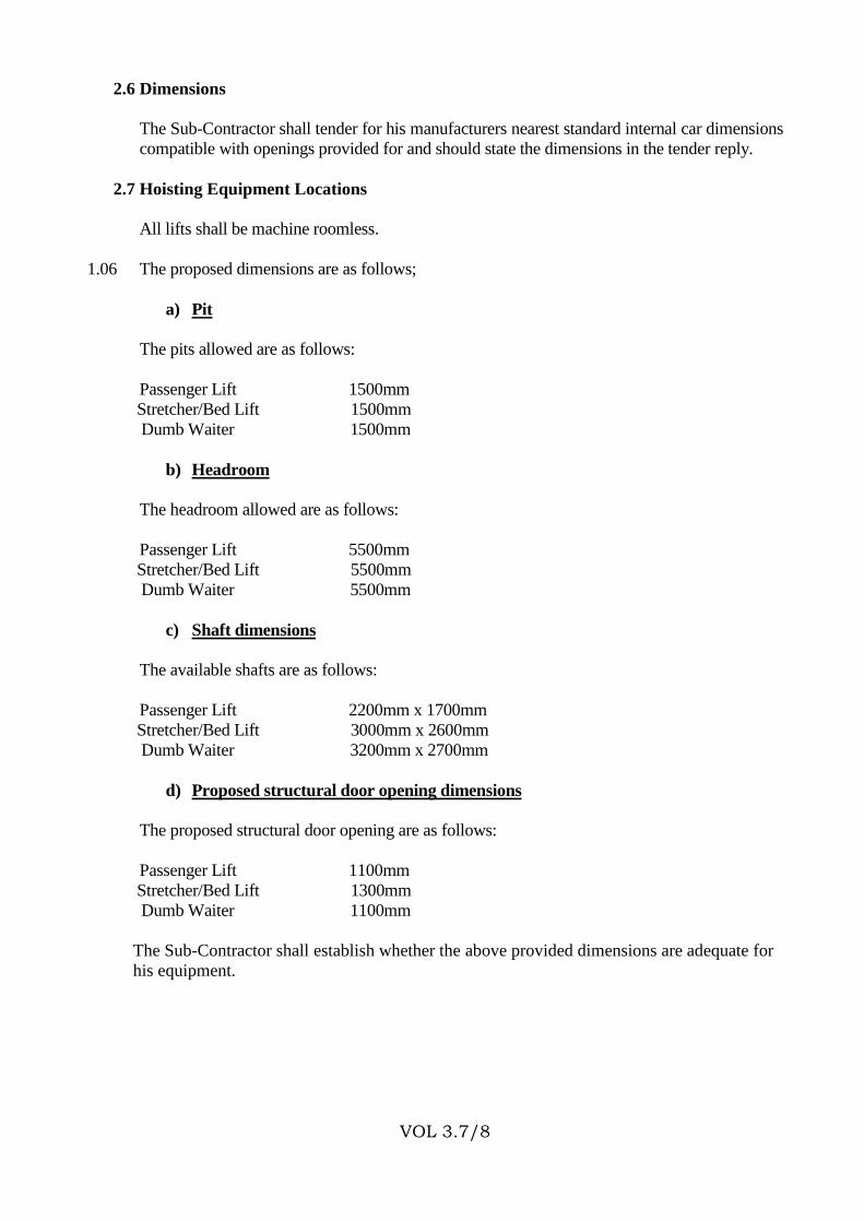
2.6 Dimensions
The Sub-Contractor shall tender for his manufacturers nearest standard internal car dimensions
compatible with openings provided for and should state the dimensions in the tender reply.
2.7 Hoisting Equipment Locations
All lifts shall be machine roomless.
1.06 The proposed dimensions are as follows;
a) Pit
The pits allowed are as follows:
Passenger Lift 1500mm
Stretcher/Bed Lift 1500mm
Dumb Waiter 1500mm
b) Headroom
The headroom allowed are as follows:
Passenger Lift 5500mm
Stretcher/Bed Lift 5500mm
Dumb Waiter 5500mm
c) Shaft dimensions
The available shafts are as follows:
Passenger Lift 2200mm x 1700mm
Stretcher/Bed Lift 3000mm x 2600mm
Dumb Waiter 3200mm x 2700mm
d) Proposed structural door opening dimensions
The proposed structural door opening are as follows:
Passenger Lift 1100mm
Stretcher/Bed Lift 1300mm
Dumb Waiter 1100mm
The Sub-Contractor shall establish whether the above provided dimensions are adequate for
his equipment.
Page 10
VOL 3.7/9
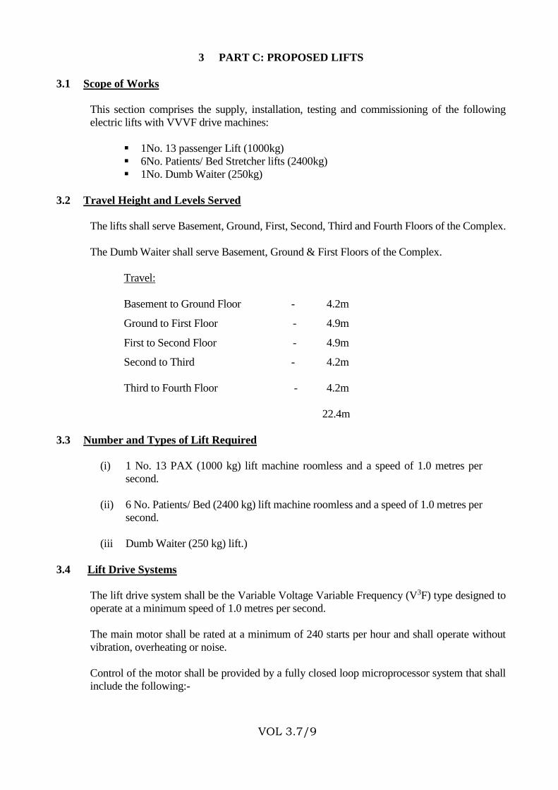
3 PART C: PROPOSED LIFTS
3.1 Scope of Works
This section comprises the supply, installation, testing and commissioning of the following
electric lifts with VVVF drive machines:
1No. 13 passenger Lift (1000kg)
6No. Patients/ Bed Stretcher lifts (2400kg)
1No. Dumb Waiter (250kg)
3.2 Travel Height and Levels Served
The lifts shall serve Basement, Ground, First, Second, Third and Fourth Floors of the Complex.
The Dumb Waiter shall serve Basement, Ground & First Floors of the Complex.
Travel:
Basement to Ground Floor - 4.2m
Ground to First Floor - 4.9m
First to Second Floor - 4.9m
Second to Third - 4.2m
Third to Fourth Floor - 4.2m
22.4m
3.3 Number and Types of Lift Required
(i) 1 No. 13 PAX (1000 kg) lift machine roomless and a speed of 1.0 metres per
second.
(ii) 6 No. Patients/ Bed (2400 kg) lift machine roomless and a speed of 1.0 metres per
second.
(iii Dumb Waiter (250 kg) lift.)
3.4 Lift Drive Systems
The lift drive system shall be the Variable Voltage Variable Frequency (V3F) type designed to
operate at a minimum speed of 1.0 metres per second.
The main motor shall be rated at a minimum of 240 starts per hour and shall operate without
vibration, overheating or noise.
Control of the motor shall be provided by a fully closed loop microprocessor system that shall
include the following:-
Page 11
VOL 3.7/10
a. A high resolution optical speed encoder, mounted direct into the motor with a
resolution of one/pulse/mm of car travel.
b. An electronic load transducer located under the car capable of detecting load
changes of 20 kg.
c. An optical position encoder connected under the car capable of detecting load
changes of 20 kg.
d. A solid state car mounted transducer to verify final floor level position to within
6mm.
The levelling accuracy shall be in the range of plus or minus 10mm and the acceleration and
deceleration shall be smooth.
The system shall continually monitor car speed, and position and compare its results with a
software based flight reference. Any error between reference and actual speed shall be corrected
within 2 milliseconds. Flight reference shall be fully programmable.
Acceleration rates shall be adjustable but when set at 1.2m/s2 shall provide the following
minimum performance:
Jerk 2.5m/s3
Levelling +/- 3mm
3 metre flight time brake 4 secs.
The following features must also be provided:
a. Motor overspeed and current protection.
b. Over current protection.
c. Over temperature protection.
d. Self Diagnostics.
e. Ability to know car position at all times even during temporary loss of mains
power.
3.5 Lift Control System
A fully micro-processor based simplex or more control system shall be provided for each lift.
Each lift shall have its own controller housed within a spray-painted sheet steel, purpose-made
cabinet. The cabinet shall be designed for front access only via lockable doors. The cabinet
doors shall be louvered for ventilation with duct filters. In addition a fan shall be fitted to ensure
air circulation.
All fuses shall be of the cartridge type although circuit breakers are preferred. Transformers shall
be floor-mounted and earthed. Relays and Contactors shall be AC3 or AC4 category as
Page 12
VOL 3.7/11
applicable and adequately rated for the job. Wire terminations shall be of the plug-in or screw
type with easy access for testing.
Micro-processor and input-output cards shall be rack mounted and self-locking through
insertion.
Short circuits, over temperature, phase failure and rope slippage detection shall all be included.
The controllers shall have the following operation control modes in its basic form: Full
collective group operation and independent service.
The control shall be fully re-programmable via a plug in test-tool. It shall be possible via this
tool to fully check all lift operations including group and safety circuits.
The system shall also have a self-diagnostic facility to speed fault location.
The control system shall be designed to EN81. BS 5655, and to be fully tested before delivery
and after installation.
3.6 Entrances
Lift cars shall have automatic high speed power-operated 2-panel centre openings sliding prime-
painted metal doors. The Tenderer shall state the exact dimensions in the quotation.
Lift landing shall have prime-painted metal architraves to the Engineer's/ Architect’s approval.
Landings shall have automatic high speed power operated 2-panel centre opening sliding painted
metal doors compatible with the lift car doors. The lift landing doors shall be a minimum of one
hour fire resistant.
3.7 Car Interior Finish
The car interior shall have synthetic resin panels which are heat-resistant and water-proof
removable panels. Pictorial brochures of finishes shall be enclosed. The floors shall be covered
with flame-resistive synthetic or granito tiles to the Engineer's approval.
A continuous stainless steel hand rail to the Engineer's approval shall be provided at a height of
950mm in each car. The rail shall be supported from the car walls at each end at no more than
750mm centres.
The rear wall of the passenger lift shall be glazed from floor level to the ceiling.
The Lifts shall have metal studs at a suitable high level to take protective cover pads which will
be used when the lift car is required to carry goods.
3.8 Car Interior Lighting
Energy-saving miniature fluorescent luminaires shall be fitted in each lift car to provide indirect
lighting. More than one tube shall be used in each lift car. The initial level of illumination at
900mm above the car floor level shall be 150 lux. The lighting shall have a metallic grid
polished prismatic diffuser or such lighting as shall be approved by the Engineer.
Page 13
VOL 3.7/12
All circuit components for the fluorescent fittings shall be mounted in separate channels or boxes
fixed on the top of each car. Capacitors shall be mounted as far as possible from chokes and in
any case not closer than 75mm.
3.9 Car Ventilation
Adequate indirect ventilation, free from draughts shall be provided in each lift car by a suitable
quiet extract fan mounted in the centre of each car roof above the suspended ceiling. An
approved fan motor isolating switch shall be provided on the top of each lift car for maintenance
purposes.
3.10 Attendant/Reservation Control
The car operating panel shall be provided with a key operated car call preference switch.
3.11 Load Non-Stop Facility
This facility shall be provided to enable fully loaded lift cars to ignore landing calls and proceed
to their destination without interruption.
3.12 Car Overload Alarm
This feature should be provided to prevent the doors of an over-loaded car from closing and
thereby prevent the dispatching of the lift car until the prescribed maximum load of the lift is
restored.
The lift car shall incorporate a load weighing and sensing device which shall become operative
when the car load exceeds 100% of the rated load.
An illuminated sign shall be placed at a suitable location near each car door and shall not be
legible until illuminated. When illuminated the sign shall read "OVERLOAD".
The car shall be provided with an audible alarm which becomes operative simultaneously with
the illuminated sign when the car is overloaded.
3.13 Nuisance Car Call Protection
This facility may be provided to minimise the abuse of the lift control system by unnecessary
multiple car calls initiated from within a lift car. This feature shall compare the load within the
lift car with the number of calls registered for a particular car, all the car calls will be
automatically cancelled thus eliminating the "nuisance" calls.
3.14 Delayed Car Protection
Car delayed by passengers preventing the doors from closing shall be rendered inoperative. The
doors of the car shall then close at minimal speed. A buzzer shall sound while the doors are thus
closing, thereby reminding passengers to get out of the way. A common buzzer shall be used for
both delayed car protection and overload alarm.
3.15 Car Operating Panel
Page 14
VOL 3.7/13
Car operating panels shall be located in each lift car and shall be flush-mounted on the right side
of the car enclosure. The individual modular units shall be mounted within a panel and shall be
suitable for ease of operation by the handicapped. The modular units shall also be printed in
Braille to assist the blind. The operating panel shall incorporate the following:-
a) A full set of micro movement call buttons corresponding to the floors served
with illuminated indication of call.
b) An alarm button painted RED.
c) Emergency stop button.
d) Door open button.
e) Door close button.
f) Ventilation fan - automatic when light on.
g) Car lighting - Automatic.
h) Emergency lighting unit.
i) Attendant/Reservation key switch.
j) Digital car position indicator.
k) Car direction indicator.
l) Overload display.
m) Interphone unit.
All illuminated call register light and Braille printed pad shall be incorporated in each
call button.
3.16 Lift Position Indicator and Signals
The lift car shall be provided with:-
a) A full set of illuminating lift position indicators over each landing entrance on
the ground floor. The lift position indicators shall incorporate directional lift
arrival indicators.
b) Illuminating directional lift arrival indicators above each landing entrance at all
served floor landings. The lift arrival indicators shall cancel on the departure of
the lift car.
c) A set of directional call button at each landing. The call buttons shall incorporate
illuminating call register lights which shall be cancelled on lift arrival.
3.17 Emergency Alarm System
Page 15
VOL 3.7/14
Each lift shall incorporate a battery operated alarm system, initiated by the ALARM push button
on each car operating panel, and wired to the common alarm bell in the ground floor lift lobby
and in intercommunication telephone system described in Clause 2.18 of this Specification. The
system shall be complete with batteries and trickle charger.
3.18 Emergency Audio Communication System
A flush mounted two-way loud-speaking instrument shall be incorporated in each lift car
operating panel. The system shall be switched into service by emergency alarm buttons which
shall incorporate an illuminating indicator lamp. The indicator lamp shall light on pressing the
emergency alarm buttons.
The audio communication system shall be included as part of the standard lift installation.
Wiring shall be provided between the emergency audio communication units via the trailing
cables to terminal blocks which shall be provided in the lift machine room.
The emergency audio communication system shall comprise:-
(a) A loud speaking instrument in the passenger carrying lift car.
(b) A wall mounted main station in the lift machine room.
(c) A desk mounted main station on the PABX telephone operator's console or at
specified main control room.
(d) An alarm extension bell above the lift landings on the ground floor lift lobby.
(e) An alkaline battery power supply and trickle charger.
(f) All necessary intercommunication wiring.
(g) All labour and materials necessary for installing and putting to work the
emergency audio communication system in compliance with the Specification.
The main station shall contain a loud speaking instrument alarm buzzer and lamps illuminated
push buttons switches for communication between the main stations.
The pressing of the alarm button in a lift car shall activate the main station alarm buzzers and
lamps, the extension alarm bell in the ground floor lift lobby and shall illuminate the push button
switches associated with the particular lift car. The alarms shall operate simultaneously at both
main stations and the ground floor lift lobby. The speech links between the lift car and a main
station shall be set up by pressing the illuminated push button switch.
3.19 The Floor Number on the Edge of the Landing Door
The floor number shall be painted on the edge of each landing door. The number shall be
readable from the inside of the lift car.
3.20 Fireman's Control
Page 16
VOL 3.7/15
The lifts shall be switched into Fireman's service mode by a toggle switch located in a
destructible box at the ground floor lift lobby. The ground floor lobby shall therefore be
designated as the "Fireman's Access Level".
The effect of activating the Fireman’s control by operating the toggle switch shall be:-
(a) Cancel all registered car calls.
(b) Force the lifts, if already travelling downwards, to proceed non-stop to the
ground floor, by-passing all registered landing calls.
(c) If the lifts are travelling upwards to force it to land at the nearest floor where the
door will remain closed. The car will reverse direction and travel non-stop to
ground floor.
(d) Force the lifts if already idle to start up and travel non-stop to the ground floor.
The cars will remain parked at the ground floor until the fireman's toggle switch is returned to
normal position.
Building Fire Alarm System activation shall automatically initiate Fireman’s service mode. The
sub-contractor shall liaise fully with Fire Detection and alarm Installer to provide the necessary
interface facilities.
3.21 Car Landing Doors
Car door operator shall be heavy duty with a design life of at least 4 million open/close cycles.
The leading edge of the car door panels shall have a full height electronic proximity sensor
system for passenger protection.
Back up operation pressure limit switches will also be provided. The operation of any of these
devices will cause the doors to reopen automatically.
Landing doors and architrave frames shall be fire proof classified to BS476 2 hour’s protection.
Page 17
VOL 3.7/16
PART C
BILLS OF QUANTITIES
Page 18
VOL 3.7/17
4 PART D: BILLS OF QUANTITIES
4.1 GENERAL NOTES TO TENDERERS
1. The Bills of Quantities form part of the contract documents and are to be read in conjunction
with the contract drawings and general specifications of materials and works.
2. The prices quoted shall be deemed to include for all obligations under the sub-contract
including but not limited to supply of materials, labour, delivery to site, storage on site,
installation, testing, commissioning (excluding 16% VAT).
3. All prices omitted from any item, section or part of the Bills of Quantities shall be
deemed to have been included to another item, section or part thereof.
4. The brief description of the items given in the Bills of Quantities are for the purpose of
establishing a standard to which the sub-contractor shall adhere. Otherwise alternative
brands of equal and approved quality will be accepted.
5. Should the sub-contractor install any material not specified here in before receiving written
approval from the Project Manager, the sub-contractor shall remove the material in
question and, at his own cost, install the proper material.
6. The grand total of prices in the price summary page must be carried forward to the Form
of Tender for the tender to be deemed valid.
7. The Bills of Quantities are divided generally into three sections:-
a. Contractual Requirements – Bill 1
Sub-contractors contractual requirements as called for the bill of quantities shall be priced and
included in the tender. However the Tenderer is free to include and price any other items he deems
necessary taking into consideration conditions he is likely to encounter on site.
b. Installation Items – Other Bills
The brief description of the items in these Bills of Quantities should in no way modify or supersede
the detailed descriptions in the contract Drawings, conditions of contract and specifications. . The
unit of measurements and observations are as per Volume 1 or as indicated in the Bills of Quantities.
c. Summary
The summary contains tabulation of the separate parts of the Bills of Quantities carried forward with
provisional sum and any prime cost sums included. This grand total tender sum shall be entered in
the Main Summary of Volume 1 provided in the Main Contractor’s document.
Page 19
VOL 3.7/18
4.2 BILLS OF QUANTITIES
SECTION D.W. 1.0 TITLE: PRELIMINARIES & CONTRACTUAL REQUIREMENTS
Item Description Unit Qty Rate KShs.
1 CONTRACTUAL REQUIREMENTS
A.
Preparation of working drawings, printing and
distribution.
Sum
B. Preparation of ‘As Installed Drawings”, printing
and distribution as specified. Drawings to
include:
(a) Blue Prints - 4 sets of each. Sum
(b) AutoCAD on CD – 2 No. Sum
(c) Operational Instructions, manuals and test
certificates
Sum
C. Allow Kshs. 4,200,000.00 Provisional sum for
overseas factory inspection to cater for 6 No.
persons (Client Rep- 1 No., SDPW Electrical
Engineer – 1 No. SDPW Technical – 1 No., User
Departments Reps – 2 No., Consulting Electrical
Engineer – 1 No.) for Lifts Sum
4,200,000.00
D. Any other item necessary to complete the
installations in this section (please state)
Sum
Total Carried to Main Summary Page
Page 20
VOL 3.7/19
SECTION D.W. 2.0 TITLE: (24 PERSONS) STRETCHER LIFT (2400KGS) LIFT SYSTEM
INSTALLATION
Item Description Unit Qty Rate KShs.
1 Stretcher Bed (2400 KGs) Lift with Variable
Voltage Variable Frequency Drive
No. 6
2 Foreign amount quoted ………………………… Sum
Exchange rate used
……………………………...
Sum
3 CIF VALUE
3.1 FOB Value in Kenya Shillings
3.2 Freight Charges
3.3 Marine Insurance………%(C+F) Sum
3.4 Bank Charges………..% (C+F) Sum
Total
4 CLEARING & FORWARDING
4.1 Customs Clearing Charges……..%(C+F) Sum
Total Sum
5 Local costs:
5.1 Local Transport Sum
5.2 Local Labour Costs Sum
5.3 Statutory Lift Inspection Sum
5.4 Clearing Agent Sum
5.5 Protection of the equipment from erratic
power
Surges. Sum
5.8 Total Local Costs Sum
Total Carried to Main Summary Page
Page 21
VOL 3.7/20
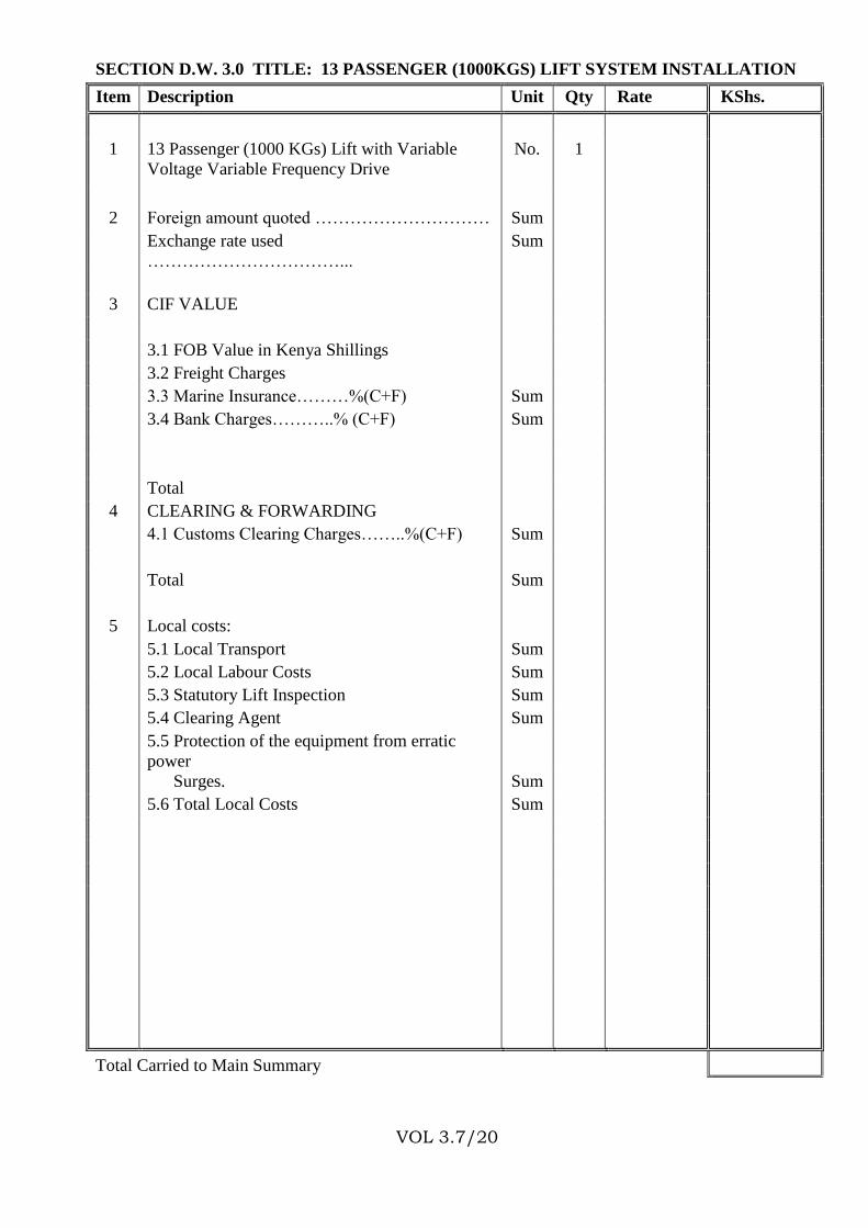
SECTION D.W. 3.0 TITLE: 13 PASSENGER (1000KGS) LIFT SYSTEM INSTALLATION
Item Description Unit Qty Rate KShs.
1 13 Passenger (1000 KGs) Lift with Variable
Voltage Variable Frequency Drive
No. 1
2 Foreign amount quoted ………………………… Sum
Exchange rate used
……………………………...
Sum
3 CIF VALUE
3.1 FOB Value in Kenya Shillings
3.2 Freight Charges
3.3 Marine Insurance………%(C+F) Sum
3.4 Bank Charges………..% (C+F) Sum
Total
4 CLEARING & FORWARDING
4.1 Customs Clearing Charges……..%(C+F) Sum
Total Sum
5 Local costs:
5.1 Local Transport Sum
5.2 Local Labour Costs Sum
5.3 Statutory Lift Inspection Sum
5.4 Clearing Agent Sum
5.5 Protection of the equipment from erratic
power
Surges. Sum
5.6 Total Local Costs Sum
Total Carried to Main Summary
Page 22
VOL 3.7/21
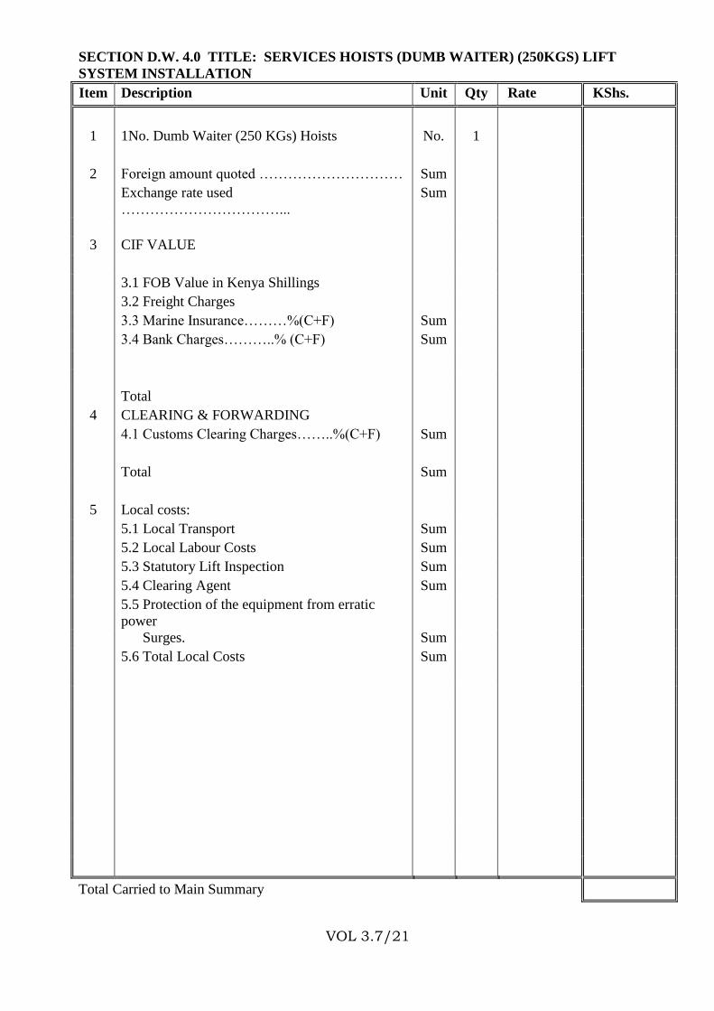
SECTION D.W. 4.0 TITLE: SERVICES HOISTS (DUMB WAITER) (250KGS) LIFT
SYSTEM INSTALLATION
Item Description Unit Qty Rate KShs.
1 1No. Dumb Waiter (250 KGs) Hoists No. 1
2 Foreign amount quoted ………………………… Sum
Exchange rate used
……………………………...
Sum
3 CIF VALUE
3.1 FOB Value in Kenya Shillings
3.2 Freight Charges
3.3 Marine Insurance………%(C+F) Sum
3.4 Bank Charges………..% (C+F) Sum
Total
4 CLEARING & FORWARDING
4.1 Customs Clearing Charges……..%(C+F) Sum
Total Sum
5 Local costs:
5.1 Local Transport Sum
5.2 Local Labour Costs Sum
5.3 Statutory Lift Inspection Sum
5.4 Clearing Agent Sum
5.5 Protection of the equipment from erratic
power
Surges. Sum
5.6 Total Local Costs Sum
Total Carried to Main Summary
Page 23
VOL 3.7/22
THE SUPPLY, DELIVERY, INSTALLATION, TESTING AND COMMISSIONING OF
ELEVATOR SYSTEMS INSTALLATIONS
MAIN SUMMARY OF PRICES
Item Description Unit Qty Rate KShs.
DW
1.0
SECTION 1
Preliminaries & Contractual Requirements
DW
2.0
SECTION 2
Stretcher Bed (2400 KGs) System
DW
3.0
SECTION 3
13 Passenger (1000 KGs) System
DW
4.0
SECTION 4
1 No. Dumb Waiter (250 KGs) System
Sub Total
Total Carried Forward to Main Summary of Volume I
Page 24
VOL 3.7/23
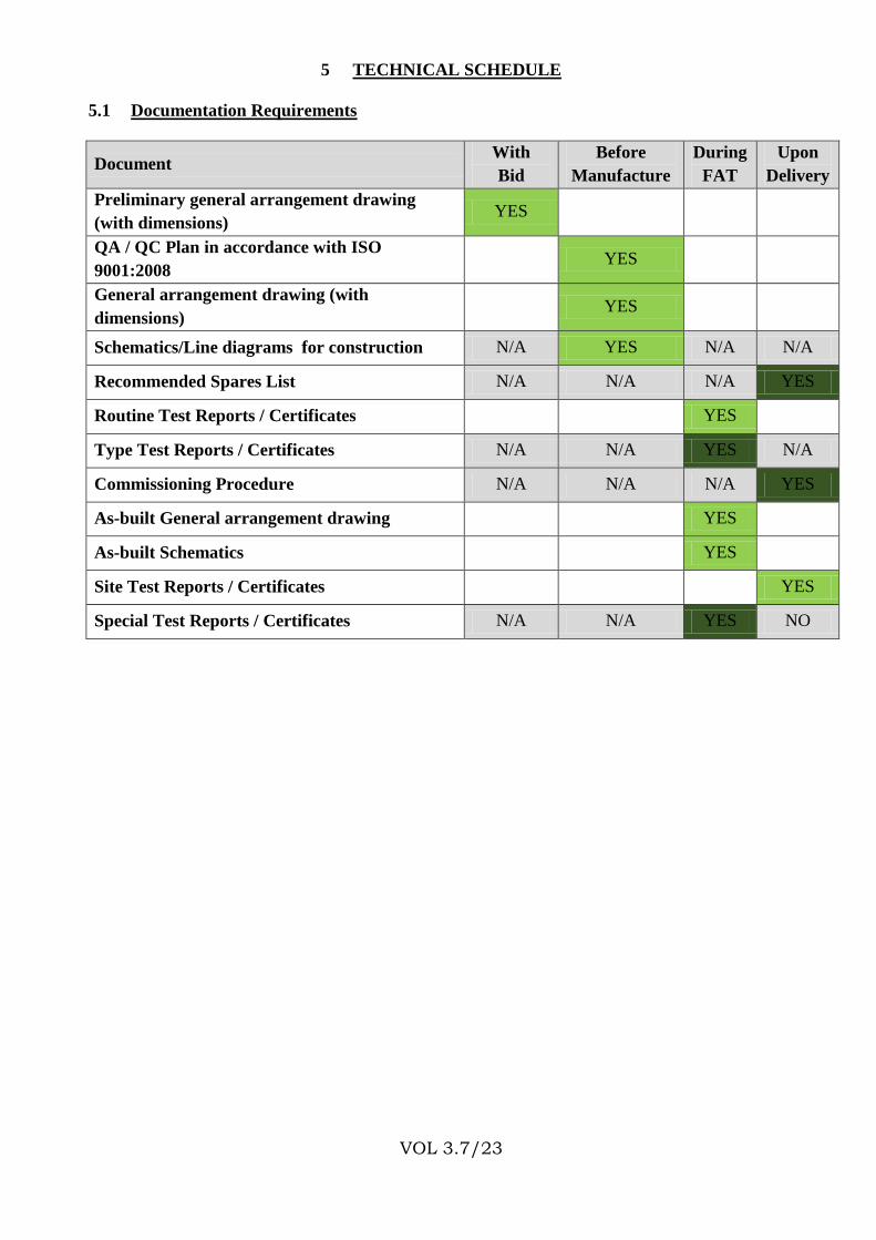
5 TECHNICAL SCHEDULE
5.1 Documentation Requirements
Document With
Bid
Before
Manufacture
During
FAT
Upon
Delivery
Preliminary general arrangement drawing
(with dimensions) YES
QA / QC Plan in accordance with ISO
9001:2008 YES
General arrangement drawing (with
dimensions) YES
Schematics/Line diagrams for construction N/A YES N/A N/A
Recommended Spares List N/A N/A N/A YES
Routine Test Reports / Certificates YES
Type Test Reports / Certificates N/A N/A YES N/A
Commissioning Procedure N/A N/A N/A YES
As-built General arrangement drawing YES
As-built Schematics YES
Site Test Reports / Certificates YES
Special Test Reports / Certificates N/A N/A YES NO
Page 25
VOL 3.7/24
5.2 Technical Schedule
The tenderer MUST SUBMIT comprehensive manufacturer’s technical brochures and performance
details for all items listed in this schedule (fill forms attached).
ITEM No. Description Remarks
A
B
C
Stretcher Bed Lifts
Passenger Lifts
Dumbwaiter
Page 26
VOL 3.7/25
6 DRAWING SCHEDULE
6.1 DRAWING SCHEDULE:
As shall be provided during project implementation.