16
Model NOZ Indirectly fired air heaters
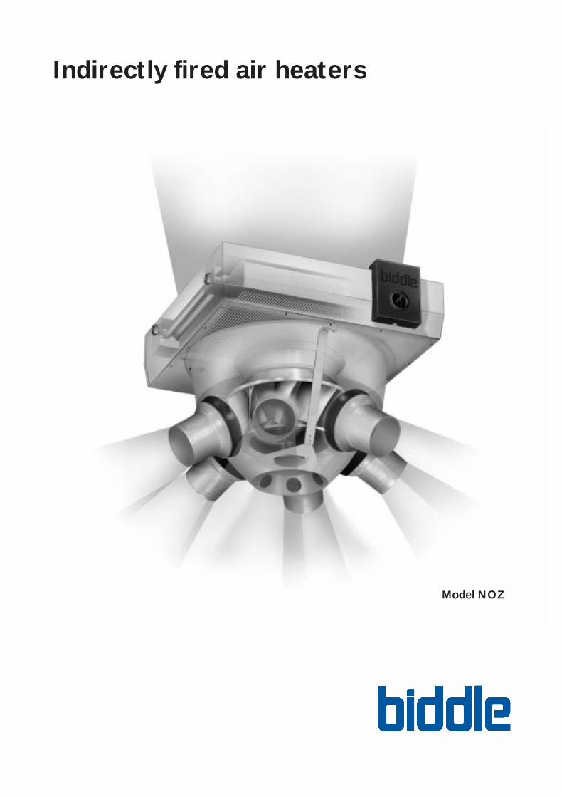
Model NOZ
Indirectly fired air heaters
Biddle nozzlebroch eng•247256 22-04-2004 15:39PM Pagina 3

Indirectly fired air heatersAir heaters are fit for heating and/or ventilating large-space industrial andcommercial buildings. The Biddle air heater, model NOZ, can be applied inrooms of 4 to 16 metres high. The fast and even distribution of heat makesthis ceiling model fit for use in, for instance, DIY markets, factory buildings,distribution centres and warehouses.
If there is a need for fresh air in a room, the air heater may also be used forventilation purposes. Accessories for that are available from Biddle (see page 3).
Induction
The air heater has individually adjustable nozzles, thus providing a better distribution of the air. Warm air is discharged downward through the nozzles in adjustable directions.The air flow draws the surroundingstill air along, resulting in goodmixing (induction). This makes thatthe warm air will spread across alarge area quickly and evenly. To calculate the air circulationratio, an air induction ratio of 2 (low speed) to 4 (high speed) may be taken.
Various options
The air heater is available in two types: the NOZ 25 and the NOZ 50.The unit comes, as a standard, with a 2-row heating battery that is suitablefor water temperatures of 90/70°C. At lower water temperatures or in situations where more heating capacity is needed, a 3-row heating battery is available. The type code is obtained by choosing one option from eachcolumn. An instance of a type code is NOZ 25–W2-D.
Benefits of indirectly fired air heatersinclude:
• No flue gas discharge• Hardly any maintenance• Safe• Relatively low investment• Eye-catching design
Type code
NOZ 25-W2-D
NOZ = air heater with nozzles
25 / 50 = nominal heatingcapaciteit kW
W2 = standard 2-rowheating battery
W3 = 3-row heating batteryfor lower water temperature ranges
E = 230 VoltsD = 400 Volts
2
Type Heating battery Supply voltage
NOZ 25 W2 = 2-row heating battery E (230 Volts, AC, 50 Hz)W3 = 3-row heating battery D (400 Volts, AC, 50 Hz)
NOZ 50 W2 = 2-row heating battery D (400 Volts, AC, 50 Hz)W3 = 3-row heating battery
Biddle nozzlebroch eng•247256 22-04-2004 15:39PM Pagina 4

Installation
The air heater can be suspended anywhere in the room. Thanks to the adjustable nozzles, stands or racks form no obstacles to a free flow of air.The recommended mounting height is 3 - 14 m, measured from the bottom of the unit.
There are two mounting options:1. With a suspension frame (available as an accessory), to which four threaded
ends are fixed with nuts. The nuts fit into purpose-made “keyholes”. 2. Without a suspension frame, use being made of four M8 threaded ends.
Guard grille
For safety reasons, each nozzle comes standard with a guard grille.
Accessories
Biddle supplies various additional accessories.
• control switch: 2 or 5 speeds (see page 6)• water-temperature control: for regulating the discharged air temperature• room thermostat and thermostat with frost protection• suspension frame: for fast and simple mounting• plastic covers (2): to cover up nozzles.
Accessories, ventilation model
• aluminium vent cap and roof vent flange• duct sections: 0.5 or 1 metre long • filter module: filter class G2• damper module: operated using the corresponding valve motor
(with or without spring return)
There are 2 types:
1. 1-way damper module: used with 100% ventilation, so no draught or heatloss occurs when the air heater is off.
2. 3-way damper module: used if not only outside air but also inside air is drawn in (recirculation). Thus, the ratio between these air flows may be influenced.
Suspension frame makes mountingeasy.
3
Guard grille
Biddle nozzlebroch eng•247256 22-04-2004 15:39PM Pagina 5
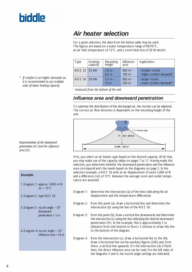
Air heater selectionFor a quick selection, the data from the below table may be used. The figures are based on a water temperature range of 90/70°C, an air inlet temperature of 15°C, and a room heat loss of 20 Watts/m3.
Type Heating- Mounting- Influence- Applicationcapacity height1 area
NOZ 25 25 kW 2.8 m - 400 m2 - - smaller rooms8.5 m 100 m2 - higher comfort demands*
NOZ 50 50 kW 3.5 m - 800 m2 - - larger rooms14 m 200 m2 - lower comfort demands*
1 measured from the bottom of the unit
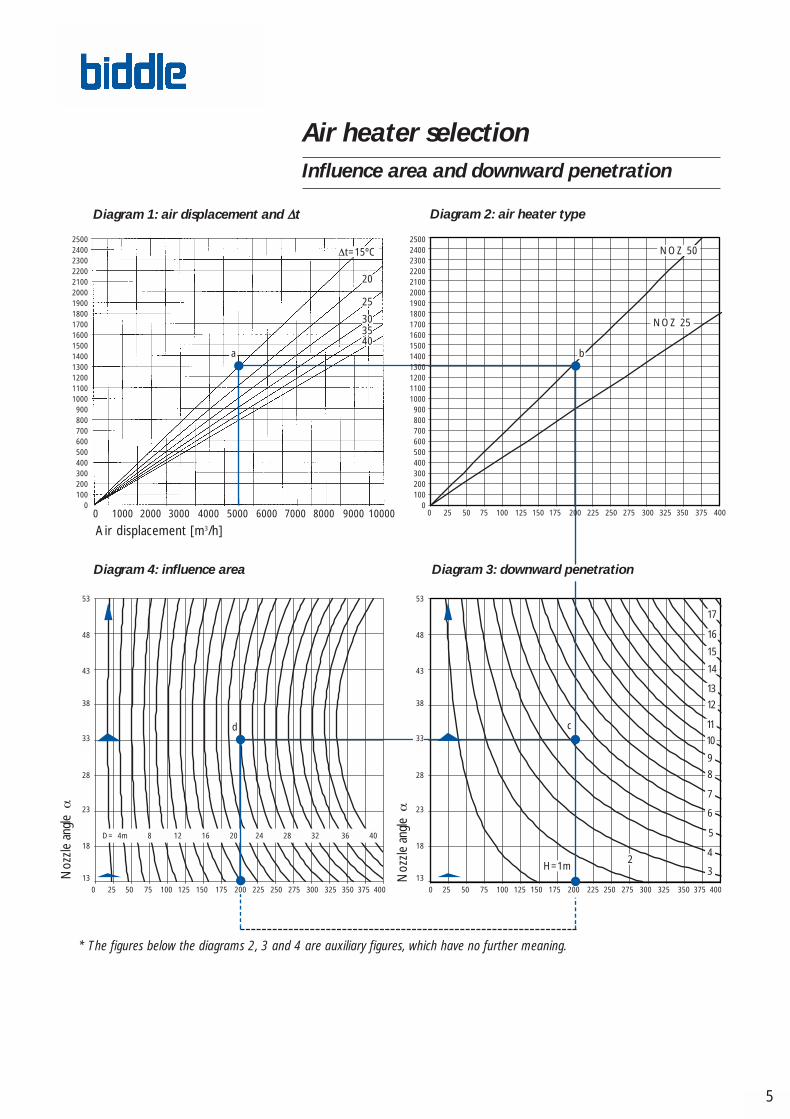
Influence area and downward penetration
To optimise the distribution of the discharged air, the nozzles can be adjusted.The correct air flow direction is dependent on the mounting height of theunit.
First, you select an air heater type based on the desired capacity. With that,you may make use of the capacity tables on pages 7 to 11. Having made thisselection, you determine whether the downward penetration and the influencearea correspond with the needs based on the diagrams on page 5. In theselection example, a NOZ 50 with an air displacement of some 5,000 m3/hand a difference (∆t) of 15°C between the average room and outlet tempe-rature are assumed.
Diagram 1: determine the intersection (a) of the lines indicating the air displacement and the temperature differential.
Diagram 2: from this point (a), draw a horizontal line and determine theintersection (b) using the line of the NOZ 50.
Diagram 3: from this point (b), draw a vertical line downwards and determinethe intersection (c) using the line indicating the desired downwardpenetration (H). In the example, this is approximately 5 m(distance from unit bottom to floor). Continue to draw this lineto the bottom of the diagram.
Diagram 4: from the intersection (c), draw a horizontal line to the left,draw a horizontal line via the auxiliary figures (200) and, fromthere, a vertical line upwards. On the intersection (d) of bothlines, the direct influence area can be read. On the left sides ofthe diagrams 3 and 4, the nozzle angle settings are indicated.
* If comfort is set higher demands on, it is recommended to use multiple units of lower heating capacity.
Representation of the downward penetration (H) and the influence area (D).
D 800 - 100 m2
3.0 - 14.0 m
Example
1.Diagram 1: approx. 5000 m3/h∆t = 15°C
2.Diagram 2: type NOZ 50
3.Diagram 3: nozzle angle = 33ºdownward penetration = 5 m
4.Diagram 4: nozzle angle = 33°influence area =24 m
4
Biddle nozzlebroch eng•247256 22-04-2004 15:39PM Pagina 6
Air displacement [m3/h]
5
0 0 25 50 75 100 125 150 250 275 300 3251000 2000 3000 4000 5000 6000 7000 8000 9000 10000
∆t=15ºC NOZ 50
NOZ 25
403530
25
20
0 25 50 75 100 125 150
D= 4m 8 12 16 20 24 28 32 36 40
13
18
23
28
38
43
48
53
Noz
zle a
ngle
α
H=1m
14
13
12
9
8
7
6
4
3
175
175
33
5
d c
a b
2500240023002200210020001900180017001600150014001300120011001000900800700600500400300200100
0
2500240023002200210020001900180017001600150014001300120011001000900800700600500400300200100
0200 225 350 375 400
200 225 250 275 300 325 350 375 400
10
11
15
16
17
13
18
23
28
38
43
48
53
33
0 25 50 75 100 125 150 175 225 250 275 300 325 350 375 400200
2
Diagram 1: air displacement and ∆t Diagram 2: air heater type
Diagram 3: downward penetrationDiagram 4: influence area
Noz
zle a
ngle
α
* The figures below the diagrams 2, 3 and 4 are auxiliary figures, which have no further meaning.
Air heater selectionInfluence area and downward penetration
Biddle nozzlebroch eng•247256 22-04-2004 15:39PM Pagina 7
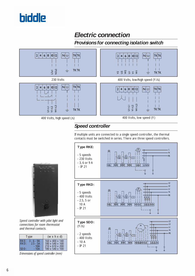
Electric connectionProvisions for connecting isolation switch
Speed controller
If multiple units are connected to a single speed controller, the thermal contacts must be switched in series. There are three speed controllers.
6
Dimensions of speed controller (mm)
Type (w x h x d)RKE: 3 - 6 - 9A 160 x 400 x 140RKD: 2.5 - 5A 180 x 540 x 100
- 10A 210 x 610 x 200SDD: - 10A 180 x 540 x 100
Speed controller with pilot light andconnections for room thermostat and thermal contacts.
Type RKE:
- 5 speeds- 230 Volts - 3, 6 or 9 A- IP 21
230 Volts
400 Volts, low speed (Y)400 Volts, high speed (∆)
400 Volts, low/high speed (Y/∆)
Type RKD:
- 5 speeds- 400 Volts - 2.5, 5 or 10 A
- IP 21
Type SDD: (Y/∆)
- 2 speeds- 400 Volts- 10 A- IP 21
Biddle nozzlebroch eng•247256 22-04-2004 15:39PM Pagina 8
7
* tLi = air inlet temperature** Air displacement is less with ventilation models - if 1 module is used, by 15% and as a whole, by 20%.
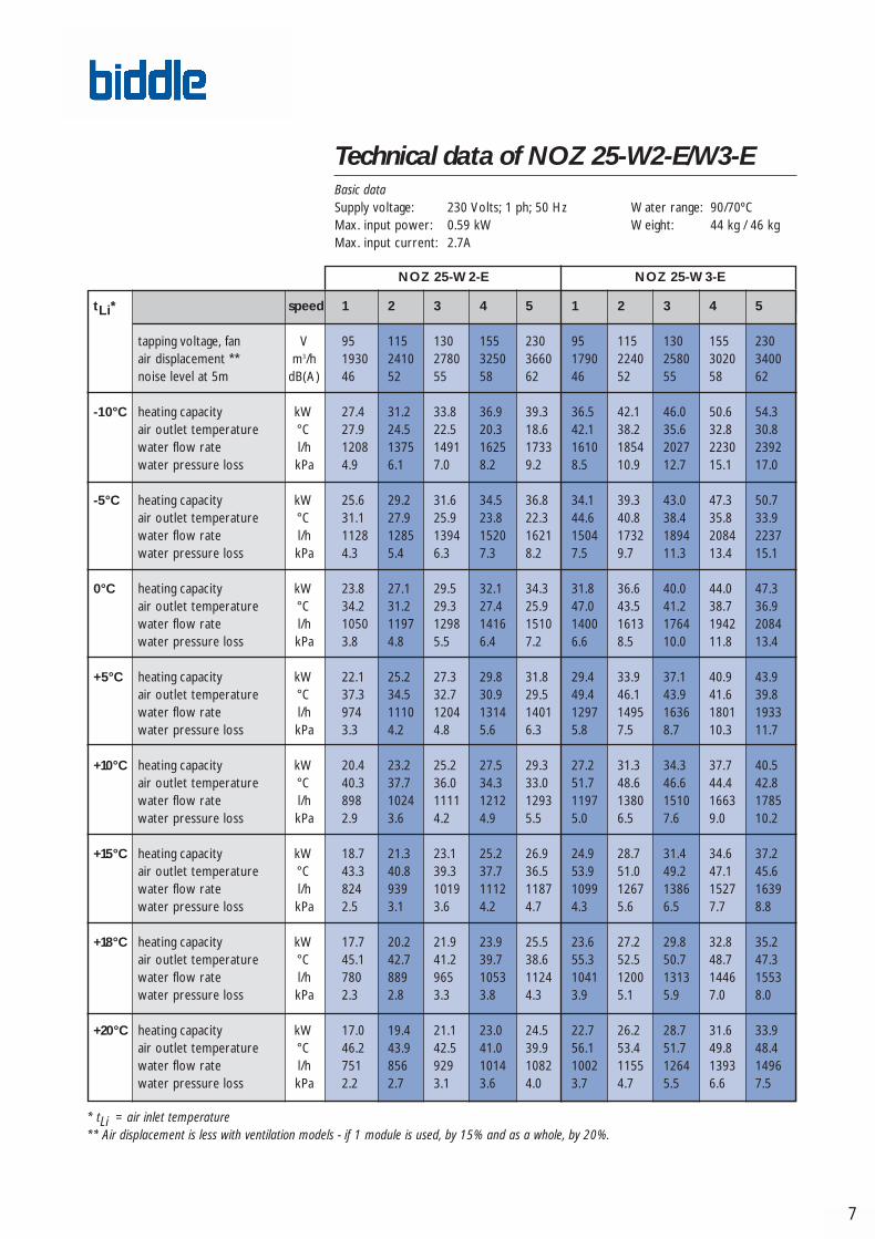
Technical data of NOZ 25-W2-E/W3-EBasic dataSupply voltage: 230 Volts; 1 ph; 50 Hz Water range: 90/70ºCMax. input power: 0.59 kW Weight: 44 kg / 46 kgMax. input current: 2.7A
tLi* speed 1 2 3 4 5 1 2 3 4 5
tapping voltage, fan V 95 115 130 155 230 95 115 130 155 230air displacement ** m3/h 1930 2410 2780 3250 3660 1790 2240 2580 3020 3400noise level at 5m dB(A) 46 52 55 58 62 46 52 55 58 62
-10°C heating capacity kW 27.4 31.2 33.8 36.9 39.3 36.5 42.1 46.0 50.6 54.3air outlet temperature °C 27.9 24.5 22.5 20.3 18.6 42.1 38.2 35.6 32.8 30.8water flow rate l/h 1208 1375 1491 1625 1733 1610 1854 2027 2230 2392water pressure loss kPa 4.9 6.1 7.0 8.2 9.2 8.5 10.9 12.7 15.1 17.0
-5°C heating capacity kW 25.6 29.2 31.6 34.5 36.8 34.1 39.3 43.0 47.3 50.7air outlet temperature °C 31.1 27.9 25.9 23.8 22.3 44.6 40.8 38.4 35.8 33.9water flow rate l/h 1128 1285 1394 1520 1621 1504 1732 1894 2084 2237water pressure loss kPa 4.3 5.4 6.3 7.3 8.2 7.5 9.7 11.3 13.4 15.1
0°C heating capacity kW 23.8 27.1 29.5 32.1 34.3 31.8 36.6 40.0 44.0 47.3air outlet temperature °C 34.2 31.2 29.3 27.4 25.9 47.0 43.5 41.2 38.7 36.9water flow rate l/h 1050 1197 1298 1416 1510 1400 1613 1764 1942 2084water pressure loss kPa 3.8 4.8 5.5 6.4 7.2 6.6 8.5 10.0 11.8 13.4
+5°C heating capacity kW 22.1 25.2 27.3 29.8 31.8 29.4 33.9 37.1 40.9 43.9air outlet temperature °C 37.3 34.5 32.7 30.9 29.5 49.4 46.1 43.9 41.6 39.8water flow rate l/h 974 1110 1204 1314 1401 1297 1495 1636 1801 1933water pressure loss kPa 3.3 4.2 4.8 5.6 6.3 5.8 7.5 8.7 10.3 11.7
+10°C heating capacity kW 20.4 23.2 25.2 27.5 29.3 27.2 31.3 34.3 37.7 40.5air outlet temperature °C 40.3 37.7 36.0 34.3 33.0 51.7 48.6 46.6 44.4 42.8water flow rate l/h 898 1024 1111 1212 1293 1197 1380 1510 1663 1785water pressure loss kPa 2.9 3.6 4.2 4.9 5.5 5.0 6.5 7.6 9.0 10.2
+15°C heating capacity kW 18.7 21.3 23.1 25.2 26.9 24.9 28.7 31.4 34.6 37.2air outlet temperature °C 43.3 40.8 39.3 37.7 36.5 53.9 51.0 49.2 47.1 45.6water flow rate l/h 824 939 1019 1112 1187 1099 1267 1386 1527 1639water pressure loss kPa 2.5 3.1 3.6 4.2 4.7 4.3 5.6 6.5 7.7 8.8
+18°C heating capacity kW 17.7 20.2 21.9 23.9 25.5 23.6 27.2 29.8 32.8 35.2air outlet temperature °C 45.1 42.7 41.2 39.7 38.6 55.3 52.5 50.7 48.7 47.3water flow rate l/h 780 889 965 1053 1124 1041 1200 1313 1446 1553water pressure loss kPa 2.3 2.8 3.3 3.8 4.3 3.9 5.1 5.9 7.0 8.0
+20°C heating capacity kW 17.0 19.4 21.1 23.0 24.5 22.7 26.2 28.7 31.6 33.9air outlet temperature °C 46.2 43.9 42.5 41.0 39.9 56.1 53.4 51.7 49.8 48.4water flow rate l/h 751 856 929 1014 1082 1002 1155 1264 1393 1496water pressure loss kPa 2.2 2.7 3.1 3.6 4.0 3.7 4.7 5.5 6.6 7.5
NOZ 25-W2-E NOZ 25-W3-E
Biddle nozzlebroch eng•247256 22-04-2004 15:39PM Pagina 9

8
* tLi = air inlet temperature** Air displacement is less with ventilation models - if 1 module is used, by 15% and as a whole, by 20%.
Technical data of NOZ 25-W2-DBasic dataSupply voltage: 400 Volts; 3 ph; 50 Hz Water range: 90/70ºCMax. input power: 0.54 kW Weight: 42 kgMax. input current: 1.1A
tLi* 1 2 3 4 5 1 2 3 4 5
tapping voltage, fan V 155 195 240 300 400 155 195 240 300 400air displacement ** m3/h 1150 1440 1760 2210 2770 1940 2400 2810 3280 3680noise level at 5 m dB(A) 33 38 43 49 54 45 50 55 59 61
-10°C heating capacity kW 19.9 22.9 25.9 29.7 33.8 27.5 31.3 34.0 37.1 39.4air outlet temperature °C 36.1 32.5 29.3 25.8 22.5 27.8 24.6 22.3 20.1 18.6water flow rate l/h 876 1011 1143 1308 1488 1211 1371 1500 1633 1738water pressure loss kPa 2.8 3.6 4.4 5.6 7.0 4.9 6.1 7.1 8.3 9.2
-5°C heating capacity kW 18.6 21.4 24.2 27.7 31.6 25.7 29.1 31.8 34.7 36.9air outlet temperature °C 38.9 35.4 32.4 29.1 26.0 31.0 27.9 25.8 23.7 22.2water flow rate l/h 818 944 1068 1222 1391 1132 1282 1402 1528 1625water pressure loss kPa 2.4 3.2 3.9 5.0 6.2 4.3 5.4 6.3 7.4 8.2
0°C heating capacity kW 17.3 19.9 22.5 25.8 29.4 23.9 27.1 29.6 32.3 34.4air outlet temperature °C 41.6 38.3 35.5 32.3 29.4 34.1 31.2 29.2 27.3 25.9water flow rate l/h 761 878 994 1138 1296 1054 1194 1306 1423 1515water pressure loss kPa 2.2 2.8 3.5 4.4 5.5 3.8 4.8 5.6 6.5 7.2
+5°C heating capacity kW 16.0 18.5 20.9 23.9 27.3 22.2 25.1 27.5 29.9 31.9air outlet temperature °C 44.2 41.2 38.5 35.5 32.7 37.2 34.5 32.6 30.7 29.4water flow rate l/h 705 8 921 1055 1202 977 1107 12 1320 1405water pressure loss kPa 1.9 2.4 3.0 3.8 4.8 3.3 4.2 4.9 5.7 6.3
+10°C heating capacity kW 14.7 17.0 19.3 22.1 25.2 20.4 23.2 25.4 27.6 29.4air outlet temperature °C 46.8 43.9 41.4 38.7 36.1 40.2 37.7 35.9 34.2 33.0water flow rate l/h 650 751 849 973 1109 901 1021 1118 1218 1297water pressure loss kPa 1.6 2.1 2.6 3.3 4.2 2.9 3.6 4.2 4.9 5.5
+15°C heating capacity kW 13.5 15.6 17.7 20.3 23.1 18.8 21.3 23.5 25.4 27.0air outlet temperature °C 49.3 46.7 44.3 41.8 39.3 43.2 40.9 39.2 37.6 36.4water flow rate l/h 596 688 779 893 1017 827 937 1026 1118 1190water pressure loss kPa 1.4 1.8 2.2 2.9 3.6 2.5 3.1 3.6 4.2 4.7
+18°C heating capacity kW 12.8 14.8 16.7 19.2 21.8 17.7 20.1 22.0 24.0 25.6air outlet temperature °C 50.8 48.3 46.0 43.6 41.3 45.0 42.7 41.1 39.6 38.5water flow rate l/h 564 652 737 845 963 782 887 971 1058 1127water pressure loss kPa 1.3 1.6 2.0 2.6 3.3 2.3 2.8 3.3 3.9 4.3
+20°C heating capacity kW 12.3 14.2 16.1 18.5 21.0 17.1 19.4 21.2 23.1 24.6air outlet temperature °C 51.8 49.4 47.2 44.8 42.6 46.2 44.0 42.4 40.9 39.9water flow rate l/h 543 627 710 814 927 753 854 935 1019 1085water pressure loss kpa 1.2 1.5 1.9 2.4 3.1 2.1 2.6 3.1 3.6 4.0
Speed (Y-connection) Speed (∆-connection)
Biddle nozzlebroch eng•247256 22-04-2004 15:39PM Pagina 10

9
* tLi = air inlet temperature** Air displacement is less with ventilation models - if 1 module is used, by 15% and as a whole, by 20%.
Technical data of NOZ 25-W3-DBasic dataSupply voltage: 400 Volts; 3 ph; 50 Hz Water range: 90/70ºCMax. input power: 0.54 kW Weight: 44 kgMax. input current: 1.1A
tLi* 1 2 3 4 5 1 2 3 4 5
tapping voltage, fan V 155 195 240 300 400 155 195 240 300 400air displacement ** m3/h 1060 1330 1630 2050 2570 1800 2230 2610 3050 3420noise level at 5 m dBA 33 38 43 49 54 45 50 55 58 61
-10°C heating capacity kW 24.8 29.1 33.4 38.8 44.7 35.6 40.9 45.1 49.6 53.1air outlet temperature °C 52.3 48.3 44.6 40.5 36.4 42.8 38.9 36.1 33.4 31.4water flow rate l/h 1091 1281 1470 1709 1971 1571 1803 1990 2187 2341water pressure loss kPa 4.3 5.7 7.2 9.4 12.1 8.1 10.4 12.3 14.6 16.4
-5°C heating capacity kW 23.1 27.1 31.1 36.2 41.8 33.3 38.2 42.2 46.4 49.6air outlet temperature °C 54.2 50.4 46.9 43.0 39.2 45.3 41.6 38.9 36.6 34.5water flow rate l/h 1018 1196 1373 1596 1842 1467 1685 1859 2045 2188water pressure loss kPa 3.8 5.0 6.4 8.4 10.8 7.2 9.2 10.9 12.9 14.6
0°C heating capacity kW 21.5 25.2 29.0 33.7 38.9 31.0 35.6 39.3 43.2 46.3air outlet temperature °C 56.1 52.5 49.2 45.5 41.9 47.6 44.2 41.7 39.2 37.5water flow rate l/h 947 1112 1278 1486 1715 1365 1568 1731 1904 2039water pressure loss kPa 3.3 4.4 5.6 7.4 9.5 6.3 8.1 9.6 11.4 12.9
+5°C heating capacity kW 19.9 23.4 26.9 31.3 36.1 28.7 33.0 36.4 40.1 42.9air outlet temperature °C 57.9 54.6 51.5 48.0 44.6 50.0 46.7 44.4 42.0 40.4water flow rate l/h 877 1030 1184 1378 1590 1265 1454 1606 1766 1891water pressure loss kPa 2.9 3.9 4.9 6.5 8.3 5.6 7.1 8.4 10.0 11.3
+10°C heating capacity kW 18.4 21.6 24.8 28.8 33.3 26.5 30.4 33.6 37.0 39.6air outlet temperature °C 59.7 56.5 53.6 50.4 47.2 52.2 49.2 47.0 44.8 43.3water flow rate l/h 809 950 1092 1271 1468 1167 1342 1482 1631 1746water pressure loss kPa 2.5 3.4 4.3 5.6 7.2 4.8 6.2 7.3 8.7 9.8
+15°C heating capacity kW 16.8 19.8 22.7 26.5 30.6 24.3 27.9 30.9 34.0 36.4air outlet temperature °C 61.4 58.5 55.8 52.7 49.7 54.4 51.6 49.5 47.5 46.1water flow rate l/h 742 872 1003 1167 1347 1071 1232 1360 1497 1604water pressure loss kPa 2.2 2.9 3.7 4.8 6.2 4.1 5.3 6.3 7.5 8.4
+18°C heating capacity kW 15.9 18.7 21.5 25.1 28.9 23.0 26.5 29.2 32.2 34.5air outlet temperature °C 62.4 59.6 57.0 54.1 51.2 55.7 53.0 51.1 49.1 47.7water flow rate l/h 703 826 950 1105 1276 1015 1167 1288 1418 1519water pressure loss kPa 2.0 2.6 3.4 4.4 5.6 3.8 4.8 5.7 6.8 7.7
+20°C heating capacity kW 15.4 18.0 20.7 24.1 27.9 22.2 25.5 28.2 31.0 33.2air outlet temperature °C 63.0 60.3 57.8 55.0 52.2 56.6 54.0 52.1 50.2 48.8water flow rate l/h 677 795 914 1064 1229 977 1123 1241 1366 1463water pressure loss kPa 1.8 2.5 3.1 4.1 5.3 3.5 4.5 5.4 6.4 7.2
Speed (Y-connection) Speed (∆-connection)
Biddle nozzlebroch eng•247256 22-04-2004 15:39PM Pagina 11

10
* tLi = air inlet temperature** Air displacement is less with ventilation models - if 1 module is used, by 15% and as a whole, by 20%.
Technical data of NOZ 50-W2-DBasic dataSupply voltage: 400 Volts; 3 ph; 50 Hz Water range: 90/70ºCMax. input power: 1.35 kW Weight: 69 kgMax. input current: 2.4 A
tLi* 1 2 3 4 5 1 2 3 4 5
tapping voltage, fan V 155 195 240 300 400 155 195 240 300 400air displacement ** m3/h 2570 3180 3990 4950 6740 4550 5540 6780 7780 8930noise level at 5 m dBA 37 44 49 54 60 52 57 61 64 66
-10°C heating capacity kW 42.4 48.4 55.4 62.8 74.6 59.9 66.9 74.8 80.5 85.4air outlet temperature °C 34.0 30.6 27.1 23.9 19.5 25.1 22.2 19.4 17.6 16.1water flow rate l/h 1868 2132 2444 2769 3287 2638 2951 3297 3548 3766water pressure loss kPa 2.3 2.8 3.6 4.5 6.1 4.1 5.0 6.1 7.0 7.7
-5°C heating capacity kW 39.6 45.2 51.8 58.7 69.7 55.9 62.6 69.9 75.3 79.9air outlet temperature °C 36.8 33.6 30.3 27.2 23.1 28.4 25.7 23.0 21.3 19.9water flow rate l/h 1744 1992 2283 2588 3073 2466 2758 3003 3318 3523water pressure loss kPa 2.0 2.5 3.2 4.0 5.4 3.7 4.5 5.4 6.2 6.9
0°C heating capacity kW 36.8 42.0 48.2 54.7 64.9 52.1 58.3 65.2 70.1 74.5air outlet temperature °C 39.6 36.6 33.5 30.6 26.7 31.7 29.1 26.6 25.0 23.6water flow rate l/h 1622 1853 2125 2410 2863 2295 2569 2872 3091 3283water pressure loss kPa 1.8 2.2 2.8 3.5 4.8 3.2 3.9 4.8 5.5 6.1
+5°C heating capacity kW 34.1 39.0 34.7 50.7 60.2 48.3 54.0 60.4 65.0 69.1air outlet temperature °C 42.4 39.5 36.6 33.9 30.2 34.9 32.5 30.1 28.6 27.3water flow rate l/h 1502 1717 1969 2234 2655 2127 2382 2663 2876 3046water pressure loss kPa 1.5 1.9 2.6 3.1 4.2 2.8 3.5 4.2 4.8 5.3
+10°C heating capacity kW 31.4 35.9 41.2 46.7 55.6 44.5 49.8 55.8 60.0 63.8air outlet temperature °C 45.1 42.4 39.6 37.1 33.7 38.1 35.8 33.6 32.1 31.0water flow rate l/h 1385 1583 1816 2060 2450 1962 2197 2458 2646 2811water pressure loss kPa 1.3 1.7 2.1 2.7 3.6 2.5 3.0 3.6 4.2 4.6
+15°C heating capacity kW 28.8 32.9 37.8 42.9 51.0 40.8 45.7 51.1 55.1 58.5air outlet temperature °C 47.7 45.3 42.7 40.3 37.1 41.2 39.1 37.0 35.7 34.6water flow rate l/h 1270 1452 1665 1889 2247 1799 2015 2254 2428 2579water pressure loss kPa 1.1 1.4 1.8 2.3 3.1 2.1 2.6 3.1 3.6 4.0
+18°C heating capacity kW 27.3 31.2 35.8 40.6 48.2 38.6 43.3 48.4 52.1 55.4air outlet temperature °C 49.3 46.9 44.4 42.2 39.1 43.1 41.0 39.1 37.8 36.7water flow rate l/h 1201 1374 1576 1788 2127 1703 1907 2133 2298 2441water pressure loss kPa 1.0 1.3 1.7 2.1 2.8 1.9 2.3 2.8 3.2 3.6
+20°C heating capacity kW 26.2 30.0 34.4 39.0 46.4 37.2 41.6 46.6 50.2 53.3air outlet temperature °C 50.3 48.0 45.6 43.4 40.5 44.3 42.3 40.4 39.2 38.1water flow rate l/h 1156 1322 1517 1721 2047 1639 1835 2053 2212 2350water pressure loss kPa 1.0 1.2 1.6 1.9 2.6 1.8 2.2 2.7 3.0 3.4
Speed (Y-connection) Speed (∆-connection)
Biddle nozzlebroch eng•247256 22-04-2004 15:39PM Pagina 12
11
* tLi = air inlet temperature** Air displacement is less with ventilation models - if 1 module is used, by 15% and as a whole, by 20%.
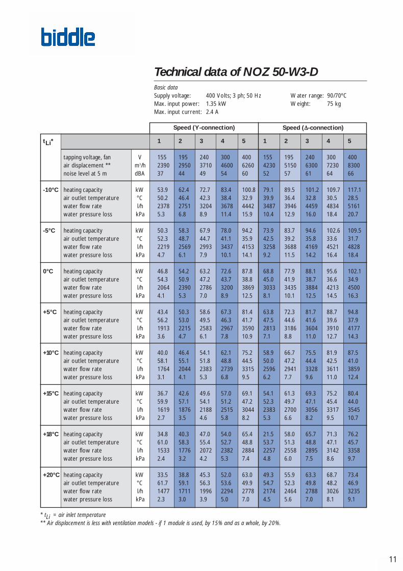
Technical data of NOZ 50-W3-DBasic dataSupply voltage: 400 Volts; 3 ph; 50 Hz Water range: 90/70ºCMax. input power: 1.35 kW Weight: 75 kgMax. input current: 2.4 A
tLi* 1 2 3 4 5 1 2 3 4 5
tapping voltage, fan V 155 195 240 300 400 155 195 240 300 400air displacement ** m3/h 2390 2950 3710 4600 6260 4230 5150 6300 7230 8300noise level at 5 m dBA 37 44 49 54 60 52 57 61 64 66
-10°C heating capacity kW 53.9 62.4 72.7 83.4 100.8 79.1 89.5 101.2 109.7 117.1air outlet temperature °C 50.2 46.4 42.3 38.4 32.9 39.9 36.4 32.8 30.5 28.5water flow rate l/h 2378 2751 3204 3678 4442 3487 3946 4459 4834 5161water pressure loss kPa 5.3 6.8 8.9 11.4 15.9 10.4 12.9 16.0 18.4 20.7
-5°C heating capacity kW 50.3 58.3 67.9 78.0 94.2 73.9 83.7 94.6 102.6 109.5air outlet temperature °C 52.3 48.7 44.7 41.1 35.9 42.5 39.2 35.8 33.6 31.7water flow rate l/h 2219 2569 2993 3437 4153 3258 3688 4169 4521 4828water pressure loss kPa 4.7 6.1 7.9 10.1 14.1 9.2 11.5 14.2 16.4 18.4
0°C heating capacity kW 46.8 54.2 63.2 72.6 87.8 68.8 77.9 88.1 95.6 102.1air outlet temperature °C 54.3 50.9 47.2 43.7 38.8 45.0 41.9 38.7 36.6 34.9water flow rate l/h 2064 2390 2786 3200 3869 3033 3435 3884 4213 4500water pressure loss kPa 4.1 5.3 7.0 8.9 12.5 8.1 10.1 12.5 14.5 16.3
+5°C heating capacity kW 43.4 50.3 58.6 67.3 81.4 63.8 72.3 81.7 88.7 94.8air outlet temperature °C 56.2 53.0 49.5 46.3 41.7 47.5 44.6 41.6 39.6 37.9water flow rate l/h 1913 2215 2583 2967 3590 2813 3186 3604 3910 4177water pressure loss kPa 3.6 4.7 6.1 7.8 10.9 7.1 8.8 11.0 12.7 14.3
+10°C heating capacity kW 40.0 46.4 54.1 62.1 75.2 58.9 66.7 75.5 81.9 87.5air outlet temperature °C 58.1 55.1 51.8 48.8 44.5 50.0 47.2 44.4 42.5 41.0water flow rate l/h 1764 2044 2383 2739 3315 2596 2941 3328 3611 3859water pressure loss kPa 3.1 4.1 5.3 6.8 9.5 6.2 7.7 9.6 11.0 12.4
+15°C heating capacity kW 36.7 42.6 49.6 57.0 69.1 54.1 61.3 69.3 75.2 80.4air outlet temperature °C 59.9 57.1 54.1 51.2 47.2 52.3 49.7 47.1 45.4 44.0water flow rate l/h 1619 1876 2188 2515 3044 2383 2700 3056 3317 3545water pressure loss kPa 2.7 3.5 4.6 5.8 8.2 5.3 6.6 8.2 9.5 10.7
+18°C heating capacity kW 34.8 40.3 47.0 54.0 65.4 21.5 58.0 65.7 71.3 76.2air outlet temperature °C 61.0 58.3 55.4 52.7 48.8 53.7 51.3 48.8 47.1 45.7water flow rate l/h 1533 1776 2072 2382 2884 2257 2558 2895 3142 3358water pressure loss kPa 2.4 3.2 4.2 5.3 7.4 4.8 6.0 7.5 8.6 9.7
+20°C heating capacity kW 33.5 38.8 45.3 52.0 63.0 49.3 55.9 63.3 68.7 73.4air outlet temperature °C 61.7 59.1 56.3 53.6 49.9 54.7 52.3 49.8 48.2 46.9water flow rate l/h 1477 1711 1996 2294 2778 2174 2464 2788 3026 3235water pressure loss kPa 2.3 3.0 3.9 5.0 7.0 4.5 5.6 7.0 8.1 9.1
Speed (Y-connection) Speed (∆-connection)
Biddle nozzlebroch eng•247256 22-04-2004 15:39PM Pagina 13

Heating capacity different water temperatures.
12
Explanation of technical data
Heating capacity
The heating capacities stated in the tables on pages 7 to 11 are based on awater temperature range of 90/70°C and an air inlet temperature of 15°C. If water temperatures differ, the heating capacity is to be multiplied by thecorrection factors from the table below.
Air inlet temperature
Water range -10°C -5°C 0°C +5°C +10°C +15°C +18°C +20°C
110/90 °C 1.82 1.72 1.63 1.53 1.44 1.35 1.29 1.26
100/80 °C 1.64 1.54 1.45 1.36 1.27 1.17 1.12 1.09
90/70 °C 1.46 1.37 1.27 1.18 1.09 1 0.95 0.91
80/60 °C 1.28 1.19 1.09 1.00 0.91 0.82 0.77 0.74
70/50 °C 1.09 1.00 0.91 0.82 0.73 0.65 0.60 0.56
60/40 °C 0.91 0.82 0.73 0.64 0.56 0.47 0.42 0.39
With the ventilation model, air displacement decreases (due to modules andductwork). The following guideline may be used:
• 1 module = 15 % less than the table values • 2 modules and ductwork = 20 % less than the table values
A decrease in air displacement also leads to a decrease in heating capacity.Using the formula, you may calculate the new heating capacity.
• 1 module = Qnew = 0.93 • Qtable value
• 2 modules and ductwork = Qnew = 0.90 • Qtable value
Water flow rate
The water flow rates stated in the tables on pages 7 to 11 are based on awater temperature range of 90-70°C. If water temperatures differ, the water flow rate may be roughly calculated using the below formula.Before doing so, the heating capacity must first be recalculated (see above).
If circumstances differ from thosedescribed here, such as different watertemperatures or more than one unit ina single room, please do not hesitateto ask for our advice.
mw = water flow rate [l/h]Q = heating capacity [kW] (see the above table)ρw = density of water at 90ºC (=0.984) [kg/l]
cpw = specific heat of water (=4.18)
∆Tw = water temperature differential [ºC]
kJ
kgºC
mw = • 3600 [ l /h] Q
ρw cpw ∆Tw
Biddle nozzlebroch eng•247256 22-04-2004 15:39PM Pagina 14

13
Explanation of technical data
Water pressure loss
The water pressure loss stated in the tables on pages 7 to 11 is based on awater temperature range of 90/70°C. If water temperatures differ, the waterpressure loss may be roughly calculated using the below formula. Beforedoing so, the water flow rate must first be recalculated (see page 12).
Sound
The sound data represented on pages 7 to 11 were measured at a distanceof 5 m from the unit, in a room with a reverberation time of 1.2 seconds and with a volume according to the below table. With these room volumes,the air circulation ratio in the room is 1 at fan speed 5.
Type Connection Room volume
NOZ 25-E - 3660 m3
NOZ 25-D Y 2770 m3
NOZ 25-D ∆ 3680 m3
NOZ 50-D Y 6740 m3
NOZ 50-D ∆ 8930 m3
For distances other than 5 m, the below correction factors must be appliedto the sound pressure values stated in the tables on pages 7 to 11.
Correction factors for sound pressure level, in dB(A) (for all fan speeds)
Distance
Type Connection 3 m 4 m 5 m 6 m 8 m 10 m
NOZ 25-E - +1.7 +0.6 0 -0.4 -0.9 -1.1
NOZ 25-D Y +1.5 +0.6 0 -0.3 -0.6 -0.8
NOZ 25-D ∆ +1.8 +0.7 0 -0.4 -0.8 -1.0
NOZ 50-D Y +2.5 +1.0 0 -0.5 -1.2 -1.6
NOZ 50-D ∆ +2.7 +1.1 0 -0.7 -1.5 -1.9
∆ pw2= water pressure loss
∆ pw1= water pressure loss, table values
mw1 = water flow rate, table values
mw2 = water flow ratem calculated using formula on pag. 12
∆pw2=∆pw1
• mw1(mw2)
2
Biddle nozzlebroch eng•247256 22-04-2004 15:39PM Pagina 15
14
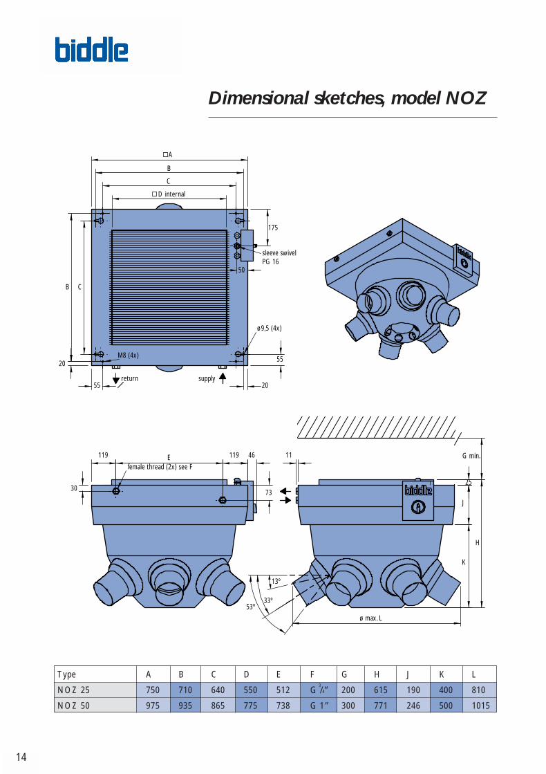
Dimensional sketches, model NOZ
Type A B C D E F G H J K L
NOZ 25 750 710 640 550 512 G3/4” 200 615 190 400 810
NOZ 50 975 935 865 775 738 G 1” 300 771 246 500 1015
D internal
C
B
A
175
sleeve swivelPG 16
50
B C
20
55 20
M8 (4x) 55
return supply
ø9,5 (4x)
119 119 46 11
3073
female thread (2x) see F
G min.
25
J
H
K
53º
ø max. L
13º
33º
E
Biddle nozzlebroch eng•247256 22-04-2004 15:40PM Pagina 16
15
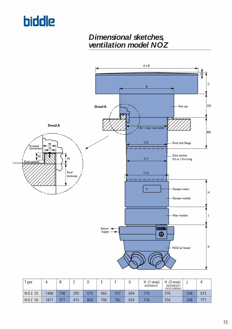
Dimensional sketches, ventilation model NOZ
Type A B C D E F G H (1-way) H (3-way) J K
NOZ 25 1406 746 295 575 565 557 604 176 376 248 615
NOZ 50 1871 971 415 800 790 782 829 176 556 248 771
ventilation/recirculation
ventilation
Biddle nozzlebroch eng•247256 22-04-2004 15:40PM Pagina 17
NO
Z-E
NG
-200
4-04
•247
256
Specifications
Casing
The casing is made of zinc plated sheet steel, extra strengthened to minimisevibration, and it has an inspection panel in the side. The casing and guard grillecome, as a standard, in the colour RAL 9018 (light grey), the inspection paneland the plastic rings in RAL 5010 (blue). The nozzles are made of natural alu-minium. Other RAL colours are available at an extra charge.
Heating battery
The 2- or 3-row heating battery is made up of 3/8” copper pipes and aluminium fins. The water connections for the NOZ 25 are G
3/4” and for
the NOZ 50 G1”. These connections (internally secured against torsion) are located in the side of the unit.
Test pressure : 30 bar Max. operating pressure : 16 bar at 120°C
Motor / Fan assembly
The diagonal fan is made up of an aluminium impeller and an external rotormotor. The fan speed can be controlled by varying the supply voltage. The motor is according to DIN 40050, belongs to protection class IP 54 and meets the standard DIN VDE 0530. Insulation class: B.
If overheated, the motor is protected by thermal contacts, which will breakthe electric circuit.
Thermostat with frost protection
The air heater may be fitted with a built-in thermostat with frost protection.At temperatures below 6°C, the thermostat will send out a signal to thevalve motor.
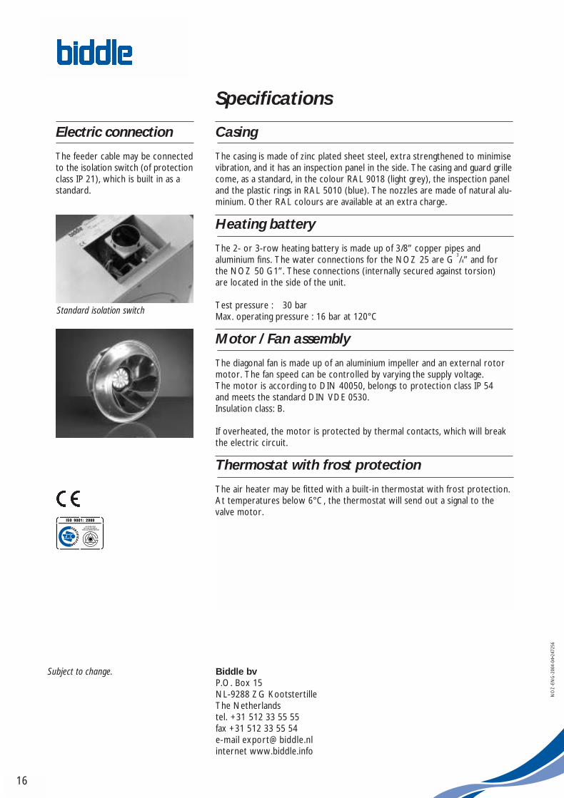
Electric connection
The feeder cable may be connectedto the isolation switch (of protectionclass IP 21), which is built in as astandard.
Biddle bvP.O. Box 15NL-9288 ZG KootstertilleThe Netherlandstel. +31 512 33 55 55fax +31 512 33 55 54e-mail [email protected] www.biddle.info
Subject to change.
16
Standard isolation switch
Biddle nozzlebroch eng•247256 22-04-2004 15:39PM Pagina 2


