Billiards: A 2-dimensional mechanical analog to Rutherford scattering Some lower division undergraduate physics labs include a 2-D “billiards” experiment which is analogous to the Rutherford scattering experiment you will be performing in physics 122. Of course some of the details are different! This document is from one such lower division lab.
Transcript
Billiards: A 2-dimensional mechanical analog to Rutherford scattering
Some lower division undergraduate physics labs include a 2-D “billiards” experiment which is
analogous to the Rutherford scattering experiment you will be performing in physics 122. Of
course some of the details are different! This document is from one such lower division lab.
Nobel Experiment Exp. 3, Particle Scattering 2
Particle Scattering
Table of Contents
Nobel Prize Note 3
1. Hard-Sphere Model of Atomic ScatteringLaboratory Experiment
IntroductionTheory
Theory of Hard Sphere Collisions 3Theory for the Experiment 11Apparatus 13Procedure 13
2. Differential Cross Section in 2-DHard Sphere Model of Atomic Scattering
Lord Earnest Rutherford was awarded the Nobel Prize in 1908 for his "investigations in regardto the decay of elements and the chemistry of radioactive substances."
He was a talented, hard-working physicist with enormous drive and self-confidence. In a letterwritten later in life, he wrote, "I've been reading some of my early papers and, you know, when I'dfinished, I said to myself, "Rutherford, my boy, you used to be a damned clever fellow." Thoughpleased at winning a Nobel Prize he was not happy that it was a chemistry prize, rather than one inphysics. In his speech accepting the prize he noted that he had observed many transformations in hiswork with radioactivity but never had seen one as rapid as his own, from physicist to chemist.
HARD-SPHERE MODEL OF ATOMIC SCATTERING
LABORATORY EXPERIMENT
Introduction
This apparatus is designed to acquaint the user with some of the mechanics of scattering ofatomic particles by using analogous objects of large dimensions. The diameter of a target isdetermined from data supplied by the scatter pattern of projectiles deflected by it.
Scattering experiments analogous to this simple mechanical one are most useful in many areasof physics. Much knowledge of nuclei, electrons, protons, neutrons and alpha particles and observingwhat occurs at different angles. By so doing, definite quantitative conclusions about the scatters areobtained although they cannot actually be seen. Of course a single particle is never fired at aparticular scatterer using a predetermined impact parameter, as is done in this experiment, but rather alarge number of particles bombard the target and the desired information is obtained from the relativenumber scattered at a given angle.
Nobel Experiment Exp. 3, Particle Scattering 4
Theory
Theory of Hard Sphere Collisions
The energy transfer between colliding hard spheres can take place by either elastic or inelasticscattering. In a collision where there is energy transfer but the kinetic energy is conserved, thiscollision is classified as being perfectly elastic. In an elastic collision particles transfer kinetic energydetermined by the laws of conservation of momentum and kinetic energy.If the colliding particles transfer energy to some other form of energy than kinetic energy then thisleaves the bombarding particle and target particle with less energy to share. This interaction is calledinelastic, and the kinetic energy for the colliding particles is not conserved, however, theconservation of momentum is conserved in the inelastic collision. The collisions between manyparticles in a system can be considered to occur at random. The probability that one particle suffers acollision with some other particle during any small time interval is thus assumed to be independent ofits history of past collisions. The mean time tau (τ) which the particle travels before suffering its nextcollision is called the mean free time of the particle. The mean distance λ which the particle travelsbefore suffering its next collision is called the mean free path of the particle. If the particle has somemean speed υ, then the mean free path λ and the mean free time τ are related by
λ=υτ
where the velocity of the particle is measured relative to the laboratory frame of reference. This is notthe relative velocity between the particles and is not measured relative to the atoms. The mean timebetween collisions tau τ will be determined using the relative velocity between the bombardingparticles and the target particles.
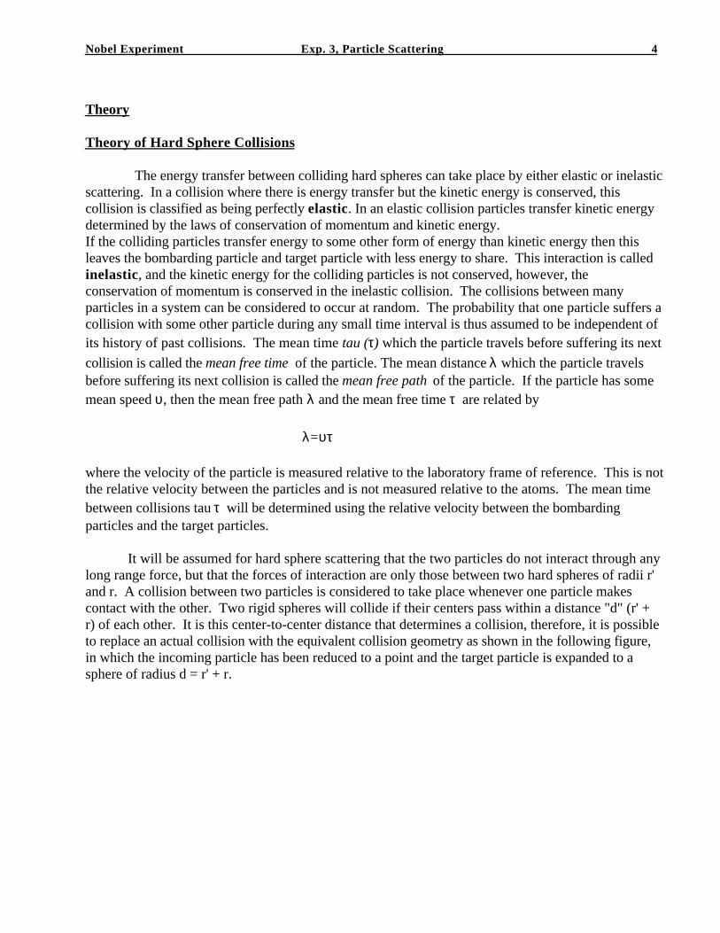
It will be assumed for hard sphere scattering that the two particles do not interact through anylong range force, but that the forces of interaction are only those between two hard spheres of radii r'and r. A collision between two particles is considered to take place whenever one particle makescontact with the other. Two rigid spheres will collide if their centers pass within a distance "d" (r' +r) of each other. It is this center-to-center distance that determines a collision, therefore, it is possibleto replace an actual collision with the equivalent collision geometry as shown in the following figure,in which the incoming particle has been reduced to a point and the target particle is expanded to asphere of radius d = r' + r.
Nobel Experiment Exp. 3, Particle Scattering 5
r r'
Hard Sphere Collision
r' + r
Equivalent Collision
A bombarding particle with and equivalent diameter "d" which travels a long distance L will sweepout a volume
V = πd2 L
where the equivalent collision area πd2 is called the collision cross sectional area sigma (σ). Thescattering cross section will collide with any other particle whose center lies within the volume. If nis the concentration of target particles, the average number of particles in this volume is
N = nσL
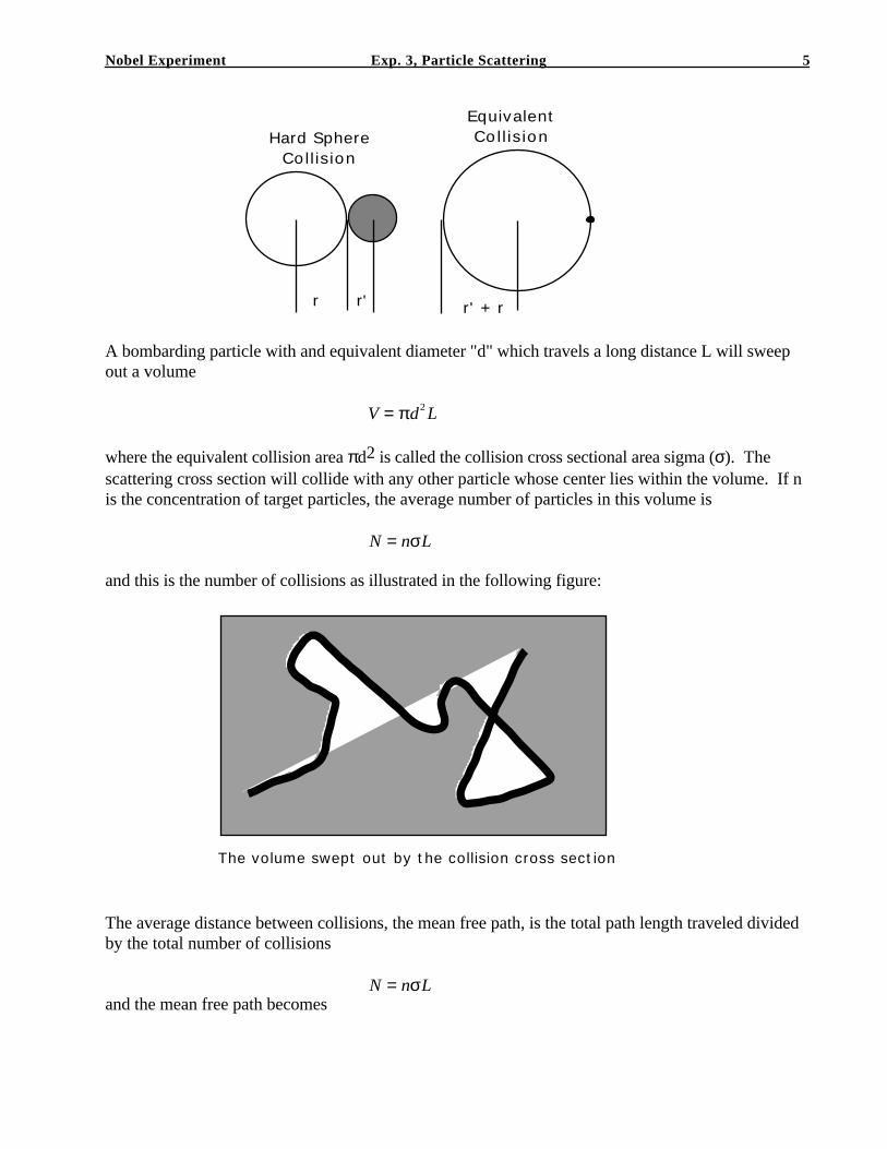
and this is the number of collisions as illustrated in the following figure:
The volume swept out by the collision cross section
The average distance between collisions, the mean free path, is the total path length traveled dividedby the total number of collisions
N = nσLand the mean free path becomes
Nobel Experiment Exp. 3, Particle Scattering 6
λ =1
nσ⋅⋅⋅ where ⋅ ⋅ ⋅ σ = πd2 .
Therefore the mean free path is small when the number of target particles per unit volume is large,there are more particles for which the bombarding particle can collide, and the mean free path is alsosmall when the diameter of the target particle is large, the bombarding particle is more likely tointeract with a target particle.
In the above derivation for the mean free path of the bombarding particle it was assumed that thetarget particles are at rest relative to the incoming particles. This is not true in general, since both thebombarding particle and the target particles move, their relative mean speed V is different from themean speed v of an individual particle. If these velocities are taken into consideration the mean freepath for the bombarding particles becomes:
λ =v
V rel
1
nσ
where the relative velocity of between the bombarding particle and the target particle is given by
r V =
r v − ′
r v .
The above result is obtained from the following derivation. The definition of the mean freepath of the electrons is:
λ = v τ
where v bar is the mean speed of the electrons relative to the tube. This is not measured relative tothe atoms. The mean time between collisions tau will take care of the velocities of the atoms asfollows.
The two particle collision interaction can be replaced by the equivalent scattering cross sectionsigma (σ). As this scattering cross section moves through out the volume of target particles it willsweep out a volume. All target particles within this volume will have a collision. This scatteringcross section will move at a velocity that must be measured relative to the target particles and is givenby
r V =
r v − ′
r v
where v is the velocity of the bombarding particle and v' is the velocity of the target particles.
The volume swept out by the scattering cross section σin a time "t" is
Vol = σL
where L is given by L = V relt and Vrel =r V =
r v − ′
r v
Nobel Experiment Exp. 3, Particle Scattering 7
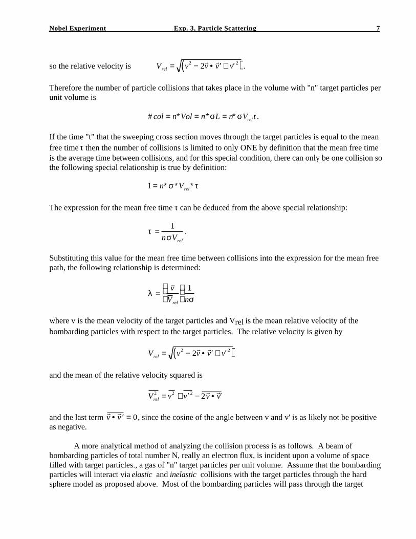
so the relative velocity is Vrel = v2 − 2r v • ′
r v + ′ v 2( ) .
Therefore the number of particle collisions that takes place in the volume with "n" target particles perunit volume is
# col = n∗Vol = n∗σL = n∗σVrel t .
If the time "t" that the sweeping cross section moves through the target particles is equal to the meanfree time τ then the number of collisions is limited to only ONE by definition that the mean free timeis the average time between collisions, and for this special condition, there can only be one collision sothe following special relationship is true by definition:
1 = n∗σ ∗Vrel∗τ
The expression for the mean free time τ can be deduced from the above special relationship:
τ =1
nσVrel
.
Substituting this value for the mean free time between collisions into the expression for the mean freepath, the following relationship is determined:
λ =v
V rel
1
nσ
where v is the mean velocity of the target particles and Vrel is the mean relative velocity of thebombarding particles with respect to the target particles. The relative velocity is given by
Vrel = v2 − 2r v • ′
r v + ′ v 2( )
and the mean of the relative velocity squared is
Vrel2 = v2 + ′ v 2 − 2
r v • ′
r v
and the last term r v • ′
r v = 0, since the cosine of the angle between v and v' is as likely not be positive
as negative.
A more analytical method of analyzing the collision process is as follows. A beam ofbombarding particles of total number N, really an electron flux, is incident upon a volume of spacefilled with target particles., a gas of "n" target particles per unit volume. Assume that the bombardingparticles will interact via elastic and inelastic collisions with the target particles through the hardsphere model as proposed above. Most of the bombarding particles will pass through the target
Nobel Experiment Exp. 3, Particle Scattering 8
particle gas, but some will have elastic and inelastic collisions and these collisions will remove some ofbombarding particles δN from the incoming particle beam.
Consider a thin layer of target particles of area A by δx. The ratio of the number of collisions,δN, to the total number of incident particles, N, is equal to the ratio of the total scattering crosssection area to the covered area of the thin layer volume:
δNN
=ScatteringCrossSectionArea
T arg etArea
δx
L
TargetParticles
ScatteredBombardingParticlesBombarding
Particles
N(x)TransmittedParticles
N0
N0-N
A
A
The equivalent scattering cross section area of one target particle is:
σ = π ( ′ r + r )2
The total collision cross section is the product of this and the number of target particles in the thinlayer:
# = nAδx
The total area of the thin target layer covered by the incident particles is also just A, so
δN
N= nσδx
where δN / N is the fraction number of bombarding particles that have collisions with the targetparticles and are removed from the electron beam, therefore, this ratio does represent the probabilityof a collision.
Nobel Experiment Exp. 3, Particle Scattering 9
If N0 bombarding particles per unit area are incident normally on the face of a layer of material
containing target particles at rest with a total scattering cross section "nσ", then the number N oftransmitted bombarding particles per unit area through a finite thickness "x" will be given by
−δN
N
N0
N
∫ = nσδx0
x
∫ ,
integrating to give the number of bombarding particles along the scattering distance x:
N = N0e− nσx
which results in an exponential decrease in bombarding particles with distance into the target volume.
The number of bombarding particles that collide with target particles is δN in the distance δx,therefore, the total ranges of the bombarding particles in this group is just δN*δx. The averagedistance traveled by the bombarding particles will be the sum of the combined ranges of all groupsfrom N0 to 0 divided by the total number of bombarding particles, which is
x = λ =
xdNN0
0
∫
dNN0
0
∫
The number of bombarding particles as a function of "x" is given above
N = N0e− nσx
and the derivative dN is given by
dN = −N0 nσe− nσxdx .
The integral for the mean free path becomes:
λ = nσ xe −nσxdx0
∞
∫
which can be integrated to obtain the expression for the mean free path
λ =1
nσ
Nobel Experiment Exp. 3, Particle Scattering 10
where n is the number of target particles per unit volume and σ is the equivalent scattering crosssection for hard sphere scattering.
Nobel Experiment Exp. 3, Particle Scattering 11
Theory for the Experiment
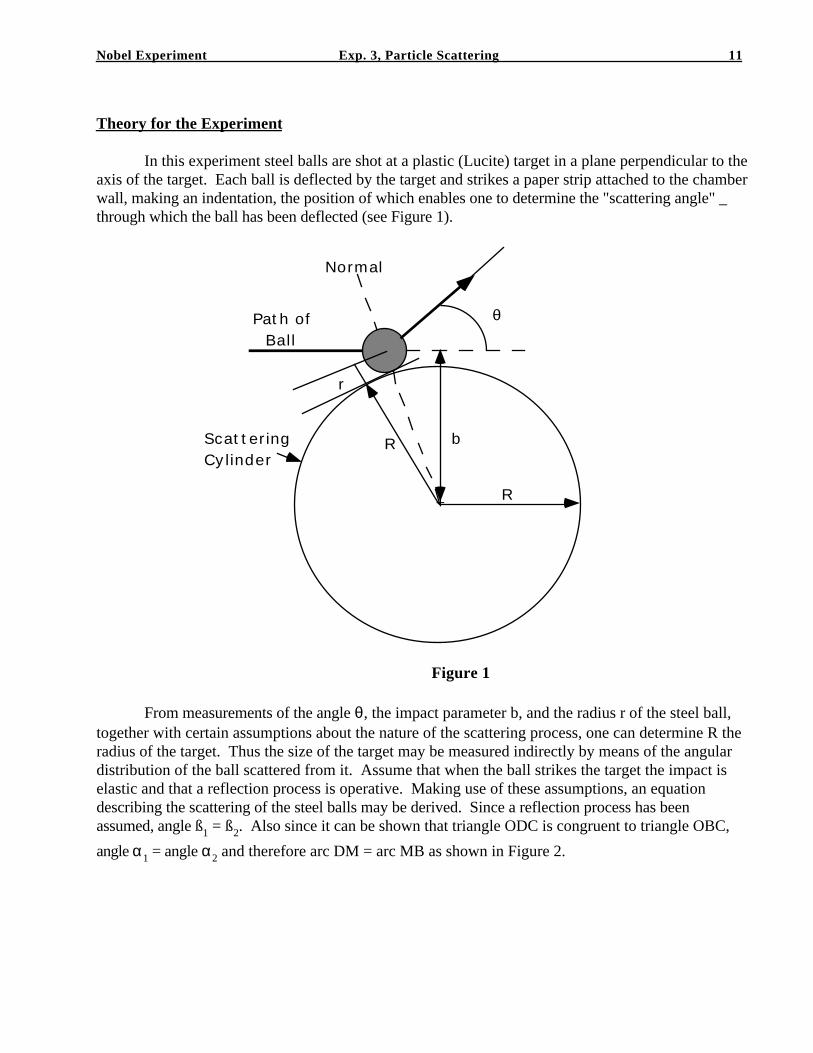
In this experiment steel balls are shot at a plastic (Lucite) target in a plane perpendicular to theaxis of the target. Each ball is deflected by the target and strikes a paper strip attached to the chamberwall, making an indentation, the position of which enables one to determine the "scattering angle" _through which the ball has been deflected (see Figure 1).
R+
θ
b
r
RScatteringCylinder
Path of Ball
Normal
Figure 1
From measurements of the angle θ, the impact parameter b, and the radius r of the steel ball,together with certain assumptions about the nature of the scattering process, one can determine R theradius of the target. Thus the size of the target may be measured indirectly by means of the angulardistribution of the ball scattered from it. Assume that when the ball strikes the target the impact iselastic and that a reflection process is operative. Making use of these assumptions, an equationdescribing the scattering of the steel balls may be derived. Since a reflection process has beenassumed, angle ß1 = ß2. Also since it can be shown that triangle ODC is congruent to triangle OBC,
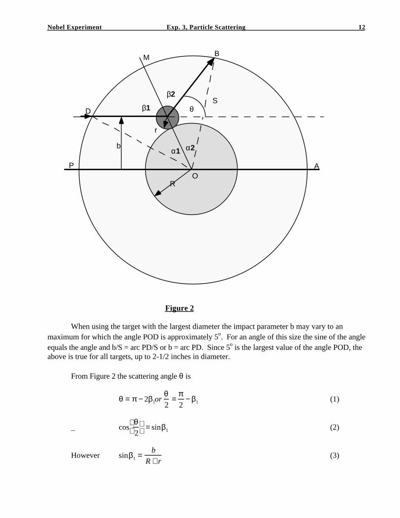
angle α1 = angle α2 and therefore arc DM = arc MB as shown in Figure 2.
Nobel Experiment Exp. 3, Particle Scattering 12
R
r
β1
β2
θ
bα1
O
D
P A
M B
S
α2
Figure 2
When using the target with the largest diameter the impact parameter b may vary to anmaximum for which the angle POD is approximately 5o. For an angle of this size the sine of the angleequals the angle and b/S = arc PD/S or b = arc PD. Since 5o is the largest value of the angle POD, theabove is true for all targets, up to 2-1/2 inches in diameter.
From Figure 2 the scattering angle θ is
θ = π − 2β1orθ2
=π2
− β1 (1)
_ cosθ2
= sinβ1 (2)
However sinβ1 =b
R + r(3)
Nobel Experiment Exp. 3, Particle Scattering 13
and cosθ2
=
b
R + r(4)
In this experiment θ cannot be measured directly but ß1 can be determined in terms of the arc AB, theimpact parameter, and the radius of the chamber wall.
Again from Figure 2 we have
ArcPM = πS − arcAB − b
2+ b
ArcPM =πS − arcAB + b
2
and ⋅ angle ⋅β1 =arcPM
S=
πS − arcAB + b
2s
These equations make it possible to calculate the scattering angle θ and the radius R of thetarget in terms of measurable quantities.
Apparatus
The apparatus consists of a cylindrical chamber (large flat plastic tub) mounted on a non-wrapping base. A horizontal slot in the chamber wall provides an opening for the bulb-operated airgun mounted on the base outside the chamber. The gun may be moved laterally by means of thescrew adjustment. The gun is used to project 0.181-inch steel balls at the cylindrical target in thecenter of the chamber. The target is polished Lucite, this material being better for this purpose thanhardened steel.
A roll of 2 inch wide paper tape, a roll of double-sided adhesive tape, a supply of 0.181-inchsteel balls, and two 5/32-inch diameter alignment rods are included.
Nobel Experiment Exp. 3, Particle Scattering 14
Procedure
SETTING UP THE APPARATUS. The scattering apparatus is shipped assembled and essentiallyready for use. The axis of the gun is made perpendicular to the axis of the screw in assembly. It isnecessary, however, to establish the zero position of gun and tape with reference to the center of thecylinder. By means of the double-sided adhesive tape attach a strip of wax-coated tape along thelower edge of the chamber wall on the side opposite the gun. Place the longer rod in the groove in thetarget and place the other in the barrel of the gun making one end almost touch the center post. Movethe gun until one rod is approximately over the other. Rotate the target, if necessary, until the rodsare exactly parallel. Now make final adjustment of the gun position to make the rods lie in the samevertical plane. The gun in this position is aimed directly at the center of the target and the impactparameter b is zero. The far end of the rod in the groove will locate the zero position of the tape fromwhich angles in either direction are measured.
The value of the impact parameter b that is a measure of the distance the gun is displaced fromits zero position, is determined by the pitch of the screw and the number of turns. The screw has 18threads per inch which, after converting to the metric system, means that the gun moves 0.141 cmper revolution of screw.
To load the gun rotate the metal sleeve until the hole in the sleeve lines up with the hole in the barrel,drop in the ball and rotate the sleeve to close the hold. The apparatus should be so leveled that thebarrel of the gun is horizontal; otherwise the ball may roll from the barrel before it can be fired. Bestresults are obtained when the hose of the aspirator is held straight and the balls are not fired too hard.
1. Attach a fresh strip of tape to the chamber wall using a length sufficient to cover aboutthree-fourths of the circumference, with waxed side out. Locate and mark zero position on the tape.Move the gun to the position for b = 0. In this position the ball should collide head-on with the targetand be deflected back to strike the wall directly beneath the gun.
2. The purpose of the experiment is to obtain data to check the validity of equation (4) anddetermine the value of R, the radius of the target. Fire the gun for a series of values of the impactparameter, firing several shots for each value, enabling cylinder, that is, use impact parameters on bothsides of the zero position. Be sure to correlate the impact parameter with the grouping of shotsobtained for that value. After each shot locate the dent made in the paper by the ball and label it sothat you can identify it later.
3. Remove the tape and measure the distance from the zero position on the tape to eachindentation. Average these values for each group. Record these as values of the arc AB againstcorresponding values of the impact parameter b.
4. Using equation (6) calculate values of the angles ß1 for corresponding values of the arc AB.
Now using equation (1) calculate corresponding values of θ/2. Plot cos θ/2 against b and determineR + r. Compare this value with that obtained by direct measurement.
The extent to which equation (4) describes our data provides us with an indication of thevalidity of our assumptions.
Nobel Experiment Exp. 3, Particle Scattering 15
HARD-SPHERE MODEL OF ATOMIC CATTERING
DIFFERENTIAL CROSS SECTION IN 2-D
LABORATORY EXPERIMENT
Introduction
In the previous experiment the scattering apparatus was used to determine the diameter of thetarget from the scatter pattern of projectiles deflected from the target and the known impactparameter. In the real physical scattering experiment it is impossible to know the impact parameterof the incoming particle. Research in nuclear physics measure the number of scattered particles at aknown angle and from this data they can calculate the differential cross section of the scatteringnucleus. In this experiment, the exact conditions of an experiment in nuclear physics will be simulatedas close as possible. The impact parameter will not be measured as this is not possible in any realatomic scattering experiment.
Theory
Differential Cross SectionIn the real nuclear scattering experiment it is impossible to know the impact parameter of the
incoming particles. A particle detector is placed opposite the scattering material at known angles andthe number of scattered projectile particles are detected. This detector has an angular width ∆θ, so itactually counts the particles that enter through the conical wedge bounded by θ and θ + ∆θ. Theseparticles have come from the beams whose impact parameters lie between b and b - ∆b as shown inFigure 1.
Nobel Experiment Exp. 3, Particle Scattering 16
b
δσ=2πbδb
δb ScatteringCenter
δθ
δN(θ)
Detecting Plane
IncomingParticles
Scattering Angle θ
Figure 1
The washer-like area ∆σ = 2πb . ∆b is called the scattering cross-section, and is related to ∆N, thenumber of particles scattered into the angle θ and θ + ∆θ, by
∆N(θ) = I •∆σ = I • 2πb •∆ b (1)
where I is the particle flux, the number of particles per unit area normal to the beam per second.
The differential scattering cross-section is
∆σ∆Ω
=1
I
∆N(θ )
∆Ω=
b
sin θ•
∆b
∆θ(2)
where ∆Ω is the solid angle, defined as the
(area / r2) = 2πsinθ∆θ. (3)
Nobel Experiment Exp. 3, Particle Scattering 17
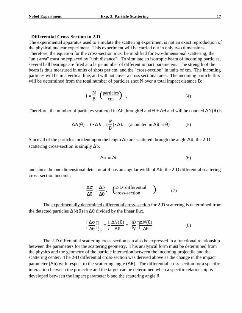
Differential Cross Section in 2-DThe experimental apparatus used to simulate the scattering experiment is not an exact reproduction ofthe physical nuclear experiment. This experiment will be carried out in only two dimensions.Therefore, the equation for the cross-section must be modified for two-dimensional scattering; the"unit area" must be replaced by "unit distance". To simulate an isotropic beam of incoming particles,several ball bearings are fired at a large number of different impact parameters. The strength of thebeam is thus measured in units of shots per cm, and the "cross-section" in units of cm. The incomingparticles will be in a vertical line, and will not cover a cross sectional area. The incoming particle flux Iwill be determined from the total number of particles shot N over a total impact distance B;
I = NB (particles
cm ) . (4)
Therefore, the number of particles scattered in ∆b through θ and θ + ∆θ and will be counted ∆N(θ) is
∆N(θ) = I •∆ b = (N
B)•∆ b (#counted in ∆θ at θ) (5)
Since all of the particles incident upon the length ∆b are scattered through the angle ∆θ, the 2-Dscattering cross-section is simply ∆b;
∆σ ≡ ∆b (6)
and since the one dimensional detector at θ has an angular width of ∆θ, the 2-D differential scatteringcross-section becomes
∆σ∆θ
=∆b
∆θ. (2-D differential
cross-section ) (7)
The experimentally determined differential cross-section for 2-D scattering is determined fromthe detected particles ∆N(θ) in ∆θ divided by the linear flux,
∆σ∆θ
exp
=1
I
∆N(θ)
∆θ=
B
N
∆N(θ)
∆θ(8)
The 2-D differential scattering cross-section can also be expressed in a functional relationshipbetween the parameters for the scattering geometry. This analytical form must be determined fromthe physics and the geometry of the particle interaction between the incoming projectile and thescattering center. The 2-D differential cross-section was derived above as the change in the impactparameter (∆b) with respect to the scattering angle (∆θ). The differential cross-section for a specificinteraction between the projectile and the target can be determined when a specific relationship isdeveloped between the impact parameter b and the scattering angle θ.
Nobel Experiment Exp. 3, Particle Scattering 18
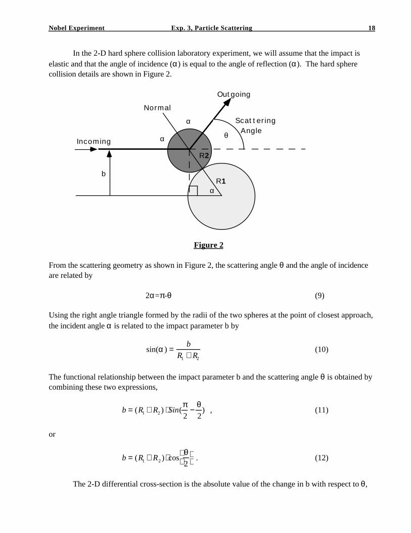
In the 2-D hard sphere collision laboratory experiment, we will assume that the impact iselastic and that the angle of incidence (α) is equal to the angle of reflection (α). The hard spherecollision details are shown in Figure 2.
θ
b
Incoming
Normal
Outgoing
Scattering Angle
α
α
R1
R2
α
Figure 2
From the scattering geometry as shown in Figure 2, the scattering angle θ and the angle of incidenceare related by
2α=π-θ (9)
Using the right angle triangle formed by the radii of the two spheres at the point of closest approach,the incident angle α is related to the impact parameter b by
sin(α ) =b
R1 + R2
(10)
The functional relationship between the impact parameter b and the scattering angle θ is obtained bycombining these two expressions,
b = (R1 + R2 ) ⋅ Sin(π2
−θ2
) , (11)
or
b = (R1 + R2 ) ⋅ cosθ2
. (12)
The 2-D differential cross-section is the absolute value of the change in b with respect to θ,
Nobel Experiment Exp. 3, Particle Scattering 19
∆σ∆θ
=∆b
∆θ=
1
2(R1 + R2 ) • sin
θ2
, (13)
The 2-D differential cross-section is expressed in a theoretical form; Equation (13) andin a experimental form; Equation (8). A comparison of the values obtained from Equations (8)and (13) furnishes a means of checking experiment against theory.
Scattering Angle
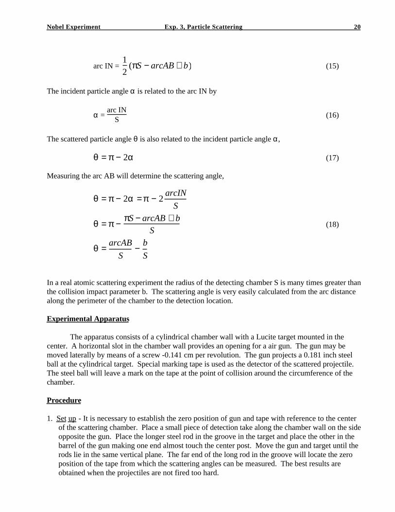
The evaluation of the scattering angle from measurements made around the perimeter of thedetection chamber must be considered in more detail. Figure 3 shows the geometry of the detectionchamber. The particles are incident at point I and strike the target at the center of the chamber and arethen scattered to the point B on the perimeter. As shown in Figure 3, the incident particle angle isrelated to the arc IN when measured from the center of the scattering chamber.
θ
b
Incoming
Normal
Outgoing
Scattering Angle
α
α
R1
R2
α
S
N
B
I
A
Figure 3
If we take two times the arc IN and add the arc AB, this will be equal to one-half the circumferenceplus an extra impact distance b. (b ≈ arc b)
2 . arc IN + arc AB = πS + b (14)
Solving for the arc IN
Nobel Experiment Exp. 3, Particle Scattering 20
arc IN = 12
(πS − arcAB + b) (15)
The incident particle angle α is related to the arc IN by
α = arc IN
S (16)
The scattered particle angle θ is also related to the incident particle angle α,
θ = π − 2α (17)
Measuring the arc AB will determine the scattering angle,
θ = π − 2α = π − 2arcIN
S
θ = π − πS − arcAB + bS
θ = arcAB
S− b
S
(18)
In a real atomic scattering experiment the radius of the detecting chamber S is many times greater thanthe collision impact parameter b. The scattering angle is very easily calculated from the arc distancealong the perimeter of the chamber to the detection location.
Experimental Apparatus
The apparatus consists of a cylindrical chamber wall with a Lucite target mounted in thecenter. A horizontal slot in the chamber wall provides an opening for a air gun. The gun may bemoved laterally by means of a screw -0.141 cm per revolution. The gun projects a 0.181 inch steelball at the cylindrical target. Special marking tape is used as the detector of the scattered projectile.The steel ball will leave a mark on the tape at the point of collision around the circumference of thechamber.
Procedure
1. Set up - It is necessary to establish the zero position of gun and tape with reference to the centerof the scattering chamber. Place a small piece of detection take along the chamber wall on the sideopposite the gun. Place the longer steel rod in the groove in the target and place the other in thebarrel of the gun making one end almost touch the center post. Move the gun and target until therods lie in the same vertical plane. The far end of the long rod in the groove will locate the zeroposition of the tape from which the scattering angles can be measured. The best results areobtained when the projectiles are not fired too hard.
Nobel Experiment Exp. 3, Particle Scattering 21
2. Attach a fresh strip of marking tape around the entire circumference of the chamber with the whiteside out. Locate and mark the zero position on the tape. Measure the radius of the scatteringchamber (S).
3. To simulate an isotropic beam of incoming particles, several ball bearings are fired at a large numberof different impact parameters. The impact parameters are chosen so that the width of the beamis greater than the scatterer and to ensure isotropy, the same number of ball must be fired fromeach position of the sun and the gun is traversed the same distance before each firing. Startingwith the gun in the zero position, fire about four balls at each position with one-quarter turn ofthe gun-traversing screw between positions.
4. Remove the tape and determine the number of scattered particles ∆N(θ) within ∆θ at θ. Dividethe circumference into equal increments of 10 or 20 degrees and count the number of marks withinthese increments.
5. The differential cross section is determined by counting the number of marks as a function or lineardistance along the paper. The scattered angle is determined using the method discussed in thetheory section.
6. Make a histogram plot of the number of scattered particles verses the angle of scatter. Compare tothe theoretical prediction that the number of scattered particles should show a sin(θ/2)relationship.
7. Determine the total "cross-section" both experimentally and theoretically and compare theresults.