Developed by: JACOBS for Air Force Civil Engineering Center (AFCEC) Ralph “Rick” Sinkfield, DAF – Project Manager Email: [email protected]BIM Manual V1.0 Facilities Dynamic Prototypes Military Working Dog Kennel BIM Design March 28, 2013
Specification 4: Acoustical Baffle Panel System ....................................................... 28-32
3
INTRODUCTION
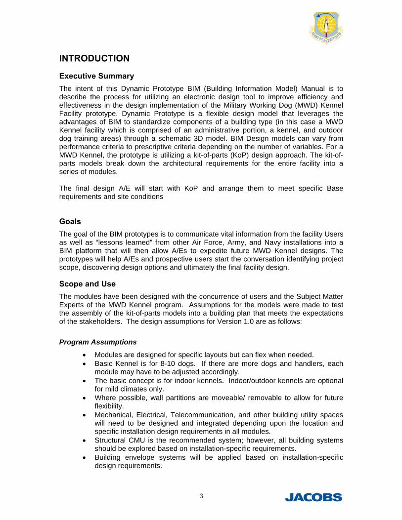
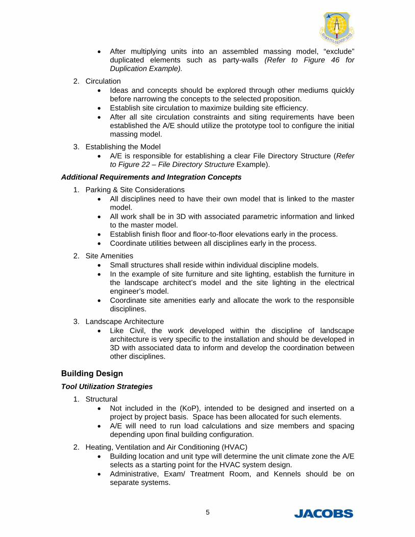
Executive Summary The intent of this Dynamic Prototype BIM (Building Information Model) Manual is to describe the process for utilizing an electronic design tool to improve efficiency and effectiveness in the design implementation of the Military Working Dog (MWD) Kennel Facility prototype. Dynamic Prototype is a flexible design model that leverages the advantages of BIM to standardize components of a building type (in this case a MWD Kennel facility which is comprised of an administrative portion, a kennel, and outdoor dog training areas) through a schematic 3D model. BIM Design models can vary from performance criteria to prescriptive criteria depending on the number of variables. For a MWD Kennel, the prototype is utilizing a kit-of-parts (KoP) design approach. The kit-of-parts models break down the architectural requirements for the entire facility into a series of modules. The final design A/E will start with KoP and arrange them to meet specific Base requirements and site conditions
Goals The goal of the BIM prototypes is to communicate vital information from the facility Users as well as “lessons learned” from other Air Force, Army, and Navy installations into a BIM platform that will then allow A/Es to expedite future MWD Kennel designs. The prototypes will help A/Es and prospective users start the conversation identifying project scope, discovering design options and ultimately the final facility design.
Scope and Use The modules have been designed with the concurrence of users and the Subject Matter Experts of the MWD Kennel program. Assumptions for the models were made to test the assembly of the kit-of-parts models into a building plan that meets the expectations of the stakeholders. The design assumptions for Version 1.0 are as follows:
Program Assumptions
Modules are designed for specific layouts but can flex when needed. Basic Kennel is for 8-10 dogs. If there are more dogs and handlers, each
module may have to be adjusted accordingly. The basic concept is for indoor kennels. Indoor/outdoor kennels are optional
for mild climates only. Where possible, wall partitions are moveable/ removable to allow for future
flexibility. Mechanical, Electrical, Telecommunication, and other building utility spaces
will need to be designed and integrated depending upon the location and specific installation design requirements in all modules.
Structural CMU is the recommended system; however, all building systems should be explored based on installation-specific requirements.
Building envelope systems will be applied based on installation-specific design requirements.
4
Windows should be included in the modules based on configuration layouts and site requirements.
Outdoor circulation, parking, MWD training areas, and storage areas will adapt to specific site and installation requirements.
All site and building layouts must incorporate one way MWD travel. Certain modules and program components are optional and will be the
decision of the individual bases. Any reconfigurations of the units must meet the requirements of the specific
Base user.
Kit of Parts (KoP)
1. Architectural
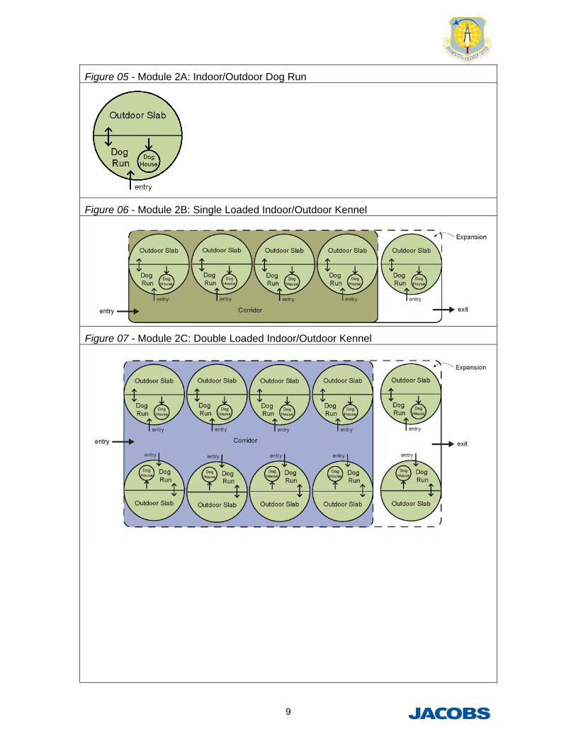
a. Kit of Parts include: Module 1A: Indoor Dog Run Module 1B: Single Loaded Indoor Kennel Module 1C: Double Loaded Indoor Kennel Module 2A: Indoor/Outdoor Dog Run Module 2B: Single Loaded Indoor/Outdoor Kennel Module 2C: Double Loaded Indoor/Outdoor Kennel Module 3: Administrative Module 4: Exam/Treatment Room Module 5: Food Prep/Daily Storage Module 6: Tack Room Module 7: Food Storage Module 8: Restrooms/Locker Rooms Module 9: Mechanical Room Module 10: Optional Exterior Storage Module 11: Exterior Obedience Course Module 12: Optional Outdoor Exercise Area Module 13: Outdoor MWD Break Area Module 14: Optional Bleachers Module 15: Optional Portable Explosives Storage Module 16: Optional Isolation Dog Run Module 17A – 17Q: Obstacles for Obedience Course
b. It is intended that all non-optional modules be utilized to configure a site adapt building floor plan as needed (Refer to Building Plan Examples).
GUIDELINE INTEGRATION
Site Design Tool Utilization Strategies
1. Siting Requirements Utilize the kit-of-parts to assemble the initial massing model. Group units before multiplying the units to take advantage of BIM. Configure model to the appropriate site dimensions and established
setback requirements.
5
After multiplying units into an assembled massing model, “exclude” duplicated elements such as party-walls (Refer to Figure 46 for Duplication Example).
2. Circulation Ideas and concepts should be explored through other mediums quickly
before narrowing the concepts to the selected proposition. Establish site circulation to maximize building site efficiency. After all site circulation constraints and siting requirements have been
established the A/E should utilize the prototype tool to configure the initial massing model.
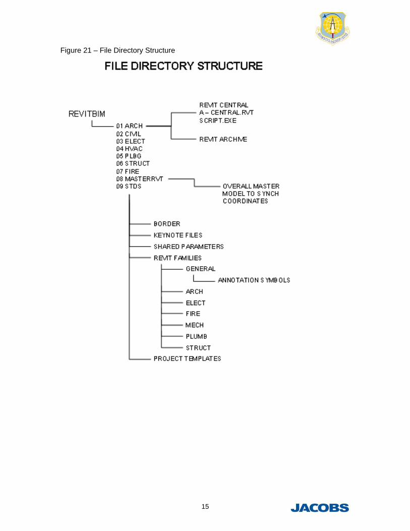
3. Establishing the Model A/E is responsible for establishing a clear File Directory Structure (Refer
to Figure 22 – File Directory Structure Example).
Additional Requirements and Integration Concepts
1. Parking & Site Considerations All disciplines need to have their own model that is linked to the master
model. All work shall be in 3D with associated parametric information and linked
to the master model. Establish finish floor and floor-to-floor elevations early in the process. Coordinate utilities between all disciplines early in the process.
2. Site Amenities Small structures shall reside within individual discipline models. In the example of site furniture and site lighting, establish the furniture in
the landscape architect’s model and the site lighting in the electrical engineer’s model.
Coordinate site amenities early and allocate the work to the responsible disciplines.
3. Landscape Architecture Like Civil, the work developed within the discipline of landscape
architecture is very specific to the installation and should be developed in 3D with associated data to inform and develop the coordination between other disciplines.
Building Design Tool Utilization Strategies
1. Structural Not included in the (KoP), intended to be designed and inserted on a
project by project basis. Space has been allocated for such elements. A/E will need to run load calculations and size members and spacing
depending upon final building configuration.
2. Heating, Ventilation and Air Conditioning (HVAC) Building location and unit type will determine the unit climate zone the A/E
selects as a starting point for the HVAC system design. Administrative, Exam/ Treatment Room, and Kennels should be on
separate systems.
6
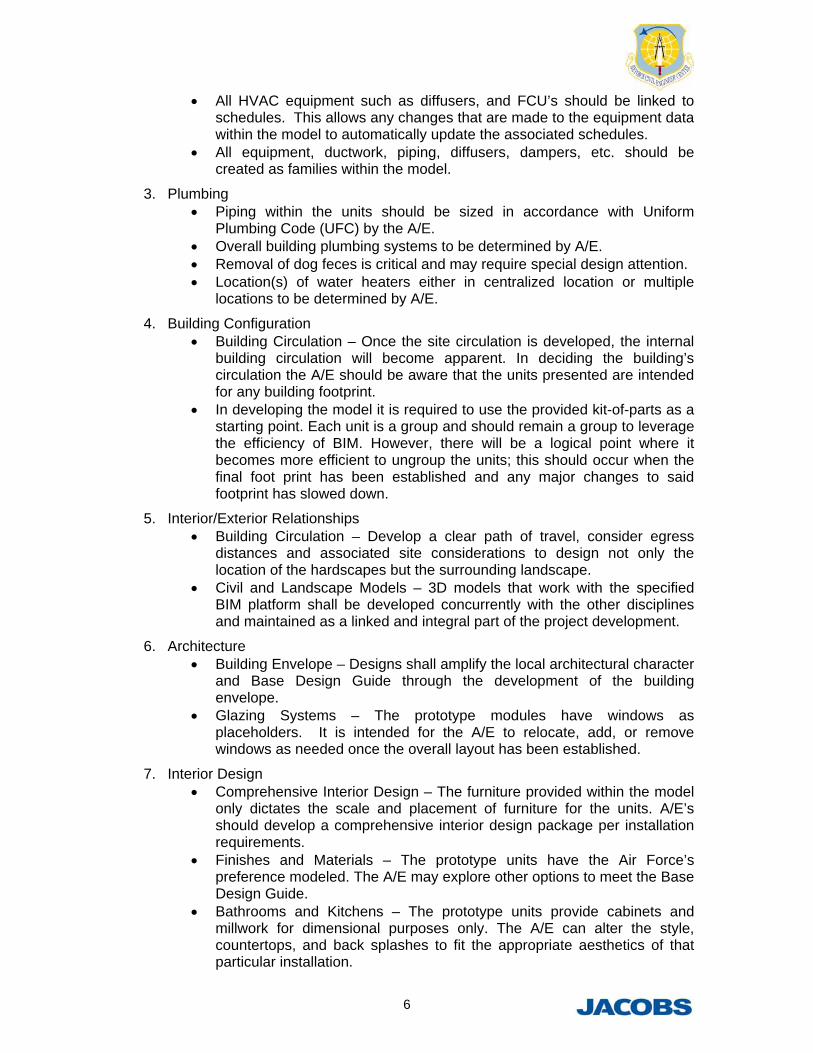
All HVAC equipment such as diffusers, and FCU’s should be linked to schedules. This allows any changes that are made to the equipment data within the model to automatically update the associated schedules.
All equipment, ductwork, piping, diffusers, dampers, etc. should be created as families within the model.
3. Plumbing Piping within the units should be sized in accordance with Uniform
Plumbing Code (UFC) by the A/E. Overall building plumbing systems to be determined by A/E. Removal of dog feces is critical and may require special design attention. Location(s) of water heaters either in centralized location or multiple
locations to be determined by A/E.
4. Building Configuration Building Circulation – Once the site circulation is developed, the internal
building circulation will become apparent. In deciding the building’s circulation the A/E should be aware that the units presented are intended for any building footprint.
In developing the model it is required to use the provided kit-of-parts as a starting point. Each unit is a group and should remain a group to leverage the efficiency of BIM. However, there will be a logical point where it becomes more efficient to ungroup the units; this should occur when the final foot print has been established and any major changes to said footprint has slowed down.
5. Interior/Exterior Relationships Building Circulation – Develop a clear path of travel, consider egress
distances and associated site considerations to design not only the location of the hardscapes but the surrounding landscape.
Civil and Landscape Models – 3D models that work with the specified BIM platform shall be developed concurrently with the other disciplines and maintained as a linked and integral part of the project development.
6. Architecture Building Envelope – Designs shall amplify the local architectural character
and Base Design Guide through the development of the building envelope.
Glazing Systems – The prototype modules have windows as placeholders. It is intended for the A/E to relocate, add, or remove windows as needed once the overall layout has been established.
7. Interior Design Comprehensive Interior Design – The furniture provided within the model
only dictates the scale and placement of furniture for the units. A/E’s should develop a comprehensive interior design package per installation requirements.
Finishes and Materials – The prototype units have the Air Force’s preference modeled. The A/E may explore other options to meet the Base Design Guide.
Bathrooms and Kitchens – The prototype units provide cabinets and millwork for dimensional purposes only. The A/E can alter the style, countertops, and back splashes to fit the appropriate aesthetics of that particular installation.
7
8. Electrical Exterior lighting and other associated work with the buildings exterior or
landscape will be developed as part of the local installation design. Building electrical loads and service to be determined by A/E.
9. Fire Protection The administrative and kennel areas are not required to be protected by a
fire sprinkler system per UFC 3-600-01, part 4-2.2. Provide a complete automatic Fire Alarm system per NFPA72.
Software Requirements Additional Requirements
1. Autodesk Revit 2013 or higher (latest Service Pack) Revit was utilized in developing the Prototypes and shall be utilized in
Figure 18 – Building A: Single-Loaded Indoor Kennel, Separate Buildings
13
Figure 19 – Building B: Double-Loaded Indoor/Outdoor Kennel, Single Building
14
Figure 20 – Building B.1: Double-Loaded Indoor/Outdoor Kennel with Optional Isolation Dog Run
15
Figure 21 – File Directory Structure
16
Figure 22 – Duplication Example
Figure 23 – Group Manipulation Example
17
APPENDIX Specifications are included as guidance for future A/E’s and Bases during the planning and design process. Final equipment specifications must comply with specific Base requirements.
Specification 1: Ceiling-Mounted Exam Light
Harmony® LA300 Examination Lighting System (or approved equal) Lighting designed for patient and caregiver with low profile, high quality illumination for critical care and labor and delivery settings
The Harmony LA300 Examination Lighting System is designed specifically for minor procedures in an ICU or ER. The LA300 provides high-intensity, color-corrected lighting and its compact mobile, ceiling- or wall-mount options can be installed anywhere procedure lighting is necessary. Small and extremely maneuverable Cool, color-corrected light Intensity level is adjustable from the bezel 24,000 to 60,000 lux CRI of 94 Color temperature of 4400K
Intensity 24,000 to 60,000 lux
Pattern size 9" (229 mm)
Depth of field 34 - 59"
Focal range 34 - 59"
Color temperature 4400K
CRI (Color Rendering Index) 94
Mobile base size 22¼" x 22" (565 mm x 558 mm)
Mobile base height, weight 69" (1732 mm), 76 lb.(35 kg)
Horizontal extension arm 31½" (800 mm)
Spring arm 40" (1016 mm)
18
Specification 2: Stainless Steel Rolling Cage (Mobile Transport Unit)
Mobile Transport Unit
Weight: 119 lbs
Mobility and design allow this unit to be used for receiving and releasing patients, moving them, as a temporary holding kennel, or even as an emergency exam and treatment table.
Built like the Shor-Line modular cages, the mobile transport unit is insulated and finished with polished stainless steel side and top panels.
The universal door is designed for right-hand or left-hand opening. Large 5" heavy-duty corrosion resistant casters let you maneuver the unit easily through
most door openings. All casters feature locking mechanisms to hold the unit stationary when not in use. Full width bar handle for easy control.
19
Specification 3: Table Tub
C lass ic 18 Prep-Procedure Table
Features an 18 single-depth tub designed for all procedures, plus tub depth permits dipping.
ALPRO ® ACOUSTICAL SYSTEMS CEILING PANEL SYSTEMS (or approved equal)
Note to Specifier: ALPRO® Systems are a finished decorative/functional product and should be specified per The Construction Specifications Institute’s format in the following Divisions. All Division numbers listed within this document refer to the CSI format: 09 5100 - Acoustical Ceilings, 09 5400 - Specialty Ceilings, or 09 8000 - Acoustical Treatments
PART 1 – GENERAL
1.1 RELATED DOCUMENTS
A. Drawings and General Provisions of the Contract, including General and Supplementary Conditions and Division 1 Specification Sections apply to this Section.
1.2 SUMMARY
A. This section includes Metal Ceiling Panels as shown on the architectural drawings.
B. Related Sections include the Following: (list applicable sections)
1.3 SUBMITTALS
A. Manufacturer’s Literature and Data:
1. Product Data: Submit manufacturer’s technical data and brochures specified system.
B. Shop Drawings:
1. Shop drawings shall show dimensions, sizes, thickness, finishes, joining, mounting attachments, and relationship to adjoining work.
C. Samples:
1. Samples shall include a minimum 12” X 12” nominal piece of each type of metal, finished as specified, and accessories.
D. Certification:
1. Submit certification from manufacturer of ceiling panels attesting that products comply with specified requirements including finish as specified.
E. Qualification Data:
1. Firms specified in “Quality Assurance” Article must demonstrate their capabilities and experience by including lists of completed projects with project names and addresses, names and addresses of architects and owners, and other information specified.
F. Product Test Reports: 1. All products furnished shall have a flame spread classification of 0-25 for a Class A or Class 1
rating in accordance with ASTM E84.
2. All products furnished shall be tested in accordance with ASTM C-423-90 for Sound Absorption. Test results for a Type E-400 ceiling mounting method shall yield an NRC (Noise Reduction Coefficient) of no less than 1.0.
21
G. Maintenance Data: 1. Provide maintenance instructions for acoustical panels to be included in maintenance manuals as specified in Division 1. H. Warranty:
1. Provide product warranty for one year from date of substantial project completion.
1.4 QUALITY ASSURANCE
A. Manufacturer: Firm with manufacturing and delivery capacity required for the project, shall have successfully completed at least ten projects within the past five years, utilizing systems, materials and techniques as herein specified.
B. Fabricator must own and operate its own Manufacturing facilities for all metal components. Systems consisting of components from a variety of manufacturers will not be considered or accepted.
C. Manufacturer/Fabricator must own and operate its own Painting and Finishing facility to assure single source responsibility and quality control.
D. Testing Agency Qualifications: An independent testing agency, acceptable to authorities having jurisdiction, with the experience and capability to conduct testing indicated, as documented according to ASTM E 548.
1.5 DELIVERY, STORAGE & HANDLING
A. All materials shall be protected during fabrication, shipment, site storage and erection to prevent damage to the finished work from other trades. Store acoustical panels inside a well-ventilated area, away from uncured concrete and masonry, and protected from the weather, moisture, soiling, abrasion, extreme temperatures, and humidity.
PART 2 – PRODUCTS
2.1 MANUFACTURER
A. ALPRO® Systems shall be manufactured by ALPRO® Acoustical Systems, Division of Gordon, Inc., 5023 Hazel Jones Road, Bossier City, LA 71111, (888) 733-3836, FAX (800) 877-8746, www.alproacoustics.com, [email protected].
B. The listed manufacturer shall not be construed as closing specifications to other prospective manufacturers, but rather as establishing a level of quality in a metal system. Other systems may be submitted for approval; as provided for in the specifications at least 10 working days prior to submission of bids. Companies desiring to submit a proposal shall submit all descriptive information of the system proposed including photographs and shop drawings of at least three projects similar in detail and scope.
2.2 SYSTEM DESCRIPTION
A. Ceiling System shall be ALPRO® Acoustical Systems. All panels, perimeter trims and suspension components including acoustical component shall be provided as a complete package of this work.
22
2.3 MATERIALS
A. Suspension System
1. Extruded aluminum as manufactured by ALPRO® , Division of Gordon, Inc. shall consist of main tees, cross tees, perimeter angle, perimeter trim, and any necessary clips and splices required for a complete system as required to meet local building codes.
2. Deflection of grid shall be limited to L/360 of the span when full dead load is applied. (ASTM C 635)
3. Aluminum Extrusions shall be 6063-T6 alloy. (ASTM B 221, ASTM B 221 M)
4 General: Provide metals free from surface blemishes where exposed to view in finished unit. Surfaces that exhibit pitting, seam marks, roller marks, stains, and discolorations, or other imperfections on finished units are not acceptable. All metal shall be of the highest grade -commercial type,
B. Metal Panels
1. Choose from the following selections for exposed metal. Aluminum sheet shall be 3003-H14 alloy, minimum .020”, 032” recommended, (ASTM B 209). Galvanized steel sheet (ASTM A366/A 366M) shall be minimum of .0216” (26 Gauge), .0276” (24 gauge) recommended.
2. The metal acoustical Ceiling Panels shall be corrugated using (Specified ALPRO® Pattern Type) and perforated with 1/8” diameter holes on 21/64” staggered centers, approximately 13% open area.
3. The panels shall be fabricated of stucco-embossed or smooth aluminum (.020” or .032”) OR smooth galvanized (22, 24, 26) gauge steel.
4. Sound Absorption Material: a. Provide fiberglass (1.5” or 2” or other thickness) X (1.5 #, 2 #, or other density). The
fiberglass panel shall be wrapped in Class A, per ASTM E84, (Clear Polyvinylchloride) (Black Polyethylene).
2.4 FINISHES
A. Powder Coat Finish – (Interior use only)
1. All ALPRO® Panels & Accessories shall receive a micro-etched pretreatment prior to receiving an electrostatically applied powder coat paint finish.
2. All cut edges, including perforated holes must be coated. Finish shall be cured and oven baked to insure paint adhesion and uniform surface hardness.
3. Paint Color to be selected from ALPRO® Standard Colors (or approved custom color).
OR
A. Alternative Finishes – (exterior or interior use) 1. Aluminum shall receive a factory applied and baked finish of a 70% Kynar®® or Hylar 5000®
(Fluropon® or Fluropon Classic® II) paint or a 50% Kynar® or Hylar 5000® (Acrodize™ Hardcoat or Acroflur™) paint
23
2. All cut edges, including perforated holes must be coated. Finish shall be cured and oven baked to insure paint adhesion and uniform surface hardness.
3. Material that is to be field painted should be degreased and primed per paint manufacturer’s specifications.
4. Galvanized Steel sheets shall receive a factory applied and baked finish of Fluropon®® paint. Galvanized Steel is recommended for interior use only.
PART 3 –EXECUTION
3.1 INSPECTION
B. Examine building structure scheduled to receive ceiling system for unevenness or irregularities that would affect quality and execution of work.
C. Tolerances:
1. Install ceiling system with maximum permissible deflection of L/360 of span maximum surface deviation of 1/8” in 4’-0” (No load applied) ASTM 635-92.
3.2 INSTALLATION
A. General: Comply with manufacturer’s printed instructions, governing regulations for Seismic Codes, and with the Ceiling & Interior Systems Construction Association standards applicable to work.
B. Space Enclosure: Do not install any work until space is enclosed and weatherproofed, wet-work in space is completed and nominally dry, work above ceilings is complete, and temperature and humidity is continuously maintained at values near those of final occupancy.
3.3 CLEANING
A. Clean all surfaces following installation.
B. Replace material having scratches, abrasions, or other defects, with unblemished panels, or suspension.
C. Maintenance per manufacturer’s finish maintenance instructions.
3.4 PROTECTION
A. Protection of ALPRO® Acoustical Systems from damage by other trades after installation to be provided by general contractor.
3.5 GENERAL RESPONSIBILITY
A. Variation from specification: Any variation from this specification resulting in additional cost to any other contractor or subcontractor on this project shall be the sole financial responsibility of the contractor for the work of this section.
24
ALP
RO
PE
RIM
ET
ER
TR
IM PE
RIM
ET
ER
SP
LIC
E C
LIP
TY
PC
RO
SS
TE
E T
YP
MA
INT
EE
TY
P
MA
IN T
EE
SP
LIC
EC
LIP
FA
CT
OR
Y P
AIN
TE
DP
AN
EL
SC
RE
W T
YP
TC
2 C
LIP
WIT
HF
AS
TE
NE
R T
YP
ALP
RO
C-P
AN
EL
1WA
Y C
LIP
2WA
YC
LIP T
ITLE
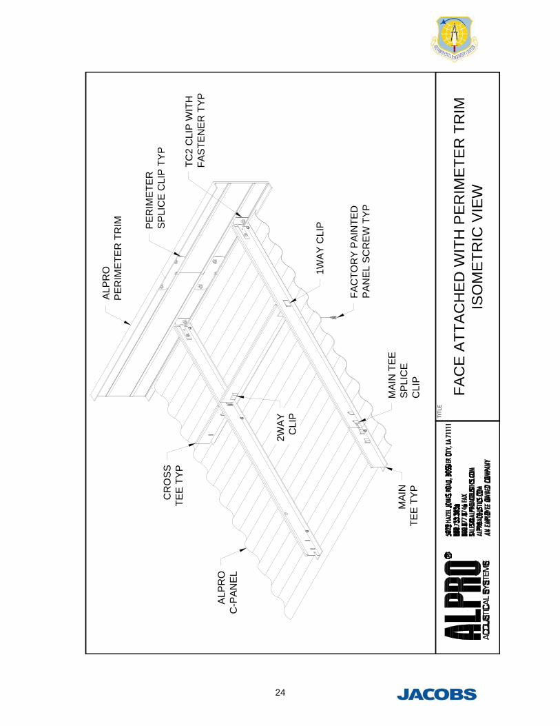
FA
CE
AT
TA
CH
ED
WIT
H P
ER
IME
TE
R T
RIM
ISO
ME
TR
IC V
IEW
25
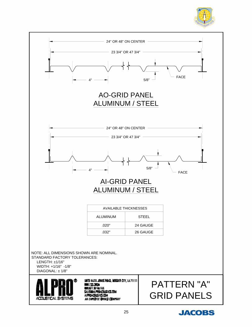
NOTE: ALL DIMENSIONS SHOWN ARE NOMINAL.STANDARD FACTORY TOLERANCES: LENGTH: ±1/16" WIDTH: +1/16" -1/8" DIAGONAL: ± 1/8"
AO-GRID PANELALUMINUM / STEEL
AI-GRID PANELALUMINUM / STEEL
AVAILABLE THICKNESSES
ALUMINUM STEEL
.020" 24 GAUGE
.032" 26 GAUGE
5/8"FACE
4"
23 3/4" OR 47 3/4"
23 3/4" OR 47 3/4"
4" 5/8"FACE
24" OR 48" ON CENTER
24" OR 48" ON CENTER
PATTERN "A"GRID PANELS
26
NOTE: ALL DIMENSIONS BASED ON.032" STUCCO EMBOSSEDALUMINUM PERFORATED PANELS.DIMENSIONS ARE NOMINAL ANDWILL VARY WITH DIFFERENTTHICKNESSES AND TYPES OF MATERIAL.STANDARD FACTORY TOLERANCES: LENGTH: ± 5/32" WIDTH: ± 3/16" DIAGONAL: ± 3/16"
ALUMINUM / STEELMAXIMUM LENGTH: 120"
ALUMINUM / STEELMAXIMUM LENGTH: 120"
AVAILABLE MATERIAL
ALUMINUM STEEL
.032" 22 GAUGE
.020" 24 GAUGE
26 GAUGE
FACE
1/2"2 1/2"
LAPPED WIDTH
PANEL WIDTH
1/2"
FACE
LAPPED WIDTH
PANEL WIDTH
2 1/2"
NOMINAL DIMENSIONS
LAPPED WIDTH PANEL WIDTH
54 3/4" 55 3/4"
NOMINAL DIMENSIONS
LAPPED WIDTH PANEL WIDTH
42 3/4" 44 3/4"
PATTERN "B"PANELS
27
NOTE: ALL DIMENSIONS BASED ON.032" STUCCO EMBOSSEDALUMINUM PERFORATED PANELS.DIMENSIONS ARE NOMINAL ANDWILL VARY WITH DIFFERENTTHICKNESSES AND TYPES OF MATERIAL.STANDARD FACTORY TOLERANCES: LENGTH: ± 5/32" WIDTH: ± 3/16" DIAGONAL: ± 3/16"
AVAILABLE MATERIAL
ALUMINUM STEEL
.032" 22 GAUGE
.020" 24 GAUGE
26 GAUGE
5/8"2 23/32"
NOMINAL
FACE
LAPPED WIDTH
PANEL WIDTH
ALUMINUM
STEEL
NOMINAL DIMENSIONS
LAPPED WIDTH PANEL WIDTH PANEL LENGTH
40 7/8" 42 1/2"144" MAX FOR ALL
AVAILABLE MATERIALS
51 5/8" 52 3/4" 120" MAX FOR 26GA STEEL
NOMINAL DIMENSIONS
LAPPED WIDTH PANEL WIDTH PANEL LENGTH
40 3/8" 42"144" MAX FOR ALL
AVAILABLE MATERIALS
51 5/8" 52 3/4"120" MAX FOR .020"
ALUMINUM
NOMINAL
PATTERN "C"PANELS
28
ALPRO® Guideline Specifications
ALPRO ® ACOUSTICAL SYSTEMS BAFFLE PANEL SYSTEM (or approved equal)
Note to Specifier: ALPRO® Systems are a finished decorative/functional product and should be specified in: 09 5100 - Acoustical Ceilings, 09 5400 - Metal Ceiling, 09 5100 - Acoustical Ceilings, Baffles & Screens or 09 8400 - Acoustical Treatments
PART 1 – GENERAL
1.1 RELATED DOCUMENTS
A. Drawings and General Provisions of the Contract, including General and Supplementary Conditions and Division 1 Specification Sections apply to this Section.
1.2 SUMMARY
A. This section includes Metal Baffle Panel systems as shown on the architectural drawings.
B. Related Sections include the Following: (list applicable sections)
1.3 SUBMITTALS
A. Manufacturer’s Literature and Data:
1. Product Data: Submit manufacturer’s technical data and brochures for each type of specified system required.
B. Shop Drawings:
1. Shop drawings shall show dimensions, sizes, thickness, finishes, joining, mounting attachments, and relationship of adjoining work.
C. Samples:
1. Samples shall include a minimum 12” X 12” nominal piece of each type of metal, finished as specified, and accessories.
D. Certification:
1. Submit certification from manufacturer of acoustical baffle panels attesting that products comply with specified requirements including finish as specified.
E. Qualification Data:
1. Firms specified in “Quality Assurance” Article must demonstrate their capabilities and experience by including lists of completed projects with project names and addresses, names and addresses of architects and owners, and other information specified.
F. Product Test Reports: 1. All products furnished shall have a flame spread classification of 0-25 for a Class A or Class 1
rating in accordance with ASTM E84.
2. All products furnished shall be tested in accordance with ASTM C-423-90 for Sound Absorption. a. Test results for a Type A mounting method shall yield an NRC (Noise Reduction Coefficient) of no less than 1.0.
29
b. Test results for a Type D-100 mounting method shall yield an NRC (Noise Reduction Coefficient) of no less than 1.15.
G. Maintenance Data: 1. Provide maintenance instructions for acoustical baffle panels to be included in maintenance manuals as specified in Division 1. H. Warranty:
1. Provide product warranty for one year from date of substantial project completion.
1.4 QUALITY ASSURANCE
A. Manufacturer: Firm with manufacturing and delivery capacity required for the project, shall have successfully completed at least ten projects within the past five years, utilizing systems, materials and techniques as herein specified.
B. Fabricator must own and operate its own Manufacturing facilities for all metal components. Systems consisting of components from a variety of manufacturers will not be considered or accepted.
C. Manufacturer/Fabricator must own and operate its own Painting and Finishing facility to assure single source responsibility and quality control.
D. Testing Agency Qualifications: An independent testing agency, acceptable to authorities having jurisdiction, with the experience and capability to conduct testing indicated, as documented according to ASTM E 548.
1.5 DELIVERY, STORAGE & HANDLING
A. All materials shall be protected during fabrication, shipment, site storage and erection to prevent damage to the finished work from other trades. Store baffle panels inside a well-ventilated area, away from uncured concrete and masonry, and protected from the weather, moisture, soiling, abrasion, extreme temperatures, and humidity.
PART 2 – PRODUCTS
2.1 MANUFACTURER
A. ALPRO® Systems shall be manufactured by ALPRO® Acoustical Systems, Division of Gordon, Inc., 5023 Hazel Jones Road, Bossier City, LA 71111, (888) 733-3836, Fax (800) 877-8746, www.alproacoustics.com, [email protected].
B. The listed manufacturer shall not be construed as closing specifications to other prospective manufacturers, but rather as establishing a level of quality in a metal system. Other systems may be submitted for approval; as provided for in the specifications at least 10 working days prior to submission of bids. Companies desiring to submit a proposal shall submit all descriptive information of the system proposed including photographs and shop drawings of at least three projects similar in detail and scope.
2.2 SYSTEM DESCRIPTION
A. Baffle panels shall be ALPRO® Acoustical Systems. All baffle panels and suspension components including acoustical component shall be provided as a complete package of this work.
30
2.3 MATERIALS
A. Mounting Accessories (For Wall Mounted Baffles)
1. For surface mounting to structural wall, furnish Z Clips in extruded aluminum or 18 gauge Galvanized steel.
2. For offset mounting, furnish offset mounts for 1”, 2” or 4” spacing from the wall. (Aluminum, Steel or Stainless Steel). Finished to match the baffle.
3. For ceiling mounting, furnish factory installed quarter inch nutserts for factory supplied eyebolts or threaded rod by others.
B. Metal Baffle Panels
1. Choose from the following selections for exposed metal. Aluminum sheet shall be 3003-H14 alloy, minimum .020”, .032” recommended (ASTM B 209). Galvanized sheet (ASTM A366/A 366M) shall be minimum of .0216” (26 Gauge), .0276” (24 Gauge) recommended.
2. The metal acoustical Baffle Panels shall be corrugated using (Specified ALPRO® Pattern Type) and perforated with 1/8” diameter holes on 21/64” staggered centers, approximately 13% open area.
3. The baffle panels shall be fabricated of stucco-embossed or smooth aluminum (.020” or .032”) OR galvanized (22, 24, 26) gauge steel.
4. Framing members shall be made from 6063 extruded aluminum or Galvanized steel. a. Provide 2 framing members for baffle panels up to 48” in length. b. Provide 3 framing members for baffle panels up to 96” in length. c. Provide 4 framing members for baffle panels up to 120” in length.
5. Sound Absorption Material: a. Provide fiberglass 2” thick X 1.5 PCF density. The fiberglass panel shall be wrapped in
Class A, per ASTM E84, Galvanized Steel is recommended for interior use only. (Clear Polyvinylchloride) (Black Polyethylene).
2.4 FINISHES
A. Powder Coat Finish – (Interior use only)
1. All ALPRO® Baffle Panels & Accessories shall receive a micro-etched pretreatment prior to receiving an electrostatically applied powder coat paint finish.
2. All cut edges, including perforated holes must be coated. Finish shall be cured and oven baked to insure paint adhesion and uniform surface hardness.
3. Paint Color to be selected from ALPRO® Standard Colors (or approved custom color).
OR
A. Alternative Finishes – (Exterior or interior use)
1. Aluminum shall receive a factory applied and baked finish of a 70% Kynar®® or Hylar 5000® (Fluropon® or Fluropon Classic® II) paint or a 50% Kynar® or Hylar 5000® (Acrodize™ Hardcoat or Acroflur™) paint
31
2. All cut edges, including perforated holes must be coated. Finish shall be cured and oven baked to insure paint adhesion and uniform surface hardness.
3. Material that is to be field painted should be degreased and primed per paint manufacturer’s specifications.
4. Galvanized Steel baffle panels shall receive a factory applied and baked finish of Fluropon®®
paint. Galvanized Steel is recommended for interior use only.
PART 3 –EXECUTION
3.1 INSPECTION
B. Examine building structure scheduled to receive baffle panel system for unevenness or irregularities that would affect quality and execution of work.
C. Tolerances:
1. Install baffle panel system with maximum permissible deviation from plumb, level, or line of 1/8” in 4’-0” (No load applied).
3.2 INSTALLATION
A. General: Comply with manufacturer’s printed instructions, governing regulations for Seismic Codes, and with the Ceiling & Interior Systems Construction Association standards applicable to work.
B. Space Enclosure: Do not install any work until space is enclosed and weatherproofed, wet-work in space is completed and nominally dry, work above ceilings is complete, and temperature and humidity is continuously maintained at values near those of final occupancy.
3.3 CLEANING
A. Clean all surfaces following installation.
B. Replace units having scratches, abrasions, or other defects, with unblemished panels, or suspension.
C. Maintenance per manufacturer’s finish maintenance instructions.
3.4 PROTECTION
A. Protection of ALPRO® Acoustical Systems from damage by other trades after installation to be provided by general contractor.
3.5 GENERAL RESPONSIBILITY
A. Variation from specification: Any variation from this specification resulting in additional cost to any other contractor or subcontractor on this project shall be the sole financial responsibility of the contractor for the work of this section.
32
NOTE: ALL DIMENSIONS SHOWN ARE NOMINAL.STANDARD FACTORY TOLERANCES: LENGTH: ± 1/16" WIDTH: +0" -1/16"
AI-BAFALUMINUM / STEEL
MAXIMUM LENGTH: 120"
AO-BAFALUMINUM / STEEL
MAXIMUM LENGTH: 120"
AVAILABLE MATERIAL
ALUMINUM STEEL
.032" 24 GAUGE
.020" 26 GAUGE
18", 24", 30", OR 36" STANDARD WIDTHS
2"NOMINAL
18", 24", 30", OR 36" STANDARD WIDTHS
2"NOMINAL
4"NOMINAL
5/8" NOMINAL
4"NOMINAL
5/8" NOMINAL
PATTERN "A"BAFFLES
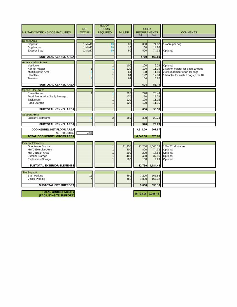
MILITARY WORKING DOG FACILITIESNO.
OCCUP
NO. OF ROOMS
REQUIRED MULTIP COMMENTSSF SM
Kennel AreaDog Run 1 MWD 10 80 800 74.32 1 room per dogDog House 1 MWD 10 16 160 14.86Exterior Slab 1 MWD 10 80 800 74.32 Optional
SUBTOTAL KENNEL AREA 1760 163.50
Administrative AreasVestibule 1 100 100 9.29 OptionalKennel Master 1 1 120 120 11.15 1 kennel master for each 10 dogsMultipurpose Area 2 1 64 128 11.89 2 occupants for each 10 dogsHandlers 3 1 64 192 17.84 1 handler for each 3 dogs(3 for 10)Trainers 1 1 64 64 5.95