Autodesk BIM Curriculum 2011 Instructor Guide Unit 2: BIM Design Process
Contents Unit Overview .....................................................................................................................3!
Key Concepts.................................................................................................................3!Lesson Roadmap ...........................................................................................................6!Software Tools and Requirements.................................................................................7!Suggested Resources....................................................................................................7!
Lesson 1: Area and Space Planning ................................................................................9!Lesson Overview............................................................................................................9!Learning Objectives .....................................................................................................10!Suggested Exercises ...................................................................................................10!Assessment..................................................................................................................15!Key Terms....................................................................................................................16!
Key Concepts Design is typically an iterative process where ideas are successively refined in a series of phases or stages, each focusing on specific aspects of the design. While the process followed by every project team will have its own unique features, the stages typically include:
• Conceptual or schematic design
• Preliminary design
• Design development
• Construction documents and details
Each of these design phases has a specific focus and questions that are typically answered before moving to later stages.
As design activities move through these stages, a top-down approach is often used. The early stages focus on high-level decisions with major impacts that will shape the options available during later stages. The later phases focus on developing and exploring the selected options and filling in the needed details.
Conceptual or Schematic Design
The conceptual design stage typically starts with a program statement that enumerates the requirements that must be fulfilled by the design. Using this program statement as a guide, the design team typically develops and evaluates several rough concepts for the overall shape, massing, orientation, and positioning of the building on the project site.
In developing these design concepts, many constraints must be considered that bound the potential building envelope. These often include site setbacks, floor area or building footprint limitations, daylight plane and shading restrictions, and other requirements imposed by local authorities and approval agencies.
Balancing the client requests and requirements and the site constraints can be a tricky task. Abstract concepts of the overall building shape and placement will be developed and evaluated, often with little detail about the precise features of the building envelope or the configuration of the rooms inside. In order to keep the design problem manageable, this top-down approach focuses on making the big decisions first, saving more detailed design decisions for a later phase.
Using the power of BIM tools, many aspects of these conceptual designs can be evaluated at even this earliest stage. For example, building performance analysis can be performed to evaluate the potential energy use of various building shapes and orientations. Design teams can use this early feedback to help guide their recommendations about the best alternative to choose.
The conceptual design options will be evaluated and presented to the clients, and once a preferred option is selected and approved, the process can move on to the next stage.
Preliminary Design
Having established the overall shape and form of the building envelope, design teams often focus on area and space planning—allocating the space within the building envelope
AUTODESK CURRICULUM
4
to the various program needs and considering various layouts for how these spaces might be organized.
During the preliminary design phase, designers will also typically articulate the features of the building envelope, proposing the exterior wall materials and assemblies, preliminary window placements, daylighting and shading features, and the roof form. Preliminary room layouts are also be created to develop the scheme for the interior spaces that will be used.
As information about the proposed design is refined and added to the building model, analysis of the proposed design can continue to guide the design. For example, during the preliminary design phase, cost estimates are often developed based on the quantities and materials specified in the model. These estimates provide valuable feedback that helps design teams evaluate the impact of potential design decisions and ultimately make better decisions.
Design Development
During the design development phase, the ideas and design features selected during the preliminary design phase are developed and explored in more detail.
For example, once the room layouts have been approved, a wide variety of interior details and finishes can be added to flesh out the design. Design alternatives for casework options and fixture placement can be considered. Special architectural treatments for interior walls or ceilings can be evaluated. While these features could have been added during an earlier phase, it makes more sense and decreases the likelihood of wasted work to add them after the preliminary design decisions are made.
Another common design activity during the design development phase is the evaluation of design options—identifying key features where the design team would like to develop and explore several alternate approaches. The flexibility of the BIM modeling process allows teams to develop alternate design ideas and evaluate them in the context of the overall proposed design. By making it easy to consider design options, teams have greater latitude to test innovative ideas and find better solutions.
During the design development phase, analysis of the building model can continue at greater detail. Cost estimates can be updated and refined. Analysis tools can be used on the building model to assist teams in creating preliminary designs for the structural and building systems (mechanical, electrical, and plumbing systems), and the impacts and interactions with these systems can be evaluated and used to improve the proposed design.
Construction Documents and Details
The construction document and detailing phase focuses on adding information to the building model to fully describe the proposed design through drawings and details that can be used to guide the construction process.
Fully documenting a proposed design at the level of detail required to guide the construction process can be a monumental task. Every feature of the building assemblies, the connection details, and the components that will be installed must be documented and presented on sheets for distribution to the project delivery team.
BIM tools can assist in this phase of the design process in several ways. The building model provides an overall framework for generating the details that must be created. Rather than drawing each detail from scratch as a series of lines, views of the model can be created that form the basis for details. Annotations and notes are added to complete
AUTODESK CURRICULUM
5
and fully explain these details, but the building model serves as a valuable starting point as well as a consistency check. Since model views are live, any changes to the building model are automatically reflected in the derived details.
While the output of the construction document phase is typically a set of printed plan sheets, the building model can be shared with the project delivery team to facilitate automated quantity takeoffs as well as conflict and interference checking. This powerful application of the BIM design process requires innovative approaches to organizing project teams and sharing risk, and these topics are explored in curriculum Unit 5, Integrated Project Delivery.
Impact of BIM on the Design Process
The use of BIM tools creates the opportunity to radically change and improve the design process in several ways. Whereas traditional 2D CAD-based design approaches focused on increasing the productivity of the construction document phase, a BIM-based design workflow changes the process in a more fundamental way by enabling the sharing and incremental enhancement of design information through all project phases.
Building modeling enables design teams to systematically assess and evaluate the performance of their designs at even the earliest stages of a project. This early feedback enables crucial and impactful design decisions to be made earlier in the process, when there is still an opportunity to make greater impact at a lower cost.
The use of a BIM-based workflow also provides a vehicle for sharing proposed designs that enables members of the design team to more easily collaborate using a live version of the building model. Rather than working in silos and passing paper-based snapshots of the design, all members of the design team can access the latest model changes and assess the impact of their design recommendations in the context of the overall design.
Impact of BIM on the Project Delivery Process
Beyond the direct benefits to the design team, a BIM-based design workflow also benefits the full project team and project delivery process.
Design is just one aspect of the total project lifecycle. Capturing building design information in a BIM model also benefits other key stakeholders, including the procurement team, the building team, and the facility managers. Each of the project functions is responsible for producing certain information assets, all of which originate from the building information captured in the design model:
Design Procure Build Manage
Preliminary Sketching
Plan, Elevation, Section, Detail Drafting
Perspectives
Renderings
Quantity Takeoffs
Purchase Orders
Shop Drawings
Reviews, Checks
Quantity Takeoffs
Cost Estimates
Schedules
Field Changes
Detail Clarifications
As-Builts
Parts Inventory
Maintenance Manuals
Maintenance and Repair Records
Tenant Improvements
Modifications, Changes, and Remodels
AUTODESK CURRICULUM
6
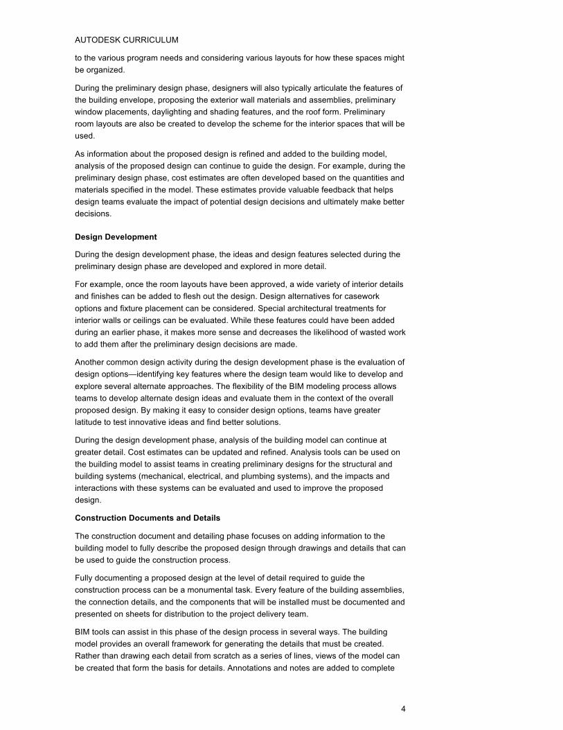
Traditionally, each of these functions has operated in silos, without much collaboration or communication until there was a need for information handoff. In paper-based workflows, those handoffs occur manually via physical construction or design documents. And the regression of the project information through these paper handoffs results in “backflows” that require rework to rebuild the project by reinterpreting the information from the drawings.
Figure 2.0.1 BIM improves the integrity of information between functions
Figure 2.0.1 illustrates how at each project phase, a set of digital assets (for example, CAD drawings) is created and knowledge is built up. In traditional paper-based workflows, these assets are used to their full potential. Converting the information into paper forms, then reinterpreting the drawings to create new digital representations creates inefficiency and invites misinterpretation.
A BIM-based design process enables the use of the building model as a conduit that can capture and coordinate knowledge developed by all participants in the process in a format that can be shared throughout the project lifecycle. In this way, information flows from one function to another occur more smoothly and with greater integrity and reliability.
Lesson Roadmap In this unit, students will learn how BIM tools can be used to support an integrated design workflow by exploring how to:
• Use area and space planning techniques to create initial layouts that fulfill program needs and meet planned space budgets.
• Specify project phases and use phased design approaches to coordinate the design process on multiphase and renovation projects.
• Create design options to consider and evaluate alternative design strategies.
• Add details and annotations to model views to create detail views that can be used in construction documents.
• Create, organize, and format schedules of building elements to present tabular summaries and support calculations using values from the model.
AUTODESK CURRICULUM
7
Software Tools and Requirements
To complete the exercises in this unit, students should download Autodesk® Revit® Architecture 2011 software from the Autodesk Education Community website and install it on their computers.
For more detailed coverage and examples of how to use Autodesk® Revit® Architecture for design tasks, students can refer to:
• Curriculum materials available on the Autodesk Education Community website.
• Autodesk® Revit® Architecture software’s extensive help system.
• Videos and tutorials available in the Revit help menu.
Suggested Resources
BIM Methodology
BIM Deployment Plan usa.autodesk.com/adsk/servlet/item?id=14652957&siteID=123112
Case Studies/White Papers
Factor Ten Engineering Introduction Link to White Paper
Factor Ten Engineering Design Principles Link to White Paper
Autodesk AEC Headquarters and Integrated Project Design, Factor Ten Engineering Case Study, August 2010 Link to White Paper
Banana Farm 1.0, Factor Ten Engineering Case Study, August 2010 Link to White Paper
10 Exchange Square, London: Information Technology for Collaboration, 2005 www.gsd.harvard.edu/people/faculty/pollalis/cases/BL-CaseStudy-mar-2005.pdf
Architecture Programs Implement Interdisciplinary Collaboration Studios to Capitalize on the Emergence of Integrated Project Delivery Link to White Paper
Autodesk Revit Architecture
Autodesk Revit Architecture 2011 User Assistance docs.autodesk.com/REVIT/2011/ENU/landing.html
Autodesk Revit Architecture Services & Support Center usa.autodesk.com/adsk/servlet/ps/index?siteID=123112&id=2956546&linkID=9243099
Autodesk BIM for Architecture, Engineering, and Construction Management 2011 Curriculum students.autodesk.com/ama/orig/bim2010/start.htm
AUTODESK CURRICULUM
8
BIM Curriculum Support and Discussion http://www.bimtopia.com/bimcurriculum.html
www.autodesk.com/edcommunity
Autodesk BIM Curriculum 2011 Instructor Guide Unit 2: BIM Design Process Lesson 1: Area and Space Planning
Lesson 1: Area and Space Planning Lesson Overview In this lesson, students explore how building modeling tools can be used to the process of area and space planning, which is often one of the first steps in the preliminary design process.
Client requirements for a project are often described in area budgets that allocate square footage targets to specific departments, programs, or functions. Designers typically use these targets as a starting point for a top-down design approach, allocating specific building areas to each of the budgets and tabulating the assignments to confirm that the program needs are being met. This approach enables designers to make high-level design decisions and assess their impact, long before the details of the individual rooms are mapped out.
As preliminary design progresses, additional details are added to the building model and the initial area allocations are typically divided into rooms with specific functions and occupancies. As the design matures, area and space planning continues in parallel with the design work to ensure that each iteration of the design continues to meets the client’s needs and requirements.
Students will follow this top-down approach to first allocate the total space available within a project into areas allocated to different uses, and then subdivide these areas into rooms with specific types to meet program needs.
Defining and Displaying Areas and Area Plans
An area is a subdivision of space within a project model. Areas are typically larger in scale than individual rooms, and area boundaries may or may not coincide with model elements, such as walls.
Area plans can help monitor if all of the necessary design objectives are being met during the early conceptual and preliminary design phases, even before the room boundaries and wall have been fixed. For example, designers often use area plans in the programming phase of a project to allocate spaces to meet the budgeted space requirements for each area type. Another common application is to use area plans to show the relationship between the core and circulation spaces in a floor plan.
Area plans can be used to calculate the areas allocated to different program requirements and needs using various calculation standards and methods. Some of the commonly used standards for area calculations include:
Gross area: The overall area of a floor or footprint of the building.
Rentable area: Individual developers and leasing companies can use different standards and rules for computing rentable areas. For example, rentable area can be defined to include all the spaces in a building except egress corridors, vertical transportation, and
AUTODESK CURRICULUM
10
mechanical spaces.
Usable area: The area in a plan that is actually usable by clients and tenants. Usable area typically excludes areas taken up by columns, walls, mechanical rooms, and shafts and other nonusable space.
BOMA area: The Building Owners and Managers Association (BOMA) has defined a set of definitions and area calculation rules that is widely used in the United States by architects, developers, and facilities managers to help standardize the process of office-building development. More information on the BOMA standards and calculation rules can be found at www.boma.org.
Defining and Displaying Rooms and Room Plans
As design progresses, building elements are added to the model that define and bound rooms. These elements typically include roofs, walls, floors, columns, and ceilings, and each of these elements have a property that determines whether it is used to determine the room extents. In open spaces, room separation lines can also be added to a model to create virtual rooms.
Designers typically create room objects within these bounding elements, and these room objects can be deleted, modified, and queried like other elements in Autodesk® Revit® products. Rooms automatically compute and report their area and can optionally be set up to also compute their volume. As with most other model elements, tags can be added to rooms to display their properties (such as area or volume) in plan views. Rooms can also appear in schedules to present key values and properties in a convenient tabular form.
While rooms are often used by designers for area and space planning, they are also used to provide information needed by other design disciplines. For example, they can be used for building performance analysis and design of mechanical systems. In this application, mechanical engineers use the room-bounding information as a starting point for determining spaces and zones for heating and cooling load analysis.
Learning Objectives After completing this lesson, students will be able to:
• Understand the importance of creating area plans that communicate how the project design meets the programmed space requirements for each end-use.
• Appreciate the value of using area schedules that calculate gross building total and subtotals.
• Appreciate how to create room layouts and schedules to a desired level of detail.
• Investigate the ways of adding custom parameters to room objects which are then reported in the room schedules.
Suggested Exercises
Exercise 2.1.1: Defining and Displaying Areas and Area Plans
In this exercise, students will learn how to:
• Create gross building type area plans with custom area type parameters and color fills.
AUTODESK CURRICULUM
11
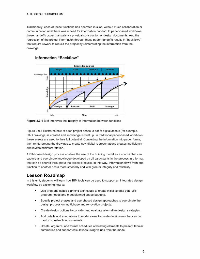
• Generate area schedules with desired fields, formatting, sorting, and grouping.
• Display the area plans with legends and schedules on sheets.
Video Tutorial
Unit2_Lesson1_Tutorial1.mp4
Student Exercise
Unit2_Lesson1_Exercise1_Start.rvt
• Create a gross building area plan for Building 2 that divides the space among five departments whose requirements are outlined below:
o Earth Systems: 4000 SF (372 square meters) o Civil Engineering: 6500 SF (604 square meters) o Architecture: 4500 SF (418 square meters) o Electrical Engineering: 3500 SF (325 square meters) o Urban Studies: 2500 SF (232 square meters)
• Use the Building 2 Area Schedule, which is already created in the project file, to verify that the program requirements are being met by your proposed area plan.
Figure 2.1.1. Creating new gross building area plans
AUTODESK CURRICULUM
12
Figure 2.1.2. Example area plan and schedule for Building 1
Exercise 2.1.2: Defining and Displaying Rooms and Room Plans
In this exercise, students will learn how to:
• Add room objects and defining new room object parameter types.
• Generate and configure room schedules that group and tally across different parameters.
• Display the room plans and schedules on sheets for sharing.
AUTODESK CURRICULUM
13
Video Tutorial
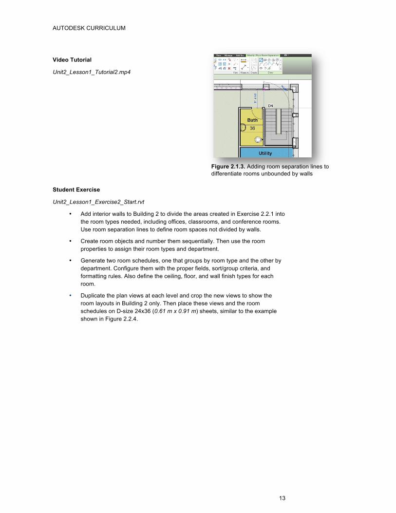
Unit2_Lesson1_Tutorial2.mp4
Student Exercise
Unit2_Lesson1_Exercise2_Start.rvt
• Add interior walls to Building 2 to divide the areas created in Exercise 2.2.1 into the room types needed, including offices, classrooms, and conference rooms. Use room separation lines to define room spaces not divided by walls.
• Create room objects and number them sequentially. Then use the room properties to assign their room types and department.
• Generate two room schedules, one that groups by room type and the other by department. Configure them with the proper fields, sort/group criteria, and formatting rules. Also define the ceiling, floor, and wall finish types for each room.
• Duplicate the plan views at each level and crop the new views to show the room layouts in Building 2 only. Then place these views and the room schedules on D-size 24x36 (0.61 m x 0.91 m) sheets, similar to the example shown in Figure 2.2.4.
Figure 2.1.3. Adding room separation lines to differentiate rooms unbounded by walls
AUTODESK CURRICULUM
14
Figure 2.1.4. Example room layout with color fill legend and room schedule
AUTODESK CURRICULUM
15
Assessment
Defining and Displaying Areas and Area Plans
• Why are areas useful in early conceptual design?
Areas enable designers to quickly subdivide and allocate space before the actual interior walls are placed.
Areas can be tagged with their square footage and tabulated in schedules to give designers immediate feedback about the space allocated in each area. They also offer great flexibility because the area boundaries can be defined arbitrarily and do not need to be defined by space bounding objects, such as walls.
• For what purposes might clients or owners want an area schedule?
To most clients, allocation of building areas is critical to the planning process. Area plans can be used to quickly verify that the space allocated to each of the design program needs has been adequately provided. They can also used to summarize key information about a proposed design (for example, the amount of rentable square footage versus common area), which is needed to evaluate the financial feasibility of the project.
• What is the essential difference between a gross building area plan and rentable area plan?
In gross building area plans, you have complete control over the placement of area boundaries. They can be placed at the interior surface, exterior surface, or middle of walls, as well as at any arbitrary location in an area plan view.
By contrast, in rentable area plans, the area boundaries are picking walls and allowing Revit to use the BOMA rules to determine the placement of the separation lines based on the uses of the adjacent spaces.
Defining and Displaying Rooms and Room Plans
• How can the room type allocations be used to generate a preliminary cost estimate for the furnishings and interior finishes?
For each different room type we can define an estimated cost per square foot for furnishings and interior finishes. Then using the area of each room and the room type, you can use the room schedule to calculate the furnishing and finish costs and subtotal these for the project.
• How might the occupancy field be used in preliminary design?
The occupancy field captures the planned number of occupants for each room. This can be used to tabulate the number of users that will be served by the spaces in the proposed design. It can also be used for system design, as well as circulation, egress, and safety planning.
• How are the wall, floor, and ceiling finish fields that appear in the room schedule typically used?
The room finish fields enable designers to quickly specify the surface finishes for each room in the proposed design. The tabular format of the room schedule helps make it easy to spot mistakes or omissions and to summarize the total
AUTODESK CURRICULUM
16
area required for each of the finish materials. Room finishes are often described through reference type codes (for example, Wall Finish A or Floor Type B) that can be easily defined or changed later in the design process.
Key Terms The following key terms were used in this lesson:
Key Term Definition
Area Plan Views that show spatial relationships based on area schemes and levels in your model. You can have multiple area plans for every area scheme and level.
Schedule A tabular display of information, extracted from the properties of the elements in a project. A schedule can list every instance of the type of element being scheduled, or it can collapse multiple instances onto a single row, based on the schedule’s grouping criteria.
Room A defined space in a building, used for a specific purpose and separated from other areas by walls, partitions, or room separation lines.
Room-Bounding Elements
A model element that defines a boundary of a room, such as walls, partitions, floors, ceilings, and roofs.
.
www.autodesk.com/edcommunity
Autodesk BIM Curriculum 2011 Student Workbook Unit 2: BIM Design Process Lesson 2: Project Phases and Phased Design
Lesson 2: Project Phases and Phased Design Lesson Overview Many projects, whether new construction or renovations, are designed and constructed in distinct phases. These phases can represent either the time periods themselves or the state of the project at specific points in time.
In this lesson, students explore two applications of project phases and phased design and will learn how to:
• Use project phases to organize the information in a building model based on the project phases during which different portions will be constructed.
• Use project phases to coordinate the elements in a renovation project and display accurate views of the as-built conditions, demolition work, and proposed new design.
By defining project phases and using phase-based filters to determine the information presented in model views, the building model can be used to facilitate design and visualization at each of the stages in the project lifecycle.
Modeling Phased Projects in Autodesk Revit
Phases are distinct, separate time periods or “milestones” within a project. Every project includes at least one phase, and by default, Autodesk® Revit® software defines two phases (named Existing and New Construction) in new projects. The project team can rename these phases or add as many phases as needed to accurately describe the project.
All elements in the building model have two properties that control the time periods during which the element is considered to be present—Phase Created and Phase Demolished. In project phases before the Phase Created or after the Phase Demolished, the element is ignored and will not be displayed in model views.
The visibility of model elements in any view is determined by a combination of the Phase property for that view and a Phase Filter that determines how elements will be displayed based on their creation and demolition state relative to the current phase. Every element is assigned a status relative to the phase of the current view:
• New—If the element was created in the phase of the current view
• Existing—If the element was created in an earlier phase and continues to exist in the current phase
• Demolished—If the element was created in an earlier phase and demolished in the current phase
• Temporary—If the element was created and demolished during the current phase
AUTODESK CURRICULUM
18
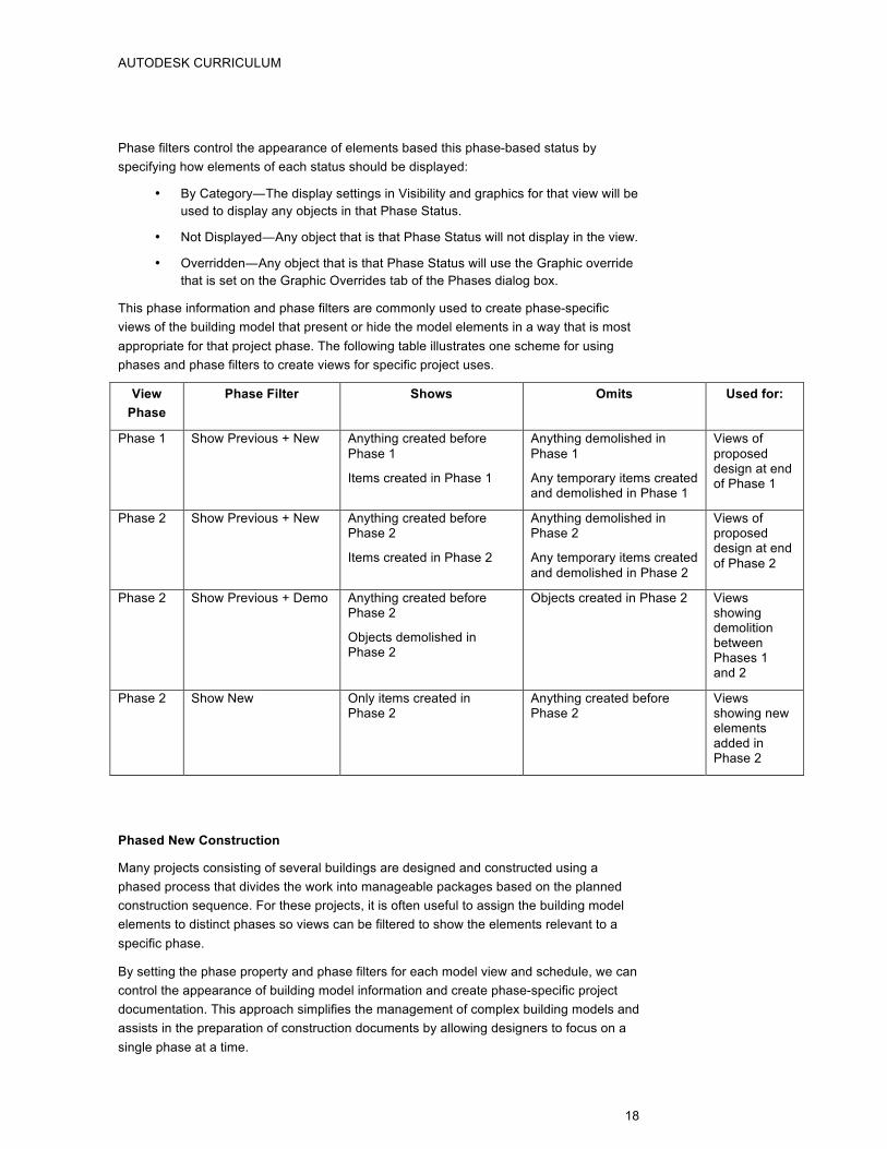
Phase filters control the appearance of elements based this phase-based status by specifying how elements of each status should be displayed:
• By Category―The display settings in Visibility and graphics for that view will be used to display any objects in that Phase Status.
• Not Displayed―Any object that is that Phase Status will not display in the view.
• Overridden―Any object that is that Phase Status will use the Graphic override that is set on the Graphic Overrides tab of the Phases dialog box.
This phase information and phase filters are commonly used to create phase-specific views of the building model that present or hide the model elements in a way that is most appropriate for that project phase. The following table illustrates one scheme for using phases and phase filters to create views for specific project uses.
View Phase
Phase Filter Shows Omits Used for:
Phase 1
Show Previous + New Anything created before Phase 1
Items created in Phase 1
Anything demolished in Phase 1
Any temporary items created and demolished in Phase 1
Views of proposed design at end of Phase 1
Phase 2
Show Previous + New Anything created before Phase 2
Items created in Phase 2
Anything demolished in Phase 2
Any temporary items created and demolished in Phase 2
Views of proposed design at end of Phase 2
Phase 2
Show Previous + Demo Anything created before Phase 2
Objects demolished in Phase 2
Objects created in Phase 2 Views showing demolition between Phases 1 and 2
Phase 2
Show New Only items created in Phase 2
Anything created before Phase 2
Views showing new elements added in Phase 2
Phased New Construction
Many projects consisting of several buildings are designed and constructed using a phased process that divides the work into manageable packages based on the planned construction sequence. For these projects, it is often useful to assign the building model elements to distinct phases so views can be filtered to show the elements relevant to a specific phase.
By setting the phase property and phase filters for each model view and schedule, we can control the appearance of building model information and create phase-specific project documentation. This approach simplifies the management of complex building models and assists in the preparation of construction documents by allowing designers to focus on a single phase at a time.
AUTODESK CURRICULUM
19
Phased Renovations
Another common design situation in which project phasing can be useful is renovations or retrofits of existing structures. Renovations are typically modeled using two phases:
• Existing—which is used to model the existing as-built conditions
• New Construction—which is used to model the proposed design
Demolition is typically not modeled as a separate phase. Rather, it is better practice to indicate the building elements to be demolished by setting the Phase Demolished property for these elements to the New Construction phase. Demolition plans can then be created by using a phase filter to display and highlight the elements to be demolished.
An important consideration to keep in mind while modeling renovation projects is that building elements can only be created or demolished between phases. When only a portion of a building element should be demolished, it is often helpful to split that element into individual parts, so that each segment can be treated separately.
Building elements created in prior phases should not be edited, stretched, reshaped, or deleted because these operations will change their appearance in all phases. This limitation mirrors the physical reality of how objects can change between phases—you can typically create new objects and demolish existing ones, but physical elements typically cannot be stretched to a new configuration.
Learning Objectives After completing this lesson, students will be able to:
• Appreciate the importance of deciding in early stages how many phases they need, what to name them, and how to order them.
• Appreciate the method of setting up individual views to show only the desired phases and to generate temporal snapshots of the project.
• Understand how to attribute phases properties―phase created and phase demolished―to objects and to attribute phase and phase filters to views.
• Explore how to model elements in the correct phase filtered view to correspond with the phase you are editing or adding to.
• Appreciate techniques of modeling that accurately represent, in practical construction terms, how they change through the project.
Suggested Exercises
Exercise 2.2.1: Phased New Construction
In this exercise, students will learn how to:
• Enable phases and define the necessary phases for a given project.
• Set up phase-specific views with phase filters applied in order to accurately represent the state of project at any given time.
• Assign phase properties of model elements to properly represent when each structure will be built relative to the others.
• Adjust graphics overrides for phase filters to display as desired.
AUTODESK CURRICULUM
20
Video Tutorial
Unit2_Lesson2_Tutorial1.mp4
Student Exercise
Unit2_Lesson2_Exercise1_Start.rvt
• Add another phase to the project and name it Phase 3.
• Duplicate the existing views (plan views, elevations, and 3D views) of Phase 2 to create two sets of new views for Phase 3, setting the Phase and Phase Filter properties to show these states:
o Phase 3 Planning: Use the Previous + New phase filter to override elements from previous phases and display them in gray.
o Phase 3 Complete: Use the Show Complete phase filter to display elements from all three phases by category.
• Open the new Phase 3 views and place building elements (walls, doors, windows, roofs, and so on) to construct the envelope of a third building in the space indicated.
• Open the views for the prior phases and verify that your new building elements appear only in the views for Phase 3.
Figure 2.2.2. Adding a new phase to the project
Figure 2.2.1. Setting the phase filter to Show Previous + New model elements
AUTODESK CURRICULUM
21
Exercise 2.2.2: Phased Renovations
In this exercise, students will learn how to:
• Set up the phase-specific views in order to model construction for a renovation or remodel.
• Perform the demolition operations on model elements to make way for the elements in the new construction.
• Create model elements that have correctly defined phase parameters.
Video Tutorial
Unit2_Lesson2_Tutorial2.mp4
Student Exercise
Unit2_Lesson2_Exercise2_Start.rvt
• Open the proposed plan view of the home remodel, and demolish the building elements located in the bedroom wing of the residence.
• Place elements (walls, doors, windows, roofs, and so on) in the project model to illustrate a proposed design for the bedroom suite addition.
• As you place new elements, be certain not to delete, stretch, or edit existing building elements. To accurately model a renovation project, elements should only be demolished or created.
• Place the floor plan views and elevations showing each of the project states (as built, demolition, and proposed) on D-size 24x36 (0.61 m x 0.91 m) sheets, cropping and scaling the views as needed to fit on the sheets.
o Place all of the four elevations on one sheet.
o Place the floor plan on a separate sheet.
Figure 2.2.3. New elements placed in kitchen during renovation phase
AUTODESK CURRICULUM
22
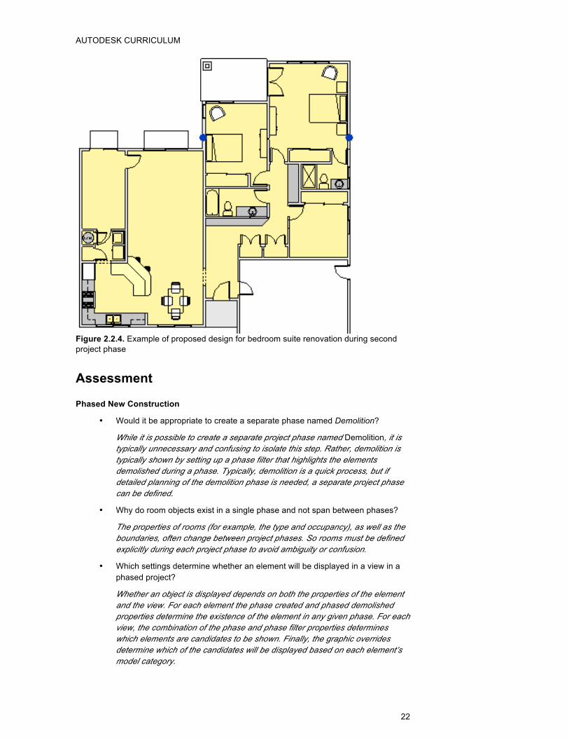
Figure 2.2.4. Example of proposed design for bedroom suite renovation during second project phase
Assessment
Phased New Construction
• Would it be appropriate to create a separate phase named Demolition?
While it is possible to create a separate project phase named Demolition, it is typically unnecessary and confusing to isolate this step. Rather, demolition is typically shown by setting up a phase filter that highlights the elements demolished during a phase. Typically, demolition is a quick process, but if detailed planning of the demolition phase is needed, a separate project phase can be defined.
• Why do room objects exist in a single phase and not span between phases?
The properties of rooms (for example, the type and occupancy), as well as the boundaries, often change between project phases. So rooms must be defined explicitly during each project phase to avoid ambiguity or confusion.
• Which settings determine whether an element will be displayed in a view in a phased project?
Whether an object is displayed depends on both the properties of the element and the view. For each element the phase created and phased demolished properties determine the existence of the element in any given phase. For each view, the combination of the phase and phase filter properties determines which elements are candidates to be shown. Finally, the graphic overrides determine which of the candidates will be displayed based on each element’s model category.
AUTODESK CURRICULUM
23
Phased Renovations
• How can you demolish a portion of an existing wall or building element?
If an element can be split, you can break the single element into parts: the part to keep and the part to demolish. Once split, you can demolish the appropriate part.
• What happens when a hosted object is demolished, such as a door or window?
When you demolish a hosted object, such as a door or window, Autodesk® Revit® software automatically fills in the opening that was created to host that object. This models real-world behavior. Demolishing a window, for example, typically involves patching the opening with the adjacent wall materials.
• How could you apply phases to schedules, which are essentially just another model view?
For example, in a large renovation project, a door schedule would usually list all doors created in the project. In a building with hundreds of doors, the schedule could become difficult to work with because the demolished doors would be listed with the post-renovation doors. It is typically better to create separate pre-demolition and post-renovation schedules by applying the appropriate phase and phase filters to each.
Key Terms The following key terms were used in this lesson:
Key Term Definition
Project Phase A distinct time period in the life of the project.
Phase Filter A phase filter is a rule that you apply to a view to control the display of elements based on their phase status. Filters can specify that elements be displayed by category, overridden, or not shown.
Graphic Override A rule that specifies how overridden elements be displayed based on their phase status.
Phase Status The status of each building element relative to the phase specified for the current view. Each phase status typically has a different display style associated with it to make it easy to identify the phase status of the elements in a view.
Existing The phase status assigned to elements that were created in an earlier phase and continues to exist in the current phase.
Demolished The phase status assigned to elements that were created in an earlier phase and demolished in the current phase.
New The phase status assigned to elements that were created in the phase of the current view.
Temporary The phase status assigned to elements that were created and demolished during the current phase.
www.autodesk.com/edcommunity
Autodesk BIM Curriculum 2011 Student Workbook Unit 2: BIM Design Process Lesson 3: Design Options
Lesson 3: Design Options Lesson Overview In this lesson, students experience the process of identifying areas of a project where multiple design options are being considered and a workflow for exploring, evaluating, and presenting those options within a single integrated design model.
The suggested exercises present two examples of varying scales; they:
• Consider options for the design of an entire building wing.
• Compare alternatives for room layouts in a portion of a building.
Defining Option Sets and Options Within Each Set
Designers often explore many options and possible alternatives to particular design problems in their quest for the best design solutions. For example, designers might consider several options to:
• Fit out and furnishing an interior space
• Provide a landmark canopy over the entrance to a building
• Articulate the balcony railings on a prominent building façade
A BIM-based design process enables designers to define key features or areas where sets of design options will be considered and manage the proposed options in the context of the overall design. Designers can define as many options sets as needed to evaluate proposed design alternatives—there is no limit.
Rather than maintaining separate models for each of the proposed options, a single model is used to coordinate the design of all options. The main building model includes all the elements that are fixed—that is, not affected by the options being explored—and thus, acts as a backdrop in which the design options can be evaluated. This single model approach ensures consistency as the design progresses and continues to evolve.
Presenting and Comparing Design Options
Separate views are typically created that display each design option in the context of the main model for presentation to the design team, clients, and other stakeholders in the review process. These views can be presented individually or placed on a single sheet for easy comparison.
One of the options in each design option set is assigned to be the primary option or leading candidate among the options being considered. By default, the features of this option are displayed in model views. To easily see and consider additional design options, views can be duplicated and each view can be set to display a specific design option.
This ability to display the elements in specific design options extends to all model views including schedules. This powerful feature enables design options to be fully evaluated in both graphical and tabular views. For example, one wall schedule can tabulate data for
AUTODESK CURRICULUM
25
the primary option and another wall schedule can present the revised data for a secondary option.
After the design options have been considered and the preferred option has been selected, that option can be accepted as the primary design solution and moved back into the main model. When a design option is accepted, elements in the other design options are removed from the building model to reduce the file size and improve model efficiency. This approach is recommended if you have made a definite design decision and intend to move forward with that decision. Keeping unused and out-of-date options in the project needlessly inflates the file size and adds unwanted complexity.
Learning Objectives After completing this lesson, students will be able to:
• Explore how to define new design option sets and experiment with design. alternatives
• Appreciate how to present each design option in separate views.
• Understand how to choose a design option as the final solution and discard the other alternatives.
Suggested Exercises
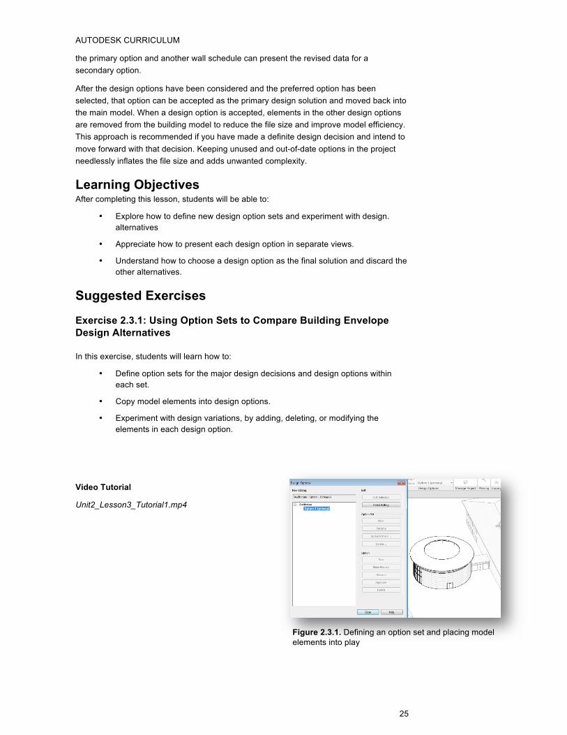
Exercise 2.3.1: Using Option Sets to Compare Building Envelope Design Alternatives
In this exercise, students will learn how to:
• Define option sets for the major design decisions and design options within each set.
• Copy model elements into design options.
• Experiment with design variations, by adding, deleting, or modifying the elements in each design option.
Video Tutorial
Unit2_Lesson3_Tutorial1.mp4
Figure 2.3.1. Defining an option set and placing model elements into play
AUTODESK CURRICULUM
26
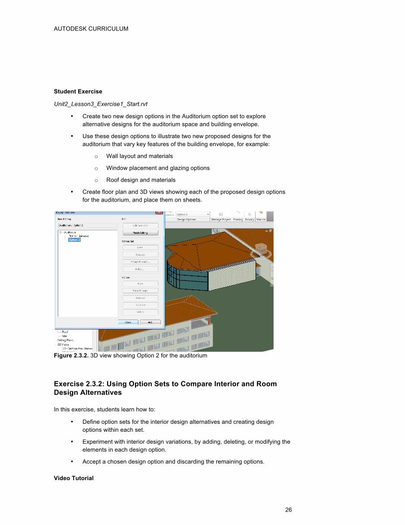
Student Exercise
Unit2_Lesson3_Exercise1_Start.rvt
• Create two new design options in the Auditorium option set to explore alternative designs for the auditorium space and building envelope.
• Use these design options to illustrate two new proposed designs for the auditorium that vary key features of the building envelope, for example:
o Wall layout and materials
o Window placement and glazing options
o Roof design and materials
• Create floor plan and 3D views showing each of the proposed design options for the auditorium, and place them on sheets.
Figure 2.3.2. 3D view showing Option 2 for the auditorium
Exercise 2.3.2: Using Option Sets to Compare Interior and Room Design Alternatives
In this exercise, students learn how to:
• Define option sets for the interior design alternatives and creating design options within each set.
• Experiment with interior design variations, by adding, deleting, or modifying the elements in each design option.
• Accept a chosen design option and discarding the remaining options.
Video Tutorial
AUTODESK CURRICULUM
27
Unit2_Lesson3_Tutorial2.mp4
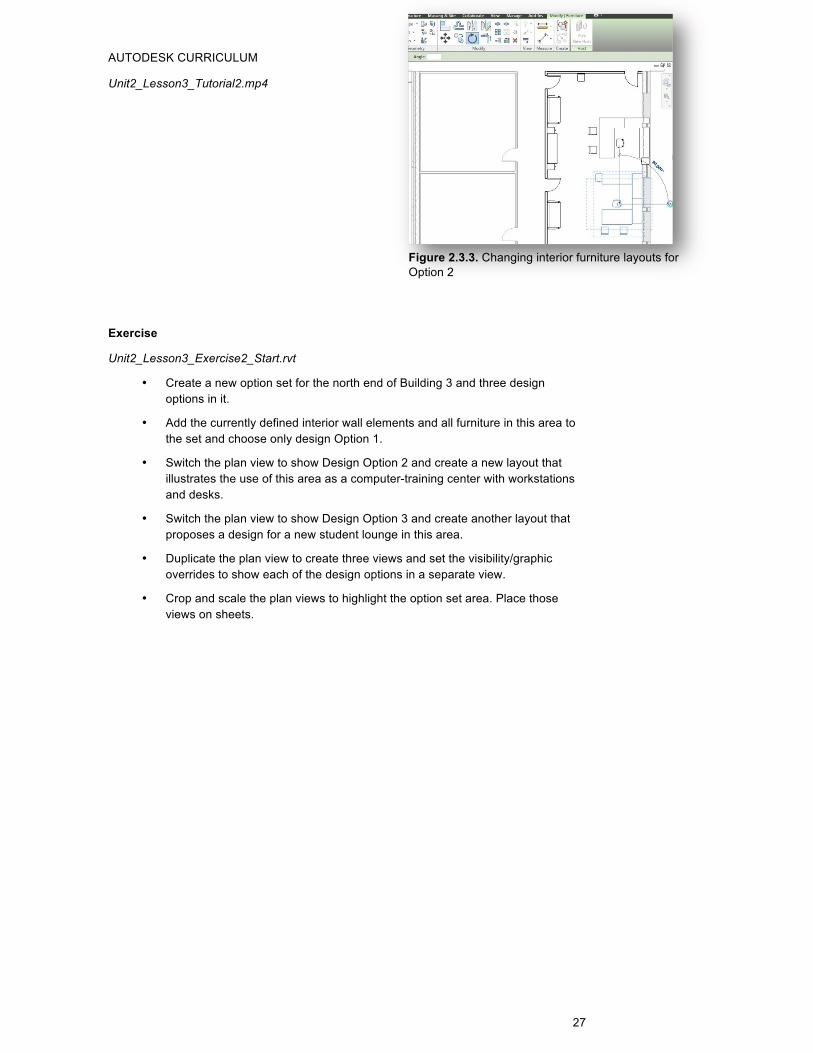
Exercise
Unit2_Lesson3_Exercise2_Start.rvt
• Create a new option set for the north end of Building 3 and three design options in it.
• Add the currently defined interior wall elements and all furniture in this area to the set and choose only design Option 1.
• Switch the plan view to show Design Option 2 and create a new layout that illustrates the use of this area as a computer-training center with workstations and desks.
• Switch the plan view to show Design Option 3 and create another layout that proposes a design for a new student lounge in this area.
• Duplicate the plan view to create three views and set the visibility/graphic overrides to show each of the design options in a separate view.
• Crop and scale the plan views to highlight the option set area. Place those views on sheets.
Figure 2.3.3. Changing interior furniture layouts for Option 2
AUTODESK CURRICULUM
28
Figure 2.3.4. Interior model elements added to Option 1 of Interior Fit out Option Set
Assessment
Using Option Sets to Compare Building Envelope Design Alternatives
• What building features would typically be changed as building envelope alternatives are explored?
Some building features that could be explored through design alternatives include wall layout and materials, window placement and glazing choices, roof form and materials, as well as the design of terraces, exterior spaces, and entries.
• How are elements that have been added to the options sets different from the main model?
As elements are added to option sets, copies of the elements are made in each of the chosen design options. This cloning allows you to make changes to the copied elements in each option independently. For example, changes made to the copied elements in Option 1 do not affect the copied elements in Option 2. By contrast, any changes to elements in the main model appear in all of the design options.
• How is the primary option different from the other design options?
The primary option is the one option that is displayed in views by default (unless a specific option is selected in the visibility graphics overrides for a view). This is often confusing for users, so it is typically better to create separate views and assign the design option specified in each explicitly.
The other key difference is that the primary option can be accepted as the choice for an option set and other options will be discarded. Before an option can be accepted, it must be made primary.
AUTODESK CURRICULUM
29
Using Option Sets to Compare Interior and Room Design Alternatives
• Can hosted elements (for example, windows and doors) be added to a design option?
In order to add hosted elements to a design option, the hosting element (for example, the wall) must also be added to the design option.
• When design options are used, which elements appear in room, door, and window schedules?
Schedules are like any other view and display the elements determined by the view settings. If a design option is specified in the visibility/graphics overrides, the elements in that option will be displayed in the schedule. Otherwise, the elements in the primary option for the option set are displayed.
Key Terms The following key terms were used in this lesson:
Key Term Definition
Option Set A collection of design alternatives that focus on a particular aspect or feature of the design.
Design Option An alternative design solution for a specific feature or problem. Design options are grouped into option sets.
Active Option The design option that you are currently editing. Elements in other options are hidden from view.
Primary Option The currently selected default design option, which is displayed in views by default (where a specific option has not been specified).
www.autodesk.com/edcommunity
Autodesk BIM Curriculum 2011 Student Workbook Unit 2: BIM Design Process Lesson 4: Detailed Design/Construction Documents
Lesson 4: Detailed Design/ Construction Documents Lesson Overview Creating detailed construction documents marks the beginning of the conversion of a proposed design into a constructible project. No drawing set is complete without descriptions of the materials and the assembly details, which is why adding annotations, linework, and detail components is a crucial phase of the complete BIM workflow.
The process of detailing is often used to present:
• Project information not captured in the building model. • Information that goes beyond the level of detail represented in the building
model. • Revisions or corrections needed to clean up the display of model elements.
The following annotation categories are often added to model views to transform them into fully functional construction: dimensions, detailing (detail lines, regions, components, revision cloud, and detail group), text, element and view tags, and symbols. Annotations and drafting detail are view-specific and do affect the underlying building model.
Here we will.
In this lesson, students explore the progressive layering of detail describing the construction of a single wall and its features by creating a building section, drilling down to a wall section, and creating details to illustrate the key connections between the wall and other building elements.
Creating Annotated Section Views
The detailing process often begins by creating section views of the entire building and specific wall assemblies.
Building sections often serve as road maps that point the way to related wall sections and connection details. Wall sections typically display the detailed layers in a wall assembly and how they connect to other building elements.
Since these section views are automatically updated when changes are made to model elements, internal consistency of the model views is ensured. The BIM methodology can save a great deal of time otherwise spent cross-referencing changes and looking for consistency errors that are typical in paper-based workflows.
Creating Details and Callouts
Detail views are typically added to a set of construction documents to present information at a larger scale or a finer level of detail needed to accurately understand specific elements and connections between elements. Although detailing can be a tedious
AUTODESK CURRICULUM
31
process, it is an essential step in converting designs into realizable construction documents.
Details bridge the gap between design and construction, conveying crucial information to the builders and contractors about how a design should be built. While it would be unrealistic to try to model every single construction detail in 3D, details enable design professionals to quickly convey practical assembly information in an easily shared 2D form.
Using Autodesk® Revit® software, details can be created in two ways:
• Detailed Model Views display the actual building model geometry at a larger scale. Detailed model views are created by adding callouts or section cuts to other views.
• Drafting Views can be generated from scratch, independent of the building model, or by importing an image or CAD detail as a starting point.
It is common practice to incorporate details from product manufacturers or even standard details from an office library in the project drawings. Drafting views provide a convenient vehicle for including this model independent information into the project.
References to details can be placed on larger-scale views using view tags, such as callout tags or section tags. These callouts and section tags provide markers that lead to the detail views and increase the coherence and usability of the document sets by pointing users from one view to other related views. Therefore, we should plan our use of views and callout or section tags to provide a logical sequence moving from large-scale view to greater levels of detail.
View Tags
View tags (such as elevation tags, section tags, and callout tags) provide pointers to related views in two ways:
• Double-clicking a view tag opens the referenced view in a manner similar to a hyperlink.
• Information about where a view has been placed on sheets is displayed in the view tag. The tag shows both the sheet number and the view number relative to that sheet.
View tags are dynamically updated to show the proper sheet number and view number as views are placed or moved between sheets. This real-time coordination prevents errors in cross-referencing, thus creating more reliable documents and saving costly rework.
Learning Objectives After completing this lesson, students will be able to:
• Explore the many ways we add detail and annotation to our views.
• Appreciate what level of detail is appropriate and how to create duplicate versions of views with varying level of details for different audiences.
• Understand how to place the views onto sheets, to modify their appearance or scale, and to enhance by adding schedules.
• Investigate the automated cross-referencing that occurs between sheets and views.
AUTODESK CURRICULUM
32
Suggested Exercises
Exercise 2.4.1: Creating Annotated Section Views
In this exercise, students will learn how to:
• Create building sections showing an overview of the interaction between building elements.
• Use a building section as a map referencing more detailed views.
• Create wall sections to display typical wall assemblies and connections.
Video Tutorial
Unit2_Lesson4_Tutorial1.mp4
Student Exercise
Unit2_Lesson4_Exercise1_Start.rvt
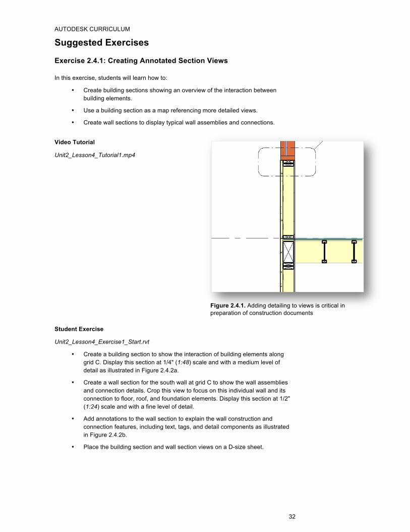
• Create a building section to show the interaction of building elements along grid C. Display this section at 1/4" (1:48) scale and with a medium level of detail as illustrated in Figure 2.4.2a.
• Create a wall section for the south wall at grid C to show the wall assemblies and connection details. Crop this view to focus on this individual wall and its connection to floor, roof, and foundation elements. Display this section at 1/2" (1:24) scale and with a fine level of detail.
• Add annotations to the wall section to explain the wall construction and connection features, including text, tags, and detail components as illustrated in Figure 2.4.2b.
• Place the building section and wall section views on a D-size sheet.
Figure 2.4.1. Adding detailing to views is critical in preparation of construction documents
AUTODESK CURRICULUM
33
Figure 2.4.2a. Example of building section showing annotations and wall section callout
Figure 2.4.2b. Example of wall section showing annotations and detail components
Exercise 2.4.2: Creating Details and Callouts
In this exercise, students will learn how to:
• Use callouts to create detailed model views and adding annotations to these views.
• Create drafting views to illustrate standard details and present views independent of the model.
• Use callouts to reference drafting views.
AUTODESK CURRICULUM
34
• Understand how the information presented a view tag is updated as views are placed on sheets.
Video Tutorial
Unit2_Lesson4_Tutorial2.mp4
Student Exercise
Unit2_Lesson4_Exercise2_Start.rvt
Manufacturer_Window_Head_Detail.dwg
• Create a callout showing a detailed model view of the area at the center of the wall section created in Exercise 2.4.1 focusing on the wall-to-second floor connection.
o Set the view type to Detail.
o Set the view scale to 1 ½” = 1’-0” (1:8).
• Add detail components, adjust the filled regions, and add text notes explaining the essential framing elements and building details:
o Use Nominal Cut Lumber-Section:6x12 (0.14 m x 0.29 m) for the rim beam.
o Use Nominal Cut Lumber-Section:2x6 (0.04 m x 0.14 m) for the bottom plate of the second floor wall, and two of this component for the double top plate of the first floor walls.
o Use Wood I Joist-Section:2 5/16x11 7/8 (0.06 m x 0.30 m) for the floor joists.
o Adjust the cut profile for gypsum wall board layer of the wall elements on first and second floors as shown to eliminate the overlap with the intersecting floor element. Also adjust the cut profile of the finish layer of the floor assembly to remove the overlap with the wall framing layers.
o Add a detail component representing the molding at the base of the wall. Use Base Molding-Section and choose the 3/4”x 4” (0.02 m x 0.10 m) type.
o Add 5 ½” (0.14 m) thick insulation to the upper and lower walls.
o Add text notes notes as shown in Figure 2.4.4.
Figure 2.4.3. Calling out a detail for a wall-to-slab connection
AUTODESK CURRICULUM
35
Figure 2.4.4. Example of callout view showing wall-to-floor connection details
• Create a new drafting view for a standard detail of a typical window header.
o Name this view Window Header - Typical.
o Set the view scale to 3” = 1’-0” (1:4).
• Import a CAD file (Manufacturer_Window_Head_Detail.dwg) containing the manufacturer’s standard window header detail. The file is located in the same folder as the exercise file.
• Add filled regions, detail compoments, and annotations to develop the full detail as shown in Figure 2.4.5.
o Create filled regions representing the layers of the wall assembly:
1/2 inch (13 mm) gypsum wall board
5 1/2 inch (140 mm) stud framing
1/2 inch (13 mm) plywood
7/8 inch (22 mm) stucco
o Add detail components:
Use Nominal Cut Lumber-Section:6x8 (0.14 m x 0.19 m) for the typical window header.
Use Common Wood Nails Side:10 penny for the nails at the window flange.
o Add a fill region to represent caulking between the window and the gypsum wall board.
o Edit the fill region for the gypsum wall board to wrap around the header component and into window opening to meet caulking.
• Add text notes similar to those shown in Figure 2.4.5.
• Add Break Line components at top and bottom of the detail.
• Place on sheet S3 – Wall Details.
AUTODESK CURRICULUM
36
• Add a callout to the Wall Section A view to reference the new drafting view. Enable the Reference other view option, and choose Drafting View: Window Header – Typical from the list.
• Place both of these details on a Sheet S3 – Wall Details and observe how the view tags update with the sheet and view numbers referencing the placement location.
Figure 2.4.5. Example of drafting view showing typical window header details
Assessment
Creating Annotated Section Views
• What is the essential difference between annotations and model elements?
Model elements represent true model objects and any changes to them are immediately reflected in all views in which they appear. Annotations are view-specific. They can be copied between views, but each annotation remains independent and can be changed in each view.
• Are annotations in a view static or dynamic?
All dimensions are dynamic and are automatically updated as the model elements they reference are moved or resized. Dimensions can be locked to constrain the movement of model elements and prevent further changes.
Text is typically static and is not updated as model elements change. One exception is keynotes, which will update in views if the underlying keynote is changed.
Tags are dynamic and are updated as the underlying values in the model database are changed.
• Can we annotate views dedicated to specific design options or phases?
Yes. Annotations can be added to any views to explain the unique features of specific design options or projects phases.
• How can annotations placed in a specific view be reused in other similar views?
Annotations can be copied to the clipboard and pasted into other views. Another strategy is to duplicate an existing view with detailing, thus creating a new view that include all the annotation. Finally, we can export a view including its annotations as DWG file and import it into another project.
AUTODESK CURRICULUM
37
Creating Details and Callouts
• What are the advantages and disadvantages of using drafting views versus detailed model views?
Drafting views offer a quick way of incorporating information, but since they are not linked to the model, they do not ensure consistency as the model changes. Detailed model views use the underlying model to generate the geometry shown. While this provides the benefit of propagating changes, it also requires you to verify the accuracy of the added annotations relative to the dynamic model elements.
• If a view tag does not show a view and sheet number, what does this indicate?
Empty view tags indicate that the referenced view has not yet been placed on a sheet. The tag will be filled in with the view and sheet number when the view is placed.
• Can a view be referenced by more than one callout?
Yes. When placing a callout you can choose to create a new detailed model view or to reference an existing view, including drafting views and detailed model views. It is common practice to place callouts referencing a detail at all locations where the detail information is relevant.
Key Terms The following key terms were used in this lesson:
Key Term Definition
Construction Documents Documents that communicate all of the building information and construction details required to construct the design.
Detailing The process of adding layers of information to a project to clearly explain how the proposed design should be constructed.
Annotations View-specific elements (such as symbols, tags, keynotes, and dimensions) used to add information to the views and describe the elements displayed.
Callouts (Callout Mark) Tags referencing related views in a project.
Section Views Views that cut vertically through the model and are particularly handy for wall and building sections.
AUTODESK CURRICULUM
38
www.autodesk.com/edcommunity
Autodesk BIM Curriculum 2011 Student Workbook Unit 2: BIM Design Process Lesson 5: Detailed Design/Schedules and Quantities
Lesson 5: Detailed Design/Schedules and Quantities Lesson Overview In this lesson, students explore ways to create tabular views called schedules and summarize information about the building elements through groupings, sorting, and calculating values.
One of the key benefits of the BIM workflow is the ability to manage not only the drawings, but also the tabular information in the project database. With BIM, users can dynamically generate and update schedules of building elements to support many purposes, including to:
• Improve the visibility and predictability of costs and material quantities.
• Facilitate construction management tasks, such as cost estimating and procurement.
• Summarize building performance and LEED certification data.
Since the information flow in Autodesk® Revit® products is bidirectional, the data from changes in the model flows automatically into the schedule, and changes in the schedule automatically flow back into the model. The model data can be edited through our schedules, and this technique should be used when it is easier or more efficient than doing so selecting and changing elements in graphical model views.
Creating and Presenting Models through Schedules
A schedule presents a tabular view of the project data, which can be filtered, grouped, and formatted to fit your needs. Schedules can list every instance of the building elements or collapse multiple instances into single rows, based on the schedule’s grouping criteria. Since Revit software products create a database of the elements, building a schedule is similar to creating a database query.
Schedules should be formatted to meet the needs of the end-user, whether they are engineers, designers, clients, or code officials. Schedules are often placed on sheets either alone or accompanied by the corresponding model view. Finally, schedules can be exported to many formats, including delimited text files compatible with spreadsheet software and database formats.
Enhancing and Adding Information to Schedules
By adding information, or “intelligence,” to schedules, we optimize the workflow and maximize the utility of the building model. In this way, enhanced schedules can be the basis of analysis for many goals of project.
Since model elements store all information about their physical properties, we can add information fields or parameters to model element type―for example, type mark, size, material, fire rating, and any other custom data fields we need. These parameters can be
AUTODESK CURRICULUM
40
either user entered, such as text fields, or calculated values that depend on other parameters.
Adding calculated values to schedules helps avoid errors and unnecessary time spent performing manual calculations. A simple example of a calculated value formula would be a width parameter set to equal twice the height of an object. In practice, formulas can be used in many ways, both simple and sophisticated. For example, formulas can be used to:
• Calculate area or volume of geometry. • Create a clearance dimension parameter controlled by element size. • Convert continuously variable values into integer values. • Add shelves as the height of casework increases. • Add diagonals in an open web joist as the length increases.
Formula Guidelines
Formulas support the following arithmetic operations: addition, subtraction, multiplication, division, exponentiation, logarithms, and square roots. Formulas also support the following trigonometric functions: sine, cosine, tangent, arcsine, arccosine, and arctangent.
The valid formula abbreviations for arithmetic operations and trigonometric functions are:
Lastly, we can even introduce conditional statements to our schedules. A conditional statement uses the following structure: IF (<condition>, <result-if-true>, <result-if-false>). And it means that the values entered for the parameter depends on whether the condition is satisfied (true) or not satisfied (false).
Conditional statements can contain numeric values, numeric parameter names, and Yes/No parameters. You can use the following comparisons in a condition: <, >, =. You can also use Boolean operators with a conditional statement: AND, OR, NOT. Currently, <= and >= are not implemented. To express such a comparison, we can use a logical NOT. For example, a<=b can be entered as NOT(a>b).
AUTODESK CURRICULUM
41
The following are sample formulas that use conditional statements.
Simple IF: =IF (Length < 3000mm, 200mm, 300mm)
IF with a text parameter: =IF (Length > 35', “String1”, “String2”)
IF with logical AND: =IF ( AND (x = 1 , y = 2), 8 , 3 )
IF with logical OR: =IF ( OR ( A = 1 , B = 3 ) , 8 , 3 )
Embedded IF statements: = IF ( Length < 35' , 2' 6" , IF ( Length < 45' , 3' , IF ( Length < 55' , 5' , 8' ) ) )
IF with Yes/No condition: = Length > 40 (Note that both the condition and the results are implied.)
Learning Objectives After completing this lesson, students will be able to:
• Explore the application of schedule configuration rules to create schedules to meet various audiences and information needs.
• Understand how to use the completed schedule to edit the model through BIM’s bidirectional information flow.
• Appreciate the value of adding custom information to model elements, thus making our model “smarter,” in ways that can enable schedules to host and be the basis for useful engineering calculations.
• Explore various modes of exporting the schedules to be shared and used by other team members.
Suggested Exercises
Exercise 2.5.1: Creating and Presenting Model Schedules
In this exercise, students will learn how to:
• Create schedules of model elements such as doors, windows, roofs, walls, curtain walls, furniture objects, and so on.
• Configure schedules by changing their fields, sorting logic, grouping, and format.
• Place schedules into printable sheets either alone or with appropriate graphical displays.
• Export the schedules in common formats, such as delimited text files, which can be used in Microsoft® Excel®.
Video Tutorial
Unit2_Lesson5_Tutorial1.mp4
Figure 2.5.1. Adding fields to a door schedule
AUTODESK CURRICULUM
42
Student Exercise
Unit2_Lesson5_Exercise1_Start.rvt
• Create a schedule of the floor elements that includes the following fields: level, family, type, and area.
• Sort and group the schedule rows first by level and then by type. Configure the grouping and sorting to display subtotals for each level and for each type within a level. In addition, display a grand total at the bottom of the schedule.
• Format the schedule to calculate totals for the area field.
• Export the schedule as a delimited text file and import it into Microsoft Excel or another spreadsheet program.
Figure 2.5.2.Floor schedule grouped and sorted by level and type with area subtotals
Exercise 2.5.2: Enhancing and Adding Information to Schedules
In this exercise, students learn how to:
• Add parameters to building elements to capture additional design information needed for analysis.
• Define new parameters as calculated values.
• Use formulas to compute values based on other parameters.
Video Tutorial
Unit2_Lesson5_Tutorial2.mp4
Figure 2.5.3. Entering information into the new window parameter
AUTODESK CURRICULUM
43
Student Exercise
Unit2_Lesson5_Exercise2_Start.rvt
• Open the Curtain Wall Panel Schedule and add two new parameters:
o Orientation: A text field describing the compass orientation of the panel, similar to the field added in the video tutorial.
o Glazing Area: A calculated value showing the exposed glazing area for each panel. For this calculation, assume the exposed glazing area is 95 percent of the panel area.
• Open the Exterior Curtain Panels view and assign the orientation to each panel by filling in values for the new orientation property.
• Filter the schedule to only show exterior curtain wall panels, which all have a type mark of A.
• Group the schedule rows by the orientation field and display subtotals for each orientation as well as a grand total for the entire schedule.
• Format the schedule to calculate totals for the Glazing Area field.
• Export the schedule as a delimited text file and import it into Microsoft Excel or another spreadsheet program.
Figure 2.5.4. Curtain Wall Panel Schedule grouped by orientation
AUTODESK CURRICULUM
44
Assessment
Creating and Presenting Model Schedules
• Can you change an element’s model category or type from within a schedule?
You cannot change an element’s model category from within a schedule, but you can change its family and type if these fields appear in the schedule. Family and type typically appear as drop-down menus listing all available types currently in the model, so new types can be selected from the menu in the same way they are selected using the Type Selector.
• Is the schedule a frozen snapshot of a particular stage in the design process or does it dynamically update as the model changes?
Schedules are live model views that are dynamically updated as changes are made to the building model. If you want to save a static snapshot of the schedule data at a particular point in time, you can export it as a delimited text file.
• Can you use schedule views to find or delete elements?
Yes. Each row in the schedule represents a building element in the model. You can select a row, then right-click to access commands that let you show or delete that element.
Enhancing and Adding Information to Schedules
• Can schedules be copied or transferred between projects?
Yes. You can and should standardize your schedules between projects. You can used the clipboard to copy and paste schedules between projects. Or you can add a schedule to a project template file to automatically include it in new projects.
• Give examples of calculated values that would be useful for different participants on the project team.
Many answers are possible. Calculated values provide great flexibility to compute the numbers of greatest interest for each discipline involved in the project.
For example, construction managers often focus on project costs, so calculations which tabulate the total cost of building elements or summarize square footage cost estimates are typically useful to them.
Similarly, schedules with calculated values can be used to compute percentages and values needed for LEED® analysis and certification―for example, estimating the water or energy savings available through high-efficiency fixture selection or innovative alternative design strategies.
• Can schedules be used to automatically create a complete material take-off?
Schedules in Autodesk Revit can be used to compute key quantities, but they typically do not provide the level of detail needed to create a complete material take-off. The tools available in Revit focus on modeling the building information and supporting design tasks. The information in the building models created can be used by other software solutions, for example Autodesk® Quantity Takeoff software, to perform a more detailed analysis and quantification of the design.
AUTODESK CURRICULUM
45
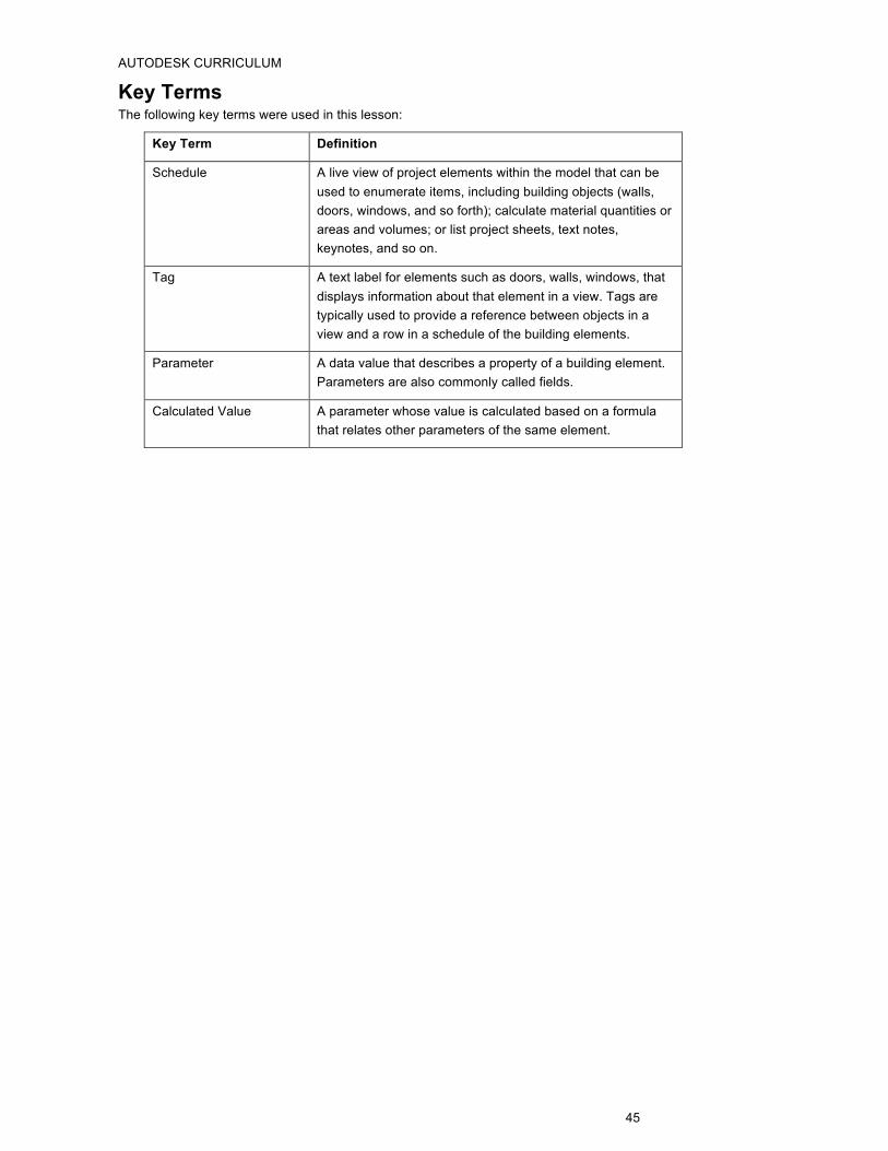
Key Terms The following key terms were used in this lesson:
Key Term Definition
Schedule A live view of project elements within the model that can be used to enumerate items, including building objects (walls, doors, windows, and so forth); calculate material quantities or areas and volumes; or list project sheets, text notes, keynotes, and so on.
Tag A text label for elements such as doors, walls, windows, that displays information about that element in a view. Tags are typically used to provide a reference between objects in a view and a row in a schedule of the building elements.
Parameter A data value that describes a property of a building element. Parameters are also commonly called fields.
Calculated Value A parameter whose value is calculated based on a formula that relates other parameters of the same element.