+ All Categories
Home > Documents > Bimbo Bakeries Albany, NY Bread - usscanman.com Reports/2019 Reports/Bimbo Bakeri… · BIMBO...

Bimbo Bakeries Albany, NY Bread - usscanman.com Reports/2019 Reports/Bimbo Bakeri… · BIMBO...

Date post: 07-Jul-2020
Category:
Upload: others
View: 16 times
Download: 0 times
Share this document with a friend
39
BIMBO BAKERIES USA BREAD PLANT ALBANY, NEW YORK August, 2019 Infrared Inspection Report© 2605 CHARTER OAK DRIVE, LITTLE ROCK, AR 72227 PHONE: 800-737-1787 & 501-228-5001 FAX: 501-228-5001 EMAIL: [email protected] Bimbo Bakeries USA 1 Prospect Road Albany, New York, 12206 Company Contact: Gustavo Calvo Project: 07200819
Transcript

BIMBO BAKERIES USA

BREAD PLANT

ALBANY,NEW YORK

August, 2019

Infrared Inspection Report©

2605 CHARTER OAK DRIVE, LITTLE ROCK, AR 72227PHONE: 800-737-1787 & 501-228-5001 FAX: 501-228-5001 EMAIL: [email protected]

Bimbo Bakeries USA1 Prospect RoadAlbany, New York, 12206Company Contact:Gustavo CalvoProject: 07200819

DISCLAIMERThis report and the recommendations contained in it are based upon conditions and practices observed and information madeavailable to United Spectrographics personnel. This report does not purport to list all hazards or faulty conditions. It is not in-tended to indicate that other hazards or faulty conditions do not exist. Severity ratings in the report are based on the criteriashown in this report and are intended as guidelines only. No responsibility is assumed for the control of the facility’s condition,maintenance practices or correction of conditions indicated herein.By issuing this report, neither United Spectrographics nor any of its employees makes any warranty, expressed or implied, con-cerning the contents of this report. Furthermore, neither United Spectrographics nor any of its employees shall be liable in anymanner (other than liability that may be expressed in any policy of insurance that may be issued by United Spectrographics) forpersonal injury or property damage or loss of any kind arising from or connected with this inspection or failure to inspect.

ORDER OF REPORT CONTENTS

1: Data To Facilitate Understanding &Utilizing Scan Report

2: Scan Results Overview & Action TakenForm

3: Identified Faulting Conditions,Information & Photographs

4: List Of Facility Equipment IdentifiedBy The Customer Representative &Notations Of Faulting Conditions Found

Utilizing Report Contents

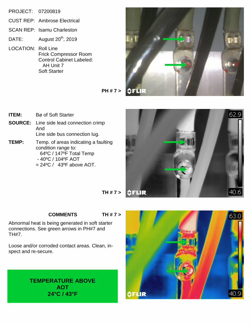
Included in this report are Photographs and Thermographs of problem areas found during our recent

Infrared Inspection of your facility.

Each problem area picture is accompanied by:

Date

Location Information

Temperature Calculations

Color-coded Temperature Intensity and/or Condition Significance Data

A Brief Comment Relating The Item In The Photograph To Its Corresponding

Thermograph

Suggested Corrective Recommendations.

In most cases, problems (faults) found will be listed according to the date and order that they were located,

rather then by significance or priority, as we feel that you and/or your personnel can best judge this,

keeping in mind circuit importance and thermograph intensity.

Thermal intensity is indicated by use of a color-coded data inserts that locate a fault‘s position on the

standard electrical failure curve. The color of the insert represents the temperature range of the hottest

item, or a portion of the item's circuitry, pointed out in the thermograph. The temperature ranges which the

colored inserts represent are grouped as follows:

INSERT Temperature Range

Red 70ºC/126ºF and higher above Ambient Operating Temp.

Orange 40ºC/72ºF to 69ºC/124ºF above Ambient Operating Temp.

Yellow 25ºC/45ºF to 39ºC/70ºF above Ambient Operating Temp.

Green *10ºC/18ºF to 24ºC/43ºF above Ambient Operating Temp.( * See page 4)

FAULTY EQUIPMONTHS MONTHS TO WEEKS WEEKS TO NOW

Determining Cost Effective Responses

Electrical equipment failures generally follow a standard mechanical/electrical failure curve. Dividing thefailure curve into temp. ranges and locating a problems position on the curve allows us to indicate theprobable time to its failure. Knowing a problems probable time to failure allows you to make a cost effectiveresponse to the problem areas that we locate.

Below is a depiction of the electrical fault failure curve with the thermal intensity ranges and thecolors that we assign to faults detailed in our reports.

Built In Trend Monitoring

When yearly scans are accomplished, report results allow you to trend monitor your electrical equipmentwithout having to cross reference previous report findings.

If a previous years problem is not repaired it will show up again in the current scan report and its currentintensity range indicates a current effective response.

YEARS

10ºC *18ºF

25ºC45ºF

40°C72ºF

70°C126ºF

AMBIENT TEMP

STANDARD ELECTRICAL FAULT FAILURE CURVE(Does Not Include Area In Blue)

DEVICETEMP

ISAMBIENT,

BUTDEVICE

ISEITHERFAULTY

ORUNSAFE.INTERMEDIATEMINOR SERIOUS CRITICAL

Defining Total Temperature and Ambient Operating Temperature AndExplanation For Their Use

Total Temperature:

Total Temperature = Ambient Operating Temperature + Fault temperature

Allows you, the customer, to evaluate possible damage to equipment.

Leads fail between 90ºC/194ºF and 110ºC/230ºPhenolic fails around 200ºC/392ºFTransformers and Motor Insulation failure temperature depends oninsulation class rating.Contacts start to fail around 130ºC/266ºF

Ambient Operating Temperature (AOT*) for Infrared Scanning Purposes:

Temperature within a device container (Box or Cabinet) that is not directly affected byfaulting component = Normal Equipment Operating Temperature Contained By Boxor Cabinet.

If there is no container (Example: Device mounted to a wall) it is the temperatureadjacent to the device not affected by the fault.

Allows you, the customer, to determine if device will operate at intended amperage.

Most switchgear is rated to operate at approximately 40ºC/104ºF (Industrial) to50ºC/122ºF (Marine)

If AOT is enough above normal rated temperature, either of the followingconditions can cause an unanticipated trip.

1. An intermittent high load.2. A minor (Green) or intermediate (Yellow) fault.

Report pages with photographs:

PH stands for Visible Light PhotographTH stands for Infrared Light Thermograph

*AOT stands for Ambient Operating Temperature

Both black & white and color infrared thermographs are presented to better depict thefault condition.

In addition to the corrective response time frame suggested below and the failure curve lo-cated on the previous page, you may want to consider using the militarystandard responses presented below.

Military Standard For Evaluating Faults Located In Electrical Equipment UtilizingTemperature Data Obtained With Infrared Imaging Equipment:

Temperatures rise above Ambient Operating Temperature:

*10ºC/18ºF to 24ºC/43ºF component failure unlikely, but corrective measures required at nextscheduled routine maintenance period or as scheduling permits. (Green Label)

25ºC/45ºF to 39ºC/70ºF component failure probable, unless corrected. (Yellow Label)

40ºC/72ºF to 69ºC/124ºF component failure almost certain, unless corrected.(Orange Label)

70ºC/126ºF and above component failure imminent. Immediately inform the person responsible forcontinued operation of equipment. (Red Label)

Note: United Spectrographics uses a Blue Label to indicate faults that require attention due toeither ambient temperature (Ex: Phase Not Operating), faulty equipment elements or unsafeconditions.

* Note: Temperature conditions below 10ºC/18ºF rise above AOT are not consideredsignificant enough to record and are usually not included in the reports unless the faulttemperature is being affected by a cooling medium such as oil or wind.

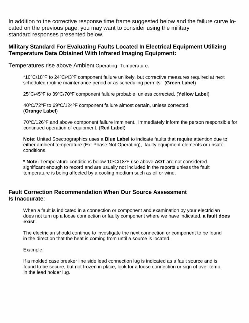
Fault Correction Recommendation When Our Source AssessmentIs Inaccurate:

When a fault is indicated in a connection or component and examination by your electriciandoes not turn up a loose connection or faulty component where we have indicated, a fault doesexist.

The electrician should continue to investigate the next connection or component to be foundin the direction that the heat is coming from until a source is located.

Example:

If a molded case breaker line side lead connection lug is indicated as a fault source and isfound to be secure, but not frozen in place, look for a loose connection or sign of over temp.in the lead holder lug.

SCAN RESULTS OVERVIEW

PROMPT ATTENTION ITEMS:

Because of:

1. The intensity or heat level indicated at the time of the scan.

2. Deterioration caused by excessive temperature not present at the time of the scan.

3. Physical condition irregularities observed at the time of the scan.

We recommend that the following faults be given prompt attention:

Faults: #1, #11*, #12*

Items With Asterisks Have High Total or Ambient Operating Temperatures.

United SpectrographicsAugust, 2019

SUMMARY OF FINDINGS

FAULTS BY CATEGORY NUMBER OF FAULTS FAULT NO./ITEM NO.

MINOR 8

2/46 4/3685/378 6/1997/205 8/101

9/108 10/249

INTERMEDIATE 1 3/368

SERIOUS 1 1/319

CRITICAL 211/28912/99

SERIOUS 0 0

Number of items located at facility: 441

Number of faults: 12

ffl!#itcetgographicsl!To : Christine Grimshaw

Maintenance System ManagerBimbo Bakeries USA3301 RIder Trail SouthEarth City, MO

As requested by United Spectrographics technician_Isamu Charleston

my signature below indicates that all faulting conditions found during the _21 st_/_Aug_/_2019_

inspection of the Bimbo Bakeries USA facility in _Albany,New York

were given to me or my designated representative in the "Bimbo Faults Found Form" and Iunderstand the location and severity of the faulting conditions found during the survey and theresponse needed to correct these faults.

I also understand that the final report will be sent to me within 2 weeks of the inspection and willalso be made available electronically to designated Bimbo corporate personnel.

PrintedNane_*` GL),i+iLS _ CL=~\Jo NU`€L..__

Tft[ex___ _ _ P\2_i £'v`g;i4 _e±:y-Date_21st_/_August_/_2019_

ACTION TAKENBimbo Bakeries USA Bread

Albany, New YorkAugust, 2019

Fault # Item # Category Repaired Monitor Date Name

1 319 Serious

2 46 Minor

3 368 Intermediate

4 368 Minor

5 378 Minor

6 199 Minor

7 205 Minor

8 101 Minor

9 108 Minor

10 249 Minor

11 289 Critical

12 99 Critical

PROJECT: 07200819

CUST REP: Ambrose Electrical

SCAN REP: Isamu Charleston

DATE: August 20th, 2019

LOCATION: White BreadCompressor RoomBox Labeled:

WB Compressor #3Fuse Disconnect

PH # 1 >

ITEM: Bø of Disconnect

SOURCE: Line side lead connection lug.

TEMP: Temp. of connection and lug is:94ºC / 201ºF Total Temp.

- 40ºC / 104ºF AOT= 54ºC / 97ºF above AOT.

TH # 1 >

COMMENTS

Abnormal heat is being generated in disconnectconnection. See orange arrows in PH#1 andTH#1.

Loose and/or corroded contact area. Clean, in-spect and re-secure serviceable components.

TEMPERATURE ABOVEAOT

54°C / 97°F

TH # 1 >

PROJECT: 07200819

CUST REP: Ambrose Electrical

SCAN REP: Isamu Charleston

DATE: August 20th, 2019

LOCATION: Sanitation HallwayBox Labeled:

Main Panel SP-4AFuse Disconnect

< PH # 2

ITEM: Cø of Disconnect

SOURCE: Line side lead connection lugAndLine & load side disconnect bladecontact area.

TEMP: Temp. of areas indicating a faultingcondition range to:

49ºC / 120ºF Total Temp.- 33ºC / 91ºF AOT

= 16ºC / 29ºF above AOT.

< TH # 2

COMMENTS

Abnormal heat is being generated in disconnectcomponents. See green arrows in PH#2 andTH#2.

Loose and/or corroded contact areas. Clean, in-spect and re-secure.

TEMPERATURE ABOVEAOT

16°C / 29°F

< TH # 2

PROJECT: 07200819

CUST REP: Ambrose Electrical

SCAN REP: Isamu Charleston

DATE: August 20th, 2019

LOCATION: White BreadMake-Up AreaUnlabeled Control Cabinet For:

WB Greaser #2 CPMotor Control

PH # 3 >

ITEM: Aø of Motor Control Contact Block

SOURCE: Line side lead connection lug.

TEMP: Temp. of connection and lug is:69ºC / 156ºF Total Temp.

- 37ºC / 97ºF AOT= 32ºC / 59ºF above AOT.

TH # 3 >

COMMENTS

Abnormal heat is being generated in motor con-trol connection. See yellow arrows in PH#3 andTH#3.

Loose and/or corroded contact area. Clean, in-spect and re-secure.

TEMPERATURE ABOVEAOT

32°C / 59°F

TH # 3 >

PROJECT: 07200819

CUST REP: Ambrose Electrical

SCAN REP: Isamu Charleston

DATE: August 20th, 2019

LOCATION: White BreadMake-Up AreaUnlabeled Control Cabinet For:

WB Greaser #2 CPMotor Control

< PH # 4

ITEM: Bø of Motor Control Overload Relay

SOURCE: Load side lead connection lug.

TEMP: Temp. of connection and lug is:53ºC / 127ºF Total Temp.

- 37ºC / 97ºF AOT= 16ºC / 30ºF above AOT.

< TH # 4

COMMENTS

Abnormal heat is being generated in motor con-trol connection. See green arrows in PH#4 andTH#4.

Loose and/or corroded contact area. Clean, in-spect and re-secure.

TEMPERATURE ABOVEAOT

16°C / 30°F

< TH # 4

PROJECT: 07200819

CUST REP: Ambrose Electrical

SCAN REP: Isamu Charleston

DATE: August 20th, 2019

LOCATION: White BreadOven AreaControl Cabinet Labeled:

Cascade System “O” & “D”Conveyors

Right Cabinet DoorMain Molded Case Breaker

PH # 5 >

ITEM: Bø of Case Breaker

SOURCE: Line side lead connection lug.

TEMP: Temp. of connection and lug is:54ºC / 129ºF Total Temp.

- 39ºC / 102ºF AOT= 15ºC / 27ºF above AOT.

TH # 5 >

COMMENTS

Abnormal heat is being generated in casebreaker connection. See green arrows in PH#5and TH#5.

Loose and/or corroded contact area. Clean, in-spect and re-secure.

TEMPERATURE ABOVEAOT

15°C / 27°F

TH # 5 >

PROJECT: 07200819

CUST REP: Ambrose Electrical

SCAN REP: Isamu Charleston

DATE: August 20th, 2019

LOCATION: Roll LineMain Switchgear RoomRolls DP-2 SwitchgearSection 1Right Side BreakersMolded Case Breaker Labeled:

DP-5

< PH # 6

ITEM: Middleø of Case Breaker

SOURCE: Load side lead connection lug.

TEMP: Temp. of connection and lug is:62ºC / 144ºF Total Temp.

- 39ºC / 102ºF AOT= 23ºC / 42ºF above AOT.

< TH # 6

COMMENTS

Abnormal heat is being generated in casebreaker connection. See green arrows in PH#6and TH#6.

Loose and/or corroded contact area. Clean, in-spect and re-secure.

TEMPERATURE ABOVEAOT

23°C / 42°F

< TH # 6

PROJECT: 07200819

CUST REP: Ambrose Electrical

SCAN REP: Isamu Charleston

DATE: August 20th, 2019

LOCATION: Roll LineFrick Compressor RoomControl Cabinet Labeled:

AH Unit 7Soft Starter

PH # 7 >

ITEM: Bø of Soft Starter

SOURCE: Line side lead connection crimpAndLine side bus connection lug.

TEMP: Temp. of areas indicating a faultingcondition range to:

64ºC / 147ºF Total Temp- 40ºC / 104ºF AOT

= 24ºC / 43ºF above AOT.

TH # 7 >

COMMENTS

Abnormal heat is being generated in soft starterconnections. See green arrows in PH#7 andTH#7.

Loose and/or corroded contact areas. Clean, in-spect and re-secure.

TEMPERATURE ABOVEAOT

24°C / 43°F

TH # 7 >

PROJECT: 07200819

CUST REP: Ambrose Electrical

SCAN REP: Isamu Charleston

DATE: August 20th, 2019

LOCATION: Variety LineMake-Up AreaBox Labeled:

Main Panel DFuse Disconnect

< PH # 8

ITEM: Bø & Cø Disconnect & Fuse Block

SOURCE: Disconnect: Line & load side discon-nect blade contact area.Fuse Block: Line side fuse bladeholder.

TEMP: Temp. of areas indicating a faultingcondition range to:

57ºC / 135ºF Total Temp.- 37ºC / 99ºF AOT

= 20ºC / 36ºF above AOT.

< TH # 8

COMMENTS

Abnormal heat is being generated in fuse discon-nect components. See green arrows in PH#8 andTH#8.

Loose and/or corroded contact areas. Clean, in-spect and re-secure.

TEMPERATURE ABOVEAOT

20°C / 36°F

< TH # 8

PROJECT: 07200819

CUST REP: Ambrose Electrical

SCAN REP: Isamu Charleston

DATE: August 20th, 2019

LOCATION: Variety LineMake-Up AreaControl Cabinet Labeled:

Panel P-2 Control PanelRight Cabinet DoorBottom Of CabinetMolded Case Breaker Labeled:

BKR133PH # 9 >

ITEM: Bø of Case Breaker

SOURCE: Load side lead connection lug.

TEMP: Temp. of connection and lug is:50ºC / 122ºF Total Temp

- 37ºC / 99ºF AOT= 13ºC / 23ºF above AOT.

TH # 9 >

COMMENTS

Abnormal heat is being generated in casebreaker connection. See green arrows in PH#9and TH#9.

Loose and/or corroded contact area. Clean, in-spect and re-secure.

TEMPERATURE ABOVEAOT

13°C / 23°F

TH # 9 >

PROJECT: 07200819

CUST REP: Ambrose Electrical

SCAN REP: Isamu Charleston

DATE: August 21st, 2019

LOCATION: Roll LineOven AreaBox Labeled:

AHU #3Combination Starter

< PH # 10

ITEM: Aø Fuse Block

SOURCE: Line side fuse clip.

TEMP: Temp. of fuse clip is:61ºC / 142ºF Total Temp.

- 43ºC / 109ºF AOT= 18ºC / 33ºF above AOT.

Note: AOT is high.

< TH # 10

COMMENTS

Abnormal heat is being generated in fuse blockcomponent. See green arrows in PH#10 andTH#10.

Loose and/or corroded contact area. Clean, in-spect and re-secure.

TEMPERATURE ABOVEAOT

18°C / 33°F

< TH # 10

PROJECT: 07200819

CUST REP: Ambrose Electrical

SCAN REP: Isamu Charleston

DATE: August 21st, 2019

LOCATION: Roll LinePackaging AreaControl Cabinet Labeled:

Roll Depanner Control PanelMain Fuse Disconnect

PH # 11 >

ITEM: Bø Fuse Block

SOURCE: Line side fuse clip.

TEMP: Temp. of fuse clip is:122ºC / 252ºF Total Temp

- 52ºC / 126ºF AOT= 70ºC / 126ºF above AOT.

Note: AOT is high.

TH # 11 >

COMMENTS

Abnormal heat is being generated in fuse blockcomponent. See red arrows in PH#11 andTH#11.

Loose and/or corroded contact area. Clean, in-spect and re-secure serviceable components.

TEMPERATURE ABOVEAOT

70°C / 126°F

TH # 11 >

PROJECT: 07200819

CUST REP: Ambrose Electrical

SCAN REP: Isamu Charleston

DATE: August 21st, 2019

LOCATION: Variety BreadMake-Up AreaBox Labeled:

Cooler Air HandlerFuse Disconnect

< PH # 12

ITEM: Aø, Bø, & Cø Fuse Block

SOURCE: Line side fuse blade holder.

TEMP: Temp. of blade holders range to:138ºC / 280ºF Total Temp

- 42ºC / 108ºF AOT= 96ºC / 172ºF above AOT.

Note: AOT is high.

< TH # 12

COMMENTS

Abnormal heat is being generated in fuse blockcomponents. See red arrows in PH#12 andTH#12.

Loose and/or corroded contact areas. Clean, in-spect and re-secure serviceable components.

TEMPERATURE ABOVEAOT

96°C / 192°F

< TH # 12

No. Equipment Operating VisuallyInspected

Fault #

MAINTENANCE SHOP

1 127-15—480/277 Volt Distribution Panel X

2 128-15—208/120 Volt Distribution Panel X

PARTS ROOM

3 Maintenance Shop Parts Panel—208/120 Volt DistributionPanel

X

OUTSIDE MAINTENANCE SHOP

4 129-15—208/120 Volt Distribution Panel X

5 130-15—480/277 Volt Distribution Panel X

6 Overhead 45 kVA Sorgel 3ø Transformer (Not In Service)

7 Flour Scaling CP—Control Cabinet X

8 Patent Reclaim CP—Control Cabinet X

9 Scissor Jack—Fuse Disconnect X

10 VB Truck Power CP—Control Cabinet X

11 Vega—PLC Cabinet X

12 WB/VB Bulk Flour CP—Control Cabinet X

13 OUTSIDE OF UPSTAIRS SCALING ROOM

14 P3-CP—Control Cabinet X

WAREHOUSE

15 106-15 / Warehouse Office Panel—208/120 Volt DistributionPanel

X

16 WHS Panel—208/120 Volt Distribution Panel X

17 WHS Transformer—45 kVA Sorgel 3ø Transformer X

18 101-06 Blower—Combination Starter X

19 Main For WHS Transformer—Fuse Disconnect X
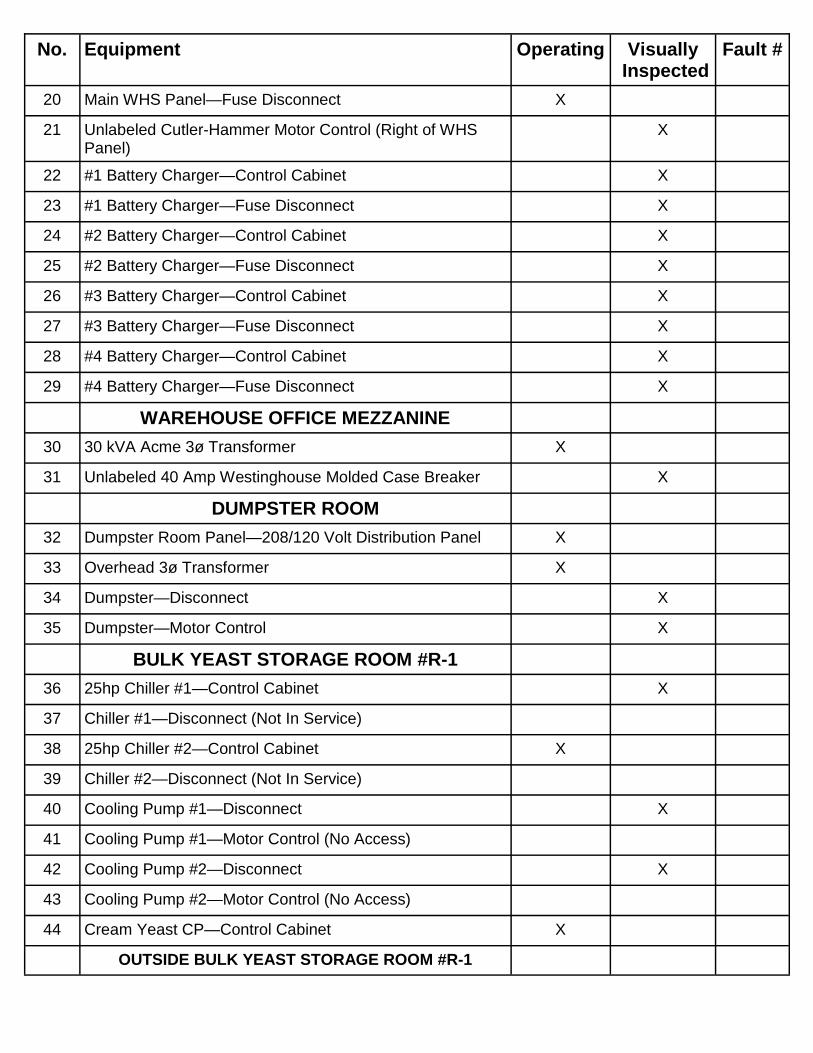
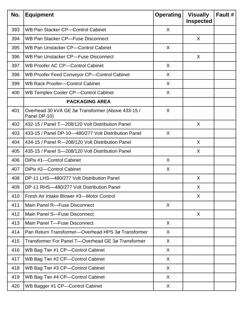
AREA/EQUIPMENT LIST

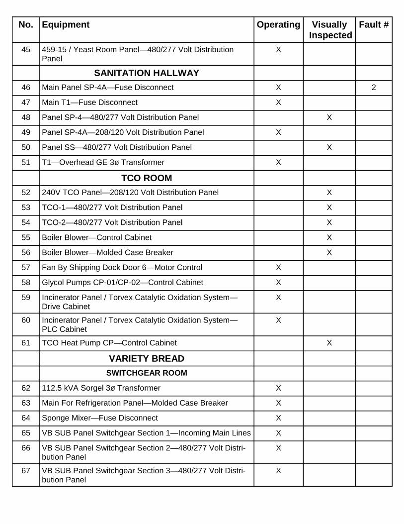
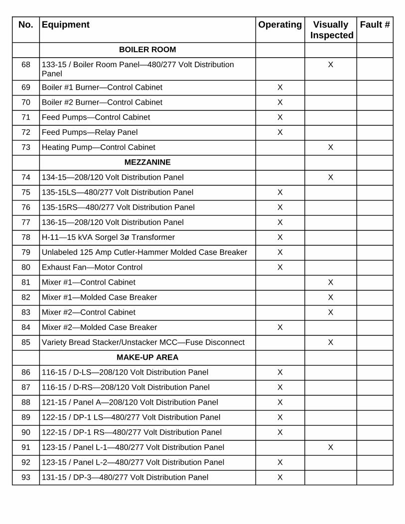
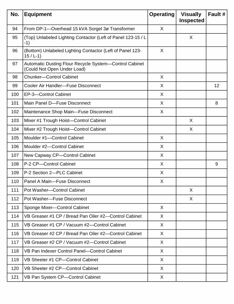
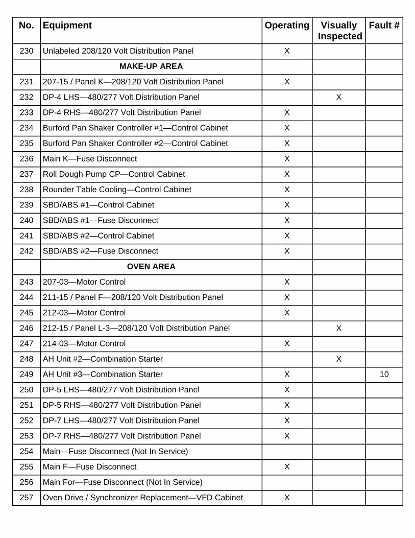
Following is a list of the electrical equipment located at the Bimbo Bakeries USA Bread Plant, Albany,New York, facility and data relating to its operating condition at the time the scan was performed.

NOTE: Items noted as visually inspected were not operational or show no visibleload at the time of the inspection.

No. Equipment Operating VisuallyInspected

Fault #

20 Main WHS Panel—Fuse Disconnect X

21 Unlabeled Cutler-Hammer Motor Control (Right of WHSPanel)

X

22 #1 Battery Charger—Control Cabinet X

23 #1 Battery Charger—Fuse Disconnect X

24 #2 Battery Charger—Control Cabinet X

25 #2 Battery Charger—Fuse Disconnect X

26 #3 Battery Charger—Control Cabinet X

27 #3 Battery Charger—Fuse Disconnect X

28 #4 Battery Charger—Control Cabinet X

29 #4 Battery Charger—Fuse Disconnect X

WAREHOUSE OFFICE MEZZANINE

30 30 kVA Acme 3ø Transformer X

31 Unlabeled 40 Amp Westinghouse Molded Case Breaker X

DUMPSTER ROOM

32 Dumpster Room Panel—208/120 Volt Distribution Panel X

33 Overhead 3ø Transformer X

34 Dumpster—Disconnect X

35 Dumpster—Motor Control X

BULK YEAST STORAGE ROOM #R-1

36 25hp Chiller #1—Control Cabinet X

37 Chiller #1—Disconnect (Not In Service)

38 25hp Chiller #2—Control Cabinet X

39 Chiller #2—Disconnect (Not In Service)

40 Cooling Pump #1—Disconnect X

41 Cooling Pump #1—Motor Control (No Access)

42 Cooling Pump #2—Disconnect X

43 Cooling Pump #2—Motor Control (No Access)

44 Cream Yeast CP—Control Cabinet X

OUTSIDE BULK YEAST STORAGE ROOM #R-1

No. Equipment Operating VisuallyInspected

Fault #

45 459-15 / Yeast Room Panel—480/277 Volt DistributionPanel

X

SANITATION HALLWAY

46 Main Panel SP-4A—Fuse Disconnect X 2

47 Main T1—Fuse Disconnect X

48 Panel SP-4—480/277 Volt Distribution Panel X

49 Panel SP-4A—208/120 Volt Distribution Panel X

50 Panel SS—480/277 Volt Distribution Panel X

51 T1—Overhead GE 3ø Transformer X

TCO ROOM

52 240V TCO Panel—208/120 Volt Distribution Panel X

53 TCO-1—480/277 Volt Distribution Panel X

54 TCO-2—480/277 Volt Distribution Panel X

55 Boiler Blower—Control Cabinet X

56 Boiler Blower—Molded Case Breaker X

57 Fan By Shipping Dock Door 6—Motor Control X

58 Glycol Pumps CP-01/CP-02—Control Cabinet X

59 Incinerator Panel / Torvex Catalytic Oxidation System—Drive Cabinet

X

60 Incinerator Panel / Torvex Catalytic Oxidation System—PLC Cabinet

X

61 TCO Heat Pump CP—Control Cabinet X

VARIETY BREAD

SWITCHGEAR ROOM

62 112.5 kVA Sorgel 3ø Transformer X

63 Main For Refrigeration Panel—Molded Case Breaker X

64 Sponge Mixer—Fuse Disconnect X

65 VB SUB Panel Switchgear Section 1—Incoming Main Lines X

66 VB SUB Panel Switchgear Section 2—480/277 Volt Distri-bution Panel

X

67 VB SUB Panel Switchgear Section 3—480/277 Volt Distri-bution Panel

X

No. Equipment Operating VisuallyInspected

Fault #

BOILER ROOM

68 133-15 / Boiler Room Panel—480/277 Volt DistributionPanel

X

69 Boiler #1 Burner—Control Cabinet X

70 Boiler #2 Burner—Control Cabinet X

71 Feed Pumps—Control Cabinet X

72 Feed Pumps—Relay Panel X

73 Heating Pump—Control Cabinet X

MEZZANINE

74 134-15—208/120 Volt Distribution Panel X

75 135-15LS—480/277 Volt Distribution Panel X

76 135-15RS—480/277 Volt Distribution Panel X

77 136-15—208/120 Volt Distribution Panel X

78 H-11—15 kVA Sorgel 3ø Transformer X

79 Unlabeled 125 Amp Cutler-Hammer Molded Case Breaker X

80 Exhaust Fan—Motor Control X

81 Mixer #1—Control Cabinet X

82 Mixer #1—Molded Case Breaker X

83 Mixer #2—Control Cabinet X

84 Mixer #2—Molded Case Breaker X

85 Variety Bread Stacker/Unstacker MCC—Fuse Disconnect X

MAKE-UP AREA

86 116-15 / D-LS—208/120 Volt Distribution Panel X

87 116-15 / D-RS—208/120 Volt Distribution Panel X

88 121-15 / Panel A—208/120 Volt Distribution Panel X

89 122-15 / DP-1 LS—480/277 Volt Distribution Panel X

90 122-15 / DP-1 RS—480/277 Volt Distribution Panel X

91 123-15 / Panel L-1—480/277 Volt Distribution Panel X

92 123-15 / Panel L-2—480/277 Volt Distribution Panel X

93 131-15 / DP-3—480/277 Volt Distribution Panel X

No. Equipment Operating VisuallyInspected

Fault #

94 From DP-1—Overhead 15 kVA Sorgel 3ø Transformer X

95 (Top) Unlabeled Lighting Contactor (Left of Panel 123-15 / L-1)

X

96 (Bottom) Unlabeled Lighting Contactor (Left of Panel 123-15 / L-1)

X

97 Automatic Dusting Flour Recycle System—Control Cabinet(Could Not Open Under Load)

98 Chunker—Control Cabinet X

99 Cooler Air Handler—Fuse Disconnect X 12

100 EP-3—Control Cabinet X

101 Main Panel D—Fuse Disconnect X 8

102 Maintenance Shop Main—Fuse Disconnect X

103 Mixer #1 Trough Hoist—Control Cabinet X

104 Mixer #2 Trough Hoist—Control Cabinet X

105 Moulder #1—Control Cabinet X

106 Moulder #2—Control Cabinet X

107 New Capway CP—Control Cabinet X

108 P-2 CP—Control Cabinet X 9

109 P-2 Section 2—PLC Cabinet X

110 Panel A Main—Fuse Disconnect X

111 Pot Washer—Control Cabinet X

112 Pot Washer—Fuse Disconnect X

113 Sponge Mixer—Control Cabinet X

114 VB Greaser #1 CP / Bread Pan Oiler #2—Control Cabinet X

115 VB Greaser #1 CP / Vacuum #2—Control Cabinet X

116 VB Greaser #2 CP / Bread Pan Oiler #2—Control Cabinet X

117 VB Greaser #2 CP / Vacuum #2—Control Cabinet X

118 VB Pan Indexer Control Panel—Control Cabinet X

119 VB Sheeter #1 CP—Control Cabinet X

120 VB Sheeter #2 CP—Control Cabinet X

121 VB Pan System CP—Control Cabinet X

No. Equipment Operating VisuallyInspected

Fault #

122 VB Pan System CP—Disconnect X

123 VBP Dough Saver Electrical Panel—Control Cabinet X

OVEN AREA

124 DP-2 LS—480/277 Volt Distribution Panel X

125 DP-2 RS—480/277 Volt Distribution Panel X

126 132-15 / Panel B—208/120 Volt Distribution Panel X

127 Unlabeled (Feed PP1) 200 Amp Square D Fuse Disconnect X

128 Main For Oven Panel—Molded Case Breaker X

129 Main Panel B—Fuse Disconnect X

130 VB 5KVA Proofer—Control Cabinet X

131 VB Conveyor PD1/PD3 P1/P8—Control Cabinet X

132 VB Fresh Air—Motor Control X

133 VB Oven CP—Control Cabinet X

134 VB Oven CP Main Disconnect—Fuse Disconnect X

135 VB Oven CP Lighting Disconnect—Control Cabinet X

136 VB Pan Cleaner—Control Cabinet (Locked)

137 VB Pan Cleaner—Power Supply X

138 VB Pan Stacker—Control Cabinet X

139 VB Pan Stacker—Disconnect X

140 VB Pan Unstacker—Control Cabinet X

141 VB Pan Unstacker—Disconnect X

142 VB Seeder CP—Control Cabinet X

143 VB Slitter CP / L-O A1 #112-01 Proofer—Control Cabinet X

144 VB Vacuum Panel—Control Cabinet X

PACKAGING AREA

145 114-15 / PP-2 Slicer/Bagger—208/120 Volt DistributionPanel

X

146 115-15—208/120 Volt Distribution Panel X

147 138-15 / Panel C—208/120 Volt Distribution Panel X

148 Pattern Maker PP—480/277 Volt Distribution Panel X

No. Equipment Operating VisuallyInspected

Fault #

149 PP1-LS—480/277 Volt Distribution Panel X

150 PP1-RS—480/277 Volt Distribution Panel X

151 Overhead 15 kVA Sorgel 3ø Transformer X

152 (Left) Unlabeled GE Combination Starter X

153 (Right) Unlabeled GE Combination Starter X

154 DiPix—Control Cabinet X

155 EP-2 CP / Slicer Feed System—Control Cabinet X

156 Exhaust Fan—Motor Control X

157 (Left) Unlabeled (Exhaust Fan) Allen-Bradley Motor Control X

158 (Right) Unlabeled (Exhaust Fan) Allen-Bradley Motor Con-trol

X

159 Panel C Main—Fuse Disconnect X

160 Pattern Maker #1 CPa—Control Cabinet X

161 Pattern Maker #2 CPa—Control Cabinet X

162 Pattern Maker #3 CPa—Control Cabinet X

163 Pattern Maker #4 CPa—Control Cabinet X

164 Swamp Cooler—Control Cabinet X

165 Tray Stacker #1 CPa—Control Cabinet X

166 Tray Stacker #1 CPb—Control Cabinet X

167 Tray Stacker #2 CPa—Control Cabinet X

168 Tray Stacker #2 CPb—Control Cabinet X

169 Tray Stacker #3 CPa—Control Cabinet X

170 Tray Stacker #3 CPb—Control Cabinet X

171 Tray Stacker #4 CPa—Control Cabinet X

172 Tray Stacker #4 CPb—Control Cabinet X

173 VB 7KVA Cooler CP / Templex Cooler—Control Cabinet X

174 VB Bagger #1 CP—Control Cabinet X

175 VB Bagger #2 CP—Control Cabinet X

176 VB Bagger #3 CP—Control Cabinet X

177 VB Bagger #4 CP—Control Cabinet X

No. Equipment Operating VisuallyInspected

Fault #

178 VB Bag Tier #1 CP—Control Cabinet X

179 VB Bag Tier #2 CP—Control Cabinet X

180 VB Bag Tier #3 CP—Control Cabinet X

181 VB Bag Tier #4 CP—Control Cabinet X

182 VB C&D Line / Rated KVA 6—Control Cabinet X

183 VB Depanner CP—Control Cabinet X

184 VB Slicer #1 CP—Control Cabinet X

185 VB Slicer #2 CP—Control Cabinet X

186 VB Slicer #3 CP—Control Cabinet X

187 VB Slicer #4 CP—Control Cabinet X

ROLL LINE

MAIN SWITCHGEAR ROOM

188 30 kVA Cutler-Hammer 3ø Transformer X

189 208-15 LS—208/120 Volt Distribution Panel X

190 208-15 RS—208/120 Volt Distribution Panel X

191 B-DP-4 RHS—208/120 Volt Distribution Panel X

192 DP4 Control Relay—Contactor X

193 Main For Panels 208-15—Fuse Disconnect X

194 Main For Transformer—Fuse Disconnect X

195 Main Sub Lighting Contactor—Lighting Control Panel X

196 Main Utility Bus Switchgear Section 1—Incoming Lines X

197 Main Utility Bus Switchgear Section 2—Rolls DP-1 CircuitBreaker & White Bread Circuit Breaker

X

198 Main Utility Bus Switchgear Section 3—Variety Bread Cir-cuit Breaker & Rolls DP-2 Circuit Breaker

X

199 Rolls DP-2 Switchgear Section 1—480/277 Volt DistributionPanel

X 6

200 Rolls DP-2 Switchgear Section 2—Incoming Lines X

201 Room Exhaust—Motor Control X

FRICK COMPRESSOR ROOM

202 Mixer Cooling System—Relay Panel X

No. Equipment Operating VisuallyInspected

Fault #

203 AH Unit 1—Soft Starter X

204 AH Unit 3 / RC-3 (Frick) CP—Soft Starter X

205 AH Unit 7—Soft Starter X 7

UPSTAIRS ELECTRICAL ROOM #R-4

206 30 kVA GE 3ø Transformer X

207 1hp Chiller Pump—Fuse Disconnect X

208 1hp Chiller Pump—Motor Control X

209 2hp Chiller Pump—Fuse Disconnect X

210 3hp Condenser—Combination Starter X

211 Condenser Pump #1—Combination Starter X

212 VFD Condenser #1—VFD X

213 Condenser Pump #2—Combination Starter X

214 VFD Condenser #2—VFD X

215 Exhaust Fan—Fuse Disconnect X

216 VFD Exhaust Fan—VFD X

217 Glycol Pump #1—VFD X

218 Glycol Pump #2—Motor Control X

219 Main For T-5—Fuse Disconnect X

220 Panel K—Disconnect X

221 Panel PP-4—480/277 Volt Distribution Panel X

222 Panel T-5—208/120 Volt Distribution Panel X

223 Peerless Mixer—Control Cabinet X

224 Peerless Mixer—Molded Case Breaker X

225 Process Water Chill System—Relay Panel X

226 Roll Dough Pump—Control Cabinet X

227 Transformer 5—45 kVA Cutler-Hammer 3ø Transformer X

228 Water Chiller Compressor—Fuse Disconnect (Not In Ser-vice)

229 Unlabeled Square D Motor Control (Below Water ChillerCompressor Fuse Disconnect)

X

HUDDLE ROOM

No. Equipment Operating VisuallyInspected

Fault #

230 Unlabeled 208/120 Volt Distribution Panel X

MAKE-UP AREA

231 207-15 / Panel K—208/120 Volt Distribution Panel X

232 DP-4 LHS—480/277 Volt Distribution Panel X

233 DP-4 RHS—480/277 Volt Distribution Panel X

234 Burford Pan Shaker Controller #1—Control Cabinet X

235 Burford Pan Shaker Controller #2—Control Cabinet X

236 Main K—Fuse Disconnect X

237 Roll Dough Pump CP—Control Cabinet X

238 Rounder Table Cooling—Control Cabinet X

239 SBD/ABS #1—Control Cabinet X

240 SBD/ABS #1—Fuse Disconnect X

241 SBD/ABS #2—Control Cabinet X

242 SBD/ABS #2—Fuse Disconnect X

OVEN AREA

243 207-03—Motor Control X

244 211-15 / Panel F—208/120 Volt Distribution Panel X

245 212-03—Motor Control X

246 212-15 / Panel L-3—208/120 Volt Distribution Panel X

247 214-03—Motor Control X

248 AH Unit #2—Combination Starter X

249 AH Unit #3—Combination Starter X 10

250 DP-5 LHS—480/277 Volt Distribution Panel X

251 DP-5 RHS—480/277 Volt Distribution Panel X

252 DP-7 LHS—480/277 Volt Distribution Panel X

253 DP-7 RHS—480/277 Volt Distribution Panel X

254 Main—Fuse Disconnect (Not In Service)

255 Main F—Fuse Disconnect X

256 Main For—Fuse Disconnect (Not In Service)

257 Oven Drive / Synchronizer Replacement—VFD Cabinet X

No. Equipment Operating VisuallyInspected

Fault #

258 Panel H—208/120 Volt Distribution Panel X

259 Roll 970 Oven CP—Control Cabinet X

260 Roll Conveyor CP—Control Cabinet X

261 Roll Dusting Flour Vacuum CP—Control Cabinet X

262 Roll Fresh Air CP—Motor Control X

263 Roll P/Line CP—Control Cabinet X

264 Roll Pan Cleaner CP—Control Cabinet X

265 Roll Pan Return CP—Control Cabinet X

266 Roll Pan Stacker CP—Control Cabinet X

267 Roll Pan Unstacker CP—Control Cabinet X

268 Roll Pulver T-Transfer CP—Control Cabinet X

269 Roll Proofer CP—Control Cabinet X

270 Roll Proofer AC CP—Control Cabinet X

271 Transformer T-4—Overhead 30 kVA Square D 3ø Trans-former

X

PACKAGING AREA

272 203-03—Motor Control X

273 206-03—Motor Control X

274 219-15 / Panel L-4—480/277 Volt Distribution Panel X

275 Above Tray Fans—Motor Control X

276 AH Unit #1—Combination Starter X

277 Bag Tier #1 CP—Control Cabinet X

278 Bag Tier #2 CP—Control Cabinet X

279 Basket System EP-3 / EP-3 CP—Control Cabinet X

280 Basket System EP-4 / EP-4 CP—Control Cabinet X

281 DP-1A—480/277 Volt Distribution Panel X

282 DP-6 LHS—480/277 Volt Distribution Panel X

283 DP-6 RHS—480/277 Volt Distribution Panel X

284 Main For T-3—Fuse Disconnect (Not In Service)

285 Main G—Fuse Disconnect (Not In Service)

No. Equipment Operating VisuallyInspected

Fault #

286 Metal Detector—Control Cabinet X

287 Panel G—208/120 Volt Distribution Panel X

288 Roll Cooler CP—Control Cabinet X

289 Roll Depanner CP—Control Cabinet X 11

290 Roll DP-1 Switchgear Section 1—Main Breaker 1600 AmpCircuit Breaker

X

291 Roll DP-1 Switchgear Section 2—480/277 Volt DistributionPanel

X

292 Roll Loader #1 CP—Control Cabinet X

293 Roll Loader #2 CP—Control Cabinet X

294 Roll Stacker #1 CPa—Control Cabinet X

295 Roll Stacker #1 CPb—Control Cabinet X

296 Roll Stacker #2 CPa—Control Cabinet (Broken Release)

297 Roll Stacker #2 CPb—Control Cabinet X

298 Roll UBE Bagger #1 CP—Control Cabinet X

299 Roll UBE Bagger #2 CP—Control Cabinet X

300 Transformer For Panel G—Overhead 30 kVA Square D 3øTransformer

X

301 Tray Wash CP—Control Cabinet X

302 US 3A CP / Bottom-Out Tray Unstacker-A—Control Cabinet X

303 US 3B CP / Bottom-Out Tray Unstacker-B—Control Cabinet X

304 Wireless Power Panel / PP-1—208/120 Volt DistributionPanel

X

305 Wireless Power Transformer—Overhead 45 kVA GE 3øTransformer

X

WHITE BREAD

COMPRESSOR ROOM

306 409-15 / Panel PP-5—480/277 Volt Distribution Panel X

307 Air Dryer—Control Cabinet X

308 Bulk Bin Blower Disconnect—Disconnect X

309 EF/6—Motor Control X

310 EF/7—Motor Control X

No. Equipment Operating VisuallyInspected

Fault #

311 Panel CP-A—208/120 Volt Distribution Panel X

312 Panel CP-B—208/120 Volt Distribution Panel X

313 Panel CP-C—480/277 Volt Distribution Panel X

314 Panel PP-6—480/277 Volt Distribution Panel X

315 Transformer From PP-5—Overhead 15 kVA GE 3ø Trans-former

X

316 WB Compressor #1—Control Cabinet X

317 WB Compressor #2—Control Cabinet X

318 WB Compressor #3—Control Cabinet (Plexiglas) X

319 WB Compressor #3—Fuse Disconnect X 1

320 White Bread Spencer Vacuum—Motor Control X

OLD BOILER ROOM

321 Boiler Room Panel—480/277 Volt Distribution Panel X

322 Condensate Pumps—Control Cabinet X

323 Fire Protection Panel—Control Cabinet X

324 Main—Fuse Disconnect X

325 Panel N—480/277 Volt Distribution Panel X

SWITCHGEAR ROOM #WB-5

326 WB Main—Main Breaker 1600 Amp Circuit Breaker &480/277 Volt Distribution Panel

X

327 WB Main Bus Switchgear Section 1—Incoming Lines X

328 WB Main Bus Switchgear Section 2—480/277 Volt Distribu-tion Panel

X

329 WB Main Bus Switchgear Section 3—480/277 Volt Distribu-tion Panel

X

MAKE-UP AREA

330 Overhead GE 3ø Transformer X

331 Unlabeled AMF (Make-Up Area) Control Cabinet X

332 Unlabeled Eaton Motor Control (Below Main EF1) X

333 Bulk Bin Blower CP—PLC Cabinet X

334 Chunker—Control Cabinet X

335 Dough Pump—Control Cabinet X

No. Equipment Operating VisuallyInspected

Fault #

336 Dough Pump—Molded Case Breaker X

337 Dough Saver Control—Control Cabinet X

338 Exhaust Fan Contactor For EF and EF1—Contactor X

339 Flour Transfer CP—Control Cabinet (Not In Service)

340 Main EF-1—Fuse Disconnect X

341 Main Panel M—Fuse Disconnect X

342 Main Panel P—Fuse Disconnect X

343 Main Panel PH—Fuse Disconnect X

344 Mixer #1—Control Cabinet X

345 Mixer #2—Control Cabinet X

346 Motor Starter Panel (Flour Silos)—Control Cabinet X

347 Motor Starter Panel (Flour Silos)—Molded Case Breaker X

348 Moulder #1—Control Cabinet X

349 Moulder #2—Control Cabinet X

350 Panel EF—480/277 Volt Distribution Panel X

351 Panel EF-1—208/120 Volt Distribution Panel X

352 Panel DP-8—480/277 Volt Distribution Panel X

353 Panel DP-9—480/277 Volt Distribution Panel X

354 Panel L-5—480/277 Volt Distribution Panel X

355 Panel M—208/120 Volt Distribution Panel X

356 Panel P—208/120 Volt Distribution Panel X

357 Panel PH—208/120 Volt Distribution Panel X

358 Panel R.P. 1—480/277 Volt Distribution Panel X

359 Panel 3100 (Rapido Jet #1)—Control Cabinet (Not In Ser-vice)

360 Panel 3100 (Rapido Jet #1)—Fuse Disconnect (Not In Ser-vice)

361 Panel 3200 (Rapido Jet #2)—Control Cabinet X

362 Panel 3200 (Rapido Jet #2)—Fuse Disconnect X

363 Shick Panel 401 CP—Control Cabinet X

364 Vega—PLC Cabinet X

No. Equipment Operating VisuallyInspected

Fault #

365 Water Delivery System Panel P02—PLC Cabinet X

366 WB Capway CP—Control Cabinet X

367 WB Greaser #1 CP—Control Cabinet X

368 WB Greaser #2 CP—Control Cabinet X 3, 4

369 WB Greaser Reclaimer #1 CP—Control Cabinet X

370 WB Greaser Reclaimer #2 CP—Control Cabinet X

371 WB Pan Indexer Inverter Control Panel—Control Cabinet X

372 WB Sheeter #1 CP—Control Cabinet X

373 WB Sheeter #2 CP—Control Cabinet X

374 WB Truck Power—Junction Box X

OVEN AREA

375 (Left) Unlabeled Allen-Bradley (Cooler Fan) Motor Control X

376 (Right) Unlabeled Allen-Bradley (Cooler Fan) Motor Control X

377 427-15 / Panel L-6—480/277 Volt Distribution Panel X

378 Cascade System “O”&”D” Conveyors—Control Cabinet X 5

379 Fresh Air Intake Blower #2—Control Cabinet X

380 Lid Line LS CP—Control Cabinet X

381 Lid Line RS CP—Control Cabinet X

382 Lid Return Conveyors CP—Control Cabinet X

383 MAC Dust Collector—Disconnect X

384 Pan Return Conveying System CP—Control Cabinet X

385 Triple-T Transfer Conveyors—Control Cabinet X

386 WB Depanner CP—Control Cabinet X

387 WB Hot Bread Conveyors—Control Cabinet X

388 WB Oven CP—Control Cabinet (Locked)

389 WB Oven CP Main Disconnect—Fuse Disconnect X

390 WB Oven CP Lighting Disconnect—Power Supply X

391 WB Pan Cleaner CP—Control Cabinet X

392 WB Pan Return Conveyor CP—Control Cabinet (Not In Ser-vice)

No. Equipment Operating VisuallyInspected

Fault #

393 WB Pan Stacker CP—Control Cabinet X

394 WB Pan Stacker CP—Fuse Disconnect X

395 WB Pan Unstacker CP—Control Cabinet X

396 WB Pan Unstacker CP—Fuse Disconnect X

397 WB Proofer AC CP—Control Cabinet X

398 WB Proofer Feed Conveyor CP—Control Cabinet X

399 WB Rack Proofer—Control Cabinet X

400 WB Templex Cooler CP—Control Cabinet X

PACKAGING AREA

401 Overhead 30 kVA GE 3ø Transformer (Above 433-15 /Panel DP-10)

X

402 432-15 / Panel T—208/120 Volt Distribution Panel X

403 433-15 / Panel DP-10—480/277 Volt Distribution Panel X

404 434-15 / Panel R—208/120 Volt Distribution Panel X

405 435-15 / Panel S—208/120 Volt Distribution Panel X

406 DiPix #1—Control Cabinet X

407 DiPix #2—Control Cabinet X

408 DP-11 LHS—480/277 Volt Distribution Panel X

409 DP-11 RHS—480/277 Volt Distribution Panel X

410 Fresh Air Intake Blower #3—Motor Control X

411 Main Panel R—Fuse Disconnect X

412 Main Panel S—Fuse Disconnect X

413 Main Panel T—Fuse Disconnect X

414 Pan Return Transformer—Overhead HPS 3ø Transformer X

415 Transformer For Panel T—Overhead GE 3ø Transformer X

416 WB Bag Tier #1 CP—Control Cabinet X

417 WB Bag Tier #2 CP—Control Cabinet X

418 WB Bag Tier #3 CP—Control Cabinet X

419 WB Bag Tier #4 CP—Control Cabinet X

420 WB Bagger #1 CP—Control Cabinet X

No. Equipment Operating VisuallyInspected

Fault #

421 WB Bagger #2 CP—Control Cabinet X

422 WB Bagger #3 CP—Control Cabinet X

423 WB Bagger #4 CP—Control Cabinet X

424 WB Loader #1 CP—Control Cabinet X

425 WB Loader #2 CP—Control Cabinet X

426 WB Loader #3 CP—Control Cabinet X

427 WB Loader #4 CP—Control Cabinet X

428 WB Over-Wrapper #4 CP—Control Cabinet X

429 WB Slicer #1 CP—Control Cabinet X

430 WB Slicer #2 CP—Control Cabinet X

431 WB Slicer #3 CP—Control Cabinet X

432 WB Slicer #4 CP—Control Cabinet X

433 WB Slicer Feeder System—Control Cabinet X

434 WB Stacker #1 CPa—Control Cabinet X

435 WB Stacker #1 CPb—Control Cabinet X

436 WB Stacker #2 CPa—Control Cabinet X

437 WB Stacker #2 CPb—Control Cabinet X

438 WB Stacker #3 CPa—Control Cabinet X

439 WB Stacker #3 CPb—Control Cabinet X

440 WB Stacker #4 CPa—Control Cabinet X

441 WB Stacker #4 CPb—Control Cabinet X


Recommended