11/18/14 1 Binary Phase Shift Keying (BPSK) In BPSK, the symbol mapping table encodes bits (b n ) 1 and 0 to transmission symbols (a n ) 1 and –1, respectively Every T b seconds the modulator transmits one of the two carrier bursts that corresponds to the information bit being a 1 or 0 Binary 1: Binary 0: The resultant BPSK signal can be expressed as x(t) contains only the in-phase component I(t); Q(t) is zero 1 () cos(2 ), 0 c c b st A ft t T π = ≤ ≤ ( ) () ( ) { } 2 () / cos 2 , 1 1 c n b b c n n t t A t nT T ft π ∞ = −∞ = Π − ∈ = − ∑ 14444244443 I x a a A 2 () cos(2 ) cos(2 ) c c c c s t A ft A ft π π π = + = −
Transcript
11/18/14 1
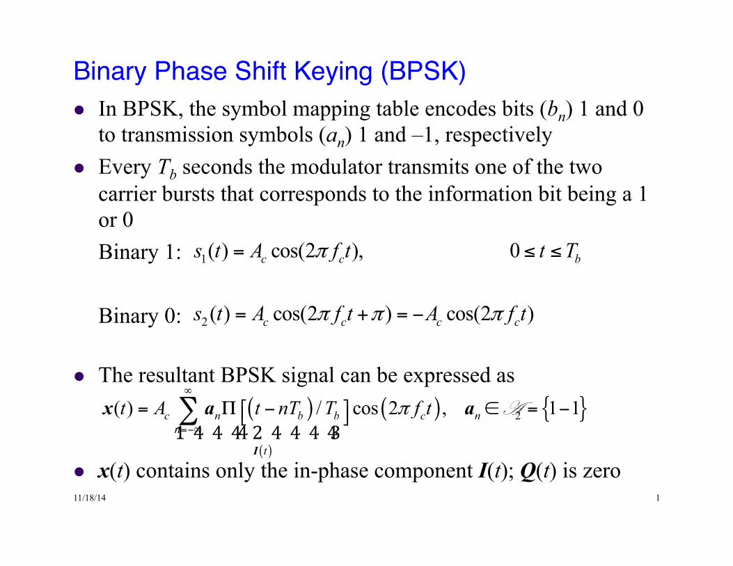
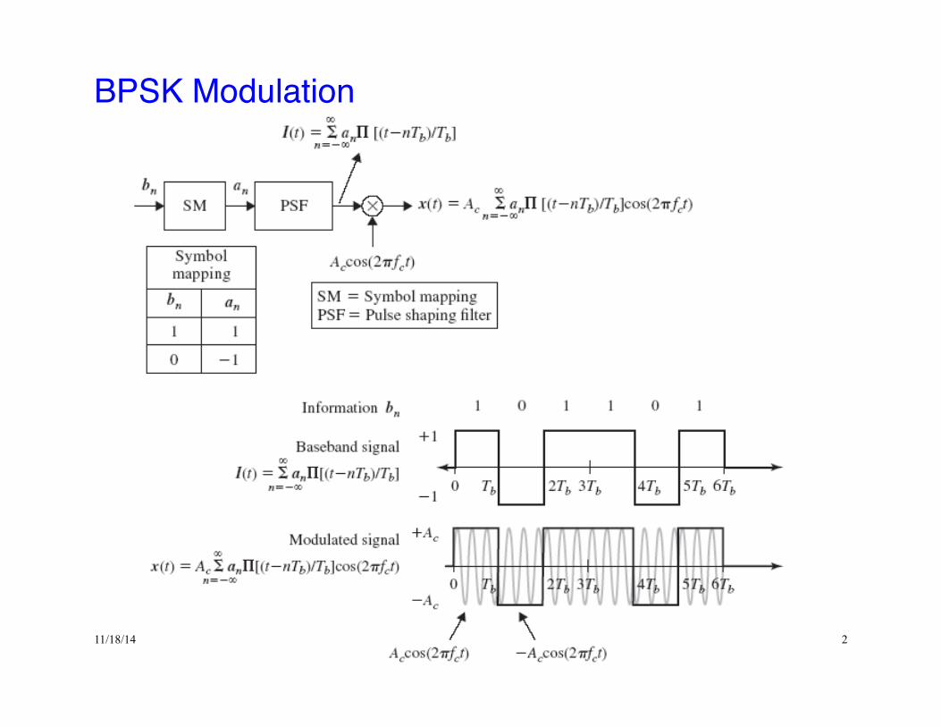
Binary Phase Shift Keying (BPSK) !l In BPSK, the symbol mapping table encodes bits (bn) 1 and 0
to transmission symbols (an) 1 and –1, respectively l Every Tb seconds the modulator transmits one of the two
carrier bursts that corresponds to the information bit being a 1 or 0
Binary 1: Binary 0:
l The resultant BPSK signal can be expressed as
l x(t) contains only the in-phase component I(t); Q(t) is zero
1( ) cos(2 ), 0c c bs t A f t t Tπ= ≤ ≤
( )
( )
( ) { }2( ) / cos 2 , 1 1c n b b c nn
t
t A t nT T f tπ∞
=−∞
⎡ ⎤= Π − ∈ = −⎣ ⎦∑1 4 4 44 2 4 4 4 43
I
x a a A
2 ( ) cos(2 ) cos(2 )c c c cs t A f t A f tπ π π= + = −
11/18/14 2
BPSK Modulation!
11/18/14 3
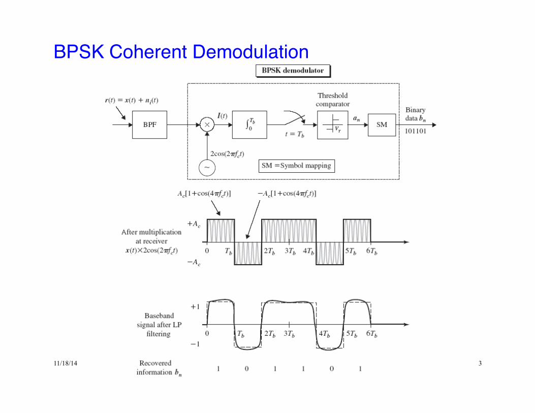
BPSK Coherent Demodulation!
11/18/14 4
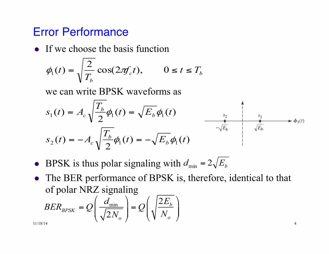
Error Performance!l If we choose the basis function
we can write BPSK waveforms as
l BPSK is thus polar signaling with l The BER performance of BPSK is, therefore, identical to that
of polar NRZ signaling
bcb
TttfT
t ≤≤= 0),2cos(2)(1 πφ
)()(2
)(
)()(2
)(
112
111
tEtTAts
tEtTAts
bb
c
bb
c
φφ
φφ
−=−=
==
bEd 2min =
min 22
bBPSK
oo
EdBER Q QNN
⎛ ⎞ ⎛ ⎞= =⎜ ⎟ ⎜ ⎟⎜ ⎟⎜ ⎟ ⎝ ⎠⎝ ⎠
11/18/14 5
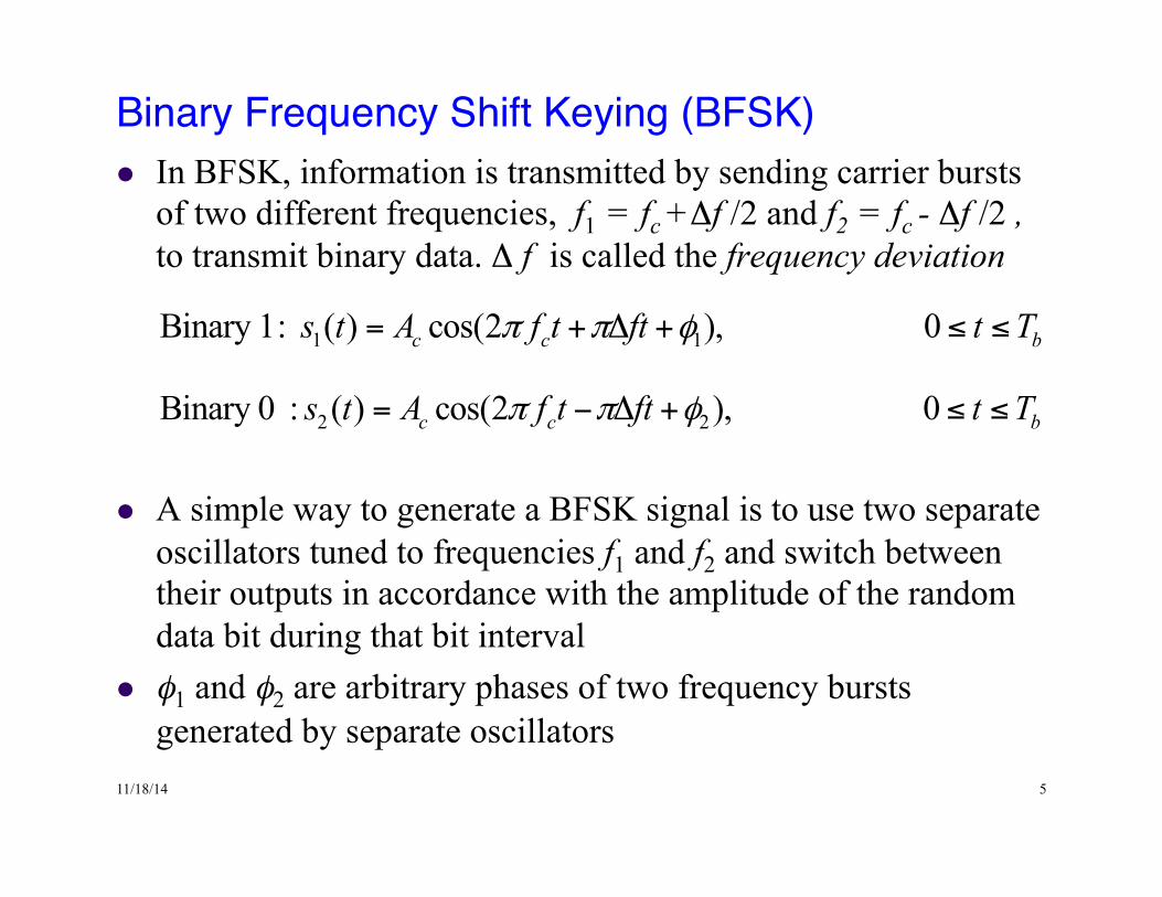
Binary Frequency Shift Keying (BFSK)!l In BFSK, information is transmitted by sending carrier bursts
of two different frequencies, f1 = fc +Δf /2 and f2 = fc - Δf /2 , to transmit binary data. Δ f is called the frequency deviation
l A simple way to generate a BFSK signal is to use two separate oscillators tuned to frequencies f1 and f2 and switch between their outputs in accordance with the amplitude of the random data bit during that bit interval
l φ1 and φ2 are arbitrary phases of two frequency bursts generated by separate oscillators
1 1Binary 1: ( ) cos(2 ), 0c c bs t A f t ft t Tπ π φ= + Δ + ≤ ≤
2 2Binary 0 : ( ) cos(2 ), 0c c bs t A f t ft t Tπ π φ= − Δ + ≤ ≤
11/18/14 6
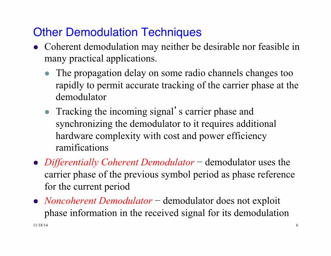
Other Demodulation Techniques!l Coherent demodulation may neither be desirable nor feasible in
many practical applications. l The propagation delay on some radio channels changes too
rapidly to permit accurate tracking of the carrier phase at the demodulator
l Tracking the incoming signal’s carrier phase and synchronizing the demodulator to it requires additional hardware complexity with cost and power efficiency ramifications
l Differentially Coherent Demodulator − demodulator uses the carrier phase of the previous symbol period as phase reference for the current period
l Noncoherent Demodulator − demodulator does not exploit phase information in the received signal for its demodulation
11/18/14 7
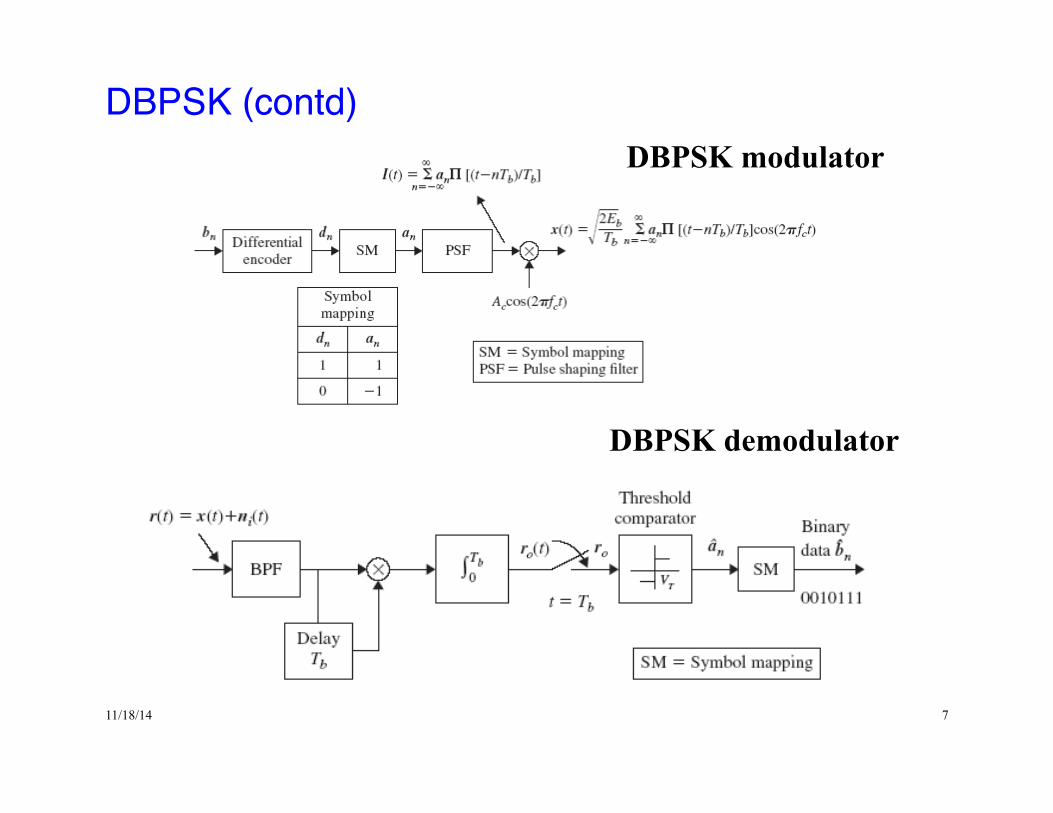
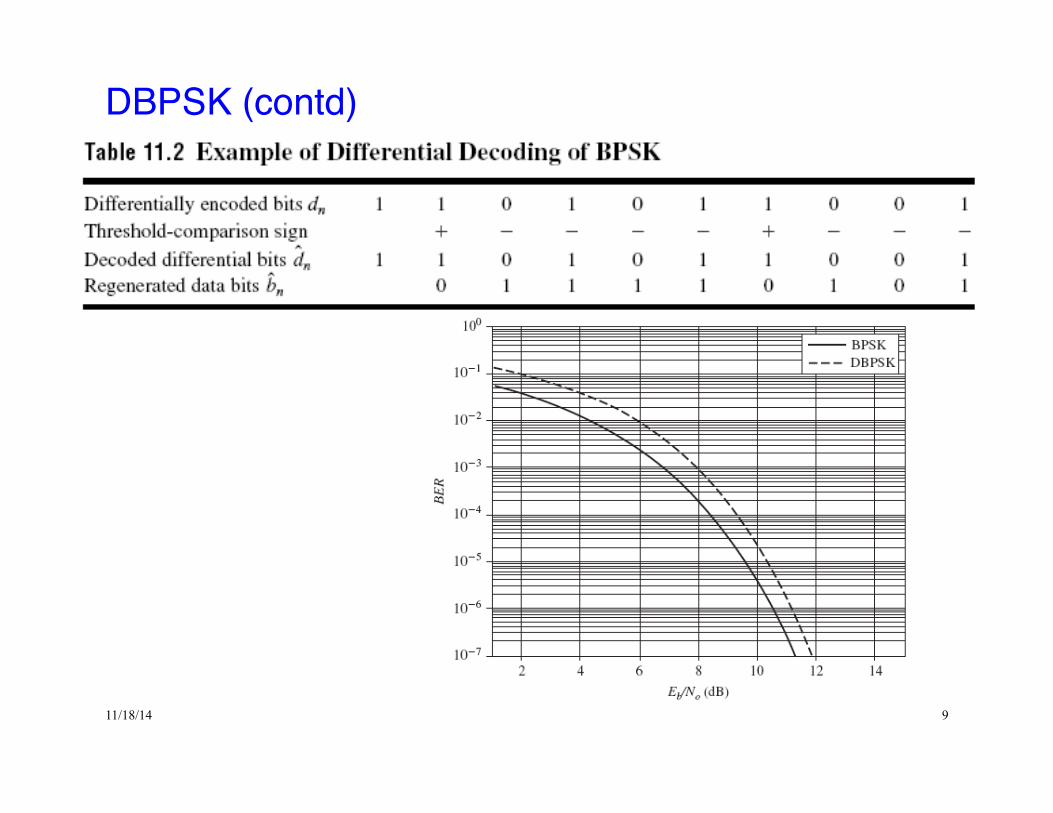
DBPSK (contd)!DBPSK modulator
DBPSK demodulator
11/18/14 8
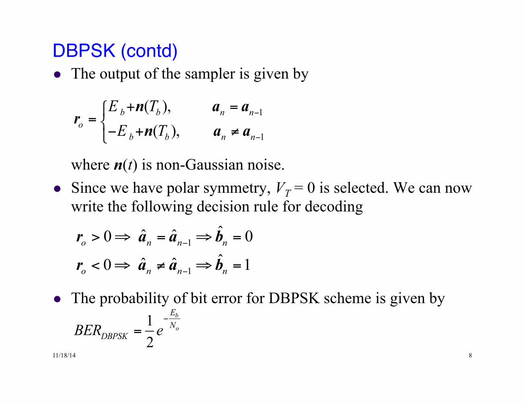
DBPSK (contd)!l The output of the sampler is given by
where n(t) is non-Gaussian noise. l Since we have polar symmetry, VT = 0 is selected. We can now
write the following decision rule for decoding
l The probability of bit error for DBPSK scheme is given by
1
1
ˆˆ ˆ0 0ˆˆ ˆ0 1
o n n n
o n n n
−
−
> ⇒ = ⇒ =
< ⇒ ≠ ⇒ =
r a a b
r a a b
1
1
( ), ( ),
b b n no
b b n n
E TE T
−
−
+ =⎧= ⎨
− + ≠⎩
n a ar
n a a
12
b
o
EN
DBPSKBER e−
=
11/18/14 9
DBPSK (contd)!
11/18/14 10
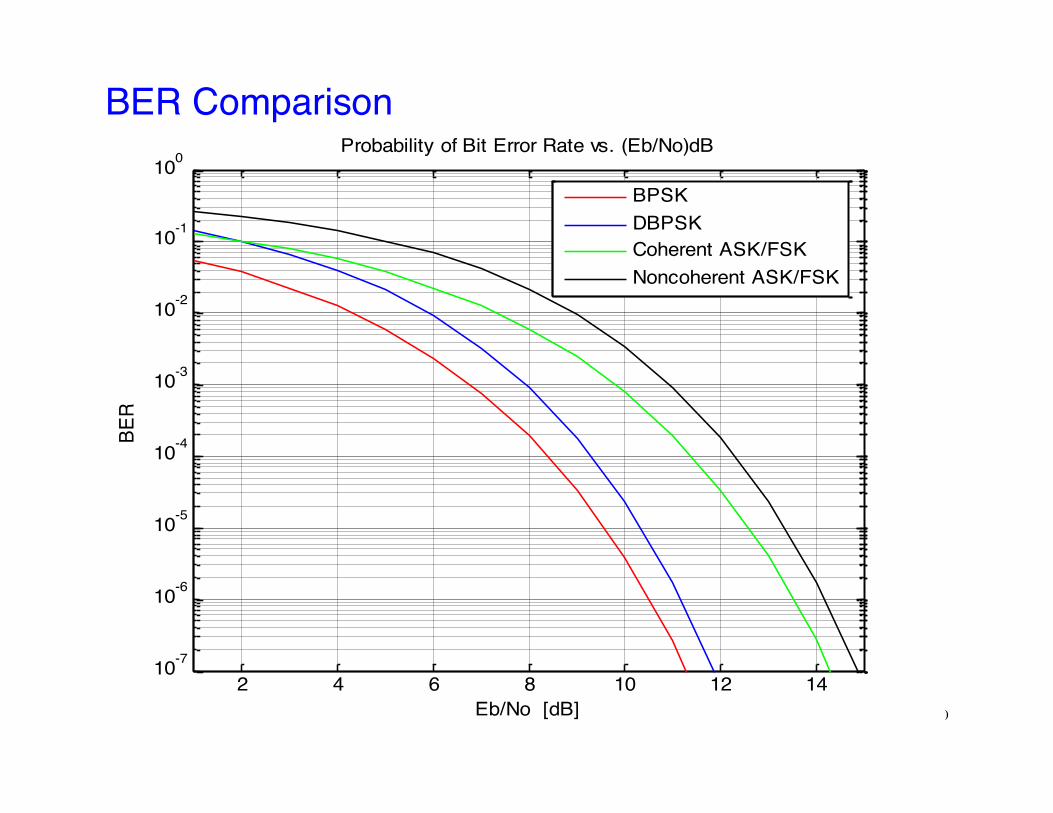
BER Comparison!
2 4 6 8 10 12 1410-7
10-6
10-5
10-4
10-3
10-2
10-1
100Probability of Bit Error Rate vs. (Eb/No)dB
Eb/No [dB]
BER
BPSKDBPSKCoherent ASK/FSKNoncoherent ASK/FSK
11/18/14 11
Quadrature Modulation Schemes!l In BPSK the phase of the carrier burst is shifted 0 or 180
degrees every pulse or symbol interval depending upon the information sequence. Thus each modulated carrier pulse transmits 1 bit of information
l If, on the other hand, the modulation scheme can use phase shifts of 45, 135, 225, or 315 degrees, each modulated carrier pulse transmits 2 bits of information. This technique is called Quadrature Phase Shift Keying (QPSK) l Using QPSK, we can double the data rate over the same
channel bandwidth. l QPSK is one of the modulation methods in the family known
as Quadrature modulation schemes which are widely used, including in cellular and cable modem applications
11/18/14 12
Quadrature Modulation Schemes (contd)!l Suppose an information source generates M-ary symbols at a
rate of D symbols/second ⇒ T = 1/D l The symbol stream is split into 2 sequences that consist of
odd and even symbols, say, and , respectively l Let modulate in-phase carrier Accos(2π fc t) every T
seconds to produce the signal
l This signal is identical to the BPSK signal if is polar binary symbol sequence
l Similarly, let modulate the quadrature carrier Acsin(2π fc t) every T seconds to produce the signal
Ina
Qna
In M∈a A
( ) ( ) ( )cos 2 ( )cos 2Ic n c c cn
A v t nT f t A t f tπ π∞
=−∞
− =∑ a I
( ) ( ) ( )sin 2 ( )sin 2Qc n c c cn
A w t nT f t A t f tπ π∞
=−∞
− =∑ a Q
Qn M∈a A
Ina
11/18/14 13
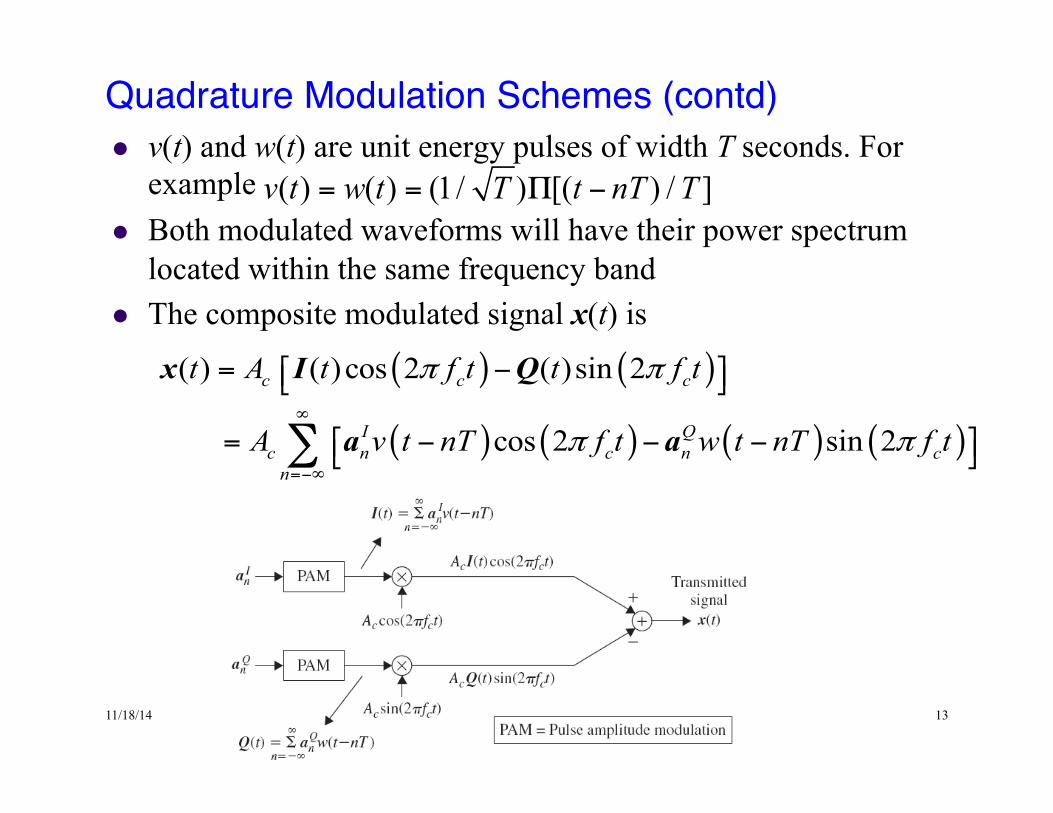
Quadrature Modulation Schemes (contd)!l v(t) and w(t) are unit energy pulses of width T seconds. For
example l Both modulated waveforms will have their power spectrum
located within the same frequency band l The composite modulated signal x(t) is
( ) ( )
( ) ( ) ( ) ( )
( ) ( )cos 2 ( )sin 2
cos 2 sin 2
c c c
I Qc n c n cn
t A t f t t f t
A v t nT f t w t nT f t
π π
π π∞
=−∞
= −⎡ ⎤⎣ ⎦
⎡ ⎤= − − −⎣ ⎦∑
x I Q
a a
( ) ( ) (1/ ) [( ) / ]v t w t T t nT T= = Π −
11/18/14 14
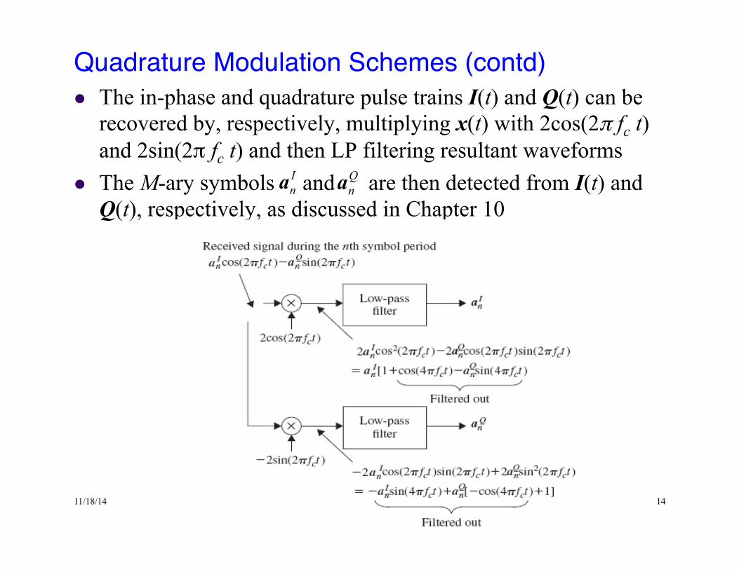
Quadrature Modulation Schemes (contd)!l The in-phase and quadrature pulse trains I(t) and Q(t) can be
recovered by, respectively, multiplying x(t) with 2cos(2π fc t) and 2sin(2π fc t) and then LP filtering resultant waveforms
l The M-ary symbols and are then detected from I(t) and Q(t), respectively, as discussed in Chapter 10
Ina
Qna
11/18/14 15
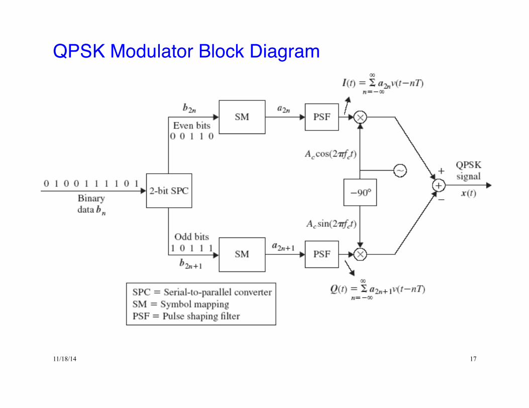
Quaternary Phase Shift Keying (QPSK)!l QPSK is the most common form of phase-shift keying. By
using phase shifts of 45, 135, 225, or 315 degrees, each modulated carrier pulse transmits 2 bits of information
l QPSK is a quadrature modulation scheme: each orthogonal carrier is modulated by a statistically independent polar NRZ symbol sequence
l The block diagram of a QPSK modulator is shown in Figure l Binary data arriving at rate Rb is split by a serial to parallel
converter into two data streams, one containing even bits (b2n) and other odd bits (b2n+1)
l The symbol mapping tables in the upper and lower branches of the modulator encode even and odd bits into polar transmission symbols a2n and a2n+1 , respectively
11/18/14 16
QPSK Modulator!l The output of the pulse shaping filter in the upper branch is a
binary polar NRZ pulse train I(t) that modulates the in-phase carrier
l Similarly, a binary polar NRZ pulse train Q(t) generated by the pulse shaping filter in the lower branch modulates the quadrature carrier
l The QPSK signal x(t) is now obtained by adding the in-phase and quadrature components
( ) ( )
( )
( )
2
2 1
( ) ( )cos 2 ( )sin 2
where
( )
( )
c c c
nn
nn
t A t f t t f t
t v t nT
t v t nT
π π
∞
=−∞
∞
+=−∞
⎡ ⎤= −⎣ ⎦
= −
= −
∑
∑
x I Q
I a
Q a
( )cos 2c cA f tπ
( )sin 2c cA f tπ
11/18/14 17
QPSK Modulator Block Diagram !
11/18/14 18
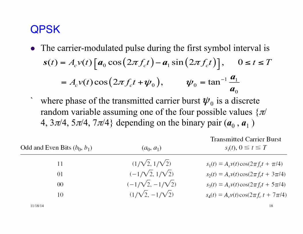
QPSK!l The carrier-modulated pulse during the first symbol interval is
` where phase of the transmitted carrier burst is a discrete
random variable assuming one of the four possible values {π/4, 3π/4, 5π/4, 7π/4} depending on the binary pair (a0 , a1 )
( ) ( )
( )
0 1
1 10 0
0
( ) ( ) cos 2 sin 2 , 0
( )cos 2 , tan
c c c
c c
t A v t f t f t t T
A v t f t
π π
π −
⎡ ⎤= − ≤ ≤⎣ ⎦
= + =
s a a
aa
ψ ψ
03 5 7, , ,
4 4 4 4π π π π⎧ ⎫∈⎨ ⎬⎩ ⎭
ψ
0ψ
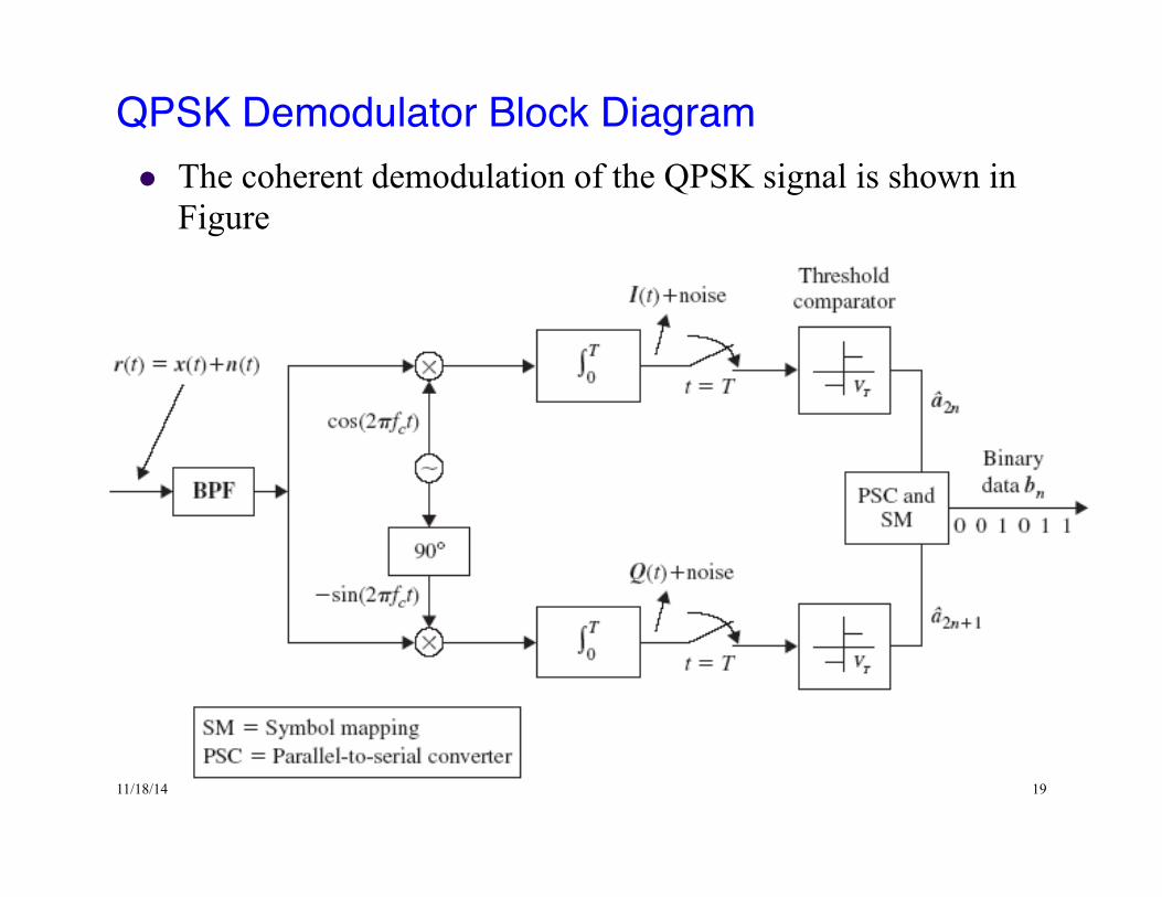
11/18/14 19
QPSK Demodulator Block Diagram!l The coherent demodulation of the QPSK signal is shown in
Figure
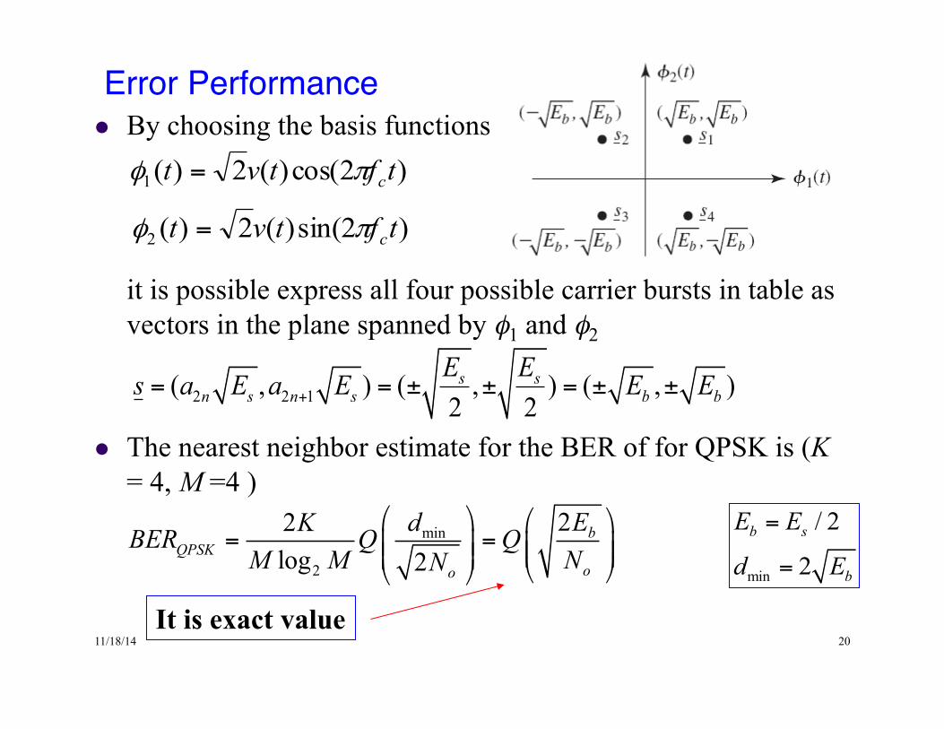
11/18/14 20
Error Performance!l By choosing the basis functions
it is possible express all four possible carrier bursts in table as vectors in the plane spanned by φ1 and φ2
l The nearest neighbor estimate for the BER of for QPSK is (K = 4, M =4 )
)2cos()(2)(1 tftvt cπφ =
)2sin()(2)(2 tftvt cπφ =
2 2 1( , ) ( , ) ( , )2 2s s
n s n s b bE Es a E a E E E+= = ± ± = ± ±
min
2
22log 2
bQPSK
oo
EdKBER Q QM M NN
⎛ ⎞ ⎛ ⎞= =⎜ ⎟ ⎜ ⎟⎜ ⎟⎜ ⎟ ⎝ ⎠⎝ ⎠
It is exact value
min
/ 2
2b s
b
E E
d E
=
=
11/18/14 21
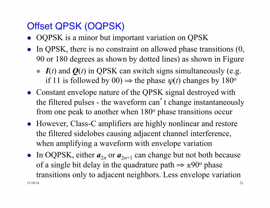
Offset QPSK (OQPSK)!l OQPSK is a minor but important variation on QPSK l In QPSK, there is no constraint on allowed phase transitions (0,
90 or 180 degrees as shown by dotted lines) as shown in Figure l I(t) and Q(t) in QPSK can switch signs simultaneously (e.g.
if 11 is followed by 00) ⇒ the phase ψ(t) changes by 180o l Constant envelope nature of the QPSK signal destroyed with
the filtered pulses - the waveform can’t change instantaneously from one peak to another when 180o phase transitions occur
l However, Class-C amplifiers are highly nonlinear and restore the filtered sidelobes causing adjacent channel interference, when amplifying a waveform with envelope variation
l In OQPSK, either a2n or a2n+1 can change but not both because of a single bit delay in the quadrature path ⇒ ±90o phase transitions only to adjacent neighbors. Less envelope variation
11/18/14 22
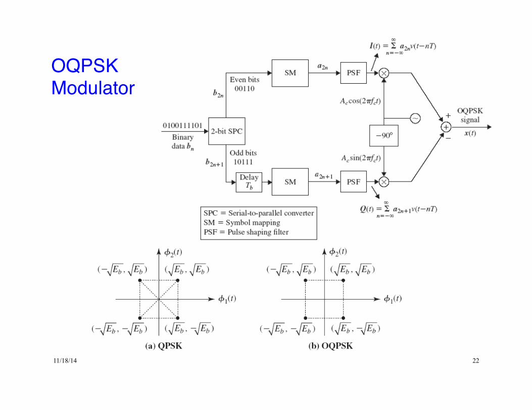
OQPSKModulator!
11/18/14 23
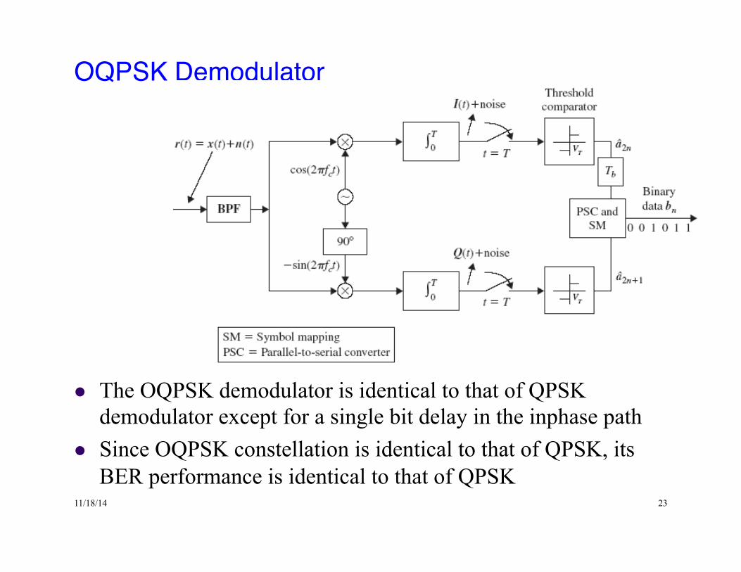
OQPSK Demodulator !
l The OQPSK demodulator is identical to that of QPSK demodulator except for a single bit delay in the inphase path
l Since OQPSK constellation is identical to that of QPSK, its BER performance is identical to that of QPSK
11/18/14 24
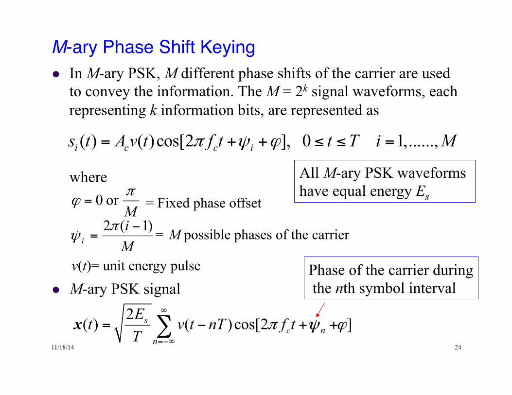
M-ary Phase Shift Keying !l In M-ary PSK, M different phase shifts of the carrier are used
to convey the information. The M = 2k signal waveforms, each representing k information bits, are represented as
where
l M-ary PSK signal
( ) ( )cos[2 ], 0 1,......,i c c is t A v t f t t T i Mπ ψ ϕ= + + ≤ ≤ =
Mi
i)1(2 −
=π
ψ
0 orMπ
ϕ =
= M possible phases of the carrier
= Fixed phase offset
v(t)= unit energy pulse
2( ) ( )cos[2 ]sc n
n
Et v t nT f tT
π ϕ∞
=−∞
= − + +∑x ψ
All M-ary PSK waveforms have equal energy Es
Phase of the carrier during the nth symbol interval
11/18/14 25
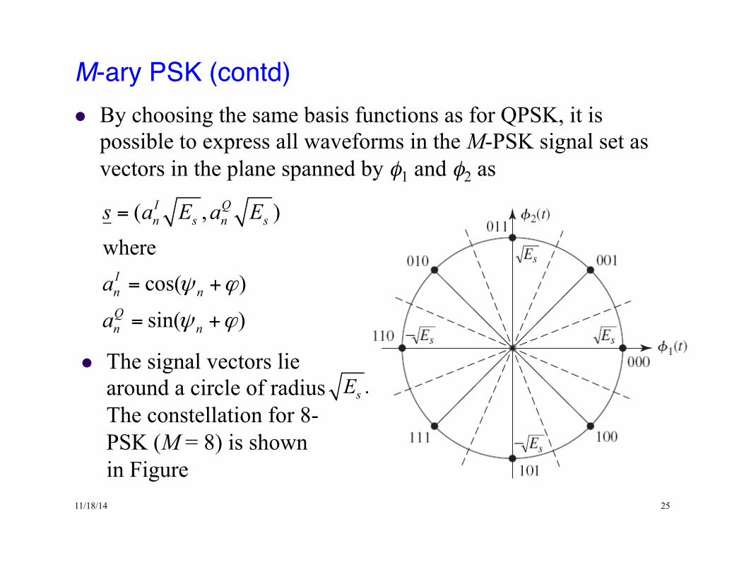
M-ary PSK (contd)!l By choosing the same basis functions as for QPSK, it is
possible to express all waveforms in the M-PSK signal set as vectors in the plane spanned by φ1 and φ2 as
( , )where
cos( )
sin( )
I Qn s n s
In nQn n
s a E a E
a
a
ψ ϕ
ψ ϕ
=
= +
= +
l The signal vectors lie around a circle of radius The constellation for 8-PSK (M = 8) is shown in Figure
.sE
11/18/14 26
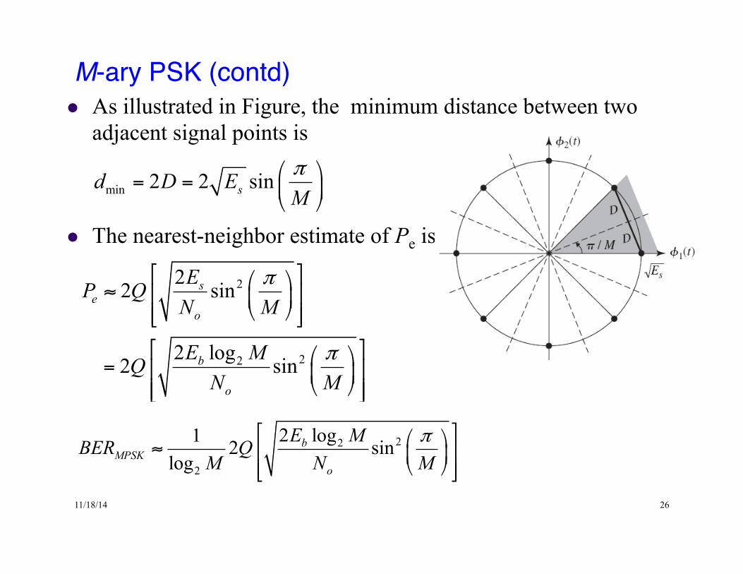
M-ary PSK (contd)!l As illustrated in Figure, the minimum distance between two
adjacent signal points is
l The nearest-neighbor estimate of Pe is
and the factor 2K/M in (4.23) is 2. This is a fairly tight bound
l The additional energy required for M-ary PSK compared to BPSK is