21
Biomechanical Guidelines For Headgear Application ---- GISELA I. CONTASTI, DDS, HARRY L. LEGAN, DDS
Biomechanical Guidelines For Headgear Application
----GISELA I. CONTASTI, DDS, HARRY L. LEGAN,
DDS

The efficient use of the headgear requires a sound knowledge of basic biomechanics. Understanding how to control the direction and magnitude of the forces produced by various headgear designs is paramount in achieving desirable clinical results. Decreasing the patient's length of treatment and improving the treatment results would be only two of the benefits derived from applying well-planned force systems. To aid the clinician, a method of analyzing force systems produced in the anterior-posterior and vertical planes will be presented.
Mechanical ModelFor diagrammatic purposes, the headgear is applied to the maxillary first molar. The center of resistance (CR) is that point of a constrained body through which a single force will cause translation of that body2. The CR is located about four-tenths of the distance apically from the height of the alveolar bone, or approximately at the trifurcation of the first molar roots. When the line of force (LF) is applied through the CR no tipping will occur. For practical purposes, the CR does not change for a given object such as a tooth. However, varying the application of the LF will change the way the tooth moves and, therefore, the center of rotation (CRot)4.
The inner bow of the headgear is placed into the molar buccal tubes parallel to the occlusal plane so that it lies comfortably between the lips. The outer bow is infinitely adjustable short, medium, long, up, down, etc. The assembly may be regarded as rigid, although we know that elastic deformation takes place when the headgear is activated.
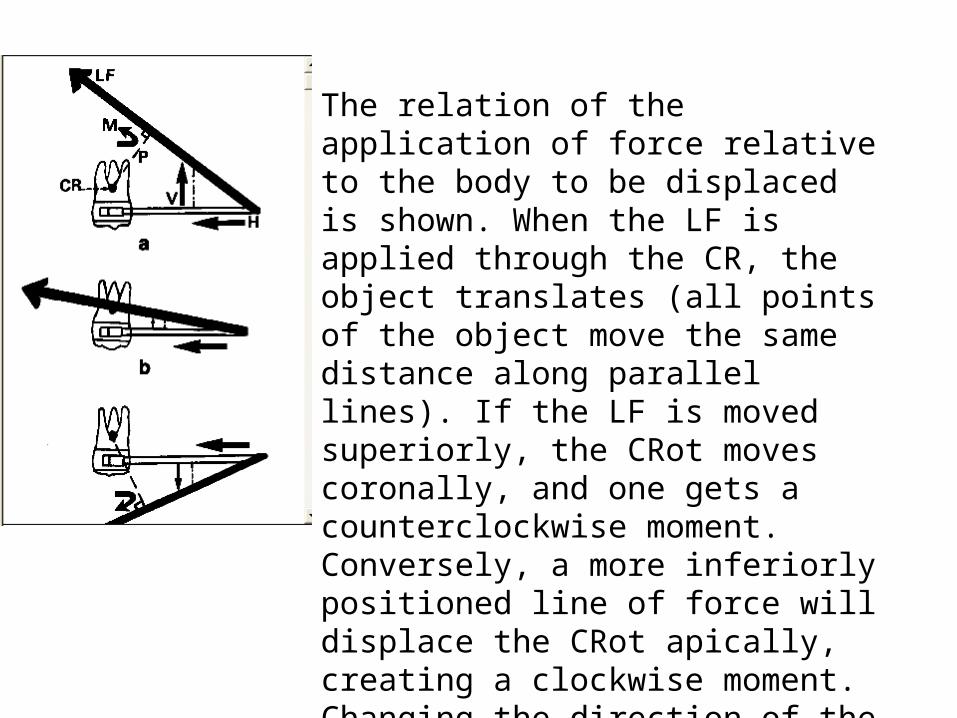
The relation of the application of force relative to the body to be displaced is shown. When the LF is applied through the CR, the object translates (all points of the object move the same distance along parallel lines). If the LF is moved superiorly, the CRot moves coronally, and one gets a counterclockwise moment. Conversely, a more inferiorly positioned line of force will displace the CRot apically, creating a clockwise moment. Changing the direction of the line of force also determines the vertical forces that are often overlooked, but so extremely important in orthodontic treatment.

The magnitude of the moment produced by the headgear is calculated by multiplying the perpendicular distance (P) from the LF to the CR by the magnitude of the force. Thus, for a given force, the greater the distance from the CR that the force is applied, the greater will be the moment. A comprehensive understanding of the potential, limitations, and undesirable side-effects can be gained by understanding the mechanical principles involved in its application. We can now apply our basic principles to assess force systems applied by various headgear designs.
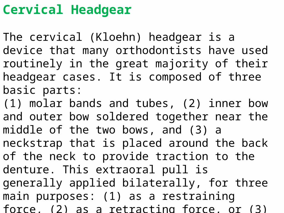
Cervical Headgear
The cervical (Kloehn) headgear is a device that many orthodontists have used routinely in the great majority of their headgear cases. It is composed of three basic parts: (1) molar bands and tubes, (2) inner bow and outer bow soldered together near the middle of the two bows, and (3) a neckstrap that is placed around the back of the neck to provide traction to the denture. This extraoral pull is generally applied bilaterally, for three main purposes: (1) as a restraining force, (2) as a retracting force, or (3) as a supplementary force.
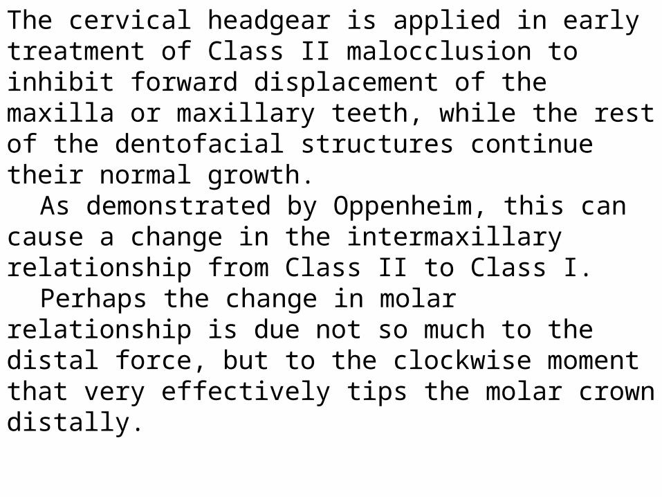
The cervical headgear is applied in early treatment of Class II malocclusion to inhibit forward displacement of the maxilla or maxillary teeth, while the rest of the dentofacial structures continue their normal growth.
As demonstrated by Oppenheim, this can cause a change in the intermaxillary relationship from Class II to Class I.
Perhaps the change in molar relationship is due not so much to the distal force, but to the clockwise moment that very effectively tips the molar crown distally.
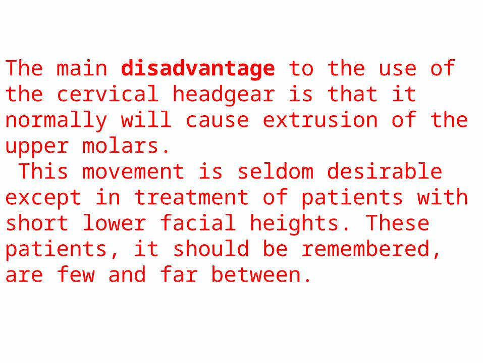
The main disadvantage to the use of the cervical headgear is that it normally will cause extrusion of the upper molars. This movement is seldom desirable except in treatment of patients with short lower facial heights. These patients, it should be remembered, are few and far between.
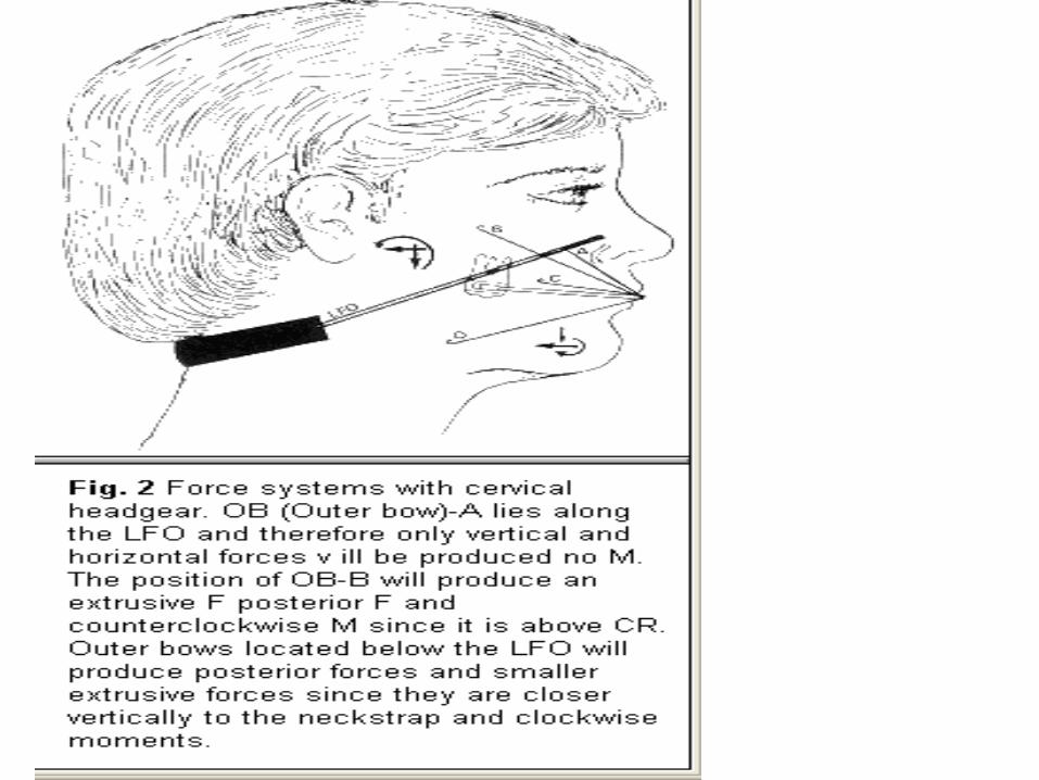

The different moments and forces produced by the cervical headgear depend on the situation of the outer bow in relation to the LFO. By definition, when the outer bow lies along the LFO, no moment occurs, and the force system will be reduced to a bodily movement in a posterior and extrusive direction. If the outer bow is placed above this line, the moment produced by the force will be in a counterclockwise direction. On the other hand, if the outer bow is adjusted below this line the moment created will be clockwise. However, the direction of the forces are the same - extrusive and posterior. It should be noted though that there is an exception to this rule. If the outer bow is located below the neckstrap, the resultant force will be a small intrusive one, instead of extrusive. Of course, a distal force and large clockwise moment will also be produced.

The direction of pull provided by the cervical headgear is especially advantageous in treating short-face Class II maxillary protrusive cases with low mandibular plane angles and deep bites, where it is desirable to extrude the upper posterior teeth. Also, the clockwise moment that is so readily produced with this headgear is very effective in helping conserve anchorage in extraction cases.

High-Pull Headgear
The high-pull headgear, like the cervical-pull, is analyzed using the same principles of force and moment production described before. This style headgear always produces an intrusive and posterior direction of pull, due to the position of the headcap.The direction of the moment that is produced is dependent on the position of the outer bow.

• If the outer bow is placed anterior to the LFO, either above or below the occlusal plane level, the moment produced will be counterclockwise. On the other hand, if the outer bow is placed posterior to this line, the moment produced will be in a clockwise direction. The magnitude of this moment will be proportional to the distance of the outer bow to the CR. If a distal and intrusive movement with no moment is desired, the outer bow must be placed somewhere along the LFO. This force system would be beneficial in a long-face Class II patient with a high mandibular plane angle, where intrusion of maxillary molars would decrease facial height and improve the facial profile.
Straight-Pull Headgear
This style headgear is a combination of the high-pull and cervical headgear, with the advantage of increased versatility. Depending on the force system desired, the orthodontist has the opportunity to change the location of the LFO.The prime advantage of this headgear is its ability to produce an essentially pure posterior translatory force. This is accomplished by placing the LFO through the center of resistance, parallel to the occlusal plane. Clinically, this means bending the outer bow to the same level as CR, and hooking the elastic to a notch at the same vertical level.
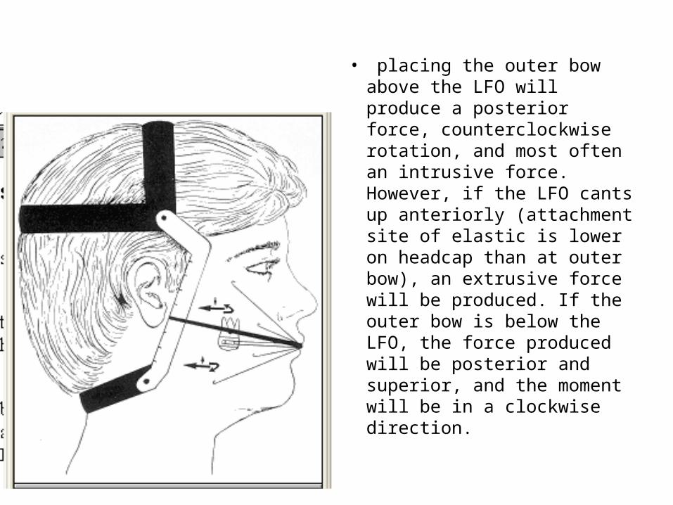
• placing the outer bow above the LFO will produce a posterior force, counterclockwise rotation, and most often an intrusive force. However, if the LFO cants up anteriorly (attachment site of elastic is lower on headcap than at outer bow), an extrusive force will be produced. If the outer bow is below the LFO, the force produced will be posterior and superior, and the moment will be in a clockwise direction.
The straight-pull is the headgear of choice in a Class II malocclusion with no vertical problems. It is also the headgear of preference when the main thrust of headgear wear is to prevent anterior migration of maxillary teeth, or possibly even translate them posteriorly.

Vertical-Pull Headgear
The main purpose of this headgear is to produce an intrusive direction of force to maxillary teeth, with posteriorly directed forces. If the outer bow is hooked to the headcap so that the line of force is perpendicular to the occlusal plane and through the CR, pure intrusion may take place.
Due to the multiple notches in the headcap, this headgear is also very versatile, as the LFO orientation may be changed. However, upon establishing the LFO, our principles of determining force systems produced remains unchanged.

• The head is divided into two components: the anterior component from the LFO forward and the posterior component located behind the LFO. If the outer bow is placed anywhere in the anterior compartment, the moment created will be counterclockwise, and the forces produced will be intrusive and posterior. If the outer bow is placed anywhere in the posterior section, the moment will be clockwise and the vertical force will be intrusive, but the horizontal force will be forward. If this latter force system is desired, it will require inserting the inner bow into the buccal headgear tube from the distal.
•The vertical-pull headgear is not as commonly used as are the others. However, it is very useful when pure intrusion of buccal segments is required, as in the Class I open-bite patient.
Conclusion
The main steps in designing a headgear to deliver the desired force system are as follows:1. Locate the center of resistance of the object (i.e., entire maxillary arch, first molar only, etc.) to which the force is to be applied.2. Construct the "O moment line of force" (LFO) based on force direction requirements. The choice of headcap or neckstrap is therebydetermined.3. Based on the desired direction and magnitude of the moment, position the outer bow relative to the LFO.


