Dynamic Modeling of a Batch Dynamic Modeling of a Batch Bioreactor for Trans- Bioreactor for Trans- esterification of Waste esterification of Waste Vegetable Oil Vegetable Oil Progress Report Presentation Progress Report Presentation Nabeel A. Adeyemi Nabeel A. Adeyemi Ph D Ph D (Engineering) (Engineering) G0828727 G0828727 Supervisors: Prof AKM Mohiuddin Supervisors: Prof AKM Mohiuddin 1 st April 2010
Transcript
Dynamic Modeling of a Batch Dynamic Modeling of a Batch Bioreactor for Trans-Bioreactor for Trans-esterification of Waste esterification of Waste
Nabeel A. AdeyemiNabeel A. Adeyemi Ph DPh D (Engineering) (Engineering)
G0828727G0828727
Supervisors: Prof AKM MohiuddinSupervisors: Prof AKM MohiuddinAssoc Prof Dr Tariq JameelAssoc Prof Dr Tariq Jameel
1st April 2010
• Research Overview– Introduction– Problem statement– Significance– Research Philosophy/ Hypothesis– Objective
• Progress Report November 2009-April 2010– Methodology– Results
• Discussion/ Challenges• On-going experiment • Outstanding work• Modified Work Plan /Reviewed Gantt Chart/
Milestone• Publication
Research Overview
4
Introduction
• Renewable/alternative energy sourcesRenewable/alternative energy sources– Biodiesel Biodiesel an alternative energy sourcean alternative energy source
• Similar physical & chemical properties to fuel used in Similar physical & chemical properties to fuel used in Internal Combustion enginesInternal Combustion engines
• Driving forceDriving force– Socio-politics of petro-diesel (price, Socio-politics of petro-diesel (price,
availability) availability) – Environmental effect of petro-dieselEnvironmental effect of petro-diesel
WVO– Degraded culinary property– Tri, Di- and Mono-glyceride
• High Free fatty acid (FFA) >3%• High water content
Soap Formation
Introduction (Cont’d)(Cont’d)
Introduction (Cont’d)(Cont’d)
Biodiesel Generation (Reversible reaction)
TG + Alcohol DG + Fatty Acid Methyl Ester
DG + Alcohol MG + Fatty Acid Methyl Ester
MG + Alcohol G + Fatty Acid Methyl Ester
Acid / Alkali Catalyst
Alcohol
(Straight Chain)
Transesterification
Reaction stops abruptly after first few minutes and reverses, limiting conversion of TG,DG,MG to Biodiesel
Problem Statement Present Biodiesel yield from neat vegetable oil is
80-85%. It will be lower with WVO with the normal transesterification route due to FFA and moisturemass transfer and kinetics limited.
Variables investigated affecting reaction kinetics in batch reactors have been limited to temperature, catalyst ratio, alcohol type, water content and FFA. factors such as hydrodynamic effects are not considered
Laboratory kinetics data acquired from reactors cannot to translated for industrial production with reaction kinetics model alone.
Significance
Since the transesterification involves mixing, consideration of reactor hydrodynamics due to non-kinetics variables (impeller position, size, baffles etc) in relationship to the reactor, along with reaction kinetics would provide greater insight and enable exploration of the transesterification process beyond the use traditional kinetics variable.
Research Philosophy/Hypothesis
If Dynamic Modeling, which has not been extended to transesterification, is applied to waste vegetable oil transesterification, biodiesel yield can be predicted and improved.
ease the exploration of the use of non food oils for biodiesel production and establish the limitation of this approach.
With significant hydrodynamics detail and lesser experimental data, Dynamic Models can successfully determine the number of independent reactions and the corresponding stoichiometries that can show higher yields compared to purely data-driven experimental models.
Also, emphasis on analytical rather than experimental optimzation can be used successfully without extensive reaction kinetics.
ObjectiveThe broad objective is to model the transesterification
of waste vegetable oil in a batch reactor using dynamic modeling approach
Specifically to;– explore the effect due to impeller and baffle on
biodiesel yield and reaction kinetics in a 2 litre batch reactor during trans-esterification of WVO
– develop a dynamic model taking into account effect of due hydrodynamics during trans-esterification in a batch reactor
– evaluate and validate the performance of the model process with a view to optimize the process.
Progress Report
November 2009-April 2010
Methodology 1. Literature review (Jan 2009-till date)2. Characterization - WVO and
transesterification parameter.A.Collection of WVO/ FFA analysis/ Fatty Acid
profilea) titrimetric method for FFA content. The analysis was
replicated twice for three different samples of WVO. (AOCS Official Method Ca 5a-40:1)
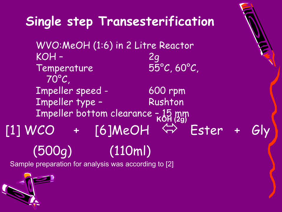
B. Transesterification of WVO at varying impeller/baffle position• WVO:MeOH (1:6) in 2 Litre Reactor (KOH as catalyst) at
55°C, 60°C, 70°C, 600 rpm• GC-MS Analysis of transesterified WVO for TG, DG,
MG, Glyerol content
1) Develop transport and kinetics model for simulation in CFD
• Reaction transport coupling • Comparison of (3) with
transesterification process data• Evaluation/ Validation Dynamic
Model
Methodology (Cont’d)
GC-MS Configuration• The analysis was
performed on an Agilent 6890/ 5973 GC/MSD system. Automated split injection was performed using an Agilent 7683 automatic sampler.
2 minsolvent delay
250°CMS source
150°CMS quad
(40-500amu), threshold 100
MSD parameter Scan
50°C, 1 minDetector temperature AUX 2
1 minoven temperature
heliumcarrier gas
1/50split ratio
1µminjection volume
250°Cinlet temperature
Table 1. GC-MS configuration
Methodology (Cont’d)
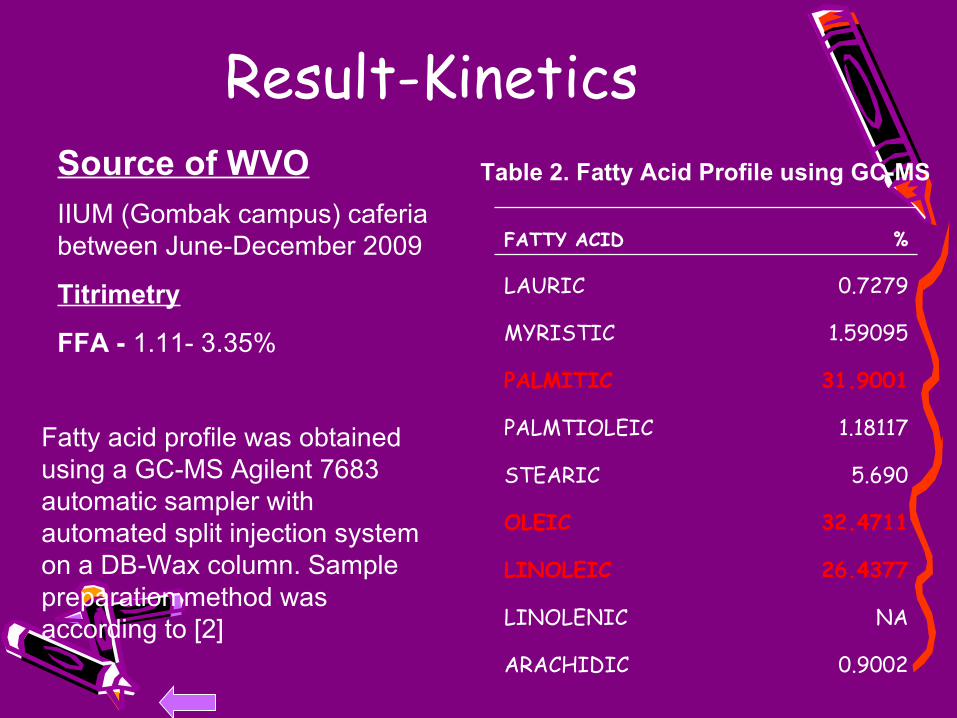
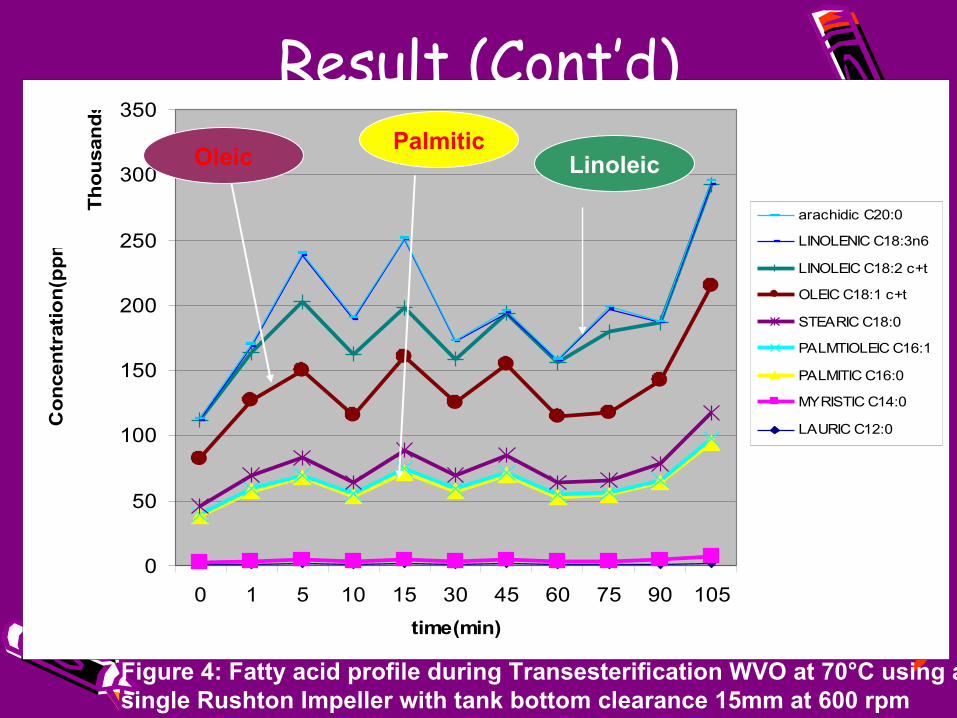
Result-Kinetics
0.9002ARACHIDIC
NALINOLENIC
26.4377LINOLEIC
32.4711OLEIC
5.690STEARIC
1.18117PALMTIOLEIC
31.9001PALMITIC
1.59095MYRISTIC
0.7279LAURIC
%FATTY ACID
Table 2. Fatty Acid Profile using GC-MS
Fatty acid profile was obtained using a GC-MS Agilent 7683 automatic sampler with automated split injection system on a DB-Wax column. Sample preparation method was according to [2]
Source of WVOIIUM (Gombak campus) caferia between June-December 2009
Titrimetry
FFA - 1.11- 3.35%
Single step Transesterification
[1] WCO + [6]MeOH Ester + Gly (500g) (110ml)
KOH (2g)
Sample preparation for analysis was according to [2]
the reactor-fluid was modeled as a 2D axisymmetrical body and COMSOL Multiphysics 3.5a was used to obtain the velocity profile and hydrodynamic component of the Navier Stokes’ equation. (Fig 5-8)
Boundary conditions for the tank wall, liquid surface, impeller walls were selected as in [3]
Figure 5a: axial
velocity profile present work
Figure 5b: axial velocity profile of experimentally validated model Ochieng et al, 2008 [4]
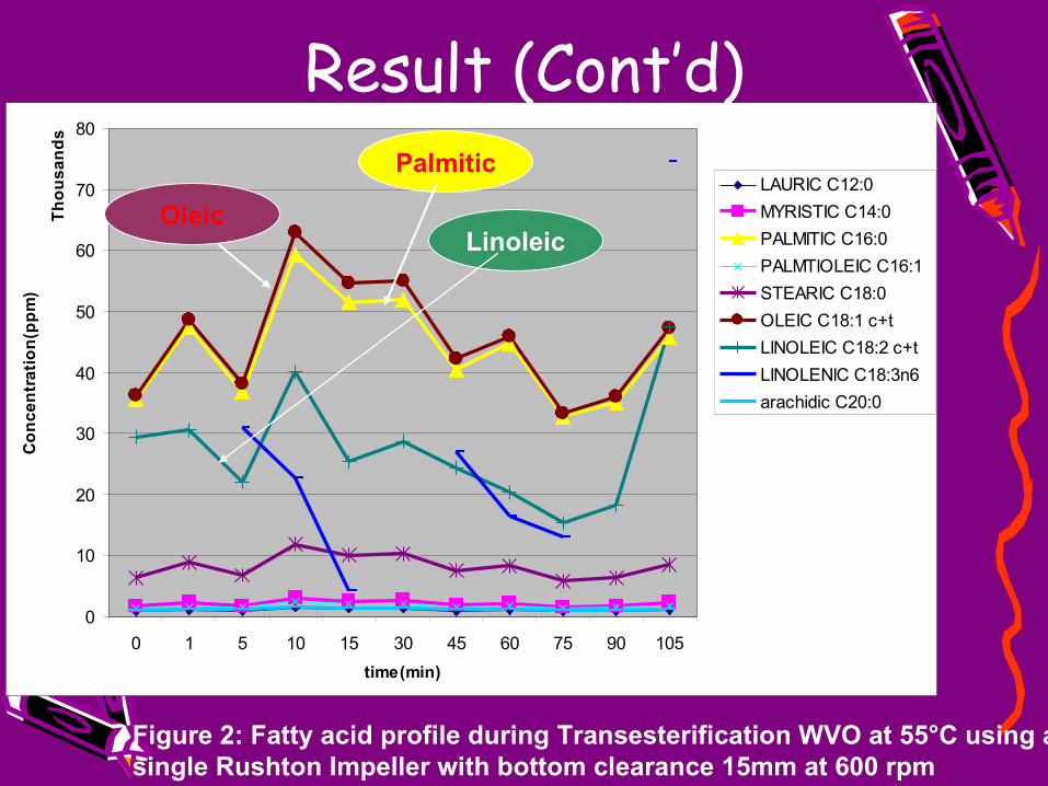
Result (Cont’d)
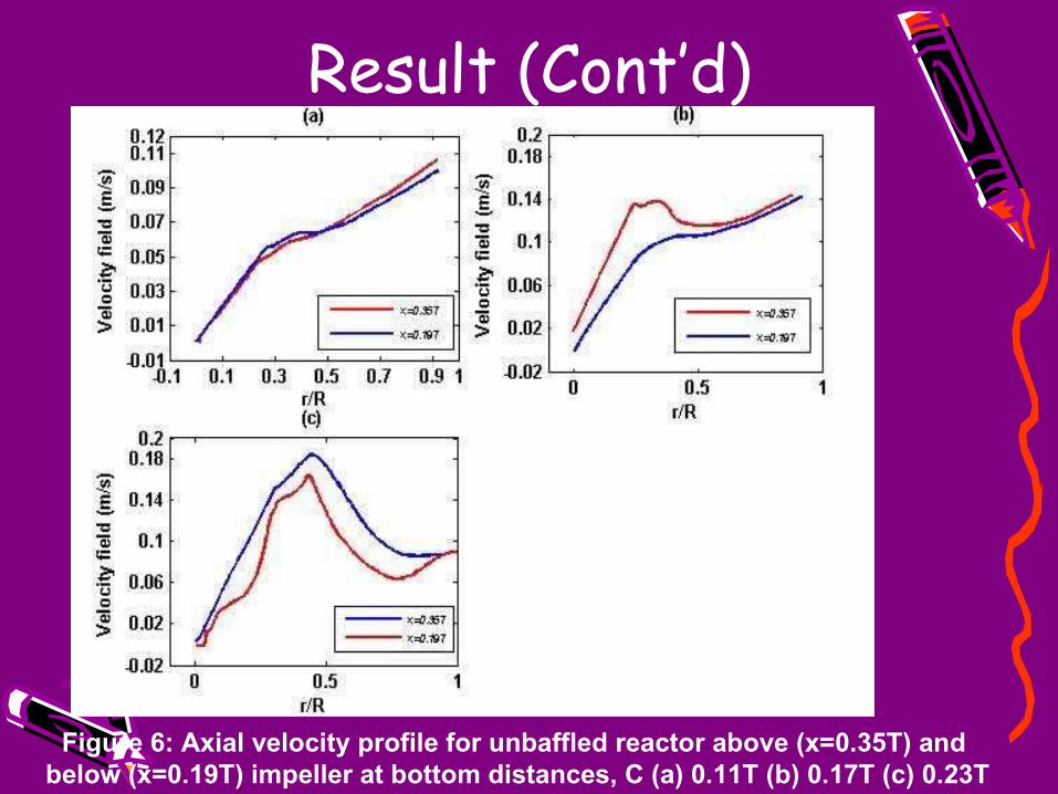
Figure 6: Axial velocity profile for unbaffled reactor above (x=0.35T) and below (x=0.19T) impeller at bottom distances, C (a) 0.11T (b) 0.17T (c) 0.23T
Result (Cont’d)
Figure 7: Simulated mean tangential, radial and axial velocity at impeller bottom Clearance, C= 0.11T, 0.15T, 0.19T, 0.23T and 0.27T for unbaffled
Result (Cont’d)
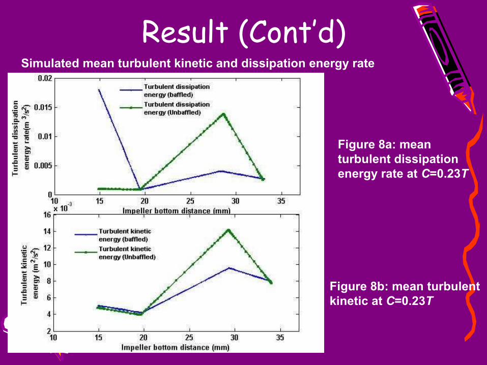
Simulated mean turbulent kinetic and dissipation energy rate
Figure 8b: mean turbulent kinetic at C=0.23T
Figure 8a: mean turbulent dissipation energy rate at C=0.23T
Result (Cont’d)
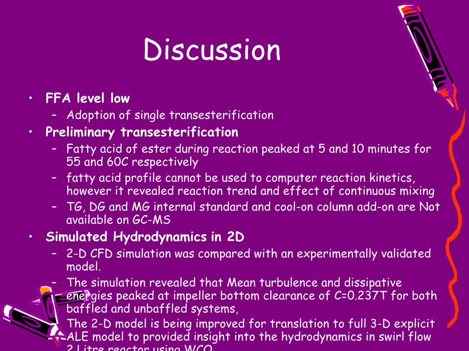
Discussion• FFA level low
– Adoption of single transesterification• Preliminary transesterification
– Fatty acid of ester during reaction peaked at 5 and 10 minutes for 55 and 60C respectively
– fatty acid profile cannot be used to computer reaction kinetics, however it revealed reaction trend and effect of continuous mixing
– TG, DG and MG internal standard and cool-on column add-on are Not available on GC-MS
• Simulated Hydrodynamics in 2D– 2-D CFD simulation was compared with an experimentally validated
model.– The simulation revealed that Mean turbulence and dissipative
energies peaked at impeller bottom clearance of C=0.237T for both baffled and unbaffled systems,
– The 2-D model is being improved for translation to full 3-D explicit ALE model to provided insight into the hydrodynamics in swirl flow 2 Litre reactor using WCO..
On-going experiment• Transesterification of WVO at
Outstanding work• Transesterification at three temperature
and three reactor bottom distance • Obtain conversion of TG, DG and MG in
GC-MS (Cool-on column)• Reactive Mixing simulation• Evaluation/ validation of Dynamic Model
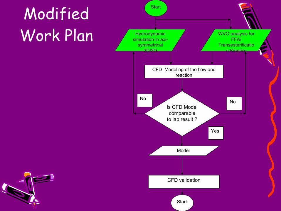
Modified Work Plan
CFD Modeling of the flow and reaction
WVO analysis for FFA/
Transesterification Kinetics
Hydrodynamic simulation in axi-
symmetrical 2D/3D
Start
Model
Is CFD Model comparable
to lab result ?
NoNo
Yes
Start
CFD validation
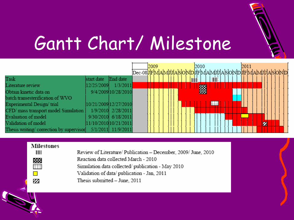
Gantt Chart/ Milestone
Publications• Investigating Hydrodynamic Effects During Mixing in a 2 L
Reactor Using CFD for Waste Cooking Oil Transesterification accepted for presentation at the Asia Modelling Symposium 2010 Kota Kinabalu, Malaysia May 26, 2010 - May 28,
• Biodiesel production: A Comparative Review submitted to the International Energy Journal
References• 1. Dias, J., M. Alvim-Ferraz, and M. Almeida, Comparison of the
performance of different homogeneous alkali catalysts during transesterification of waste and virgin oils and evaluation of biodiesel quality. Fuel, 2008.
• 2. David, F., P. Sandra, and P. Wylie, Improving the analysis of fatty acid methyl esters using retention time locked methods and retention time databases. Agilent Technologies Application Note, 2002.
• 3. Chemical Engineering Module User’s Guide Version 3.5a• 4. Ochieng, A., et al., Mixing in a tank stirred by a Rushton turbine at a low
clearance. Chemical Engineering and Processing: Process Intensification, 2008. 47(5): p. 842-851