24
BioTector Compressor USER MANUAL October 2017, Edition 2.01a Original Instructions © Copyright BioTector 2017. All rights reserved. Printed by BioTector in the Republic of Ireland.
BioTector Compressor
USER MANUAL
October 2017, Edition 2.01a
Original Instructions
© Copyright BioTector 2017. All rights reserved. Printed by BioTector in the Republic of Ireland.
Page 2 of 24
Table of Contents
1. SAFETY PRECAUTIONS ............................................................................................................................ 3
1.1 GENERAL SAFETY PRECAUTIONS .............................................................................................................. 3 1.2 PRECAUTIONARY LABELS ATTACHED TO THE INSTRUMENT ..................................................................... 4 1.3 POTENTIAL SYSTEM SAFETY HAZARDS ..................................................................................................... 5 1.4 ELECTRICAL AND BURN PRECAUTIONS ..................................................................................................... 6
2. SPECIFICATIONS AND OPERATING CONDITIONS. ............................................................................. 7
3. MAINS CONNECTION TO THE BIOTECTOR COMPRESSOR .............................................................. 8
4. POSITION OF COMPRESSED AIR OUTLET ON COMPRESSOR ........................................................ 9
4.1 LEFT SIDE AIR OUTLET (DEFAULT) ........................................................................................................... 9 4.2 RIGHT SIDE AIR OUTLET .......................................................................................................................... 10
5. COMMISSIONING AND STARTUP .......................................................................................................... 11
6. OPERATION ............................................................................................................................................... 13
6.1 ACTIVATE THE BIOTECTOR COMPRESSOR .............................................................................................. 13 6.2 DEACTIVATE AND ISOLATE THE BIOTECTOR COMPRESSOR ................................................................... 13
7. DRAWINGS................................................................................................................................................. 14
7.1 81101005 – B7000I & B3500 COMPRESSOR TO BIOTECTOR ELECTRICAL WIRING ........................... 14 7.2 81105041 – B3500 COMPRESSOR TO BIOTECTOR ELECTRICAL WIRING ............................................ 15 7.3 81104059 (SUBSET) – COMPRESSOR PNEUMATIC LAYOUT .................................................................. 16 7.4 81101004 – COMPRESSOR PNEUMATIC LAYOUT .................................................................................. 17 7.5 81805022 – B3500 PNEUMATIC CONNECTION ...................................................................................... 18 7.6 81804091 (SUBSET) - B7000I PNEUMATIC CONNECTION ..................................................................... 19
8. SERVICE & MAINTENANCE .................................................................................................................... 19
9. TROUBLESHOOTING ............................................................................................................................... 21
10. BIOTECTOR COMPRESSOR SYSTEM REPLACEMENT AND SPARE PARTS LIST ............... 22
Page 3 of 24
1. Safety Precautions Please read this manual before unpacking, setting up, or operating the BioTector Compressor. The BioTector Compressor should only be used by qualified trained staff and only for the purpose it is intended for. Do not use or install this equipment in any way other than the methods specified in this manual. The procedures and methods described in this manual are based on assuming the user has a basic, fundamental background in electrical equipment installation and wiring.
1.1 General Safety Precautions Please pay attention to all caution, warning and danger statements at all times. Non-observance of the safety instructions can result in serious personal injury, death or damage to the equipment. Therefore observe the following:
▪ Only engineers trained by the manufacturer should carry out maintenance on the compressor. ▪ The power supplies contain capacitors that are charged to hazardous voltages. After
disconnecting the main power, allow at least one minute for discharge before opening the control section.
▪ Never wash or spray the system with water. Do not allow water to enter the BioTector Compressor enclosure.
▪ Protect the system from one-sided heat radiation, direct sunlight and vibration. System must be installed in a dry, dust-free room. Special precautions are required in environments with corrosive gases, vapors or explosion risk.
▪ Please do not place anything on top of the BioTector Compressor enclosure. ▪ All connections and hoses should be kept clean and free of grease, oil and other combustible
materials. ▪ Gasses under pressure may be present within the system. Valves should be opened and closed
slowly, and safety glasses and proper safety gears should be worn at all times while gasses are being vented.
▪ Ensure that the compressor is installed in a well-ventilated area. If the location is occupied, then sufficient ventilation must be provided in the location. At least 6 air changes per hour are necessary.
▪ The installation must comply with local regulations for the installation of electrical devices, and for the installation of compressed air systems.
▪ The compressor should only be used by qualified staff and for the purpose it is intended for. Do not attempt to modify or enhance the performance of a compressor in any way. Pay attention to the safety warnings at all times.
Please note if the instructions in this manual are not followed, the operation and protection provided by the equipment may be impaired.
Page 4 of 24
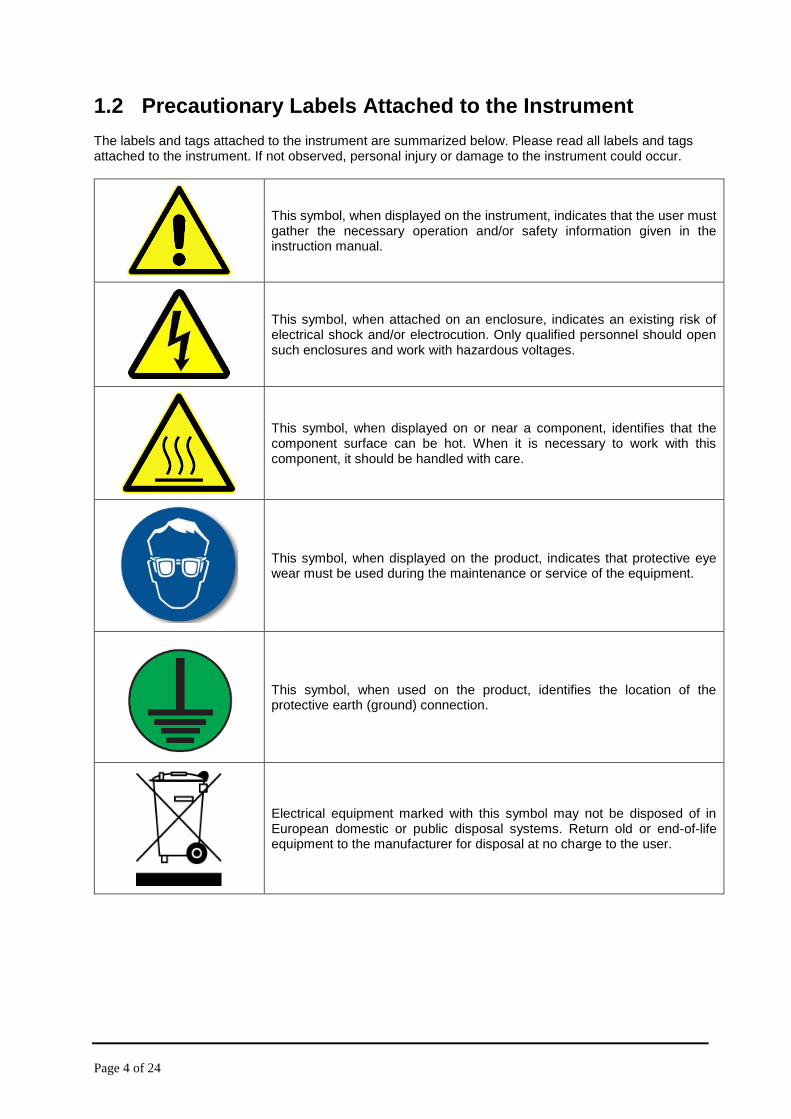
1.2 Precautionary Labels Attached to the Instrument The labels and tags attached to the instrument are summarized below. Please read all labels and tags attached to the instrument. If not observed, personal injury or damage to the instrument could occur.
This symbol, when displayed on the instrument, indicates that the user must gather the necessary operation and/or safety information given in the instruction manual.
This symbol, when attached on an enclosure, indicates an existing risk of electrical shock and/or electrocution. Only qualified personnel should open such enclosures and work with hazardous voltages.
This symbol, when displayed on or near a component, identifies that the component surface can be hot. When it is necessary to work with this component, it should be handled with care.
This symbol, when displayed on the product, indicates that protective eye wear must be used during the maintenance or service of the equipment.
This symbol, when used on the product, identifies the location of the protective earth (ground) connection.
Electrical equipment marked with this symbol may not be disposed of in European domestic or public disposal systems. Return old or end-of-life equipment to the manufacturer for disposal at no charge to the user.

Page 5 of 24
1.3 Potential System Safety Hazards The two main potential safety hazards associated with running the BioTector Compressor are:
1. Electrical hazards. 2. Pressurized air hazards.
Please read the instructions in this manual carefully before installing or starting the compressor. The manufacturer cannot accept liability for damages due to non-observance of this manual. Use of spare parts not supplied by the manufacturer will invalidate the warranty. The manufacturer shall not be liable for omissions or errors contained herein or for incidental or consequential damages in connection with the furnishing, performance, or use of this material. The information contained in this manual is subject to change without notice. The information contained herein is protected by copyright. Reproduction, adaptation, or translation of any part of this manual without prior written permission is prohibited, except as allowed under the copyright laws. Product names mentioned herein are for identification purposes only and may be trademarks or registered trademarks of their respective companies. Where manuals are translated into several languages, the source language text is considered as the original.
Maintenance and operation should not be carried out unless personnel have been fully trained in the operation of the compressor.
Caution

Page 6 of 24
1.4 Electrical and Burn Precautions
During system installation, maintenance or servicing:
• Isolate the system power lines before starting any work in the electrical/electronic compartment inside the BioTector Compressor enclosure.
• All electrical work should be carried out by qualified electrical personnel only.
• Comply with all local and national regulations when working with electrical connections.
• Make sure the system is properly earthed (grounded) before switching on.
• It is required to connect the mains through an external isolator (2-pole disconnection switch), and connect the mains through an earth leakage circuit breaker.
• When working with hot surfaces, use protective gloves and handle the components with care.
The BioTector Compressor contains electrical components operating under high voltages. Contact may result in electric shock and severe or fatal injury.
DANGER
Page 7 of 24
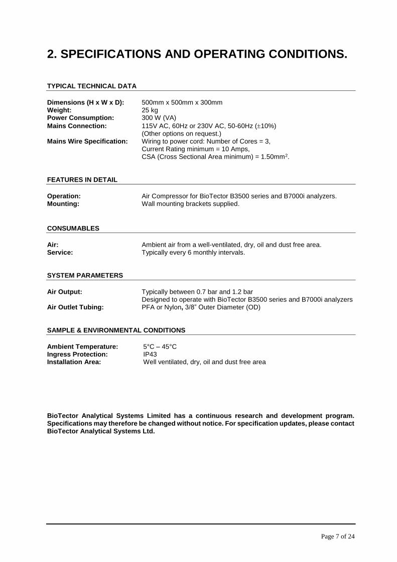
2. SPECIFICATIONS AND OPERATING CONDITIONS. TYPICAL TECHNICAL DATA
Dimensions (H x W x D): 500mm x 500mm x 300mm Weight: 25 kg Power Consumption: 300 W (VA)
Mains Connection: 115V AC, 60Hz or 230V AC, 50-60Hz (10%) (Other options on request.) Mains Wire Specification: Wiring to power cord: Number of Cores = 3, Current Rating minimum = 10 Amps, CSA (Cross Sectional Area minimum) = 1.50mm2. FEATURES IN DETAIL
Operation: Air Compressor for BioTector B3500 series and B7000i analyzers. Mounting: Wall mounting brackets supplied.
CONSUMABLES
Air: Ambient air from a well-ventilated, dry, oil and dust free area. Service: Typically every 6 monthly intervals. SYSTEM PARAMETERS
Air Output: Typically between 0.7 bar and 1.2 bar Designed to operate with BioTector B3500 series and B7000i analyzers Air Outlet Tubing: PFA or Nylon, 3/8” Outer Diameter (OD) SAMPLE & ENVIRONMENTAL CONDITIONS
Ambient Temperature: 5°C – 45°C Ingress Protection: IP43 Installation Area: Well ventilated, dry, oil and dust free area BioTector Analytical Systems Limited has a continuous research and development program. Specifications may therefore be changed without notice. For specification updates, please contact BioTector Analytical Systems Ltd.
Page 8 of 24
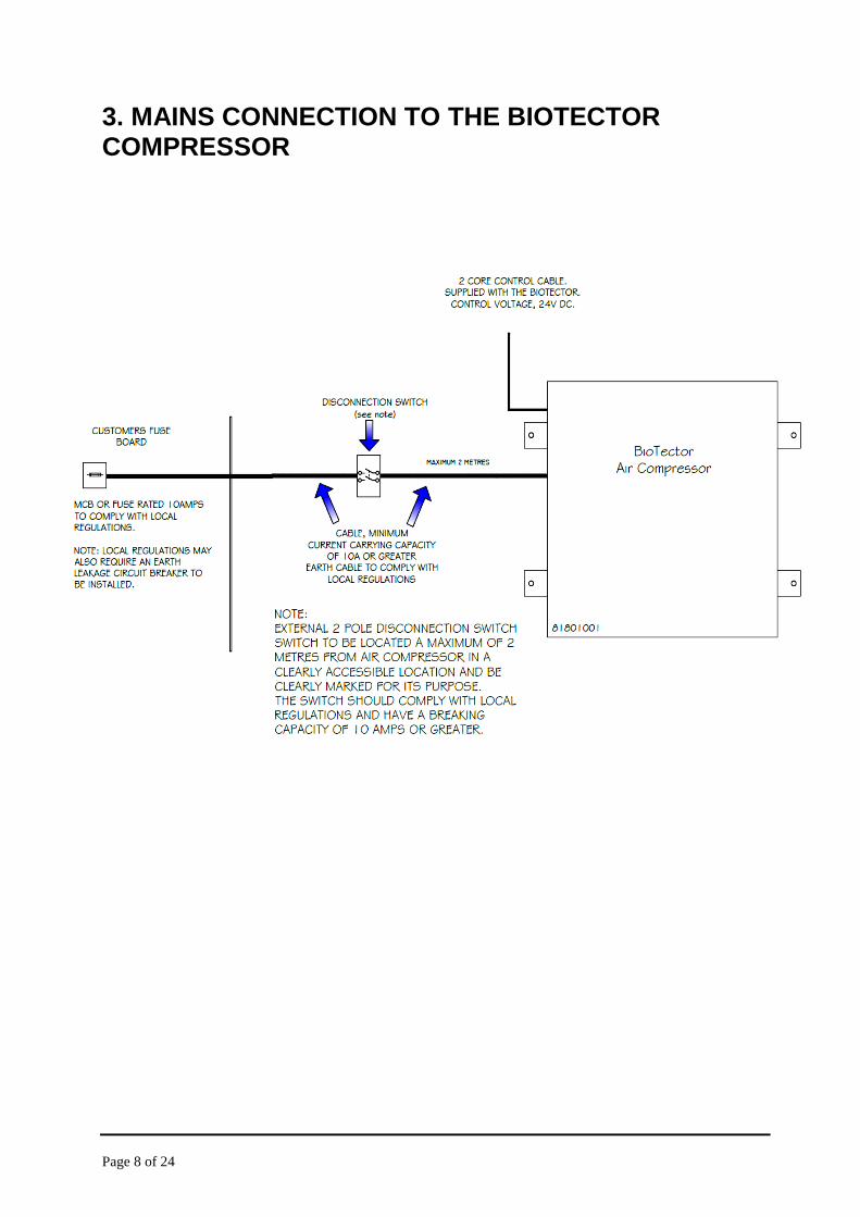
3. MAINS CONNECTION TO THE BIOTECTOR COMPRESSOR
Page 9 of 24
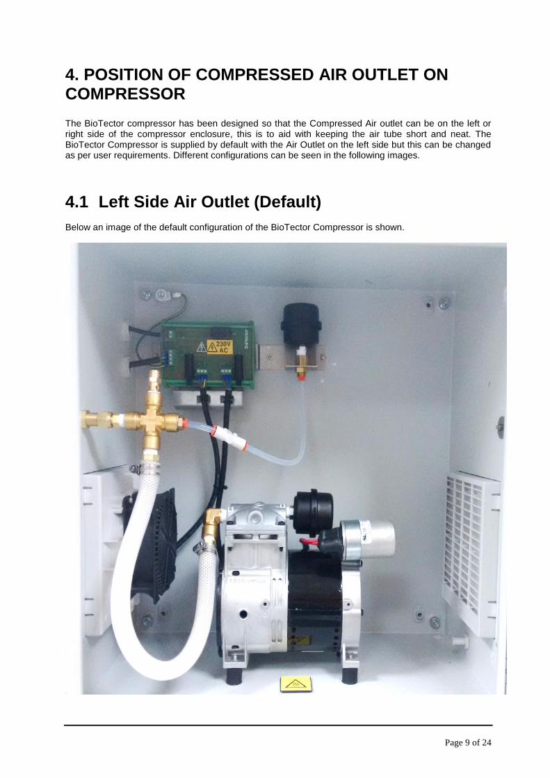
4. POSITION OF COMPRESSED AIR OUTLET ON COMPRESSOR The BioTector compressor has been designed so that the Compressed Air outlet can be on the left or right side of the compressor enclosure, this is to aid with keeping the air tube short and neat. The BioTector Compressor is supplied by default with the Air Outlet on the left side but this can be changed as per user requirements. Different configurations can be seen in the following images.
4.1 Left Side Air Outlet (Default) Below an image of the default configuration of the BioTector Compressor is shown.
Page 10 of 24
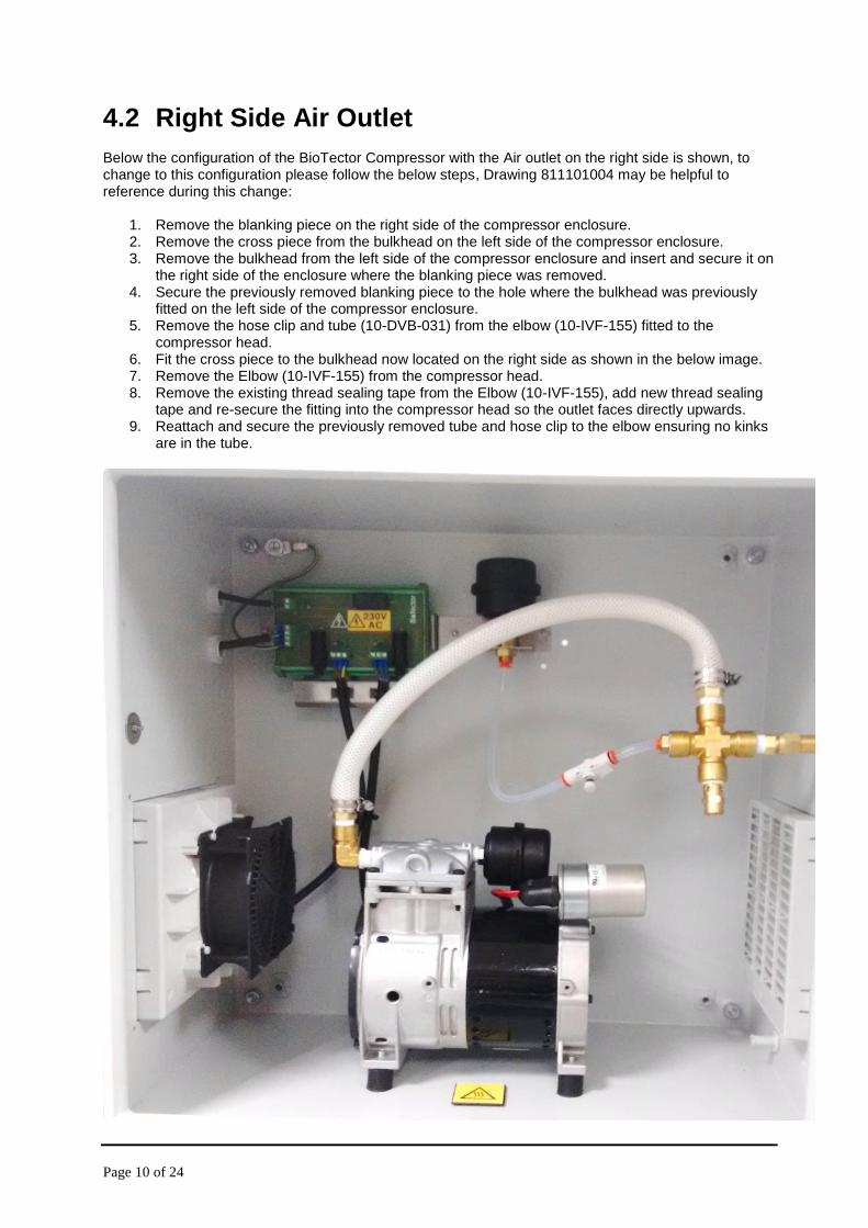
4.2 Right Side Air Outlet Below the configuration of the BioTector Compressor with the Air outlet on the right side is shown, to change to this configuration please follow the below steps, Drawing 811101004 may be helpful to reference during this change:
1. Remove the blanking piece on the right side of the compressor enclosure. 2. Remove the cross piece from the bulkhead on the left side of the compressor enclosure. 3. Remove the bulkhead from the left side of the compressor enclosure and insert and secure it on
the right side of the enclosure where the blanking piece was removed. 4. Secure the previously removed blanking piece to the hole where the bulkhead was previously
fitted on the left side of the compressor enclosure. 5. Remove the hose clip and tube (10-DVB-031) from the elbow (10-IVF-155) fitted to the
compressor head. 6. Fit the cross piece to the bulkhead now located on the right side as shown in the below image. 7. Remove the Elbow (10-IVF-155) from the compressor head. 8. Remove the existing thread sealing tape from the Elbow (10-IVF-155), add new thread sealing
tape and re-secure the fitting into the compressor head so the outlet faces directly upwards. 9. Reattach and secure the previously removed tube and hose clip to the elbow ensuring no kinks
are in the tube.
Page 11 of 24
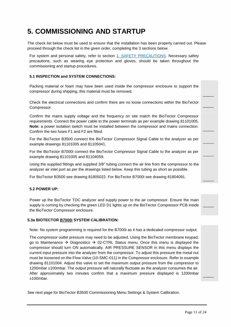
5. COMMISSIONING AND STARTUP
The check list below must be used to ensure that the installation has been properly carried out. Please
proceed through the check list in the given order, completing the 3 sections below.
For system and personal safety, refer to section 1. SAFETY PRECAUTIONS. Necessary safety
precautions, such as wearing eye protection and gloves, should be taken throughout the
commissioning and startup procedures.
5.1 INSPECTION and SYSTEM CONNECTIONS:
Packing material or foam may have been used inside the compressor enclosure to support the
compressor during shipping, this material must be removed.
Check the electrical connections and confirm there are no loose connections within the BioTector
Compressor.
_____
_____
Confirm the mains supply voltage and the frequency on site match the BioTector Compressor
requirements. Connect the power cable to the power terminals as per example drawing 81101005,
Note: a power isolation switch must be installed between the compressor and mains connection.
Confirm the two fuses F1 and F2 are fitted.
_____
For the BioTector B3500 connect the BioTector Compressor Signal Cable to the analyzer as per
example drawings 81101005 and 81105041. _____
For the BioTector B7000i connect the BioTector Compressor Signal Cable to the analyzer as per
example drawing 81101005 and 81104059. _____
Using the supplied fittings and supplied 3/8” tubing connect the air line from the compressor to the
analyzer air inlet port as per the drawings listed below. Keep this tubing as short as possible.
For BioTector B3500 see drawing 81805022. For BioTector B7000i see drawing 81804091.
_____
5.2 POWER UP:
Power up the BioTector TOC analyzer and supply power to the air compressor. Ensure the main
supply is coming by checking the green LED D1 lights up on the BioTector Compressor PCB inside
the BioTector Compressor enclosure.
_____
5.3a BIOTECTOR B7000i SYSTEM CALIBRATION:
Note: No system programming is required for the B7000i as it has a dedicated compressor output.
The compressor outlet pressure may need to be adjusted. Using the BioTector membrane keypad,
go to Maintenance Diagnostics 02-CTRL Status menu. Once this menu is displayed the
compressor should turn ON automatically. AIR PRESSURE SENSOR in this menu displays the
current input pressure into the analyzer from the compressor. To adjust this pressure the metal nut
must be loosened on the Flow Valve (10-SMC-011) in the Compressor enclosure. Refer to example
drawing 81101004. Adjust this valve to set the maximum output pressure from the compressor to
1200mbar ±100mbar. The output pressure will naturally fluctuate as the analyzer consumes the air.
After approximately two minutes confirm that a maximum pressure displayed is 1200mbar
±100mbar.
_____
See next page for BioTector B3500 Commissioning Menu Settings & System Calibration.
Page 12 of 24
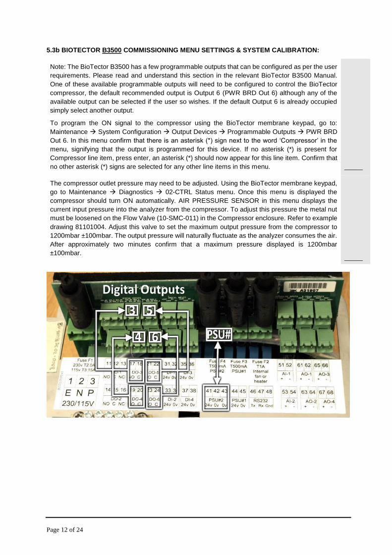
5.3b BIOTECTOR B3500 COMMISSIONING MENU SETTINGS & SYSTEM CALIBRATION:
Note: The BioTector B3500 has a few programmable outputs that can be configured as per the user
requirements. Please read and understand this section in the relevant BioTector B3500 Manual.
One of these available programmable outputs will need to be configured to control the BioTector
compressor, the default recommended output is Output 6 (PWR BRD Out 6) although any of the
available output can be selected if the user so wishes. If the default Output 6 is already occupied
simply select another output.
To program the ON signal to the compressor using the BioTector membrane keypad, go to:
Maintenance System Configuration Output Devices Programmable Outputs PWR BRD
Out 6. In this menu confirm that there is an asterisk (*) sign next to the word ‘Compressor’ in the
menu, signifying that the output is programmed for this device. If no asterisk (*) is present for
Compressor line item, press enter, an asterisk (*) should now appear for this line item. Confirm that
no other asterisk (*) signs are selected for any other line items in this menu.
_____
The compressor outlet pressure may need to be adjusted. Using the BioTector membrane keypad,
go to Maintenance Diagnostics 02-CTRL Status menu. Once this menu is displayed the
compressor should turn ON automatically. AIR PRESSURE SENSOR in this menu displays the
current input pressure into the analyzer from the compressor. To adjust this pressure the metal nut
must be loosened on the Flow Valve (10-SMC-011) in the Compressor enclosure. Refer to example
drawing 81101004. Adjust this valve to set the maximum output pressure from the compressor to
1200mbar ±100mbar. The output pressure will naturally fluctuate as the analyzer consumes the air.
After approximately two minutes confirm that a maximum pressure displayed is 1200mbar
±100mbar.
_____

Page 13 of 24
6. OPERATION The BioTector Compressor is controlled by the BioTector TOC Analyzer, the compressor is activated anytime pressurized air is required for the TOC Analyzer system operation.
6.1 Activate the BioTector Compressor Note: The Commissioning and Startup procedures are required to be complete prior to carrying out the below steps: To switch the compressor on:
1. Confirm that power is supplied to the BioTector Compressor. Confirm that the green LED D1 lights up on the BioTector Compressor PCB inside the BioTector Compressor enclosure.
2. When the commissioning and startup procedures are completed (see section 5. COMMISSIONING AND STARTUP for details) and the BioTector analyzer is started, the compressor will start operating automatically.
3. To manually activate the compressor the compressor operation, go to Maintenance Diagnostics O2-CTRL Status menu. The BioTector compressor will start operating once the user enters this menu. This menu also shows diagnostics of the Air and O2 parameters. The Compressor will de-activate approximately 10 seconds after the user exiting this menu.
6.2 Deactivate and Isolate the BioTector Compressor Note: The Commissioning and Startup procedures are required to be complete prior to carrying out the below steps: To switch the compressor off:
1. If the BioTector TOC Analyzer is online, stop the BioTector analyzer using the Operation Start, Stop menu. The BioTector Compressor will stop operation approximately 10 seconds after the BioTector analyzer completes its analysis cycle.
2. Switch the unit off by using the disconnection switch located within 2 meters outside the BioTector Compressor enclosure.
3. Wait for approximately 1 minute for the compressor to fully vent and discharge any pressurized air remaining inside the system.

Page 14 of 24
7. DRAWINGS
7.1 81101005 – B7000i & B3500 Compressor to BioTector Electrical Wiring
Page 15 of 24
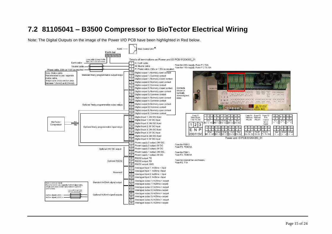
7.2 81105041 – B3500 Compressor to BioTector Electrical Wiring Note: The Digital Outputs on the image of the Power I//O PCB have been highlighted in Red below.
Page 16 of 24
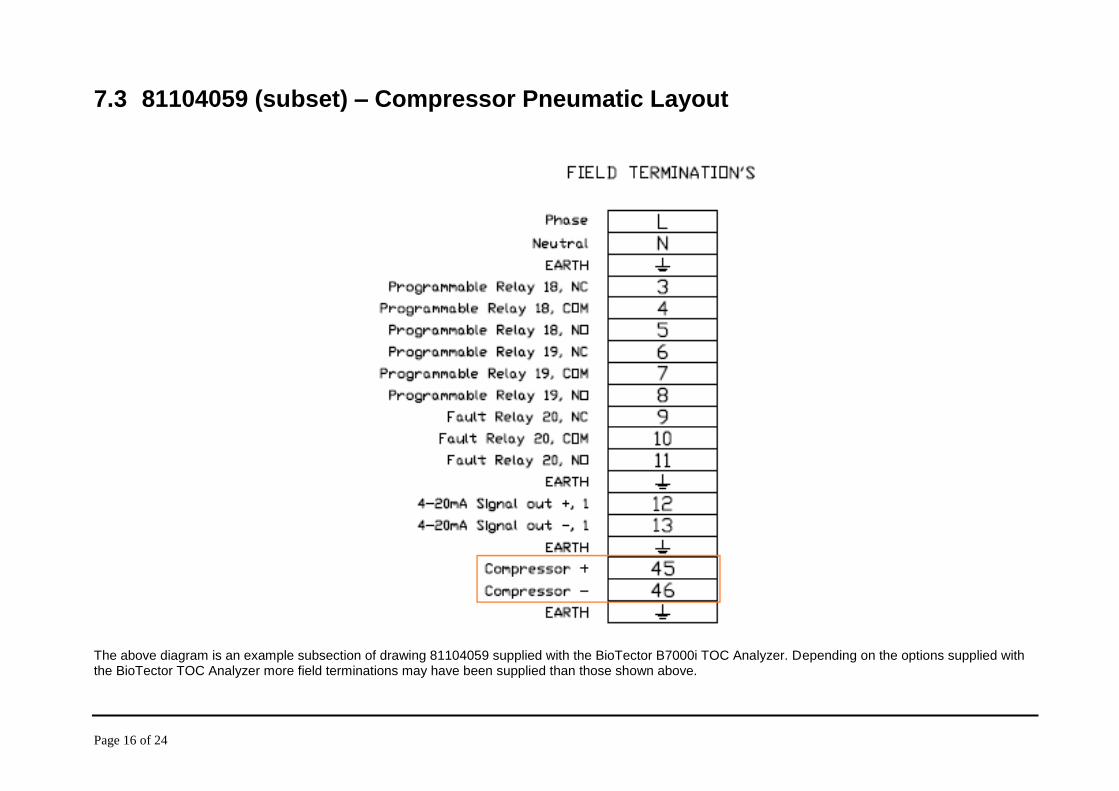
7.3 81104059 (subset) – Compressor Pneumatic Layout The above diagram is an example subsection of drawing 81104059 supplied with the BioTector B7000i TOC Analyzer. Depending on the options supplied with the BioTector TOC Analyzer more field terminations may have been supplied than those shown above.

Page 17 of 24
7.4 81101004 – Compressor Pneumatic Layout

Page 18 of 24
7.5 81805022 – B3500 Pneumatic Connection

Page 19 of 24
7.6 81804091 (subset) - B7000i Pneumatic Connection Note: The compressed air outlet on the BioTector Compressor is by default on the left hand side of the compressor enclosure. This compressed air outlet can be moved to the right hand side if the user wishes. See section 4. POSITION OF COMPRESSED AIR OUTLET ON COMPRESSOR. The side selected should allow for the shortest length of tube between the BioTector Compressor and the BioTector TOC Analyzer.
Page 20 of 24
8. SERVICE & MAINTENANCE Recommended check list for 6 month maintenance of the BioTector Compressor.
Replace the two 168mm filter mats in the fan and vent housing. These are accessible from the outside of the compressor housing on the left and right side (see item A in compressor service kit).
_____
Referring to example drawing 81101004 replace the following components:
Replace the filter cartridge inside of the Air Inlet Filter. Turn the filter head clockwise to remove (see item B in compressor service kit).
_____
Replace the filter cartridge inside of the Air Bleed Filter. Turn the filter head clockwise to remove (see item B in compressor service kit).
_____
Check and adjust the Compressor pressure if necessary:
The compressor outlet pressure may need to be adjusted. Using the BioTector
membrane keypad, go to Maintenance Diagnostics 02-CTRL Status menu. Once
this menu is displayed the compressor should turn ON automatically. AIR PRESSURE
SENSOR in this menu displays the current input pressure into the analyzer from the
compressor. To adjust this pressure the metal nut must be loosened on the Flow Valve
(10-SMC-011) in the Compressor enclosure. Refer to example drawing 81101004.
Adjust this valve to set the maximum output pressure from the compressor to 1200mbar
±100mbar. The output pressure will naturally fluctuate as the analyzer consumes the air.
After approximately two minutes confirm that a maximum pressure displayed is
1200mbar ±100mbar.
_____
Page 21 of 24
9. TROUBLESHOOTING Low Air Pressure:
- Go to the Operation Fault Archive menu on BioTector TOC Analyzer and confirm that there are no other faults related to the integrated oxygen concentrator.
- Looking at example drawing 81101004 above, check for possible air leak in the system. Remove the “Air Inlet Filter” and confirm it is not blocked.
- Readjust the “Flow Valve” by rotating the knob one revolution clockwise and check for any increase in the input air pressure to the analyzer. See section 5. COMMISSIONING AND STARTUP for further details.
- Fault or problem with the compressor unit. During normal operation, the temperature of the compressor head (the top section of the compressor) should be around 60°C on a compressor which has been running for at least 30 minutes. If the compressor temperature is significantly lower (e.g. 25°C), this indicates that the compressor does not generate pressure.
High Air Pressure:
- Go to Operation Fault Archive menu on BioTector and confirm that there are no other faults related to the integrated oxygen concentrator and the BioTector.
- Remove the “Air Bleed Filter” and confirm it is not blocked. See example drawing 81101004 above. - If necessary readjust “Flow Valve”. See section 5. COMMISSIONING AND STARTUP for details.
Compressor not Operating: Note: If checking the connections or fuses at the BioTector Compressor PCB inside the BioTector Compressor enclosure ensure section 6.2 DEACTIVATE AND ISOLATE THE BIOTECTOR COMPRESSOR is followed first.
- Ensure power is being supplied to the BioTector Compressor and the disconnection switch outside the BioTector Compressor is at the ON position.
- When the power is supplied to the BioTector Compressor the LED D1 one the BioTector Compressor PCB lights up. Otherwise, check the supply cable to ensure the power is coming from the mains socket.
- Ensure the wiring to the BioTector TOC Analyzer is correct according to drawing 81105041. - Ensure that when the BioTector Compressor output in The BioTector Analyzer is activated the LED
D4 on the BioTector Compressor PCB lights up - Ensure that when the LED D1 and D4 on the BioTector Compressor PCB lights up the Fan and the
Compressor outputs are activated by checking LED’s D2 and D3 - lights up when activated - when the LED D1 and D4 on the BioTector Compressor PCB lights up and the LED D2 and/or D3
doesn’t lights up fuse may be blown, check fuses referencing drawing 81101005 and replace if necessary.
- Ensure no other faults are occurring on the BioTector TOC Analyzer which may be restricting the START signal being sent to the BioTector Compressor.

Page 22 of 24
10. BIOTECTOR COMPRESSOR SYSTEM REPLACEMENT AND SPARE PARTS LIST
Item Order Code Description Quantity
Service Kit 19-KIT-126 Compressor Service Kit - 6 Month 1
Compressor PCB 115V 19-PCB-048 115V Compressor Controller PCB 1
Compressor PCB 230V 19-PCB-049 230V Compressor Controller PCB 1
Compressor Unit 230V 10-ASF-016 230V Piston Compressor Complete with 4 anti-vibration mounts
1
Compressor Unit 115V 10-ASF-018 115V Piston Compressor Complete with 4 anti-vibration mounts
1
Fan & Filter 115V 10-RTL-016 Compressor Fan & Filter unit, 115V 50/60 105 m³/h, RAL 7035, 204mm
1
Fan & Filter 230V 10-RTL-012 Compressor Fan & Filter unit, 230V 50/60 105 m³/h, RAL 7035, 204mm
1

23rd June 2016
DOC012.97.80506
User Guidance for EMC Class A
Equipment
업무용을 위한 EMC 등급 A 장치에 대한
사용자 지침
사용자안내문
A 급 기기 (업무용 방송통신기자재) 이 기기는 업무용(A 급)
전자파적합기기로서 판매자 또는 사용자는 이 점을
주의하시기 바라며, 가정외의 지역에서 사용하는 것을
목적으로 합니다.

This document contains information which is only required for the export of this instrument into
the People’s Republic of China.
本手册只包含出口到中华人民共和国的仪器的必要信息。
Statement on China "Management Methods for the Restriction of the Use of Hazardous
Substances in Electrical and Electronic Products”, Ministry of Information Industry Order #39.
(China RoHS2)
中国信息产业部 39 号指令“限制在电子电气产品中使用有害物质管理办法”的声明(China
RoHS2)
Toxic or Hazardous Substances and Elements controlled by China RoHS:
中国电子电气产品中使用有害物质指令限制的有毒有害物质:
铅 - Pb - Lead,
汞 - Hg - Mercury
镉 - Cd – Cadmium
六价铬 - Cr+6 - Hexavalent Chromium
多溴联苯 - PBB - Polybrominated Biphenyl
多溴二苯醚 - PBDE - Polybrominated Diphenylether
(Ref: Chinese Ministry of Information Industry Order #39)
(参考:中国信息产业部第 39 号指令)
We declare this product does not contain any of the six restricted substances above the
allowable limits. The product manufacturing date can be found on the product type
label.
特此声明此产品中以上六种受限物质的含量并未超过限制。产品生产日期注明于
产品类型标签中。


