SELECTING A LOCATION ...................................................................................................................................... 9
POWER REQUIREMENTS ..................................................................................................................................... 9
MAKING CONNECTIONS ...................................................................................................................................... 9
Power .............................................................................................................................................................. 9
INITIAL POWER UP ............................................................................................................................................ 17
SOLAR ON LED ................................................................................................................................................... 17
SOLAR OFF LED .................................................................................................................................................. 17
AC IN LED ........................................................................................................................................................... 17
VOICE SYSTEM ................................................................................................................................................... 17
FUNCTIONAL TEST ............................................................................................................................................. 18
PREPARING FOR RETURN SHIPMENT ........................................................................................... 21
MidNite Solar MNBirdhouse User Manual - Rev J 4-2-15
3 | P a g e
IMPORTANT SAFETY INSTRUCTIONS
SAVE THESE INSTRUCTIONS - These instructions contain important safety and operating instructions
for the MidNite Solar MNBH Disconnecting Panel that shall be followed during installation and maintenance of the power system. If you do not fully understand any of the concepts, terminology, or hazards outlined in these instructions, please refer installation to a qualified dealer, electrician or installer. These instructions are not meant to be a complete explanation of a renewable energy system.
GENERAL PRECAUTIONS
If service or repair should become necessary, contact MidNite Solar Inc. Improper servicing may result in a risk of shock, fire or explosion. To reduce these risks, disconnect all wiring before attempting any maintenance or cleaning. Turning off the inverter will not reduce these risks. Solar modules produce power when exposed to light. When it is not possible to disconnect the power coming from the Photovoltaics by an external means such as a combiner, cover the modules with an opaque material before servicing any connected equipment. Do not work alone. Someone should be in the range of your voice or close enough to come to your aid when you work with or near electrical equipment. Remove rings, bracelets, necklaces, watches etc. when working with photovoltaic modules or other electrical equipment. Power from an illuminated photovoltaic array makes a very effective arc welder with dire consequences if one of the welded pieces is on your person.
INSTRUCTIONS DE SECURITÉ IMPORTANTES
CONSERVER CES INSTRUCTIONS - Ces instructions contiennent des informations importantes pour utiliser le Midnite Solar MNBH panneau de déconnexion en toute sécurité. Il faut qu’on les suivre dans l’installation et entretien de cet appareil.
Avant l’utilisez cet appareil lis et comprends toutes les instructions et avertissements. Si vous ne comprenez pas l’une des concepts ou des instructions contenu dans cette manuel consulter un agent spécialisé. Si des réparations sont nécessaires contactez MidNite Solar pour plus des informations. Danger de choc électrique et de risque de brulure. Rien à dépanner à l'intérieure du cette appareil. Ne pas ouvrir le couver. Pour toute réparation ou service d'entretien, consulter un agent spécialisé. Il y’a peut-être plusieurs sources d’alimentation dans cette system. Débrancher toutes les interrupteurs avant toute d'entretien où nettoyage. Ne travaillez pas seul. Quelqu'un devrait toujours être à proximité pour vous aider en cas d'une situation d'urgence. Retirer bagues, bracelets, colliers, montres, et quelles choses comme ça. Il y’a risque des blessures graves s’il y’a un court-circuit. Cela pourrait ruiner votre journée. Le câblage doit être fait en conformité avec le National Electrical Code ANSI / NFPA 70. Utiliser des méthodes de câblage de catégorie 1 pour les connexions de câblage sur .des terminaux d'un circuit de classe 2. Utilisez uniquement des fils de AWM de calibre 14-1/0. Sélectionnez le type de câble utilisé sur la base de la protection prévue par les disjoncteurs / fusibles. -. Merci pour avoir achetè des produits de MidNite Solar.
MidNite Solar MNBirdhouse User Manual - Rev J 4-2-15
4 | P a g e
SAFETY WARNINGS used throughout this document are as follows:
WARNING !
Warnings identify conditions or practices that could result in personal injury or loss of life.
CAUTION !
Cautions identify conditions or practices that could result in damage to the unit or other equipment.
MNBIRDHOUSE INSTALLATION GUIDELINES AND SAFETY INSTRUCTIONS
The following important restrictions apply unless superseded by local or national codes:
For routine, user-approved maintenance:
Turn off all circuit breakers, including those to the solar modules, batteries and related electrical connections
before performing any maintenance.
Standards and Requirements
All installations must comply with national and local electrical codes. Professional installation is recommended.
Wiring must be done in accordance with the National Electrical Code ANSI/NFPA 70. Use Class 1 wiring
methods for field wiring connections to terminals of a Class 2 circuit. Use only 14 gauge AWM wire. Select the
wire gauge used based on the protection provided by the circuit breakers/fuses.
This manual provides safety guidelines and installation information for the MNBirdhouse Disconnect Panel. It
describes in general terms how the Birdhouse connects to and controls MidNite Solar disconnecting
combiners, shut-off boxes, and the Battery Disconnect Module, but does not give details on combiner
installation or connections to equipment other than the Birdhouse. Refer to the MidNite Solar Disconnecting
Combiner User’s Manual for details on installing your specific combiner.
This manual does not provide brand specific information about other components in the system such as
photovoltaic panels, batteries, inverters, etc. Contact the manufacturer of all other components in the system
for relevant technical data.
Maximum open circuit voltage, and Maximum short circuit current for Photovoltaic modules must be
calculated using the manufacturers published ratings, temperature coefficients and the expected local
irradiance which will be present in the end use installation.
MidNite Solar MNBirdhouse User Manual - Rev J 4-2-15
5 | P a g e
SPECIFICATIONS
Power: 120/240 volt 50-60Hz AC power from a (recommended dedicated) circuit.
Connector accepts up to AWG #14 wire. Chassis lug for safety ground wire.
Solar Power: +48 volts DC (20mA nominal) from the DiscoPSB current limited (145mA max).
Remote Trip Input: Normally Open (N.O.) switch closure to GND. Internally pulled to +48 VDC when
inactive. Do not connect to a DC voltage. Interface using a relay.
Aux Relay Output: 1 form C relay contacts: Rated 1A @ 120VAC / 24 VDC
Batteries: 9 volt, rechargeable, NiMH, 180mAh or greater, Varta P/N 5122 V7/8H or equiv.
(Qty=4)
3.0 volt, lithium coin-cell, CR1216 (Qty=1)
Display LEDs: Solar ON – Green
Solar OFF – Amber
AC In – Green
Battery Low – Red
Environmental: Temperature
-40C to +85C (exclusive of batteries)
-40C to +65C (in storage with batteries installed – less than 30 days)
-20C to +65C (operating)
0C to +65C (batteries charging)
Weight: 4 lb 8oz. (2.05kg)
Enclosure: Type 3R RainProof
Symbols used in this manual
Equipment Ground
Direct Current Supply
On / Off Phase Symbol
Alternating Current Supply
MidNite Solar MNBirdhouse User Manual - Rev J 4-2-15
6 | P a g e
INTRODUCTION The MidNite Solar Birdhouse is a firefighter / service technician’s control device designed for disconnecting rooftop photovoltaic (PV) panels, batteries and inverters with their inherently hazardous voltages from the building wiring in case of emergencies or system maintenance. The Birdhouse works in conjunction with MidNite Solar disconnecting combiners with a DiscoPSB installed, MidNite Shut-off boxes, and Battery Disconnect Modules to provide the ability to disconnect power at the voltage source before sending personnel into the building or onto the roof. Disconnecting power requires the simple press of a single button. The panel’s LED display gives system status and an automated speech synthesis system gives further situation specific instructions.
DESCRIPTION The Birdhouse is housed in an attractive weather resistant enclosure designed for mounting near rooftop access points such as doors and ladders, however it may be mounted at any location up to 500 meters from the disconnecting enclosure. There can also be up to three additional Birdhouse units to provide PV disconnect capability in other areas of the building, as required by the installation. The Birdhouse has four LEDs which show the current state of the system and features a large push button inside of a magnetically latched access door. Reflective side labels clearly identify the Birdhouse panel as the Rapid System Shutdown point. Simply open and press the big red button to disconnect power at all the disconnect devices connected to the system. The Birdhouse also features a voice announcement system that audibly gives the appropriate instructions to remind personnel in the area that there may still be voltages present near the PV panels and to use caution. Internal rechargeable batteries provide temporary backup power in case of external power cutoff or failure. The Birdhouse also has a remote trip input and a software activated relay to allow the unit to be interfaced to other equipment such as an alarm system.
THEORY of OPERATION The heart of the system is the disconnecting combiner or shut-off box which feature an electrically trippable disconnect switch, to cut the power internally when triggered by a low voltage control signal. When the button at the Birdhouse is pressed, a trigger signal is sent to the DiscoPSB (disconnecting power supply board), which causes the disconnect switch to open, breaking the connection between the PV buss bar and the DC power wiring exiting the combiner. The connection between the buss bar and the DC power wiring exiting the enclosure is broken. Power will be off beyond the combiner or shut-off box. However, during the day voltage will still be present from the PV panels up to that location. The low voltage trip signal from the Birdhouse is supplied via a 600 volt rated CAT-5 cable from the combiner or shut-off box to Birdhouse units, typically at ground level. Power for tripping the disconnect switch is stored in a long life electrolytic capacitor on the DiscoPSB. The capacitor is oversized to be able to store enough energy to trip the disconnect switch numerous times without recharging, even after years of service. In normal operation the capacitor is kept charged by solar power. Backup circuits in the Birdhouse monitor the capacitor voltage and recharge it as needed during times of darkness or whenever power is removed, such as for maintenance. The system is designed to fail safely so that if all power fails or if any cable becomes damaged or unplugged the trip sense circuit on the DiscoPSB will trip the disconnect switch. As well as monitoring the combiner capacitor voltage, the Birdhouse monitors the disconnect switch position
and Disco PSB output voltage. Once the Birdhouse has sent the trip signal to the DiscoPSB, it continues to
monitor the disconnect switch's position and updates the LED status when the disconnect switch is known to
be open. If the button is pressed and the green LED goes off and the amber LED comes on, you can be assured
that the disconnect switch has opened. The audio system will play a message that the solar system has been
shut off. A second message is provided for the unlikely event that the disconnect switch does not open or is
MidNite Solar MNBirdhouse User Manual - Rev J 4-2-15
7 | P a g e
slow responding. Software will detect this condition and the voice will say that the solar system was not shut
off.
SYSTEM DESIGN Safe, reliable and efficient operation of the rapid shutoff system depends on proper system design. The
shutoff system components have been designed for flexibility in interconnecting to other devices as needed
for a particular installation. There are a few considerations to keep in mind as follow.
See System Layout Diagram (page 8)
1. The MNBirdhouse (Birdhouse), MNBDM (Battery Disconnect Module) and MNDiscoPSB (Combiners and
Shut-off boxes) should always be connected in a linear string (NO loops). This ensures fail safe operation in
the event that a cable becomes damaged or unplugged.
2. Do NOT install trippable devices between individual Birdhouses. All Birdhouses must be together on one
end of the string. Disco Power Supply Boards (Disconnecting Combiners, Shut-off boxes), and MNBDMs
may be intermixed, if needed.
3. All Birdhouse panels should be wired on a dedicated 120/240VAC circuit, if possible. The power is
negligible however the AC connector will accept up to #14 wire, typical for a 15A branch circuit.
4. The simplest system consists of a single Birdhouse and a single disconnect enclosure. MNBDM devices are
optional.
5. Battery based systems typically need to disconnect batteries and inverters as well as rooftop PV panels.
The MNBDM controllers can be used for shutting off other circuits by interfacing a shunt-trip circuit
breaker to your load. The only caveat is that the MNBDM needs a 24-48 volt DC power source, which is
not provided by the Birdhouse. Refer to the MNBDM documentation for details.
6. The External Trigger input may be used to shut down the system from another device, such as an alarm
system. It is designed to be interfaced to a normally open switch. This is a logic signal input. No
significant current or power is involved. Do not connect the External Trigger to a DC voltage. Instead use
your voltage source to activate a small normally open relay.
7. The AUX relay is a low current 1 form C relay for controlling other devices. See the description in the
"MAKING CONNECTIONS" section.
8. This product is intended for operation in an environment having a maximum ambient temperature of 65°C.
MidNite Solar MNBirdhouse User Manual - Rev J 4-2-15
8 | P a g e
EXTERNAL
TRIGGER
(Alarm System, etc)
AC
Neutral
Safety
GND
AC
Hot
Combiner
MNBDM 1
MNBDM 2
COM
N.O.
N.C.
Primary
Birdhouse
Secondary
Birdhouse 1
Secondary
Birdhouse 2
High voltage UV resistant cable
needed beyond this point
SYSTEM LAYOUT DIAGRAM
175
ONOFF
175
ONOFF
AUX
RELAY
OUT
175
ONOFF
175
ONOFF
Combiner
Inverter
Disconnect
...
PV Array
PV Array
Inverter
Disconnect
Inverter
Inverter
MidNite Solar MNBirdhouse User Manual - Rev J 4-2-15
9 | P a g e
INSTALLATION
SELECTING A LOCATION NOTE: The MNBirdhouse panel must be located and wired in compliance with local and national codes. The
following instructions are typical in nature. Details may vary. Professional installation is recommended.
Attention -The system status indicator shall be installed in a location in close proximity to the system
actuator, where the indication of shutdown can be clearly seen.
In general, the Birdhouse should be located in a readily accessible location either on the outside of the building
or structure, or inside nearest the point of entrance of the system conductors. Additional panels might be
located near roof access doors or ladders and one might be located at the central solar control point such as
the inverter, charge controller or battery cabinet. Allow some space around the BirdHouse for ventilation.
The Birdhouse closest to the disconnect switch should be the one chosen for the cable connection to the
switch. This first Birdhouse is referred to as the primary unit. Any others are referred to as secondary units.
Up to three secondary units can be wired to the primary unit, as appropriate.
See System Layout Diagram (page 8)
POWER REQUIREMENTS Each Birdhouse requires an AC power connection. It is recommended all Birdhouses be powered by a
dedicated branch circuit. The wiring should be enclosed in conduit and installed in accordance with local
codes. An internal box lug is provided for the safety ground.
MOUNTING Mount the Birdhouse to the wall in the desired location. No brackets or mounting plate is necessary.
Waterproof sealant is recommended on the four mounting screw locations. Electrical connections are made to
the building wiring and external equipment using screw-terminal connectors along the bottom edge of the
main board. Connections to the Disco Power supply board, the MNBDM and additional Birdhouse panels are
made via the RJ-45 (Ethernet-style) jacks. Cables and other wiring can be pulled to the Birdhouse through
standard thin wall conduit. Knockouts in the chassis support backside or bottom cable entry.
MAKING CONNECTIONS The field-wiring terminals shall be connected using the following wire types: Copper and copper clad Conductors Only - Use 90°C copper wire. For conduit hubs, use only UL Listed raintight, or wet location hubs for entry into the enclosure” The UL Listing of the Rapid Shutdown Controller model MNBH requires that the CAT-5 conductor torque and outputs must be connected only to the MidNite Solar approved Power Supply Board.
Power
The Birdhouse requires a nominal 120 volt AC connection to the building wiring and a cable connection to the
DiscoPSB. Connect the AC hot wire (typically black or red) to TB3 pin 1. Connect the AC Neutral (white) to TB3
Pin 2. Connect the safety ground (green) to the chassis box lug below the main board.
MidNite Solar MNBirdhouse User Manual - Rev J 4-2-15
10 | P a g e
Remote Trip Input
An optional remote trip input is provided to interface an alarm output from other devices such as fire alarm systems, door interlocks and security systems to the Birdhouse. All that is required is a simple (normally open) disconnect switch closure, such as a relay. Connect the controlling device’s switch wires to TB5 pins 1&2. If no remote trip input is needed leave the remote trip pins disconnected. Note that TB5 pin 1 is connected to the logic GND and may be used as a reference for voltage measurements for Birdhouse control signals, however it is not connected to earth ground.
Combiner and Secondary MNBN Panels
There are two Ethernet-style RJ-45 jacks on the Birdhouse main board. These are not network connectors.
These connectors carry low-voltage, signals, power and voltage sensing leads to monitor and trip the
disconnecting switch and other equipment. These connectors are only for interfacing other MidNite Solar
equipment such as disconnecting combiners, shut-off boxes, other Birdhouses, and MNBDM controllers. They are
wired identically. Either connector may be used for the cable run to the disconnect. The other is available for
connection to additional Birdhouses, if needed. This feature allows up to three additional Birdhouse panels to be
connected to a single disconnect in a series string. The cables are straight through cables (not crossover) and are
wired according to the T568B standard. The cable connecting secondary Birdhouse panels to the primary Birdhouse
panel, or to each other can be any (low voltage) CAT-5 cable that meets local code. However, because of the high
voltages inside the combiner or shut-off box, the CAT-5 cable that connects the primary Birdhouse to the combiner
or shut-off must be rated for 600 volts and be UV rated for weather and sun exposure.
See System Layout Diagram (page 8)
MidNite Solar or your installer can provide more information on cable requirements It is recommended that only genuine Molex RJ-45 plugs (Molex p/n 44915-0001) be used to terminate MidNite Solar's ruggedized 600 volt CAT-5 cable. While all CAT-5 plugs look similar and generally fit the receptacles, there are important differences in the copper diameter and insulation thickness they are designed to be used with which effects how well they crimp the wire, plus the overall quality of retail parts can be inferior. Avoid purchasing similar looking connectors from hardware stores or electrical suppliers unless you have tested them and are certain that they work properly. The wrong connector can be very difficult to assemble properly and may become intermittent. The proper connectors are available from MidNite solar (p/n 9-497-1).
Right: TIA/EIA 568B CAT-5 Ethernet cable end connections.
General cable crimping instructions. 1. Cut cable to length and strip 0.9" of the outer jacket at each end. 2. Strip 0.5" of the inner jacket at each end. 3. Place 2 - 0.50" pieces of heatshrink on cable. 4. Arrange wires and push fully into connector. 5. Crimp connector at each end. 6. Perform functional test. 7. Shrink heatshrink in place at ends.
Completed cable ends.
MidNite Solar MNBirdhouse User Manual - Rev J 4-2-15
11 | P a g e
Important! A small packet of silicone gel is included with the BirdHouse. This is used to protect the connectors on the CAT-5 cable. Only use a gel intended for protecting electrical connections of this type such as the gel that
ships with the BirdHouse. Other types may interfere with the connections and may damage
the board or and/or cable.
Tear off the tip of the packet at the notch and squeeze out some gel. You will want to get a good amount of gel in the connection. You can put some inside the connector on the board and some on the connecter at the end of the cable as well. It does not need to be oozing out, just so that the connections are thoroughly coated. Without the protective gel the connecters can corrode leading to failure of the system.
Aux Relay Output
The Aux Relay is active whenever the Birdhouse is in Alarm mode. Alarm mode is an internal state that begins when
the button is pressed while the disconnect switch is closed and ends when the switch is closed again after having
opened.
NOTE: The amber Solar Off LED corresponds to the state of the PV system regardless of how the disconnect
switch was opened. Shutting off the power manually at the disconnect illuminates the Solar Off LED but does not
cause the Birdhouse panel to go to Alarm mode, so the Aux Relay will not activate. In other words the AUX relay
only activates when the Rapid System Shutdown process was performed in response to pressing the red button.
INSTALLATION PROCEDURE 1. Unpack the Unit. Inspect for damage.
2. Open the MNBirdhouse panel’s large door and remove the six #8 flat head Philips screws holding the case
on. Carefully remove the case and place it in a safe location so it will not be damaged.
3. Test the unit by TEMPORARILY installing battery shunt CON4, located near the right edge of the main
circuit board . The SOLAR ON/OFF and the BATTERY LOW LEDs should flash. After several seconds the
voice system should say, “Please wait. Self-test in progress.” If this test fails the batteries may be
completely discharged. Batteries that have been discharged for a long time may be permanently damaged
and should not be placed into service. While good batteries will charge from line power, it is
recommended that all batteries be fully charged before putting the system into service. Use a good quality
“smart” charger such as the Tenergy model TN346. Avoid inexpensive “timer” based chargers. If the unit
does not operate with fully charged batteries call MidNite Solar’s technical support for assistance.
To Open: Tear here.
Apply silicone gel to
these connectors
MidNite Solar MNBirdhouse User Manual - Rev J 4-2-15
12 | P a g e
4. REMOVE the shunt from CON4 and place it in the shipping position until the entire installation procedure is
completed to conserve battery power.
Shipping Position
Place jumper on only one pin to disconnect battery from circuit.
Place jumper on both pins for normal operation.
MidNite Solar MNBirdhouse User Manual - Rev J 4-2-15
13 | P a g e
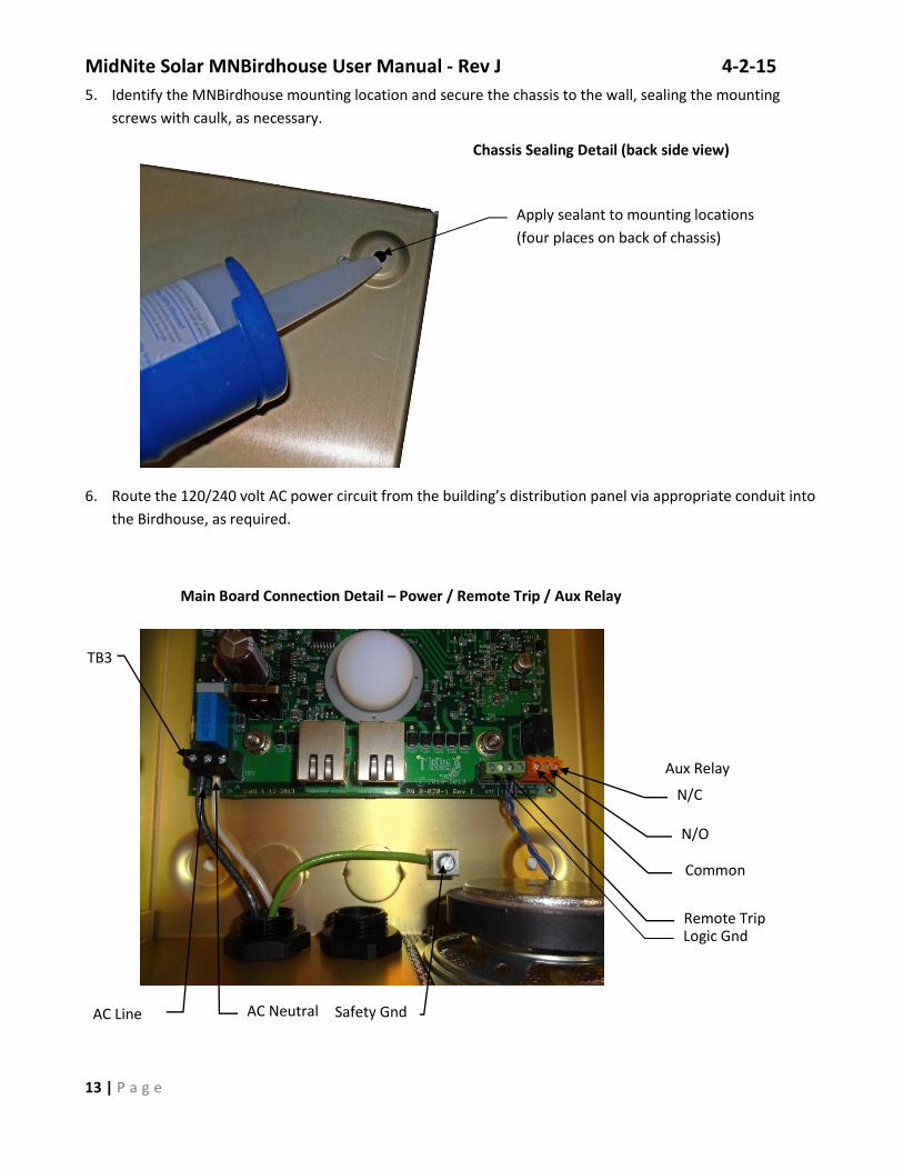
5. Identify the MNBirdhouse mounting location and secure the chassis to the wall, sealing the mounting
screws with caulk, as necessary.
6. Route the 120/240 volt AC power circuit from the building’s distribution panel via appropriate conduit into
the Birdhouse, as required.
AC Line
Remote Trip
Aux Relay
Apply sealant to mounting locations
(four places on back of chassis)
Main Board Connection Detail – Power / Remote Trip / Aux Relay
Chassis Sealing Detail (back side view)
AC Neutral Safety Gnd
Common
COMMON
N/O
N/C
Logic Gnd
TB3
MidNite Solar MNBirdhouse User Manual - Rev J 4-2-15
14 | P a g e
Connect the line side (black or red) of the 120/240 volt AC power to TB3 pin 1. Connect the neutral
side (white) to TB3 pin 2. Connect the safety ground (green) to the chassis box lug located below the
main circuit board. TB3 pin 3 pin 3 on the PCB is also a chassis ground connection (shown open).
7. Connect the 600 volt UV rated CAT-5 control cable to the disconnect at J1. Use a small amount of silicone
grease on all cable ends to protect the connections and repel moisture.
8. In a similar manner, connect the CAT-5 cable from any other Birdhouse unit(s) to J2.
9. Connect the optional remote trip output from any other equipment such as alarm or fire detection
systems to the Birdhouse panel’s Remote Trip input at TB5 pins 1&2. If either of the wires coming from the
external equipment is grounded, connect that wire to TB5 pin 1. The input is designed for a switch closure
to GND. Do NOT connect the Remote Trip input to a DC source.
10. Optionally, connect the alarm input of any other equipment such as an alarm system the Birdhouse AUX
relay output connector, TB4. The common is pin 1, the normally open contact is pin 2, and the normally
closed contact is pin 3. The AUX relay provides a set of isolated 1 form C contacts and may be used to
switch low voltage control signals (28V @1A), as needed.
11. When installation is complete and the system is ready to be energized, remove the small plastic battery
isolator from battery holder BH1, located at the upper right corner of the main logic board.
12. Install battery shunt CON4. (Refer to step 3.) Replace the case and test the system. Apply caulk sealant to
the case to wall interface along the top edge of the case especially if the wall is not smooth such as lap siding
or corrugated metal.
J1 - In from disconnect or
secondary Birdhouse(s)
J2 - Out to secondary
Birdhouse(s)
Main Board Connection Detail – Disconnect and Secondary MNBirdhouse Panel Connections
Remove plastic
isolator
TB3
Battery Holder BH1 Detail
MidNite Solar MNBirdhouse User Manual - Rev J 4-2-15
15 | P a g e
MidNite Solar MNBirdhouse User Manual - Rev J 4-2-15
16 | P a g e
12.
Sealing the MNBirdhouse Enclosure to Exterior Wall
Inside view of a Birdhouse that wasn’t sealed against the elements. The snow went through gaps in back from an uneven mounting surface (like most siding). When this snow melts it could drip down inside causing problems.
The PCB area of that same Birdhouse. The fine powdery snow had no trouble finding its way in through the unsealed edges. Some of the mounting holes were left unused providing more access to insects and the elements. The battery insulator tab was not removed either. Careful installation can save a lot of problems later.
On an uneven surface it is recommended to mount a flat panel to the wall and mount the Birdhouse on the flat panel.
Don’t Do This!
MidNite Solar MNBirdhouse User Manual - Rev J 4-2-15
17 | P a g e
OPERATION
INITIAL POWER UP The AC IN LED should come on immediately when the unit is powered up. The SOLAR ON and SOLAR off LEDs
immediately reflect the state of the disconnect switch(es). The first time the system is powered up the
Birdhouse should find that it needs to charge the Disco power supply capacitors. After a couple minutes the
capacitors will have reached full charge and the voice announcement will say, "The System is Ready." This
verifies the cable integrity and voltage feedback from the Disco power supply capacitor.
SOLAR ON LED The green LED on the left indicates that the disconnect switch is closed. If there is any sunlight present, high
voltages will be present throughout the system.
SOLAR OFF LED The amber LED indicates that the disconnect switch is open. In daytime there will still be hazardous voltages
present on the PV string wiring up to the combiner or shut-off box. If the power was disconnected by pressing
the button at the Birdhosue, the red handle will still be in the ON position but the power is shut off internally.
AC IN LED The green AC IN LED indicates that local AC power is on. In normal operation this LED should be ON.
LOW BATTERY LED The Birdhouse’s internal batteries are continually monitored and recharged automatically as needed. The
LOW BATTERY LED indicates that the batteries have discharged to an unacceptably low level and in normal
operation should be off. If external power has been off for several hours the LOW BATTERY LED may come on.
In this case it may remain on for a while after power is restored, but it typically will not remain on longer than
20 minutes. If the LOW BATTERY LED comes on unexpectedly or remains on for a long time after restoring AC
power, a problem may exist with the batteries or charging circuits. The unit should be inspected and repaired
as necessary.
VOICE SYSTEM When the Birdhouse completes its self test it will detect the disconnect switch. Once the Disco power supply
capacitor is fully charged the voice system will say, “The system is ready.” Note that if there is no initial charge
on the capacitor this may take a few minutes. Thereafter, the voice system will speak only when the button is
pressed, the disconnect switch is closed, or a problem is detected with the system that requires attention.
When the button is pressed software waits for the position feedback signal from disconnect switch and
MNBDM controllers to be received. When it senses that all switches have opened the voice system
announces, "Rapid System Shutdown Initiated. All Normally Energized Portions of the Solar System Should
Now Be Off. Treat All Solar Panels as Live. Treat all Wiring With Caution." This announcement repeats at
one minute intervals until the disconnect switch is closed, or the announcement is cancelled by the user. To
cancel the voice announcement at the Birdhouse, press and hold the red button for five seconds.
In the unlikely event that the disconnect switch does not open, (due to ice, corrosion, damage, etc.) the
feedback monitoring software will NOT detect a change in switch position. After several seconds the voice
MidNite Solar MNBirdhouse User Manual - Rev J 4-2-15
18 | P a g e
system will give the message, "WARNING. The Solar System Was Not Switched Off," three times. The message
will be repeated on one minute intervals until either the switch is opened or the announcement is cancelled by
the user.
OPTIONAL GOOD MORNING MESSAGE
The Birdhouse Voice System has an optional message that sounds like a rooster crowing each morning when
the solar panels begin to produce power. This feature is provided to ensure users that the system is operating
and is in normal power production mode. This feature is disabled when shipped and may be enabled or
(disabled if enabled) as follows:
1. When in the normal operating mode, press the red button at the Birdhouse to disconnect solar power
at the combiner or shut-off box.
2. When the voice message finishes, press and hold the red button five seconds to cancel any further
announcements. The disconnect switch will be open.
3. After the “Voice Announcement is Off” message, press the button three times within two seconds to
toggle the state of the “Good Morning” message. An acknowledgement is played if successful. If the
“The solar system has been switched off” message plays, you have missed the two second window or
have not pressed the button the correct number of times.
4. Repeat steps 2 and 3 for each Birdhouse in the system then close each disconnect switch by turning
the red handle fully off and back on. The Birdhouse setting will be retained as long as the units have
power. If all power is lost the option will revert to disabled.
FUNCTIONAL TEST The Rapid Shutoff System must be tested periodically. It is recommended test the system upon first
commissioning the, when restoring power after rapid shutdown initiation, or at minimum annually.
Note: AC IN LED must be on when starting up or testing the solar system. The on board batteries are intended to keep the system up during temporary AC interruptions only.
1. When the solar system is off verify that the SOLAR OFF LED is ON at each MNBH panel.
2. Turn MNBDM connected battery breakers on first, then turn on combiners and shut off boxes. Verify
that the SOLAR ON LED comes ON at each MNBH panel and that the voice system says, "The Solar
System has Been Switched On."
3. When the voice system says, "The System is ready." press the red shutdown button. If the SOLAR ON
LED goes off and the SOLAR OFF LED comes on the system is operational. The voice system should say,
" Rapid System Shutdown Initiated. All Normally Energized Portions of the Solar System Should Now
Be Off. Treat All Solar Panels as Live. Treat all Wiring With Caution".
4. Repeat steps 1 and 2 to turn on the system.
MidNite Solar MNBirdhouse User Manual - Rev J 4-2-15
19 | P a g e
MAINTENANCE
CAUTION!
Nickel-Metal Hydride batteries produce high currents when short circuited.
Follow the instructions carefully to avoid damage to the batteries or unit.
BATTERIES There are four rechargeable 9-volt Nickel Metal Hydride (Ni-MH) batteries in the Birdhouse. They are found on
the LED-Battery board (P/N 8-026-10), located inside the unit at the top of the main logic board. There is also
a 3.3-volt lithium coin-cell battery located on the main logic board at the top right corner below CON2.
The 9-volt batteries are series connected to form a 36-volt battery. Together they serve as a backup power
source for the Birdhouse in case of power failure or disconnection of the AC grid. They were included in the
Birdhouse design for triple redundancy to assure that the disconnect switch trip capacitor on the DiscoPSB will
always be kept charged. These batteries operate the Birdhouse logic and supply reserve power to recharge
the disconnect switch trip capacitor. In normal operation the batteries are kept charged by solar power in the
daytime and from the AC/DC power source at the Birdhouse at other times. The only time the batteries
actually supply power the unit is when no other power is available.
If all external power is removed and there is no emergency, (i.e. - the Birdhouse voice system is not operating),
the batteries will power the unit for up to 16 hours depending upon the temperature, battery age and the
initial charge of the batteries. If there is an emergency situation and voice messages are playing the batteries
life will be shorter because of higher current demand. They will recharge automatically when external power
is restored.
The coin cell battery, B1, allows the Birdhouse’s internal microprocessor to keep track of time and go into low
power mode to conserve batteries in the rare event of a complete power failure. In normal operation there is
no current drawn from the coin-cell battery. It should last 5 years or more. However, since it is a low cost
component it is recommended that the coin-cell battery be replaced at the same time as the 9-volt batteries.
MidNite Solar MNBirdhouse User Manual - Rev J 4-2-15
20 | P a g e
BATTERY REPLACEMENT PROCEDURE
CAUTION!
Nickel-Metal Hydride batteries produce high currents when short circuited.
Follow the procedure carefully to avoid damage to the unit.
1. IMPORTANT! All batteries should be replaced at the same time including the lithium coin-cell battery,
B1.
2. IMPORTANT! Batteries should be replaced at night or with the disconnect switch OPEN because power is
supplied by the Disco power supply during daylight. Otherwise you must disconnect the CAT-5 cables
going to the combiner or shut-off box, and any other Birdhouses.
3. IMPORTANT! Do NOT place the Battery-LED board on any electrically conductive surface or article such
as a tool while there are batteries installed on it. High SHORT CIRCUIT currents will flow!
4. IMPORTANT! Before proceeding, shut off AC power at the circuit breaker panel.
5. Open the Birdhouse panel’s large door and remove the six #8 flat head screws holding the case on.
Carefully remove the case and place it in a safe location so it will not be damaged.
6. IMPORTANT! Remove the shunt on CON4. See photo in the Installation section.
7. Remove the two screws holding the Battery-LED board to the top of the unit. Remove the board being
careful not to damage the LEDs.
8. Carefully slice through the silicone sealant holding the batteries to the circuit board or cut the tie-wraps
and remove the old batteries. Dispose of the used batteries properly.
Battery – LED Board detail.
MidNite Solar MNBirdhouse User Manual - Rev J 4-2-15
21 | P a g e
9. Replace all four 9-volt batteries with new, fully charged NiMH batteries. Since the battery connectors
cannot be conformal coated they are a potential point of corrosion. Using a small amount of silicone
grease on the battery terminals is recommended.
10. Secure the batteries to the board. Holes for tie-wraps are provided but electrical tape also works well.
11. Replace the 3-volt lithium coin-cell battery, B1, before reinstalling the Battery-LED board. There’s more
room to work around the area of the battery with the Battery - LED board removed.
12. Re-install the Battery - LED board.
13. Re-install the shunt on JP1. The voice system should say, “Self-Test is in progress.” And the LEDs should
reflect the current state of the disconnect switch.
14. Restore AC power. The AC ON LED should come on.
15. Re-install the case.
16. Restore solar power and test the system. Reseal the case to wall interface with caulk as shown in the
detail on page 12.
PERIODIC INSPECTION While leakage and terminal corrosion is extremely rare with modern batteries, it is not impossible and may be
exacerbated by environmental conditions such as extreme heat, dust, moisture, or salty ocean air. Of course,
the main cause of battery leakage and corrosion is leaving them in a discharged state for a long time as well as
repeated overcharging, neither of which should ever happen if the unit is functioning properly. The red
BATTERY LOW LED will come on if the batteries are undercharged.
However, for security and peace of mind it is recommended that the Birdhouse panel cover be removed once
every 2 years for inspection especially the batteries and connectors on the Battery-LED board, particularly if
units are exposed to the elements.
PREPARING FOR RETURN SHIPMENT Prior to returning any product to the factory please contact MidNite Solar to obtain an RMA number and
receive shipping instructions.
IMPORTANT! To avoid any possibility of damage due to battery leakage or corrosion it is recommended that
used batteries be removed from the MNBH Disconnect Panel and not returned to MidNite Solar unless you are
instructed to do so by Customer Service. If you are instructed to do so, it is very important that you REMOVE
the battery shunt, CON4, on the main board. See CON4 detail photograph in Step 2 of the Installation
Procedure.
MidNite Solar MNBirdhouse User Manual - Rev J 4-2-15
22 | P a g e
MIDNITE SOLAR INC. LIMITED WARRANTY
MidNite Solar Power electronics, sheet metal enclosures and accessories
MidNite Solar Inc. warrants to the original customer that its products shall be free from defects in materials and workmanship. This warranty will be valid for a period of five (5) years on the MNBH Birdhouse and two (2) years on the included batteries. Please visit www.midnitesolar.com or contact MidNite Solar for further details. At its option, MidNite Solar will repair or replace at no charge any MidNite product that proves to be defective within such warranty period. This warranty shall not apply if the MidNite Solar product has been damaged by unreasonable use, accident, negligence, service or modification by anyone other than MidNite Solar, or by any other causes unrelated to materials and workmanship. The original consumer purchaser must retain original purchase receipt for proof of purchase as a condition precedent to warranty coverage. To receive in-warranty service, the defective product must be received no later than two (2) weeks after the end of the warranty period. The product must be accompanied by proof of purchase and Return Authorization (RA) number issued by MidNite Solar. For an RMA number contact MidNite Solar Inc., 17722 67th Ave NE, Arlington, WA 98223 (360) 403-7207. Purchasers must prepay all delivery costs or shipping charges to return any defective MidNite Solar product under this warranty policy. Except for the warranty that the products are made in accordance with, the specifications therefore supplied or agreed to by customer: MIDNITE SOLAR MAKES NO WARRANTY EXPRESSED OR IMPLIED, AND ANY IMPLIED WARRANTY OF MERCHANTABILITY OR FITNESS FOR A PARTICULAR PURPOSE WHICH EXCEEDS THE FOREGOING WARRANTY IS HEREBY DISCLAIMED BY MIDNITE SOLAR AND EXCLUDED FROM ANY AGREEMENT MADE BY ACCEPTANCE OF ANY ORDER PURSUANT TO THIS QUOTATION. MIDNITE SOLAR WILL NOT BE LIABLE FOR ANY CONSEQUENTIAL DAMAGES, LOSS OR EXPENSE ARISING IN CONNECTION WITH THE USE OF OR THE INABILITY TO USE ITS GOODS FOR ANY PURPOSE WHATSOEVER. MIDNITE SOLAR’S MAXIMUM LIABILITY SHALL NOT IN ANY CASE EXCEED THE CONTRACT PRICE FOR THE GOODS CLAIMED TO BE DEFECTIVE OR UNSUITABLE. Products will be considered accepted by customer unless written notice to the contrary is given to MidNite Solar within ten (10) days of such delivery to customer. MIDNITE SOLAR is not responsible for loss or damage to products owned by customer and located on MIDNITE SOLAR’S premises caused by fire or other casualties beyond MIDNITE SOLAR’s control. This warranty is in lieu of all other warranties expressed or implied. PH: 360.403-7207 FAX: 360-691-6862