2800 LAURA LANE / MIDDLETON, WI 53562 / (608) 836-9034 / FAX (608) 836-9044 / WEB SITE WWW.TCS-BASYS.COM R OA N.C. N.C. EA RA OA N.C. RA OA N.C. N.C. EA SPECIAL AHU1.bmp AHU2.bmp AHU3.bmp RA OA N.C. N.C. EA EVAPORATOR CONDENSOR Daniel T. Young V1.bmp V2.bmp V3.bmp FAN.bmp PUMP.bmp BOILER.bmp COMP.bmp CHILLER1.bmp CHILLER2.bmp TOWER1.bmp TOWER2.bmp BOX.bmp AHU4.bmp R1-a R Bitmaps
Transcript
2800 LAURA LANE / MIDDLETON, WI 53562 / (608) 836-9034 / FAX (608) 836-9044 / WEB SITE WWW.TCS-BASYS.COM
R
OA
N.C.
N.C.
EA
RA
OA
N.C.
RA
OA
N.C.
N.C.
EA
SPECIALAHU1.bmp
AHU2.bmp
AHU3.bmp
RA
OA
N.C.
N.C.
EA
Daniel T. Young
EVAPORATOR
CONDENSORDaniel T. Young
V1.bmp V2.bmp V3.bmp
FAN.bmp PUMP.bmpBOILER.bmp COMP.bmp
CHILLER1.bmp CHILLER2.bmp
TOWER1.bmp TOWER2.bmp
BOX.bmp
AHU4.bmp
R1-a
R
Bitmaps
2800 LAURA LANE / MIDDLETON, WI 53562 / (608) 836-9034 / FAX (608) 836-9044 / WEB SITE WWW.TCS-BASYS.COM
R
HEATPUMP.bmp SZ3001.bmp
HPLOOP.bmp SZ3003.bmp
TOWERS.bmp SD3000a.bmp
R1-b
2800 LAURA LANE / MIDDLETON, WI 53562 / (608) 836-9034 / FAX (608) 836-9044 / WEB SITE WWW.TCS-BASYS.COM
R
SZ1140.bmp
SZ1141.bmp
SZ1012.bmp
UP
UP
STAIR1.bmp STAIR2.bmp
STAIR3.bmp STAIR4.bmp
DOOR1.bmp DOOR2.bmp DOOR3.bmp TREE1.bmp
TREE2.bmp
TREE3.bmp
TREE4.bmp
TREE5.bmpSOFA1.bmp
SOFA2.bmp
R1-c
2800 LAURA LANE / MIDDLETON, WI 53562 / (608) 836-9034 / FAX (608) 836-9044 / WEB SITE WWW.TCS-BASYS.COM
R
4pfanc.bmp cooltower.bmp
ahu.bmp multistg.bmp
boiler.bmp
wtrsrchp.bmp
vavzone.bmp
R1-d
OSOE DISK #3
2800 LAURA LANE / MIDDLETON, WI 53562 / (608) 836-9034 / FAX (608) 836-9044 / WEB SITE WWW.TCS-BASYS.COM
R
aerial2.bmp floor1.bmp
bldg1.bmp floor2.bmp
bldg2.bmp floor3.bmp
R1-e
2800 LAURA LANE / MIDDLETON, WI 53562 / (608) 836-9034 / FAX (608) 836-9044 / WEB SITE WWW.TCS-BASYS.COM
R
basement.bmp
SZ3001.bmp
SZ3003.bmp
R1-f
2 8 0 0 L AU R A L A N E / M I D D L E TO N , W I 5 3 5 6 2 / ( 6 0 8 ) 8 3 6 - 9 0 3 4 / FA X ( 6 0 8 ) 8 3 6 - 9 0 4 4 / W E B - S I T E W W W. T C S - B A S Y S. C O M
R2-a
PRODUCT PHOTOGRAPHS
R
Artwork Files
R
SZ10121.bmp SL10011.bmp
SZ10301.bmp
LOGO.bmp
SL10012.bmp
QD10101.bmp
QD10102.bmp
SZ10122.bmp
SD10001.bmp
SD10002.bmp
SZ10302.bmp
SZ1025.bmp
SZ11431.bmp SZ11432.bmp
2 8 0 0 L AU R A L A N E / M I D D L E TO N , W I 5 3 5 6 2 / ( 6 0 8 ) 8 3 6 - 9 0 3 4 / FA X ( 6 0 8 ) 8 3 6 - 9 0 4 4 / W E B - S I T E W W W. T C S - B A S Y S. C OM
CONVERSION FORMULAS:F = 1.8 * C +32C = (( F-32)/1.8)
TEMPERATURE CONVERSION CHARTTo convert from Fahrenheit to Celsius, find the Fahrenheit value in the white column andlook to the left in the Celsius column. To convert from Celsius to Fahrenheit, find theCelsius value in the white column and look to the right in the Fahrenheit column.
To Celsius From To Fahrenheit To Celsius From To Fahrenheit
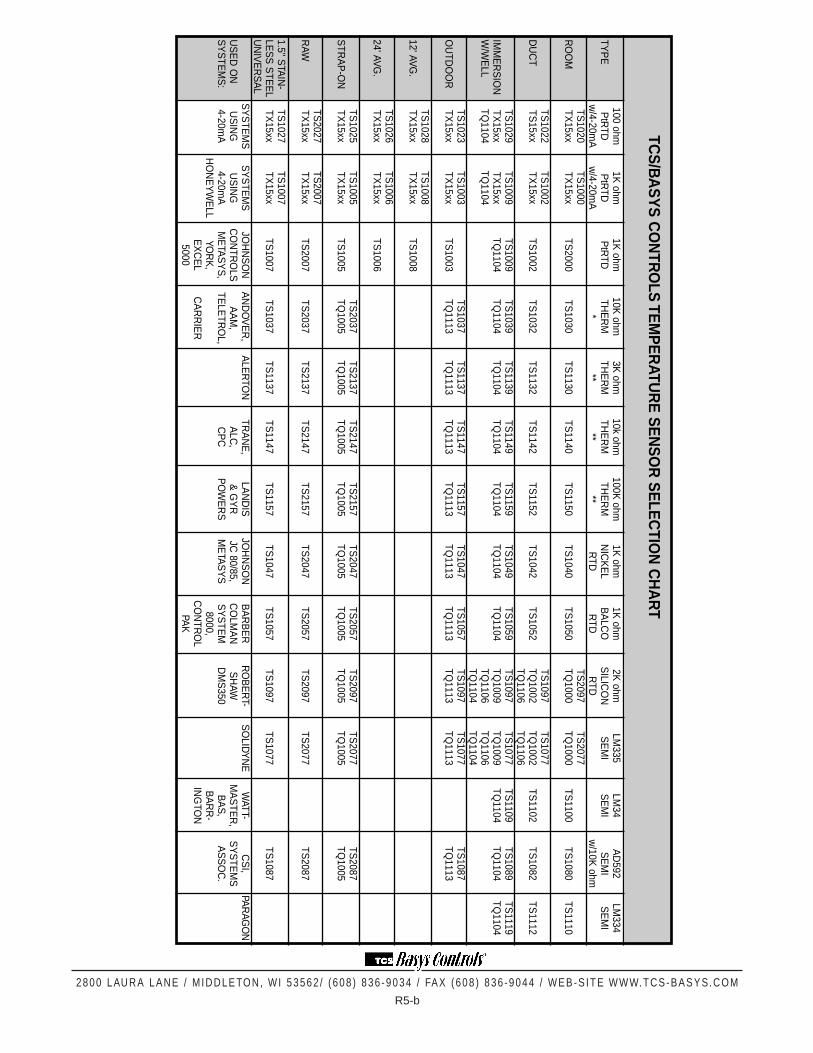
Temperature Sensors
2 8 0 0 L AU R A L A N E / M I D D L E TO N , W I 5 3 5 6 2 / ( 6 0 8 ) 8 3 6 - 9 0 3 4 / FA X ( 6 0 8 ) 8 3 6 - 9 0 4 4 / W E B - S I T E W W W. T C S - B A S Y S. C OM
R5-b
TCS
/BA
SY
S C
ON
TRO
LS TE
MP
ER
ATUR
E S
EN
SO
R S
ELE
CTIO
N C
HA
RT
100 ohm1K
ohm1K
ohm10K
ohm3K
ohm10k ohm
100K ohm
1K ohm
1K ohm
2K ohm
LM335
LM34
AD
592LM
334TY
PE
PtR
TDP
tRTD
PtR
TDTH
ER
MTH
ER
MTH
ER
MTH
ER
MN
ICK
EL
BA
LCO
SILIC
ON
SE
MI
SE
MI
SE
MI
SE
MI
w/4-20m
Aw
/4-20mA
***
****
RTD
RTD
RTD
w/10K
ohmTS
1020TS
1000TS
2097TS
2077R
OO
MTX
15xxTX
15xxTS
2000TS
1030TS
1130TS
1140TS
1150TS
1040TS
1050TQ
1000TQ
1000TS
1100TS
1080TS
1110
TS1022
TS1002
TS1097
TS1077
DU
CT
TS15xx
TX15xx
TS1002
TS1032
TS1132
TS1142
TS1152
TS1042
TS1052
TQ1002
TQ1002
TS1102
TS1082
TS1112
TQ1106
TQ1106
TS1029
TS1009
TS1009
TS1039
TS1139
TS1149
TS1159
TS1049
TS1059
TS1097
TS1077
TS1109
TS1089
TS1119
IMM
ER
SIO
NTX
15xxTX
15xxTQ
1104TQ
1104TQ
1104TQ
1104TQ
1104TQ
1104TQ
1104TQ
1009TQ
1009TQ
1104TQ
1104TQ
1104W
/WE
LLTQ
1104TQ
1104TQ
1106TQ
1106TQ
1104TQ
1104TS
1023TS
1003TS
1037TS
1137TS
1147TS
1157TS
1047TS
1057TS
1097TS
1077TS
1087O
UTD
OO
RTX
15xxTX
15xxTS
1003TQ
1113TQ
1113TQ
1113TQ
1113TQ
1113TQ
1113TQ
1113TQ
1113TQ
1113
TS1028
TS1008
12' AVG.
TX15xx
TX15xx
TS1008
TS1026
TS1006
24' AVG.
TX15xx
TX15xx
TS1006
TS1025
TS1005
TS2037
TS2137
TS2147
TS2157
TS2047
TS2057
TS2097
TS2077
TS2087
STR
AP
-ON
TX15xx
TX15xx
TS1005
TQ1005
TQ1005
TQ1005
TQ1005
TQ1005
TQ1005
TQ1005
TQ1005
TQ1005
TS2027
TS2007
RAW
TX15xx
TX15xx
TS2007
TS2037
TS2137
TS2147
TS2157
TS2047
TS2057
TS2097
TS2077
TS2087
1.5" STA
IN-
TS1027
TS1007
LES
S S
TEE
LTX
15xxTX
15xxTS
1007TS
1037TS
1137TS
1147TS
1157TS
1047TS
1057TS
1097TS
1077TS
1087U
NIV
ER
SA
LS
YS
TEM
SS
YS
TEM
SJO
HN
SO
NA
ND
OV
ER
,A
LER
TON
TRA
NE
,LA
ND
ISJO
HN
SO
NB
AR
BE
RR
OB
ER
T-S
OLIDY
NE
WATT-
CS
I,PA
RAG
ON
US
ED
ON
US
ING
US
ING
CO
NTR
OLS
AA
M,
ALC
,&
GY
RJC
80/85,C
OLM
AN
SH
AWM
AS
TER
,S
YS
TEM
SS
YS
TEM
S:
4-20mA
4-20mA
ME
TAS
YS
,TE
LETR
OL,
CP
CP
OW
ER
SM
ETA
SY
SS
YS
TEM
DM
S350
BA
S,
AS
SO
C.
HO
NE
YW
ELL
YOR
K,
8000,B
AR
R-
EX
CE
LC
AR
RIE
RC
ON
TRO
LIN
GTO
N5000
PAK
2 8 0 0 L AU R A L A N E / M I D D L E TO N , W I 5 3 5 6 2 / ( 6 0 8 ) 8 3 6 - 9 0 3 4 / FA X ( 6 0 8 ) 8 3 6 - 9 0 4 4 / W E B - S I T E W W W. T C S - B A S Y S. C OM
R5-c
WALL VS ROOM MOUNT TEMPERATURE SENSORSTCS wall mount sensors are available in platinum only. They are designed to be used with aTX1500 series temperature transmitter for application requiring a 4 to 20 mA input. Thesensor is mounted in the black strip at the bottom of the plate to eliminate self-heatingeffects from the transmitter, which mounts in the cube.
TCS/Basys Controls’ room mount sensors are available in platinum as well as other typesfor specific systems. They are for applications requiring a direct sensor signal. Note thatthe platinum version is shown. It is a three-wire sensor. If a two-wire connection is needed,use only the black and red wires.
Other room mount accessories include:
TQ1000 - Room housing with TCS logo TQ1020 - Room housing with no logoTQ1030 - Room housing with custom logo TQ1101 - Plastic conduit box adapter
(backplate for room mounts)
R
W
B
DUCT MOUNTSAll duct mount sensors come sealed in the probe andinclude the conduit box at the end. They are availablein 4” or 8” sizes. To make a special duct mount sensor,you must order the universal sensor, the probe, and thebox.
2 8 0 0 L AU R A L A N E / M I D D L E TO N , W I 5 3 5 6 2 / ( 6 0 8 ) 8 3 6 - 9 0 3 4 / FA X ( 6 0 8 ) 8 3 6 - 9 0 4 4 / W E B - S I T E W W W. T C S - B A S Y S. C OM
R5-d
AVERAGING DUCT MOUNTSAll averaging mount sensors are continuous averaging and includethe conduit box at the end. They are available in 12’or 24’sizes.Capillary mounting clips are included.
Accessories include:TQ1102 - Duct Mount Flange TQ1105 - NEMA 4 Conduit BoxQE01 - Capillary Mount Clips (100 pc)
Outdoor MountsAll outdoor mount sensors are sealed in silicone in a PVC tube that extendsfrom a weatherproof box. To make a special outdoor mount you need a quickresponse sensor, the weatherproof box, and the PVC tube. Accessories include:TQ1003 - PVC Tube TQ1113 - Weatherproof Box and PVC TubeTQ1103 - Weatherproof Box TQ1105 - NEMA 4 Conduit Box
MORE ON TEMPERATURE SENSORSUse the chart below to insure that you are using the correct sensor type.
The platinum sensors have a temperature coefficient of .00385 ohms/ohms/C or .00216 ohms/ohms/F. They are linear andhave an operating range of -50 to 375 F.
They output resistance. Since all wire has some resistance, you may need to use a three-wire sensor to eliminate the error,or offset the reading by a fixed value.
TWO-WIRE VS. THREE-WIRE SENSORSIf you measure from B to R in the top figure to the right, you will get a value that is equal to theresistance of the sensor plus the resistance of wire B plus the resistance of wire R. TCS transmittersallow for a three-wire connection. Look at the lower figure. The resistance of wire B is the same aswire R and wire W. The transmitters measure from B to R,and get the value as mentioned above,but they also measure from R to W, which is equal to the lead wire resistance, and subtract thisvalue.
OFFSETTING LEAD WIRE RESISTANCEIf a three-wire connection is not available, you may need to offset the resistance,which is constant. Use the chart to the right to determine the amount of lead wireresistance, and then calculate the percent error, depending on whether you areusing 100 or 1000 ohm sensors.
Note:Since lead wire resistance is fixed, it will be ten times less a factor for 1000ohm than 100 ohm!
2 8 0 0 L AU R A L A N E / M I D D L E TO N , W I 5 3 5 6 2 / ( 6 0 8 ) 8 3 6 - 9 0 3 4 / FA X ( 6 0 8 ) 8 3 6 - 9 0 4 4 / W E B - S I T E W W W. T C S - B A S Y S. C OM
R6-a
GENERALTemperature transmitters are designed to input 100 or 1000 ohm platinum sensors. They take theresistance signal and convert it to a current signal. The output span is 4 to 20 mA. They are poweredby the loop.
SetupA jumper must be placed on either #1 or #2,depending whether the sensor is 100 or 1000 ohm. If thejumper is on 1000,and you are using a 100 ohm,you will always have a signal of at most 4 mA.Likewise, if the jumper is on 100,and if you are using a 1000 ohm sensor, you will always have asignal of at least 20 mA.
A jumper is factory installed according to the span resolution on either #3 or #4. This jumper shouldnot be moved unless following the calibration procedure on the next page.
A jumper should be placed on J2 in the bottom right corner if you are only using a two-wire sensor,and jumps the white terminal to the red.
Wiring to Sensor
If you are using a two-wire sensor, the sensor should be wired into the black terminal and one ofother terminals.
If you are using a three-wire sensor, it may have a red, black, and white lead. They connect directlyto the transmitter as indicated. If your sensor instead has two like color wires,and one different color,connect the like to the red and white terminals and the different to the black.
Wiring to Contr ollerTCS/Basys controllers have a +P terminal that feeds power for the transmitter. The figure aboveshows how to wire into the S-series controllers. Shown below are diagrams to wire them into othercontrollers.
R
Temperature Transmitters
-+
-+
Wiring to another loop-powering controller:
TransmitterController
Wiring using a separate power supply:
-+
-+
TransmitterPower
-
Controller
+
2 8 0 0 L AU R A L A N E / M I D D L E TO N , W I 5 3 5 6 2 / ( 6 0 8 ) 8 3 6 - 9 0 3 4 / FA X ( 6 0 8 ) 8 3 6 - 9 0 4 4 / W E B - S I T E W W W. T C S - B A S Y S. C OM
R6-b
SPANSTemperature transmitters output a linear 4 to 20 mA signal which is spanned to a factory calibratedspan. Shown are the outputs of the transmitters vs. temperature.
4 8 12 16 20 mA Output
40
90
65
77.5
52.5
°F
TX1500
4 8 12 16 20 mA Output
-40
160
60
110
10
°F
TX1501
4 8 12 16 20 mA Output
0
100
50
75
25
°F
TX1502
4 8 12 16 20 mA Output
50
150
100
125
75
°F
TX1503
4 8 12 16 20 mA Output
40
240
140
190
90
°F
TX1504
4 8 12 16 20 mA Output
0
150
75
127.5
37.5
°F
TX1505
4 8 12 16 20 mA Output
20
120
70
95
45
°F
TX1506
4 8 12 16 20 mA Output
-30
130
50
90
10
°F
TX1507
4 8 12 16 20 mA Output
50
85
67.5
76.25
58.75
°F
TX1508 (or TX1130)
4 8 12 16 20 mA Output
40
140
90
115
65
°F
TX1509
4 8 12 16 20 mA Output
100
250
175
212.5
137.5
°F
TX1510
2 8 0 0 L AU R A L A N E / M I D D L E TO N , W I 5 3 5 6 2 / ( 6 0 8 ) 8 3 6 - 9 0 3 4 / FA X ( 6 0 8 ) 8 3 6 - 9 0 4 4 / W E B - S I T E W W W. T C S - B A S Y S. C OM
R6-c
TEMPERATURE TRANSMITTER RECALIBRA TION PROCEDURE
Required items1. An 8-35 VDC regulated power
supply (CP1030/QE31)2. An accurate (DMM) current
meter3. A resistance simulator/ decade
box (QE50 or QE51)
Hookup (See dia gram.)1. + of power to + of transmitter2. - of transmitter to + of current
meter3. - of current meter to GND of
power4. Resistance simulator to sensor
input5. Put a jumper on #1 or #2 (100 or
1000 ohm simulation)6. Put a jumper on #3 or #4,depending or desired range span. (Span < 150°F or span > 150°F)7. Put a jumper on “J2”.
Calibration1. Set simulator to ohms corresponding to the LOW end of the desired span. Using the ZERO pot on
the transmitter, adjust until the current meter reads 4 mA.2. Set simulator to ohms corresponding to the HIGH end of the desired span. Using the GAIN pot on
the transmitter, adjust until the current meter reads 20 mA.3. Redo the above two steps until you have readings within your desired tolerance. 4. Check the midpoint of the range to verify that the current meter reads 12 mA.
Recalibtration Wiring
2 8 0 0 L AU R A L A N E / M I D D L E TO N , W I 5 3 5 6 2 / ( 6 0 8 ) 8 3 6 - 9 0 3 4 / FA X ( 6 0 8 ) 8 3 6 - 9 0 4 4 / W E B - S I T E W W W. T C S - B A S Y S. C OM
R7-a
Humidity transmitters output a 4 to 20 mA signal linear to the relative humidity, scaled 0 to 100 %.The sensor is a bulk polymer resistive sensor which is very durable and can be cleansed with distilledwater.
Humidity Transmitter Mounting Configurations.
There are four different accuracies; 1,2, 3, and 5 %. The 1 and 2 % come with the certif icate shownbelow. The 3 % is the most common.
R
Humidity Transmitters
Wall Mount Duct Mount Outdoor Mount
2 8 0 0 L AU R A L A N E / M I D D L E TO N , W I 5 3 5 6 2 / ( 6 0 8 ) 8 3 6 - 9 0 3 4 / FA X ( 6 0 8 ) 8 3 6 - 9 0 4 4 / W E B - S I T E W W W. T C S - B A S Y S. C OM
R8-a
The TZ1002 is a relative humidity transmitter (4 to 20 mA) with a 100 ohmplatinum sensor mounted in a double gang box for duct or outdoor mount. If a4 to 20 mA signal is desired for temperature, you must order a TX15xx seriestransmitter with it. The transmitter may be mounted inside the box or external-ly.
R
TZ1002 Temp and Humidity Combo
2 8 0 0 L AU R A L A N E / M I D D L E TO N , W I 5 3 5 6 2 / ( 6 0 8 ) 8 3 6 - 9 0 3 4 / FA X ( 6 0 8 ) 8 3 6 - 9 0 4 4 / W E B - S I T E W W W. T C S - B A S Y S. C OM
R9-a
MEASURING AIR PRESSURE - TD/L SERIES
R
Pressure Transducers
TD/TL SERIES
DIFFERENTIALPRESSURETRANSDUCER
R
ZERO ADJUST
SPAN ADJUST
SPAN SELECT
HIGH PRESSURE
LOW PRESSURE
a
b
c
abc
SPAN ADJUST
a
b
c
SPAN SELECTabc
TL1160 TD1190 TD1191abc
span in "wcd
-.25 to .25
-.25 to .75
-.25 to 1.75
0 to 1 0 to 5
0 to 2 0 to 6
0 to 3 0 to 10
+P
AI
Wiring to a TCS Basys controller which loop powers the transducer.
Other Loop-powered controller
PRESSURE CONNECTIONS: (Use 1/4" pneumatic tubing)Duct Static Pressure: Connect the high port to the duct facing away from flow. Connect the low port to the space.Building Static Pressure: Connect the high port to the space. Connect the low port to the outside air.
Velocity Pressure: Connect the high port to the air flow measuring station port or pitot tube port that faces the flow. Connect the low port to the air flow measuring station port or pitot tube port that faces away from the flow.
ZERO ADJUST
With no pressure connections (zero pressure), the TD1190 and
TD1191 should output 4 mA. The TL1160 should output 12
mA if on span a, 8 mA if on span b, or 6 mA if on span c. You may use this screw to fine tune this
value.
DO NOT ADJUST! unless you have accurate pressure
calibration instruments. Doing so may violate
your warranty.
Using an external power supply
Power Requirements:
12 VDC + R*x(0.020) to 35 VDC
*Input impedance of the controller
Pow
er Supply
Controller
2 8 0 0 L AU R A L A N E / M I D D L E TO N , W I 5 3 5 6 2 / ( 6 0 8 ) 8 3 6 - 9 0 3 4 / FA X ( 6 0 8 ) 8 3 6 - 9 0 4 4 / W E B - S I T E W W W. T C S - B A S Y S. C OM
R10-a
The I-series consists of interface devices and display modules. They may be used as stand-alone ormay share information over the C-series bus. (The exception is the IP1013,which is stand-aloneonly.)
I-SERIES COMPONENTS
IA1102 - Analog Rescaler
The IA1102 accepts any range within 0 to 20 VDC or 0 to 40 mA DC and outputsany range within 0 to 20 VDC or 0 to 40 mA DC. It is commonly used to convertthe TCS 4 to 20 mA signal to a 0 to 10 VDC or 0 to 5 VDC signal. Two can alsobe plugged together to create two signals from one. Setup is required, using avoltage or current source and a digital multimeter (DMM).
IR1203 - Analog to Resistive Transducer
The IR1203 accepts a 4 to 20 mA signal and outputs either a 0 to 135 ohm,0 to500 ohm,or 0 to 1000 ohm signal,depending upon the which of three boards(included) is placed inside. It is commonly used to interface the 4 to 20 mA sig-nal to a 0 to 135 ohm motor.
IP1013 - Pneumatic Transducer
The IP1013 accepts a 4 to 20 mA signal and outputs a 3 to 15 PSI signal. It iscommonly used to interface the 4 to 20 mA signal to a pneumatic damper orvalve. It can be set for reverse or direct action.
R
Interface Devices - I Series
2.4V VOUT GAIN OFFSET
2 8 0 0 L AU R A L A N E / M I D D L E TO N , W I 5 3 5 6 2 / ( 6 0 8 ) 8 3 6 - 9 0 3 4 / FA X ( 6 0 8 ) 8 3 6 - 9 0 4 4 / W E B - S I T E W W W. T C S - B A S Y S. C OM
R10-b
ID1000 Series - Digital indicator s
The ID1000 Series are LED indicators. They accept two 4 to 20 mA,2 to 10 VDC,or 1 to 5 VDC inputs,which must be scaled to the same range. The main inputwill show continuously, and the second input will show when the button on thefront is pressed. They may be used as stand-alone or may be plugged on the frontof a CC1140 or CX1140 to display process variable and setpoint. They come in 10spans and are easily recalibrated with a voltage or current source. Unless they areplugged on the front of a C-series module, they require 24 VAC or 24 VDC exter-nal power.
The ID1100 Series are LCD indicators. They only accept 4 to 20 mA inputs andare powered from the loop. They will show the main input continuously, and thesecond input when the button is pressed. They can be recalibrated in the same way
that the ID1000 Series are, with a 4 to 20 mA source.
2 8 0 0 L AU R A L A N E / M I D D L E TO N , W I 5 3 5 6 2 / ( 6 0 8 ) 8 3 6 - 9 0 3 4 / FA X ( 6 0 8 ) 8 3 6 - 9 0 4 4 / W E B - S I T E W W W. T C S - B A S Y S. C OM
R11-a
The C-series consists of analog control modules and their accessories,including high and low selectmodules,limit modules,and power supplies. These modules may be used as stand-alone devices ormay share information with other C and I devices on the Basys busline.
C - SERIES COMPONENTS
CC1140 - PID Contr oller
The CC1140 accepts a 4 to 20 mA signal,as well as a setpoint from the bus orthe front dial,and outputs a 4 to 20 mA control signal. They are commonlyused to control variable speed drives.
CX Series - Two Position Contr oller s
The CX1140 accepts a 4 to 20 mA signal,as well as a setpointfrom the bus or the front dial,and provides control of an SPDTrelay. Two additional stages may be added to the CX1140 orCC1140 by plugging on the CX2142. Although the sameprocess variable and setpoint would be used, offset and differ-ential values are set for each stage using the dials on the con-troller.
CI1140 - Reset Module
The CI1140 is designed to be used with the CX1140 or the CC1140,is applica-tions where the setpoint is reset from a second variable, such as hot water offoutdoor air. It accepts two inputs and plugs together with the other module. Theschedule must be such that when the second variable decreases,the setpointincreases. As a stand-alone device, the CI can provide an average or weightedaverage of two 4-20mA input signals.
R
Analog Control Modules - C Series
2 8 0 0 L AU R A L A N E / M I D D L E TO N , W I 5 3 5 6 2 / ( 6 0 8 ) 8 3 6 - 9 0 3 4 / FA X ( 6 0 8 ) 8 3 6 - 9 0 4 4 / W E B - S I T E W W W. T C S - B A S Y S. C OM
R11-b
CS Series - High/Lo w Select Modules
The CS1402 accepts three 4 to 20 mA signals and outputs thelowest of the three.
The CS1403 accepts three 4 to 20 mA signals and outputs thehighest of the three.
The CS1404 accepts two 4 to 20 mA signals and outputs thehighest and lowest of the two.
CQ1101 - Minim um Position Module
The CQ1101 accepts one 4 to 20 mA signal and outputs the same signal clippedoff above or below the specified level, determined by the setpoint dial. It is com-monly used to minimum position outdoor air dampers.
A second function of the CQ1101 is to output the setpoint on the dial,making ituseful for panel mounted setpoint adjustment.
CP Series - Power Supplies
The CP1028 is designed to provide power for the Basys bus line, with the bene-fit of no external wiring. It accepts 115 or 230 VAC and outputs 24 VDC. It hasa 2 A fuse for system protection.
The CP1030 is designed to provide power for any of the T series transducerswhen they are used with systems that do not provide loop power. A jumperselection determines half-wave or full-wave rectification. (TCS uses all half-wave rectification.) It accepts 24 VAC and outputs 3 to 27 VDC, which is setwith an adjustable pot.
A QE31 transformer is also available which accepts 120,208,or 240 VAC andoutputs 24 VAC.
2 8 0 0 L AU R A L A N E / M I D D L E TO N , W I 5 3 5 6 2 / ( 6 0 8 ) 8 3 6 - 9 0 3 4 / FA X ( 6 0 8 ) 8 3 6 - 9 0 4 4 / W E B - S I T E W W W. T C S - B A S Y S. C OM
R12-a
R
Army CorpsSD1000 Single-loop Contr oller
The SD1000 single-loop controller was designed to meet theArmy Corps of Engineers’ specification. It is installed inalmost every army base and facility across the country, aswell as many industrial facilities. It mounts flush in a paneland is powered by 110 or 220 VAC, which makes it differentfrom all other S-series products.
The SD1000 accepts one primary 4 to 20 mA input as theprocess variable, and one secondary 4 to 20 mA input for set-point or reset. It also accepts two digital inputs which shiftthe setpoint. It outputs one primary 4 to 20 mA output formain control and one secondary 4 to 20 mA output which caneither retransmit the setpoint,retransmit the primary input,orbe used as a cooling output when the primary output is usedfor heating in special cases. It also has two independent digi-tal SPDT relay outputs.
The Army Corps of Engineers has a complete technical manual (TM 5-815-3) describing the applica-tion of single-loop controllers. Generally, the Army Corps Single Loop Controller specifications fol-low the same specific guidelines.
TCS/BASYS CONTROLS PARTS THAT MEET CEGS 15950:
TCXXXX
ECXXXX
PCXXXX
RHCXXXX
FCXXXX
TCXXXX
SD1000 is used for any of these controllers.
LDXXXX
= IA1102 MPSXXXX
= CQ1101
TYXXXX
= CS1404
IPXXXX
= IP1013
DPTXXXX
= TL1160, TD1190, or TD1191
DPIXXXX
= ID10xxRHY
XXXXOR
RHTXXXX
= TH1011, TH1021, TH1211, or TH1111RHTXXXX
= TH1010, TH1020, TH1210, or TH1110
TTXXXX
=TSxxxx with TX15xx TTXXXX
OR
2 8 0 0 L AU R A L A N E / M I D D L E TO N , W I 5 3 5 6 2 / ( 6 0 8 ) 8 3 6 - 9 0 3 4 / FA X ( 6 0 8 ) 8 3 6 - 9 0 4 4 / W E B - S I T E W W W. T C S - B A S Y S. C OM
R12-b
GENERAL ARMY CORPS SPECSTransmitters are externally powered as opposed to loop powered.
Two controllers are generally used for temperature control when both heating and cooling are pre-sent.
Economizer control is achieved with two controllers; one that outputs a modulating signal based onmixed air, and one that accepts outdoor and return air signals and makes a contact that allows themixed air dampers to modulate when conditions are favorable. A signal from a minimum positionmodule also goes to the high signal selector, as does the signal from the mixed air controller. Theoutput from the high signal selector goes to the damper actuator.
Boiler reset control is achieved with two controllers. One inputs the outdoor air temperature and thesecond inputs the boiler temperature. This is covered thoroughly in the back of the SD1000 installa-tion manual.
Outdoor and mixed air spans are generally -30 to 130 F (TX1507). Hot water temperature spans aregenerally 40 to 240 F (TX1504).
TROUBLESHOOTING HINTS
Problem: LLLL is sho wn on the screen.Meaning:The input into AI1 is below 4 mA.
Verify the input into AI1 is at least 4 mA by by measuring the volts from AI1 (#16) to ground (#12).If it is not at least .4 VDC, the problem is in your transmitter or sensor setup or wiring.
Problem: HHHH is sho wn on the screen.Meaning:The input into AI1 is above 20 mA.
Verify the input into AI1 is below 20 mA by measuring the volts from AI1(#16) to ground (#12). If itis more than 2 VDC, the problem is in your transmitter or sensor setup or wiring.
Problem: 8888 (or other od d messa ge) is sho wn on the screen.Meaning:The controller may have been subjected to a power surge.
Press the hidden reset button,which is located directly above the "auto-tune" key on the face.
Problem: Contr oller does not store c hang ed values.Meaning:Enter was not pressed after the change was made.
Go back to the step with the desired change, make the change and press enter. Scroll back through toverify that the change was made.
Problem: Propor tional band is half of what is entered.Meaning:The controller is in 1H2C mode. (Step #12)
If you are only using one output,choose either of the other options. If you are using both outputs,notice that the proportional band pertains to both outputs,and should be doubled.