31
Bitter, Rick et al "Application Structure" LabVIEW Advanced Programming Techinques Boca Raton: CRC Press LLC,2001

Bitter, Rick et al "Application Structure"LabVIEW Advanced Programming TechinquesBoca Raton: CRC Press LLC,2001

4 Application Structure
This chapter provides insight into developing well-structured applications, and willbe particularly helpful for those applications that are relatively large. Several topicswill be discussed that are important to the success of a software project. First, thevarious issues that must be considered before development can begin will be lookedat. Then, the role of structure, or framework, of applications and its importance willbe explained. The sections that follow will elaborate on software models, projectadministration, and the significance of documentation.
The three-tiered approach will then be presented as a framework for well-structured applications, stressing the importance of strict partitioning of levels. Thistopic will include the main, test, and driver levels of an application. The chapterwill conclude with a summary example.
4.1 PLANNING
Complex architectures are not needed when the application being developed issimple. It is relatively easy to throw together a program in LabVIEW for performingspecific functions on a small scale. But when the application becomes large in size,several design considerations should be taken into account before coding can begin.The following issues, among others, need to be considered: flexibility, extensibility,maintainability, code reuse, and readability.
Flexibility and extensibility impact the ability of an application to adapt to futureneeds. The ability to add functionality after the application has been released shouldbe designed into the code. It is almost inevitable that requirements will change afterthe program is released. The architecture of large applications needs to be designedwith the ability to make additions. For example, the end user may demand additionalfunctionality to meet new requirements. If the application was not designed withthe capacity to evolve, incremental enhancements can prove to be very difficult. Theneeds of the user evolve over time, and a well-designed application can easily adapt.
Maintainability of code is necessary for applications so that needed modificationscan be made easily. The concept of allowing for change in functionality holds truefor the ability to maintain and modify code easily. For example, if a power supplythat is being used in the current test setup will not be used in another test rack, youmay need to change to a different model. How easily your code can be modified toreflect this change in the test setup is material. The amount of work involved in thealteration depends on how the code is structured.
Code reuse is required for cycle-time reduction on future projects. This attributeis often overlooked because programmers focus on accomplishing the goal of the
©2001 CRC Press LLC

current project. The time it takes to complete future projects can be reduced if evensmall pieces of the code can be reused. When software is written in a way that itcannot be reused, efforts are duplicated unnecessarily. Both time and money can besaved when a project is developed with reuse as a design goal.
The ability of the software to provide abstraction is also significant because itimproves code readability. Not everyone interacting with the program needs thesame level of abstraction. Someone who will use the application, but knows nothingabout programming, does not need or wish to see the low level data manipulationof the program. Operators want an easy user interface that will allow them to usethe application for their specific purpose. On the other hand, the person in chargeof writing and maintaining the application needs to see all levels of the program.Abstraction allows the programmer to conceal subsections of the application fromthose who would not benefit from seeing it. Drivers abstract the I/O so it is easierto understand the test level. The test level abstracts the logic so the main level iseasier to read.
The concepts presented in this chapter are a good starting point for beginninga project. “Plans are nothing; planning is everything,” is a quote by Dwight D.Eisenhower that is applicable to software design. Without adequate planning, largeapplications are not as likely to be successful. Planning provides a roadmap fordevelopment and helps minimize the occurrence of unexpected events. You can planwith contingencies depending on the results of the design stages.
Inadequate planning is more likely to result in problems. When designing anapplication, detailed knowledge of the system — instruments, software requirements,feature sets, etc. — plays a significant role in building a successful application.
4.2 PURPOSE OF STRUCTURE
The topics discussed on application structure may be applied to programming lan-guages other than LabVIEW. Architecture and process are two elements that areimportant in all languages. The structure of the program or framework that is usedis important for future additions, modifications, and maintenance. If the correctprocess is taken in designing the software system, the application can change as theneeds of the user change. These things should be taken into account in the earlystages of the development process. Systematically approaching the development ofan application means deciding on a process.
The importance of heuristics as discussed by Rechtin and Maier should also beconsidered. Several rules of thumb that guide the development process will bepointed out as the three-tiered approach is described. These are suggestions andideas that have been learned through experience.
As is the case in any programming language, the programmer must take thetime to understand the nature of the task at hand and what the purpose of the projectis. By this, we mean the project requirements should be well defined. There shouldbe a clear goal or end result for the project. Defining the requirements is one of thefirst stages in the development of any application. Some people believe that a bigportion of the project is completed once the detailed requirements are defined anddocumented. An example is writing an application to monitor process control. The
©2001 CRC Press LLC
user requirements might include the number of items to monitor as well as thefrequency of the sampling. You must decide what instruments will be used, the typeof communications (serial, GPIB, etc.), what specific measurements are needed,where the data will be sent, and who the end users of this application are. These areconsidered derived requirements. Together, these are some of the more general itemsthat would be included in the enumerated list of requirements.
The requirements are key deliverables for a software project. One of the mostcommon reasons software projects run over budget and beyond due dates involvesnot having the requirements defined. There is a tendency to add new features intothe application late in the development cycle. If the requirements keep changing, itwill be difficult to adhere to limited schedules and budgets. You must lock in therequirements to prevent “feature creep.”
When the requirements are very loosely defined or not defined at all, the endresult has many possibilities. Failing to document the needs of the customer canprove to be very costly. A lot of time and money will be wasted in making changesto fit customer needs. It can be avoided if time is spent earlier in the process. Ifrequirements are not in writing, contract payments may not be made.
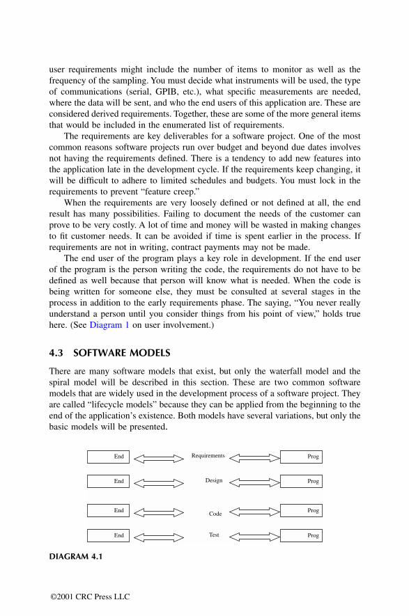
The end user of the program plays a key role in development. If the end userof the program is the person writing the code, the requirements do not have to bedefined as well because that person will know what is needed. When the code isbeing written for someone else, they must be consulted at several stages in theprocess in addition to the early requirements phase. The saying, “You never reallyunderstand a person until you consider things from his point of view,” holds truehere. (See Diagram 1 on user involvement.)
4.3 SOFTWARE MODELS
There are many software models that exist, but only the waterfall model and thespiral model will be described in this section. These are two common softwaremodels that are widely used in the development process of a software project. Theyare called “lifecycle models” because they can be applied from the beginning to theend of the application’s existence. Both models have several variations, but only thebasic models will be presented.
DIAGRAM 4.1
End Requirements
Design
Code
Test
End
End
End
Prog
Prog
Prog
Prog
©2001 CRC Press LLC
4.3.1 THE WATERFALL MODEL
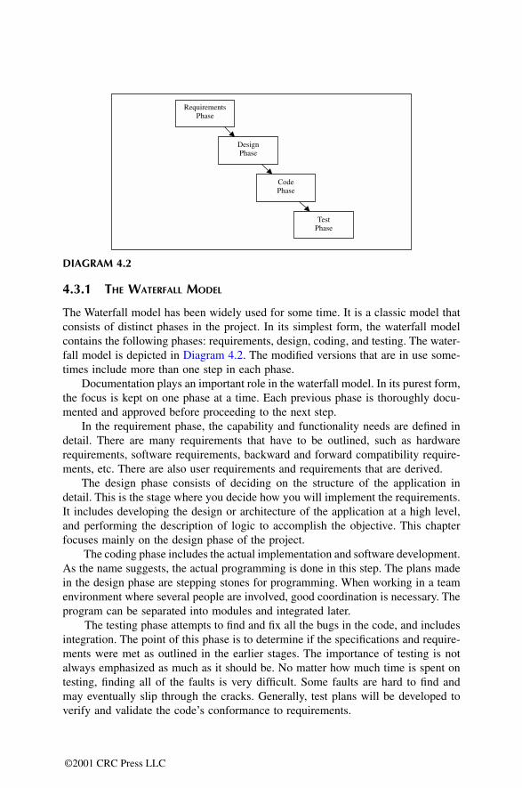
The Waterfall model has been widely used for some time. It is a classic model thatconsists of distinct phases in the project. In its simplest form, the waterfall modelcontains the following phases: requirements, design, coding, and testing. The water-fall model is depicted in Diagram 4.2. The modified versions that are in use some-times include more than one step in each phase.
Documentation plays an important role in the waterfall model. In its purest form,the focus is kept on one phase at a time. Each previous phase is thoroughly docu-mented and approved before proceeding to the next step.
In the requirement phase, the capability and functionality needs are defined indetail. There are many requirements that have to be outlined, such as hardwarerequirements, software requirements, backward and forward compatibility require-ments, etc. There are also user requirements and requirements that are derived.
The design phase consists of deciding on the structure of the application indetail. This is the stage where you decide how you will implement the requirements.It includes developing the design or architecture of the application at a high level,and performing the description of logic to accomplish the objective. This chapterfocuses mainly on the design phase of the project.
The coding phase includes the actual implementation and software development.As the name suggests, the actual programming is done in this step. The plans madein the design phase are stepping stones for programming. When working in a teamenvironment where several people are involved, good coordination is necessary. Theprogram can be separated into modules and integrated later.
The testing phase attempts to find and fix all the bugs in the code, and includesintegration. The point of this phase is to determine if the specifications and require-ments were met as outlined in the earlier stages. The importance of testing is notalways emphasized as much as it should be. No matter how much time is spent ontesting, finding all of the faults is very difficult. Some faults are hard to find andmay eventually slip through the cracks. Generally, test plans will be developed toverify and validate the code’s conformance to requirements.
DIAGRAM 4.2
Requirements�Phase
Design�Phase
Code�Phase
Test�Phase
©2001 CRC Press LLC
The waterfall model heavily stresses the importance of the requirements phaseto eliminate or reduce problems early. The requirements must be explicitly outlinedin this model before work can begin on the next phase. Keep in mind that definingdetailed requirements will not always translate into a good application structure.However, it does bring to attention the important phases that are involved in appli-cation development. This model is aimed at getting the project completed in onepass. Returning to a previous phase to make changes using this model can becomecostly because one phase is to be completed before the next phase begins.
4.3.2 THE SPIRAL MODEL
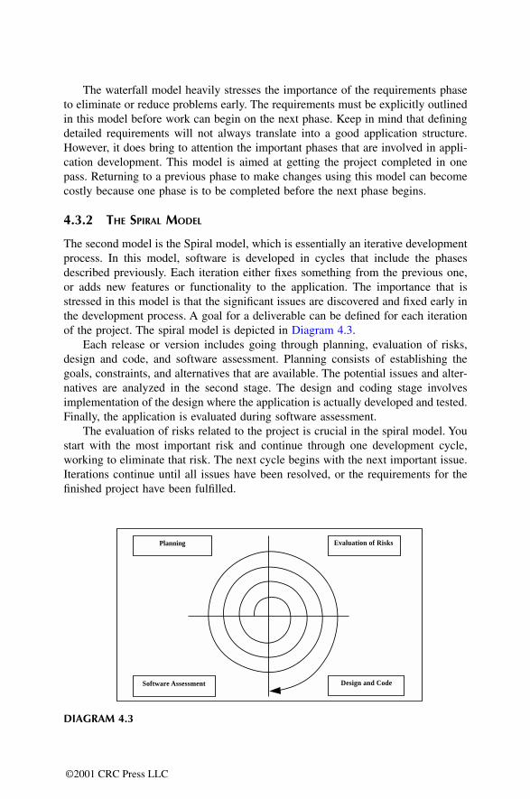
The second model is the Spiral model, which is essentially an iterative developmentprocess. In this model, software is developed in cycles that include the phasesdescribed previously. Each iteration either fixes something from the previous one,or adds new features or functionality to the application. The importance that isstressed in this model is that the significant issues are discovered and fixed early inthe development process. A goal for a deliverable can be defined for each iterationof the project. The spiral model is depicted in Diagram 4.3.
Each release or version includes going through planning, evaluation of risks,design and code, and software assessment. Planning consists of establishing thegoals, constraints, and alternatives that are available. The potential issues and alter-natives are analyzed in the second stage. The design and coding stage involvesimplementation of the design where the application is actually developed and tested.Finally, the application is evaluated during software assessment.
The evaluation of risks related to the project is crucial in the spiral model. Youstart with the most important risk and continue through one development cycle,working to eliminate that risk. The next cycle begins with the next important issue.Iterations continue until all issues have been resolved, or the requirements for thefinished project have been fulfilled.
DIAGRAM 4.3
Planning
Software Assessment
Evaluation of Risks
Design and Code
©2001 CRC Press LLC

The spiral model is based on the concept of incremental development duringeach iteration. The highest priority items, consisting of risks or features, areaddressed and implemented first. Then, the project is reevaluated, and the highestpriority item is defined and implemented in the next iteration. The first release ofan application can consist of the first loop, and following versions add new featuresas more iterations are made.
The spiral model is best when the requirements are not fully defined and devel-opment work must begin quickly. Iterative models create an early version of theapplication for demonstration purposes and further refinement. If the risks cannotbe identified easily, this model may not work very well.
4.3.3 BLOCK DIAGRAMS
Using a particular model will not guarantee success, but nevertheless provides anorderly roadmap for the development process. Following one model strictly may notbe the best course. There should be sufficient flexibility to take the specific circum-stances into consideration. Sometimes it is enough to keep in mind that there aredifferent phases in the models and adapt them to the current project.
In either model, block diagrams are useful tools that can assist in the design ofthe application. When using a top-down design approach, the block diagram, orhierarchy, helps get the structure defined. It also assists in separating tasks for theproject and developing timelines for completion. In this way the developer can getthe big picture of how the application is laid out and how to progress in the codingphase. The top-down design is more suitable for large applications where work canbegin on the user interface and main level first. Work can then continue down to thedriver level. In the bottom-up design, the drivers that will be needed for the programare worked on first. At most, a small team should be responsible for the architectureof the project. This facilitates management and prevents pulling the project in variousdirections.
4.3.4 DESCRIPTION OF LOGIC
A large application must be designed before the coding phase can begin. The require-ments determine what the application must do. The design or architecture determineshow the application will actually do it. The design phase of a project includes devel-oping the architecture as well as description of logic for the implementation.
The architecture consists of the framework that will be used for the application,taking code reuse, readability, and flexibility into consideration. This can be doneby creating flow diagrams or designing the VI hierarchy for LabVIEW applications.The software architecting is followed by definition of the logic that will be used toperform the actual coding.
In the description of logic, the designer must describe the logic of each VI inthe hierarchy. The description of logic should capture the intention of the VIs andprovide documentation at the same time. This will prevent rework and reduce thetime it takes to develop the application. A description should include both thepurposes of the VI and how it will accomplish its objective. The purpose should
©2001 CRC Press LLC
simply be one sentence describing what the VI will do. When several sentences areneeded to describe the action of the VI, the code can possibly be broken down intosubVIs. This will increase readability and maintainability of the code. For example,“This VI will configure the signal generator for test A,” illustrates the intent of theVI. When describing how the objective will be accomplished, include what VIs willbe called and why they will be called.
The coding phase will utilize the description of logic for development of theapplication. This is followed by the test phase where the code and the descriptionof logic are validated. A test plan must be used to verify the description of logic.This is done by developing test cases designed to test different portions of thedescription of logic.
4.4 PROJECT ADMINISTRATION
A single programmer project can have its process managed by the programmer.Management of the development process may not be a big problem in this situation.However, projects are often worked on by teams composed of several members.When more than one person works on an assignment, the need for a team leaderarises. Someone has to drive the project and control the direction of its progress.The whole development process needs management. Decisions must be made onhow and whether to continue to the next phase.
One team member must assume the role of project manager. Without someoneto focus on the overall goal of the project, the goals of the members can becomedivergent. When a team works on all phases of the application, the team leaderbecomes the lead designer and the one who ensures that the process is moving inthe right direction. When separate teams are working on each phase of the applica-tion, a project manager is needed to work with all the teams involved. The projectmanager has to make sure that the designers, programmers, and testers work togetherand are synchronized. Clear roles have to be assigned to the individual members.
Projects have constraints and risks regarding cost, schedule, and performance.The project manager has to practice techniques to control the risks and constraints.Scheduling is a crucial aspect of the administration of a project. Some stages haveto be finished before work can begin on the next stage. Goals and milestones haveto be achieved in a timely manner. The project manager works with all who areinvolved and is made aware of problems as they arise. Resources can be shiftedwhere necessary to assist in problem resolution and to meet schedules. Deadlinesare strategic issues that must be dealt with in the appropriate manner. In some casesit might be preferable to be over budget and on time than to be late but in budgetconstraints. In other cases it is better to be late with a high-quality and high-reliabilityproduct.
The administrator should have a good understanding of the complete system. Ifthe project manager is involved in the early idea conception and requirements stages,then this person will have a better grasp of the purpose of the application. Betterdecisions can be made on the priorities of the task at hand and how to resolveconflicts. Information must be acquired, evaluated, interpreted, and communicatedto the group members as necessary.
©2001 CRC Press LLC
Software projects are more difficult to manage than other types of projects forseveral reasons. It is difficult to make estimates on the project size, schedules, scope,and resources needed. Software projects can fail due to inaccurate estimates on anyof these aspects. Planning plays a key role in project management.
4.5 DOCUMENTATION
When a software application is being developed, the proper documentation is oftenoverlooked. Many times, the documentation process will begin only after all thecoding has been completed. This results in insufficient reports on the proceduresfollowed and the actual code written. When you return to write documentation aftercompleting the project, you tend to leave out design decisions that are important tothe development. Then, the record keeping becomes more of a chore and fails toserve its intended purpose.
Good documentation will allow someone not involved in the development toquickly identify and understand the components of the project. It also provides agood design history for reference purposes on future software projects. Accountsshould be kept at all of the phases in the development cycle. The requirementsdocuments are significant because they will guide the rest of the phases. The designphase documentation serves as a reference for the coding phase.
Documentation during the coding phase, or Description of Logic, is critical.Major points help understand what the code is supposed to do. Comments that areincluded with the code help identify the different segments and the purpose of eachsegment. They aid in the maintenance, modification, and testing of the code. Updat-ing the code becomes easier for someone who was not involved in the developmentprocess. The original programmers may be reallocated, transferred, or may evenleave the company. Then, problems can arise for those who use the program andhave to make modifications.
4.5.1 LABVIEW DOCUMENTATION
LabVIEW has some built-in functions to help in the documentation of code. As withother programming languages, comments can be included in the appropriate placeswith the code. This allows anyone to look at the diagram and get a better under-standing of the code. When modifications have to be made, the comments can helpidentify the different areas in addition to their functionality.
LabVIEW allows the programmer to enter descriptions for front panel controlsand indicators. When Show Help has been activated from the Help menu, simplyplace the cursor over the control or indicator to display its description. To enter thedescription, pop up on the control and select Data Operations from the menu. Thenselect Description and a window appears that will allow you to type in the relevantinformation. These descriptions will assist anyone who is using the application toidentify the purpose of the front panel controls and indicators
Descriptions can also be added for each VI that is developed, using the Show VIInfo selection under the Windows menu. You can include relevant details of the VI,
©2001 CRC Press LLC
inputs, and the outputs. When the Show Help is activated from the Help menu, thisVI information will appear in the Help window if you place the cursor over the icon.Help files can also be created and linked to LabVIEW in an on-line form. They haveto be created in Windows format and compiled before they can be used in LabVIEW.
4.5.2 PRINTING LABVIEW DOCUMENTATION
You can also select Print Documentation from the File menu and LabVIEW willallow you to customize the way you want to print the documentation. The VI Infothat was entered will be included. A feature that has been added with LabVIEW 5.0is the ability to print documentation to an HTML file. This file can then be publishedeasily on the Web. Options for saving files in RTF format or as plain text files arealso available. The user can select this from the Destination drop-down menu in thewindow after Print Documentation has been selected. The pictures of the codediagram and front panels can be saved as JPEG or GIF formats for other purposes.
4.5.3 VI HISTORY
Another way to document LabVIEW applications is to use the Show History selec-tion under the Windows menu. This will allow the programmer to write what changesare made each time the VI is modified. The VI history provides a good referencewhen trying to track down what changes were made, why they were made, and whenthey were made. You can force LabVIEW to prompt the user to input commentsinto the VI History when changes are made. This is a good practice to incorporatein the development process. Select Preferences from the Edit menu, and then selectHistory from the drop-down box. You can then select the appropriate checkbox sothat LabVIEW will prompt for comments each time the VI is saved.
Some firms may desire to be ISO 9000 compliant, which requires more effort.The items covered in this chapter are intended to help in the documentation processfor those not requiring ISO 9000. The basic documentation will include how to usea VI, will describe the inputs and outputs, and will discuss the necessary configu-rations for the user. ISO 9000 requires controlled master copies of all documents toensure that only the newest version is distributed at any time. In addition, a recordmust be kept of the controlled documents and the location of their storage.
4.6 THE THREE-TIERED STRUCTURE
Once the requirements are defined and the major design decisions are made, theprogrammer is ready to work on the structure of the application. An applicationshould be divided into three tiers. The first tier is referred to as the “Main Level.”The Main Level consists of the user interface and the test executive. The secondlevel is the “Test Level” or the “Logical Level.” The Test Level is responsible forperforming any logical and decision-making activities. The lowest level is referredto as the “Driver Level.” The Driver Level performs all communications to instru-ments, devices under test, and to other applications.
©2001 CRC Press LLC
Before we look at each of these levels in more detail, we shall identify thebenefits of using the three-tier approach. First, this strict partitioning of levels andfunctions maximizes code reuse. Specific functions or code can be immediatelyidentified and reused because VIs in each level have a defined scope. Drivers canbe reused when the need to communicate with another application or instrumentarises. Test and measurement VIs can be reused when that test has to be performed.The user interface can also be reused with minor modifications for a differentapplication.
The reuse of code is further simplified with the use of a state machine. Statemachines work well when the three-tiered approach is applied. State machines andthe variations that exist are discussed in Chapter 3. Any state within the state machinecan be reused by simple copy-and-paste methods.
A second benefit of using the three-tiered approach is that the maintenance timeof the code is minimized. Maintenance and modifications are often necessary afterthe completion of an application. The application design should therefore plan aheadfor changes and make them easy to apply. Because distinct layers exist, modificationscan be made quickly and efficiently. VIs that need modification can be identifiedand located easily. The code that has to be changed can be pinpointed along withthe interdependencies with little effort. When this is done, the modifications can bemade where needed.
Another notable benefit of the strict partitioning and three-tier approach is theabstraction that is gained. Each level provides an abstraction for the layer below it.The Driver Level abstracts the vague commands used in instrument communication.The Driver Level provides an abstraction for Test Level. The Main Level thenprovides an abstraction for the subroutines and measurements by supplying an easy-to-understand user interface. The user interface is an abstraction that hides or dis-guises all the lower levels involved.
The NI Test Executive serves as the Main Level for an application. It suppliesthe User Interface function that allows you to select the sequence of tests that youwant to perform. The Test Executive can be customized to match the specific needsof the situation. The Test Executive also has the structure already defined, reducingthe responsibility of the programmer.
Figure 4.1 is a diagram of a VI hierarchy that uses the three-tiered approach anddepicts the strict partitioning of different levels. A quick glance at the diagram revealsthe three distinct layers in the application. The Main Level, the Mid Level, and theDriver Level can be distinguished easily in this example. If Test 2, shown in thehierarchy, has to be used in another program, it can easily be cut and pasted into anew application. Maintenance of the code is easy because changes can be made toa specific section. Also, note how each level abstracts the level directly below it.
Now look at Figure 4.2; it displays the VI hierarchy of an application that doesnot utilize the three-tiered approach. Code reuse is diminished in this case becausethe tests are no longer stand-alone VIs. Modifications and maintenance becomedifficult because changes made in one location may affect other things. Changesmade in Driver 1 can affect both the Main VI, Test 1 VI, and the Driver 2 VI. Thedependencies are harder to track when a definite structure is not used for the program.
©2001 CRC Press LLC
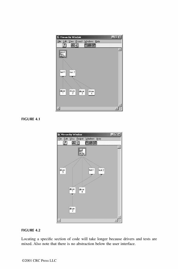
Locating a specific section of code will take longer because drivers and tests aremixed. Also note that there is no abstraction below the user interface.
FIGURE 4.1
FIGURE 4.2
©2001 CRC Press LLC
4.7 MAIN LEVEL
Let’s first look at the Main Level, which serves as the user interface and testexecutive. If the NI Test Executive is not being used, make the Main Level consistof a single VI. Only Test Level VIs are allowed to be called from this first tier. TheTest Level will then call the needed drivers for the specific operations. The MainLevel should avoid calling drivers because the abstraction benefits are diminished.Reuse is diminished when specific sections cannot be differentiated for copying andpasting methods. Furthermore, the code panel and hierarchy also become difficultto read and maintain. The use of application tiers aids reusability and readability.
The NI Test Executive serves as the Main Level and provides user interfacefunctions. It supplies the needed structure for adding application-specific tests, andoffers flexibility for changes. If you are using the Test Executive, you will alreadyhave the extent of partitioning available to gain the benefits of the three-tieredapproach. You will be supplying the test and driver level VIs to incorporate into theframework of the executive.
4.7.1 USER INTERFACE
The user interface is part of the main level. The user interface is significant becauseit is the means by which interaction and control of the program occur. LabVIEWprovides various tools for designing an effective front panel. Its graphical naturegives it an edge over other programs when it comes to the user interface. WithLabVIEW 5.0, ActiveX controls can now be used in addition to the basic controls.This section will provide some tips and examples for developing effective interfaces.
Since the Test Executive already has a user interface, you would no longer havethe responsibility of creating one. You may still need to customize the interface tosuit your specific situation. The Test Executive allows the operator to select the testsequence and control execution of the sequence through the interface. The resultsof the test sequence are shown in a display that also indicates pass or fail status.
4.7.1.1 User Interface Design
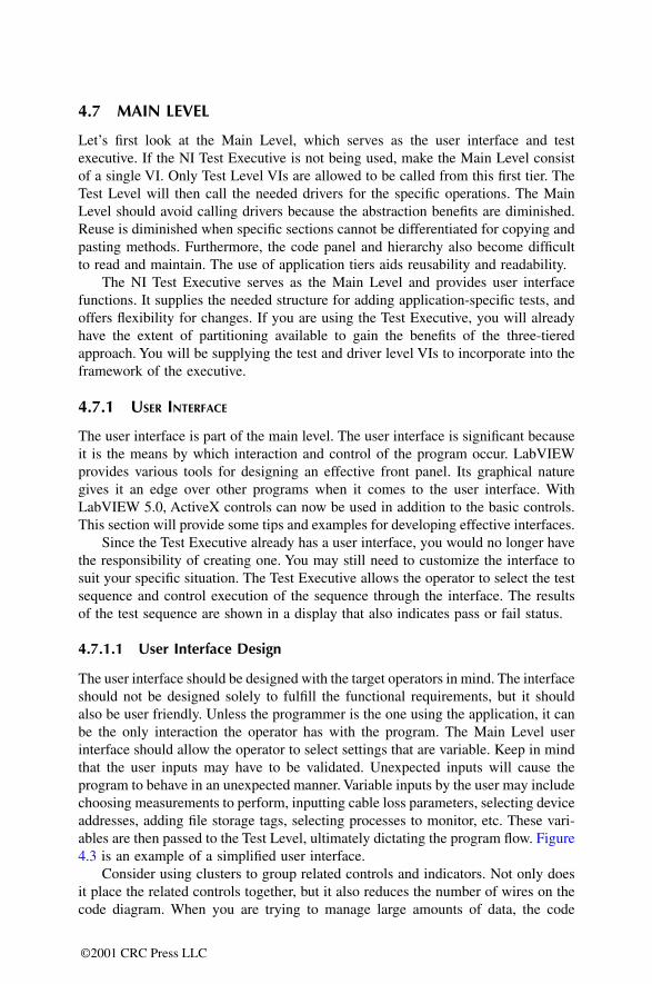
The user interface should be designed with the target operators in mind. The interfaceshould not be designed solely to fulfill the functional requirements, but it shouldalso be user friendly. Unless the programmer is the one using the application, it canbe the only interaction the operator has with the program. The Main Level userinterface should allow the operator to select settings that are variable. Keep in mindthat the user inputs may have to be validated. Unexpected inputs will cause theprogram to behave in an unexpected manner. Variable inputs by the user may includechoosing measurements to perform, inputting cable loss parameters, selecting deviceaddresses, adding file storage tags, selecting processes to monitor, etc. These vari-ables are then passed to the Test Level, ultimately dictating the program flow. Figure4.3 is an example of a simplified user interface.
Consider using clusters to group related controls and indicators. Not only doesit place the related controls together, but it also reduces the number of wires on thecode diagram. When you are trying to manage large amounts of data, the code
©2001 CRC Press LLC
diagram can get confusing with all of the wires of data being passed to VIs. Clusterscan be unbundled as needed, with only one wire representing the group of controlsotherwise. Even if you are not using clusters, try to use a frame decoration to groupthe controls for the user.
The user interface should utilize controls and displays that are appropriate forthe situation. If you are entering a cable loss, for example, you should use a digitalcontrol with the appropriate precision rather than a knob. This is more practicalbecause the value can be read and changed easily. Using descriptive labels is a goodway to differentiate the various front panel controls. Try not to clutter the main userinterface with controls or displays that are not needed. The person using the programcan easily get confused or lost if too many controls, indicators and decorations areused on the front panel of the user interface. The use of menus will help reduce theclutter, and will give the interface a nice appearance. Use buttons if the functionwill be used frequently; otherwise, use menus. Dialog controls are also good foruser interface functions.
Remember to give the user a way to cancel or abort execution. This is easy tooverlook, but is very important to an operator. Users need a way to stop in the middleof execution without having to use the Abort Execution button on the toolbar.
Graphs and charts are useful for displaying data. Sometimes just a glance at agraph can reveal a number of things, but graphs, charts, and other graphics shouldbe used only as needed. Graphing while acquiring data will not only slow theexecution of the program, but will take up more memory. Memory concerns willgrow as the number of VIS written for the application grows.
FIGURE 4.3
©2001 CRC Press LLC
4.7.1.2 Attribute Node Examples
You can use your imagination to develop a professional user interface. By usingattribute nodes, tabs can be created to alleviate the clutter that can result from toomany controls. Figure 4.4 is an example of a user interface that utilizes attributenodes. There are three sets of controls that can be accessed through the three buttonson the front panel cluster. When a button is pressed, the associated controls appearfor the user to manipulate.
Figure 4.5 shows what appears when the Instrument Addresses button is pressed.Figure 4.6 captures the code diagram and the implementation of the tabs. Attributenodes are used to make the controls visible or to hide them. Attribute nodes can becreated by popping up on the control from the code diagram. Select Create fromthe menu, then select Attribute Node. Once the attribute node has been created, thereare several attributes that can be selected, depending on the type of control beingused. The Visible attribute was used in the example. Some common attributes thatcan be manipulated include Visible, Disabled, Key Focus, Blinking, Position,Bounds, Caption, and Caption Visible.
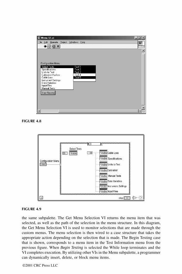
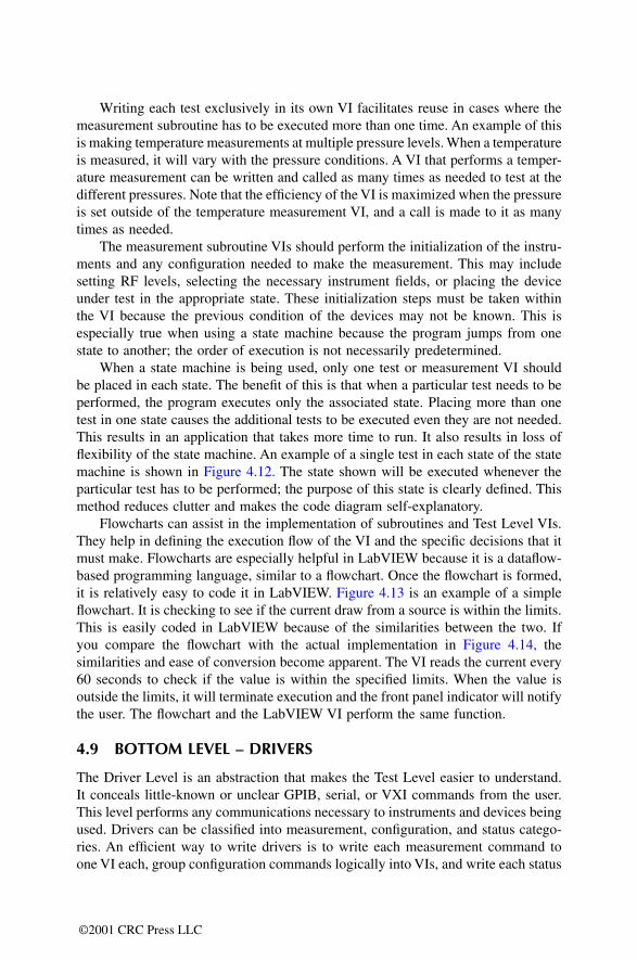
Using attribute nodes once again, Figure 4.7 is an example of a menu andsubmenus structure that is simple to implement. The front panel shown has the mainmenu that appears on the user interface panel. A Single Selection Listbox is usedfrom the List & Rings palette. Figure 4.8 shows the submenu that appears when thefirst item, Select Tests, is selected from the listbox. A Multiple Selection Listboxbecomes visible and allows the operator to select the tests that have to be executed.When all the needed settings have been completed, the user can hit the Start Testingbutton to begin execution of the tests.
Figure 4.9 is an illustration of the code diagram for this example. The casestructure is driven by the main menu selection. The structure is placed inside a mainWhile loop that will repeat until the Start Testing button is pressed. The VisibleAttribute node is used to make the submenus appear when a selection is made onthe main menu. Note that you must first set the Visible Attribute node for all of thesubmenus to “false” before the While loop starts.
4.7.1.3 Customizing Menus
LabVIEW run-time menus can be customized to suit specific needs by using theMenu Editor. The menus can be modified by selecting the Edit Menu item from theEdit menu. The drop-down box allows the programmer to select either the default,minimal, or custom menus to appear during VI execution. The default selectiondisplays the menus that are normally available while the program is not executing.The minimal selection is a subset of the default that appears during run-time. Thecustom selection requires the programmer to create a new menu structure and saveit as a real-time menu (*.rtm) file. Once a real-time menu file is created, it can beused for multiple VIs. A shortcut key combination can be specified for each menuitem that is created. The on-line help explains how to customize menus, includinghow to add User Items.
©2001 CRC Press LLC
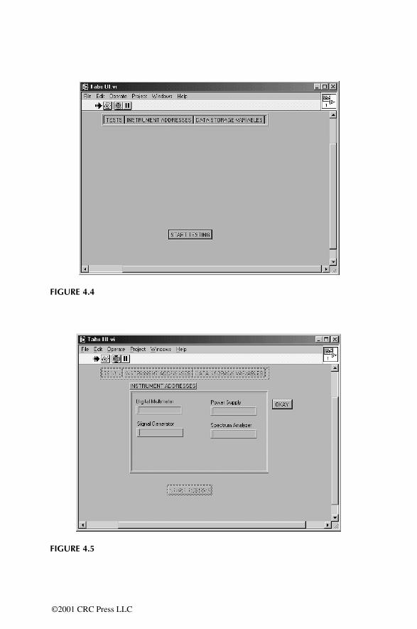
FIGURE 4.4
FIGURE 4.5
©2001 CRC Press LLC
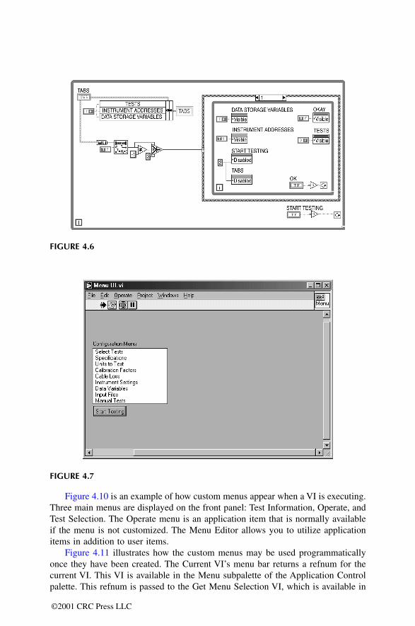
Figure 4.10 is an example of how custom menus appear when a VI is executing.Three main menus are displayed on the front panel: Test Information, Operate, andTest Selection. The Operate menu is an application item that is normally availableif the menu is not customized. The Menu Editor allows you to utilize applicationitems in addition to user items.
Figure 4.11 illustrates how the custom menus may be used programmaticallyonce they have been created. The Current VI’s menu bar returns a refnum for thecurrent VI. This VI is available in the Menu subpalette of the Application Controlpalette. This refnum is passed to the Get Menu Selection VI, which is available in
FIGURE 4.6
FIGURE 4.7
©2001 CRC Press LLC
©2001 CRC Press LLC
the same subpalette. The Get Menu Selection VI returns the menu item that wasselected, as well as the path of the selection in the menu structure. In this diagram,the Get Menu Selection VI is used to monitor selections that are made through thecustom menus. The menu selection is then wired to a case structure that takes theappropriate action depending on the selection that is made. The Begin Testing casethat is shown, corresponds to a menu item in the Test Information menu from theprevious figure. When Begin Testing is selected the While loop terminates and theVI completes execution. By utilizing other VIs in the Menu subpalette, a programmercan dynamically insert, delete, or block menu items.
FIGURE 4.8
FIGURE 4.9

4.7.2 EXCEPTION-HANDLING AT THE MAIN LEVEL
Error handling is one element of the project that is often overlooked or not wellimplemented. Planning for the possibility of something going wrong is difficult, butnecessary. A well-designed program will take into account that errors can and dooccur. Building exception handling into a program has several benefits. It is a wayto notify the operator something has gone wrong that needs attention. It is also veryuseful for troubleshooting and debugging purposes, as well as for finding out whereand why the problem occurred.
There are different ways to control the error situations that can arise. One wayis to let the program attempt to correct the problem and continue execution. Forerrors that cannot be corrected, the application may complete tests not dependenton the failed subsection. Another possibility would be to halt execution of theprogram and notify the user via a dialogue box, e-mail, or even a pager.
Error handling is an important task that should be managed in the Main Level.This forces all errors to be dealt with in one central place, allowing them to be
FIGURE 4.10
FIGURE 4.11
©2001 CRC Press LLC

managed better. The Main Level controls program flow and execution. The MainLevel should also determine the course of action when faults occur. When errorsare handled in several locations, or as they occur, program control may have to bepassed to lower levels and may be difficult to troubleshoot. Also, when errors arehandled in more than one location, the code for the handling may have to be repeated.
When a state machine is used, this significant task is made easy because onestate is assigned specifically for error handling. When errors are generated, the statemachine jumps to the Error state to determine the course of action. Based on theseverity of the fault that has occurred, the Error state in the Main Level will decidewhat will be done. If the error is minor, other states that might be affected will beparsed and the remaining will be executed. If it is major fault, the program willperform all closing duties and terminate execution in the normal manner whilenotifying the user of the error. Chapter 6 discusses exception handling in more detail.
Handling execution based on pass or fail criteria should also be considered. TheTest Executive lets the user specify the course of action when a test fails. You cancontinue to the next test, stop execution of the whole sequence, or repeat the sametest again. Dependencies can be created for the individual tests. A dependency, oncecreated, will execute a test based on the result of another test. The result can bedefined as either pass or fail.
4.8 SECOND LEVEL — TEST LEVEL
The Test Level is called by the Main Level, and the VIs in this level should bewritten on a stand-alone basis to allow reuse. Each Test Level VI should performone test or action only. The code should be broken up so that each test that needsto be performed can be written as a separate VI. When multiple tests are combinedin one VI, they are not easily reused because either the extra tests that are not neededwould have to be removed, or the extra tests must be executed unnecessarily. Thesesecond tier VIs are basically test and measurement subroutines, but can also includeconfiguration and dialog VIs.
FIGURE 4.12
©2001 CRC Press LLC
Writing each test exclusively in its own VI facilitates reuse in cases where themeasurement subroutine has to be executed more than one time. An example of thisis making temperature measurements at multiple pressure levels. When a temperatureis measured, it will vary with the pressure conditions. A VI that performs a temper-ature measurement can be written and called as many times as needed to test at thedifferent pressures. Note that the efficiency of the VI is maximized when the pressureis set outside of the temperature measurement VI, and a call is made to it as manytimes as needed.
The measurement subroutine VIs should perform the initialization of the instru-ments and any configuration needed to make the measurement. This may includesetting RF levels, selecting the necessary instrument fields, or placing the deviceunder test in the appropriate state. These initialization steps must be taken withinthe VI because the previous condition of the devices may not be known. This isespecially true when using a state machine because the program jumps from onestate to another; the order of execution is not necessarily predetermined.
When a state machine is being used, only one test or measurement VI shouldbe placed in each state. The benefit of this is that when a particular test needs to beperformed, the program executes only the associated state. Placing more than onetest in one state causes the additional tests to be executed even they are not needed.This results in an application that takes more time to run. It also results in loss offlexibility of the state machine. An example of a single test in each state of the statemachine is shown in Figure 4.12. The state shown will be executed whenever theparticular test has to be performed; the purpose of this state is clearly defined. Thismethod reduces clutter and makes the code diagram self-explanatory.
Flowcharts can assist in the implementation of subroutines and Test Level VIs.They help in defining the execution flow of the VI and the specific decisions that itmust make. Flowcharts are especially helpful in LabVIEW because it is a dataflow-based programming language, similar to a flowchart. Once the flowchart is formed,it is relatively easy to code it in LabVIEW. Figure 4.13 is an example of a simpleflowchart. It is checking to see if the current draw from a source is within the limits.This is easily coded in LabVIEW because of the similarities between the two. Ifyou compare the flowchart with the actual implementation in Figure 4.14, thesimilarities and ease of conversion become apparent. The VI reads the current every60 seconds to check if the value is within the specified limits. When the value isoutside the limits, it will terminate execution and the front panel indicator will notifythe user. The flowchart and the LabVIEW VI perform the same function.
4.9 BOTTOM LEVEL – DRIVERS
The Driver Level is an abstraction that makes the Test Level easier to understand.It conceals little-known or unclear GPIB, serial, or VXI commands from the user.This level performs any communications necessary to instruments and devices beingused. Drivers can be classified into measurement, configuration, and status catego-ries. An efficient way to write drivers is to write each measurement command toone VI each, group configuration commands logically into VIs, and write each status
©2001 CRC Press LLC
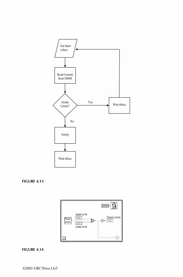
FIGURE 4.13
FIGURE 4.14
©2001 CRC Press LLC
command to one VI. As an example of this driver architecture, examine the HP8920Adriver set by National Instruments.
Simply put, measurement drivers are used to perform a measurement. One VIshould be used to perform one measurement to maximize the reuse of the VI. Bywriting measurement drivers in this manner, the driver can be called in the sameapplication for different cases, or in a different application where the same measure-ment needs to be performed. If more than one measurement is grouped into a singleVI, either one of the measurements must be stripped out for reuse or other measure-ments will have to be performed unnecessarily.
Configuration drivers set up the instrument to make a measurement or placeit in known state at the start of an application. Configuration commands can begrouped logically in VIs. When a measurement has to be performed, usually morethan one configuration command is needed to prepare the instrument. Sometimesmany parameters have to be configured for a single test. Writing one configu-ration command to a VI would create difficulty in maintenance because of thenumber of VIs that will result. Grouping the configuration commands accordingto the type of measurement will minimize the number of VIs on the Driver Level.In addition, memory space can also be used more efficiently by following thisstyle.
Drivers can range from very simple to very complicated, depending on theinstruments being used. A driver for a power supply might only need a few param-eters and commands, but an instrument like a communication analyzer might haveupwards of 100 different commands. In this case you must group configurationcommands to reduce the number of VI drivers that need to be written.
Status drivers simply check the state of an instrument by reading status registers.These are usually written as needed, one to a VI. An example of a status driver isa register that holds the current state of a particular measurement. One bit will beset if the measurement is under progress, and cleared when it is finished. You mustensure that the measurement is finished before reading the value so the status registeris checked. Remember that drivers can be created for other types of communicationneeds as well.
If you need to use TCP, DDE, ActiveX, or PPC, you can use a similar logicwhen developing the lower layer of the application. When VIs are created to performa specific action, configuration, or status inquiry, they can be reused easily.
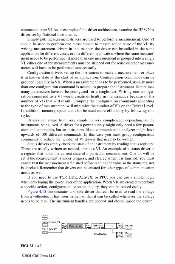
Figure 4.15 demonstrates a simple driver that can be used to read the voltagefrom a voltmeter. It has been written so that it can be called whenever the voltageneeds to be read. The instrument handles are opened and closed inside the driver.
FIGURE 4.15
©2001 CRC Press LLC
4.10 STYLE TIPS
We have seen numerous applications in the past few years that do not incorporategood practices that could increase the efficiency, readability, maintainability, andreuse of the code that has been developed. Most of this chapter covers topics toassist the reader in developing successful applications by revealing the programmingstyle that has been effective for the authors. This section was intended to providemore tips on programming, this time by uncovering inefficient programming stylesand common pitfalls that can be avoided.
4.10.1 SEQUENCE STRUCTURES
The first inefficient programming style is a result of the overuse of sequence struc-tures in the code diagram. Sequence structures were described in Chapter 1 in detail.The main purpose of the sequence structure is to control the execution order of thecode. Code that must execute first is placed in the first frame, and then pieces ofthe code are placed in the appropriate frame in the order that execution is desired.If your code is data-dependent, however, sequence structures are not needed. Theexecution order is forced by dataflow; VIs will execute when the data they needbecomes available to them.
Overuse of sequence structures is the consequence of not utilizing the structuresas they were intended. We have seen VIs that contained sequence structures with 50or more frames. When the architecting or design phase of the application is omitted,an application with so many frames can be an outcome. It signals that perhaps theVI is performing too many actions and that subVIs are not being used sufficiently.When too many actions are performed, the code that is developed is no longermodular. Lack of modularity hampers the ability to reuse code. Consider using thethree-tiered structure approach to your application if your sequence structures havetoo many frames. The use of subVIs for tests and subroutines will reduce the needfor many frames while increasing the ability to reuse code. The frames in thesequence structure can be easily modularized into VIs. At the same time, the codewill become more readable and maintainable. By developing the description of logicfor the VIs during the design phase, you can determine what each VI should do aspart of the whole application.
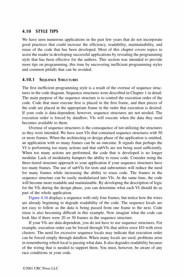
Figure 4.16 displays a sequence with only four frames, but notice how the wiresare already beginning to degrade readability of the code. The sequence locals arenot easy to follow as the data is being passed from one frame to the next. Codereuse is also becoming difficult in this example. Now imagine what the code canlook like if there were 20 or 30 frames in the sequence structure.
If your VIs are data-dependent, you do not have to use sequence structures. Forexample, execution order can be forced through VIs that utilize error I/O with errorclusters. The need for excessive sequence locals may indicate that execution ordercan be forced simply through dataflow. When many locals are used, problems arisein remembering which local is passing what data. It also degrades readability becauseof the wiring that is needed to support them. You must, however, be aware of anyrace conditions in your code.
©2001 CRC Press LLC
4.10.2 NESTED STRUCTURES
Nested case structures, sequence structures, For loops, and While loops are some-times necessary in the code diagram to accomplish a task. However, creating toomany levels of nested structures can lead to inefficient code that lacks modularityand readability. The arguments presented previously on the use of sequence struc-tures apply to the use of nested structures.
Try to avoid nesting your structures more than three levels deep. When too manylevels of nesting are used, the code becomes difficult to read. Data wires beingpassed into and out of the structures are not easy to follow and understand. Whencase structures are being used, you must look at each case to determine how thedata is being handled. This, along with the use of sequence locals or shift registers,For loops, and sequence structures, adds to the readability problem.
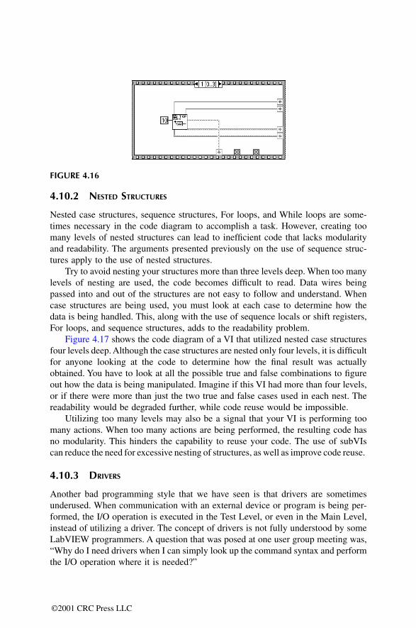
Figure 4.17 shows the code diagram of a VI that utilized nested case structuresfour levels deep. Although the case structures are nested only four levels, it is difficultfor anyone looking at the code to determine how the final result was actuallyobtained. You have to look at all the possible true and false combinations to figureout how the data is being manipulated. Imagine if this VI had more than four levels,or if there were more than just the two true and false cases used in each nest. Thereadability would be degraded further, while code reuse would be impossible.
Utilizing too many levels may also be a signal that your VI is performing toomany actions. When too many actions are being performed, the resulting code hasno modularity. This hinders the capability to reuse your code. The use of subVIscan reduce the need for excessive nesting of structures, as well as improve code reuse.
4.10.3 DRIVERS
Another bad programming style that we have seen is that drivers are sometimesunderused. When communication with an external device or program is being per-formed, the I/O operation is executed in the Test Level, or even in the Main Level,instead of utilizing a driver. The concept of drivers is not fully understood by someLabVIEW programmers. A question that was posed at one user group meeting was,“Why do I need drivers when I can simply look up the command syntax and performthe I/O operation where it is needed?”
FIGURE 4.16
©2001 CRC Press LLC
There are definite advantages that can be gained by creating and using drivers.The abstraction that drivers provide is a notable benefit for the application. Theactual communication and command syntax is hidden from those who do not needor wish to see this code. This also improves the readability of the code when theseobscure operations are not mixed with the Main and Test Level VIs.
The use of drivers also facilitates reuse of code. When drivers are not used, theactual code that performs the communication is difficult to reuse because it is partof another VI. Cutting and pasting part of the code is not as easy as inserting a newVI. However, when drivers are written to perform specific actions, they can be reusedeasily in any application by inserting the driver VI. Drivers must be developed in away that will simplify its reuse. A thorough discussion on drivers and driver devel-opment is presented in Chapter 5.
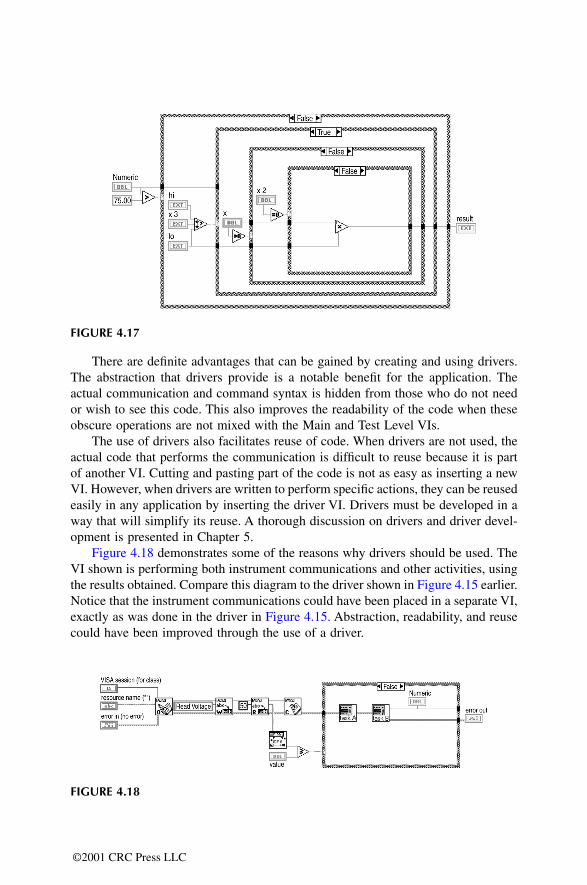
Figure 4.18 demonstrates some of the reasons why drivers should be used. TheVI shown is performing both instrument communications and other activities, usingthe results obtained. Compare this diagram to the driver shown in Figure 4.15 earlier.Notice that the instrument communications could have been placed in a separate VI,exactly as was done in the driver in Figure 4.15. Abstraction, readability, and reusecould have been improved through the use of a driver.
FIGURE 4.17
FIGURE 4.18
©2001 CRC Press LLC
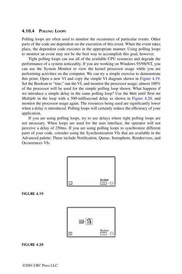
4.10.4 POLLING LOOPS
Polling loops are often used to monitor the occurrence of particular events. Otherparts of the code are dependent on the execution of this event. When the event takesplace, the dependent code executes in the appropriate manner. Using polling loopsto monitor an event may not be the best way to accomplish this goal, however.
Tight polling loops can use all of the available CPU resources and degrade theperformance of a system noticeably. If you are working on Windows 95/98/NT, youcan use the System Monitor to view the kernel processor usage while you areperforming activities on the computer. We can try a simple exercise to demonstratethis point. Open a new VI and copy the simple VI diagram shown in Figure 4.19.Set the Boolean to “true,” run the VI, and monitor the processor usage; almost 100%of the processor will be used for the simple polling loop shown. What happens ifwe introduce a simple delay in the same polling loop? Use the Wait until Next msMultiple in the loop with a 500-millisecond delay as shown in Figure 4.20, andmonitor the processor usage again. The resources being used are significantly lowerwhen a delay is introduced. Polling loops will certainly reduce the efficiency of yourapplication.
If you are using polling loops, try to use delays where tight polling loops arenot necessary. When loops are used for the user interface, the operator will notperceive a delay of 250ms. If you are using polling loops to synchronize differentparts of your code, consider using the Synchronization VIs that are available in theAdvanced palette. These include Notification, Queue, Semaphore, Rendezvous, andOccurrences VIs.
FIGURE 4.19
FIGURE 4.20
©2001 CRC Press LLC
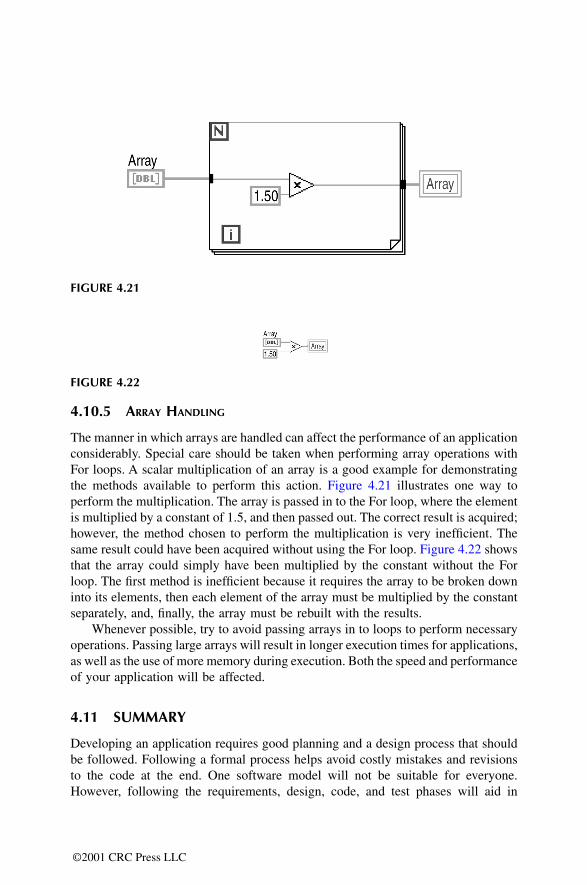
4.10.5 ARRAY HANDLING
The manner in which arrays are handled can affect the performance of an applicationconsiderably. Special care should be taken when performing array operations withFor loops. A scalar multiplication of an array is a good example for demonstratingthe methods available to perform this action. Figure 4.21 illustrates one way toperform the multiplication. The array is passed in to the For loop, where the elementis multiplied by a constant of 1.5, and then passed out. The correct result is acquired;however, the method chosen to perform the multiplication is very inefficient. Thesame result could have been acquired without using the For loop. Figure 4.22 showsthat the array could simply have been multiplied by the constant without the Forloop. The first method is inefficient because it requires the array to be broken downinto its elements, then each element of the array must be multiplied by the constantseparately, and, finally, the array must be rebuilt with the results.
Whenever possible, try to avoid passing arrays in to loops to perform necessaryoperations. Passing large arrays will result in longer execution times for applications,as well as the use of more memory during execution. Both the speed and performanceof your application will be affected.
4.11 SUMMARY
Developing an application requires good planning and a design process that shouldbe followed. Following a formal process helps avoid costly mistakes and revisionsto the code at the end. One software model will not be suitable for everyone.However, following the requirements, design, code, and test phases will aid in
FIGURE 4.21
FIGURE 4.22
©2001 CRC Press LLC

developing applications. The structure of the application, which is decided on duringthe design phase, is an essential piece of the process. It will determine many crucialaspects of the program. The three-tiered approach, as described, embodies the desiredcharacteristics of most applications: the ability to make future modifications, theability to add features, ease of maintenance, the ability to reuse code, and providinglayers of abstraction. When the strict partitioning of levels is used in conjunctionwith the state machine, all the characteristics are further enhanced.
A summary example will help in applying the topics and ideas presented in thischapter. Suppose that Company A is involved in the sale and production of WidgetA. Let’s follow the steps that would be required to develop an application that wouldbe used in testing the widgets to determine if they meet specifications.
This first step involves defining the requirements for the test program. The goalof this application must be defined before beginning to code. After discussing theprogram with the appropriate people you enumerate the following requirements:
1. Parameters H, W, and D are to be tested using instruments H, W, and D,respectively.
2. The operator will be a factory technician and will need the flexibility toselect individual tests as needed.
3. The program should alert the operator when one of the widgets is out ofspecification limits.
4. There should be provisions for the addition of tests; measuring ParameterZ using Instrument Z is in the foreseeable future.
5. Company A is planning to produce Widget B next year, which will betested for its H, W, and several other parameters.
FIGURE 4.23
©2001 CRC Press LLC
The next step is to decide on the structure of the program. We will utilize the three-tiered approach and take advantage of the benefits it provides. The user interface ofthis application should be simple but flexible enough to provide the operator thelevel of control needed. Figure 4.23 shows what the User Interface looks like forthis application.
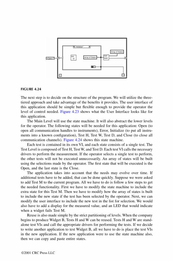
The Main Level will use the state machine. It will also abstract the lower levelsfor the operator. The following states will be needed for this application: Open (toopen all communication handles to instruments), Error, Initialize (to put all instru-ments into a known configuration), Test H, Test W, Test D, and Close (to close allcommunication channels). Figure 4.24 shows this state machine.
Each test is contained in its own VI, and each state consists of a single test. TheTest Level is composed of Test H, Test W, and Test D. Each test VI calls the necessarydrivers to perform the measurement. If the operator selects a single test to perform,the other tests will not be executed unnecessarily. An array of states will be builtusing the selections made by the operator. The first state that will be executed is theOpen, and the last state is the Close.
The application takes into account that the needs may evolve over time. Ifadditional tests have to be added, that can be done quickly. Suppose we were askedto add Test M to the current program. All we have to do is follow a few steps to getthe needed functionality. First we have to modify the state machine to include theextra state for this Test M. Then we have to modify how the array of states is builtto include the new state if the test has been selected by the operator. Next, we canmodify the user interface to include the new test in the list for selection. We wouldalso have to add a display for the measured value, and an LED that would indicatewhen a widget fails Test M.
Reuse is also made simple by the strict partitioning of levels. When the companybegins to produce Widget B, Tests H and W can be reused. Tests H and W are stand-alone test VIs and call the appropriate drivers for performing the tests. If we decideto write another application to test Widget B, all we have to do is place the test VIsin the new application. If the new application were to use the state machine also,then we can copy and paste entire states.
FIGURE 4.24
Open
"Initialize"
Array of States
Array of States
nextstate
init. VI
T
i
?
©2001 CRC Press LLC
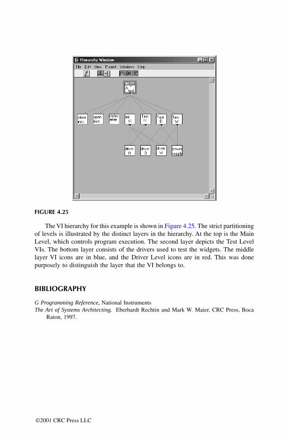
The VI hierarchy for this example is shown in Figure 4.25. The strict partitioningof levels is illustrated by the distinct layers in the hierarchy. At the top is the MainLevel, which controls program execution. The second layer depicts the Test LevelVIs. The bottom layer consists of the drivers used to test the widgets. The middlelayer VI icons are in blue, and the Driver Level icons are in red. This was donepurposely to distinguish the layer that the VI belongs to.
BIBLIOGRAPHY
G Programming Reference, National InstrumentsThe Art of Systems Architecting. Eberhardt Rechtin and Mark W. Maier, CRC Press, Boca
Raton, 1997.
FIGURE 4.25
©2001 CRC Press LLC

![THE ROSICRUCIAN FELLOWSHIP › ssoc › 1909__heindel___why_i_am_a_rosicrucian.pdf · JUI]v 3](https://static.documents.pub/doc/80x56/60cd02fa40fb275f0a1377d9/the-rosicrucian-a-ssoc-a-1909heindelwhyiamarosicrucianpdf-juiv.jpg)


![ponts en maçonnerie. constitution et stabilité [3 tomes] (jui 1982)_2](https://static.documents.pub/doc/80x56/5572008c49795991699f9fd5/ponts-en-maconnerie-constitution-et-stabilite-3-tomes-jui-19822-55ab58c50db9d.jpg)
