Order toll-free in the U.S.: Call 877-877-BBOX (outside U.S. call 724-746-5500) FREE technical support 24 hours a day, 7 days a week: Call 724-746-5500 or fax 724-746-0746 Mailing address: Black Box Corporation, 1000 Park Drive, Lawrence, PA 15055-1018 Web site: www.blackbox.com • E-mail: [email protected]CUSTOMER SUPPORT INFORMATION MARCH 1997 IC027A-R2 IC027AE-R2 488 Controller TALK LISTEN SRQ ERROR POWER
Transcript
Order toll-free in the U.S.: Call 877-877-BBOX (outside U.S. call 724-746-5500)FREE technical support 24 hours a day, 7 days a week: Call 724-746-5500 or fax 724-746-0746Mailing address: Black Box Corporation, 1000 Park Drive, Lawrence, PA 15055-1018Web site: www.blackbox.com • E-mail: [email protected]
CUSTOMER SUPPORT
INFORMATION
MARCH 1997IC027A-R2
IC027AE-R2
488 Controller
TALKLISTEN
SRQERROR POWER
488 CONTROLLER
3
EUROPEAN UNION DECLARATION OF CONFORMITYTo maintain safety, emission, and immunity standards of this declaration, the following conditions must be met.
• Serial and IEEE cables must have a braided shield connected circumferentially to their connectors’metal shells.
• All cable screw locks must be tightened at both ends of the cable.
• The host computer must be properly grounded.
• Some inaccuracy is to be expected when I/O leads are exposed to RF fields or transients.
• The operator must observe all safety cautions and operating conditions specified in the documentationfor all hardware used.
• The host computer, peripheral equipment, power sources, and expansion hardware must be CEcompliant.
• All power must be off to the device and externally connected equipment before internal access to thedevice is permitted.
• An external power supply is provided with this product. Its input is 105 to 125 VAC or 210 to 250 VAC,50-60 Hz, 10 VA maximum power draw. Its 9-VDC output connects to the power input of the unit(marked 10VDC MAX @ 500 mA).
• The RS-232/422 terminal is meant to be connected only to devices with serial-communications-levelsignals. The IEEE 488 terminal is meant to be used only with non-isolated IEEE 488 systems. Thecommon mode voltage (cable shell to earth) must be zero.
• Terminal Installation Category for CE Compliance is Category 1.
• Operating environment for CE compliance is: Indoor use at altitudes below 2000 m, 0 to 40°C, 80%maximum RH up to 31°C decreasing linearly 4%RH/°C to 40°C.
• Regarding DC power input: Please note that the power input is marked 10VDC MAX @ 600 mA. This is just something to check; check your equipment’s power input labels for “600 mA” (or even 500 mA).
WARNING!Noted conditions pertain to potential safety hazards. When you see the WARNING!,IMPORTANT!, or CAUTION! notes, carefully read the information and be alert to thepossibility of personal injury.
Failure to follow these directives voids emissions and immunity compliance.
3.3.1 Serial Baud Rate............................................................................................................................143.3.2 Serial Word Length (Data Bits)....................................................................................................153.3.3 Serial Stop Bits ..............................................................................................................................163.3.4 Serial Parity....................................................................................................................................163.3.5 Serial Echo.....................................................................................................................................173.3.6 Serial Handshake ..........................................................................................................................17
3.4 Selecting Terminator Substitution ..........................................................................................................183.4.1 Serial Terminator ..........................................................................................................................183.4.2 IEEE Bus Terminator ....................................................................................................................19
3.5 Selecting the Mode ..................................................................................................................................193.6 Selecting the IEEE Address .....................................................................................................................203.7 Feature Selections ....................................................................................................................................21
3.7.1 Controller Pass-Thru Features .....................................................................................................213.7.2 Peripheral Pass-Thru Features .....................................................................................................22
3.8 Serial Interface .........................................................................................................................................223.8.1 RS-232/RS-422 Signal Level Selection.........................................................................................223.8.2 Serial Signal Descriptions .............................................................................................................233.8.3 Serial-Cable Wiring Diagrams ......................................................................................................24
3.9 General Operation ...................................................................................................................................263.10 Is Anyone Out There? ............................................................................................................................27
4. IEEE Operating Modes ...................................................................................................................................284.1 Introduction .............................................................................................................................................284.2 Operating Mode Transitions ...................................................................................................................284.3 System Controller Mode ..........................................................................................................................304.4 System Controller, Not Active Controller Mode ....................................................................................314.5 Not System Controller Mode...................................................................................................................334.6 Active Controller, Not System Controller Mode ....................................................................................344.7 Controller Pass-Thru Mode .....................................................................................................................344.8 Peripheral Pass-Thru Mode .....................................................................................................................34
5.2.1 Syntax.............................................................................................................................................365.2.2 Response........................................................................................................................................385.2.3 Mode ..............................................................................................................................................385.2.4 Bus States .......................................................................................................................................39
5.3 Memory Use..............................................................................................................................................405.4 The Commands ........................................................................................................................................40
6. Controller Pass-Thru Operation.....................................................................................................................746.1 Introduction .............................................................................................................................................746.2 Serial and IEEE Terminator Substitution ...............................................................................................746.3 IEEE Address Selection............................................................................................................................756.4 Talk Back on Terminator .........................................................................................................................756.5 Plotter Applications..................................................................................................................................766.6 Printer Applications .................................................................................................................................78
7. Peripheral Pass-Thru Operation ....................................................................................................................797.1 Introduction .............................................................................................................................................797.2 Serial and IEEE Input Buffers .................................................................................................................797.3 IEEE Data Transfers .................................................................................................................................80
7.3.1 Blind Bus Data Transfers ..............................................................................................................807.3.2 Controlled Bus Data Transfers .....................................................................................................81
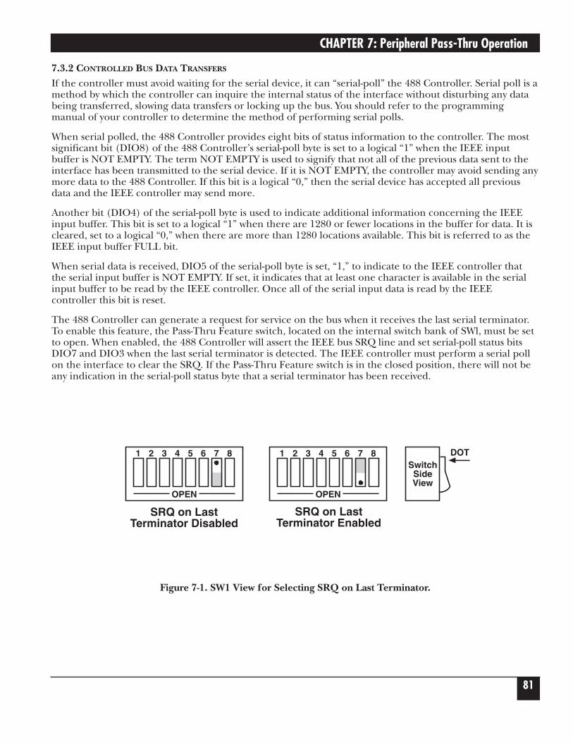
7.4 Serial Poll Status Byte Register ................................................................................................................827.5 Use of Serial and Bus Terminators..........................................................................................................837.6 IEEE 488 Bus Implementation ................................................................................................................83
7.6.1 My Talk Address (MTA)................................................................................................................837.6.2 My Listen Address (MLA) ............................................................................................................837.6.3 Device Clear (DCL and SDC) ......................................................................................................847.6.4 Interface Clear (IFC)....................................................................................................................847.6.5 Serial Poll Enable (SPE) ...............................................................................................................847.6.6 Serial Poll Disable (SPD)..............................................................................................................847.6.7 Unlisten (UNL).............................................................................................................................847.6.8 Untalk (UNT) ...............................................................................................................................84
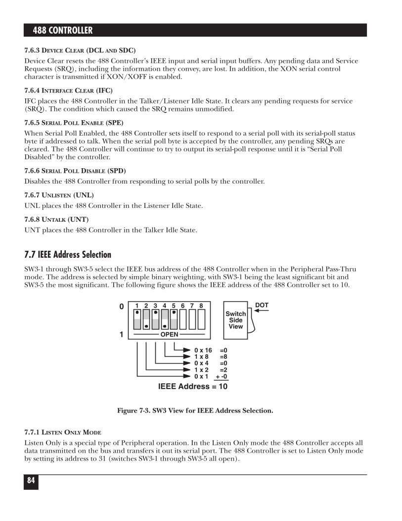
7.7 IEEE Address Selection............................................................................................................................847.7.1 Listen Only Mode .........................................................................................................................84
8. IEEE 488 Primer..............................................................................................................................................858.1 History.......................................................................................................................................................858.2 General Structure.....................................................................................................................................858.3 Send It To My Address .............................................................................................................................878.4 Bus Management Lines............................................................................................................................87
8.4.1 Attention (ATN) ...........................................................................................................................878.4.2 Interface Clear (IFC)....................................................................................................................878.4.3 Remote Enable (REN)..................................................................................................................878.4.4 End or Identify (EOI)...................................................................................................................878.4.5 Service Request (SRQ) .................................................................................................................87
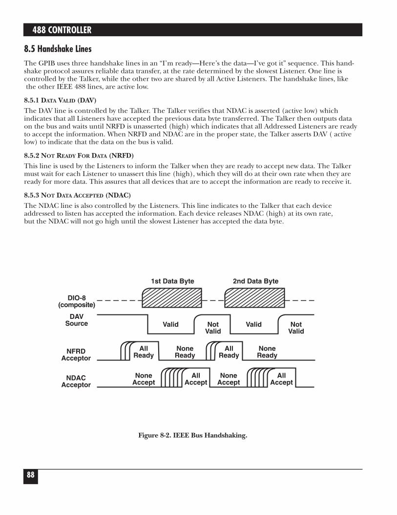
8.5 Handshake Lines......................................................................................................................................888.5.1 Data Valid (DAV) ..........................................................................................................................888.5.2 Not Ready For Data (NRFD)........................................................................................................888.5.3 Not Data Accepted (NDAC).........................................................................................................88
8.6 Data Lines .................................................................................................................................................89
CONTENTS
7
Chapter Page
8.7 Multiline Commands ...............................................................................................................................898.7.1 Go To Local (GTL).......................................................................................................................898.7.2 Listen Address Group (LAG).......................................................................................................898.7.3 Unlisten (UNL).............................................................................................................................898.7.4 Talk Address Group (TAG) ..........................................................................................................898.7.5 Untalk (UNT) ...............................................................................................................................898.7.6 Local Lockout (LLO) ...................................................................................................................898.7.7 Device Clear (DCL) ......................................................................................................................898.7.8 Selected Device Clear (SDC)........................................................................................................898.7.9 Serial Poll Disable (SPD)..............................................................................................................898.7.10 Serial Poll Enable (SPE) .............................................................................................................898.7.11 Group Execute Trigger (GET)...................................................................................................898.7.12 Take Control (TCT)....................................................................................................................898.7.13 Secondary Command Group (SCG)..........................................................................................908.7.14 Parallel Poll Configure (PPC)....................................................................................................908.7.15 Parallel Poll Unconfigure (PPU) ...............................................................................................90
8.8 More On Service Requests.......................................................................................................................908.8.1 Serial Poll.......................................................................................................................................908.8.2 Parallel Poll....................................................................................................................................90
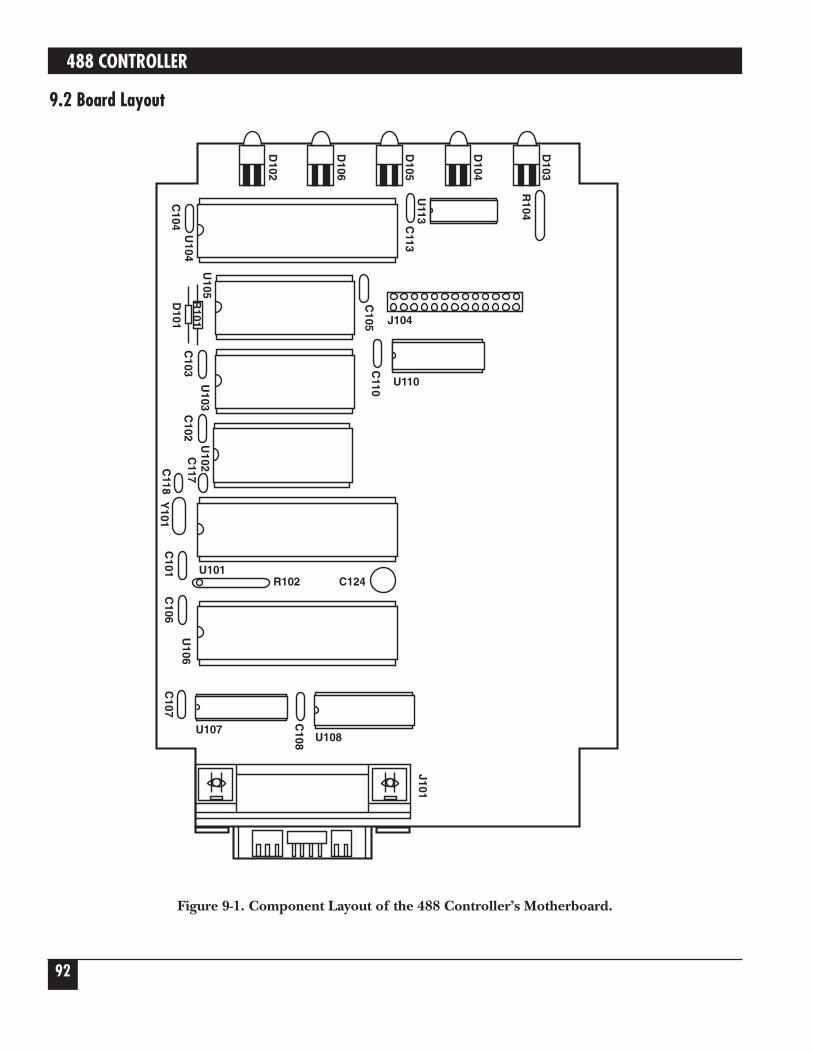
9. Theory of Operation & Board Layout ...........................................................................................................919.1 Theory of Operation................................................................................................................................919.2 Board Layout ............................................................................................................................................92
Index ...................................................................................................................................................................103
TRADEMARKS USED IN THIS MANUAL
Macintosh® is a registered trademark of Apple Computer, Inc.
Hewlett-Packard® and HP® are registered trademarks of Hewlett-Packard.
AT® and IBM® are registered trademarks of IBM Corporation.
All applied-for and registered trademarks are the property of their respective owners.
Data Buffer — 32,000 characters total, dynamically allocated.
Indicators — LEDs for Talk, Listen, SRQ, Error and Power
Power — 105-125V or 210-250V; 50-60 Hz, 10 VA Max.
Size — 2.7"H x 5.5"W x 7.4"D (6.9 x 14 x 18.8 cm)
Weight — 3.6 lb. (1.6 kg)
Environment — 0 to 50 degrees Centigrade; 0 to 70% R.H. to 35 degreesCentigrade. Linearly derate 3% R.H./degrees Centigradefrom 35 to 50 degrees Centigrade.
Controls — Power Switch (external), IEEE and Serial parameter switches(internal). Jumper selection of RS-232 or RS-422 operation(internal).
Certification — FCC, CE
WARNING!Do not use this interface outdoors. The interface is intended for indoor use only. Using thisequipment outdoors could result in equipment failure, bodily injury, or death.
CAUTIONDo not connect AC line power directly to the 488 Controller. Direct AC connection willdamage equipment.
488 CONTROLLER
10
2.1 DescriptionThe 488 Controller converts a host RS-232 or RS-422 computer into an IEEE 488 bus talker, listener andcontroller. The 488 Controller provides full IEEE 488-1978 bus implementation including advancecapabilities such as PASS CONTROL, RECEIVE CONTROL, PARALLEL POLL, SERIAL POLL andSECONDARY ADDRESSING. The device may be located several hundred feet from the host and maycontrol as many as fourteen 488 bus instruments. In the noncontroller mode the 488 Controller converts the host into a bus peripheral for data processing and mass storage.
The 488 Controller interprets simple high-level commands sent from the computer’s serial port andperforms the necessary, and usually complex, bus control and handshaking. The commands and protocolare similar to those used by the Hewlett-Packard® HP-85 computer.
Additional features provide a transparent IEEE to serial converter and a serial to IEEE pass-thru controller.
As a serial-to-IEEE-488 converter, the 488 Controller receives data from a serial host, then automaticallyperforms the bus sequences necessary to send this data to the IEEE 488 device. If desired, data can berequested from the IEEE 488 device and returned to the host.
As an IEEE-488-to-serial converter, the 488 Controller is a peripheral to an IEEE 488 controller. Datareceived from the controller is sent to the serial device and data received from the serial device is bufferedfor transmission to the IEEE 488 controller. The 488 Controller can inform the host, by the serial poll-statusbyte, that it has received data from the serial device.
2. Introduction
CHAPTER 2: Introduction
11
2.2 AbbreviationsThe following IEEE 488 abbreviations are used throughout this manual.
addr n IEEE bus address “n”
ATN Attention line
CA Controller Active
CO Controller
CR Carriage Return
data Data String
DCL Device Clear
GET Group Execute Trigger
GTL Go To Local
LA Listener Active
LAG Listen Address Group
LF Line Feed
LLO Local Lock Out
MLA My Listen Address
MTA My Talk Address
PE Peripheral
PPC Parallel Poll Configure
PPU Parallel Poll Unconfigure
REN Remote Enable
SC System Controller
SDC Selected Device Clear
SPD Serial Poll Disable
SPE Serial Poll Enable
SRQ Service Request
TA Talker Active
TAD Talker Address
TCT Take Control
term Terminator
UNL Unlisten
UNT Untalk
* Unasserted
488 CONTROLLER
12
3.1 InspectionThe 488 Controller was carefully inspected, both mechanically and electrically, prior to shipment. When you receive it carefully unpack all items from the shipping carton and check for any obvious signs of damagethat may have occurred during shipment. Immediately report any damage found to the shipping agent.Remember to retain all shipping materials in the event that shipment back to the factory becomes necessary.
Every 488 Controller is shipped with the following:
• 488 Controller
• This instruction manual
• Power supply
3.2 ConfigurationThree DIP switches internal to the 488 Controller set the configuration of the interface.
NOTESelectable functions are read only at power-on and should only be set prior to applyingpower to the interface.
The following figures illustrate the factory default conditions, which are:
Serial Port: IEEE:
9600 Baud Mode = System Controller
8 Data Bits Address = 10
2 Stop Bits Bus Terminator = CR-LF; EOI Disabled
No Parity Talk-back Enabled
Serial Terminator = CR-LF
Echo Disabled
RTS/CTS Handshake
3. Getting Started
CHAPTER 3: Getting Started
13
Figure 3-1. SW3 Factory-Default Settings.
Figure 3-2. SW2 Factory-Default Settings.
Figure 3-3. SW1 Factory-Default Settings.
1 2 3 4 5 6 7 8
OPEN
SW
1
Baud RateHandshake
Word Length
9600RTS/CTS8 Data Bits
SwitchSideView
DOT
Pass-Thru Feature Enabled
Stop Bits 2 Stop Bits
1 2 3 4 5 6 7 8
OPEN
SW
2
ModeSerial Term
Echo
SCCR-LF
SwitchSideView
DOT
Parity
No EchoNo Parity
1 2 3 4 5 6 7 8
OPEN
SW
3
IEEE AddrIEEE Term
EOI
10CR-LFDisabled
SwitchSideView
DOT
488 CONTROLLER
14
Note that the 488 Controller comes configured as an IEEE controller. In this mode the 488 Controller isdesigned to allow an RS-232 host computer to control up to 14 IEEE 488 devices. This mode of operation is described in detail, along with its command descriptions, in Chapters 4 and 5. These sections also coverthe peripheral mode of operation.
The 488 Controller can be configured to transparently communicate with a single IEEE peripheral, such as a plotter. This Controller Pass-Thru mode is described in detail in Chapter 6.
The 488 Controller may also be configured as a transparent IEEE Pass-Thru Peripheral. As a Pass-ThruPeripheral, it allows an IEEE controller to communicate with an RS-232 device. The Peripheral Pass-Thrumode of operation is described in detail in Chapter 7.
To modify any of these defaults, follow this simple procedure:
1) Disconnect the power supply from the AC line and from the 488 Controller. Also disconnect any IEEE or serial cables prior to disassembly.
WARNINGNever open the 488 Controller’s case while it is connected to the AC line. Failure toobserve this warning may result in equipment failure, personal injury or death.
2) Place the 488 Controller upside down on a flat surface. Remove the four screws located near the rubberfeet.
3) Return the interface to the upright position and carefully remove the top cover.
4) Change whichever DIP-switch settings you need to change.
5) When you have made all of your changes, reverse this procedure to reassemble the 488 Controller.
3.3 Serial-Port SettingsThe first parameters to configure are those that correspond to the RS-232 port. These include baud rate,word length, number of stop bits, parity selection and type of RS-232 handshake. Each of these is describedin the following sections.
3.3.1 SERIAL BAUD RATE
The “baud rate” is the number of serial bits per second transferred into and out of the serial interface. SW1-1 through SW1-4 determine the serial baud rate. The factory-default baud rate is 9600 baud. Baud rates maybe selected from 110 to 57,600 baud. Refer to the following diagram for specific baud rates.
CHAPTER 3: Getting Started
15
Figure 3-4. Switch SW1: Selecting the Serial Baud Rate.
3.3.2 SERIAL WORD LENGTH (DATA BITS)SW1-6 determines the number of data bits, often referred to as word length, for each serial charactertransmitted or received. The factory default is 8 data bits.
Figure 3-5. Switch SW1: Selecting the Serial Word Length (Data Bits).
1 2 3 4 5 6 7 8
OPEN
8 Data Bits
1 2 3 4 5 6 7 8
OPEN
7 Data Bits
SwitchSideView
DOT
SwitchSideView
DOT
110
1 2 3 4 5 6 7 8
OPEN
1 2 3 4 5 6 7 8
OPEN
1800
300
1 2 3 4 5 6 7 8
OPEN
110
1 2 3 4 5 6 7 8
OPEN
1 2 3 4 5 6 7 8
OPEN
2400
110
1 2 3 4 5 6 7 8
OPEN
1 2 3 4 5 6 7 8
OPEN
3600
1 2 3 4 5 6 7 8
OPEN
4800135
1 2 3 4 5 6 7 8
OPEN
1 2 3 4 5 6 7 8
OPEN
720015 0
1 2 3 4 5 6 7 8
OPEN
1 2 3 4 5 6 7 8
OPEN
9600
600
1 2 3 4 5 6 7 8
OPEN
1 2 3 4 5 6 7 8
OPEN
19,200
1200
1 2 3 4 5 6 7 8
OPEN
1 2 3 4 5 6 7 8
OPEN
57,600
488 CONTROLLER
16
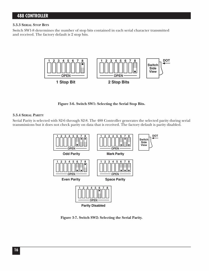
3.3.3 SERIAL STOP BITS
Switch SW1-8 determines the number of stop bits contained in each serial character transmitted and received. The factory default is 2 stop bits.
Figure 3-6. Switch SW1: Selecting the Serial Stop Bits.
3.3.4 SERIAL PARITY
Serial Parity is selected with S2-6 through S2-8. The 488 Controller generates the selected parity during serialtransmissions but it does not check parity on data that is received. The factory default is parity disabled.
Figure 3-7. Switch SW2: Selecting the Serial Parity.
SwitchSideView
DOT1 2 3 4 5 6 7 8
OPEN
Mark Parity
1 2 3 4 5 6 7 8
OPEN
Odd Parity
1 2 3 4 5 6 7 8
OPEN
Space Parity
1 2 3 4 5 6 7 8
OPEN
Even Parity
1 2 3 4 5 6 7 8
OPEN
Parity Disabled
SwitchSideView
DOT1 2 3 4 5 6 7 8
OPEN
2 Stop Bits
1 2 3 4 5 6 7 8
OPEN
1 Stop Bit
CHAPTER 3: Getting Started
17
3.3.5 SERIAL ECHO
Serial data sent to the 488 Controller will be echoed back to the serial host if SW2-5 is set to the openposition. The factory default is Echo Disabled.
Figure 3-8. Switch SW2: Enabling or Disabling Echo.
3.3.6 SERIAL HANDSHAKE
Switch SW1-5 is used to select hardware [RTS/CTS] or software [X-ON/X-OFF] serial handshake control.
With X-ON/X-OFF, the 488 Controller issues an X-OFF character [ASCII value of &H13] when its buffermemory is near full. When the X-OFF character is sent, there are still more than 1000 character locationsremaining to protect against buffer overrun. When it is able to accept more information, the 488 Controllerissues an X-ON character [ASCII value of &H11]. The 488 Controller also accepts X-ON/ X-OFF ontransmit from the serial host it is communicating with. RTS/CTS serial control becomes inactive when X-ON/X-OFF is enabled. The RTS output is, however, set to an active high state. The CTS input is not used for this handshake and may be left floating (unconnected).
With RTS/CTS, the 488 Controller un-asserts RTS (sets RTS low) when its buffer memory is near full. WhenRTS is un-asserted, there are still more than 1000 character locations remaining to protect against bufferoverrun. When it is able to accept more information, the 488 Controller asserts RTS (sets RTS high). The488 Controller will not transmit data to the serial host if it detects the CTS input un-asserted (low) whenconfigured for this hardware handshake.
The factory-default serial control is hardware, RTS/CTS.
Figure 3-9. Switch SW1: Selecting the Serial Handshake.
SwitchSideView
DOT1 2 3 4 5 6 7 8
OPEN
RTS/CTS
1 2 3 4 5 6 7 8
OPEN
X-ON/X-OFF
1 2 3 4 5 6 7 8
OPEN
Echo Disabled
1 2 3 4 5 6 7 8
OPEN
Echo Enabled
SwitchSideView
DOT
488 CONTROLLER
18
3.4 Selecting Terminator SubstitutionIn the Controller and Peripheral Modes, the 488 Controller is not sensitive as to whether CR or LF is used as a serial input terminator to a command. In general, it requires only one of either to cause commandexecution. The IEEE input terminator is fixed to LF. The switches that allow terminator selection, shown inthe following diagrams, set only the serial output and IEEE output terminators for these modes of operation.
In the transparent Pass-Thru modes, the 488 Controller can be configured to provide RS-232-to-IEEE 488and IEEE-488-to-RS-232 terminator substitution. This is useful when interfacing an RS-232 device which onlyissues carriage return [CR] as an output terminator to an IEEE controller which expects a carriage returnfollowed by a line feed [CR-LF].
In the above case, the serial terminator should be selected for CR Only while the IEEE terminator is set toCR-LF. When a serial CR character is received, it is discarded, and an IEEE CR-LF is substituted for it. In theIEEE-to-RS-232 direction, the IEEE CR is unconditionally discarded. Upon receipt of the IEEE LF, a serialCR is substituted.
The 488 Controller can be made totally data transparent in the Pass-Thru modes by setting both the serialand IEEE terminators to be CR Only or LF Only.
3.4.1 SERIAL TERMINATOR
SW2-3 and SW2-4 select the serial terminators for the serial input (Pass-Thru Modes Only) and output. The factory default is CR-LF.
Figure 3-10. Switch SW2: Selecting the Serial Terminator.
SwitchSideView
DOT
CR Only
1 2 3 4 5 6 7 8
OPEN
LF-CR
1 2 3 4 5 6 7 8
OPEN
1 2 3 4 5 6 7 8
OPEN
LF Only
1 2 3 4 5 6 7 8
OPEN
CR-LF
CHAPTER 3: Getting Started
19
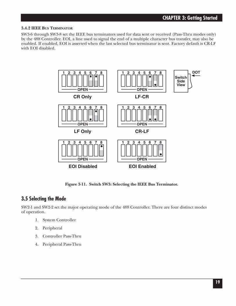
3.4.2 IEEE BUS TERMINATOR
SW3-6 through SW3-8 set the IEEE bus terminators used for data sent or received (Pass-Thru modes only) by the 488 Controller. EOI, a line used to signal the end of a multiple character bus transfer, may also beenabled. If enabled, EOI is asserted when the last selected bus terminator is sent. Factory default is CR-LFwith EOI disabled.
Figure 3-11. Switch SW3: Selecting the IEEE Bus Terminator.
3.5 Selecting the ModeSW2-1 and SW2-2 set the major operating mode of the 488 Controller. There are four distinct modes of operation.
1. System Controller
2. Peripheral
3. Controller Pass-Thru
4. Peripheral Pass-Thru
SwitchSideView
DOT
1 2 3 4 5 6 7 8
OPEN
LF Only
1 2 3 4 5 6 7 8
OPEN
CR-LF
1 2 3 4 5 6 7 8
OPEN
CR Only
1 2 3 4 5 6 7 8
OPEN
LF-CR
1 2 3 4 5 6 7 8
OPEN
EOI Disabled
1 2 3 4 5 6 7 8
OPEN
EOI Enabled
488 CONTROLLER
20
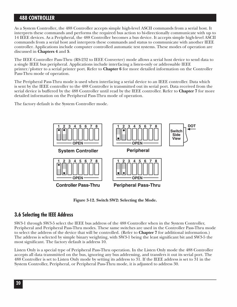
As a System Controller, the 488 Controller accepts simple high-level ASCII commands from a serial host. Itinterprets these commands and performs the required bus action to bi-directionally communicate with up to14 IEEE devices. As a Peripheral, the 488 Controller becomes a bus device. It accepts simple high-level ASCIIcommands from a serial host and interprets these commands and status to communicate with another IEEEcontroller. Applications include computer controlled automatic test systems. These modes of operation arediscussed in Chapters 4 and 5.
The IEEE Controller Pass-Thru (RS-232 to IEEE Converter) mode allows a serial host device to send data toa single IEEE bus peripheral. Applications include interfacing a listen-only or addressable IEEEprinter/plotter to a serial printer port. Refer to Chapter 6 for more detailed information on the ControllerPass-Thru mode of operation.
The Peripheral Pass-Thru mode is used when interfacing a serial device to an IEEE controller. Data which is sent by the IEEE controller to the 488 Controller is transmitted out its serial port. Data received from theserial device is buffered by the 488 Controller until read by the IEEE controller. Refer to Chapter 7 for moredetailed information on the Peripheral Pass-Thru mode of operation.
The factory default is the System Controller mode.
Figure 3-12. Switch SW2: Selecting the Mode.
3.6 Selecting the IEEE AddressSW3-1 through SW3-5 select the IEEE bus address of the 488 Controller when in the System Controller,Peripheral and Peripheral Pass-Thru modes. These same switches are used in the Controller Pass-Thru modeto select the address of the device that will be controlled. (Refer to Chapter 7 for additional information.)The address is selected by simple binary weighting, with SW3-1 being the least significant bit and SW3-5 themost significant. The factory default is address 10.
Listen Only is a special type of Peripheral Pass-Thru operation. In the Listen Only mode the 488 Controlleraccepts all data transmitted on the bus, ignoring any bus addressing, and transfers it out its serial port. The488 Controller is set to Listen Only mode by setting its address to 31. If the IEEE address is set to 31 in theSystem Controller, Peripheral, or Peripheral Pass-Thru mode, it is adjusted to address 30.
SwitchSideView
DOT
1 2 3 4 5 6 7 8
OPEN
Controller Pass-Thru
1 2 3 4 5 6 7 8
OPEN
Peripheral Pass-Thru
1 2 3 4 5 6 7 8
OPEN
PeripheralSystem Controller
1 2 3 4 5 6 7 8
OPEN
CHAPTER 3: Getting Started
21
Figure 3-13. Switch SW3: Selecting the IEEE Address.
3.7 Feature SelectionsThe functions of the remaining switches are dependent on the mode selected. A brief description of each of these features follows. You should refer to the listed sections for additional information.
3.7.1 CONTROLLER PASS-THRU FEATURES
In the IEEE Controller (RS-232-to-IEEE-488 converter) mode, SW1-7 is used to determine whether theinterface should, after sending the IEEE bus terminators, address the attached bus device to talk. Thefactory default is Talk-back On Terminator enabled.
Refer to Chapter 6 for complete details on these features.
Figure 3-14. Switch SW1: Enabling or Disabling “Talk Back on Terminator” in Controller Mode.
SwitchSideView
DOT1 2 3 4 5 6 7 8
OPEN
Talk-Back onTerminator Disabled
1 2 3 4 5 6 7 8
OPEN
Talk-Back onTerminator Enabled
SwitchSideView
DOT1 2 3 4 5 6 7 8
OPEN
0
1
0 x 161 x 80 x 41 x 20 x 1
=0=8=0=2
+ -0
IEEE Address = 10
488 CONTROLLER
22
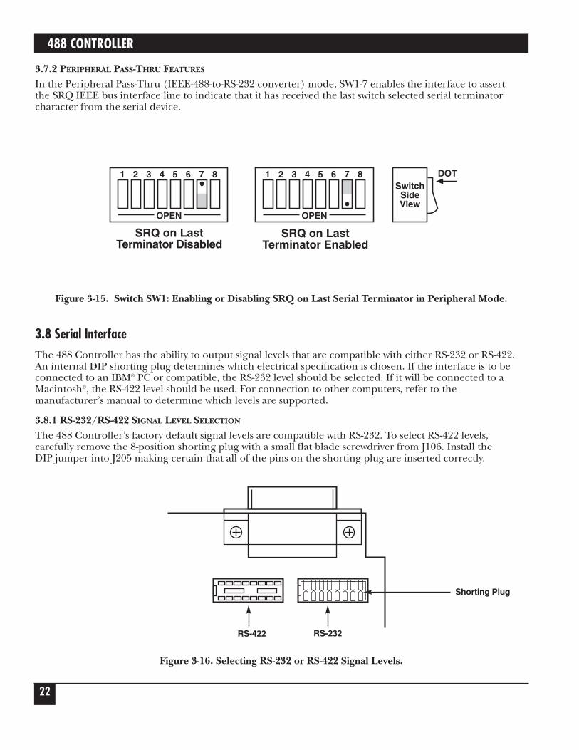
3.7.2 PERIPHERAL PASS-THRU FEATURES
In the Peripheral Pass-Thru (IEEE-488-to-RS-232 converter) mode, SW1-7 enables the interface to assert the SRQ IEEE bus interface line to indicate that it has received the last switch selected serial terminatorcharacter from the serial device.
Figure 3-15. Switch SW1: Enabling or Disabling SRQ on Last Serial Terminator in Peripheral Mode.
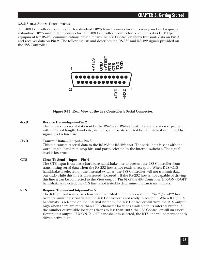
3.8 Serial InterfaceThe 488 Controller has the ability to output signal levels that are compatible with either RS-232 or RS-422.An internal DIP shorting plug determines which electrical specification is chosen. If the interface is to beconnected to an IBM® PC or compatible, the RS-232 level should be selected. If it will be connected to aMacintosh®, the RS-422 level should be used. For connection to other computers, refer to themanufacturer’s manual to determine which levels are supported.
3.8.1 RS-232/RS-422 SIGNAL LEVEL SELECTION
The 488 Controller’s factory default signal levels are compatible with RS-232. To select RS-422 levels,carefully remove the 8-position shorting plug with a small flat blade screwdriver from J106. Install the DIP jumper into J205 making certain that all of the pins on the shorting plug are inserted correctly.
Figure 3-16. Selecting RS-232 or RS-422 Signal Levels.
SwitchSideView
DOT1 2 3 4 5 6 7 8
OPEN
SRQ on LastTerminator Disabled
1 2 3 4 5 6 7 8
OPEN
SRQ on LastTerminator Enabled
Shorting Plug
RS-232RS-422
CHAPTER 3: Getting Started
23
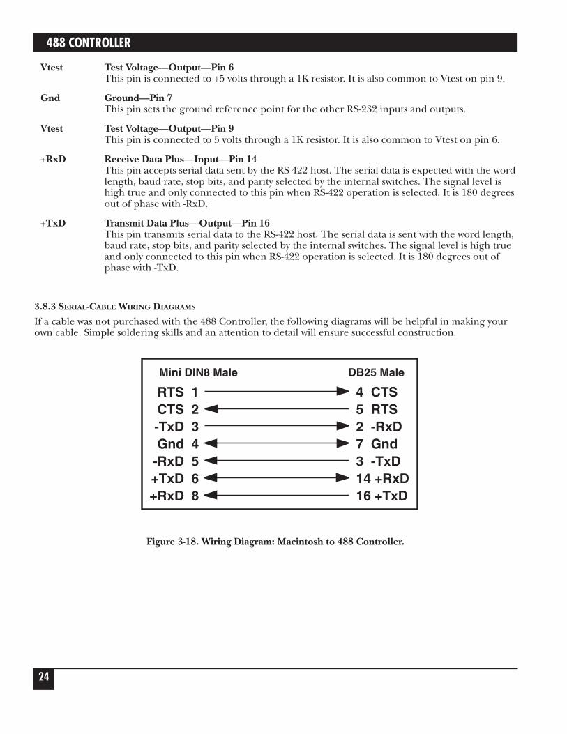
3.8.2 SERIAL SIGNAL DESCRIPTIONS
The 488 Controller is equipped with a standard DB25 female connector on its rear panel and requires a standard DB25 male mating connector. The 488 Controller’s connector is configured as DCE typeequipment for RS-232 communications, which means the 488 Controller always transmits data on Pin 3 and receives data on Pin 2. The following lists and describes the RS-232 and RS-422 signals provided on the 488 Controller.
Figure 3-17. Rear View of the 488 Controller’s Serial Connector.
-RxD Receive Data—Input—Pin 2This pin accepts serial data sent by the RS-232 or RS-422 host. The serial data is expectedwith the word length, baud rate, stop bits, and parity selected by the internal switches. Thesignal level is low true.
-TxD Transmit Data—Output—Pin 3This pin transmits serial data to the RS-232 or RS-422 host. The serial data is sent with theword length, baud rate, stop bits, and parity selected by the internal switches. The signallevel is low true.
CTS Clear To Send—Input—Pin 4The CTS input is used as a hardware-handshake line to prevent the 488 Controller fromtransmitting serial data when the RS-232 host is not ready to accept it. When RTS/CTShandshake is selected on the internal switches, the 488 Controller will not transmit data out -TxD while this line is un-asserted (lowered). If the RS-232 host is not capable of drivingthis line it can be connected to the Vtest output (Pin 6) of the 488 Controller. If X-ON/X-OFFhandshake is selected, the CTS line is not tested to determine if it can transmit data.
RTS Request To Send—Output—Pin 5The RTS output is used as a hardware handshake line to prevent the RS-232/RS-422 hostfrom transmitting serial data if the 488 Controller is not ready to accept it. When RTS/CTShandshake is selected on the internal switches, the 488 Controller will drive the RTS outputhigh when there are more than 1000 character locations available in its internal buffer. If the number of available locations drops to less than 1000, the 488 Controller will un-assert(lower) this output. If X-ON/X-OFF handshake is selected, the RTS line will be permanentlydriven active high.
13 1
25 14
-RX
D-T
XD
CT
SR
TS
+VT
ES
TG
ND
+VT
ES
T
+RX
D
+TX
D
488 CONTROLLER
24
Vtest Test Voltage—Output—Pin 6This pin is connected to +5 volts through a 1K resistor. It is also common to Vtest on pin 9.
Gnd Ground—Pin 7This pin sets the ground reference point for the other RS-232 inputs and outputs.
Vtest Test Voltage—Output—Pin 9This pin is connected to 5 volts through a 1K resistor. It is also common to Vtest on pin 6.
+RxD Receive Data Plus—Input—Pin 14This pin accepts serial data sent by the RS-422 host. The serial data is expected with the wordlength, baud rate, stop bits, and parity selected by the internal switches. The signal level ishigh true and only connected to this pin when RS-422 operation is selected. It is 180 degreesout of phase with -RxD.
+TxD Transmit Data Plus—Output—Pin 16This pin transmits serial data to the RS-422 host. The serial data is sent with the word length,baud rate, stop bits, and parity selected by the internal switches. The signal level is high trueand only connected to this pin when RS-422 operation is selected. It is 180 degrees out ofphase with -TxD.
3.8.3 SERIAL-CABLE WIRING DIAGRAMS
If a cable was not purchased with the 488 Controller, the following diagrams will be helpful in making yourown cable. Simple soldering skills and an attention to detail will ensure successful construction.
Figure 3-18. Wiring Diagram: Macintosh to 488 Controller.
Mini DIN8 Male DB25 Male
RTS 1CTS 2-TxD 3Gnd 4
-RxD 5+TxD 6+RxD 8
4 CTS5 RTS2 -RxD7 Gnd3 -TxD14 +RxD16 +TxD
CHAPTER 3: Getting Started
25
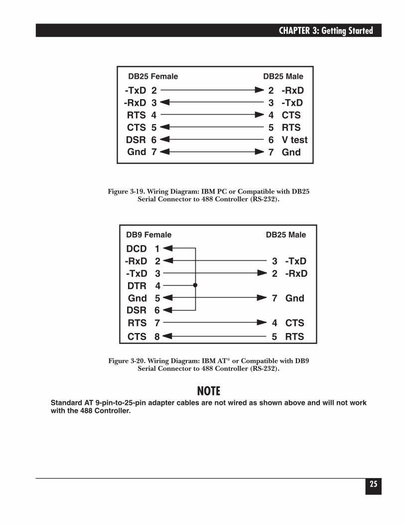
Figure 3-19. Wiring Diagram: IBM PC or Compatible with DB25 Serial Connector to 488 Controller (RS-232).
Figure 3-20. Wiring Diagram: IBM AT® or Compatible with DB9 Serial Connector to 488 Controller (RS-232).
NOTEStandard AT 9-pin-to-25-pin adapter cables are not wired as shown above and will not workwith the 488 Controller.
3.9 General OperationRefer to the following sections for specific operational modes. This section gives a general test of function-ality. After setting the power-on defaults and reassembling the 488 Controller, plug the power-supplyconnector into the rear jack on the interface.
CAUTIONNever plug the power supply into the 488 Controller while it is connected to AC line power.If you do, you could damage the 488 Controller.
WARNINGThe power supply provided with the interface is intended for indoor use only. Using itoutdoors could result in equipment failure, personal injury, or death.
After plugging the power supply connector into the 488 Controller, plug the power supply into AC linepower. Turn the rear-panel power switch ON (the “1” position). All the front-panel indicators should lightmomentarily while the 488 Controller performs an internal ROM and RAM self-check. At the end of thisself-check, all indicators except POWER should turn off.
If there is an error in the ROM checksum, all of the LEDs will remain on. Flashing LEDs indicate a RAMfailure. Should such an error occur, turn the rear panel switch to the OFF [0] position and retry the aboveprocedure.
If the front-panel indicators do not flash and the POWER indicator does not remain lit, there may not beany power supplied to the interface. In this event, check the AC line and the rear-panel connection of thepower supply.
If proper operation is obtained, connect an interface cable to the rear of the 488 Controller (25-Pin Sub-D).Connect the other end to the host’s serial port. Except for connecting IEEE bus instruments, the 488Controller is installed and ready to use.
WARNINGThe 488 Controller makes its earth ground connection through the serial interface cable. Itshould only be connected to IEEE bus devices after being first connected to the host.Failure to do so may allow the 488 Controller to float to a bus device test voltage. Thiscould result in damage to the 488 Controller, personal injury, or death.
CHAPTER 3: Getting Started
27
3.10 Is Anyone Out There?Before connecting any IEEE bus devices to the 488 Controller, try this simple operational check. The 488Controller must be configured for either System Controller or Peripheral mode operation. This test will not work in either of the Pass-Thru modes.
Running BASIC on the host, or any programming language which supports the serial ports, type thefollowing (or its equivalent).
OPEN "COM1:9600, N, 8, 2, cd, ds" AS 1 [Return]
PRINT #1,"HELLO" [Return]
LINE INPUT #1,A$ [Return]
PRINT A$ [Return]
The 488 Controller will respond with (and the host will display):
488 Controller Revision N.N Copyright (C) 1988
where N.N is the release and revision number of the firmware.
If you obtain the response above, then your 488 Controller is alive and well and ready to connect your hostto the powerful IEEE-488 General Purpose Interface Bus. If you did not receive the message above, checkfor proper connection and fit of the interface cable. If, after reviewing the 488 Controller for properinstallation, call your supplier.
488 CONTROLLER
28
4.1 IntroductionThere are four types of IEEE bus devices: Active Controllers, Peripherals, Talk-Only devices, and Listen-Always devices. Talk-Only and Listen-Always devices are usually used together, in simple systems, such as a Talk-Only digitizer sending results to a Listen-Always plotter. In these simple systems, no controller isneeded, because the talker assumes that it is the only talker on the bus, and the listener(s) assume that they are all supposed to receive all the data sent over the bus. This is a simple and effective method oftransferring data from one device to another, but is not adequate for more complex systems where, forexample, one computer is controlling many different bus devices.
In more complex systems, the Active Controller sends commands to the various bus Peripherals telling themwhat to do. Commands such as Unlisten, Listen Address Group, Untalk, and Talk Address Group are sent bythe controller to specify which device is to send data, and which devices are to receive it. For more detailsabout the IEEE bus protocols see Chapter 8.
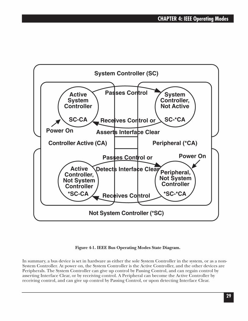
When an IEEE bus system is first turned on, some device must be the Active Controller. This device is theSystem Controller and always keeps some control of the bus. In particular, the System Controller controlsthe Interface Clear (IFC) and Remote Enable (REN) bus management lines. By asserting Interface Clear,the System Controller forces all the other bus devices to stop their bus operations, and regains control as the Active Controller.
4.2 Operating Mode TransitionsThe System Controller is initially the Active Controller. It can, if desired, pass control to another device and thereby make that device the Active Controller. Note that the System Controller remains the SystemController, even when it is not the Active Controller. Of course, the device to which control is passed mustbe capable of taking on the role of Active Controller. It would make no sense to try to pass control to aprinter. Control should only be passed to other computers that are capable, and ready, to become the ActiveController. Further, note that there must be exactly one System Controller on the IEEE bus. All otherpotential controllers must be configured as Peripherals when they power up.
The state diagram on the next page shows the relationships between the various operating modes. The tophalf of the state diagram shows the two operating states of a System Controller. At power-on, it is the activecontroller. It directs the bus transfers by sending the bus commands mentioned previously. It also hascontrol of the Interface Clear and Remote Enable bus lines. The System Controller can pulse InterfaceClear to reset all of the other bus devices.
As shown in the diagram, the System Controller can pass control to some other bus device and therebybecome a Peripheral to the new Active Controller. If the System Controller receives control from the newActive Controller, then it will once again become the Active Controller. The System Controller can also force the Active Controller to relinquish control by asserting the Interface Clear signal.
The bottom half of the state diagram shows the two operating states of a Not System Controller device. Atpower on, it is a Peripheral to the System Controller, which is the Active Controller. If it receives controlfrom the Active Controller, it becomes the new Active Controller. Even though it is the Active Controller, it is still not the System Controller. The System Controller can force the Active Controller to give up control by asserting Interface Clear. The Active Controller can also give up control by passing control to anotherdevice, which may or may not be the System Controller.
4. IEEE Operating Modes
CHAPTER 4: IEEE Operating Modes
29
Figure 4-1. IEEE Bus Operating Modes State Diagram.
In summary, a bus device is set in hardware as either the sole System Controller in the system, or as a non-System Controller. At power on, the System Controller is the Active Controller, and the other devices arePeripherals. The System Controller can give up control by Passing Control, and can regain control byasserting Interface Clear, or by receiving control. A Peripheral can become the Active Controller byreceiving control, and can give up control by Passing Control, or upon detecting Interface Clear.
ActiveSystem
Controller
SC-CA
ActiveController,Not SystemController*SC-CA
SystemController,Not Active
SC-*CA
Peripheral,Not SystemController
*SC-*CA
Power On
Power On
Controller Active (CA) Peripheral (*CA)
Not System Controller (*SC)
Passes Control
Receives Control or
Asserts Interface Clear
Receives Control
Passes Control or
Detects Interface Clear
System Controller (SC)
488 CONTROLLER
30
4.3 System Controller ModeThe most common 488 Controller configuration is as the System Controller, controlling several IEEE-businstruments. In this mode, the 488 Controller can perform all of the various IEEE-bus protocols necessary tocontrol and communicate with any IEEE-488-bus devices. As the System Controller in the Active Controllermode, the 488 Controller can use all of the commands available for the Active Controller state, plus controlthe Interface Clear and Remote Enable lines. The allowed bus commands and their actions are as follows:
ABORT Pulse Interface Clear.
LOCAL Unassert Remote Enable, or send Go To Local to selected devices.
REMOTE Assert Remote Enable, optionally setting devices to Remote.
LOCAL LOCKOUT Prevent local (front-panel) control of bus devices.
CLEAR Clear all or selected devices.TRIGGER Trigger selected devices.
ENTER Receive data from a bus device. OUTPUT Send data to bus devices.
PASS CONTROL Give up control to another device which becomes the ActiveController.
SPOLL Serial Poll a bus device, or check the Service Request state.
PPOLL Parallel Poll the bus. PPOLL CONFIG Configure Parallel Poll responses. PPOLL DISABLE Disable the Parallel Poll response of selected bus devices. PPOLL UNCONFIG Disable the Parallel Poll response of all bus devices.
SEND Send low-level bus sequences. RESUME Unassert Attention. Used to allow Peripheral-to-Peripheral transfers.
CHAPTER 4: IEEE Operating Modes
31
4.4 System Controller, Not Active Controller ModeAfter Passing Control to another device, the System Controller is no longer the Active Controller. It acts as a Peripheral to the new Active Controller, and the allowed bus commands and their actions are modifiedaccordingly. However, it still maintains control of the Interface Clear and Remote Enable lines. The availablebus commands and their actions are:
ABORT Pulse Interface Clear.
LOCAL Unassert Remote Enable. REMOTE Assert Remote Enable.
ENTER Receive data from a bus device as directed by the Active Controller. OUTPUT Send data to bus devices as directed by the Active Controller.
REQUEST Set own Serial Poll request (including Service Request) status. SPOLL Get own Serial Poll request status.
As a bus Peripheral, the 488 Controller must respond to the commands issued by the Active Controller. Thecontroller can, for example, address the 488 Controller to listen in preparation for sending data. There aretwo ways of detecting our being addressed to listen: through the STATUS command, or by detecting anevent with the ARM or ON DOMACRO commands.
The STATUS 1 command can be used to watch for commands from the Active Controller. The OperatingMode, which is a “P” while the 488 Controller is a Peripheral, will change to a “C” if the Active ControllerPasses Control to the 488 Controller. The Addressed State will go from Idle (“I”) to Listener (“L”) or Talker(“T”) if the 488 Controller is addressed to listen or to talk, and will go back to Idle (“I”) when the ActiveController issues Unlisten (UNL), Untalk (UNT), or specifies another talker (TAG). The Triggered (“T1”)and Cleared (“C1”) indicators will be set when the 488 Controller is triggered or cleared, and reset whenSTATUS 1 is read. The Address Change indicator will be set (“G1”) when the address state changes. Theseindicators allow the program to sense the commands issued to the 488 Controller by the Active Controller.The following BASIC program fragment illustrates the use of the Address Change and Addressed Stateindicators to communicate with the Active Controller:
488 CONTROLLER
32
First we check STATUS until it indicates that there has been an address change:
200 PRINT#1,"STATUS1"
210 INPUT#2 ST$
220 'Has there been no Address Change?
230 IF MID$(ST$,7,1)="0" THEN 200
240 'Are will still in the idle state?
250 STATE$=MID$(ST$,9,1)
260 IF STATE$="I" THEN 200
270 'Are we addressed to listen?
280 IF STATE$="L" THEN 400
290 'Are we addressed to talk?
300 IF STATE$="T" THEN 500
310 PRINT "BAD ADDRESSED STATE VALUE: ";ST$: STOP
If we are addressed to listen then we ENTER a line from the controller and print it out.
400 'Listen state
410 PRINT#1,"ENTER"
420 LINE INPUT#1,A$
430 PRINT A$
440 GOTO 200
If we are addressed to talk then we INPUT a line from the keyboard and OUTPUT it to the controller.
500 'Talk state
510 LINE INPUT A$
520 PRINT#1,"OUTPUT;";A$
530 GOTO 200
CHAPTER 4: IEEE Operating Modes
33
It is also possible to detect these conditions with the ARM or ON DOMACRO commands and handle themin an exception as described in Chapter 5. The various arm conditions and their meanings are as follows:
SRQ The internal Service Request state is set. See the SPOLL command inChapter 5.
PERIPHERAL The 488 Controller is in the Peripheral (*CA) operating mode.CONTROLLER The 488 Controller is the Active Controller (CA).
TRIGGER The 488 Controller, as a Peripheral, has received a Trigger bus command.CLEAR The 488 Controller, as a Peripheral, has received a Clear bus command.
TALK The 488 Controller is in the Talk state and can OUTPUT to the bus.LISTEN The 488 Controller is in the Listen state and can ENTER from the bus.IDLE The 488 Controller is in neither the Talk nor Listen state.
CHANGE An Address Change has occurred, i.e. a change between Peripheral andController, or among Talk, Listen, and Idle has occurred.
ERROR An error, either command or bus, has been detected by the 488 Controller.
4.5 Not System Controller ModeIf the 488 Controller is configured as not the System Controller then, at power on, it will be a busPeripheral. It might use a program like the one described previously to communicate with the ActiveController. The bus commands available to the 488 Controller when it is not the System Controller and not the Active Controller (*SC*CA) are:
ENTER Receive data from a bus device as directed by the Active Controller.OUTPUT Send data to bus devices as directed by the Active Controller
REQUEST Set own Serial Poll request (including Service Request) status. SPOLL Get own Serial Poll request status.
488 CONTROLLER
34
4.6 Active Controller, Not System Controller ModeIf the Active Controller passes control to the the 488 Controller, then the 488 Controller will become thenew Active Controller. This can be detected by the STATUS command or as an ARMed event. As an ActiveController, but not the System Controller, the following bus commands are available:
ABORT Assert Attention and send My Talk Address to stop any bus transfers.
LOCAL Send Go To Local to selected devices.
LOCAL LOCKOUT Prevent local (front-panel) control of bus devices.
CLEAR Clear all or selected devices. TRIGGER Trigger selected devices.
ENTER Receive data from a bus device. OUTPUT Send data to bus devices.
PASS CONTROL Give up control to another device, which becomes the Active Controller.
SPOLL Serial-Poll a bus device, or check the Service Request state. PPOLL Parallel-Poll the bus. PPOLL CONFIG Configure Parallel-Poll responses.PPOLL DISABLE Disable the Parallel-Poll response of selected bus devices. PPOLL UNCONFIG Disable the Parallel-Poll response of all bus devices.
SEND Send low-level bus sequences. RESUME Unassert Attention. Used to allow Peripheral-to-Peripheral transfers.
4.7 Controller Pass-Thru ModeThis mode is intended to provide bi-directional data-transparent conversion between an RS-232/RS-422 hostcomputer and an IEEE 488 peripheral, such as a printer or an HP®-IB plotter. The operation of this mode iscovered in Chapter 6 of this manual.
4.8 Peripheral Pass-Thru ModeThis mode is intended to provide bi-directional data transparent conversion between an IEEE 488 controllerand a serial device. This Peripheral Pass-Thru mode does not require the serial device to control data to it.There is no command line, so this mode requires no serial commands. This mode of operation is describedin Chapter 7 of this manual.
CHAPTER 5: Command Descriptions
35
5.1 IntroductionThis section contains a detailed description of each of the high-level commands available for the 488Controller. There are two types of commands: bus commands and system commands. Bus commandscommunicate with the IEEE 488 bus. System commands configure or request information from the 488 Controller.
Bus Commands:
ABORT PPOLL CONFIG
CLEAR PPOLL DISABLE
ENTER PPOLL UNCONFIG
LOCAL REMOTE
LOCAL LOCKOUT REQUEST
OUTPUT RESUME
PASS CONTROL SEND
PPOLL SPOLL
TRIGGER
System Commands:
ARM MACROENDM
COMMENT MASK
COUNT MEMORY
DELAY ON <event> DOMACRO
DISARM READ
DOMACRO RESET
ERASE STATUS
ERROR STERM
HELLO TERM
ID TIME OUT
TRACE
5. Command Descriptions
488 CONTROLLER
36
5.2 Command-Description FormatEach command description is divided into several areas:
5.2.1 SYNTAX
The syntax section of the command description describes the proper command syntax which must be sent tothe 488 Controller using the IBM BASIC PRINT# command, or its equivalent in other languages, to theCOM port. The following conventions are used in the syntax descriptions:
No command, along with its options, may be more than 127 characters long. The data part of the OUTPUTcommand is not constrained by this length. It is, however, limited to the available USER MEMORY. TheOUTPUT #count;data may be as long as necessary. Refer to the OUTPUT command for more informationon this.
Items in capital letters, such as ENTER or OUTPUT, must be entered exactly as stated, except thatabbreviations may be used with some commands to reduce serial transmission traffic.
Items in lower case, such as addr or count, represent parameters which must be substituted with anappropriate value.
Blank spaces in commands are generally ignored. Thus, LOCAL LOCK OUT is the same asLOCALLOCKOUT. Spaces are not ignored in four places: the data part of an OUTPUT command, withinquoted strings in a SEND command, after an apostrophe (') in a terminator specification (term), and afterthe semi-colon following the ID command.
The number sign (#) and the semicolon (;) must be present exactly as shown. A comma (,) represents anaddress separator. The slash (/) or period (.) may be used in its place as the address separator.
Optional semicolons ([;]) may be used, if desired.
Items enclosed in square brackets ([item]) are optional. Multiple items enclosed in square bracketsseparated by vertical lines ([item1|item2|item3]) are optional; any one or none may be chosen. No morethan one item may be selected.
Ellipses (...) within square brackets mean that the items in the brackets may be repeated as many times asdesired. For example [,addr] means that any number, to a maximum of 15, of address-separator/addresscombinations may be used.
Braces, or curly brackets ({item1|item2}), mean that exactly one of the enclosed items is required.
Combinations of brackets are possible. For example, {term[term] [EOI] |EOI} allows the choice of “term,”“term EOI,” “term term,” “term term EOI,” or just “EOI,” but does not allow the choice of “nothing.”
Numeric parameters (those that are given as numbers) are decimal unless preceded by &H, in which casethey are considered to be hexadecimal. Thus 100 is decimal 100, &H64 is hexadecimal 64 which equalsdecimal 100, &HFF is decimal 255, and 0FF is invalid because F is not a valid decimal digit. The onlyexception to this rule is that bus addresses, both primary and secondary, must be specified as two-digitdecimal numbers. Hexadecimal bus addresses are not allowed.
CHAPTER 5: Command Descriptions
37
Several of the commands require additional or optional parameters. These are further described with eachcommand, but discussion of the more common ones follows.
Bus Addressing
pri-addr A two-digit primary device address in the range of 00 to 30.
sec-addr An optional two-digit secondary device address in the range of 00 to 31.
addr An IEEE bus address. A numeric primary address optionally followed by a secondaryaddress. Thus addr is of the form...
{pri-addr [sec-addr]}
where pri-addr is a two-digit primary address in the range from 00 through 30 andsec-addr is a two-digit secondary address from 00 through 31. Numeric addressesmust be given as two-digit numbers: for example, 05 for address 5, and 1601 forprimary address 16, secondary address 1.
[,addr] An optional list of bus addresses, each one preceded by an address separator: either acomma (,), a slash (/) or a period (.).
No more than 15 bus addresses are allowed in any single command.
Character Count
#count The number of characters to be transferred. A pound sign (#) followed by an integerin the range of 1 to 65535 (216-1). May be specified in hexadecimal by preceding itwith &H. The hexadecimal range is &H1 to &HFFFF. A character count of zero isinvalid.
ASCII Characters
$char A single character whose ASCII value is the number char, a decimal number in therange of 0 to 255 or a hexadecimal number in the range of &H0 to &HFF. Forexample, $65 is the letter “A,” as is $&H41.
CR The carriage return character ($13, $&H0D).
LF The line feed character ($10, $&H0A).
'X Any printable character. The apostrophe is immediately followed, without anyintervening spaces, by a single character which is taken to be the character specified.
ASCII Character Strings
data An arbitrary string of characters. None of the special forms given above ($char, CR,LF, or 'X) are used. For example, CRLF as data is taken as the letters “C,” “R,” “L,”and “F,” not as carriage return and line feed.
'data' An arbitrary string of characters enclosed in apostrophes (') or quotes (").
488 CONTROLLER
38
Terminators
term Any single character, specified as CR, LF, 'X, or $char as described previously. Part of terminator sequence used to mark the end of lines of data and commands.
[term] An optional term character. term[term], means that one or two terminators may be specified.
EOI The IEEE bus End-Or-Identify signal. When asserted during the transfer of acharacter, EOI signals that that character is the last in the transfer. On input, EOI, if specified, causes the input to stop. On output, EOI causes the bus EOI signal to be asserted during transmission of the last character.
NONE The no-end-of-line-character indicator. When STERM NONE is specified, the 488Controller does not append any serial output terminator(s) to serially transmitteddata.
5.2.2 RESPONSE
The response section of the command description describes the response that the user’s program shouldread from the serial host’s COM port after sending the command. If a response is provided, it must be readto maintain proper program sequence.
5.2.3 MODE
This section of the command description specifies the operating modes in which the command is valid. The 488 Controller may be configured as the System Controller, in which case it will initially be the ActiveController, or as a Not System Controller, in which case it will initially be in the Peripheral state. The 488Controller configuration as System Controller or Not System Controller is fixed by a hardware switch settingand cannot be changed by software, but the 488 Controller can change between Active Controller andPeripheral as required (see Chapter 4).
The modes are referred to by their names and states, as given in the table below:
Description State
System Controller SCNot System Controller *SC
Active Controller CAPeripheral (Not Active Controller) *CA
Active System Controller SCCASystem Controller, Not Active Controller SC*CA
Not System Controller, Not Active Controller *SC*CANot System Controller, Active Controller *SCCA
CHAPTER 5: Command Descriptions
39
5.2.4 BUS STATES
This section describes the bus command and data transfers using IEEE bus mnemonics, abbreviated as follows:
DIO lines
8 7 6 5 4 3 2 1
ATN Attention
data Data String
DCL Device Clear x 0 0 1 0 1 0 0
GET Group Execute Trigger x 0 0 0 1 0 0 0
GTL Go To Local x 0 0 0 0 0 0 1
IFC Interface Clear
LAG Listen Address Group x 0 1 a d d r n
LLO Local Lock Out x 0 0 1 0 0 0 1
MLA My Listen Address x 0 1 a d d r n
MTA My Talk Address x 1 0 a d d r n
PPC Parallel Poll Configure x 0 0 0 0 1 0 1
PPD Parallel Poll Disable x 1 1 1 0 0 0 0
PPE Parallel Poll Enable x 1 1 0 S P3 P2 P1
PPU Parallel Poll Unconfigure x 0 0 1 0 1 0 1
REN Remote Enable
SDC Selected Device Clear x 0 0 0 0 1 0 0
SPD Serial Poll Disable x 0 0 1 1 0 0 1
SPE Serial Poll Enable x 0 0 1 1 0 0 0
SRQ Service Request
TAG Talker Address Group x 1 0 a d d r n
TCT Take Control x 0 0 0 1 0 0 1
UNL Unlisten x 0 1 1 1 1 1 1
UNT Untalk x 1 0 1 1 1 1 1
(x = “don’t care”)
If a command is preceded by an asterisk, then that command is unasserted. For example, *REN states thatthe remote enable line is unasserted. Conversely, REN without the asterisk states that the line becomesasserted.
488 CONTROLLER
40
5.3 Memory UseMemory in the 488 Controller is dynamically allocated for the serial input, serial output and Macro buffers.This allows for the most efficient partitioning of memory for any given application. This memory is kept inthe user “heap” (a vernacular for heap of memory) until required by the system.
At power on, each serial buffer is allocated a 127-byte minibuffer or queue. When the serial input (oroutput) requires more buffer space, additional queues are allocated. When a queue is empty, it is releasedfrom the input buffers so that it may be re-allocated when, and where, required. Macro queues are notallocated unless a macro is defined.
There are approximately 240 available queues for a total of 29,000 bytes of buffer (character) space. Queuesare continually allocated and released as required. Of the 240 available queues, 230 are issued withoutregard to controlling the receipt of additional serial input data.
When the serial input buffer requests one of the last 10 queues (1270 character locations left), it signals the serial host that it should stop sending data. This is accomplished by either unasserting RTS or issuing “X-OFF,” depending on which serial handshake control has been switch selected. When more than 10queues become available, it asserts RTS or issues “X-ON.”
5.4. The CommandsThe commands provided in the 488 Controller, in alphabetical order, are described on the following pages.
@ Command
The system command @, followed by a CR and/or LF, is used to unlock the 488 Controller from aninappropriate command. An example of such a command would be requesting data from a nonexistentdevice with timeouts disabled.
When the @ command is received, the serial handshake line (RTS) is un-asserted. It is asserted when the 488 Controller is capable of buffering commands. If X-ON/X-OFF handshake is selected, the softwarehandshake state is not modified.
Issuing the @ command clears the serial input (pending commands) and output (pending data) buffers. It also is equivalent to issuing the following commands
DISARM
ERASE
ERROR OFF
ID;@
MASK OFF
REQUEST 0 (with *SRQ)
TIME OUT 0
TRACE OFF
CHAPTER 5: Command Descriptions
41
The @ character, referred to as the “ID” character, can be changed or disabled by using the ID command. If it is anticipated that the ID character may be part of the data within an OUTPUT or SEND command, it should be disabled.
SYNTAX @
RESPONSE None
MODE Any
BUS STATES None
EXAMPLE PRINT #1,"@"
@@ Command
Sending the system command @@ causes the 488 Controller to return to power-on conditions. All databuffers are cleared, and any software programmable terminators are returned to the power-on conditions.
This is the only command which does not require a serial terminator to execute. Reset is executed uponreceipt of the second @.
When the @@ command is received, the serial handshake line (RTS) is un-asserted. It is asserted when the488 Controller is capable of buffering commands. If XON/XOFF handshake is selected, the softwarehandshake state is reset.
The @ character, referred to as the “ID” character, can be changed or disabled by using the ID command. If it is anticipated that the ID character may be part of the data within an OUTPUT or SEND command, it should be disabled.
SYNTAX @@
RESPONSE None
MODE Any
BUS STATES: IFC,*IFC (SC)
EXAMPLE: PRINT #1,"@@"
ABORT Command
As the System Controller (SC), whether the 488 Controller is the Active Controller or not, the ABORTcommand causes the Interface Clear (IFC) bus management line to be asserted for at least 500 micros-econds. By asserting IFC, the 488 Controller regains control of the bus even if one of the devices has lockedit up during a data transfer. Asserting IFC also makes the 488 Controller the Active Controller. If a Non-System Controller was the Active Controller, it will be forced to relinquish control to the 488 Controller.ABORT forces all IEEE bus device interfaces into a quiescent idle state.
488 CONTROLLER
42
If the 488 Controller is a Non-System-Controller in the Active Controller state (*SCCA), it asserts attention(ATN), which halts any bus transactions, and sends its talk address to “untalk” any other talkers on the bus.It does not (and cannot) assert IFC if in the *SC state.
SYNTAX ABORT or AB
RESPONSE None
MODE SC or *SCCA
BUS STATES IFC, *IFC (SC)ATNMTA (*SCCA)
EXAMPLES PRINT#1,"ABORT"PRINT#1,"AB" Using abbreviated form
ARM Command
The ARM command allows the 488 Controller to automatically send event messages to the serial host whenone or more of the specified events occur. The event messages that are returned are the same non-abbreviated strings as those used to program the events.
There are two types of events, level sensitive and edge sensitive. Level-sensitive events, such as SRQ, will bereported every time they are ARMed while the event condition persists. Usually, some action must be taken(for example, SPOLL) to clear the condition before re-issuing the ARM. Edge-sensitive events, such asTRIGGER, are cleared when reported.
Regardless of the event sensitivity, the ARM command must be resent after the event message is reported tore-activate the ARMed condition. The optional events include
SRQ The event message “SRQ” is returned to the serial host when the state of the ServiceRequest Bus Line is detected in the asserted state. This event is level sensitive. If thecondition exists at the time the ARM SRQ command is issued, the 488 Controller willreturn the event message immediately. If the ARM command is issued without anyspecified events, the SRQ event is assumed. This provides upward compatibility with the 488 Controller in previous 488 Controller systems.
PERIPHERAL The event message “PERIPHERAL” is returned to the serial host when the 488Controller is forced from the Controller Active State (*SC-CA) to the Peripheral State(*SC-*CA) by receipt of IFC from the System Controller. This can be useful indetecting receipt of IFC when in the *SC-CA state. This event is edge-sensitive.
CONTROLLER The event message “CONTROLLER” is returned to the serial host when the 488Controller receives control of the bus and transitions from the Peripheral State (*SC-*CA) to the Controller Active State (*SC-CA) . This occurs when the Take Controlinterface message is received by the 488 Controller. This event is edge-sensitive.
TRIGGER The event message “TRIGGER” is returned to the serial host when the 488 Controller,as a Peripheral (*CA), receives a Group Execute Trigger (GET) command from theActive Controller. This event is edge-sensitive. When the event message is sent, theinternal status, as read by the STATUS 1 command, is cleared.
CHAPTER 5: Command Descriptions
43
CLEAR The event message “CLEAR” is returned to the serial host when the 488 Controller,as a Peripheral (*CA), receives a Device Clear (DCL) or a Selected Device Clear (SDC)command from the Active Controller. This event is edge-sensitive. When the eventmessage is sent, the internal status, as read by the STATUS 1 command, is cleared.
TALK The event message “TALK” is returned to the serial host when the 488 Controller, as a Peripheral (*CA), detects its My Talk Address (MTA) command from the ActiveController. It indicates that the controller has requested information from the 488 Controller. This event is edge-sensitive.
LISTEN The event message “LISTEN” is returned to the serial host when the 488 Controller, as a Peripheral (*CA), detects its My Listen Address (MLA) command from the ActiveController. It indicates that the controller has information it wants to send to the 488Controller. This event is edge-sensitive.
IDLE The event message “IDLE” is returned to the serial host when the 488 Controller, as aPeripheral (*CA), transitions from a Talker or Listener state to an idle state (neithertalker or listener). It indicates that the controller has unaddressed the 488 Controllerwith either an UNT or UNL command. This event is edge-sensitive. When the eventmessage is sent, the internal address-change status, as read by the STATUS 1 command,is cleared. This event is tested before the CHANGE event and will clear the internalCHANGE status only when the addressed-to-unaddressed transition occurs.
CHANGE The event message “CHANGE” is returned to the serial host when the 488 Controller,as a Peripheral (*CA), detects an addressed state change. This occurs on transitionsfrom a Talker or Listener state to an idle state (neither talker or listener), or from aidle state to a talker or listener state. This event is edge-sensitive. When the eventmessage is sent, the internal status, as read by the STATUS 1 command, is cleared. This event is tested after the IDLE event. If IDLE is ARMed, the CHANGE event willonly be reported when an unaddressed-to-addressed transition occurs.
ERROR The event message “ERROR” is returned to the serial host when the 488 Controllerdetects an error condition. The error condition may be an unrecognized commandfrom the serial host, an invalid parameter, or a bus error. Refer to Appendix B fora listing of the error conditions which can be detected and reported by the 488Controller. This event is level-sensitive. When the event message is sent, the errorstatus, as read by any of the STATUS commands, must be read before ARMing thisevent again.
488 CONTROLLER
44
Once a condition is ARMed, it remains ARMed until it is DISARMed, the event specified has occurred, orthe 488 Controller is reset.
The ARM and ON <event> DOMACRO commands are mutually exclusive. The last command issued takesprecedence.
SYNTAX ARM [;] [event[event]] or AR [;] [event[event]]
where event may include
Event Abbreviated Form
SRQ SRQ
PERIPHERAL PE
CONTROLLER CO
TRIGGER TR
CLEAR CL
TALK T
LISTEN L
IDLE I
CHANGE CH
ERROR ER
If no event is specified, ARM SRQ is assumed for upward compatibility with the 488 Controller.
RESPONSE Event string sent when event occurs
MODE any
BUS STATES None
EXAMPLE:
10 PRINT#1,"ARM TALK" Enable Talk Condition
20 INPUT#1,A$ Input “TALK” Status Message
30 PRINT#1,"OUTPUT;This is a test"
40 GOTO 10 Output data and try again
CHAPTER 5: Command Descriptions
45
CLEAR Command
The CLEAR command causes the Device Clear (DCL) bus command to be issued by the 488 Controller. Ifthe optional addresses are included, the Selected Device Clear (SDC) command is issued to all specifieddevices. IEEE 488 bus devices which receive a Device Clear or Selected Device Clear command normallyreset to their power-on state.
SYNTAX CLEAR [addr[,addr]]
or
CL [addr[,addr]]
addr is a device address (primary with optional secondary)., is the address separator—either a comma, a slash [/], or a period [.].
RESPONSE None
MODE CA
BUS STATES ATNDCL (all devices)ATNUNL,MTA,LAG,SDC (selected devices)
EXAMPLES: PRINT #1,"CLEAR" Issue a Device Clear to all devices.
PRINT #1, "CL 12, 18" Issue a Selected Device Clear to devices 12 and 18.
COUNT Command
The COUNT command returns the loop count, appended with the serial output terminator(s), of the lastinvoked Macro buffer. If Macro 1 requests a COUNT then calls Macro 0, any subsequent COUNT requestsmade by Macro 1 will return the Macro 0 loop COUNT. The following contents of Macro 1’s buffer shouldillustrate this.
MACRO 1 Creates Macro Buffer #1.
COUNT This will return Macro #1’s loop count.
DOMACRO 0 This command executes Macro #0.
COUNT This will return Macro #0’s loop count, since it was the last Macro to be invoked.
ENDM01
488 CONTROLLER
46
If Macro #1, in the previous example, was invoked multiple times, each time the loop counts will be reportedas described. This is due to the fact that looping is a re-invocation of the looped Macro.
This command is only valid when contained within a Macro. Execution outside of a Macro will generate an“INVALID COMMAND” error.
SYNTAX COUNT
RESPONSE numeric loop count (1 to 255) of last invoked Macro buffer.
MODE Any
BUS STATES None
EXAMPLE:
10 PRINT #l,"MACRO" Build Macro #0
20 PRINT #l,"COMMENT 'Loop Number =\' "
30 PRINT #l,"COUNT"
40 PRINT #l,"ENDM"
50 PRINT #l,"DOMACRO0,5" Execute the Macro five times
60 FOR N=1 TO 5
70 INPUT #l,L$:PRINT L$ Read Comment & Count
80 NEXT N
COMMENT Command
The COMMENT command is provided to allow the user to place comment lines in a Macro buffer. TheCOMMENT string is enclosed in either apostrophes (') or quotation marks ("). When the Macro isexecuted, the COMMENT string is sent to the serial host, with the serial output terminators appended. Theserial output terminators may be suppressed by including a back-slash [\] as the last character of the string.
SYNTAX COMMENT [;] 'data' or COM [;] 'data''data' is an ASCII string delimited by apostrophes or quotation marks.
RESPONSE data is returned to the serial host
MODE Any
BUS STATES None
EXAMPLES:
PRINT #1,"COMMENT 'This is a test comment' "INPUT #1, C$ Read the comment stringPRINT C$ Print it to the screenPRINT #1,"COMMENT 'Available Memory = \' "PRINT #1,"MEMORY"INPUT #1, C$ Read the comment string with suppressed serial output terminators
and appended memory value PRINT C$ Print it to the screen
CHAPTER 5: Command Descriptions
47
DELAY Command
The DELAY command is provided to allow the user to place time delays in the execution of a Macro.The amount of time delayed is specified in seconds in the range of 0 to 65535 (216-1) seconds.
SYNTAX DELAY [;] time
time is specified in seconds, 0 to 65535 (216-1)
RESPONSE None
MODE Any
BUS STATES None
EXAMPLE:
PRINT#1,"DELAY 20"PRINT #1,"COMMENT 'I am back' "INPUT #1, C$ Read the comment stringPRINT C$ Printed to the screen 20 seconds later
DISARM Command
The DISARM command prevents the 488 Controller from sending the event’s status message to the serialhost, even when the specified conditions occur. It is also used to disable the ON <event> DOMACROresponse. The user’s program can still check for the events by using the STATUS 1 command.
If the DISARM command is invoked without specifying any events, then all events will be disabled.
The ARM or ON <event> DOMACRO command may be used to re-enable the event responses.
SYNTAX DISARM [;] [event[event]] or DI[;] [event[event]]
event is one of SRQ, PERIPHERAL, CONTROLLER, TRIGGER, CLEAR, TALK,LISTEN, IDLE, CHANGE or ERROR.
RESPONSE None
MODE Any
BUS STATES None
EXAMPLES:
PRINT#1,"DISARM" Disable all conditionsPRINT#1,"DISARM SRQ" Do not respond to SRQ
488 CONTROLLER
48
DOMACRO Command
This command is used to execute the contents of a Macro buffer. A “NO MACRO” error will occur if thespecified Macro buffer is empty. If the optional Macro buffer number is omitted, Macro 0 is assumed. Byspecifying an optional count, the same Macro will execute count number of times, up to 255. Macros canexecute other Macros but cannot execute already executing Macros. If a Macro tries to invoke itself or analready executing Macro, a “MACRO RECURSION” error will be generated.
Refer to the Macro command for a description of the Macro features.
SYNTAX DOMACRO [;] [number[,count] ] or DO [;] [number[,count] ]
number is a Macro buffer number, from 0 to 99. If omitted, buffer #0 is assumed.count is the number of times to execute the Macro, from 1 to 255.
RESPONSE Dependent on the contents of the Macro buffer.
MODE Any
BUS STATES Defined within the specified Macro buffer commands
EXAMPLES:
PRINT #l;"DOMACRO" Execute the commands in Macro0 Buffer.PRINT #l;"DO20" Execute the commands in Macro20 Buffer.PRINT #l;"DO6,30" Execute the commands in Macro6 Buffer 30 times.
ENTER (Controller mode) Command
The ENTER command reads data from the IEEE bus. If a device address (with optional secondary address)is specified, that device will be addressed to talk. If no address is specified, the 488 Controller must alreadybe configured to receive data, either as a result of an immediately preceding ENTER command, or as aresult of a SEND sub-command. A time-out error will occur (if enabled) if the 488 Controller does notreceive a data byte within the time out period after issuing the ENTER command.
If the character count, count, is specified, then exactly that number of characters will be read from thedevice with the serial output terminators appended. Otherwise, ENTER terminates reception on detectionof the line feed (LF) character, which may be overridden by specifying the terminator in the ENTERcommand.
If a terminator, term, option is specified, all CR and LF characters in the input data are unconditionallydiscarded. When the specified terminator is detected, it is discarded and replaced with the serial terminator(s) before being returned to the serial host. The optional terminator applies ONLY to the ENTER commandit is sent with. The terminator returns to a Line Feed on subsequent ENTER commands.
If the EOI option is specified, all characters are returned to the host until the EOI line is detected. Thecharacter sent with EOI asserted is also returned followed by the serial output terminator(s).
SYNTAX ENTER [addr] [#count | term | EOI|; count |; term |; EOI]or EN [addr ] [#count | term | EOI|; count |; term |; EOI]
addr is the IEEE bus device address. count is the number of characters to ENTER.term and EOI override the normal IEEE bus input LF terminator.
CHAPTER 5: Command Descriptions
49
RESPONSE Device-dependent data. If count is specified, then count characters will bereturned, followed by the serial output terminators. Otherwise, the response endswhen the IEEE bus input terminator is detected and the serial output terminatorsare appended to the returned data.
MODE CA
BUS STATES ATNUNL,MLA,TAG,*ATN, data, ATN (With addr)
*ATN, data, ATN (Without addr)
EXAMPLES:
PRINT#1,"ENTER16" Read data from device 16. INPUT#1,A$
PRINT#1,"ENTER16" Read an entire line of data from device 16 even if it contains commas LINE INPUT#l,A$ or other punctuation.
PRINT#1,"ENTER16;CR" Read data from device 16 until CR is encountered.INPUT#1,A$
PRINT#1,"ENTER16 EOI" Read data until EOI is detected.INPUT#1,A$
PRINT#1,"ENTER 0702" Read data from device 7, secondary address 2.INPUT#1,A$
PRINT#1,"EN 12 #5" Read 5 bytes from device 12. A$=INPUT$(5,#1) INPUT$ gets 5 bytes from file #1
PRINT#1,"ENTER #20" Read 20 more bytes.A$=INPUT$(20,#1)
PRINT#1,"ENTER ;20" Read 20 more bytes.A$=INPUT$(20,#l)
ENTER (Peripheral mode) Command
In Peripheral mode, the ENTER command receives data from the bus under control of the ActiveController. The Active Controller must put the 488 Controller into the Listen state and configure some busdevice to provide the 488 Controller with data. The Listen state can be checked with the STATUS 1command, can cause a reported event message with the ARM command, or can force a Macro executionwith the ON <event> DOMACRO command. A time-out error will occur (if enabled) if the 488 Controllerdoes not receive a data byte within the time out period after issuing the ENTER command.
If the character count, count, is specified, then exactly that number of characters will be read from thedevice with the serial output terminators appended. Otherwise, ENTER terminates reception on detectionof the line feed (LF) character, which may be overridden by specifying the terminator in the ENTERcommand.
If a terminator, term, option is specified, all CR and LF characters in the input data are unconditionallydiscarded. When the specified terminator is detected, it is discarded and replaced with the serialterminator(s) before being returned to the serial host. The optional terminator applies ONLY to theENTER command it is sent with. The terminator returns to a Line Feed on subsequent ENTER commands.
488 CONTROLLER
50
If the EOI option is specified, all characters are returned to the host until the EOI line is detected. Thecharacter sent with EOI asserted is also returned followed by the serial output terminator(s).
SYNTAX ENTER[#count|term|EOI|;count|;term|;EOI] or EN [#count|term|EOI|;count|;term|;EOI]
count is the number of characters to ENTER. term and EOI override the normalIEEE bus input LF terminator.
RESPONSE Device-dependent data. If count is specified, then count characters will bereturned followed by the serial output terminators. Otherwise the response endswhen the IEEE bus input terminator is detected and the serial output terminatorsare appended to the returned data.
MODE *CA
BUS STATES Determined by the Active Controller
EXAMPLES:
PRINT#1,"ENTER" Read data into A$ until the default bus input terminator is detected.INPUT#1,A$
PRINT#1,"ENTER CR" Read data until CR is encountered.INPUT#1,A$
PRINT#1,"EN $000" Read data until a NULL is encountered.INPUT#1,A$
PRINT#1,"ENTER EOI" Read data until EOI is detected.INPUT#1,A$
The ERASE command is used to delete previously defined Macro Buffers and return the memory theyoccupy back to the USER heap. Macro Buffers can be individually specified by their number, or all MacroBuffers may be erased and returned by a single ERASE command without a buffer number specifier.
SYNTAX ERASE[;][number]
number is a Macro Buffer number from 0 to 99. If not specified, all Macro Buffersare erased.
RESPONSE None
MODE Any
BUS STATES None
EXAMPLES:
PRINT#1,"ERASE" Erase all Macro buffersPRINT#1,"ERASE 20" Erase Macro buffer #20
ERROR Command
The ERROR command enables or disables automatic reporting of the 488 Controller error messages oncommand completion. ERROR MESSAGE enables error message string reporting, ERROR NUMBERenables error message number reporting and ERROR OFF disables it. ERROR OFF is the default condition.
While Macros are executing, error reporting is suspended until Macro completion.
The HELLO command is used to verify communication with the 488 Controller, and to read the softwarerevision number. When the command is sent, the 488 Controller returns a string similar to the following:
488 Controller Revision N.N Copyright 1988
where N.N is the revision and release number of the firmware.
N.N is the revision and release number of the firmware
MODE Any
BUS STATES None
EXAMPLE:
PRINT#1,"HELLO" Get the HELLO responseINPUT#1,A$ PRINT A$ and display it.
ID Command
The ID command allows the user to change the @ or the @@ command character to any printable ASCIIcharacter. If the double ID character command is issued, the ID character will default back to “@.”
The desired character must immediately follow the semi-colon without intervening spaces. The @ and @@command can be disabled by not including the character following the required semicolon. It can be re-enabled by issuing the ID command with a valid character.
If the ID character and TIME OUTs are disabled, and an invalid bus address is specified within a command,the only way to recover control is by re-powering the interface. If you anticipate that the data part of anOUTPUT or SEND command may contain the presently programmed ID character, it should be disabled.
SYNTAX ID; [ASCII]
ASCII is any printable ASCII character immediately following the semi-colon (;)
RESPONSE None
MODE Any
BUS STATES None
EXAMPLES
PRINT #1, "ID;#" change the ID character to #PRINT #1, "ID;" disable the ID commands PRINT #1, "ID;@" re-enable the ID character to @
CHAPTER 5: Command Descriptions
53
LOCAL Command
In the System Controller mode, the LOCAL command without optional addresses causes the 488 Controllerto un-assert the Remote Enable line. This causes devices on the bus to return to manual operation. As theActive Controller, with bus addresses specified, bus devices are placed in the local mode by the Go To Local(GTL) bus command. If addresses are specified, the state of the Remote Enable line is not affected.
SYNTAX LOCAL or LO
RESPONSE None
MODE SC
BUS STATES *REM
EXAMPLE:
PRINT#1,"LOCAL" Un-assert the REN Line
SYNTAX LOCAL addr[,addr] or LO addr[,addr]
addr is a bus device address.
RESPONSE None
MODE CA
BUS STATES ATNUNL, MTA, LAG,GTL
EXAMPLE:
PRINT#1,"LOCAL 12,16" Send Go To Local to devices 12 and 16
LOCAL LOCKOUT or LOL Command
The LOCAL LOCKOUT command causes the 488 Controller to issue a Local Lockout IEEE bus command.Bus devices that support this command are thereby inhibited from being controlled manually from theirfront panels.
SYNTAX LOCAL LOCKOUT or LOL
RESPONSE None
MODE CA
BUS STATES ATNLLO
EXAMPLES:
PRINT#1,"LOCAL LOCKOUT" Send Local Lockout command.PRINT#1,"LOL" Same as above.
488 CONTROLLER
54
MACROENDM Command
The MACRO command allows the user to build a file of sequential commands and execute them with asingle DOMACRO command. The 488 Controller is capable of storing up to 100 different Macros.
Defining a Macro is initiated by issuing the MACRO command. Each subsequent character following thiscommand, including terminators and intervening spaces, is saved in a buffer up to, and including, theENDM. After the ENDM, the 488 Controller appends the macro number to the Macro buffer as a two-digitdecimal number. The macro can then be executed by issuing a DOMACRO command. Any syntax errorsthat are included within the Macro are not checked until the Macro is executed.
If a Macro has not been defined, it does not consume any memory from the USER heap. If a Macro hasbeen defined, any Macro buffer previously allocated is returned to the USER heap prior to requestingmemory to re-define the Macro. The initial size of an allocated Macro buffer is 127 character locations(bytes). If more than 127 bytes are required to store the Macro, additional memory is allocated in 127-byteincrements. If there is no available memory in the USER heap, an “OUT OF MEMORY” error occurs andany memory allocated to that Macro is returned to the heap.
Other useful commands with Macros follow. You should refer to the command description for completeinformation.
COMMENT The COMMENT command allows the user to send a predefined ASCII string to theserial host when the Macro is executed.
COUNT The COUNT command returns the Macro loop count of the last executed macro. Thiscommand is only valid during Macro execution.
DOMACRO The DOMACRO command executes a Macro. An optionally specified loop count canbe included with this command to execute the Macro multiple times. This loop countis the value returned with the COUNT command.
ERASE The ERASE command is used to delete a Macro and return its memory to the USERheap. A specific Macro can be deleted or all can be ERASEd.
ONDOMACRO The ON <event> DOMACRO command enables macro execution upon detection ofan event, such as SRQ being asserted by a bus device. This feature is mutually exclusivewith the ARM command.
READ The READ command allows the Macro buffer to be transmitted back to the serial host.It is sent exactly as it was built with the exception of the Macro number appended tothe ENDM portion. This command requires making a copy of the specified Macrobuffer. If there is no available memory in the USER heap for this copy, an “OUT OFMEMORY” error occurs.
TRACE The TRACE ON command allows the embedded Macro commands within the Macrobuffer to be echoed out the serial port to the host computer as the Macro is executed.This allows trace debugging during Macro execution. This feature is disabled with theTRACE OFF command.
CHAPTER 5: Command Descriptions
55
SYNTAX MACRO[;][number] [command list] ENDM or MA[;][number]
[command list] ENDM
number is a Macro Buffer number from 0 to 99. If no number is specified, Macro 0 isassumed.
90 PRINT #1,"DOMACRO 10" Execute the Macro100 INPUT #1,M$:PRINT M$ Read Comment & Memory110 INPUT #1,R$:PRINT R$ Read data from 'ENTER16'120 INPUT #1,R$:PRINT R$ Read data from 'ENTER10'
130 PRINT #1,"DOMACRO 10;8 Execute it 8 more times140 FOR N = 1 TO 8 Read data 8 times150 INPUT #1,M$:PRINT M$ Read Comment & Memory160 INPUT #1,R$:PRINT R$ Read data from 'ENTER16'170 INPUT #1,R$:PRINT R$ Read data from 'ENTER10'
180 NEXT N
190 PRINT #1,"READ 10" Request a copy of Macro200 WHILE NOT EOF(1) Loop until entire Macro210 MA$=MA$+INPUT$(1,#1) Buffer has been received220 WEND230 PRINT MA$
MASK Command
The MASK command is used to mask the high bit (MSB) of serial input data. Some serial host computers setthe most significant bit when using eight-bit serial data lengths. When the MASK ON command is issued,each serial character received is logically ANDed with &H7F (127 decimal).
MASK OFF is the power-on default. In default operation, all serial input data is automatically masked with&H7F. The exception to this is any data which follows a semi-colon (;), an apostrophe ('), or a quotationmark ("). After a MASK ON command, all characters are masked.
488 CONTROLLER
56
SYNTAX MASK {ON | OFF}
RESPONSE None
MODE Any
BUS STATES None
EXAMPLE:
PRINT#1,"MASK ON"
MEMORY Command
The MEMORY command returns the amount of memory which, at the time the command is executed, is available in the USER heap.
SYNTAX MEMORY or ME
RESPONSE numeric value of the remaining memory in the USER heap
MODE Any
BUS STATES None
EXAMPLE:
PRINT#1,"MEMORY" Request amount of available memoryINPUT#1,M : PRINT M
ON <event> DOMACRO Command
The ON <event> DOMACRO command allows the 488 Controller to automatically execute a Macro whenone or more of the specified events occur. The events are polled between commands; when one of theevents is detected as true, its assigned Macro is executed. Once executed, the event is disabled from furtherexecution and must be re-enabled with another ON <event> DOMACRO command.
There are two types of events, level-sensitive and edge-sensitive. Level-sensitive events, such as SRQ, will causeMacro execution every time they are enabled while the event condition persists. Usually, some action mustbe taken (for example, SPOLL) to clear the condition prior to re-issuing the ON <event> DOMACROcommand. Edge sensitive events, such as TRIGGER, are cleared when the Macro executes.
Regardless of the event sensitivity, the ON <event> DOMACRO command must be re-sent after the Macroexecutes to re-activate the event condition. The optional events include
SRQ This event is level-sensitive. If the condition exists at the time the ON SRQ DOMACROcommand is issued, the 488 Controller will execute the assigned Macroimmediately.Domacro>
PERIPHERAL This event occurs when the 488 Controller is forced from the Controller Active State(*SC-CA) to the Peripheral State (*SC-*CA) by receipt of IFC from the SystemController. This can be useful in detecting receipt of IFC when in the *SC-CA state.This event is edge-sensitive.
CHAPTER 5: Command Descriptions
57
CONTROLLER This event occurs when the 488 Controller receives control of the bus and transitionsfrom the Peripheral State (*SC-*CA) to the Controller Active State (*SC-CA). Thisoccurs when the Take Control interface message is received by the 488 Controller.This event is edge-sensitive.
TRIGGER This event occurs when the 488 Controller, as a Peripheral (*CA), receives a GroupExecute Trigger (GET) command from the Active Controller. This event is edgesensitive. When the Macro is executed, the internal status, as read by the STATUS 1command, is cleared.
CLEAR This event occurs when the 488 Controller, as a Peripheral (*CA), receives a DeviceClear (DCL) or a Selected Device Clear (SDC) command from the Active Controller.This event is edge-sensitive. When the Macro is executed, the internal status, as read bythe STATUS 1 command, is cleared.
TALK This event occurs when the 488 Controller, as a Peripheral (*CA), detects its My TalkAddress (MTA) command from the Active Controller. It indicates that the controllerhas requested information from the 488 Controller. This event is edge-sensitive.
LISTEN This event occurs when the 488 Controller, as a Peripheral (*CA), detects its My ListenAddress (MLA) command from the Active Controller. It indicates that the controllerhas information it wants to send to the 488 Controller. This event is edge-sensitive.
IDLE This event occurs when the 488 Controller, as a Peripheral (*CA), transitions from aTalker or Listener state to a idle state (neither talker or listener). It indicates that thecontroller has unaddressed the 488 Controller with either an UNT or UNL command.This event is edge-sensitive. When the Macro is executed, the internal status, as read bythe STATUS 1 command, is cleared. This event is tested prior to the CHANGE eventand will clear the internal CHANGE status only when the addressed to un-addressedtransition occurs.
CHANGE This event occurs when the 488 Controller, as a Peripheral (*CA), detects anaddressed state change. This occurs on transitions from a Talker nor Listener state toan idle state (neither talker or listener), or from an idle state to a talker or listenerstate. This event is edge-sensitive. When the Macro is executed, the internal status, asread by the STATUS 1 command, is cleared. This event is tested after the IDLE event.If IDLE is enabled, the CHANGE event’s Macro will only execute when an un-addressed to an addressed transition occurs.
ERROR This event occurs when the 488 Controller detects an error condition. The errorcondition may be an unrecognized command from the serial host, an invalidparameter or a bus error. Refer to Appendix B for a listing of the error conditionswhich can be detected by the 488 Controller. This event is level sensitive. When theMacro is executed, the error status, as read by any of the STATUS commands, must beread before enabling this event again.
488 CONTROLLER
58
Once a condition is enabled it remains enabled until it is DISARMed, the event specified has occurred oruntil the 488 Controller is reset.
The ON <event> DOMACRO and ARM commands are mutually exclusive. The last command issued takesprecedence.
SYNTAX ON {<event>} DOMACRO[number] or ON {<event>} DO[number]
where <event> must include one of the following options
Re-enable for the next MLA40 PRINT#1,"ENDM"50 PRINT#1,"ON LISTEN DOMACRO 20"
Enable it for Listen
The data will be transmitted out to the serial host without having to re-issue an ENTER command from thehost each time.
CHAPTER 5: Command Descriptions
59
The next example is an abbreviated form of the previous. Although not as clear, it would require less user-heap memory if there were more being done in the Macro.
10 PRINT#1,"MA20" Create Macro # 2020 PRINT#1,"EN"30 PRINT#1,"ON L DO20"
Re-enable for the next MLA40 PRINT#1,"ENDM"50 PRINT#1,"ON L DO20"
Enable it for Listen
OUTPUT (Controller mode) Command
The OUTPUT command sends data to the IEEE bus. The Remote Enable line is first asserted if the 488Controller is the System Controller. If device addresses are specified, those devices will then be addressed tolisten. If addresses are not specified, the 488 Controller must already be configured to send data, either as aresult of an immediately preceding OUTPUT command or as the result of a SEND command.
If the character count, count, is specified, then exactly that number of characters will be sent to the busdevices. Otherwise, OUTPUT terminates data transfer upon detection of a serial CR of LF terminator fromthe serial input. The serial input terminator(s) are replaced with the bus output terminator(s) before beingsent to the bus devices.
The number of characters that can be set to a bus device is limited by the available user heap. The exceptionto this is OUTPUT #count, in which the number of bytes is limited to 65,535.
The IEEE bus output terminators can be modified with the TERM command. Refer to this commanddescription for complete information.
addr is a bus-device address. Up to 15 addresses may be specified.count is the number of characters to OUTPUT.data is a string of characters to OUTPUT terminated by the serial terminator(s).(unless count is specified, in which case no terminator is needed).
RESPONSE None
MODE CA
BUS STATES REN (if SC), *ATN, data (without addr) REN (if SC), ATNMTA, UNL, LAG, *ATN, data (with addr)
EXAMPLES:
PRINT#1,"OUTPUT 22;R0C0T1X" Send "R0C0T1X" to device 22.PRINT#1,"OUTPUT 06,12;ABC" Send "ABC" to devices 6 and 12.PRINT#1,"OUTPUT;XYZ" And send them "XYZ".PRINT#1,"OUTPUT 0602;DEF" Send "DEF" to device 6, sec addr 2.PRINT#1,"OUTPUT06#26;abcdefghijklmnopqrstuvwxyz"
Send the 26 letters of the alphabet terminators to device 6.
488 CONTROLLER
60
OUTPUT (Peripheral mode) Command
In Peripheral mode the OUTPUT command sends data to the IEEE bus under control of the ActiveController. The Active Controller must put the 488 Controller into the Talk state and configure some busdevice to accept the transferred data. The Talk state can be checked with the STATUS 1 command, cancause a reported condition via the ARM command or force execution of a Macro with the ON TALKDOMACRO command. A time-out error will occur, if enabled, if no bus device accepts the data within thetime out period after issuing the OUTPUT command.
If the character count, count, is specified then exactly that number of characters will be sent to the busdevices. Otherwise, OUTPUT terminates data transfer upon detection of the serial CR of LF terminator(s)from the serial input. The serial terminator(s) are replaced with the bus output terminator(s) before beingsent to the bus devices.
The number of characters that can be set to a bus device is limited by the available user heap. The exceptionto this is OUTPUT #count, in which the number of bytes is limited to 65,535.
The IEEE bus output terminators can be modified with the TERM command. Refer to the description of theTERM command for complete information.
Even as a Peripheral, the 488 Controller might be the System Controller. If it is, then it will assert RemoteEnable before sending any data.
SYNTAX OUTPUT [#count];data orOU [#count];data
count is the number of characters to OUTPUT.data is a string of characters to OUTPUT terminated by the serial output terminator(s)unless count is specified.
RESPONSE None
MODE *CA
BUS STATES Determined by the Controller, REN asserted if SC
EXAMPLES:
PRINT#1,"OUTPUT;DC VOLTS" Send "DC VOLTS".PRINT#1,"OUTPUT#5;ABCDE" Send "ABCDE" without any bus terminators.
PASS CONTROL Command
The PASS CONTROL command allows the 488 Controller to give control to another controller on the bus.After passing control, the 488 Controller enters the Peripheral mode (*CA). If the 488 Controller was theSystem Controller, then it remains the System Controller but it is no longer the Active Controller. TheController now has command of the bus until it passes control to another device or back to the 488Controller. The System Controller can regain control of the bus at any time by issuing an ABORT command.
SYNTAX PASS CONTROL addr or PA addr
addr is the bus address of the device to which control is passed.
RESPONSE None
CHAPTER 5: Command Descriptions
61
MODE CA
BUS STATES ATNUNL, MLA, TAG, UNL,TCT, *ATN
EXAMPLES:
100 PRINT#1,"PASS CONTROL 22" Control is passed to device 22.110 PRINT#1,"STATUS 1" Wait until we are controller again. 120 INPUT#1,A$130 IF LEFT$(A$,1)<>"C" THEN 110 Use STATUS 1 to check140 <rest of program>
The next example uses the ARM command to determine when control been given back to the 488Controller.
100 PRINT#1,"PA 22" Control is passed to device 22.110 PRINT#1,"ARM CO"120 INPUT#1,A$ Wait until we are controller130 <rest of program>
PPOLL Command
The Parallel Poll command, PPOLL, is used to request status information from many bus devicessimultaneously. If a device requires service then it will respond to a Parallel Poll by asserting one of the eightIEEE bus data lines (DIO1 through DIO8, with DIO1 being the least significant). In this manner, up to eightdevices may simultaneously be polled by the controller. More than one device can share any particular DIOline. In this case it is necessary to perform further Serial Polling to determine which device actually requiresservice.
Parallel polling is often used upon detection of a Service Request (SRQ), though it may also be performedperiodically by the controller. In either case, PPOLL will respond with a number from 0 to 255corresponding to the eight binary DIO lines.
Not every device supports parallel polling. Refer to the manufacturer’s documentation for each bus deviceto determine if Parallel Poll capabilities are supported.
SYNTAX PPOLL
RESPONSE Number in the range of 0 to 255
MODE CA
BUS STATES ATNEOI,<parallel poll response>, *EOI
EXAMPLE:
PRINT#1 "PPOLL" Conduct a Parallel PollINPUT#1,PPSTAT Receive the PPOLL statusPRINT PPSTAT
488 CONTROLLER
62
PPOLL CONFIG or PPC Command
PPOLL CONFIG (Parallel Poll Configure) configures the Parallel Poll response of a specified bus device.Not all devices support Parallel Polling and, among those that do, not all support software control of theirParallel Poll response. Some devices are configured by internal switches.
The Parallel Poll response is set by a four-bit binary number (S P2 P1 P0), response. The most significant bitof response is the Sense (S) bit. The Sense bit is used to determine when the device will assert its ParallelPoll response. Each bus device has an internal individual status (ist). The Parallel Poll response will beasserted when this ist equals the Sense bit value. ist is normally a logical “1” when the device requiresattention, so the S bit should normally also be a logical “1.” If the S bit is “0,” then the device will assert itsParallel Poll response when its ist is a logical “0,” i.e. it does not require attention. However, the meaning ofist can vary between devices, so refer to your IEEE bus device documentation.
The remaining 3 least significant bits of response, P2, P1, and P0, specify which DIO bus data line will beasserted by the device in response to a Parallel Poll. These bits form a binary number with a value from 0through 7, specifying data lines DIO1 through DIO8, respectively.
SYNTAX PPOLL CONFIG addr;response orPPOLL C addr;responseorPPC addr;response
addr is a bus address. response is the decimal equivalent of the four binary bits S, P2, P1, and P0.
RESPONSE None
MODE CA
BUS STATES ATNUNL, MTA, LAG, PPC, PPE
EXAMPLES:
PRINT #1,"PPC23;&H0D" Configure device 23 to assert DIO6 when it desires service and it is Parallel Polled (&H0D = 1101 binary;S = 1, P2P1P0 = 101 = 5 decimal = DIO6).
PPOLL DISABLE or PPD Command
PPOLL DISABLE disables the Parallel Poll response of selected bus devices.
SYNTAX PPOLL DISABLE addr[,addr]orPPOLL D addr[,addr] orPPD addr[,addr]
addr is a bus device address
RESPONSE None
MODE CA
BUS STATES ATNUNL, MTA, LAG, PPC, PPD
CHAPTER 5: Command Descriptions
63
EXAMPLE:
PRINT#1,"PPOLL DISABLE18,06,13" Disable Parallel Poll response of devices 18, 6, and 13.
PPOLL UNCONFIG or PPU Command
PPOLL UNCONFIG (Parallel Poll Unconfigure) disables the Parallel Poll response of all bus devices.
SYNTAX PPOLL UNCONFIG or PPOLL U or PPU
RESPONSE None
MODE CA
BUS STATES ATNPPU
EXAMPLE:
PRINT #1,"PPOLL UNCONFIGDisable the Parallel Poll response of all bus devices.
READ Command
The READ command is used to inspect the contents of a defined Macro Buffer. Macro Buffers can beindividually specified by their number. When a READ command is received, a copy of the Macro bufferrequested is sent to the serial output. If there is not enough memory in the user heap to make the copy, an“OUT OF MEMORY” error is generated.
SYNTAX READ[;][number]
number is a Macro Buffer number from 0 to 99. If not specified, Macro 0 is assumed.
RESPONSE The contents of the Macro buffer are returned to the serial output.
MODE Any
BUS STATES None
EXAMPLES:
PRINT#1,"READ" Read the contents of Macro 0PRINT#1,"READ 20" Read the contents of Macro 20
488 CONTROLLER
64
REMOTE Command
The REMOTE command asserts the Remote Enable (REN) bus management line. If the optional busaddresses are specified, then REMOTE also addresses those devices to listen, placing them in the Remoteaddressed state.
SYNTAX REMOTE or REM
RESPONSE None
MODE SC
BUS STATES REN
EXAMPLES:
PRINT #1,"REMOTE" Assert Remote Enable
SYNTAX REMOTE addr[,addr] or REM addr [,addr]
addr is a bus device address
RESPONSE None
MODE SCCA
BUS STATES REN, ATNUNL, MTA, LAG
PRINT #1,"REMOTE16,28" Assert Remote Enable and address devices 16 and 28 to listen.
REQUEST Command
In Peripheral mode, the 488 Controller is able to request service from the Active Controller by asserting theService Request bus signal. The REQUEST command sets the Serial Poll status (including Service Request)of the 488 Controller. REQUEST takes a numeric argument in the range of 0 to 255 (&H0 to &HFF) that isused to set the Serial Poll status. When the 488 Controller is Serial Polled by the Controller, it returns thisbyte on the DIO data lines.
The data lines are numbered DIO8 through DIO1. DIO8 is the most and corresponds to a value of 128(&H80). DIO7 is the next most significant line and corresponds to a value of 64 (&H40). DIO7 has a specialmeaning: It is the Request For Service (rsv) bit. REQUEST always forces this bit to a “1” which generates aservice request (SRQ) to the controller.
When the 488 Controller is Serial Polled, all eight bits of the Serial Poll status are returned to the Controller.The rsv bit is cleared when the 488 Controller is Serial Polled by the Controller. This causes the 488Controller to stop asserting SRQ.
SYNTAX REQUEST [;][status] or REQ [;][status]
status is the service request status in the range of 0 to 255. If status is not specified,only rsv (DIO7) is asserted.
RESPONSE None
MODE *CA
CHAPTER 5: Command Descriptions
65
BUS STATES SRQ
EXAMPLES:
PRINT#1,"REQUEST";2+4 Generate an SRQ (64) with DIO2 (2) and DIO3 (4) set in the Serial Poll Response.
PRINT#1,"REQUEST" Generate an SRQ (64)
RESET Command
The system command RESET provides a warm start of the interface. Issuing the RESET command clears theserial input (pending commands) and output (pending data) buffers and re-initializes the internal IEEEcontroller hardware. It is equivalent to issuing the following commands:
ABORT (If System Controller) DISARM ERASE ERROR OFF LOCAL (If System Controller) REQUEST 0 (With rsv cleared if peripheral) TIME OUT 0 TRACE OFF Clear CHANGE, TRIGGER, and CLEAR STATUS.
The RESET command provides a warm start of the interface as well as clearing all error conditions. Upondetection of the RESET command, the 488 Controller un-asserts its serial output handshake line (RTS). Itre-asserts it when it is capable of accepting serial input data. If XON/XOFF handshake is selected, thehandshake state is not affected by the RESET command.
SYNTAX RESET or RESE
RESPONSE None
MODE Any
BUS STATES IFC,*IFC,*REN (if SC)
EXAMPLE:
PRINT#1,"RESET"
488 CONTROLLER
66
RESUME Command
The RESUME command un-asserts the Attention (ATN) bus signal. As the Active Controller, Attention isnormally kept asserted by the 488 Controller but it must be un-asserted to allow transfers to take placebetween two Peripheral devices. In this case, the 488 Controller SENDs the appropriate talk and listenaddresses, and the must un-assert Attention with the RESUME command.
SYNTAX RESUME or RESU
RESPONSE None
MODE CA
BUS STATES *ATN
EXAMPLE:
PRINT#1,"RESUME" Un-assert ATTENTION line.
SEND Command
The SEND command provides byte-by-byte control of data and control transfers on the bus and gives greaterflexibility than the other commands. The command can specify exactly which operations will be executed bythe 488 Controller.
The following sub-commands are available within the SEND command:
UNT Send the multiline Untalk command. ATN is asserted.
UNL Send the multiline Unlisten command. ATN is asserted.
MTA Send My (the 488 Controller’s) Talk Address. ATN is asserted.
MLA Send My (the 488 Controller’s) Listen Address. ATN is asserted.
LISTEN addr [,addr] Send Listen Addresses (LAG). ATN is asserted.
DATA {'data'|char[,char]} Send character strings data or characters with numeric ASCII values charwith ATN unasserted.
EOI {'data'|char[,char]} Send character strings data or characters with numeric ASCII values charwith ATN unasserted. EOI is asserted on the last character.
CMD {'data'|char[,char]} Send character strings data or characters with numeric ASCII values charwith ATN asserted.
ENTER Request data from a device terminating on LF. ATN is unasserted.
The DATA, EOI and, CMD sub-commands send data bytes or characters over the bus. The characters to besent are specified either as a quoted string ('data') or as individual ASCII values (char[,char]). For example,DATA'R0X' sends the characters R, 0, and X to the active listeners, and DATA 13,&H0A sends carriage-return and line-feed. Multiple ASCII char bytes may be specified by separating them with commas.
CHAPTER 5: Command Descriptions
67
The EOI subcommand is identical to the DATA subcommand except that the End Or Identify (EOI) signalis asserted on the transfer of the last character.
The CMD subcommand sends the data bytes with Attention (ATN) is asserted. This tells the bus devices thatthe characters are to be interpreted as IEEE bus commands, rather than as data. EOI is not asserted duringCMD transfers. For example CMD &H3F same as Unlisten (UNL). Note that it is not possible to assert EOIduring the transfer of a command byte because EOI and ATN together specify parallel poll.
The ENTER subcommand inputs data from the active talker, setup from either a TALK addr sub-commandor a previous ENTER command. Addresses are not allowed to be specified as options to this subcommand.The ENTER subcommand will terminate upon detection of a Line Feed (LF) character.
Note that the maximum length of the SEND command, including any subcommands, is 127 characters. Iflarge amounts of data must be transferred using the SEND command, then multiple SEND commands mustbe used so that they are each less than 127 characters long. For example:
PRINT#1,"SEND UNT UNL MTA LISTEN 16 DATA 1,2,3,4,5,6"
is equivalent to
PRINT#1,"SEND UNT UNL MTA LISTEN 16" PRINT#1,"SEND DATA 1,2,3" PRINT#1,"SEND DATA 4,5,6"
In this way, a long SEND command can be broken up into shorter commands.
SYNTAX SEND [;] subcommand [subcommand] or SE [;] subcommand [subcommand]
RESPONSE None or device data
MODE CA (any subcommands) Any (DATA, EOI and ENTER subcommands only)
BUS STATES user defined
EXAMPLES:
PRINT#1,"SEND MTA UNL LISTEN 16 DATA 'T1S0R2X' " is the same as
In Active Controller mode the SPOLL command performs a Serial Poll of the bus device specified andresponds with a number from 0 to 255 representing the decimal equivalent of the eight-bit device response.If rsv (DIO7, decimal value 64) is set, then that device is signaling that it requires service. The meanings ofthe other bits are device-specific. Serial Polls are normally performed in response to assertion of the ServiceRequest (SRQ) bus signal by some bus device. If multiple addresses are specified, the 488 Controller willserial poll each device in sequence and output each device’s response to the serial port with the serial outputterminator(s) appended.
In Active Controller mode, with no bus address specified, the SPOLL command returns the external SRQstatus. If the SRQ line is asserted, the 488 Controller will return a “64.” If it is not asserted, the 488Controller will return a “0.”
In Peripheral mode the SPOLL command is issued without an address and returns 488 Controller’s ownserial poll status. If rsv (DIO7, decimal value 64) is set, then the 488 Controller has not been Serial Polledsince issuing the last REQUEST command. rsv is reset whenever the 488 Controller is Serial Polled by theController.
SYNTAX SPOLL [addr[,addr]] or SP [addr[,addr]]
addr is the bus device(s) to be Serial Polled
RESPONSE 0 or 64 (without addr)0 to 255(with addr)
MODE CA
BUS STATES ATNUNL, MLA, TAG, SPE, *ATN, data, ATNSPD, UNT
EXAMPLES:
PRINT#1,"SPOLL 16" Serial Poll device 16INPUT#1,SPSTAT Receive the Spoll statusIF SPSTAT AND 64 THEN Test rsv
PRINT#1,"SPOLL" Check the SRQ statusINPUT#1,SRQIF SRQ<>0 THEN If SRQ is asserted then
PRINT#1,"SPOLL 10,12,16"INPUT#1,SP10,SP12,SP16 Get SPOLL response from devices 10, 12, and 16.
SYNTAX SPOLL or SP
RESPONSE 0 to 255
MODE *CA
BUS STATES None
EXAMPLES:
PRINT#1,"SPOLL" Get own Spoll StatusINPUT#1,SPSTAT IF (SPSTAT AND 64) = 0 THEN
rsv will be reset if we have been Spolled.
CHAPTER 5: Command Descriptions
69
STATUS Command
STATUS is a system command which is useful for determining which mode the 488 Controller is in, itscurrent address or the type of ERROR that has occurred. At power-up, issuing the STATUS command willcause the 488 Controller to return the string...
CONTROLLER 10
After issuing a PASS CONTROL or PERIPHERAL command the 488 Controller will respond with...
PERIPHERAL 10
If PASS CONTROL was issued and the 488 Controller then receives control again it will respond with....
CONTROLLER 10
This is useful for checking when control is returned after a PASS CONTROL has been issued.
If an ERROR has occurred, as indicated on the front panel of the 488 Controller, issuing the STATUScommand will cause an error message to be returned to the host. Once the error message is sent by the 488Controller the error condition is cleared. Refer to Appendix B for explanations of error messages.
The 488 Controller also includes an extended status command, STATUS 1. The STATUS 1 commandreturns various items detailing the current state of the 488 Controller. They are returned as one longcharacter string as follows:
Item Starting Col # Cols. Values
Operating mode 1 1 C: ControllerP: Peripheral
Bus address 3 2 Two-digit decimal number 00 to 30
Address change 6 2 G0: Address status change has not occurred.G1: Address status change has occurred.
Addressed state 9 1 T: TalkerL: ListenerI: Idle
Service Request 11 2 S0: SRQ is not asserted.S1: SRQ is asserted.
Error code 14 3 Enn: Letter “E” followed by 2-digit error code.Refer to Appendix B for Error explanations.
Triggered 18 2 T0: No IEEE Trigger command received.T1: Received the IEEE Trigger command.
Cleared 21 2 C0: No IEEE Clear command received.C1: Received the IEEE command.
Error description 24 17 Text of error message
488 CONTROLLER
70
The Operating Mode (C or P) indicates whether or not the 488 Controller is the Active Controller. If the488 Controller Passes Control to another device, then the Operating Mode indicator will change from “C” to“P.” When the 488 Controller regains control, then the indicator will again be “C.” If the 488 Controller isnot the System Controller, then it will initially be a Peripheral, and thus the indicator will be “P.” It will, ofcourse, become “C” when the 488 Controller receives control from the Active Controller.
The Bus Address is the IEEE bus device address assigned to the 488 Controller by the internal hardwareswitch.
The Address Change (G0, G1) indicator is set whenever the 488 Controller transitions from the idle state toa Talker or Listener, or from a Talker or Listener state to an idle state. It will not indicate when a change ismade from a listener to a talker or a talker to a listener. The address change is reset when STATUS 1 is read.
The Addressed State is the current talker/listener state of the 488 Controller. As a Peripheral, the 488Controller can check this status to see if it has been Addressed to Talk or Addressed to Listen by the ActiveController. In this way the desired direction of data transfer can be determined.
The Service Request indicator reflects the external SRQ status. If the SRQ line is asserted, S1 will bereported. If it is unasserted, S0 will be reported.
The Error Code is 00 when no error has occurred. If it is nonzero, then the appropriate error message isappended to the STATUS 1 response. For more details about the individual errors, refer to Appendix B. TheError Code is reset to 00 when STATUS is read.
The Triggered (T0, T1) and Cleared (C0, C1) indicators are set when, as a Peripheral, the 488 Controllerhas received a GET (Group Execute Trigger) or SDC/DCL (Selected Device Clear/Device Clear) buscommand. These two indicators are cleared when STATUS1 is read.
By issuing the STATUS 2 command, only the numeric error value is returned to the serial output port. If noerror has occurred, the value sent is 0. The error condition is clear when reported.
SYNTAX STATUS [;][number] or ST [;][number]
number is 0 to 2. If not specified, 0 is assumed.
RESPONSE Character string as described previously
MODE Any
BUS STATES None
EXAMPLES:
PRINT#1,"STATUS" Read the 488 Controller statusINPUT#1,A$PRINT A$ and display it.CONTROLLER 10 Example of displayed STATUS 0
PRINT#1, "STATUS1" Read the 488 Controller extended status and display it.INPUT#1,A$PRINT A$C 10 G0 I S0 E00 T0 C0 OK Example of STATUS 1
PRINT#1,"STATUS2" Read the 488 Controller error status and display it.INPUT#1,APRINT A0 Example of displayed STATUS 2
CHAPTER 5: Command Descriptions
71
STERM Command
The STERM command sets the end-of-line terminators for output to the serial host. All output to the serialport is terminated by the serial output terminator(s). All input from the serial host must be terminated byeither a Line Feed (LF) or Carriage Return (CR) except OUTPUT #count.
During INPUT, the 488 Controller takes the data it receives from the bus device until it detects the LF ofother optionally specified input terminating condition. It strips all CR and LF from the input data andappends the serial output terminator(s) before sending it to the serial host. The default serial terminatorsfor output are set by internal DIP switches and are factory set for CR LF.
SYNTAX STERM[;]{term[term]|[NONE]} or STE[;]{term[term]|[NONE]}
term is one of CR, LF, $char, or 'X, specifying a terminator character.
RESPONSE None
MODE Any
BUS STATES None
EXAMPLES:
PRINT#1,"STERM CR" Set the serial output terminator to carriage return.
PRINT#1,"STERM NONE" Disable sending any serial output terminators.
PRINT#1,"STERM $&H0D" Set the serial output terminator to carriage-return.
PRINT#1,"STERM $0" Set the serial output terminator to NULL.
488 CONTROLLER
72
TERM Command
The TERM command sets the end-of-line terminators for output to IEEE bus devices. All output to IEEE busdevices, except OUTPUT #count, is terminated by the IEEE bus output terminator. All ENTER input fromIEEE bus devices is terminated on a Line Feed (LF) or optionally specified with the ENTER command.
During OUTPUT, the 488 Controller takes the data it receives from the user’s program, strips all CR and LEcharacters from it (except OUTPUT #count) and appends the IEEE bus output terminator before sending itto the IEEE bus device. The default terminators for output are set by internal DIP switches and are factory-set to CR LF, which is appropriate for most bus devices.
EOI has a different meaning when specified for input than when it is specified for output. During input,EOI specifies that input will be terminated upon detection of the EOI bus signal, regardless of whichcharacters have been received. During output, EOI specifies that the EOI bus signal is to be asserted duringthe last byte transferred.
term is one of CR, LF, $char, or 'X, specifying a terminator character.
RESPONSE None
MODE Any
BUS STATES None
EXAMPLES:
PRINT#1,"TERM CR LF EOI" Set output bus terminators to carriage-return line-feed, with EOI asserted on line-feed.
PRINT#1,"TERM LF EOI" Set output terminator to LF with EOI.
PRINT#1,"TERM 'Z" Set bus terminator to the letter “Z.”
PRINT#1,"TERM $0 EOI" Set output term to NULL with EOI.
TIME OUT Command
The TIME OUT command sets the number of seconds that the 488 Controller will wait for a transfer beforedeclaring a timeout error. The 488 Controller checks for timeout errors on every byte (including commandbytes as a controller) it transfers.
Timeout checking may be suppressed by specifying time out after zero seconds. The default timeout is 0seconds, or timeout disabled.
SYNTAX TIME OUT[;][n] or TI[;][n]
n is the number of seconds to allow in the range of 0 to 65535. If n is zero orunspecified, ignore timeouts.
RESPONSE None
MODE Any
CHAPTER 5: Command Descriptions
73
BUS STATES None
EXAMPLES:
PRINT#1,"TIME OUT 10" Wait 10 seconds before timeout
PRINT#1,"TIME OUT 3600" Wait an hour before timeout
PRINT#1,"TIME OUT 0" Ignore timeouts.
TRACE Command
The TRACE ON command allows the embedded macro commands within the macro buffer to be echoedout the serial port to the host computer as the Macro is executed. This allows trace debugging during Macroexecution. This feature is disabled with the TRACE OFF command.
SYNTAX TRACE{ON |OFF}
RESPONSE Echoes Macro commands during Macro execution
MODE Any
BUS STATES None
EXAMPLES:
PRINT#1,"TRACR ON" Enable TracingPRINT#1,"DOMACRO 0" Execute and trace macro #0
TRIGGER Command
The TRIGGER command issues a Group Execute Trigger (GET) bus command to the specified devices. Ifno addresses are specified, then the GET will only affect those devices that are already in the listen state as aresult of a previous OUTPUT or SEND command.
SYNTAX TRIGGER[addr[,addr]]orTR[addr[,addr]]
addr is a bus device address to be triggered.
RESPONSE None
MODE CA
BUS STATES ATNGET (without addr)
ATNUNL, MTA, LAG, GET (with addr)
EXAMPLES:
PRINT#1,"TRIGGER02,04,16" Issue Group Execute Trigger to devices 2, 4, and 16.
PRINT#1,"TRIGGER" Trigger all current listeners.
488 CONTROLLER
74
6.1 IntroductionThe Controller Pass-Thru mode allows a serial RS-232 or RS-422 host device to transparently send data to asingle IEEE bus peripheral or to multiple peripherals if they occupy the same bus address. Applicationsinclude interfacing a listen-only or addressable IEEE printer/plotter to a serial printer port.
Once the 488 Controller has initialized itself after power-on, it waits for several input data. When the dataare received, it addresses the selected IEEE device to listen with the following bus sequence:
ATNUNL,MTA,LAG,*ATN
The data received from the serial host is placed into a circular serial input buffer. Simultaneously, charactersare removed from that buffer and sent to the IEEE bus device. The serial terminator(s), if present, are notsent. Instead, the IEEE terminators are substituted and sent in their place.
So long as the serial input buffer is not empty, the 488 Controller will continue to send data from it to theIEEE bus device. If the serial input buffer becomes emptied, the 488 Controller will command the IEEE busdevice to talk if the talk-back feature is enabled. This allows the 488 Controller to be used as a controllerwith devices, such as plotters or instruments, that return status and other information to the host computer.
When the 488 Controller addresses the IEEE bus device to talk it uses the following bus sequence:
ATNUNL,MLA,TAG,*ATN
The 488 Controller then accepts data from the IEEE device and returns it to the host until the last selectedIEEE terminator is detected. The IEEE bus terminators are replaced by the serial terminators, and these arethen sent to the serial host.
If the IEEE device has been addressed to talk but does not respond or finish transmission by the timeadditional characters are received into the circular serial input buffer, the talk sequence will be aborted toallow additional serial information to be sent to the IEEE device.
6.2 Serial and IEEE Terminator SubstitutionThe 488 Controller can be configured to provide serial-to-IEEE-488 and IEEE-488-to-serial terminatorsubstitution. This is useful when interfacing a serial host that only issues carriage return [CR] as an outputterminator to an IEEE peripheral that expects a carriage return followed by a line feed [CR-LF].
In this previous example, the serial terminator should be selected for CR Only while the IEEE terminator isset for CR-LF. When a serial CR character is received, it is discarded and replaced by an IEEE CR followed byan IEEE LF. In the IEEE-to-serial direction, the IEEE CR is unconditionally discarded. Upon receipt of theIEEE LF, a serial CR is substituted.
The 488 Controller can be made totally data transparent by setting both the serial and IEEE terminators tobe CR Only or LF Only. Refer to Chapter 3 for the proper switch settings for both the IEEE and serialterminators.
6. Controller Pass-Thru Operation
CHAPTER 6: Controller Pass-Thru Operation
75
6.3 IEEE Address SelectionSW3-1 through SW3-5 select the IEEE bus address of the IEEE peripheral the 488 Controller will becommunicating with. In Pass-Thru mode, these switches set the address of the IEEE device that will be controlled, not theaddress of the 488 Controller. The address of the 488 Controller is automatically adjusted so that addressconflicts will not occur. The address is selected by simple binary weighting, with SW3-1 being the leastsignificant bit and SW3-5 the most significant. If address 31 (reserved on the IEEE bus) is selected in thecontroller mode, address 30 is assigned as the device it will be communicating with. The following figureshows the IEEE address selection of 10.
Figure 6-1. SW3 View for IEEE Address Selection.
6.4 Talk Back On TerminatorA switch-selectable talk-back feature is included to provide bidirectional communication with the IEEEdevice. Whether the talk-back feature should be enabled depends on the application.
SW1-7 is used to determine whether the interface should address the attached bus device to talk aftersending the selected IEEE bus terminator(s). This feature is commonly used to provide bidirectionalcommunication with a single IEEE instrument. Talk back will only occur if there is no serial data to output tothe IEEE device.
Figure 6-2. SW1 View for Talk-Back Selection.
SwitchSideView
DOT1 2 3 4 5 6 7 8
OPEN
Talk-Back onTerminator Disabled
1 2 3 4 5 6 7 8
OPEN
Talk-Back onTerminator Enabled
SwitchSideView
DOT1 2 3 4 5 6 7 8
OPEN
0
1
0 x 161 x 80 x 41 x 20 x 1
=0=8=0=2
+ =0
IEEE Address = 10
488 CONTROLLER
76
When the serial input buffer becomes empty, the 488 Controller checks the last characters sent to the IEEEbus device. If these were the IEEE bus terminators and Talk-Back is enabled, the IEEE bus device isaddressed to talk. Any data received by the 488 Controller from the bus device is sent to the serial host.
When the last IEEE bus terminator is detected from the IEEE device, the 488 Controller disables the devicefrom sending additional information by asserting Attention (ATN) on the bus.
If the IEEE device does not respond or finish transmission by the time additional characters are receivedinto the serial input buffer, the talk sequence will be aborted to allow additional serial information to be sentto the IEEE device.
The following is an example of how this feature can be used to communicate with a single IEEE instrument.The program example is written in BASIC on an IBM PC or compatible and communicates with a KeithleyModel 196 DMM.
10 '20 ' Example Program using 488 Controller with the Talk Back on Terminator Feature 25 ' Enabled to Communicate with a Keithley Model 196 DMM30 '40 '50 ' Open BASIC's serial communications port 60 OPEN "COM1: 9600, N, 8, 2" AS 170 ' Set the Model 196 DMM to the 30-VDC range 80 PRINT #l,"F0R3X"; ' The ; suppresses terminators90 ' Request 10 Readings from 196100 FOR N=1 to 10 110 PRINT #l," " ' Output terminator 120 LINE INPUT #l, A$ ' Get Reading from 196 130 PRINT A$ ' Print it on the screen140 NEXT N150 END
6.5 Plotter ApplicationsTo use the 488 Controller to interface an HP-IB plotter to a serial computer port, you will need the followinginformation about your system.
l. The serial data format that the application (plotting or graphics) program expects the plotter tocommunicate with. These parameters include baud rate, word length, stop bits, parity, and serialcontrol.
Some programs allow these parameters to be selected by the user. Other graphics programs depend onthe RS-232 version of the plotter defaults. Usually, Hewlett-Packard plotters use 9600 baud, 7 data bits,1 stop bit, even parity, and XON/XOFF serial control. Since these plotters are available with serialinterfaces, the operator’s manual of your IEEE plotter should contain this information.
2. The IEEE bus address of your plotter. This address is usually set by a DIP switch located on the rear ofthe plotter. The first five switches set the address which, for Hewlett-Packard plotters, is usually address5. Refer to the plotter’s operator’s manual for exact information.
CHAPTER 6: Controller Pass-Thru Operation
77
Set the 488 Controller’s internal DIP switches to match the parameters determined above. Other parameterswhich should be selected include:
1. Talk Back Enabled.
2. Serial Terminators set to CR Only.
3. IEEE Terminators set to CR Only with EOI enabled.
The following shows the 488 Controller’s internal switch settings required to use a Hewlett-Packard 7580Aplotter on an IBM PC or compatible. Because PCs and compatibles output RS-232 levels, the shorting DIPjumper should be set to the RS-232 position (J206).
Figure 6-3. Selecting RS-232 Signal Levels.
After configuration, turn on the plotter and the 488 Controller. The 488 Controller’s front-panel LEDsshould all light momentarily while it performs an internal ROM and RAM test. All LEDs should go outexcept for the Power and Talk LED. The Talk LED indicates that the 488 Controller has detected the plotteron the IEEE bus and has addressed it to listen.
When the serial host begins to send data to the 488 Controller, the Receive LED will flash. If it does not, thisindicates that the 488 Controller is not receiving data from the serial host. Verify the cables are connectedproperly and the serial cable wiring. Verify the serial data format, word length, stop bits and parity.
Shorting Plug
RS-232RS-422
488 CONTROLLER
78
6.6 Printer ApplicationsMost of the information given for plotter applications applies to applications for interfacing IEEE 488printers to a serial host. Some high-end printers have a secondary command setting, which must be disabledfor the 488 Controller to control them. The 488 Controller does not use secondary commands to controlIEEE peripherals, such as printers or plotters. Refer to the printer’s instruction manual if there is a questionas to whether the printer requires secondary commands.
Figure 6-4. 488 Controller Settings for Use with an HP 7580A Plotter on an IBM PC.
1 2 3 4 5 6 7 8
OPEN
SW
3IEEE AddrIEEE Term
EOI
5CR OnlyEnabled
SwitchSideView
DOT
SwitchSideView
DOT1 2 3 4 5 6 7 8
OPEN
SW
1
Baud RateHandshake
Word Length
9600X-ON/X-OFF7 Data Bits
Talk-Back on Terminator Enabled
Stop Bits 1 Stop Bit
1 2 3 4 5 6 7 8
OPEN
SW
2
ModeSerial Term
CPTCR
SwitchSideView
DOT
EchoParity
No EchoEven
CHAPTER 7: Peripheral Pass-Thru Operation
79
7.1 IntroductionThe Peripheral Pass-Thru mode of operation is useful in interfacing a serial device, such as a serial printer,plotter, or instrument, to an IEEE controller. Data sent by the IEEE controller to the 488 Controller isbuffered and transmitted out its serial port. Data received from the serial device is buffered by the 488Controller until read by the IEEE controller. The 488 Controller can buffer approximately 30,000 bytes of data from both the IEEE input and the serial input.
The 488 Controller will refuse to accept more data from the IEEE controller when its buffer memory is full.It does this by preventing completion of the bus handshaking sequences. It will also request that additionalserial data not be sent by negating its Request To Send (RTS) output or by transmitting the XOFF ASCIIcharacter. The serial handshake used depends on the handshake selection (refer to Chapter 3).
7.2 Serial and IEEE Input BuffersMemory in the 488 Controller is dynamically allocated for the serial input and IEEE input buffers. Thisallows for the most efficient partitioning of memory for any given application.
At power on, or device clear, each buffer is allocated a 127-byte mini-buffer or queue. When the serial input[or IEEE input] requires more buffer space, additional queues are allocated. When a queue is empty, it isreleased from the input buffers so that it may be re-allocated when, and where, required.
There are approximately 240 available queues for a total of 30,000 bytes of buffer (character) space. Queuesare continually allocated and released as required by the serial and IEEE input. Of the 240 available queues,230 are issued without regard to controlling the receipt of additional serial or IEEE input data.
When the serial input buffer requests one of the last 10 queues (in other words, when there are 1270character locations left), it signals the serial host that it should stop sending data. This is accomplished byeither unasserting RTS or issuing XOFF, depending on which serial handshake control has been switchselected. When more than 10 queues become available, it asserts RTS or issues XON.
The IEEE bus input signals that the IEEE input (or serial output) buffer is full when the number of queuesavailable drops below 10 (1280 character locations left). When the number of available queues drops to 4or less (512 character locations left), the IEEE interface of the 488 Controller stops accepting data from thebus. This bus hold-off will only occur until additional queues (more than 4) become available. At that time itwill resume accepting bus data.
7. Peripheral Pass-Thru Operation
488 CONTROLLER
80
7.3 IEEE Data TransfersThe following methods may be used by the IEEE controller when sending data to the 488 Controller:
7.3.1 BLIND BUS DATA TRANSFERS
If the IEEE controller does not mind waiting an indefinite time for data space in the buffer to becomeavailable, the data can simply be sent to the 488 Controller. This is referred to as blind data transfer, becausethe IEEE controller is blind as to whether or not the 488 Controller is capable of accepting data. In this case,the bus controller’s output data transfer will be held off by the 488 Controller if it is unable to buffer thedata. It will resume accepting IEEE input data when memory becomes available. This type of control mightbe appropriate in a single-user environment.
To illustrate how this would appear, let’s assume the 488 Controller is connected to a serial device which willaccept data at 1200 baud or 110 bytes per second. The IEEE bus controller is capable of sending data to the488 Controller at a rate of 5000 bytes per second. The data would be transferred on the bus at 5000characters per second for slightly over six seconds, filling over 31,000 locations. At that time, the IEEE inputwould hold off additional data transfers until 128 characters are sent out the serial port at a rate of 110characters per second. This 110 cps would then become the average bus-data acceptance rate of the 488Controller.
If the controller is set to detect a data time-out error, then it will do so if the 488 Controller holds off IEEEinput data transfers for too long. The error can be used to alert the operator to the problem, such as aprinter out of paper, so that it can be corrected. If the controller then restarts transmission exactly where itleft off, no data will be lost.
If data is requested by the controller and no serial input data is available in the 488 Controller, the bus willhang until serial data is received. If no serial data is received it will hang forever or until the controller timesout.
CHAPTER 7: Peripheral Pass-Thru Operation
81
7.3.2 CONTROLLED BUS DATA TRANSFERS
If the controller must avoid waiting for the serial device, it can “serial-poll” the 488 Controller. Serial poll is amethod by which the controller can inquire the internal status of the interface without disturbing any databeing transferred, slowing data transfers or locking up the bus. You should refer to the programmingmanual of your controller to determine the method of performing serial polls.
When serial polled, the 488 Controller provides eight bits of status information to the controller. The mostsignificant bit (DIO8) of the 488 Controller’s serial-poll byte is set to a logical “1” when the IEEE inputbuffer is NOT EMPTY. The term NOT EMPTY is used to signify that not all of the previous data sent to theinterface has been transmitted to the serial device. If it is NOT EMPTY, the controller may avoid sending anymore data to the 488 Controller. If this bit is a logical “0,” then the serial device has accepted all previousdata and the IEEE controller may send more.
Another bit (DIO4) of the serial-poll byte is used to indicate additional information concerning the IEEEinput buffer. This bit is set to a logical “1” when there are 1280 or fewer locations in the buffer for data. It iscleared, set to a logical “0,” when there are more than 1280 locations available. This bit is referred to as theIEEE input buffer FULL bit.
When serial data is received, DIO5 of the serial-poll byte is set, “1,” to indicate to the IEEE controller thatthe serial input buffer is NOT EMPTY. If set, it indicates that at least one character is available in the serialinput buffer to be read by the IEEE controller. Once all of the serial input data is read by the IEEEcontroller this bit is reset.
The 488 Controller can generate a request for service on the bus when it receives the last serial terminator.To enable this feature, the Pass-Thru Feature switch, located on the internal switch bank of SWl, must be setto open. When enabled, the 488 Controller will assert the IEEE bus SRQ line and set serial-poll status bitsDIO7 and DIO3 when the last serial terminator is detected. The IEEE controller must perform a serial pollon the interface to clear the SRQ. If the Pass-Thru Feature switch is in the closed position, there will not beany indication in the serial-poll status byte that a serial terminator has been received.
Figure 7-1. SW1 View for Selecting SRQ on Last Terminator.
SwitchSideView
DOT1 2 3 4 5 6 7 8
OPEN
SRQ on LastTerminator Enabled
1 2 3 4 5 6 7 8
OPEN
SRQ on LastTerminator Disabled
488 CONTROLLER
82
7.4 Serial Poll Status Byte RegisterThe following shows and describes the serial-poll status information provided by the 488 Controller.
DIO8 IEEE Input Buffer NOT EMPTY
This bit is set when the IEEE input buffer contains one or more data bytes that have not beensent out the serial port. It is cleared, set to “0,” when the buffer is empty.
Figure 7-2. Serial Poll Status Byte.DIO7 rsv
This bit is defined by the IEEE 488 Specification and is used to indicate to the bus controllerthat the 488 Controller is the bus device that requested service. It is cleared when theinterface is serial polled by the controller.
DIO6 Not Defined—Always “0”
DIO5 Serial Input Buffer NOT EMPTY
This bit is set when the serial input buffer contains one or more data bytes which have notbeen sent out the IEEE bus. It is cleared, set to “0,” when the buffer is empty.
DIO4 IEEE Input Buffer FULL
When this bit is set, it indicates that the 488 Controller may hold off the controller onsubsequent data transfers. The interface may continue to accept an additional 512 characters,but this is depends on the serial input buffer size.
DIO3 Received Last Serial Terminator
If the Peripheral SRQ feature is enabled, the 488 Controller will issue a request for service by asserting the SRQ line and setting this bit along with the rsv bit (DI07). It is cleared, alongwith rsv, when serial-polled by the controller. If this feature is not enabled, this bit is always “0.”
DIO8 DIO7 DIO6 DIO5 DIO4 DIO3 DIO2 DIO1
128 64 32 16 8 4 2 1
IEE
E In
pu
t B
uff
er N
ot
Em
pty
Req
ues
t S
ervi
ce—
rsv
bit
No
t U
sed
—A
lway
s "0
"
Ser
ial I
np
ut B
uff
er N
ot E
mp
ty
IEE
E In
pu
t B
uff
er F
ull
Las
t S
eria
l In
pu
t Te
rmin
ato
r
Ser
ial H
and
shak
e
No
t U
sed
—A
lway
s "0
"
83
DIO2 Serial Handshake
This bit indicates the present state of the serial handshake. If it is set to “1,” the serial deviceconnected to the 488 Controller is capable of accepting serial data. If it is set to “0,” the RTSline is unasserted, if the 488 Controller is configured for hardware handshake, or the XOFFcharacter has been received, if the 488 Controller is configured for X-ON/X-OFF softwarehandshake.
DIO1 Not Used—Always “0”
7.5 Use of Serial and Bus TerminatorsThe 488 Controller can be configured to provide serial-to-IEEE-488 and IEEE-488-to-serial terminatorsubstitution. This is useful when interfacing a serial device that only issues carriage return [CR] as an output terminator to an IEEE controller that expects a carriage return followed by a line feed [CR-LF].
In this previous case, the serial terminator should be selected for CR Only while the IEEE terminator is set toCR-LF. When a serial CR character is received, it is discarded and replaced with an IEEE CR followed by anIEEE LF. In the IEEE-to-serial direction, the IEEE CR is unconditionally discarded. Upon receipt of the IEEELF, a serial CR is substituted.
The 488 Controller can be made totally data-transparent by setting both the serial and IEEE terminators tobe CR Only or LF Only. To decide which terminators are appropriate, see the instruction manuals for theserial device and the IEEE controller. For selection of the 488 Controller’s serial and bus terminators, referto Chapter 3.
7.6 IEEE 488 Bus ImplementationAs a pass-thru bus peripheral, the 488 Controller implements many of the capabilities defined by the IEEE488 1978 specification. These are discussed in the following subsections. The 488 Controller does notsupport or respond to these bus uniline and multiline commands:
Remote Enable (REN)Go to Local (GTL)Group Execute Trigger (GET)Local Lockout (LLO)Take Control (TCT)Parallel Poll (PP)Parallel Poll Configure (PPC)Parallel Poll Unconfigure (PPU)Parallel Poll Disable (PPD)
7.6.1 MY TALK ADDRESS (MTA)When the 488 Controller is addressed to talk, it retrieves data from the serial input buffer and outputs it tothe IEEE 488 bus. It substitutes the selected IEEE bus terminators for the received serial terminators. The488 Controller will continue to output serial input-buffer data as long as the IEEE controller allows.
7.6.2 MY LISTEN ADDRESS (MLA)When the 488 Controller is addressed to listen, it accepts data from the active talker and outputs this datathrough the serial interface. It substitutes the selected serial terminators for the received IEEE busterminators.
CHAPTER 7: Peripheral Pass-Thru Operation
488 CONTROLLER
84
7.6.3 DEVICE CLEAR (DCL AND SDC)Device Clear resets the 488 Controller’s IEEE input and serial input buffers. Any pending data and ServiceRequests (SRQ), including the information they convey, are lost. In addition, the XON serial controlcharacter is transmitted if XON/XOFF is enabled.
7.6.4 INTERFACE CLEAR (IFC)IFC places the 488 Controller in the Talker/Listener Idle State. It clears any pending requests for service(SRQ). The condition which caused the SRQ remains unmodified.
7.6.5 SERIAL POLL ENABLE (SPE)When Serial Poll Enabled, the 488 Controller sets itself to respond to a serial poll with its serial-poll statusbyte if addressed to talk. When the serial poll byte is accepted by the controller, any pending SRQs arecleared. The 488 Controller will continue to try to output its serial-poll response until it is “Serial PollDisabled” by the controller.
7.6.6 SERIAL POLL DISABLE (SPD)Disables the 488 Controller from responding to serial polls by the controller.
7.6.7 UNLISTEN (UNL)UNL places the 488 Controller in the Listener Idle State.
7.6.8 UNTALK (UNT)UNT places the 488 Controller in the Talker Idle State.
7.7 IEEE Address SelectionSW3-1 through SW3-5 select the IEEE bus address of the 488 Controller when in the Peripheral Pass-Thrumode. The address is selected by simple binary weighting, with SW3-1 being the least significant bit andSW3-5 the most significant. The following figure shows the IEEE address of the 488 Controller set to 10.
Figure 7-3. SW3 View for IEEE Address Selection.
7.7.1 LISTEN ONLY MODE
Listen Only is a special type of Peripheral operation. In the Listen Only mode the 488 Controller accepts alldata transmitted on the bus and transfers it out its serial port. The 488 Controller is set to Listen Only modeby setting its address to 31 (switches SW3-1 through SW3-5 all open).
SwitchSideView
DOT1 2 3 4 5 6 7 8
OPEN
0
1
0 x 161 x 80 x 41 x 20 x 1
=0=8=0=2
+ -0
IEEE Address = 10
CHAPTER 8: IEEE 488 Primer
85
8.1 HistoryThe IEEE 488 bus is an instrumentation-communication bus adopted by the Institute of Electrical andElectronic Engineers in 1975 and revised in 1978. The 488 Controller conforms to this most recent revision,designated IEEE 488-1978.
Before this standard was adopted, most instrumentation manufacturers offered their own versions ofcomputer interfaces. This placed the burden of system hardware design on the end user. If your applicationrequired the products of several different manufacturers, then you might need to design several differenthardware and software interfaces.
The popularity of the IEEE 488 interface (sometimes called the General Purpose Interface Bus or GPIB) is due to the total specification of the electrical and mechanical interface as well as the data transfer andcontrol protocols. The use of the IEEE 488 standard has moved the responsibility of the user from design of the interface to design of the high-level software that is specific to the measurement application.
8.2 General StructureThe main purpose of the GPIB is to transfer information between two or more devices. A device can eitherbe an instrument or a computer. Before any information transfer can take place, it is first necessary tospecify which will do the talking (send data) and which devices will be allowed to listen (receive data). Thedecision of who will talk and who will listen usually falls on the System Controller, which is, at power-on, theActive Controller.
The System Controller is similar to a committee chairman. On a well-run committee, only one person mayspeak at a time and the chairman is responsible for recognizing members and allowing them to have theirsay. On the bus, the device that is recognized to speak is the Active Talker. There can only be one Talker at a time if the information transferred is to be clearly understood by all. The act of “giving the floor” to thatdevice is called Addressing to Talk. If the committee chairman cannot attend the meeting, or if othermatters require his attention, he can appoint an acting chairman to take control of the proceedings. Forthe GPIB, this device becomes the Active Controller.
At a committee meeting, everyone present usually listens. This is not the case with the GPIB. The ActiveController selects which devices will listen and commands all other devices to ignore what is beingtransmitted. A device is instructed to listen by being Addressed to Listen. This device is then referredto as an Active Listener. Devices that are to ignore the data message are instructed to Unlisten.
The reason some devices are instructed to Unlisten is quite simple. Suppose a college instructor ispresenting the day’s lesson. The students are told to raise their hands if the instructor has exceeded theirability to keep up while taking notes. If a hand is raised, the instructor stops his discussion to allow theslower students the time to catch up. In this way, the instructor is certain that each and every student receivesall the information he is trying to present. Since there are a lot of students in the classroom, this exchangeof information can be very slow. In fact, the rate of information transfer is no faster than the rate at whichthe slowest note-taker can keep up. The instructor, though, may have a message for one particular student.The instructor tells the rest of the class to ignore this message (Unlisten) and tells it to that one student ata rate which he can understand. This information transfer can then happen much quicker, because it neednot wait for the slowest student.
The GPIB transfers information in a similar way. This method of data transfer is called handshaking. Moreon this later.
8. IEEE 488 Primer
488 CONTROLLER
86
For data transfer on the IEEE 488, the Active Controller must
a) Unlisten all devices to protect against eavesdroppers.
b) Designate who will talk by addressing a device to talk.
c) Designate all the devices who are to listen by addressing those devices to listen.
d) Indicate to all devices that the data transfer can take place.
Figure 8-1. IEEE 488 Bus Structure.
Device 1
System Controller
Able to Talk,Listen, and Control
Device 2
DMM
Able to Talk and Listen
Device 3
Printer
Only Able to Listen
Device 4
Frequency Counter
Only Able to Talk
To Other Devices
Data Bus
Data ByteTransferControl
GeneralInterfaceManagement
DAVNRFDNDAC
IFCATNSRQRENEOI
DIO1-8
CHAPTER 8: IEEE 488 Primer
87
8.3 Send It To My AddressIn the previous discussion, the terms “Addressed to Talk” and “Addressed to Listen” were used. These termsrequire some clarification.
The IEEE 488 standard permits up to 15 devices to be configured within one system. Each of these devicesmust have a unique address to avoid confusion. In a similar fashion, every building in town has a uniqueaddress to prevent one home from receiving another home’s mail. Exactly how each device’s address is set isspecific to the device’s manufacturer. Some are set by DIP switches in hardware, others by software. Consultthe manufacturer’s instructions to determine how to set the address.
Addresses are sent with universal (multiline) commands from the Active Controller. These commandsinclude My Listen Address (MLA), My Talk Address (MTA), Talk Address Group (TAG), and Listen Address Group (LAG).
8.4 Bus Management LinesFive hardware lines on the GPIB are used for bus management. Signals on these lines are often referred to as uniline (single line) commands. The signals are “active low”: a low voltage represents a logical “1”(asserted), and a high voltage represents a logical “0” (unasserted).
8.4.1 ATTENTION (ATN)ATN is one of the most important lines for bus management. If Attention is asserted, then the informationcontained on the data lines is to be interpreted as a multiline command. If it is not, then that informationis to be interpreted as data for the Active Listeners. The Active Controller is the only bus device that hascontrol of this line.
8.4.2 INTERFACE CLEAR (IFC)The IFC line is used only by the System Controller. It is used to place all bus devices in a known state.Although device configurations vary, the IFC command usually places the devices in the Talk and Listen Idle states (neither Active Talker nor Active Listener).
8.4.3 REMOTE ENABLE (REN)When the System Controller sends the REN command, bus devices will respond to remote operation.Generally, the REN command should be issued before any bus programming is attempted. Only the System Controller has control of the Remote Enable line.
8.4.4 END OR IDENTIFY (EOI)The EOI line is used to signal the last byte of a multibyte data transfer. The device that is sending the dataasserts EOI during the transfer of the last data byte. The EOI signal is not always necessary, as the end of thedata may be indicated by some special character such as carriage return.
The Active Controller also uses EOI to perform a Parallel Poll by simultaneously asserting EOI and ATN.
8.4.5 SERVICE REQUEST (SRQ)When a device desires the immediate attention of the Active Controller it asserts SRQ. It is then theController’s responsibility to determine which device requested service. This is accomplished with aSerial Poll or a Parallel Poll.
488 CONTROLLER
88
8.5 Handshake LinesThe GPIB uses three handshake lines in an “I’m ready—Here’s the data—I’ve got it” sequence. This hand-shake protocol assures reliable data transfer, at the rate determined by the slowest Listener. One line iscontrolled by the Talker, while the other two are shared by all Active Listeners. The handshake lines, likethe other IEEE 488 lines, are active low.
8.5.1 DATA VALID (DAV)The DAV line is controlled by the Talker. The Talker verifies that NDAC is asserted (active low) whichindicates that all Listeners have accepted the previous data byte transferred. The Talker then outputs dataon the bus and waits until NRFD is unasserted (high) which indicates that all Addressed Listeners are readyto accept the information. When NRFD and NDAC are in the proper state, the Talker asserts DAV ( activelow) to indicate that the data on the bus is valid.
8.5.2 NOT READY FOR DATA (NRFD)This line is used by the Listeners to inform the Talker when they are ready to accept new data. The Talkermust wait for each Listener to unassert this line (high), which they will do at their own rate when they areready for more data. This assures that all devices that are to accept the information are ready to receive it.
8.5.3 NOT DATA ACCEPTED (NDAC)The NDAC line is also controlled by the Listeners. This line indicates to the Talker that each deviceaddressed to listen has accepted the information. Each device releases NDAC (high) at its own rate, but the NDAC will not go high until the slowest Listener has accepted the data byte.
Figure 8-2. IEEE Bus Handshaking.
1st Data Byte 2nd Data Byte
Valid ValidNotValid
NotValid
DAVSource
DIO-8(composite)
NFRDAcceptor
NDACAcceptor
AllReady
NoneReady
AllReady
NoneReady
NoneAccept
AllAccept
NoneAccept
AllAccept
CHAPTER 8: IEEE 488 Primer
89
8.6 Data LinesThe GPIB provides eight data lines for a bit-parallel/byte-serial data transfer. These eight data lines use the convention of DIOl through DIO8 instead of the binary designation of D0 to D7. The data lines arebidirectional and are active low.
8.7 Multiline CommandsMultiline (bus) commands are sent by the Active Controller over the data bus with ATN asserted. These commands include addressing commands for talk, listen, Untalk, and Unlisten.
8.7.1 GO TO LOCAL (GTL)This command allows the selected devices to be manually controlled. (&H01)
8.7.2 LISTEN ADDRESS GROUP (LAG)There are 31 (0 to 30) listen addresses associated with this group. The 3 most significant bits of the data bus are set to 001, while the 5 least significant bits are the address of the device being told to listen.
8.7.3 UNLISTEN (UNL)This command tells all bus devices to Unlisten. The same as Unaddressed to Listen. (&H3F)
8.7.4 TALK ADDRESS GROUP (TAG)There are 31 (0 to 30) talk addresses associated with this group. The 3 most significant bits of thedata bus are set to 010 while the 5 least significant bits are the address of the device being told to talk.
8.7.5 UNTALK (UNT)This command tells bus devices to Untalk. The same as Unaddressed to Talk. (&H5F)
8.7.6 LOCAL LOCKOUT (LLO)Issuing the LLO command prevents manual control of the instrument’s functions. (&H11)
8.7.7 DEVICE CLEAR (DCL)This command causes all bus devices to be initialized to a predefined or power up state. (&H14)
8.7.8 SELECTED DEVICE CLEAR (SDC)This causes a single device to be initialized to a pre-defined or power up state. (&H04)
8.7.9 SERIAL POLL DISABLE (SPD)The SPD command disables all devices from sending their Serial Poll status byte. (&H19)
8.7.10 SERIAL POLL ENABLE (SPE)A device which is Addressed to Talk will output its Serial Poll status byte after SPE is sent and ATNis unasserted. (&H18)
8.7.11 GROUP EXECUTE TRIGGER (GET)This command usually signals a group of devices to begin executing a triggered action. This allows actions of different devices to begin simultaneously. (&H08)
8.7.12 TAKE CONTROL (TCT)This command passes bus control responsibilities from the current Controller to another device which hasthe ability to control. (&H09)
488 CONTROLLER
90
8.7.13 SECONDARY COMMAND GROUP (SCG)These are any one of the 32 possible commands (0 to 31) in this group. They must immediately follow a talkor listen address. (&H60 to &H7F)
8.7.14 PARALLEL POLL CONFIGURE (PPC)For devices capable of performing a Parallel Poll, this command determines which data bit they are to assertin response to a Parallel Poll. (&H05)
8.7.15 PARALLEL POLL UNCONFIGURE (PPU)This disables all devices from responding to a Parallel Poll. (&H15)
8.8 More On Service RequestsMost of the commands covered, both uniline and multiline, are the responsibility of the Active Controller to send and the bus devices to recognize. Most of these happen routinely by the interface and are totallytransparent to the system programmer. Other commands are used directly by the user to provide optimumsystem control. Of the uniline commands, SRQ is very important to the test system and the software designerhas easy access to this line by most devices. Service Request is the method by which a bus device can signal tothe Controller that an event has occurred. It is similar to an interrupt in a microprocessor-based system.
Most intelligent bus peripherals have the ability to assert SRQ. A DMM might assert it when its measurementis complete, if its input is overloaded or for any of an assortment of reasons. A power supply might SRQ if itsoutput has current limited. This is a powerful bus feature that removes the burden from the SystemController to periodically inquire, “Are you done yet?” Instead, the Controller says, “Do what I told you to do and let me know when you’re done” or “Tell me when something is wrong.”
Since SRQ is a single line command, there is no way for the Controller to determine which device requestedthe service without additional information. This information is provided by the multiline commands forSerial Poll and Parallel Poll.
8.8.1 SERIAL POLL
Suppose the Controller receives a service request. For this example, let’s assume there are several deviceswhich could assert SRQ. The Controller issues an SPE (Serial Poll enable) command to each devicesequentially. If any device responds with DIO7 asserted, it indicates to the Controller that it was the devicethat asserted SRQ. Often the other bits will indicate why the device wanted service. This Serial Pollingsequence, and any resulting action, is under control of the software designer.
8.8.2 PARALLEL POLL
The Parallel Poll is another way the Controller can determine which device requested service. It provides thewho but not necessarily the why. When bus devices are configured for Parallel Poll, they are assigned one biton the data bus for their response. By using the Status bit, the logic level of the response can beprogrammed to allow logical OR/AND conditions on one data line by more than one device. When SRQ isasserted, the Controller (under user’s software) conducts a Parallel Poll. The Controller must then analyzethe eight bits of data received to determine the source of the request. Once the source is determined, aSerial Poll might be used to determine the why.
Of the two polling types, the Serial Poll is the most popular due to its ability to determine the who and why.In addition, most devices support Serial Poll only.
CHAPTER 9: Theory of Operation & Board Layout
91
9.1 Theory of OperationThe heart of the 488 Controller is a 6809 microprocessor [U101] supported by 8K bytes of firmware EPROM[U102 (2764)] and 32K bytes of static RAM [U103 (58256)]. A Versatile Interface Adapter [U104 (65B22)]is used to generate real-time interrupts for the firmware operating system.
The front-panel annunciators are also driven by U104 through an inverter [U113 (74LS04)]. The IEEE 488 bus interface is accomplished by a TMS9914A [U106] controller with drivers U107 and U108. The serial interface is provided by the UART [6551 (U105)]. If RS-232 levels are chosen, they are provided by the RS-232 transceiver (U209). If RS-422 levels are selected, the differential driver [26LS30 (U207)] and receiver [26LS33 (U208)] are used.
The internal DIP switches [SWl, SW2, and SW3] are read via 74HCT244 tri-state buffers [U201, U202, andU203]. Power is supplied by an external unregulated 9-volt wallmount supply. Regulation to the required+5 volts is provided by U206 [7805].
Decoding of the microprocessor address space is accomplished with a Programmable Logic Array [U110(16L8)]. The Memory space allocation is:
Address Device Part Number Function
$0000-$7FFF U103 58258 Static RAM
$A000-$A007 U106 9914A IEEE Controller
$A800-$A807 U105 6551 UART
$B000-$B00F U104 65B22 VIA
$B800 U201 74HCT244 SW1 (S201)
$B801 U202 74HCT244 SW2 (S202)
$B802 U203 74HCT244 SW3 (S203)
$E000-$FFFF U102 2764 Programmed EPROM
9. Theory of Operation & Board Layout
488 CONTROLLER
92
9.2 Board Layout
Figure 9-1. Component Layout of the 488 Controller’s Motherboard.
U108U107
R102U101
C106
C107
C101
U106
Y101
C118
C117
U102
C102
U103
C103
C105
C110
C113
U113
C124
U110
J104
D102
D106
D105
D104
D103
R104
C104
U104
U105
D101
R101
C108
J101
CHAPTER 9: Theory of Operation & Board Layout
93
Figure 9-2. Component Layout of the Interface Converter’s Serial I/O Board.
S201
SW
1
R201 C201
R202 C202
R203 C203
U202
U203
C206
U201
U206
C210
U205
R205
C205
C212
C211
C213
C214
U209
J206
C209
R207
R206J205
J204
C208
C207
U207
U208
S205
114
BL
K
RE
D+
S202
SW
2S
203S
W3
P204
488 CONTROLLER
94
@ @If followed immediately by a CR or LF, unlocks the 488 Controller from an inappropriate command, such as an ENTER from a non-existent bus device.
@@ @@Return 488 Controller to power-on conditions.
ABORT AB[ORT]Send IFC (SC) or MTA (*SCCA). Stops bus activity.
ARM AR[M][;][event[event]]Enables transmission of event serial messages.
CLEAR CL[EAR][addr[,addr]]Clear all or selected devices.
COUNT COUNTReturns the loop count of the last invoked Macro buffer.
COMMENT COM[MENT][;]'data' Sends data to the serial host when executed.
DELAY DELAY[;]timeWaits until time (in seconds) has elapsed before continuing.
DISARM DI[SARM][;][event[event]]Disables transmission of event messages and ON <event> DOMACRO actions.
DOMACRO DO[MACRO][;][number[,loop]]Execute commands in the number MACRO buffer loop number of times.
ENTER EN[TER][addr][#count|term|EOI] EN[TER][addr][;count|;term|;EOI] Direct I/O. Read from bus device.
ERASE ERASE[;][number] Erase selected or all MACRO buffers.
HELLO HE[LLO] Read the 488 Controller revision identification.
ID ID;[ASCII] Change the ID character to ASCII.
LOCAL LO[CAL][addr[,addr]] Un-assert REN line (SC) or send Go To Local commands (CA).
Appendix A: 488 Controller Command Summary
APPENDIX A: 488 Controller Command Summary
95
LOCAL LOCKOUT LOCAL L[OCKOUT] or LOLPrevent bus devices from acting upon manual (front panel) controls.
MACROENDM MA[CRO][command list]ENDMBuild a MACRO with all the commands between MACRO and ENDM.
MASK MASK{ON|OFF}Enable or disable serial input mask [&H7F] on OUTPUT and delimited string data.
MEMORY ME[MORY]Report the amount of memory in the user heap.
OUTPUT OU[TPUT][addr[,addr]][#count];dataDirect I/O. Send data to bus device(s).
ONDOMACRO ON <event> DO[MACRO][number]Enable Macro buffer number execution on <event>.
PASS CONTROL PA[SS CONTROL] addrMake another bus device the Active Controller. Enter the Peripheral (*CA) state.
PPOLL PPOLLRead the Parallel Poll response from all bus devices.
PPOLL CONFIG PPOLL C[ONFIG] addr,response or PPC addr,responseSet the Parallel Poll response of a bus device. response is the decimal equivalent of four bits: S P2 P1 P0.
PPOLL DISABLE PPOLL D[ISABLE]addr[,addr] or PPD addr[,addr]Prevent bus device(s) from responding to a Parallel Poll.
PPOLL UNCONFIG PPOLL U[NCONFIG] or PPUPrevent all devices from responding to a Parallel Poll.
READ READ[;][number]Send a copy of the specified number Macro buffer out to the serial host.
REMOTE REM [OTE ] [ addr [, addr ] ] Assert the Remote Enable line. Optionally address the specified devices to listen, placing them in the Remote State.
REQUEST REQ[UEST] [;] [status] Generate a service request (SRQ) with the status value in the serial-poll status register.
RESET RESE[T]Warm-start the 488 Controller to default parameters. Also ABORT if SC.
RESUME RESU [ME]Un-assert Attention. Used to allow Peripheral-to-Peripheral data transfers.
SPOLL SP [OLL] [addr [ ,addr]Read device (s ') Serial Poll response. Get internal SRQ state (CA), or Serial Poll status (*CA).
STATUS ST [ATUS] [; ] [number]Read the status of 488 Controller. Used to reset error conditions.
STERM STE [RM] [; ] { term [term] | NONE}Set the serial output terminator.
TERM TE [RM] [; ] { term [ term] [ EOI ] | EOI | NONE}Set the serial output terminator.
TIME OUT TI [ME OUT] [;] [time]Set the number of time seconds to wait for a bus transfer before a time out error will be declared. Checking for Time Out is suppressed by specifying 0 seconds.
TRACE TRACE {ON | OFF}Enable or disable tracing during Macro buffer execution.
TRIGGER TR [IGGER] [addr [,addr] ]Trigger bus devices by optionally listen addressed followed by Group Execute Trigger.
APPENDIX B: 488 Controller Error Messages
97
The following error messages are returned if an error condition exists and the STATUS command isexecuted. The error condition is reset after the message is sent. Only the most recent error is maintained.
Error No. Error Text and Description
00 OK
01 INVALID ADDRESSCaused by an invalid address outside the allowable IEEE 488 bus range of 00 to 30 for primary addresses and 00 to 31 for secondary addresses.
02 INVALID COMMANDCaused by an unrecognized command or invalid parameter.
03 WRONG MODECaused by trying to execute a command not allowed within the present state of the interface (for example, REMOTE16 as a peripheral).
04 Unassigned—Reserved
05 Unassigned—Reserved
06 NO MACROA DOMACRO or READ command was received but the Macro buffer specified is empty.
07 MACRO OVERFLOWNo memory is available to allocate as a Macro buffer.
08 COMMAND OVERFLOWMore than 127 characters were received and interpreted as a command.
09 ADDRESS OVERFLOWMore than 15 primary-address/secondary-address pairs were received.
10 MESSAGE OVERFLOWNo memory is available to buffer the received data of the OUTPUT command.
11 NOT A TALKERAs the Active Controller, an un-addressed OUTPUT, a SEND DATA, or a SEND CMD was received and the 488 Controller was not in the Talk Addressed State.
12 NOT A LISTENERAs the Active Controller, an un-addressed ENTER or a SEND ENTER was received and the 488 Controller was not in the Listen Addressed State.
13 BUS ERRORThe 488 Controller tried to output data to the bus but there was no active listener to accept it.
Appendix B: 488 Controller Error Messages
488 CONTROLLER
98
14 TIMEOUT—WRITEThe specified TIME OUT time has elapsed before the last command or data byte sent by the 488 Controller was accepted by an external device.
15 TIMEOUT—READThe specified TIME OUT time has elapsed while the 488 Controller was waiting for a data byte from an external device.
16 OUT OF MEMORYThe 488 Controller was unable to perform the last command requested because of the lack of sufficient memory in the USER heap.
17 MACRO RECURSION A DOMACRO command specified a Macro buffer that was already executing.
APPENDIX C: Character Codes and IEEE Multiline Messages
99
ACG = Addressed Command Group TAG = Talk Address GroupUCG = Universal Command Group SCG = Secondary Command GroupLAG = Listen Address Group
NUL$00 0
SOH$01
GTL
1
STX$02 2
ETX$03 3
EOT$04
SDC
4
ENQ$05
PPC
5
ACK$06 6
BEL$07 7
BS$08
GET
8
HT$09
TCT
9
LF$0A 10
VT$0B 11
FF$0C 12
CR$0D 13
SO$0E 14
SI$0F 15
DLE$10 16
SP$20
00
32
0$30
16
48
@$40
00
64
P$50
16
80
`$60
SCG
96
p$70
SCG
112
DC1$11
LLO
17
!$21
01
33
1$31
17
49
A$41
01
65
Q$51
17
81
a$61
SCG
97
q$71
SCG
113
DC2$12 18
"$22
02
34
2$32
18
50
B$42
02
66
R$52
18
82
b$62
SCG
98
r$72
SCG
114
DC3$13 19
#$23
03
35
3$33
19
51
C$43
03
67
S$53
19
83
c$63
SCG
99
s$73
SCG
115
DC4$14
DCL
20
$$24
04
36
4$34
20
52
D$44
04
68
T$54
20
84
d$64
SCG
100
t$74
SCG
116
NAK$15
PPU
21
%$25
05
37
5$35
21
53
E$45
05
69
U$55
21
85
e$65
SCG
101
u$75
SCG
117
SYN$16 22
&$26
06
38
6$36
22
54
F$46
06
70
V$56
22
86
f$66
SCG
102
v$76
SCG
118
ETB$17 23
'$27
07
39
7$37
23
55
G$47
07
71
W$57
23
87
g$67
SCG
103
w$77
SCG
119
CAN$18
SPE
24
($28
08
40
8$38
24
56
H$48
08
72
X$58
24
88
h$68
SCG
104
x$78
SCG
120
EM$19
SPD
25
)$29
09
41
9$39
25
57
I$49
09
73
Y$59
25
89
i$69
SCG
105
y$79
SCG
121
SUB$1A 26
*$2A
10
42
:$3A
26
58
J$4A
10
74
Z$5A
26
90
j$6A
SCG
106
z$7A
SCG
122
ESC$1B 27
+$2B
11
43
;$3B
27
59
K$4B
11
75
[$5B
27
91
k$6B
SCG
107
{$7B
SCG
123
FS$1C 28
,$2C
12
44
<$3C
28
60
L$4C
12
76
\$5C
28
92
l$6C
SCG
108
|$7C
SCG
124
GS$1D 29
-$2D
13
45
=$3D
29
61
M$4D
13
77
]$5D
29
93
m$6D
SCG
109
}$7D
SCG
125
RS$1E 30
.$2E
14
46
>$3E
30
62
N$4E
14
78
^$5E
30
94
n$6E
SCG
110
~$7E
SCG
126
US$1F 31
/$2F
15
47
?$3F
UNL
63
O$4F
15
79
_$5F
UNT
95
o$6F
SCG
111
DEL$7F
SCG
127
ACG UCG LAG TAG SCG
Appendix C: Character Codesand IEEE Multiline Messages
488 CONTROLLER
100
How To Read the Chart
Hexadecimal DecimalEquivalent Equivalent
ASCII Character
Address or Command
101
APPENDIX D: Sample Programs
10 REM *** Keyboard Controller Program for the 488 Controller
20 REM *** Running under IBM BASIC.
30 REM *** This program allows direct interaction between the IBM PC and bus
40 REM *** device(s) with the 488 Controller.
50 REM *** The 488 Controller must be configured as the System Controller.
60 REM ***
70 REM ***
80 REM ***
90 REM ***
100 CLS
110 ' Open the serial communications port and set parameters
120 OPEN "COM1: 9600, n, 8, 2, cs, ds" AS 1
130 ' Display any characters received from the COM1 port
140 IF LOC (1) THEN PRINT INPUT$ (LOC (1), 1);
150 ' Transmit key presses from keyboard to the COM1
160 K$ = INKEY$
170 PRINT #1,K$; : PRINT K$;
180 GOTO 140 ' Do it again
Appendix D: Sample Programs
488 CONTROLLER
102
10 REM *** Keyboard Controller Program for the 488 Controller
20 REM *** Running under IBM BASIC using XON/XOFF
30 REM *** serial control protocol
40 CLS
50 ' Open the serial communications port and set parameters
60 OPEN "COM1: 9600, N, 8, 2, cs, ds" AS 1
70 'XON LOOP
80 K$=INKEY$: PRINT #1, K$; : PRINT K$;
90 WHILE NOT EOF (1)
100 PRINT INPUT$ (1,1);
110 IF LOC (1) < 70 THEN PRINT #1,CHR$ (19) : GOSUB 140
120 WEND
130 GOTO 80
140 'XOFF LOOP
150 WHILE NOT EOF (1)
160 PRINT INPUT$ (1,1);
170 IF LOC (1) < 30 THEN PRINT #1,CHR$ (17) : RETURN
IEEE 488 Bus ImplementationDCL and SDC...................................................84IFC.....................................................................84MLA ..................................................................84MTA ..................................................................84SPD....................................................................84SPE....................................................................84UNL ..................................................................84UNT ..................................................................84
IEEE 488 Bus Structure..........................................87IEEE 488 Primer .....................................................86
Not System Controller Mode .................................33Operating Mode Transitions..................................28Operation................................................................26Operational Test .....................................................27Package Contents ...................................................12Parallel Poll .............................................................91Parity........................................................................16Peripheral..........................................................19, 20Peripheral Pass-Thru ..................................19, 20, 22Peripheral Pass-Thru Mode ...................................34Peripheral Pass-Thru Operation............................80Peripherals ..............................................................28Plotter Applications ................................................77Printer Applications ...............................................78Receive Data............................................................23Receive Data Plus....................................................24Request To Send .....................................................23RTS/CTS.................................................................17Sample Programs..................................................102Selecting Terminator Substitution.........................18Selecting the IEEE Address....................................20
Selecting the Mode.................................................19Serial Baud Rate .....................................................14Serial Echo ..............................................................17Serial Handshake....................................................17Serial Input Buffers ................................................80Serial Interface .......................................................22Serial Parity .............................................................16Serial Poll ................................................................91Serial Poll Status Byte Register ..............................82Serial Signal Descriptions.......................................23Serial Stop Bits ........................................................16Serial Terminator....................................................18Serial Terminator Substitution ..............................74Serial Terminators ..................................................83Serial Word Length ................................................15Serial-Port Settings..................................................14Service Requests......................................................91Signal Level Selection.............................................22Specifications ............................................................8Stop Bits ..................................................................16SW1.......................................13, 15-17, 21, 22, 76, 82SW2.........................................................13, 16-18, 20SW3........................................................13, 19, 21, 75System Commands..................................................35System Controller .................................19, 20, 30, 31System Controller Mode ........................................30Talk-Back On Terminator.......................................75Talk-Only Devices ...................................................28Terminator Substitution.........................................18Terminators.............................................................38Test Voltage .............................................................24Theory of Operation ..............................................92Transmit Data..........................................................23Transmit Data Plus..................................................24Wiring Diagrams
IBM AT to 488 Controller ...............................25IBM PC to 488 Controller ...............................25Macintosh to 488 Controller ...........................24
Word Length...........................................................15X-ON/X-OFF ..........................................................17
105
488 CONTROLLER
106
1000 Park Drive • Lawrence, PA 15055-1018 • 724-746-5500 • Fax 724-746-0746