+ All Categories
Home > Documents > Black’n’Wood Nixie Clock - Assembly Instructions ©2013 ... · 4 Rubber bumpon 3 Foam rubber 1...

Black’n’Wood Nixie Clock - Assembly Instructions ©2013 ... · 4 Rubber bumpon 3 Foam rubber 1...

Date post: 25-Mar-2020
Category:
Upload: others
View: 2 times
Download: 0 times
Share this document with a friend
13
Black’n’Wood Nixie Clock - Assembly Instructions ©2013 YanZeYuan and Dieter Wächter Page 1 of 13 You need the following components to assemble the Black’n’Wood Nixie Clock circuit board: Quantity Designator Description 1 Battery Battery, CR1220 1 Battery Battery holder 3 Button 1, Button 2, Button 3 Switch 1 Buzzer Buzzer 15 C1, C2, C3, C4, C5, C6, C7, C8, C11, C12, C13, C16, C17, C23, C25 Capacitor, 100nF 2 C9, C10 Tantalum Capacitor, 10μF/25V 2 C14, C22 Capacitor, 220μF/16V 2 C15, C18 Capacitor, 22pF 1 C19 Capacitor, 820pF 1 C20 Capacitor, 4.7μF/250V 1 C24 Capacitor, 470μF/25V 1 C26 Capacitor, 10μF/25V 1 C21 Capacitor, 220pF 1 D1 Diode, UF4003 or UF4004 1 D2 Diode, 1N4001...1N4007 1 D3 Diode, 1N5819 1 D4 Diode, 1N4148 1 DC 12V Power connector 4 DOT1, DOT2, DOT3, DOT4 Glow lamp 4 DOT1, DOT2, DOT3, DOT4 Spacer for glow lamp 1 FUSE Fuse, 1A 1 GROUNDING pin header for grounding cable 1 L1 Inductor, 150μH 1 L2 Inductor, 68μH 12 LED1, LED2, LED3, LED4, LED5, LED6, LED7, LED8, LED9, LED10, LED11, LED12 LED, different colors, blue is standard 1 MCU Microcontroller STC12C5628AD 1 MCU DIP20 IC socket 1 PS/2 Port PS/2 connector 62 Q1, Q2, Q3, Q4, Q5, Q6, Q7, Q8, Q9, Q10, Q11, Q12, Q13, Q14, Q15, Q16, Q17, Q18, Q19, Q20, Q21, Q22, Q23, Q24, Q25, Q26, Q27, Q28, Q29, Q30, Q31, Q32, Q33, Q34, Q35, Q36, Q37, Q38, Q39, Q40, Q41, Q42, Q43, Q44, Q45, Q46, Q47, Q48, Q49, Q50, Q51, Q52, Q53, Q54, Q55, Q56, Q57, Q58, Q59, Q60, Q63, Q67 Transistor, A42 2 Q61, Q62 Transistor, S8550 1 Q64 Transistor, IRF630 1 Q64 Screw, M3×6 1 Q64 Nut M3 1 Q65 Transistor, C9014C or KTC9014C 1 Q66 Transistor, C9015C or KTC9015C 3 Q68, Q69, Q70 Transistor S8050 78 Tube1, Tube2, Tube3, Tube4, Tube5, Tube6 Pin receptacle 6 Tube1, Tube2, Tube3, Tube4, Tube5, Tube6 Nixie tube, different types
Transcript

Black’n’Wood Nixie Clock - Assembly Instructions ©2013 YanZeYuan and Dieter Wächter

Page 1 of 13

You need the following components to assemble the Black’n’Wood Nixie Clock circuit board: Quantity Designator Description

1 Battery Battery, CR1220 1 Battery Battery holder 3 Button 1, Button 2, Button 3 Switch 1 Buzzer Buzzer

15 C1, C2, C3, C4, C5, C6, C7, C8, C11, C12, C13, C16, C17, C23, C25

Capacitor, 100nF

2 C9, C10 Tantalum Capacitor, 10µF/25V 2 C14, C22 Capacitor, 220µF/16V 2 C15, C18 Capacitor, 22pF 1 C19 Capacitor, 820pF 1 C20 Capacitor, 4.7µF/250V 1 C24 Capacitor, 470µF/25V 1 C26 Capacitor, 10µF/25V 1 C21 Capacitor, 220pF 1 D1 Diode, UF4003 or UF4004 1 D2 Diode, 1N4001...1N4007 1 D3 Diode, 1N5819 1 D4 Diode, 1N4148 1 DC 12V Power connector 4 DOT1, DOT2, DOT3, DOT4 Glow lamp 4 DOT1, DOT2, DOT3, DOT4 Spacer for glow lamp 1 FUSE Fuse, 1A 1 GROUNDING pin header for grounding cable 1 L1 Inductor, 150µH 1 L2 Inductor, 68µH

12 LED1, LED2, LED3, LED4, LED5, LED6, LED7, LED8, LED9, LED10, LED11, LED12

LED, different colors, blue is standard

1 MCU Microcontroller STC12C5628AD 1 MCU DIP20 IC socket 1 PS/2 Port PS/2 connector

62

Q1, Q2, Q3, Q4, Q5, Q6, Q7, Q8, Q9, Q10, Q11, Q12, Q13, Q14, Q15, Q16, Q17, Q18, Q19, Q20, Q21, Q22, Q23, Q24, Q25, Q26, Q27, Q28, Q29, Q30, Q31, Q32, Q33, Q34, Q35, Q36, Q37, Q38, Q39, Q40, Q41, Q42, Q43, Q44, Q45, Q46, Q47, Q48, Q49, Q50, Q51, Q52, Q53, Q54, Q55, Q56, Q57, Q58, Q59, Q60, Q63, Q67

Transistor, A42

2 Q61, Q62 Transistor, S8550 1 Q64 Transistor, IRF630 1 Q64 Screw, M3×6 1 Q64 Nut M3 1 Q65 Transistor, C9014C or KTC9014C 1 Q66 Transistor, C9015C or KTC9015C 3 Q68, Q69, Q70 Transistor S8050

78 Tube1, Tube2, Tube3, Tube4, Tube5, Tube6

Pin receptacle

6 Tube1, Tube2, Tube3, Tube4, Tube5, Tube6

Nixie tube, different types

Black’n’Wood Nixie Clock - Assembly Instructions ©2013 YanZeYuan and Dieter Wächter

Page 2 of 13

6 R1, R2, R3, R4, R5, R6

Resistor, Value depends on Nixie tube type. ---------------------------------------------------------- QS30-1, SZ3-1, SZ-8, Z5600M, Z560M: 24kOhm ---------------------------------------------------------- 50347, 6844A, B-50347, B-6844A, BD-302, CV5278, CV9316, GN-3, GN-4, GN-4A, GR10M, JAN-6844A, JAN-CB-6844A, JAN-CZ-6844A, M2726-102500, NE-50347, NL-50347, NL-6844A, Z510M, Z520M, ZM1020, ZM1020/01 , ZM1022, ZM1022p: 20kOhm ---------------------------------------------------------- 122P224 , 1970-0002, 5031, 5037, 5092, 5092A, 8037, 8037(B-5031), 8421, 8421(B-5092), B-5031, B-5092, B-5092-A , CD102, CD24, CD26, CK6844A, CK8037, CK8421, JAN-8037, JAN-8421, NL-8421: 15kOhm

2 R7, R9 Resistor, 180kOhm 1 R8 Resistor, 4.7kOhm

12 R10, R75, R80, R81, R82, R90, R91, R92, R93, R94, R95, R96

Resistor, 62 Ohm

62

R11, R12, R13, R14, R15, R16, R17, R18, R19, R20, R21, R22, R23, R24, R25, R26, R27, R28, R29, R30, R31, R32, R33, R34, R35, R36, R37, R38, R39, R40, R41, R42, R43, R44, R45, R46, R47, R48, R49, R50, R51, R52, R53, R54, R55, R56, R57, R58, R59, R60, R61, R62, R63, R64, R65, R66, R67, R68, R69, R70, R71, R72

Resistor, 18kOhm

1 R73 Resistor, 100kOhm 1 R74 Resistor, 270kOhm 2 R77, R86 Resistor, 10kOhm 1 R76 Resistor, 180 Ohm 1 R78 Resistor, 0.15 Ohm 1 R79 Resistor, 2.2kOhm 1 R83 Resistor, 13 Ohm 1 R84 Resistor, 1.2MOhm/1% 1 R85 Resistor, 8.2kOhm/1% 1 R87 Resistor, 0.33 Ohm 1 R88 Resistor, 1kOhm 1 R89 Resistor, 3kOhm 1 R97 Resistor, 1.5kOhm 1 R98 Resistor, 56kOhm

1 R99 Resistor, not assembled, user can assemble if he don't want an open collector AUX output but a pull up resistor.

8 U1, U2, U3, U4, U5, U6, U7, U8 IC, 74HC595 1 U11 IC, DS1302 2 U12, U13 IC, MC34063A 1 Y1 Crystal, 32.768 kHz 2 Y2 glass bead 1 Y2 Crystal, 22.1184 MHz 1 PCB PCB board

Black’n’Wood Nixie Clock - Assembly Instructions ©2013 YanZeYuan and Dieter Wächter

Soldering instructions for the Black’nWood Nixie Clock circuit board Use solder wire with Ø0.5 mm for soldering. Use a thin solder tip. Solder the low parts first. These are: D4 R1, R2, R3, R4, R5, R6 R7, R9 R8 R10, R75, R80, R81, R82, R90, R91, R92, R93, R94, R95, R96 R11, R12, R13, R14, R15, R16, R17, R18, R19, R20, R21, R22, R23, R24, R25, R26, R27, R28, R29, R30, R31, R32, R33, R34, R35, R36, R37, R38, R39, R40, R41, R42, R43, R44, R45, R46, R47, R48, R49, R50, R51, R52, R53, R54, R55, R56, R57, R58, R59, R60, R61, R62, R63, R64, R65, R66, R67, R68, R69, R70, R71, R72 R73 R74 R77, R86 R76 R79 R83 R84 R85 R88 R89 R97 R98 R99 (if needed) The polarity of D4 must be observed! (anode and cathode) The polarity of D4 must match the print on the board! The result should now look like this:

Then solder the higher flat parts: D1, D2, D3, FUSE, R78, R87, Y1 Note for Y1: Solder the top of the crystal to the board, but solder only very short to avoid overheating:

Page 3 of 13

Black’n’Wood Nixie Clock - Assembly Instructions ©2013 YanZeYuan and Dieter Wächter

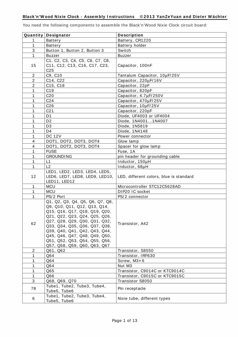
The polarity of the components D1, D2 and D3 must be observed! (anode and cathode) The polarity of the components must match the print on the board! The result should now look like this:

Now solder the larger parts, starting with the lowest first. These are: Battery holder Buzzer C1, C2, C3, C4, C5, C6, C7, C8, C11, C12, C13, C16, C17, C23, C25 C9, C10 C14, C22 C15, C18 C19 C20 C24 C26 C21 GROUNDING (pin header for grounding cable) L1 L2 MCU (IC socket only!) Q1, Q2, Q3, Q4, Q5, Q6, Q7, Q8, Q9, Q10, Q11, Q12, Q13, Q14, Q15, Q16, Q17, Q18, Q19, Q20, Q21, Q22, Q23, Q24, Q25, Q26, Q27, Q28, Q29, Q30, Q31, Q32, Q33, Q34, Q35, Q36, Q37, Q38, Q39, Q40, Q41, Q42, Q43, Q44, Q45, Q46, Q47, Q48, Q49, Q50, Q51, Q52, Q53, Q54, Q55, Q56, Q57, Q58, Q59, Q60, Q63, Q67 Q61, Q62 Q64 (use the screw and the nut for mounting Q64!) Q65 Q66 Q68, Q69, Q70 U1, U2, U3, U4, U5, U6, U7, U8 U11 U12, U13 Y2 The polarity of the components Buzzer, C9, C10, C14, C22, C20, C24 and C26 must be observed! (plus and minus) The polarity of the components must match the print on the board! C9, C10: The longer wire is +.

Page 4 of 13

Black’n’Wood Nixie Clock - Assembly Instructions ©2013 YanZeYuan and Dieter Wächter

Note for Y2: put the glass beads over the leads of Y2 to avoid overheating and solder shorts:

The result should now look like this:

Apply all tube contacts to the tube pins:

Insert the tubes one after another with the contacts into the drills of the board and align the tubes right-angled to the board surface. Solder the contacts carefully from the bottom side. Don’t use too much solder, otherwise the solder may flow into the inner side of the contacts. Cut ONLY the thin part of the contacts. Then pull the tubes out of the sockets again.

Page 5 of 13

Black’n’Wood Nixie Clock - Assembly Instructions ©2013 YanZeYuan and Dieter Wächter

The result should now look like this:

Solder the LEDs to the board. The polarity of the LEDs must be observed! (anode and cathode). The long lead is the anode; the short lead is the cathode. The polarity of the LEDs must match the print on the board! Very important: The distance between LEDs and tube bottom should be kept small as shown here:

Please do not heat the LEDs too long. Heating the LEDs too long would damage them.

Page 6 of 13

Black’n’Wood Nixie Clock - Assembly Instructions ©2013 YanZeYuan and Dieter Wächter

The result should now look like this:

Now put the spacers for the glow lamps over the glow lamp leads and solder them to the PCB. The 2 small holes in the spacers must point to the front. The result should now look like this:

Page 7 of 13

Black’n’Wood Nixie Clock - Assembly Instructions ©2013 YanZeYuan and Dieter Wächter

Now solder the 3 switches, the power connector and the PS/2 connector at the other side of the PCB. The result should now look like this:

Finally put the tubes and the controller into their sockets. Place the battery into the battery holder. The result should now look like this:

Your Black’n’Wood circuit board is now completed. Congratulations!

Page 8 of 13

Black’n’Wood Nixie Clock - Assembly Instructions ©2013 YanZeYuan and Dieter Wächter

Case Installation of the Black’n’Wood Nixie Clock You need the following components to mount the Black’n’Wood PCB in the case: Quantity Description

1 Wooden frame 1 Front panel 1 Back plate 4 Polyamide screw M3×30 5 Spacer, M3×12 5 Washer M3 10 Screw, M3×6 1 Screw, M3×5 4 Self tapping pan head screw, 2.9×9.5 mm 4 Rubber bumpon 3 Foam rubber 1 Wire, with plug for GND connector 1 Cable lug 1 Heat shrinking tube

Mount the 5 spacers (M3×12) with 5 screws M3×6 and 5 washers between PCB and spacer on the PCB. The result should now look like this:

Mount this assembly to the back plate with 5 screws M3×6. The result should now look like this:

Check the fastening parts with the help of the left picture.

Page 9 of 13

Black’n’Wood Nixie Clock - Assembly Instructions ©2013 YanZeYuan and Dieter Wächter

Put the foam rubber over the tubes, but put it as far as possible on the front of the tubes, so that the foam rubber will be moved in place automatically when inserting the assembly later in the case. The result should now look like this:

Now put the heat shrinking tube over the wire for the GND connector, solder the cable lug to the wire for the GND connector and heat shrink the heat shrinking tube over the solder tab. The result should look like this:

Now mount the grounding cable with a screw M3×5 (not M3×6!) on the front panel as shown:

Page 10 of 13

Black’n’Wood Nixie Clock - Assembly Instructions ©2013 YanZeYuan and Dieter Wächter

Apply the rubber bumpons on the bottom of the wooden frame on the positions shown in the following sketch. Choose the side with the worse wood texture.

The result should look like this:

Now mount the front panel with the 4 polyamide screws M3×30 on the wooden frame. Note: the GND connection must be on top (at the opposite of the rubber bumpons) The result should look like this:

Connect the grounding wire to the PCB:

Page 11 of 13

Black’n’Wood Nixie Clock - Assembly Instructions ©2013 YanZeYuan and Dieter Wächter

Mount the PCB assembly with the 4 self tapping pan head screw, 2.9×9.5 mm on the wooden frame:

Now it’s time to test your beautiful new Black’n’Wood Nixie Clock!! Have fun!!

To clean the surface of the housing and the tubes use a snooth microfiber cloth.

Page 12 of 13

Black’n’Wood Nixie Clock - Assembly Instructions ©2013 YanZeYuan and Dieter Wächter

Notes on the AUX output: The AUX output is an open collector output and is on pin 3 of the PS/2 (Mini DIN) connector. The circuit is as follows:

You can either use the open collector output, or install a pull up resistor for R90. The maximum current to be drawn from the +5 V source, is 50 mA. The maximum load current of the transistor is 100 mA! Notes on the PS/2 (Mini DIN) Socket Here is some information about the MINI DIN Socket that is mounted on the back of the clock. Viewing direction is towards the socket

Pin Connection

Shield GND 1 GND 2 +5V DC (50 mA maximal) 3 AUX out (open collector) 4 Not used 5 TxT (DCF and GPS input) 6 Internal use, do not connect!

Notes on cables switch or switched outlet If you want the clock to run only occasionally, you may do so via a switched outlet or cord switch. Plug in the power supply into a switched outlet or simply build up a cord switch in the power supply cable. The internal battery is not discharged faster than normal and it has absolutely no negative effects on the circuit or the tubes.

Page 13 of 13


Recommended