58
BladeCenter and BladeCenter T Serial over LAN Setup Guide E Rserver

BladeCenter
and
BladeCenter
T
Serial
over
LAN
Setup
Guide
ERserver
���


BladeCenter
and
BladeCenter
T
Serial
over
LAN
Setup
Guide
ERserver
���

Note:
Before
using
this
information
and
the
product
it
supports,
read
the
general
information
in
Appendix
A,
“Getting
help
and
technical
assistance,”
on
page
45
and
Appendix
B,
“Notices,”
on
page
47.
Third
Edition
(June
2004)
©
Copyright
International
Business
Machines
Corporation
2004.
All
rights
reserved.
US
Government
Users
Restricted
Rights
–
Use,
duplication
or
disclosure
restricted
by
GSA
ADP
Schedule
Contract
with
IBM
Corp.

Contents
Chapter
1.
Introduction
.
.
.
.
.
.
.
.
.
.
.
.
.
.
.
.
.
.
.
.
.
. 1
Hardware
and
firmware
requirements
.
.
.
.
.
.
.
.
.
.
.
.
.
.
.
.
. 2
Hardware
requirements
.
.
.
.
.
.
.
.
.
.
.
.
.
.
.
.
.
.
.
.
. 2
Firmware
requirements
.
.
.
.
.
.
.
.
.
.
.
.
.
.
.
.
.
.
.
.
. 3
Checking
firmware
versions
.
.
.
.
.
.
.
.
.
.
.
.
.
.
.
.
.
.
.
. 5
Chapter
2.
General
configuration
.
.
.
.
.
.
.
.
.
.
.
.
.
.
.
.
.
. 7
Starting
the
BladeCenter
management-module
Web
interface
.
.
.
.
.
.
.
. 7
Global
SOL
settings
and
status
.
.
.
.
.
.
.
.
.
.
.
.
.
.
.
.
.
.
. 8
Configuring
the
global
SOL
settings
for
the
BladeCenter
unit
.
.
.
.
.
.
.
. 10
Linux
configuration
.
.
.
.
.
.
.
.
.
.
.
.
.
.
.
.
.
.
.
.
.
.
. 11
Red
Hat
Enterprise
Linux
ES
2.1
configuration
.
.
.
.
.
.
.
.
.
.
.
. 11
SUSE
SLES
8.0
configuration
.
.
.
.
.
.
.
.
.
.
.
.
.
.
.
.
.
. 17
Microsoft
Windows
2003
Standard
Edition
configuration
.
.
.
.
.
.
.
.
.
. 19
Installing
and
configuring
SSH
for
SOL
.
.
.
.
.
.
.
.
.
.
.
.
.
.
.
. 21
Completing
the
SOL
configuration
.
.
.
.
.
.
.
.
.
.
.
.
.
.
.
.
.
. 21
Chapter
3.
Component-specific
configuration
.
.
.
.
.
.
.
.
.
.
.
. 23
Configuring
the
management
module
.
.
.
.
.
.
.
.
.
.
.
.
.
.
.
.
. 23
Configuring
the
IBM
Eserver
BladeCenter
HS20
Type
8832
blade
server
.
.
. 25
SOL
jumper
placement
.
.
.
.
.
.
.
.
.
.
.
.
.
.
.
.
.
.
.
.
. 26
Updating
and
configuring
the
BIOS
.
.
.
.
.
.
.
.
.
.
.
.
.
.
.
. 26
Updating
the
integrated
systems
management
processor
firmware
.
.
.
.
. 27
Updating
the
Broadcom
Ethernet
controller
firmware
.
.
.
.
.
.
.
.
.
. 28
Installing
the
Broadcom
Ethernet
controller
device
driver
for
Linux
operating
systems
.
.
.
.
.
.
.
.
.
.
.
.
.
.
.
.
.
.
.
.
.
.
.
.
. 28
Configuring
the
IBM
Eserver
BladeCenter
HS40
Type
8839
blade
server
.
.
. 28
Updating
the
Baseboard
Management
Controller
firmware
.
.
.
.
.
.
.
. 29
Updating
the
programmable
logic
device
firmware
.
.
.
.
.
.
.
.
.
.
. 29
Updating
and
configuring
the
BIOS
.
.
.
.
.
.
.
.
.
.
.
.
.
.
.
. 29
Installing
the
Intel
Ethernet
controller
device
driver
for
Linux
operating
systems
.
.
.
.
.
.
.
.
.
.
.
.
.
.
.
.
.
.
.
.
.
.
.
.
. 30
Configuring
the
IBM
Eserver
BladeCenter
JS20
Type
8842
blade
server
.
.
. 30
Updating
the
open
firmware
(BIOS)
.
.
.
.
.
.
.
.
.
.
.
.
.
.
.
. 31
Updating
the
integrated
systems
management
processor
firmware
.
.
.
.
. 31
Updating
the
Broadcom
Ethernet
controller
firmware
.
.
.
.
.
.
.
.
.
. 31
Installing
the
Broadcom
Ethernet
controller
device
driver
for
Linux
operating
systems
.
.
.
.
.
.
.
.
.
.
.
.
.
.
.
.
.
.
.
.
.
.
.
.
. 32
Configuring
the
IBM
4-Port
Gb
Ethernet
Switch
Module
for
BladeCenter
.
.
.
. 32
Configuring
the
Nortel
Networks
Layer
2-7
GbE
Switch
Module
for
IBM
Eserver
BladeCenter
.
.
.
.
.
.
.
.
.
.
.
.
.
.
.
.
.
.
.
.
. 33
Configuring
the
Cisco
Systems
Intelligent
Gigabit
Ethernet
Switch
Module
for
the
IBM
Eserver
BladeCenter
.
.
.
.
.
.
.
.
.
.
.
.
.
.
.
.
.
. 33
Chapter
4.
Using
SOL
.
.
.
.
.
.
.
.
.
.
.
.
.
.
.
.
.
.
.
.
.
. 37
Starting
an
SOL
session
.
.
.
.
.
.
.
.
.
.
.
.
.
.
.
.
.
.
.
.
. 37
Starting
a
command-line
Telnet
connection
.
.
.
.
.
.
.
.
.
.
.
.
. 37
Starting
a
command-line
Secure
Shell
(SSH)
connection
.
.
.
.
.
.
.
. 38
Starting
an
SOL
session
from
the
command-line
interface
.
.
.
.
.
.
.
. 38
Ending
an
SOL
session
.
.
.
.
.
.
.
.
.
.
.
.
.
.
.
.
.
.
.
.
.
. 39
Restarting
a
blade
server
through
SOL
.
.
.
.
.
.
.
.
.
.
.
.
.
.
.
. 39
Mounting
and
unmounting
media
for
Linux
operating
systems
.
.
.
.
.
.
.
. 40
©
Copyright
IBM
Corp.
2004
iii

Mounting
and
unmounting
media
for
the
BladeCenter
HS20
Type
8832
blade
server
and
the
BladeCenter
HS40
Type
8839
blade
server
.
.
.
.
.
.
. 40
Mounting
and
unmounting
media
for
the
BladeCenter
JS20
Type
8842
blade
server
.
.
.
.
.
.
.
.
.
.
.
.
.
.
.
.
.
.
.
.
.
.
.
.
.
. 42
Appendix
A.
Getting
help
and
technical
assistance
.
.
.
.
.
.
.
.
.
. 45
Before
you
call
.
.
.
.
.
.
.
.
.
.
.
.
.
.
.
.
.
.
.
.
.
.
.
.
. 45
Using
the
documentation
.
.
.
.
.
.
.
.
.
.
.
.
.
.
.
.
.
.
.
.
. 45
Getting
help
and
information
from
the
World
Wide
Web
.
.
.
.
.
.
.
.
.
. 45
Software
service
and
support
.
.
.
.
.
.
.
.
.
.
.
.
.
.
.
.
.
.
. 46
Hardware
service
and
support
.
.
.
.
.
.
.
.
.
.
.
.
.
.
.
.
.
.
. 46
Appendix
B.
Notices
.
.
.
.
.
.
.
.
.
.
.
.
.
.
.
.
.
.
.
.
.
. 47
Edition
notice
.
.
.
.
.
.
.
.
.
.
.
.
.
.
.
.
.
.
.
.
.
.
.
.
. 47
Trademarks
.
.
.
.
.
.
.
.
.
.
.
.
.
.
.
.
.
.
.
.
.
.
.
.
.
. 48
Index
.
.
.
.
.
.
.
.
.
.
.
.
.
.
.
.
.
.
.
.
.
.
.
.
.
.
.
. 49
iv
BladeCenter
and
BladeCenter
T:
Serial
over
LAN
Setup
Guide

Chapter
1.
Introduction
The
IBM®
ERserver
BladeCenter™
and
IBM
Eserver
BladeCenter
T
management
module
command-line
interfaces
provide
access
to
the
text-console
command
prompt
on
each
blade
server
through
a
Serial
over
LAN
(SOL)
connection,
enabling
the
blade
servers
to
be
managed
from
a
remote
location.
This
document
explains
how
to
update
and
configure
BladeCenter
and
BladeCenter
T
components
for
SOL
operation
using
the
BladeCenter
or
BladeCenter
T
management-module
Web
interface.
You
can
also
perform
many
configuration
procedures
using
the
management-module
command-line
interface
or
the
simple
network
management
protocol
(SNMP).
See
the
IBM
Eserver
BladeCenter
and
BladeCenter
T
Management
Module
Command-Line
Interface
Reference
Guide
for
information
about
the
management-module
command-line
interface
and
instructions
about
how
to
use
it.
The
IBM
Eserver
BladeCenter
and
IBM
Eserver
BladeCenter
T
units
are
also
referred
to
throughout
this
document
as
the
BladeCenter
unit.
Unless
stated
otherwise,
all
descriptions
and
instructions
in
this
document
apply
to
both
the
BladeCenter
and
BladeCenter
T
configurations.
In
the
BladeCenter
environment,
the
integrated
system
management
processor
(ISMP)
and
network
interface
controller
(NIC)
on
each
blade
server
routes
the
serial
data
from
the
blade
server
serial
communications
port
to
the
network
infrastructure
of
the
BladeCenter
unit,
including
an
Ethernet-compatible
I/O
module
that
supports
SOL
communication.
BladeCenter
components
are
configured
for
SOL
operation
through
the
BladeCenter
management
module.
The
management
module
also
acts
as
a
proxy
in
the
network
infrastructure
to
couple
a
client
running
a
Telnet
session
with
the
management
module
to
an
SOL
session
running
on
a
blade
server,
enabling
the
Telnet
client
to
interact
with
the
serial
port
of
the
blade
server
over
the
network.
Because
all
SOL
traffic
is
controlled
by
and
routed
through
the
management
module,
administrators
can
segregate
the
management
traffic
for
the
BladeCenter
unit
from
the
data
traffic
of
the
blade
servers.
To
start
an
SOL
connection
with
a
blade
server,
you
must
first
start
a
Telnet
command-line
interface
session
with
the
management
module.
When
this
Telnet
command-line
interface
session
is
running,
you
can
start
a
remote-console
SOL
session
with
any
blade
server
in
the
BladeCenter
unit
that
is
set
up
and
enabled
for
SOL
operation.
You
can
establish
up
to
20
separate
Telnet
sessions
with
a
BladeCenter
management
module.
For
a
BladeCenter
unit,
this
enables
you
to
have
14
simultaneous
SOL
sessions
active
(one
for
each
of
up
to
14
blade
servers)
with
6
additional
command-line
interface
sessions
available
for
BladeCenter
unit
management.
For
a
BladeCenter
T
unit,
this
enables
you
to
have
8
simultaneous
SOL
sessions
active
(one
for
each
of
up
to
8
blade
servers)
with
12
additional
command-line
interface
sessions
available
for
BladeCenter
unit
management.
If
security
is
a
concern,
you
can
use
Secure
Shell
(SSH)
sessions
to
establish
secure
Telnet
command-line
interface
sessions
with
the
BladeCenter
management
module
before
starting
an
SOL
console
redirect
session
with
a
blade
server.
The
most
recent
versions
of
all
BladeCenter
and
BladeCenter
T
documentation
are
available
from
the
IBM
Web
site.
Complete
the
following
steps
to
check
for
updated
BladeCenter
or
BladeCenter
T
documentation
and
technical
updates:
1.
Go
to
http://www.ibm.com/pc/support/.
2.
In
the
Learn
section,
click
Online
publications.
3.
On
the
“Online
publications”
page,
in
the
Brand
field,
select
Servers.
4.
In
the
Family
field,
select
BladeCenter
or
BladeCenter
T.
5.
Click
Continue.
©
Copyright
IBM
Corp.
2004
1

Hardware
and
firmware
requirements
The
BladeCenter
unit
must
be
correctly
configured
before
you
can
use
the
command-line
interface
and
SOL.
This
section
describes
the
hardware
and
software
that
are
required
for
the
command-line
interface
and
SOL.
Hardware
requirements
The
following
hardware
is
required
for
SOL
operation.
Compatibility
between
BladeCenter
components
that
are
used
for
SOL
is
listed
in
Table
1
on
page
3.
v
An
SOL-capable
blade
server.
(The
IBM
Eserver
BladeCenter
HS20
Type
8678
blade
server
does
not
support
SOL
operation.)
You
can
use
the
console
command
to
control
a
blade
server
through
SOL
only
on
blade
server
types
that
support
SOL
functionality
that
have
the
required
firmware
levels
(see
Table
2
on
page
4).
v
An
SOL-capable
Ethernet
I/O
module
installed
in
I/O-module
bay
1.
As
of
the
date
of
this
document,
the
only
I/O
modules
that
support
SOL
operation
are:
–
IBM
4-Port
Gb
Ethernet
Switch
Module
for
BladeCenter
–
Nortel
Networks
Layer
2-7
GbE
Switch
Module
for
IBM
Eserver
BladeCenter
(as
of
the
date
of
this
publication,
this
I/O
module
is
only
qualified
for
use
with
the
BladeCenter
HS20
Type
8832
and
the
BladeCenter
HS40
Type
8839
blade
servers)
–
Cisco
Systems
Intelligent
Gigabit
Ethernet
Switch
Module
for
the
IBM
Eserver
BladeCenter
(as
of
the
date
of
this
publication,
this
I/O
module
is
only
qualified
for
use
with
the
BladeCenter
HS20
Type
8832
and
the
BladeCenter
HS40
Type
8839
blade
servers)
v
For
the
IBM
Eserver
BladeCenter
HS20
Type
8832
blade
server:
–
SOL
uses
the
first
network
interface,
Ethernet
1
(eth1
or
Planar
Ethernet
1),
of
the
blade
server
to
communicate.
When
this
network
interface
attempts
to
boot
through
PXE
or
DHCP,
the
network
interface
is
reset,
causing
the
current
SOL
session
to
be
dropped
and
have
a
new
status
of
Not
Ready.
If
you
require
booting
through
PXE
or
DHCP,
use
the
second
network
interface,
Ethernet
2
(eth2
or
Planar
Ethernet
2),
of
the
blade
server
and
install
an
SOL-capable
Ethernet
I/O
module
in
I/O-module
bay
1.
–
Jumper
J28
on
the
BladeCenter
HS20
Type
8832
blade
server
must
be
installed
in
the
correct
position.
See
“SOL
jumper
placement”
on
page
26
for
information.
v
For
the
IBM
Eserver
BladeCenter
JS20
Type
8842
blade
server,
SOL
uses
the
first
network
interface,
Ethernet
1
(eth1
or
Planar
Ethernet
1),
of
the
blade
server
to
communicate.
When
this
network
interface
attempts
to
use
BOOTP,
the
network
interface
is
reset,
causing
the
current
SOL
session
to
be
dropped
and
have
a
new
status
of
Not
Ready.
If
you
require
BOOTP,
use
the
second
network
interface,
Ethernet
2
(eth2
or
Planar
Ethernet
2),
of
the
blade
server
and
install
an
SOL-capable
Ethernet
I/O
module
in
I/O-module
bay
1.
2
BladeCenter
and
BladeCenter
T:
Serial
over
LAN
Setup
Guide

Table
1.
SOL
hardware
compatibility
I/O
Module
Blade
server
Bla
deC
ente
r
HS
20
Typ
e
8832
b
lad
e
serv
er
Bla
deC
ente
r
HS
40
Typ
e
8839
b
lad
e
serv
er
Bla
deC
ente
r
JS20
Typ
e
8842
b
lad
e
serv
er
IBM
4-Port
Gb
Ethernet
Switch
Module
for
BladeCenter
v
v
v
Nortel
Networks
Layer
2-7
GbE
Switch
Module
for
IBM
Eserver
BladeCenter
v
v
Cisco
Systems
Intelligent
Gigabit
Ethernet
Switch
Module
for
the
IBM
Eserver
BladeCenter
v
v
Firmware
requirements
Make
sure
that
you
are
using
the
latest
versions
of
device
drivers,
firmware,
and
BIOS
for
your
blade
server,
management
module,
and
other
BladeCenter
components.
Go
to
the
IBM
Support
Web
site,
http://www.ibm.com/pc/support/,
for
the
latest
information
about
upgrading
the
device
drivers,
firmware,
and
BIOS
for
BladeCenter
components.
The
latest
instructions
are
in
the
documentation
that
comes
with
the
updates.
The
following
table
lists
the
firmware
levels
that
are
required
for
BladeCenter
components
to
support
SOL
operation.
Chapter
1.
Introduction
3

Table
2.
Firmware
levels
required
for
SOL
Component
Firmware
level
IBM
Eserver
BladeCenter
Management
Module
1.08
or
later
IBM
Eserver
BladeCenter
T
Management
Module
All
firmware
versions
support
SOL
Bla
deC
ente
r
HS
20
Type
88
32
blad
e
serv
er
IBM
Eserver
BladeCenter
HS20
Type
8832
blade
server
BIOS
1.03
or
later
IBM
Eserver
BladeCenter
HS20
Type
8832
blade
server
diagnostics
1.02
or
later
IBM
Eserver
BladeCenter
HS20
Type
8832
blade
server
ISMP
1.03
or
later
IBM
Eserver
BladeCenter
HS20
Type
8832
blade
server
Broadcom
Ethernet
Controller
Boot
ROM
3.21
or
later
IBM
Eserver
BladeCenter
HS20
Type
8832
blade
server
Broadcom
Ethernet
Controller
Firmware
2.2
or
later
IBM
Eserver
BladeCenter
HS20
Type
8832
blade
server
Broadcom
Ethernet
Controller
Diagnostic
Utility
1.06
or
later
IBM
Eserver
BladeCenter
HS20
Type
8832
blade
server
Broadcom
Ethernet
Controller
Linux
Device
Driver
7.1.22
or
later
Bla
deC
ente
r
HS
40
Type
88
39
blad
e
serv
er
IBM
Eserver
BladeCenter
HS40
Type
8839
blade
server
BIOS
See
the
IBM
Support
Web
site
1
IBM
Eserver
BladeCenter
HS40
Type
8839
blade
server
BMC
See
the
IBM
Support
Web
site
1
IBM
Eserver
BladeCenter
HS40
Type
8839
blade
server
PLD
See
the
IBM
Support
Web
site
1
IBM
Eserver
BladeCenter
HS40
Type
8839
blade
server
Intel™
Ethernet
Controller
Linux
Device
Driver
See
the
IBM
Support
Web
site
1
Bla
deC
ente
r
JS20
Type
88
42
blad
e
serv
er
IBM
Eserver
BladeCenter
JS20
Type
8842
blade
server
open
firmware
(BIOS)
See
the
IBM
Support
Web
site
1
IBM
Eserver
BladeCenter
JS20
Type
8842
blade
server
ISMP
See
the
IBM
Support
Web
site
1
IBM
Eserver
BladeCenter
JS20
Type
8842
blade
server
Broadcom
Ethernet
Controller
Firmware
See
the
IBM
Support
Web
site
1
IBM
Eserver
BladeCenter
JS20
Type
8842
blade
server
Broadcom
Ethernet
Controller
Linux
Device
Driver
See
the
IBM
Support
Web
site
1
IBM
4-Port
Gb
Ethernet
Switch
Module
for
BladeCenter
1.04
or
later
Nortel
Networks
Layer
2-7
GbE
Switch
Module
for
IBM
Eserver
BladeCenter
See
the
IBM
Support
Web
site
1
Cisco
Systems
Intelligent
Gigabit
Ethernet
Switch
Module
for
the
IBM
Eserver
BladeCenter
All
firmware
versions
support
SOL
Note
1:
Go
to
the
IBM
Support
Web
site,
http://www.ibm.com/pc/support/,
for
the
latest
information
about
firmware
levels
that
support
SOL.
4
BladeCenter
and
BladeCenter
T:
Serial
over
LAN
Setup
Guide

Checking
firmware
versions
Complete
the
following
steps
to
view
the
firmware
levels
that
are
installed
in
the
BladeCenter
components:
1.
Start
the
BladeCenter
management-module
Web
interface
(see
“Starting
the
BladeCenter
management-module
Web
interface”
on
page
7).
2.
In
the
navigation
pane,
click
Monitors
→
Firmware
VPD.
The
Firmware
VPD
choice
identifies
the
firmware
type,
build
ID,
release
date,
and
revision
number
for
the
firmware
that
is
installed
in
each
blade
server,
I/O
module,
and
management
module
in
the
BladeCenter
unit.
The
vital
product
data
(VPD)
for
the
firmware
in
the
management
modules
also
includes
the
file
name
of
the
firmware
components.
(Selecting
the
Firmware
VPD
choice
takes
up
to
30
seconds
to
refresh
and
display
information.)
Important:
To
avoid
problems
and
to
maintain
proper
system
performance,
always
make
sure
that
the
blade
server
firmware
code,
service
processor
code,
and
diagnostic
firmware
code
levels
are
consistent
for
all
blade
servers
within
the
BladeCenter
unit.
Compare
the
installed
firmware
version
to
the
information
in
Table
2
on
page
4
and
to
the
firmware
information
on
the
IBM
Support
Web
site
at
http://www.ibm.com/pc/support/.
If
the
firmware
versions
match,
your
blade
server
has
the
firmware
code
needed
to
use
the
SOL
feature.
If
installed
firmware
versions
do
not
meet
at
least
the
minimum
requirements,
download
the
latest
firmware
code
from
the
IBM
Support
Web
site
and
install
it
following
the
firmware
update
instructions
for
each
BladeCenter
component
in
Chapter
3,
“Component-specific
configuration,”
on
page
23.
Chapter
1.
Introduction
5

6
BladeCenter
and
BladeCenter
T:
Serial
over
LAN
Setup
Guide

Chapter
2.
General
configuration
Note:
The
sample
screens
that
appear
in
this
document
might
differ
slightly
from
the
screens
displayed
by
your
system.
Screen
content
varies
based
on
the
type
of
BladeCenter
unit
that
you
are
using
and
the
options
that
are
installed.
This
section
provides
instructions
for
configuring
the
BladeCenter
unit
to
operate
using
SOL.
You
must
perform
the
following
configuration
procedures:
v
Configure
the
BladeCenter
unit
for
SOL
operation
(see
“Configuring
the
global
SOL
settings
for
the
BladeCenter
unit”
on
page
10).
v
Configure
BladeCenter
components
for
SOL
operation
(see
Chapter
3,
“Component-specific
configuration,”
on
page
23).
v
Configure
the
operating
system
that
is
installed
on
each
blade
server
to
enable
SOL
(see
“Linux
configuration”
on
page
11
and
“Microsoft
Windows
2003
Standard
Edition
configuration”
on
page
19).
v
If
secure
SOL
sessions
are
required,
install
and
configure
SSH
for
SOL
(see
“Installing
and
configuring
SSH
for
SOL”
on
page
21).
v
Enable
blade
servers
for
SOL
operation
(see
“Completing
the
SOL
configuration”
on
page
21).
Perform
the
SOL
configuration
that
is
shared
by
all
BladeCenter
components
using
the
management-module
Web
interface.
The
management-module
Web
interface
supports
only
configuration
and
monitoring
of
the
command-line
interface
and
SOL
and
cannot
be
used
to
start
command-line
interface
or
SOL
sessions.
You
can
also
perform
some
SOL
configuration
using
the
management-module
command-line
interface
or
the
Simple
Network
Management
Protocol
(SNMP).
See
the
IBM
Eserver
BladeCenter
and
BladeCenter
T
Management
Module
Command-Line
Interface
Reference
Guide
for
information
about
the
management-module
command-line
interface
and
instructions
for
using
it.
Starting
the
BladeCenter
management-module
Web
interface
Complete
the
following
steps
to
start
the
BladeCenter
management-module
Web
interface:
1.
Open
a
Web
browser.
In
the
address
or
URL
field,
type
the
IP
address
or
host
name
that
is
assigned
for
the
management-module
remote
connection.
The
Enter
Network
Password
window
opens.
2.
Type
your
user
name
and
password.
If
you
are
logging
in
to
the
management
module
for
the
first
time,
you
can
obtain
your
user
name
and
password
from
your
system
administrator.
All
login
attempts
are
documented
in
the
event
log.
The
initial
user
ID
and
password
for
the
management
module
are:
v
User
ID:
USERID
(all
capital
letters)
v
Password:
PASSW0RD
(note
the
zero,
not
O,
in
PASSW0RD)
3.
Follow
the
instructions
on
the
screen.
Be
sure
to
set
the
timeout
value
that
you
want
for
your
Web
session.
©
Copyright
IBM
Corp.
2004
7
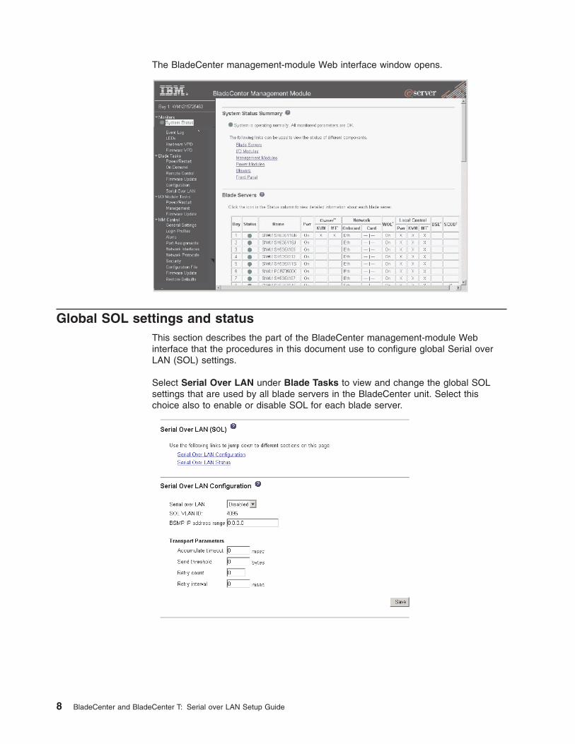
The
BladeCenter
management-module
Web
interface
window
opens.
Global
SOL
settings
and
status
This
section
describes
the
part
of
the
BladeCenter
management-module
Web
interface
that
the
procedures
in
this
document
use
to
configure
global
Serial
over
LAN
(SOL)
settings.
Select
Serial
Over
LAN
under
Blade
Tasks
to
view
and
change
the
global
SOL
settings
that
are
used
by
all
blade
servers
in
the
BladeCenter
unit.
Select
this
choice
also
to
enable
or
disable
SOL
for
each
blade
server.
8
BladeCenter
and
BladeCenter
T:
Serial
over
LAN
Setup
Guide

Unless
otherwise
noted,
the
default
management-module
SOL
settings
provide
the
best
overall
SOL
performance.
You
can
modify
these
settings
to
meet
requirements
that
are
specific
to
your
BladeCenter
unit
or
network
configuration.
The
default
SOL
values
are:
v
Serial
Over
Lan:
Enabled
Use
this
field
to
enable
or
disable
SOL
globally
for
the
BladeCenter
unit.
Enabling
or
disabling
SOL
globally
does
not
affect
the
SOL
session
status
for
each
blade
server.
v
SOL
VLAN
ID
–
For
the
IBM
4-Port
Gb
Ethernet
Switch
Module
for
BladeCenter
and
the
Nortel
Networks
Layer
2-7
GbE
Switch
Module
for
IBM
Eserver
BladeCenter
the
SOL
VLAN
ID
must
be
set
to
4095.
–
For
the
Cisco
Systems
Intelligent
Gigabit
Ethernet
Switch
Module
for
the
IBM
Eserver
BladeCenter
the
SOL
VLAN
ID
can
be
set
to
any
value
between
3
and
1001:
it
cannot
be
set
to
the
default
value
of
4095.
Write
down
this
value
for
use
when
configuring
the
Cisco
Systems
Intelligent
Gigabit
Ethernet
Switch
Module.
v
BSMP
IP
Address
Range:
x.x.x.x
This
is
a
mandatory
field
where
x.x.x.x
is
the
base
IP
address
for
blade
servers
in
the
BladeCenter
unit.
The
IP
address
that
SOL
uses
to
communicate
with
the
blade
system
management
processor
(BSMP)
of
each
blade
server
is
based
on
the
IP
address
that
is
set
in
this
field.
For
example,
if
the
value
that
you
enter
is
10.1.1.1,
the
blade
server
in
blade
bay
1
will
have
IP
address
10.1.1.1,
the
blade
server
in
blade
bay
2
will
have
IP
address
10.1.1.2,
and
so
on.
v
Accumulate
timeout:
25
(default
value
is
5)
v
Send
threshold:
250
v
Retry
count:
3
v
Retry
interval:
2500
(default
value
is
250)
Chapter
2.
General
configuration
9

Use
the
Serial
Over
LAN
Status
table
to
monitor
the
SOL
status
for
each
blade
server
and
to
enable
or
disable
SOL
for
each
blade
server.
SOL
must
be
enabled
both
globally
for
the
BladeCenter
unit
and
individually
for
each
blade
server
where
you
plan
to
start
an
SOL
session.
SOL
is
enabled
globally
and
on
blade
servers
by
default.
The
SOL
Session
status
has
three
possible
states:
Not
ready
This
status
indicates
that
no
SOL
session
is
available
between
the
management
module
and
the
blade
server.
It
might
indicate
that
there
was
an
SOL
session
setup
failure
that
must
be
investigated.
Ready
This
status
indicates
that
an
SOL
session
is
established
between
the
management
module
and
the
blade
server.
This
SOL
session
is
available
to
connect
to
a
Telnet
session,
if
one
is
requested
by
the
user.
Active
This
status
indicates
that
there
is
an
SOL
session
between
the
management
module
and
the
blade
server
and
that
this
session
is
currently
connected
to
a
Telnet
session.
Configuring
the
global
SOL
settings
for
the
BladeCenter
unit
Complete
the
following
steps
to
configure
the
global
SOL
settings
for
the
BladeCenter
unit:
1.
Start
the
BladeCenter
management-module
Web
interface
(see
“Starting
the
BladeCenter
management-module
Web
interface”
on
page
7).
2.
In
the
navigation
pane,
click
Blade
Tasks
→
Serial
Over
LAN.
In
the
management-module
information
page
that
opens,
make
sure
that
the
settings
match
the
default
values
that
are
listed
starting
on
page
9
or
are
set
to
the
values
that
are
required
by
your
network
configuration.
10
BladeCenter
and
BladeCenter
T:
Serial
over
LAN
Setup
Guide

Linux
configuration
For
SOL
operation
on
the
BladeCenter
HS20
Type
8832
blade
server
and
the
BladeCenter
HS40
Type
8839
blade
server,
you
must
configure
the
Linux
operating
system
to
expose
the
Linux
initialization
(booting)
process.
This
enables
users
to
log
in
to
the
Linux
console
using
an
SOL
session
and
directs
Linux
output
to
the
serial
console.
See
the
documentation
for
your
specific
Linux
operating-system
type
for
information
and
instructions.
You
do
not
have
to
configure
the
Linux
operating
system
when
using
a
BladeCenter
JS20
Type
8842
blade
server.
Complete
one
of
the
following
procedures
to
enable
SOL
sessions
for
your
Linux
operating
system.
You
must
be
logged
in
as
a
root
user
to
perform
these
procedures.
Red
Hat
Enterprise
Linux
ES
2.1
configuration
Note:
This
procedure
is
based
on
a
default
installation
of
Red
Hat
Enterprise
Linux
ES
2.1.
The
file
names,
structures,
and
commands
might
be
different
for
other
versions
of
Red
Hat
Linux.
Complete
the
following
steps
to
configure
the
general
Linux
parameters
for
SOL
operation
when
using
the
Red
Hat
Enterprise
Linux
ES
2.1
operating
system.
Note:
Hardware
flow
control
prevents
character
loss
during
communication
over
a
serial
connection.
You
must
enable
it
when
using
a
Linux
operating
system.
1.
Add
the
following
line
to
the
end
of
the
#
Run
gettys
in
standard
runlevels
section
of
the
/etc/inittab
file.
This
enables
hardware
flow
control
and
enables
users
to
log
in
through
the
SOL
console.
7:2345:respawn:/sbin/agetty
-h
ttyS1
19200
vt102
2.
Add
the
following
line
at
the
bottom
of
the
/etc/securetty
file
to
enable
a
user
to
log
in
as
the
root
user
through
the
SOL
console:
ttyS1
LILO
configuration
If
you
are
using
LILO,
complete
the
following
steps:
1.
Complete
the
following
steps
to
modify
the
/etc/lilo.conf
file:
a.
Add
the
following
text
to
the
end
of
the
first
default=linux
line
-Monitor
b.
Comment
out
the
map=/boot/map
line
by
adding
a
#
at
the
beginning
of
this
line.
c.
Comment
out
the
message=/boot/message
line
by
adding
a
#
at
the
beginning
of
this
line.
d.
Add
the
following
line
before
the
first
image=...
line:
#
This
will
allow
you
to
only
Monitor
the
OS
boot
via
SOL
e.
Add
the
following
text
to
the
end
of
the
first
label=linux
line
-Monitor
f.
Add
the
following
line
to
the
first
image=...
section.
This
enables
SOL.
append="console=ttyS1,19200n8
console=tty1"
g.
Add
the
following
lines
between
the
two
image=...
sections:
#
This
will
allow
you
to
Interact
with
the
OS
boot
via
SOL
image=/boot/vmlinuz-2.4.9-e.12smp
label=linux-Interact
Chapter
2.
General
configuration
11

initrd=/boot/initrd-2.4.9-e.12smp.img
read-only
root=/dev/hda6
append="console=tty1
console=ttyS1,19200n8
"
The
following
samples
show
examples
of
the
original
content
of
the
/etc/lilo.conf
file
and
the
content
of
this
file
after
modification.
Original
/etc/lilo.conf
contents
prompt
timeout=50
default=linux
boot=/dev/hda
map=/boot/map
install=/boot/boot.b
message=/boot/message
linear
image=/boot/vmlinuz-2.4.9-e.12smp
label=linux
initrd=/boot/initrd-2.4.9-e.12smp.img
read-only
root=/dev/hda6
image=/boot/vmlinuz-2.4.9-e.12
label=linux-up
initrd=/boot/initrd-2.4.9-e.12.img
read-only
root=/dev/hda6
12
BladeCenter
and
BladeCenter
T:
Serial
over
LAN
Setup
Guide

Modified
/etc/lilo.conf
contents
prompt
timeout=50
default=linux-Monitor
boot=/dev/hda
#map=/boot/map
install=/boot/boot.b
#message=/boot/message
linear
#
This
will
allow
you
to
only
Monitor
the
OS
boot
via
SOL
image=/boot/vmlinuz-2.4.9-e.12smp
label=linux-Monitor
initrd=/boot/initrd-2.4.9-e.12smp.img
read-only
root=/dev/hda6
append="console=ttyS1,19200n8
console=tty1"
#
This
will
allow
you
to
Interact
with
the
OS
boot
via
SOL
image=/boot/vmlinuz-2.4.9-e.12smp
label=linux-Interact
initrd=/boot/initrd-2.4.9-e.12smp.img
read-only
root=/dev/hda6
append="console=tty1
console=ttyS1,19200n8
"
image=/boot/vmlinuz-2.4.9-e.12
label=linux-up
initrd=/boot/initrd-2.4.9-e.12.img
read-only
root=/dev/hda6
2.
Run
the
lilo
command
to
store
and
activate
the
LILO
configuration.
When
the
Linux
operating
system
starts,
a
LILO
boot:
prompt
is
displayed
instead
of
the
graphical
user
interface.
Pressing
Tab
while
at
this
prompt
will
install
all
of
the
boot
options
that
are
listed.
To
load
the
operating
system
in
interactive
mode,
type
linux-Interact
and
then
press
Enter.
GRUB
configuration
If
you
are
using
GRUB,
complete
the
following
steps
to
modify
the
/boot/grub/grub.conf
file:
1.
Comment
out
the
splashimage=...
line
by
adding
a
#
at
the
beginning
of
this
line.
2.
Add
the
following
line
before
the
first
title=...
line:
#
This
will
allow
you
to
only
Monitor
the
OS
boot
via
SOL
3.
Append
the
following
text
to
the
first
title=...
line:
SOL
Monitor
4.
Append
the
following
text
to
the
kernel/...
line
of
the
first
title=...
section:
console=ttyS1,19200
console=tty1
5.
Add
the
following
five
lines
between
the
two
title=...
sections:
#
This
will
allow
you
to
Interact
with
the
OS
boot
via
SOL
Chapter
2.
General
configuration
13

title
Red
Hat
Linux
(2.4.9-e.12smp)
SOL
Interactive
root
(hd0,0)
kernel
/vmlinuz-2.4.9-e.12smp
ro
root=/dev/hda6
console=tty1
console=ttyS1,19200
initrd
/initrd-2.4.9-e.12smp.img
Note:
The
entry
beginning
with
kernel
/vmlinuz...
is
shown
with
a
line
break
after
console=tty1.
In
your
file,
the
entire
entry
must
all
be
on
one
line.
The
following
samples
show
examples
of
the
original
content
of
the
/boot/grub/grub.conf
file
and
the
content
of
this
file
after
modification.
14
BladeCenter
and
BladeCenter
T:
Serial
over
LAN
Setup
Guide

Original
/boot/grub/grub.conf
contents
#grub.conf
generated
by
anaconda
#
#
Note
that
you
do
not
have
to
rerun
grub
after
making
changes
to
this
file
#
NOTICE:
You
have
a
/boot
partition.
This
means
that
#
all
kernel
and
initrd
paths
are
relative
to
/boot/,
eg.
#
root
(hd0,0)
#
kernel
/vmlinuz-version
ro
root=/dev/hda6
#
initrd
/initrd-version.img
#boot=/dev/hda
default=0
timeout=10
splashimage=(hd0,0)/grub/splash.xpm.gz
title
Red
Hat
Enterprise
Linux
ES
(2.4.9-e.12smp)
root
(hd0,0)
kernel
/vmlinuz-2.4.9-e.12smp
ro
root=/dev/hda6
initrd
/initrd-2.4.9-e.12smp.img
title
Red
Hat
Enterprise
Linux
ES-up
(2.4.9-e.12)
root
(hd0,0)
kernel
/vmlinuz-2.4.9-e.12
ro
root=/dev/hda6
initrd
/initrd-2.4.9-e.12.img
Chapter
2.
General
configuration
15

Modified
/boot/grub/grub.conf
contents
#grub.conf
generated
by
anaconda
#
#
Note
that
you
do
not
have
to
rerun
grub
after
making
changes
to
this
file
#
NOTICE:
You
have
a
/boot
partition.
This
means
that
#
all
kernel
and
initrd
paths
are
relative
to
/boot/,
eg.
#
root
(hd0,0)
#
kernel
/vmlinuz-version
ro
root=/dev/hda6
#
initrd
/initrd-version.img
#boot=/dev/hda
default=0
timeout=10
#
splashimage=(hd0,0)/grub/splash.xpm.gz
#
This
will
allow
you
to
only
Monitor
the
OS
boot
via
SOL
title
Red
Hat
Enterprise
Linux
ES
(2.4.9-e.12smp)
SOL
Monitor
root
(hd0,0)
kernel
/vmlinuz-2.4.9-e.12smp
ro
root=/dev/hda6
console=ttyS1,19200
console=tty1
initrd
/initrd-2.4.9-e.12smp.img
#
This
will
allow
you
to
Interact
with
the
OS
boot
via
SOL
title
Red
Hat
Linux
(2.4.9-e.12smp)
SOL
Interactive
root
(hd0,0)
kernel
/vmlinuz-2.4.9-e.12smp
ro
root=/dev/hda6
console=tty1
console=ttyS1,19200
initrd
/initrd-2.4.9-e.12smp.img
title
Red
Hat
Enterprise
Linux
ES-up
(2.4.9-e.12)
root
(hd0,0)
kernel
/vmlinuz-2.4.9-e.12
ro
root=/dev/hda6
initrd
/initrd-2.4.9-e.12.img
You
must
reboot
the
Linux
operating
system
after
completing
these
procedures
for
the
changes
to
take
effect
and
to
enable
SOL.
For
some
blade
servers,
you
must
also
install
device
drivers
for
your
Ethernet
controller:
v
If
you
are
using
a
BladeCenter
HS20
Type
8832
blade
server,
you
must
also
install
the
Broadcom
Ethernet
Controller
Device
Driver
for
Linux
Operating
Systems.
See
“Installing
the
Broadcom
Ethernet
controller
device
driver
for
Linux
operating
systems”
on
page
28
for
instructions.
v
If
you
are
using
a
BladeCenter
HS40
Type
8839
blade
server,
you
must
also
install
the
Intel
Ethernet
Controller
Device
Driver
for
Linux
Operating
Systems.
See
“Installing
the
Intel
Ethernet
controller
device
driver
for
Linux
operating
systems”
on
page
30
for
instructions.
16
BladeCenter
and
BladeCenter
T:
Serial
over
LAN
Setup
Guide

SUSE
SLES
8.0
configuration
Note:
This
procedure
is
based
on
a
default
installation
of
SUSE
SLES
8.0.
The
file
names,
structures,
and
commands
might
be
different
for
other
versions
of
SUSE
LINUX.
Complete
the
following
steps
to
configure
the
general
Linux
parameters
for
SOL
operation
when
using
the
SUSE
SLES
8.0
operating
system.
Note:
Hardware
flow
control
prevents
character
loss
during
communication
over
a
serial
connection.
You
must
enable
it
when
using
a
Linux
operating
system.
1.
Add
the
following
line
to
the
end
of
the
#
getty-programs
for
the
normal
runlevels
section
of
the
/etc/inittab
file.
This
enables
hardware
flow
control
and
enables
users
to
log
in
through
the
SOL
console.
7:2345:respawn:/sbin/agetty
-h
ttyS1
19200
vt102
2.
Add
the
following
line
after
the
tty6
line
at
the
bottom
of
the
/etc/securetty
file
to
enable
a
user
to
log
in
as
the
root
user
through
the
SOL
console:
ttyS1
3.
Complete
the
following
steps
to
modify
the
/boot/grub/menu.lst
file:
a.
Comment
out
the
gfxmenu...
line
by
adding
a
#
in
front
of
the
word
gfxmenu.
b.
Add
the
following
line
before
the
first
title...
line:
#
This
will
allow
you
to
only
Monitor
the
OS
boot
via
SOL
c.
Append
the
following
text
to
the
first
title...
line:
SOL
Monitor
d.
Append
the
following
text
to
the
kernel...
line
of
the
first
title...
section:
console=ttyS1,19200
console=tty1
e.
Add
the
following
four
lines
between
the
first
two
title...
sections:
#
This
will
allow
you
to
Interact
with
the
OS
boot
via
SOL
title
linux
SOL
Interactive
kernel
(hd0,1)/boot/vmlinuz
root=/dev/hda2
acpi=oldboot
vga=791
console=tty1
console=ttyS1,19200
initrd
(hd0,1)/boot/initrd
Note:
The
entry
beginning
with
kernel
(hd0,1)
is
shown
with
a
line
break
after
vga=791.
In
your
file,
the
entire
entry
must
all
be
on
one
line.
The
following
samples
show
the
original
content
of
the
/boot/grub/menu.lst
file
and
the
content
of
this
file
after
modification.
Original
/boot/grub/menu.lst
contents
Notes
gfxmanu
(hd0,1)/boot/message
color
white/blue
black/light-gray
default
0
timeout
8
title
linux
kernel
(hd0,1)/boot/vmlinuz
root=/dev/hda2
acpi=oldboot
vga=791
initrd
(hd0,1)/boot/initrd
title
floppy
root
chainloader
+1
title
failsafe
Chapter
2.
General
configuration
17

Original
/boot/grub/menu.lst
contents
Notes
kernal
(hd0,1)/boot/vmlinuz.shipped
root=/dev/hda2
ide=nodma
apm=off
vga=normal
nosmp
1
disableapic
maxcpus=0
3
initrd
(hd0,1)/boot/initrd.shipped
Note
1:
The
entry
beginning
with
kernel
(hd0,1)
is
shown
with
a
line
break
after
nosmp.
In
your
file,
the
entire
entry
must
all
be
on
one
line.
Modified
/boot/grub/menu.lst
contents
Notes
#gfxmanu
(hd0,1)/boot/message
color
white/blue
black/light-gray
default
0
timeout
8
#
This
will
allow
you
to
only
Monitor
the
OS
boot
via
SOL
title
linux
SOL
Monitor
kernel
(hd0,1)/boot/vmlinuz
root=/dev/hda2
acpi=oldboot
vga=791
console=ttyS1,19200
console=tty1
initrd
(hd0,1)/boot/initrd
#
This
will
allow
you
to
Interact
with
the
OS
boot
via
SOL
title
linux
SOL
Interactive
kernel
(hd0,1)/boot/vmlinuz
root=/dev/hda2
acpi=oldboot
vga=791
console=tty1
console=ttyS1,19200
initrd
(hd0,1)/boot/initrd
title
floppy
root
chainloader
+1
title
failsafe
kernel
(hd0,1)/boot/vmlinuz.shipped
root=/dev/hda2
ide=nodma
apm=off
vga=normal
nosmp
1
disableapic
maxcpus=0
3
initrd
(hd0,1)/boot/initrd.shipped
Note
1:
The
entry
beginning
with
kernel
(hd0,1)
is
shown
with
a
line
break
after
nosmp.
In
your
file,
the
entire
entry
must
all
be
on
one
line.
You
must
reboot
the
Linux
operating
system
after
completing
these
procedures
for
the
changes
to
take
effect
and
to
enable
SOL.
For
some
blade
servers,
you
must
also
install
device
drivers
for
your
Ethernet
controller:
v
If
you
are
using
a
BladeCenter
HS20
Type
8832
blade
server,
you
must
also
install
the
Broadcom
Ethernet
Controller
Device
Driver
for
Linux
Operating
Systems.
See
“Installing
the
Broadcom
Ethernet
controller
device
driver
for
Linux
operating
systems”
on
page
28
for
instructions.
v
If
you
are
using
a
BladeCenter
HS40
Type
8839
blade
server,
you
must
also
install
the
Intel
Ethernet
Controller
Device
Driver
for
Linux
Operating
Systems.
See
“Installing
the
Intel
Ethernet
controller
device
driver
for
Linux
operating
systems”
on
page
30
for
instructions.
18
BladeCenter
and
BladeCenter
T:
Serial
over
LAN
Setup
Guide

Microsoft
Windows
2003
Standard
Edition
configuration
Note:
This
procedure
is
based
on
a
default
installation
of
the
Microsoft
Windows
2003
operating
system.
Complete
the
following
steps
to
configure
the
Windows®
2003
operating
system
for
SOL
operation.
You
must
be
logged
in
as
a
user
with
administrator
access
to
perform
this
procedure.
1.
Complete
the
following
steps
to
determine
which
boot
entry
ID
to
modify:
a.
Type
bootcfg
at
a
Windows
command
prompt;
then
press
Enter
to
display
the
current
boot
options
for
your
system.
b.
In
the
Boot
Entries
section,
locate
the
boot
entry
ID
for
the
section
with
an
OS
friendly
name
of
Windows
Server
2003,
Standard.
Write
down
the
boot
entry
ID
for
use
in
the
next
step.
2.
To
enable
the
Microsoft®
Windows
Emergency
Management
System
(EMS),
at
a
Windows
command
prompt,
type
bootcfg
/EMS
ON
/PORT
COM2
/BAUD
19200
/ID
boot_id
where
boot_id
is
the
boot
entry
ID
from
step
1b;
then,
press
Enter.
3.
Complete
the
following
steps
to
verify
that
the
EMS
console
is
redirected
to
the
COM2
serial
port:
a.
Type
bootcfg
at
a
Windows
command
prompt;
then,
press
Enter
to
display
the
current
boot
options
for
your
system.
b.
Verify
the
following
changes
to
the
bootcfg
settings:
v
In
the
Boot
Loader
Settings
section,
make
sure
that
redirect
is
set
to
COM2
and
that
redirectbaudrate
is
set
to
19200.
v
In
the
Boot
Entries
section,
make
sure
that
the
OS
Load
Options:
line
has
/redirect
appended
to
the
end
of
it.
The
following
samples
show
examples
of
the
original
bootcfg
program
output
and
the
output
after
modification.
Original
bootcfg
program
output
Boot
Loader
Settings
----------------------------
timeout:
30
default:
multi(0)disk(0)rdisk(0)partition(1)\WINDOWS
Boot
Entries
----------------
Boot
entry
ID:
1
OS
Friendly
Name:
Windows
Server
2003,
Standard
Path:
multi(0)disk(0)rdisk(0)partition(1)\WINDOWS
OS
Load
Options:
/fastdetect
Chapter
2.
General
configuration
19

Modified
bootcfg
program
output
Boot
Loader
Settings
----------------------------
timeout:
30
default:
multi(0)disk(0)rdisk(0)partition(1)\WINDOWS
redirect:
COM2
redirectbaudrate:
19200
Boot
Entries
----------------
Boot
entry
ID:
1
OS
Friendly
Name:
Windows
Server
2003,
Standard
Path:
multi(0)disk(0)rdisk(0)partition(1)\WINDOWS
OS
Load
Options:
/fastdetect
/redirect
You
must
reboot
the
Windows
2003
operating
system
after
completing
this
procedure
for
the
changes
to
take
effect
and
to
enable
SOL.
20
BladeCenter
and
BladeCenter
T:
Serial
over
LAN
Setup
Guide

Installing
and
configuring
SSH
for
SOL
Complete
the
following
steps
to
install
and
configure
Secure
Shell
Server
(SSH)
for
SOL:
1.
Start
the
BladeCenter
management-module
Web
interface
(see
“Starting
the
BladeCenter
management-module
Web
interface”
on
page
7).
2.
If
you
have
not
previously
installed
a
security
key
file,
complete
the
following
steps.
Otherwise,
go
to
step
3.
a.
In
the
navigation
pane,
click
MM
Control
→
Security.
b.
Download
the
latest
version
of
the
SSH
security
key
file
from
the
IBM
Support
Web
site,
http://www.ibm.com/pc/support/.
Navigate
to
the
Install
SSL/SSH
section
and
click
BladeCenter
firmware
update.
c.
Click
Browse
and
select
the
file
that
was
downloaded
in
step
2b.
d.
Click
Install
SSL/SSH.
e.
Scroll
to
the
Install
SSL/SSH
section
and
click
Configure
and
enable.
3.
Complete
the
following
steps
to
generate
the
SSH
Server
Private
Key:
a.
In
the
navigation
pane,
click
MM
Control
→
Security.
b.
Scroll
to
the
SSH
Server
Key
Management
section
and
click
Generate
SSH
Server
Private
Key.
c.
Click
OK
to
confirm.
4.
Complete
the
following
steps
to
enable
SSH:
a.
Scroll
to
the
Secure
Shell
(SSH)
Server
section.
b.
Select
Enabled
for
the
SSH
Server
option;
then,
click
Save.
c.
Click
OK
to
confirm.
5.
Complete
the
following
steps
to
restart
the
management
module.
Restarting
the
management
module
ends
the
current
BladeCenter
management-module
Web
interface
session.
a.
In
the
navigation
pane,
click
MM
Control
→
Restart
MM.
b.
Click
Restart.
c.
Click
OK
to
confirm.
d.
Click
Yes
to
restart
the
management
module
and
end
the
session.
You
can
now
use
an
SSH
client
to
start
a
secure
Telnet
session
with
the
management
module
and
secure
SOL
sessions
with
the
blade
servers.
Completing
the
SOL
configuration
Complete
the
following
steps
to
complete
the
SOL
configuration
for
your
BladeCenter
unit:
1.
Make
sure
that
the
global
SOL
parameters
are
correct
for
your
BladeCenter
unit
(see
“Global
SOL
settings
and
status”
on
page
8).
2.
Make
sure
that
the
SOL
settings
for
individual
BladeCenter
components
are
correct
(see
Chapter
3,
“Component-specific
configuration,”
on
page
23).
3.
Start
the
BladeCenter
management-module
Web
interface
(see
“Starting
the
BladeCenter
management-module
Web
interface”
on
page
7).
4.
Complete
the
following
steps
to
enable
SOL
on
the
blade
servers:
a.
In
the
navigation
pane,
click
Blade
Tasks
→
Serial
Over
LAN;
then,
scroll
to
the
Serial
Over
LAN
Status
section.
Chapter
2.
General
configuration
21

b.
Select
each
blade
server
that
will
have
SOL
enabled;
then
click
Enable
Serial
Over
LAN.
The
SOL
column
of
the
table
will
show
a
status
of
Enabled
for
each
of
the
blade
servers
that
was
selected.
The
SOL
Session
column
of
the
table
indicates
a
status
of
Not
Ready
for
each
of
the
blade
servers
that
was
selected.
To
disable
SOL
for
a
blade
server,
complete
step
4b
and
click
Disable
Serial
Over
LAN
instead
of
Enable
Serial
Over
LAN.
Note:
The
blade
server
SOL
status
periodically
updates
itself
automatically;
however,
you
can
refresh
the
window
for
an
immediate
display
of
updated
status.
5.
Complete
the
following
steps
to
power-on
or
restart
the
blade
servers
on
which
SOL
was
enabled:
a.
In
the
navigation
pane,
click
Blade
Tasks
→
Power/Restart.
b.
Select
each
blade
server
on
which
SOL
was
enabled;
then,
click
either
Power
On
Blade
or
Restart
Blade,
depending
on
the
current
status
of
the
blade
servers.
c.
Click
OK
twice
to
confirm.
6.
Complete
the
following
steps
to
check
the
SOL
status
of
the
blade
servers:
a.
In
the
navigation
pane,
click
Blade
Tasks
→
Serial
Over
LAN;
then,
scroll
to
the
Serial
Over
LAN
Status
section.
b.
Make
sure
that
the
SOL
Session
column
of
the
table
shows
a
status
of
Ready.
For
the
BladeCenter
HS20
Type
8832
blade
server,
if
the
SOL
Session
column
does
not
show
a
status
of
Ready,
make
sure
that
the
J28
jumper
on
the
blade
server
is
in
the
correct
position.
See
“SOL
jumper
placement”
on
page
26
for
information.
22
BladeCenter
and
BladeCenter
T:
Serial
over
LAN
Setup
Guide

Chapter
3.
Component-specific
configuration
This
section
provides
instructions
for
configuring
BladeCenter
components
for
SOL
operation.
Use
it
in
addition
to
the
information
in
Chapter
2,
“General
configuration,”
on
page
7.
It
is
divided
into
the
following
subsections:
v
“Configuring
the
management
module”
v
“Configuring
the
IBM
Eserver
BladeCenter
HS20
Type
8832
blade
server”
on
page
25
v
“Configuring
the
IBM
Eserver
BladeCenter
HS40
Type
8839
blade
server”
on
page
28
v
“Configuring
the
IBM
Eserver
BladeCenter
JS20
Type
8842
blade
server”
on
page
30
v
“Configuring
the
IBM
4-Port
Gb
Ethernet
Switch
Module
for
BladeCenter”
on
page
32
v
“Configuring
the
Nortel
Networks
Layer
2-7
GbE
Switch
Module
for
IBM
Eserver
BladeCenter”
on
page
33
v
“Configuring
the
Cisco
Systems
Intelligent
Gigabit
Ethernet
Switch
Module
for
the
IBM
Eserver
BladeCenter”
on
page
33
Configuring
the
management
module
Before
you
configure
the
management
module
for
SOL
operation,
review
the
following
information:
v
Make
sure
that
the
management-module
external
network
interface
(eth0)
configuration
is
valid
for
your
production
network.
This
configuration
can
be
obtained
from
a
DHCP
server
or
set
statically.
v
The
management-module
internal
network
interface
(eth1)
and
the
Ethernet
I/O
module
configuration
can
be
different
from
that
of
the
management-module
external
network
interface
(eth0);
however,
the
management-module
internal
network
interface
(eth1)
and
the
Ethernet
I/O
module
configuration
must
be
in
the
same
subnet.
The
management-module
internal
interface
(eth1)
is
exposed
to
the
external
network
through
the
management
module,
so
it
must
not
conflict
with
any
other
addresses
on
your
production
network.
If
you
use
a
configuration
for
the
Ethernet
I/O
module
that
is
not
valid
for
your
production
network,
you
will
not
be
able
to
update
the
firmware
or
manage
your
Ethernet
I/O
module
through
a
Telnet
or
Web
interface.
v
Telnet
sessions
with
the
BladeCenter
management
module
have
a
default
timeout
value
of
120
seconds
(2
minutes).
If
there
is
no
Telnet
or
SOL
traffic
within
the
timeout
interval,
the
Telnet
session
and
any
SOL
session
associated
with
this
Telnet
session
will
terminate.
See
the
IBM
Eserver
BladeCenter
and
BladeCenter
T
Management
Module
Command-Line
Interface
Reference
Guide
for
information
about
configuring
the
Telnet
session
timeout
value.
v
The
SOL
blade
system
management
processor
(BSMP)
address
range
can
include
any
valid
IP
addresses
that
do
not
conflict
with
any
of
the
IP
addresses
of
the
blade
servers.
The
BSMP
address
range
is
used
for
internal
communication
between
the
blade
server
and
the
I/O
module
and
is
not
exposed
to
the
external
network.
Complete
the
following
steps
to
update
the
management-module
firmware
and
configure
the
management
module
to
enable
SOL:
1.
Start
the
BladeCenter
management-module
Web
interface
(see
“Starting
the
BladeCenter
management-module
Web
interface”
on
page
7).
©
Copyright
IBM
Corp.
2004
23

2.
Complete
the
following
steps
to
update
the
BladeCenter
management
module
firmware:
a.
Download
the
latest
management-module
firmware
from
the
IBM
Support
Web
site,
http://www.ibm.com/pc/support/;
then,
uncompress
and
store
the
firmware
update
files
in
a
temporary
location
on
the
client
computer.
b.
Complete
the
following
steps
for
each
of
the
packet
(.pkt)
files
that
are
used
to
update
the
management-module
firmware:
1)
In
the
navigation
pane,
click
MM
Control
→
Firmware
Update.
2)
Click
Browse;
then,
select
the
first
firmware
update
packet
(.pkt)
file
to
update,
which
you
obtained
in
step
2a,
and
click
Open.
3)
Click
Update;
then,
click
Continue
to
confirm.
A
message
is
displayed
when
the
update
is
complete.
4)
Repeat
these
steps
for
each
of
the
remaining
firmware
update
packet
files.
c.
Complete
the
following
steps
to
restart
the
management
module.
Restarting
the
management
module
ends
the
current
BladeCenter
management-module
Web
interface
session.
Do
not
restart
the
management
module
until
all
of
the
firmware
update
packet
files
are
installed.
1)
In
the
navigation
pane,
click
MM
Control
→
Restart
MM.
2)
Click
Restart.
3)
Click
OK
to
confirm.
4)
Click
Yes
to
restart
the
management
module
and
end
the
session.
You
must
wait
approximately
10
seconds
for
the
management
module
to
restart
before
attempting
start
the
BladeCenter
management-module
Web
interface.
3.
Start
the
BladeCenter
management-module
Web
interface
(see
“Starting
the
BladeCenter
management-module
Web
interface”
on
page
7).
4.
Complete
the
following
steps
to
enable
SOL
for
the
management
module:
a.
Complete
the
following
steps
to
configure
the
internal
network
interface
(eth1)
settings:
1)
In
the
navigation
pane,
click
MM
Control
→
Network
Interfaces.
2)
Scroll
to
the
Internal
Ethernet
Interface
(eth1)
section.
3)
Make
sure
that
Interface
is
set
to
Enabled.
4)
Set
the
Static
IP
Configuration
fields
to
the
values
that
are
required
for
your
physical
network.
The
values
must
be
in
the
following
formats:
v
IP
address:
x.x.x.x
v
Subnet
mask:
x.x.x.x
v
Gateway
address:
x.x.x.x
The
static
IP
configuration
values
specify
valid
IP
addresses
of
the
form
x.x.x.x,
where
each
x
is
a
number
from
0
to
255.
5)
Click
Save;
then,
click
OK
or
Yes
to
confirm.
Do
not
restart
the
management
module.
b.
Complete
the
following
steps
to
configure
the
Ethernet
I/O
module
network
settings:
1)
In
the
navigation
pane,
click
I/O
Module
Tasks
→
Management.
2)
Scroll
to
the
Bay
1
(Ethernet
SM)*
section.
24
BladeCenter
and
BladeCenter
T:
Serial
over
LAN
Setup
Guide

3)
Set
the
values
in
the
New
Static
IP
Configuration
fields,
if
they
are
not
already
correct
as
listed
in
the
Current
IP
Configuration
section.
The
values
must
be
in
the
following
formats:
v
IP
address:
x.x.x.x
v
Subnet
mask:
x.x.x.x
v
Gateway
address:
x.x.x.x
The
static
IP
configuration
values
specify
valid
IP
addresses
of
the
form
x.x.x.x,
where
each
x
is
a
number
from
0
to
255.
If
you
changed
any
values,
click
Save.
c.
Complete
the
following
steps
to
configure
the
Serial
over
LAN
settings:
1)
In
the
navigation
pane,
click
Blade
Tasks
→
Serial
Over
LAN.
2)
Scroll
to
the
Serial
Over
LAN
Configuration
section
and
set
the
values
as
follows:
v
Set
the
Serial
Over
LAN
field
to
Enabled.
v
Set
the
BSMP
IP
address
range
field
to
the
base
IP
address
for
blade
servers
installed
in
the
BladeCenter
unit.
Valid
IP
addresses
are
of
the
form
x.x.x.x,
where
each
x
is
a
number
from
0
to
255.
v
Set
the
Accumulate
timeout
field
to
25
(the
default
value
is
5).
v
Set
the
Send
threshold
field
(the
default
value
is
250).
v
Set
the
Retry
count
field
(the
default
value
is
3).
v
Set
the
Retry
interval
field
to
2500
(the
default
value
is
250).
3)
Click
Save.
Do
not
attempt
to
enable
or
disable
SOL
on
any
of
the
blade
servers
that
are
listed
in
the
Serial
Over
LAN
Status
section.
5.
Complete
the
following
steps
to
restart
the
management
module.
Restarting
the
management
module
ends
the
current
BladeCenter
management-module
Web
interface
session.
a.
In
the
navigation
pane,
click
MM
Control
→
Restart
MM.
b.
Click
Restart.
c.
Click
OK
to
confirm.
d.
Click
Yes
to
restart
the
management
module
and
end
the
session.
Configuring
the
IBM
Eserver
BladeCenter
HS20
Type
8832
blade
server
Note:
If
an
SOL
session
for
the
BladeCenter
HS20
Type
8832
blade
server
displays
only
a
flashing
cursor
in
a
blank
screen,
this
indicates
an
interruption
in
the
flow
of
serial
data.
Press
Ctrl+q
to
resume
serial
data
flow.
The
following
sections
describe
the
SOL
configuration
that
is
required
for
the
BladeCenter
HS20
Type
8832
blade
server.
You
must
perform
the
following
procedures:
v
“SOL
jumper
placement”
on
page
26
v
“Updating
and
configuring
the
BIOS”
on
page
26
v
“Updating
the
integrated
systems
management
processor
firmware”
on
page
27
v
“Updating
the
Broadcom
Ethernet
controller
firmware”
on
page
28
v
“Installing
the
Broadcom
Ethernet
controller
device
driver
for
Linux
operating
systems”
on
page
28
Chapter
3.
Component-specific
configuration
25

SOL
jumper
placement
For
SOL
operation,
jumper
J28
on
the
blade
server
must
be
installed
on
pins
2
and
3.
This
is
the
default
jumper
position
that
directs
SOL
data
to
I/O-module
bay
1
in
the
BladeCenter
unit.
I/O-module baySOL select
(J28)
12
34
56
78
OF
F
321
321
2 - 3I/O-module
bay 1
1 - 2I/O-module
bay 2
Updating
and
configuring
the
BIOS
Note:
If
you
update
the
blade
server
BIOS
using
UpdateXpress,
the
blade
server
will
maintain
any
BIOS
settings
that
might
have
been
set
previously
using
the
Configuration/Setup
Utility
program;
the
blade
server
will
not
revert
to
the
BIOS
default
settings
when
you
use
UpdateXpress.
Complete
the
following
steps
to
update
and
configure
the
BladeCenter
HS20
Type
8832
blade
server
BIOS
to
enable
SOL:
1.
Complete
the
following
steps
to
update
the
BladeCenter
HS20
Type
8832
blade
server
BIOS:
a.
Download
the
latest
version
of
IBM
Eserver
BladeCenter
HS20
Type
8832
blade
server
BIOS
from
the
IBM
Support
Web
site,
http://www.ibm.com/pc/support/.
b.
Update
the
blade
server
BIOS,
following
the
instructions
that
come
with
the
update
file
that
you
downloaded.
2.
Complete
the
following
steps
to
configure
the
BladeCenter
HS20
Type
8832
blade
server
BIOS
settings:
a.
Restart
the
blade
server
and
press
F1
when
prompted
to
start
the
Configuration/Setup
Utility
program.
b.
Select
Devices
and
I/O
Ports;
then,
make
sure
that
the
values
are
set
as
follows:
v
Serial
Port
A:
Auto-configure
v
Serial
Port
B:
Auto-configure
c.
Select
Remote
Console
Redirection;
then,
make
sure
that
the
values
are
set
as
follows:
v
Remote
Console
Active:
Enabled
v
Remote
Console
COM
Port:
COM
2
v
Remote
Console
Baud
Rate:
19200
26
BladeCenter
and
BladeCenter
T:
Serial
over
LAN
Setup
Guide

v
Remote
Console
Data
Bits:
8
v
Remote
Console
Parity:
None
v
Remote
Console
Stop
Bits:
1
v
Remote
Console
Text
Emulation:
ANSI
v
Remote
Console
Keyboard
Emulation:
ANSI
v
Remote
Console
Active
After
Boot:
Enabled
v
Remote
Console
Flow
Control:
Hardware
d.
Press
Esc
twice
to
exit
the
Remote
Console
Redirection
and
Devices
and
I/O
Ports
sections
of
the
Configuration/Setup
Utility
program.
Note:
Do
not
use
Planar
Ethernet
1
for
PXE/DHCP
booting
or
installation.
See
“Hardware
and
firmware
requirements”
on
page
2
for
information.
e.
Select
Start
Options;
then,
set
Planar
Ethernet
PXE/DHCP
to
one
of
the
following
settings:
v
Disabled
v
Planar
Ethernet
2.
If
you
set
Planar
Ethernet
PXE/DHCP
to
Planar
Ethernet
2,
you
must
also
set
Run
PXE
only
on
selected
Planar
NIC
to
Enabled.
f.
Press
Esc
to
exit
the
Start
Options
section
of
the
Configuration/Setup
Utility
program.
g.
Select
Save
Settings;
then,
press
Enter.
h.
Press
Enter
to
confirm.
i.
Select
Exit
Setup;
then,
press
Enter.
j.
Make
sure
that
Yes,
exit
the
Setup
Utility
is
selected;
then,
press
Enter.
Updating
the
integrated
systems
management
processor
firmware
Complete
the
following
procedure
to
update
the
BladeCenter
HS20
Type
8832
blade
server
integrated
systems
management
processor
(ISMP)
firmware.
No
configuration
is
required
for
the
BladeCenter
HS20
Type
8832
blade
server
ISMP
to
enable
SOL.
Attention:
Do
not
change
the
BladeCenter
media
tray
owner
by
pressing
the
button
on
the
front
of
the
blade
server
or
through
the
BladeCenter
management-module
Web
interface
while
the
ISMP
firmware
update
is
in
progress.
This
will
interrupt
the
update
procedure
and
might
damage
the
BladeCenter
HS20
Type
8832
blade
server.
Complete
the
following
steps
to
update
the
BladeCenter
HS20
Type
8832
blade
server
ISMP
firmware:
1.
Download
the
latest
version
of
IBM
Eserver
BladeCenter
HS20
Type
8832
blade
server
ISMP
firmware
from
the
IBM
Support
Web
site,
http://www.ibm.com/pc/support/.
2.
Update
the
blade
server
ISMP
firmware,
following
the
instructions
that
come
with
the
update
file
that
you
downloaded.
To
update
the
blade
server
ISMP
firmware
click
Blade
Tasks
→
Firmware
Update
in
the
BladeCenter
management-module
Web
interface
or
use
an
update
diskette.
Chapter
3.
Component-specific
configuration
27

Updating
the
Broadcom
Ethernet
controller
firmware
The
Broadcom
Ethernet
controller
on
the
BladeCenter
HS20
Type
8832
blade
server
has
the
following
requirements
for
SOL
operation:
v
An
SOL
capable
Ethernet
I/O
module
must
be
installed
in
I/O
module
bay
1
of
the
BladeCenter
unit
(see
“Hardware
and
firmware
requirements”
on
page
2).
v
The
SOL
jumper
J28
on
the
BladeCenter
HS20
Type
8832
blade
server
must
be
placed
on
pins
2
and
3.
This
is
the
default
jumper
position.
See
“SOL
jumper
placement”
on
page
26.
Complete
the
following
steps
to
update
the
BladeCenter
HS20
Type
8832
blade
server
Broadcom
Ethernet
controller
firmware.
You
do
not
have
to
configure
the
Broadcom
Ethernet
Controllers
to
enable
SOL.
1.
Download
the
latest
version
of
IBM
Eserver
BladeCenter
HS20
Type
8832
blade
server
Broadcom
Ethernet
controller
firmware
from
the
IBM
Support
Web
site,
http://www.ibm.com/pc/support/.
2.
Update
the
blade
server
Broadcom
Ethernet
controller
firmware,
following
the
instructions
that
come
with
the
update
file
that
you
downloaded.
To
update
the
blade
server
Broadcom
Ethernet
controller
firmware,
use
an
update
diskette
or
use
the
Broadcom
Ethernet
controller
diagnostic
utility,
depending
on
the
operating
system
that
is
installed
on
your
blade
server.
Installing
the
Broadcom
Ethernet
controller
device
driver
for
Linux
operating
systems
If
you
are
using
a
Linux
operating
system,
complete
the
following
steps
to
install
the
BladeCenter
HS20
Type
8832
blade
server
Broadcom
Ethernet
controller
device
driver.
Before
performing
these
steps,
make
sure
that
you
are
logged
in
as
a
root
user,
that
the
development
tools
packages
have
already
been
installed,
and
that
the
kernel
source
package
has
already
been
installed.
1.
Obtain
the
latest
version
of
IBM
Eserver
BladeCenter
HS20
Type
8832
blade
server
Broadcom
Ethernet
controller
device-driver
source
package
from
the
IBM
Support
Web
site,
http://www.ibm.com/pc/support/.
2.
Update
the
blade
server
Broadcom
Ethernet
controller
device
drivers,
following
the
instructions
that
come
with
the
device-driver
source
package
that
you
downloaded.
3.
Configure
the
network
interfaces
for
the
Linux
operating
system.
See
the
documentation
for
your
operating
system
for
information
and
instructions.
Configuring
the
IBM
Eserver
BladeCenter
HS40
Type
8839
blade
server
The
following
sections
describe
the
SOL
configuration
that
is
required
for
the
BladeCenter
HS40
Type
8839
blade
server.
You
must
perform
the
following
procedures:
v
“Updating
the
Baseboard
Management
Controller
firmware”
on
page
29
v
“Updating
the
programmable
logic
device
firmware”
on
page
29
v
“Updating
and
configuring
the
BIOS”
on
page
29
v
“Installing
the
Intel
Ethernet
controller
device
driver
for
Linux
operating
systems”
on
page
30
28
BladeCenter
and
BladeCenter
T:
Serial
over
LAN
Setup
Guide

Updating
the
Baseboard
Management
Controller
firmware
No
configuration
is
required
for
the
BladeCenter
HS40
Type
8839
blade
server
BMC
to
enable
SOL.
Complete
the
following
steps
to
update
the
BladeCenter
HS40
Type
8839
blade
server
BMC
firmware:
1.
Download
the
latest
version
of
IBM
Eserver
BladeCenter
HS40
Type
8839
blade
server
BMC
firmware
from
the
IBM
Support
Web
site,
http://www.ibm.com/pc/support/.
2.
Update
the
blade
server
BMC
firmware,
following
the
instructions
that
come
with
the
update
images
that
you
downloaded.
To
update
the
blade
server
BMC
firmware,
use
an
update
diskette.
Updating
the
programmable
logic
device
firmware
Important:
The
BladeCenter
HS40
Type
8839
blade
server
BMC
firmware
must
be
updated
before
you
update
the
programmable
logic
device
(PLD)
firmware.
Note:
You
might
have
to
use
a
USB
storage
device
to
update
the
PLD
firmware.
Complete
the
following
steps
to
update
the
BladeCenter
HS40
Type
8839
blade
server
PLD
firmware:
1.
Download
the
latest
version
of
IBM
Eserver
BladeCenter
HS40
Type
8839
blade
server
PLD
firmware
from
the
IBM
Support
Web
site,
http://www.ibm.com/pc/support/.
2.
Update
the
blade
server
PLD
firmware,
following
the
instructions
that
come
with
the
update
images
that
you
downloaded.
Updating
and
configuring
the
BIOS
Important:
The
BladeCenter
HS40
Type
8839
blade
server
BMC
and
PLD
firmware
must
be
updated
before
you
update
the
BIOS
firmware.
Complete
the
following
steps
to
update
and
configure
the
BladeCenter
HS40
Type
8839
blade
server
BIOS
to
enable
SOL:
1.
Complete
the
following
steps
to
update
the
BladeCenter
HS40
Type
8839
blade
server
BIOS:
a.
Download
the
latest
version
of
IBM
Eserver
BladeCenter
HS40
Type
8839
blade
server
BIOS
from
the
IBM
Support
Web
site,
http://www.ibm.com/pc/support/.
b.
Update
the
blade
server
BIOS,
following
the
instructions
that
come
with
the
update
images
that
you
downloaded.
2.
Complete
the
following
steps
to
configure
the
BladeCenter
HS40
Type
8839
blade
server
BIOS
settings:
a.
Restart
the
blade
server
and
press
F1
when
prompted
to
start
the
Configuration/Setup
Utility
program.
b.
Select
Devices
and
I/O
Ports;
then,
make
sure
that
the
Serial
Ports
value
is
set
to
Enabled.
c.
Select
Remote
Console
Redirection;
then,
make
sure
that
the
values
are
set
as
follows:
v
BIOS
Redirection
Port:
Serial
2
v
Baud
Rate:
19.2K
Chapter
3.
Component-specific
configuration
29

v
Flow
Control:
CTS/RTS
v
Terminal
Type:
VT100+
d.
Press
Esc
twice
to
exit
the
Remote
Console
Redirection
and
Devices
and
I/O
Ports
sections
of
the
Configuration/Setup
Utility
program.
e.
Press
F10.
f.
Make
sure
that
OK
is
selected;
then,
press
Enter.
Installing
the
Intel
Ethernet
controller
device
driver
for
Linux
operating
systems
If
you
are
using
a
Linux
operating
system,
complete
the
following
steps
to
install
the
BladeCenter
HS40
Type
8839
blade
server
Intel
Ethernet
controller
device
driver.
Before
performing
these
steps
make
sure
that
you
are
logged
in
as
a
root
user,
that
the
development
tools
packages
have
already
been
installed,
and
that
the
kernel
source
package
has
already
been
installed.
1.
Obtain
the
latest
version
of
IBM
Eserver
BladeCenter
HS40
Type
8839
blade
server
Intel
Ethernet
controller
device-driver
source
package
from
the
IBM
Support
Web
site,
http://www.ibm.com/pc/support/.
2.
Update
the
blade
server
Intel
Ethernet
controller
device
drivers,
following
the
instructions
that
come
with
the
device-driver
source
package
that
you
downloaded.
3.
Configure
the
network
interfaces
for
the
Linux
operating
system.
See
the
documentation
for
your
operating
system
for
information
and
instructions.
Configuring
the
IBM
Eserver
BladeCenter
JS20
Type
8842
blade
server
No
manual
configuration
of
the
BladeCenter
JS20
Type
8842
blade
server
open
firmware
(BIOS)
or
ISMP
is
required.
This
blade
server
automatically
configures
itself
when
you
install
it
in
the
BladeCenter
unit
and
is
automatically
reconfigured
after
you
install
new
software
or
hardware.
The
BladeCenter
JS20
Type
8842
blade
server
has
built-in
support
for
the
SOL
feature.
You
must
install
the
Broadcom
Ethernet
controller
device
driver
after
you
install
the
blade
server
operating
system.
You
must
use
the
SOL
feature
to
initially
install
and
configure
the
operating
system
in
the
BladeCenter
JS20
Type
8842
blade
server.
After
the
operating
system
has
been
completely
installed
and
configured,
you
can
use
either
Telnet
or
SSH
sessions
to
communicate
directly
with
the
blade
server
operating
system.
Note:
The
Broadcom
Ethernet
controller
on
the
BladeCenter
JS20
Type
8842
blade
server
might
be
unable
to
communicate
for
a
few
seconds
while
the
blade
server
is
restarting.
If
this
occurs,
the
current
SOL
session
will
be
terminated;
however,
the
SOL
session
can
be
established
again
after
the
blade
server
restarts.
The
following
sections
describe
how
to
set
up
SOL
for
the
BladeCenter
JS20
Type
8842
blade
server.
You
must
perform
the
following
procedures:
v
“Updating
the
open
firmware
(BIOS)”
on
page
31
v
“Updating
the
integrated
systems
management
processor
firmware”
on
page
31
v
“Updating
the
Broadcom
Ethernet
controller
firmware”
on
page
31
v
“Installing
the
Broadcom
Ethernet
controller
device
driver
for
Linux
operating
systems”
on
page
32
30
BladeCenter
and
BladeCenter
T:
Serial
over
LAN
Setup
Guide

Updating
the
open
firmware
(BIOS)
Note:
If
an
SOL
session
is
in
progress,
it
will
be
terminated
when
the
BladeCenter
JS20
Type
8842
blade
server
open
firmware
is
updated.
The
SOL
session
can
be
established
again
after
the
firmware
update
is
complete.
Complete
the
following
steps
to
update
the
BladeCenter
JS20
Type
8842
blade
server
open
firmware.
You
do
not
have
to
configure
the
blade
server
open
firmware
to
enable
SOL.
1.
Download
the
latest
version
of
IBM
Eserver
BladeCenter
JS20
Type
8842
blade
server
open
firmware
from
the
IBM
Support
Web
site,
http://www.ibm.com/pc/support/.
2.
Update
the
blade
server
open
firmware,
following
the
instructions
that
come
with
the
update
file
that
you
downloaded.
Updating
the
integrated
systems
management
processor
firmware
Attention:
Do
not
change
the
BladeCenter
media
tray
owner
by
pressing
the
button
on
the
front
of
the
blade
server
or
through
the
BladeCenter
management-module
Web
interface
while
the
integrated
systems
management
processor
(ISMP)
firmware
update
is
in
progress.
This
will
interrupt
the
update
procedure
and
might
damage
the
BladeCenter
JS20
Type
8842
blade
server.
Important:
You
must
update
the
open
firmware
(BIOS)
on
the
BladeCenter
JS20
Type
8842
blade
server
before
you
update
the
ISMP
firmware.
Complete
the
following
steps
to
update
the
BladeCenter
JS20
Type
8842
blade
server
ISMP
firmware.
You
do
not
have
to
configure
the
ISMP
to
enable
SOL.
1.
Download
the
latest
version
of
IBM
Eserver
BladeCenter
JS20
Type
8842
blade
server
ISMP
firmware
from
the
IBM
Support
Web
site,
http://www.ibm.com/pc/support/.
2.
Update
the
blade
server
ISMP
firmware,
following
the
instructions
that
come
with
the
update
file
that
you
downloaded.
To
update
the
blade
server
ISMP
firmware,
click
Blade
Tasks
→
Firmware
Update
in
the
BladeCenter
management-module
Web
interface.
Updating
the
Broadcom
Ethernet
controller
firmware
The
Broadcom
Ethernet
controller
on
the
BladeCenter
JS20
Type
8842
blade
server
has
the
following
requirements
for
SOL
operation:
v
An
SOL
capable
Ethernet
I/O
module
must
be
installed
in
I/O
module
bay
1
of
the
BladeCenter
unit
(see
“Hardware
and
firmware
requirements”
on
page
2).
v
You
must
not
have
any
other
Broadcom
Ethernet
Controller
devices,
such
as
the
IBM
Eserver
BladeCenter
Gigabit
Ethernet
Expansion
Card,
activated.
v
The
latest
Broadcom
Ethernet
controller
network
device
driver
must
be
installed
and
both
Ethernet
interfaces
(eth0
and
eth1)
must
be
configured
before
you
use
the
Broadcom
Ethernet
controller
diagnostic
utility.
Complete
the
following
steps
to
update
the
BladeCenter
JS20
Type
8842
blade
server
Broadcom
Ethernet
controller
firmware.
You
do
not
have
to
configure
the
Broadcom
Ethernet
controllers
to
enable
SOL.
1.
Download
the
latest
version
of
IBM
Eserver
BladeCenter
JS20
Type
8842
blade
server
Broadcom
Ethernet
controller
firmware
from
the
IBM
Support
Web
site,
http://www.ibm.com/pc/support/.
Chapter
3.
Component-specific
configuration
31

2.
Update
the
blade
server
Broadcom
Ethernet
controller
firmware,
following
the
instructions
that
come
with
the
update
file
that
you
downloaded.
After
installing
the
Broadcom
Ethernet
controller
firmware,
you
must
restart
the
blade
server
before
you
can
use
the
SOL
feature.
Installing
the
Broadcom
Ethernet
controller
device
driver
for
Linux
operating
systems
Complete
the
following
steps
to
install
the
BladeCenter
JS20
Type
8842
blade
server
Broadcom
Ethernet
controller
device
driver
for
Linux
operating
systems.
Before
performing
these
steps,
make
sure
that
you
are
logged
in
as
a
root
user
and
that
the
development
tools
packages,
cross-compile
utilities,
and
the
kernel
source
package
have
already
been
installed.
1.
Obtain
the
latest
version
of
IBM
Eserver
BladeCenter
JS20
Type
8842
blade
server
Broadcom
Ethernet
controller
device-driver
source
package
from
the
IBM
Support
Web
site,
http://www.ibm.com/pc/support/.
2.
Update
the
blade
server
Broadcom
Ethernet
controller
device
drivers,
following
the
instructions
that
come
with
the
device-driver
source
package
that
you
downloaded.
3.
Configure
the
network
interfaces
for
the
Linux
operating
system.
See
the
documentation
for
your
operating
system
for
information
and
instructions.
Configuring
the
IBM
4-Port
Gb
Ethernet
Switch
Module
for
BladeCenter
Complete
the
following
steps
to
update
the
firmware
of
the
IBM
4-Port
Gb
Ethernet
Switch
Module
for
BladeCenter.
No
configuration
is
required
for
the
IBM
4-Port
Gb
Ethernet
Switch
Module
for
BladeCenter
to
enable
SOL.
Note:
You
will
not
be
able
to
perform
this
procedure
if
the
values
for
the
network
configuration
of
the
IBM
4-Port
Gb
Ethernet
Switch
Module
for
BladeCenter
are
not
within
the
same
subnet
as
the
BladeCenter
management-module
network
interfaces
(eth0
and
eth1).
See
“Configuring
the
management
module”
on
page
23
for
information.
1.
Obtain
the
latest
version
of
IBM
4-Port
Gb
Ethernet
Switch
Module
for
BladeCenter
firmware
from
the
IBM
Support
Web
site,
http://www.ibm.com/pc/support/.
2.
Start
the
BladeCenter
management-module
Web
interface
(see
“Starting
the
BladeCenter
management-module
Web
interface”
on
page
7).
3.
In
the
navigation
pane,
click
I/O
Module
Tasks
→
Management.
4.
Scroll
to
the
Current
IP
Configuration
section
and
make
sure
that
it
contains
values
that
are
within
the
same
subnet
as
the
BladeCenter
management-module
network
interfaces
(eth0
and
eth1).
If
the
values
are
not
in
the
same
subnet,
you
must
modify
them
before
you
continue.
See
“Configuring
the
management
module”
on
page
23
for
information.
5.
Scroll
to
the
Bay
1
(Ethernet
SM)*
section;
then,
click
Advanced
Management.
6.
Scroll
to
the
Start
Telnet/Web
Session
section;
then,
click
Start
Web
Session.
This
will
start
a
new
Web
browser
session
and
connect
to
the
IBM
4-Port
Gb
Ethernet
Switch
Module
for
BladeCenter
Web
interface.
7.
Log
in
to
the
IBM
4-Port
Gb
Ethernet
Switch
Module
for
BladeCenter
Web
interface.
8.
Click
Maintenance.
9.
Click
Using
Browser.
32
BladeCenter
and
BladeCenter
T:
Serial
over
LAN
Setup
Guide

10.
Click
Upgrade
Firmware/Configuration.
11.
Click
Browse;
then,
select
the
firmware
update
file
that
you
obtained
in
step
1.
12.
Click
Start;
then,
click
Yes
to
confirm
each
time
you
are
asked
a
question.
13.
Close
the
Web
browser.
14.
Complete
the
following
steps
to
restart
the
I/O
module:
a.
In
the
navigation
pane,
click
I/O
Module
Tasks
→
Power/Restart.
b.
Select
your
IBM
4-Port
Gb
Ethernet
Switch
Module
for
BladeCenter,
labeled
Ethernet
SM,
and
click
Restart
Module(s)
and
Run
Standard
Diagnostics.
c.
Click
OK
to
confirm.
Configuring
the
Nortel
Networks
Layer
2-7
GbE
Switch
Module
for
IBM
Eserver
BladeCenter
Note:
As
of
the
date
of
this
publication,
the
Nortel
Networks
Layer
2-7
GbE
Switch
Module
for
IBM
Eserver
BladeCenter
is
only
qualified
for
use
with
the
BladeCenter
HS20
Type
8832
and
the
BladeCenter
HS40
Type
8839
blade
servers.
Complete
the
following
steps
to
update
the
firmware
of
the
Nortel
Networks
Layer
2-7
GbE
Switch
Module
for
IBM
Eserver
BladeCenter.
No
configuration
is
required
for
the
Nortel
Networks
Layer
2-7
GbE
Switch
Module
for
IBM
Eserver
BladeCenter
to
enable
SOL.
Notes:
v
You
will
not
be
able
to
perform
this
procedure
if
the
values
for
the
network
configuration
of
the
Nortel
Networks
Layer
2-7
GbE
Switch
Module
for
IBM
Eserver
BladeCenter
are
not
within
the
same
subnet
as
the
BladeCenter
management-module
network
interfaces
(eth0
and
eth1).
See
“Configuring
the
management
module”
on
page
23
for
information.
v
These
steps
require
that
an
accessible
TFTP
(Trivial
FTP)
server
is
present
on
your
production
network.
1.
Obtain
the
latest
version
of
Nortel
Networks
Layer
2-7
GbE
Switch
Module
for
IBM
Eserver
BladeCenter
firmware
from
the
IBM
Support
Web
site,
http://www.ibm.com/pc/support/.
2.
Update
the
Nortel
Networks
Layer
2-7
GbE
Switch
Module
for
IBM
Eserver
BladeCenter
firmware,
following
the
instructions
that
come
with
the
update
file
that
you
downloaded.
The
Nortel
Networks
Layer
2-7
GbE
Switch
Module
has
multiple
firmware
images.
These
images
must
all
be
updated,
in
the
correct
order.
Make
sure
that
you
restart
the
Nortel
Networks
Layer
2-7
GbE
Switch
Module
after
updating
each
firmware
image.
Configuring
the
Cisco
Systems
Intelligent
Gigabit
Ethernet
Switch
Module
for
the
IBM
Eserver
BladeCenter
Note:
As
of
the
date
of
this
publication,
the
Cisco
Systems
Intelligent
Gigabit
Ethernet
Switch
Module
for
the
IBM
Eserver
BladeCenter
is
only
qualified
for
use
with
the
BladeCenter
HS20
Type
8832
and
the
BladeCenter
HS40
Type
8839
blade
servers.
Chapter
3.
Component-specific
configuration
33

Complete
the
following
steps
to
configure
the
Cisco
Systems
Intelligent
Gigabit
Ethernet
Switch
Module
for
the
IBM
Eserver
BladeCenter.
The
Cisco
Systems
Intelligent
Gigabit
Ethernet
Switch
Module
has
built-in
support
for
the
SOL
feature
and
does
not
require
a
firmware
upgrade.
Note:
You
will
not
be
able
to
perform
this
procedure
if
the
values
for
the
network
configuration
of
the
Cisco
Systems
Intelligent
Gigabit
Ethernet
Switch
Module
are
not
within
the
same
subnet
as
the
BladeCenter
management-module
network
interfaces
(eth0
and
eth1).
See
“Configuring
the
management
module”
on
page
23
for
information.
1.
Start
the
BladeCenter
management-module
Web
interface
(see
“Starting
the
BladeCenter
management-module
Web
interface”
on
page
7).
2.
In
the
navigation
pane,
click
I/O
Module
Tasks
→
Management.
3.
Scroll
to
the
Current
IP
Configuration
section
and
make
sure
that
it
contains
values
that
are
within
the
same
subnet
as
the
BladeCenter
management-module
network
interfaces
(eth0
and
eth1).
If
the
values
are
not
in
the
same
subnet,
you
must
modify
them
before
you
continue.
See
“Configuring
the
management
module”
on
page
23
for
information.
4.
Scroll
to
the
Bay
1
(Ethernet
SM)*
section;
then,
click
Advanced
Management.
5.
Scroll
to
the
Start
Telnet/Web
Session
section;
then,
click
Start
Telnet
Session.
This
will
start
a
new
Telnet
session
and
connect
to
the
Cisco
Systems
Intelligent
Gigabit
Ethernet
Switch
Module
Telnet
interface.
6.
Log
in
to
the
Cisco
Systems
Intelligent
Gigabit
Ethernet
Switch
Module
Telnet
interface.
7.
Complete
the
following
steps
to
configure
the
VLAN
ID
for
the
Cisco
Systems
Intelligent
Gigabit
Ethernet
Switch
Module:
a.
Type
en
and
then
press
Enter.
b.
Type
config
t
and
then
press
Enter.
c.
Type
vlan
vlan_id,
where
vlan_id
is
the
VLAN
ID
that
was
set
for
the
management
module
(see
“Global
SOL
settings
and
status”
on
page
8);
then,
press
Enter.
d.
Type
state
active
and
then
press
Enter.
e.
Type
exit
and
then
press
Enter.
f.
Type
int
g10/15
and
then
press
Enter.
g.
Type
sw
trunk
allow
vlan
add
vlan_id,
where
vlan_id
is
the
VLAN
ID
that
was
set
in
step
7c;
then,
press
Enter.
h.
Type
end
and
then
press
Enter.
8.
Complete
the
following
steps
to
remove
the
SOL
VLAN
ID
from
the
external
ports
of
the
Cisco
Systems
Intelligent
Gigabit
Ethernet
Switch
Module:
a.
Type
config
t
and
then
press
Enter.
b.
Type
int
gi0/17
and
then
press
Enter.
c.
Type
switchport
trunk
allowed
vlan
remove
vlan_id,
where
vlan_id
is
the
VLAN
ID
that
was
set
in
step
7c;
then,
press
Enter.
d.
Type
int
gi0/18
and
then
press
Enter.
e.
Type
switchport
trunk
allowed
vlan
remove
vlan_id,
where
vlan_id
is
the
VLAN
ID
that
was
set
in
step
7c;
then,
press
Enter.
f.
Type
int
gi0/19
and
then
press
Enter.
g.
Type
switchport
trunk
allowed
vlan
remove
vlan_id,
where
vlan_id
is
the
VLAN
ID
that
was
set
in
step
7c;
then,
press
Enter.
34
BladeCenter
and
BladeCenter
T:
Serial
over
LAN
Setup
Guide

h.
Type
int
gi0/20
and
then
press
Enter.
i.
Type
switchport
trunk
allowed
vlan
remove
vlan_id,
where
vlan_id
is
the
VLAN
ID
that
was
set
in
step
7c;
then,
press
Enter.
j.
Type
end
and
then
press
Enter.
9.
Type
exit
and
then
press
Enter
to
close
the
Cisco
Systems
Intelligent
Gigabit
Ethernet
Switch
Module
Telnet
interface
session.
10.
Close
the
window
in
which
the
Telnet
session
was
running.
Chapter
3.
Component-specific
configuration
35

36
BladeCenter
and
BladeCenter
T:
Serial
over
LAN
Setup
Guide

Chapter
4.
Using
SOL
The
IBM
Eserver
management
module
command-line
interface
provides
a
convenient
method
for
entering
commands
that
manage
and
monitor
BladeCenter
components.
This
section
contains
the
following
information
about
using
the
command-line
interface:
v
“Starting
an
SOL
session”
v
“Ending
an
SOL
session”
on
page
39
v
“Restarting
a
blade
server
through
SOL”
on
page
39
v
“Mounting
and
unmounting
media
for
Linux
operating
systems”
on
page
40
See
the
documentation
for
your
operating
system
for
information
about
commands
that
you
can
enter
through
an
SOL
connection.
Starting
an
SOL
session
Start
an
SOL
session
from
a
client
computer
through
the
management-module
command-line
interface
by
establishing
a
Telnet
connection
to
the
IP
address
of
the
management
module
or
by
establishing
a
Secure
Shell
(SSH)
connection.
You
can
establish
up
to
20
separate
Telnet
sessions
with
a
BladeCenter
management
module.
For
a
BladeCenter
unit,
this
enables
you
to
have
14
simultaneous
SOL
sessions
active
(one
for
each
of
up
to
14
blade
servers)
with
6
additional
command-line
interface
sessions
available
for
BladeCenter
unit
management.
For
a
BladeCenter
T
unit,
this
enables
you
to
have
8
simultaneous
SOL
sessions
active
(one
for
each
of
up
to
8
blade
servers)
with
12
additional
command-line
interface
sessions
available
for
BladeCenter
unit
management.
See
the
IBM
Eserver
BladeCenter
and
BladeCenter
T
Management
Module
Command-Line
Interface
Reference
Guide
for
information
about
the
management-module
command-line
interface.
The
following
sections
are
in
this
chapter:
v
“Starting
a
command-line
Telnet
connection”
v
“Starting
a
command-line
Secure
Shell
(SSH)
connection”
on
page
38
v
“Starting
an
SOL
session
from
the
command-line
interface”
on
page
38
v
“Ending
an
SOL
session”
on
page
39
Starting
a
command-line
Telnet
connection
Note:
Telnet
sessions
with
the
BladeCenter
management
module
have
a
default
timeout
value
of
120
seconds
(2
minutes).
If
there
is
no
Telnet
or
SOL
traffic
within
the
timeout
interval,
the
Telnet
session
and
any
SOL
session
associated
with
this
Telnet
session
will
terminate.
See
the
IBM
Eserver
BladeCenter
and
BladeCenter
T
Management
Module
Command-Line
Interface
Reference
Guide
for
information
about
configuring
the
Telnet
session
timeout
value.
To
log
on
to
the
management
module
using
Telnet,
complete
the
following
steps:
1.
Open
a
command-line
window
on
the
network-management
workstation,
type
telnet
192.168.70.125,
and
press
Enter.
The
IP
address
192.168.70.125
is
the
default
IP
address
of
the
management
module;
if
a
new
IP
address
has
been
assigned
to
the
management
module,
use
that
one
instead.
You
can
also
substitute
a
valid
host
name
instead
of
using
an
IP
address.
A
command-prompt
window
opens.
©
Copyright
IBM
Corp.
2004
37

2.
At
the
login
prompt,
type
the
management-module
user
ID.
At
the
password
prompt,
type
the
management-module
password.
The
user
ID
and
password
are
case
sensitive
and
are
the
same
as
those
that
are
used
for
management-module
Web
access.
A
command
prompt
is
displayed.
You
can
now
enter
commands
for
the
management
module.
Starting
a
command-line
Secure
Shell
(SSH)
connection
To
log
on
to
the
management
module
using
SSH,
complete
the
following
steps:
1.
Make
sure
that
the
SSH
service
on
the
network-management
workstation
is
enabled.
See
your
operating-system
documentation
for
instructions.
2.
Make
sure
that
the
SSH
server
on
the
BladeCenter
management
module
is
enabled.
See
the
IBM
Eserver
BladeCenter
Management
Module
User’s
Guide
or
the
IBM
Eserver
BladeCenter
T
Management
Module
User’s
Guide
for
instructions.
3.
Start
a
SSH
session
to
the
management
module
using
the
SSH
client
of
your
choice.
For
example,
if
you
are
using
the
cygwin
client,
open
a
command-line
window
on
the
network-management
workstation,
type
ssh
-x
192.168.70.125,
and
press
Enter.
The
IP
address
192.168.70.125
is
the
default
IP
address
of
the
management
module;
if
a
new
IP
address
has
been
assigned
to
the
management
module,
use
that
one
instead.
A
command
prompt
window
opens.
4.
Type
the
management-module
user
ID
when
prompted.
At
the
password
prompt,
type
the
management-module
password.
The
user
ID
and
password
are
case
sensitive
and
are
the
same
as
those
that
are
used
for
management-module
Web
access.
A
command
prompt
is
displayed.
You
can
now
enter
commands
for
the
management
module.
Starting
an
SOL
session
from
the
command-line
interface
After
an
SOL
session
is
started,
all
commands
are
sent
to
the
operating
system
on
the
blade
server
specified
by
the
console
command
until
the
SOL
session
is
ended,
regardless
of
the
persistent
command
target
that
was
in
effect
before
the
SOL
session.
During
an
SOL
session,
no
BladeCenter
command-line
interface
commands
are
valid.
If
a
blade
server
is
restarted
while
an
SOL
session
is
in
progress,
the
SOL
session
resumes
when
the
blade
server
restarts.
Restarting
the
management
module
will
end
all
SOL
sessions
that
are
running.
The
BladeCenter
management
module
automatically
stores
the
previous
8
KB
(kilobytes)
of
serial
data
that
was
transmitted
by
each
blade
server
even
when
SOL
sessions
are
not
active.
When
an
SOL
session
is
established,
all
of
the
previous
serial
data,
up
to
8
KB,
is
automatically
displayed.
If
no
previous
data
is
available
when
the
SOL
session
is
started,
the
cursor
will
remain
on
the
command
line
until
new
serial
data
is
transmitted.
If
a
management
module
fails,
all
Telnet
and
SOL
sessions
are
terminated,
and
their
caches
are
lost,
even
if
failover
to
a
redundant
management
module
is
successful.
See
the
IBM
Eserver
BladeCenter
and
BladeCenter
T
Management
Module
Command-Line
Interface
Reference
Guide
for
information
about
configuring
a
blade
server
for
SOL
using
the
management
module
command-line
interface.
See
your
operating-system
documentation
for
information
about
commands
that
you
can
enter
using
an
SOL
command-line
interface.
38
BladeCenter
and
BladeCenter
T:
Serial
over
LAN
Setup
Guide

Note:
Serial
over
LAN
(SOL)
must
be
enabled
for
both
the
BladeCenter
unit
and
the
blade
server
before
you
can
start
an
SOL
session
with
the
blade
server.
See
Chapter
2,
“General
configuration,”
on
page
7
and
Chapter
3,
“Component-specific
configuration,”
on
page
23
for
information
about
enabling
SOL.
After
you
start
a
Telnet
or
SSH
session
to
the
BladeCenter
management
module
(see
the
IBM
Eserver
BladeCenter
and
BladeCenter
T
Management
Module
Command-Line
Interface
Reference
Guide),
you
can
start
an
SOL
session
to
any
individual
blade
server
that
supports
SOL
using
the
console
command.
Because
you
can
start
up
to
20
separate
Telnet
or
SSH
sessions
to
the
BladeCenter
management
module,
you
can
have
up
to
14
simultaneous
SOL
sessions
with
blade
servers
and
6
command-line
interface
sessions
with
other
BladeCenter
components
active
at
the
same
time.
available
for
BladeCenter
unit
management.
For
a
BladeCenter
T
unit,
you
can
have
up
to
8
simultaneous
SOL
sessions
with
blade
servers
and
12
command-line
interface
sessions
with
other
BladeCenter
T
components
active
at
the
same
time.
To
start
an
SOL
session
from
the
command
line,
type
the
following
command,
indicating
the
target
blade
server:
console
-T
system:blade[x]
where
x
is
the
blade
bay
where
the
blade
server
is
installed.
(A
blade
server
that
occupies
more
than
one
blade
bay
is
identified
by
the
lowest
bay
number
that
it
occupies.)
For
example,
to
start
an
SOL
connection
to
the
blade
server
in
blade
bay
5,
type
console
-T
system:blade[5]
Note:
If
an
SOL
session
for
the
BladeCenter
HS20
Type
8832
blade
server
displays
only
a
flashing
cursor
in
a
blank
screen,
this
indicates
an
interruption
in
the
flow
of
serial
data.
Press
Ctrl+q
to
resume
serial
data
flow.
Ending
an
SOL
session
To
end
an
SOL
session,
press
Esc
followed
by
an
open
parenthesis:
Esc
(
When
the
SOL
session
ends,
the
command-line
interface
returns
to
the
persistent
command
target
that
was
in
effect
before
the
SOL
session.
If
you
want
to
end
the
Telnet
or
SSH
command-line
session,
type
exit.
Note:
Exiting
an
SOL
session
does
not
stop
the
flow
of
serial
data.
Restarting
a
blade
server
through
SOL
You
can
restart
a
blade
server
during
an
SOL
session
by
typing
a
specific
key
sequence.
This
makes
it
possible
to
restart
the
blade
server
without
ending
the
SOL
session
so
that
you
can
use
the
restart
command
in
the
management-module
command-line
interface.
Type
the
following
key
sequence
(Esc
R
Esc
r
Esc
R)
to
restart
a
blade
server
during
an
SOL
session:
1.
Press
Esc.
2.
Type
a
capital
R
by
pressing
Shift
and
r
at
the
same
time.
Chapter
4.
Using
SOL
39

3.
Press
Esc.
4.
Press
r.
5.
Press
Esc.
6.
Type
a
capital
R
by
pressing
Shift
and
r
at
the
same
time.
The
blade
server
that
is
hosting
this
SOL
session
restarts,
returning
to
the
SOL
session
that
is
already
in
progress.
Mounting
and
unmounting
media
for
Linux
operating
systems
The
following
sections
describe
how
to
mount
and
unmount
media
using
the
Linux
operating
system
for
each
blade
server
type.
You
can
mount
only
CD
media
with
the
BladeCenter
T
unit,
since
the
BladeCenter
T
unit
does
not
have
a
diskette
drive.
Mounting
and
unmounting
media
for
the
BladeCenter
HS20
Type
8832
blade
server
and
the
BladeCenter
HS40
Type
8839
blade
server
The
following
sections
describe
how
to
mount
and
unmount
media
using
the
Red
Hat
Enterprise
Linux
ES
2.1
and
SUSE
SLES
8.0
operating
systems
for
the
BladeCenter
HS20
Type
8832
blade
server
and
the
BladeCenter
HS40
Type
8839
blade
server.
Mounting
and
unmounting
media
in
Red
Hat
Enterprise
Linux
ES
2.1
Note:
This
procedure
is
based
on
a
default
installation
of
Red
Hat
Enterprise
Linux
ES
2.1.
The
file
names,
structures,
and
commands
might
be
different
for
other
versions
of
Red
Hat
Linux.
Use
one
of
the
following
procedures
to
mount
media
when
using
the
Red
Hat
Enterprise
Linux
ES
2.1
operating
system
with
a
BladeCenter
HS20
Type
8832
blade
server
or
a
BladeCenter
HS40
Type
8839
blade
server:
v
Complete
the
following
steps
if
the
medium
to
be
mounted
is
a
CD:
1.
Make
sure
that
the
/mnt/cdrom
directory
exists
on
your
server.
If
this
directory
does
not
exist,
type
mkdir
/mnt/cdrom
and
then
press
Enter.
2.
To
mount
the
CD,
type
mount
/dev/scd0
–t
iso9660
–o
ro
/mnt/cdrom
and
then
press
Enter.
v
Complete
the
following
steps
if
the
medium
to
be
mounted
is
a
diskette:
1.
Make
sure
that
the
/mnt/floppy
directory
exists
on
your
server.
If
this
directory
does
not
exist,
type
mkdir
/mnt/floppy
and
then
press
Enter.
40
BladeCenter
and
BladeCenter
T:
Serial
over
LAN
Setup
Guide

2.
To
mount
the
diskette,
type
mount
/dev/sda
–o
auto
/mnt/floppy
and
then
press
Enter.
Complete
the
following
steps
to
unmount
media
when
using
the
Red
Hat
Enterprise
Linux
ES
2.1
operating
system
with
a
BladeCenter
HS20
Type
8832
blade
server
or
a
BladeCenter
HS40
Type
8839
blade
server:
1.
Type
cd
and
then
press
Enter.
2.
Type
one
of
the
following
commands:
v
If
the
medium
to
be
unmounted
is
a
CD,
type
umount
/mnt/cdrom
and
then
press
Enter.
v
If
the
medium
to
be
unmounted
is
a
diskette,
type
umount
/mnt/floppy
and
then
press
Enter.
Mounting
and
unmounting
media
in
SUSE
SLES
8.0
Note:
This
procedure
is
based
on
a
default
installation
of
SUSE
SLES
8.0.
The
file
names,
structures,
and
commands
might
be
different
for
other
versions
of
SUSE
Linux.
Use
one
of
the
following
procedures
to
mount
media
when
using
the
SUSE
SLES
8.0
operating
system
with
a
BladeCenter
HS20
Type
8832
blade
server
or
a
BladeCenter
HS40
Type
8839
blade
server:
v
Complete
the
following
steps
if
the
medium
to
be
mounted
is
a
CD:
1.
Make
sure
that
the
/media/cdrom
directory
exists
on
your
server.
If
this
directory
does
not
exist,
type
mkdir
/media/cdrom
and
then
press
Enter.
2.
To
mount
the
CD,
type
mount
/dev/scd0
–t
iso9660
–o
ro
/media/cdrom
and
then
press
Enter.
v
Complete
the
following
steps
if
the
medium
to
be
mounted
is
a
diskette:
1.
Make
sure
that
the
/media/floppy
directory
exists
on
your
server.
If
this
directory
does
not
exist,
type
mkdir
/media/floppy
and
then
press
Enter.
2.
To
mount
the
diskette,
type
mount
/dev/sda
–o
auto
/media/floppy
and
then
press
Enter.
Chapter
4.
Using
SOL
41

Complete
the
following
steps
to
unmount
media
when
using
the
SUSE
SLES
8.0
operating
system
with
a
BladeCenter
HS20
Type
8832
blade
server
or
a
BladeCenter
HS40
Type
8839
blade
server:
1.
Type
cd
and
then
press
Enter.
2.
Type
one
of
the
following
commands:
v
If
the
medium
to
be
unmounted
is
a
CD,
type
umount
/media/cdrom
and
then
press
Enter.
v
If
the
medium
to
be
unmounted
is
a
diskette,
type
umount
/media/floppy
and
then
press
Enter.
Mounting
and
unmounting
media
for
the
BladeCenter
JS20
Type
8842
blade
server
Note:
This
procedure
is
based
on
a
default
installation
of
SUSE
SLES
8.0.
The
file
names,
structures,
and
commands
might
be
different
for
other
versions
of
SUSE
Linux.
Use
one
of
the
following
procedures
to
mount
media
when
using
the
Linux
operating
system
with
a
BladeCenter
JS20
Type
8842
blade
server.
v
Complete
the
following
steps
if
the
medium
to
be
mounted
is
a
CD:
1.
Make
sure
that
the
/media/cdrom
directory
exists
on
your
server.
If
this
directory
does
not
exist,
type
mkdir
/media/cdrom
and
then
press
Enter.
2.
To
mount
the
CD,
type
mount
/dev/scd0
–t
iso9660
–o
ro
/media/cdrom
and
then
press
Enter.
v
Complete
the
following
steps
if
the
medium
to
be
mounted
is
a
diskette:
1.
Make
sure
that
the
/media/sda
directory
exists
on
your
server.
If
this
directory
does
not
exist,
type
mkdir
/media/sda
and
then
press
Enter.
2.
To
mount
the
diskette,
type
mount
/dev/sda
–o
auto
/media/sda
and
then
press
Enter.
42
BladeCenter
and
BladeCenter
T:
Serial
over
LAN
Setup
Guide

Complete
the
following
steps
to
unmount
media
when
using
the
Linux
operating
system:
1.
Type
cd
and
then
press
Enter.
2.
Type
one
of
the
following
commands:
v
If
the
medium
to
be
unmounted
is
a
CD,
type
umount
/media/cdrom
and
then
press
Enter.
v
If
the
medium
to
be
unmounted
is
a
diskette,
type
umount
/media/sda
and
then
press
Enter.
Chapter
4.
Using
SOL
43

44
BladeCenter
and
BladeCenter
T:
Serial
over
LAN
Setup
Guide

Appendix
A.
Getting
help
and
technical
assistance
If
you
need
help,
service,
or
technical
assistance
or
just
want
more
information
about
IBM
products,
you
will
find
a
wide
variety
of
sources
available
from
IBM
to
assist
you.
This
appendix
contains
information
about
where
to
go
for
additional
information
about
IBM
and
IBM
products,
what
to
do
if
you
experience
a
problem
with
your
BladeCenter
system,
and
whom
to
call
for
service,
if
it
is
necessary.
Before
you
call
Before
you
call,
make
sure
that
you
have
taken
these
steps
to
try
to
solve
the
problem
yourself:
v
Check
all
cables
to
make
sure
that
they
are
connected.
v
Check
the
power
switches
to
make
sure
that
the
system
is
turned
on.
v
Use
the
troubleshooting
information
in
your
system
documentation,
and
use
the
diagnostic
tools
that
come
with
your
system.
Information
about
diagnostic
tools
is
in
the
Hardware
Maintenance
Manual
and
Troubleshooting
Guide
on
the
IBM
BladeCenter
Documentation
CD
or
at
the
IBM
Support
Web
site.
v
Go
to
the
IBM
Support
Web
site
at
http://www.ibm.com/pc/support/
to
check
for
technical
information,
hints,
tips,
and
new
device
drivers.
You
can
solve
many
problems
without
outside
assistance
by
following
the
troubleshooting
procedures
that
IBM
provides
in
the
online
help
or
in
the
publications
that
are
provided
with
your
system
and
software.
The
information
that
comes
with
your
system
also
describes
the
diagnostic
tests
that
you
can
perform.
Most
xSeries
and
IntelliStation®
systems,
operating
systems,
and
programs
come
with
information
that
contains
troubleshooting
procedures
and
explanations
of
error
messages
and
error
codes.
If
you
suspect
a
software
problem,
see
the
information
for
the
operating
system
or
program.
Using
the
documentation
Information
about
your
IBM
BladeCenter,
xSeries,
or
IntelliStation
system
and
preinstalled
software,
if
any,
is
available
in
the
documentation
that
comes
with
your
system.
That
documentation
includes
printed
books,
online
books,
readme
files,
and
help
files.
See
the
troubleshooting
information
in
your
system
documentation
for
instructions
for
using
the
diagnostic
programs.
The
troubleshooting
information
or
the
diagnostic
programs
might
tell
you
that
you
need
additional
or
updated
device
drivers
or
other
software.
IBM
maintains
pages
on
the
World
Wide
Web
where
you
can
get
the
latest
technical
information
and
download
device
drivers
and
updates.
To
access
these
pages,
go
to
http://www.ibm.com/pc/support/
and
follow
the
instructions.
Also,
you
can
order
publications
through
the
IBM
Publications
Ordering
System
at
http://www.elink.ibmlink.ibm.com/public/applications/publications/cgibin/pbi.cgi.
Getting
help
and
information
from
the
World
Wide
Web
On
the
World
Wide
Web,
the
IBM
Web
site
has
up-to-date
information
about
IBM
BladeCenter,
xSeries,
and
IntelliStation
products,
services,
and
support.
The
address
for
IBM
BladeCenter
and
xSeries
information
is
http://www.ibm.com/eserver/xseries/.
The
address
for
IBM
IntelliStation
information
is
http://www.ibm.com/pc/intellistation/.
©
Copyright
IBM
Corp.
2004
45

You
can
find
service
information
for
your
IBM
products,
including
supported
options,
at
http://www.ibm.com/pc/support/.
Software
service
and
support
Through
IBM
Support
Line,
you
can
get
telephone
assistance,
for
a
fee,
with
usage,
configuration,
and
software
problems
with
BladeCenter
and
xSeries
servers,
IntelliStation
workstations,
and
appliances.
For
information
about
which
products
are
supported
by
Support
Line
in
your
country
or
region,
go
to
http://www.ibm.com/services/sl/products/.
For
more
information
about
Support
Line
and
other
IBM
services,
go
to
http://www.ibm.com/services/,
or
go
to
http://www.ibm.com/planetwide/
for
support
telephone
numbers.
In
the
U.S.
and
Canada,
call
1-800-IBM-SERV
(1-800-426-7378).
Hardware
service
and
support
You
can
receive
hardware
service
through
IBM
Integrated
Technology
Services
or
through
your
IBM
reseller,
if
your
reseller
is
authorized
by
IBM
to
provide
warranty
service.
Go
to
http://www.ibm.com/planetwide/
for
support
telephone
numbers,
or
in
the
U.S.
and
Canada,
call
1-800-IBM-SERV
(1-800-426-7378).
In
the
U.S.
and
Canada,
hardware
service
and
support
is
available
24
hours
a
day,
7
days
a
week.
In
the
U.K.,
these
services
are
available
Monday
through
Friday,
from
9
a.m.
to
6
p.m.
46
BladeCenter
and
BladeCenter
T:
Serial
over
LAN
Setup
Guide

Appendix
B.
Notices
This
information
was
developed
for
products
and
services
offered
in
the
U.S.A.
IBM
may
not
offer
the
products,
services,
or
features
discussed
in
this
document
in
other
countries.
Consult
your
local
IBM
representative
for
information
on
the
products
and
services
currently
available
in
your
area.
Any
reference
to
an
IBM
product,
program,
or
service
is
not
intended
to
state
or
imply
that
only
that
IBM
product,
program,
or
service
may
be
used.
Any
functionally
equivalent
product,
program,
or
service
that
does
not
infringe
any
IBM
intellectual
property
right
may
be
used
instead.
However,
it
is
the
user’s
responsibility
to
evaluate
and
verify
the
operation
of
any
non-IBM
product,
program,
or
service.
IBM
may
have
patents
or
pending
patent
applications
covering
subject
matter
described
in
this
document.
The
furnishing
of
this
document
does
not
give
you
any
license
to
these
patents.
You
can
send
license
inquiries,
in
writing,
to:
IBM
Director
of
Licensing
IBM
Corporation
North
Castle
Drive
Armonk,
NY
10504-1785
U.S.A.
INTERNATIONAL
BUSINESS
MACHINES
CORPORATION
PROVIDES
THIS
PUBLICATION
“AS
IS”
WITHOUT
WARRANTY
OF
ANY
KIND,
EITHER
EXPRESS
OR
IMPLIED,
INCLUDING,
BUT
NOT
LIMITED
TO,
THE
IMPLIED
WARRANTIES
OF
NON-INFRINGEMENT,
MERCHANTABILITY
OR
FITNESS
FOR
A
PARTICULAR
PURPOSE.
Some
states
do
not
allow
disclaimer
of
express
or
implied
warranties
in
certain
transactions,
therefore,
this
statement
may
not
apply
to
you.
This
information
could
include
technical
inaccuracies
or
typographical
errors.
Changes
are
periodically
made
to
the
information
herein;
these
changes
will
be
incorporated
in
new
editions
of
the
publication.
IBM
may
make
improvements
and/or
changes
in
the
product(s)
and/or
the
program(s)
described
in
this
publication
at
any
time
without
notice.
Any
references
in
this
information
to
non-IBM
Web
sites
are
provided
for
convenience
only
and
do
not
in
any
manner
serve
as
an
endorsement
of
those
Web
sites.
The
materials
at
those
Web
sites
are
not
part
of
the
materials
for
this
IBM
product,
and
use
of
those
Web
sites
is
at
your
own
risk.
IBM
may
use
or
distribute
any
of
the
information
you
supply
in
any
way
it
believes
appropriate
without
incurring
any
obligation
to
you.
Edition
notice
©
Copyright
International
Business
Machines
Corporation
2004.
All
rights
reserved.
U.S.
Government
Users
Restricted
Rights
—
Use,
duplication,
or
disclosure
restricted
by
GSA
ADP
Schedule
Contract
with
IBM
Corp.
©
Copyright
IBM
Corp.
2004
47

Trademarks
The
following
terms
are
trademarks
of
International
Business
Machines
Corporation
in
the
United
States,
other
countries,
or
both:
Active
Memory
Predictive
Failure
Analysis
Active
PCI
PS/2
Active
PCI-X
ServeRAID
Alert
on
LAN
ServerGuide
BladeCenter
ServerProven
C2T
Interconnect
TechConnect
Chipkill
ThinkPad
EtherJet
Tivoli
e-business
logo
Tivoli
Enterprise
Eserver
Update
Connector
FlashCopy
Wake
on
LAN
IBM
XA-32
IBM
(logo)
XA-64
IntelliStation
X-Architecture
NetBAY
XceL4
Netfinity
XpandOnDemand
NetView
xSeries
OS/2
WARP
Intel,
MMX,
and
Pentium
are
trademarks
of
Intel
Corporation
in
the
United
States,
other
countries,
or
both.
Microsoft,
Windows,
and
Windows
NT
are
trademarks
of
Microsoft
Corporation
in
the
United
States,
other
countries,
or
both.
UNIX
is
a
registered
trademark
of
The
Open
Group
in
the
United
States
and
other
countries.
Java
and
all
Java-based
trademarks
and
logos
are
trademarks
or
registered
trademarks
of
Sun
Microsystems,
Inc.
in
the
United
States,
other
countries,
or
both.
Linux
is
a
trademark
of
Linus
Torvalds
in
the
United
States,
other
countries,
or
both.
Red
Hat,
the
Red
Hat
“Shadow
Man”
logo,
and
all
Red
Hat-based
trademarks
and
logos
are
trademarks
or
registered
trademarks
of
Red
Hat,
Inc.,
in
the
United
States
and
other
countries.
Other
company,
product,
or
service
names
may
be
trademarks
or
service
marks
of
others.
48
BladeCenter
and
BladeCenter
T:
Serial
over
LAN
Setup
Guide

Index
Bblade
serverenable
SOL
21
restart
through
SOL
39
SOL
status
22
blade
server
HS20
Type
8832configure
25
firmware
update
(Ethernet
controller)
28
firmware
update
(ISMP)
27
jumper
position
26
Linux
configuration
11
Linux
Ethernet
driver
28
remote
console
redirection
settings
26
update
firmware
(BIOS)
26
blade
server
HS40
Type
8839configure
28
firmware
update
(BMC)
29
firmware
update
(PLD)
29
firmware
update
(programmable
logic
device)
29
Linux
configuration
11
Linux
Ethernet
driver
30
remote
console
redirection
settings
29
update
firmware
(BIOS)
29
blade
server
JS20
Type
8842configure
30
firmware
update
(Ethernet
controller)
31
firmware
update
(ISMP)
31
Linux
Ethernet
driver
32
update
firmware
(BIOS)
31
Cchecking
firmware
5
Cisco
Systems
Intelligent
Gigabit
Ethernet
Switch
Module
configuration
34
command-line
interfacestarting
37
using
23,
37
configureblade
server
HS20
Type
8832
25
blade
server
HS40
Type
8839
28
blade
server
JS20
Type
8842
30
Cisco
Systems
Intelligent
Gigabit
Ethernet
Switch
Module
34
global
SOL
settings
10
GRUB
13
IBM
4-port
Gb
Ethernet
I/O
32
LILO
11
Linux
(HS20
Type
8832
blade
server)
11
Linux
(HS40
Type
8839
blade
server)
11
management
module
23
Microsoft
Windows
2003
19
Nortel
Layer
2-7
GbE
I/O
33
Red
Hat
Enterprise
Linux
11
SSH
21
SUSE
Linux
17
Ddevice
driverblade
server
HS20
Type
8832
(Linux
for
Ethernet
controller)
28
blade
server
HS40
Type
8839
(Linux
for
Ethernet
controller)
30
blade
server
JS20
Type
8842
(Linux
for
Ethernet
controller)
32
documentation,
latest
version
1
EEmergency
Management
System
(EMS)Microsoft
Windows
2003
19
enable
SOL
for
blade
server
21
ending
an
SOL
session
39
Ffirmware
checking
version
5
firmware
requirements
3
firmware
updateblade
server
HS20
Type
8832
(BIOS)
26
blade
server
HS20
Type
8832
(Ethernet
controller)
28
blade
server
HS20
Type
8832
(ISMP)
27
blade
server
HS40
Type
8839
(BIOS)
29
blade
server
HS40
Type
8839
(BMC)
29
blade
server
HS40
Type
8839
(PLD)
29
blade
server
HS40
Type
8839
(programmable
logic
device)
29
blade
server
JS20
Type
8842
(BIOS)
31
blade
server
JS20
Type
8842
(Ethernet
controller)
31
blade
server
JS20
Type
8842
(ISMP)
31
management
module
23
firmware
versions
3
Gglobal
SOL
settings,
configure
10
GRUB
configuration
13
Hhardware
flow
control
11,
17
hardware
requirements
2
IIBM
4-port
Gb
Ethernet
I/O
configuration
32
install,
SSH
21
©
Copyright
IBM
Corp.
2004
49

Jjumper
positionblade
server
HS20
Type
8832
26
LLILO
configuration
11
Linuxmounting
media
40
unmounting
media
40
Linux
configurationHS20
Type
8832
blade
server
11
HS40
Type
8839
blade
server
11
Linux
driverblade
server
HS20
Type
8832
(Ethernet
controller)
28
blade
server
HS40
Type
8839
(Ethernet
controller)
30
blade
server
JS20
Type
8842
(Ethernet
controller)
32
Mmanagement
moduleconfiguration
23
configure
SOL
25
enable
SOL
24
firmware
update
23
management-module
firmware
3
management-module
Web
interfaceglobal
SOL
settings
8
starting
7
maximum
numberSOL
sessions
1,
37
Telnet
sessions
1,
37
mediamount
(Linux)
40
unmount
(Linux)
40
Microsoft
Windows
2003configuration
19
Emergency
Management
System
(EMS)
19
mount
media,
Linux
40
NNortel
Layer
2-7
GbE
I/O
configuration
33
Oonline
documentation
1
RRed
Hat
Enterprise
Linux
configuration
11
remote
console
redirectionblade
server
HS20
Type
8832
26
blade
server
HS40
Type
8839
29
requiredfirmware
3
hardware
2
SSerial
over
LAN
1,
39
SOL
1,
39
blade
server
restart
39
configure
management
module
25
enable
blade
server
21
enable
for
management
module
24
startingfrom
command
line
38
status
of
blade
server
22
SOL
sessionending
39
maximum
allowed
1,
37
starting
37,
39
SOL
settings,
configure
global
10
SSHconnection
38
install
and
configure
21
startingcommand-line
interface
37
management-module
Web
interface
7
session
using
SSH
38
session
using
Telnet
37
SOL
from
command
line
38
SOL
session
37,
39
status,
SOL
for
blade
server
22
SUSE
Linux
configuration
17
TTelnet
connection
37
Telnet
sessions,
maximum
allowed
1,
37
trademarks
48
Uunmount
media,
Linux
40
using
the
command-line
interface
37
50
BladeCenter
and
BladeCenter
T:
Serial
over
LAN
Setup
Guide


����
Part
Number:
25K9162
Printed
in
USA
(1P)
P/N:
25K9162


