Page 1 BladeRunner Ether-Cut CommandCNC for LINUX User Manual CNC and motion control involves equipment that can cause serious injuries. CandCNC assumes no liability for ANY damages to any person or property from the proper or improper use of any equipment CandCNC sells or from any advice verbal or written. Use the equipment at your own risk. Practice good safety precautions. Be smarter than the machine. Unit pictured is a BladeRunner Dragon Cut 620-4 with DTHCIV upgrade and C3 Bus 4 port hub All Content Copyrighted 2008-2016 CommandCNC With BladeRunner AIO SERVO Addendums UPDATED 2/15/16 Any reproduction, hard copy or electronic, is prohibited without written permission of Fourhills Designs/CandCNC legal owners of CandCNC equipment may copy and print copies of this manual in part or whole for the express purpose of their own personal use only.
Transcript
Page 1
BladeRunner Ether-Cut CommandCNCfor LINUX User Manual
CNC and motion control involves equipment that can cause serious injuries.CandCNC assumes no liability for ANY damages to any person or property
from the proper or improper use of any equipment CandCNC sells or from any advice verbal or written. Use the equipment at your own risk. Practice good
safety precautions. Be smarter than the machine.
Unit pictured is a BladeRunner Dragon Cut 620-4with DTHCIV upgrade and C3 Bus 4 port hub
All Content Copyrighted 2008-2016
CommandCNCCommandCNC
With BladeRunner AIO SERVO Addendums
UPDATED 2/15/16
Any reproduction, hard copy or electronic, is prohibited without written permission of Fourhills Designs/CandCNC legal owners of CandCNC equipment may copy and print copies of this manual in part or whole for the express purpose of their own personal use only.
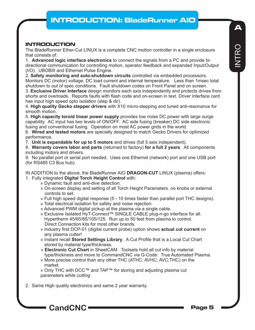
INTRODUCTIONThe BladeRunner Ether-Cut LINUX is a complete CNC motion controller in a single enclosure that consists of:1. Advanced logic interface electronics to connect the signals from a PC and provide bi-directional communication for controlling motion, operator feedback and expanded Input/Output (I/O). UBOBIII and Ethernet Pulse Engine.2. Safety monitoring and auto-shutdown circuits controlled via embedded processors. Monitors DC (motor) voltage, DC load current and internal temperature. Less than 1msec total shutdown to out of spec conditions. Fault shutdown codes on Front Panel and on screen.3. Exclusive Driver Interface design monitors each axis independently and protects drives from shorts and overloads. Reports faults with flash code and on-screen in text. Driver interface card has input high speed opto isolation (step & dir).4. High quality Gecko stepper drivers with X10 micro-stepping and tuned anti-resonance for smooth motion.5. High capacity toroid linear power supply provides low noise DC power with large surge capability. AC input has two levels of ON/OFF. AC side fusing (breaker) DC side electronic fusing and conventional fusing. Operation on most AC power grids in the world. 6. Wired and tested motors are specially designed to match Gecko Drivers for optimized performance.7. Unit is expandable for up to 5 motors and drives (full 5 axis independent). 8. Warranty covers labor and parts (returned to factory) for a full 2 years. All components including motors and drivers.9. No parallel port or serial port needed. Uses one Ethernet (network) port and one USB port (for RS485 C3 Bus hub).
IN ADDITION to the above, the BladeRunner AIO DRAGON-CUT LINUX (plasma) offers:1. Fully integrated Digital Torch Height Control with: » Dynamic fault and anti-dive detection. » On-screen display and setting of all Torch Height Parameters. no knobs or external controls to set. » Full high speed digital response (5 - 10 times faster than parallel port THC designs). » Total electrical isolation for safety and noise rejection. » Advanced PWM digital pickup at the plasma via a single cable. » Exclusive Isolated HyT-Connect™ SINGLE CABLE plug-n-go interface for all. Hypertherm 45/65/85/105/125. Run up to 50 feet from plasma to control. Direct Connection kits for most other brands. » Industry first DCP-01 (digital current probe) option shows actual cut current on any plasma cutter! » Instant recall Stored Settings Library. A Cut Profile that is a Local Cut Chart stored by material type/thickness. » Electronic Cut Chart in SheetCAM. Toolsets hold all cut info by material type/thickness and move to CommandCNC via G-Code: True Automated Plasma. » More precise control than any other THC (ATHC; AVHC; AVC;THC) on the market. » Only THC with DCC™ and TAP™ for storing and adjusting plasma cut parameters while cutting
2. Same High quality electronics and same 2 year warranty.
Familiarize yourself with the controls on the BladeRunner Front Panel and with the loading and operation of CommandCNC with the proper profile. After you have the PC installed and the cables and satellite cards hooked up, you will be guided through a series of tests to determine if everything is working. We ask that you go through the setup and manual in the order presented. If at some point you cannot get the expected results and check your connections and setup with no success, then call our tech support person at 903-364-2740 during normal business hours (posted on the CandCNC website). Often an email to will get a response after hours or on [email protected]. Another valuable source of help is the CandCNCSupport Group at http://www.candcnc.net/supportforumYou must have a yahoo membership and you must request to join the CandCNC forum. The Group is open to all persons interested in CNC cutting and/or CandCNC products.
Installation and setup of your BladeRunner AIO ETHERCUT for LINUX....OVERVIEW.
There are a series of steps you should complete to setup and interface the BladeRunner EtherCut AIO with your PC.
1. Install any CommandCNC updates (check website).
2. Connect PC to BladeRunner (MP3600) and USB 4 Port Hub.
3. Connect motors (on test bench or table).
4. Apply power to BladeRunner ESPII-A unit (Main Power cord).
5. Run a quick series of tests to confirm the motors are working and that CommandCNC is running in the default settings.
7. Run menu driven Configurator program from the LINUX Desktop to load and configure the hardware and software for different profiles.
11. Tune and Calibrate the motors on each axis. Check for proper motion.
12. Setup and Test Inputs and Outputs for Homes and Limits.
13. Proceed to the DTHC IV Setup & Config Manual.
INT
RO
INTRODUCTION: BladeRunner AIO
PreConfigured PC’s from CandCNC already have default Profiles
The axis and motors will be setup and the standard inputs defined.
The motor tuning will have to be changed to match a specific
mechanical configuration.
This manual is for the setup and initial testing of the BladeRunner AIO EtherCut and the PC running CommandCNC. It DOES NOT cover the setup and testing of the DTHC, or any other Options. It provides the setup to get correct motion and check inputs and outputs. It does not teach you how
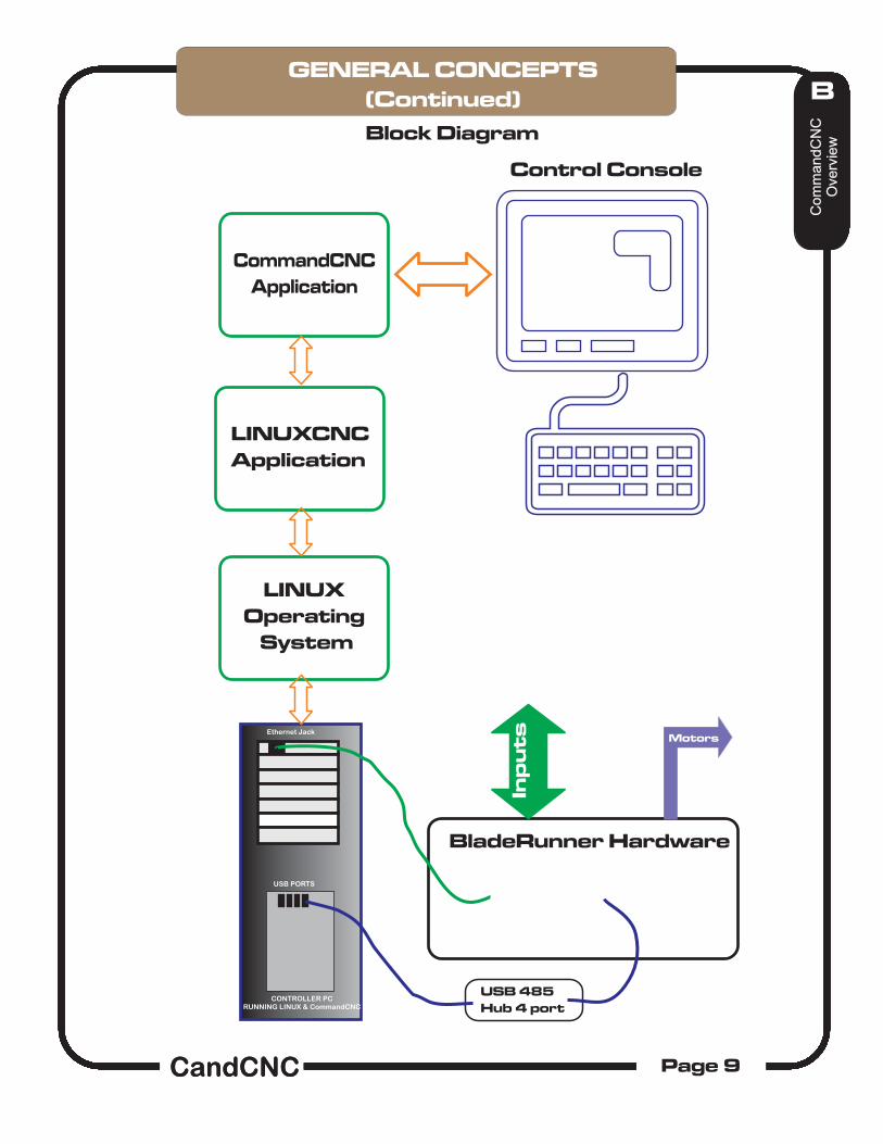
It helps to have a basic understanding of how CommandCNC (CCNC) operates, what it does and how it combines with the BladeRunner Hardware to generate motion.
There are 3 distinct parts (legs) of CNC: CAD (Drawing), CAM (Toolpathing) and CONTROL (operation of the hardware and operator interface). LINUXCNC/CommandCNC is the third and last (CONTROL). It does not generate toolpaths from a file; it cannot be used to draw or edit artwork. It runs a specific “dialect” of G-Code.
Specific software programs are used for the CAD (drawing) to generate the base artwork in vector format. For simple shapes a pure CAD program can be used. For artistic, decorative or signage type cuts, a drawing program that allows drawing in vector format (lines) will better fit the needs and is a lot faster than pure CAD. It will allow import of several Vector type formats to allow you to use vector clipart (like the files found at www.VectorArt.com) The two most popular (Windows ) drawing programs are CorelDraw (any version after 11) and Adobe Illustrator. A FREE alternative is Inkscape and runs in Windows or LINUX, and is included on our Support CD. You can also download it from http://inkscape.org/download/?lang=en The CAM process takes a drawing file and allows the user to import it in line format, define the objects to cut, in what order, with which tool, and what type of cut. Better CAM programs have automatic lead-ins/outs (essential for plasma) and cut type settings. The most essential piece is the “POST” processor that translates the CAM programs native toolpath data to standard G-Code in a form that matches your control program (CommandCNC). The best value and most flexible CAM for 2-D or 2.5-D cutting is SheetCAM. It is available at www.SheetCAM.com. SheetCAM TNG is a part of our Software Options. We include custom POST files that add the advanced automaton features in the DTHCIV. You will not have access to those features if you elect to use another CAM program or a drawing program with a built-in CAM option. While some CAM programs offer a way to modify their POST the POST language in SheetCAM is a programming language (LUA) and can do internal math functions and work interactively with SheetCAM. We strongly suggest you use SheetCAM with CommandCNC for plasma cutting.
Some programs combine CAD and CAM or CAM and CONTROL but they typically are a compromise and one or more sections will not be as robust as the other. To maintain maximum flexibility and not be placed in a position where you have to change out an expensive tool (or quit using a section), it is recommended you run separate applications for each “leg” of the CNC Triad. You can then pick and choose the features from each one that best suits the type cutting you do.
CommandCNC uses setup “Profiles” (Configs) stored in the ../linuxcnc/configs/ <config file name> as multiple files. It stores all of the settings about the hardware and interface (input pins, output signals and pins) motor tuning and travel directions. We use a term called “mapping”. It refers to defining a specific function to a specific port and pin setting in CommandCNC. There is a GUI CONFIGURATOR application that lets you edit or create new CONFIGS. Certain settings that are specific to your machine (motor tuning, travel directions, etc.) have to be entered during setup. The settings get stored in the current running PROFILE. Be careful modifying a working profile. Make a clone of it and do you modifications.
The screen presentation for the BladeRunner is in the form of a custom screen “objects” (GTK + objects). The screen development tool named GLADE is used to place and define the objects. The file is stored in the ..linuxcnc/configs/<your config>/ Folder. It controls what buttons, readouts (DRO’s) and bitmaps (pictures) are on the screen, and in a sub-folder named CandCNC. With the exception of certain custom objects in a screen there is no setup information. Certain operations on the BladeRunner (parameter feedback and DTHC or Spindle Speed functions) MUST use the associated screen set to operate properly.
The G-code runs in CommandCNC and gives it moves in absolute (measured from a beginning zero point) XY and Z coordinates. It’s up to LINUXCNC to process the file, do the math and based on the settings in the Profile, issue the proper number of pulses (steps) and proper direction (dir) to the motor drive modules (hardware). There is no positional feedback between LINUXCNC (software) and the table position (hardware). CommandCNC is not “closed loop”. It issues the signals at the rate set by the motor tuning rules and it’s up to the hardware to move to that location.
CommandCNC reads the INPUTS from external sensors (switches) and links those inputs to a function in LINUXCNC. It also handles OUTPUTS to turn ON/OFF a specific device hooked to the CommandCNC hardware (BladeRunner/Plazpak/ MP3600 etc.).
C3 Bus RS485 4 Port Hub The C3 bus is an exclusive communications bus used with CommandCNC that provides a “backside” lower speed method for CommandCNC to talk to the hardware. It uses a single USB port (because most PC’s have one) and converts it to a highly noise immune serial communications port(s). While it's a lot slower than USB its is extremely reliable over long distances and has been an industrial standard for many years for reliable communicators. CandCNC has a series of modules that plug to the C3 Bus RS485. Most notable is the DTHCIV and while the actual operation in real time of the DTHCIV is local and very fast, the C3 Bus is used to do things like load new settings in to the memory of the DTHCIV and to send back screen information to CommandCNC like the Torch Volts and status indicators.
LINUX CNC DESKTOP USER INTERFACE’LINUX CNC DESKTOP USER INTERFACE’
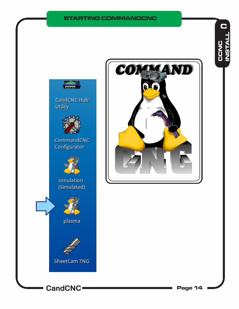
APPLICATIONS MENU
HUB ADMIN (UTILITY). Opens Hub Admin application to setup and test RS485 connected 4 port hub and all attached devices. Run with CommandCNC not loaded.
COMMANDCNC CONFIGURATOR. Create and Edit COMMANDCNC Profiles (config files).
COMMANDCNC CONFIG Simulated profile allows running CommandCNC in DEMO mode with no hardware attached. Will not actually cause motion or read external inputs.
COMMANDCNC CONFIG Plasma profile allows running CommandCNC using the default Plasma Profile. You can clone another profile from it or use and edit the settings. Cloned Profiles do not put an Icon on the desktop
SHEETCAM TNG. SheetCAM TNG application for LINUX. It may be a DEMO version (unlicensed) unless a license was purchased with the system. If you want to use it on the LINUX system without limitations and have a Windows License, it can be transferred to the LINUX computer
CommandCNC updates will generally be available as .deb or zip packages, which
will be named something like this: commandcnc_setup_0.5_1386.run
The CommandCNC package version is in the file name: the one shown above is version 0.5.0.You can save them in your /home/<user>/Downloads directory, and then open the file manager and browse to that directory. Double-click the file and it will open in a program that will have an install button on the right side. Click the button to install.
Note: you might get a message box telling you that, “The package is of bad quality”.
You can safely click “Ignore and install” to continue the installation.
Next you may be asked to “Authenticate” - simply enter your login password to continue.
CC
NC
Up
da
tin
g
CUPDATING COMMANDCNC
The default system password on CandCNC PC’s is “plasma” If you change thepassword write it down because we cannot recover a lost system (root) passwordand you will not be able to do updates!
Larger updates may be distributed as a combined setup package named something
like this: commandcnc_setup_0.5._i386.run.zipTo install this kind, save the file onto your computer – We recommend putting it in your Downloads directory. Then open the file manager (Home icon on the desktop) and find the file, then extract the installer by right-clicking on the file and selecting “Extract Here.”
Then double-click the commandcnc_setup_*.*.*.run file to start the installation. Enter your password when prompted and when it is finished you can close the window and go to the next step.
CC
NC
Up
da
tin
g
CUPDATING COMMANDCNC
The default system password on CandCNC PC’s is “plasma.” If you change thepassword write it down because we cannot recover a lost system (root) passwordand you will not be able to do updates!
• Ethernet card firmware updates now in configurator
• Allow floating point Z steps-per-unit
CommandCNC 0.5
• Improved support for Router screen and setup
• Sheetcam post rev 14 with scriber fixes
• Added Sheetcam tools for CommandCNC
CommandCNC 0.4
• Improved support for 5 axis systems
• Added support for 6-motor systems
• Handles axes with no home switch properly now
• Added support for auto-squaring with two home switches on a gantry
Note:
To use two home switches on a gantry, set two inputs to the same axishome switch. So for a Y gantry, you could set “Y home input” = “Y Home switch”, and “A home input” = “Y Home switch”
CommandCNC 0.3.9
• Fixed Z synchronization problem for cuts with DTHC OFF
CommandCNC 0.3.8 (since 0.3.3)
• Dry run support - motion should not hold for ARC OK when THC is off now.
• Step polarity settings
• Settings to stop probe errors when homing and jogging
• Torch Disable check box - good for dry run and for resuming a cut.
BLADERUNNER AIO RIGHT SIDE VIEW INPUTS FOR UBOB III AND EXPANSION OPTIONS
Connecting up the BladeRunner Control box. Take a look at the block diagram on the next page that gives an overview of the control box. Note that there are two cables that run from the PC and connect to the BladeRunner box. One is the (BLUE) Cat 5 from the C2Bus 4 Port Hub (not rewired on ROUTER version) The other is the Ethernet CAT 5 (GREEN) and it is REQUIRED on all EtherCut systems
1. Install a Green CAT 5 drop cable (All pins straight through) between Ethernet (network) Port on the PC to the part marked Ethernet on the side of the BladeRunner controller unit.
2. You should have the C3BUS USB to RS485 installed and working and the cable should be connected (BLUE CAT5)
Note: all of the CAT 5 cables are the same pinout. We have designated and provided cables in the colors indicated to help prevent plugging in the wrong device to the BladeRunner. Getting the wrong device plugged in, and the unit powered up, can result in possible damage to the module or the PORT on the C3BUS hub or the PC. BE CAREFUL!
Green Cat5 from Ethernet Jack on EtherCut front panel TO Ethernet jack on PC. Up to 25ft length.
USB PORTS
BLUE CAT5 cable for
RS485 from C3BUS Jack on
Ether-Cut to
Ethernet Jack
To PWM Module
CandCNC C3BUS RS485 4 Port Hub
CONTROLLER PCRUNNING MACH3
UP
TO
25
ft
UP
TO
25
ft
UP
TO
25
ft
6 ft or less
CAUTION: All cables are CAT5UTP 8 conductor and will plug intoany CAT 5 (RJ45) jack. We have colorcoded the cables to help keep them from being mis-connected. If you use other CAT cables be sure to labelthem on each end. Connecting cableswrong could damage modules.
It is important that the stepper motor wires are wired correctly. When shipped from the factory the motors are wired right and each one is tested with the unit. Because motors for other products we sell are wired differently it’s possible a motor you order after the unit has been shipped could be wired differently. DO NOT ASSUME THAT THE COLOR OF THE WIRES IS CONSISTENT. We order wire from different sources and cannot always define the wire colors. If you take the connectors off for any reason, either mark the wires by position or use an ohmmeter to test for coil pairs (see next page). If you use any other motor or rewire for any reason, CHECK TO MAKE SURE THE COILS ARE NOT CROSSED.
1
!
COLOR CODE MAY VARY
Screw TerminalsFace UP
NOTE: For BladeRunner Servo system please see the end of the F section for the differences in the motor connections.
It is important that the stepper motor wires are wired correctly. When shipped from the factory the motors are wired right and each one is tested with the unit. Because motors for other products we sell are wired differently it’s possible a motor you order after the unit has been shipped could be wired differently. DO NOT ASSUME THAT THE COLOR OF THE WIRES IS CONSISTENT. We order wire from different sources and cannot always define the wire colors. If you take the connectors off for any reason, either mark the wires by position or use an ohmmeter to test for coil pairs (see below). If you use any other motor or rewire for any reason, CHECK TO MAKE SURE THE CONNECTIONS ARE CORRECT USING THE METHOD BELOW.
NOTES: Aux Power uses separate cord and connects ONLY to the AUX outlets. Outlets are rated at 250V AC max. Circuit will switch AC or DC volts. Uses Aux Relays located on the Table I/O card. Inlet socket supplies BOTH outlets. Not tied to internal AC circuits .
Units setup for 220VAC will have the same inlet (IEC) sockets. Aux power can be wired for 220 VAC.
Main Unit draws under 600W at full load (5 motors full load)
Connections on UBOB III REV 16 to MESA Ethernet Card
Other standard connections not shown
U B O B I I I R E V 1 5 P o r t s & P i n s f o r E S S s e t u pI n p u t sS i g n a lP O R T - P I NO L D S I G N A LX H O M E1 - 1 11 4X H O M EX H O M EY H O M E1 - 1 21 5Y H O M EY H O M EZ H O M E1 - 1 31 6Z H O M EZ H O M EA H O M E1 - 1 51 7A H O M EA H O M EB H O M E2 - 42 1B H O M ET H C U PC H O M E2 - 52 4T H C D O W NI N P U T 1 ( H O L D )2 - 32C H O M EA R C O KL I M I T S2 - 21L I M I T SL I M I T SE S T O P1 - 1 02 0E P OE P OA U X 12 - 1 52 3N CA U X 2A U X 3A U X 4A U X 5A U X 6O U T P U T SS i g n a lP O R T - P I NX S T E P1 - 2A x i s I O - 2X D I R1 - 3A x i s I O - 3Y S T E P1 - 4A x i s I O - 4Y D I R1 - 5A x i s I O - 5Z S T E P1 - 6A x i s I O - 6Z D I R1 - 7A x i s I O - 7A S T E P1 - 8A x i s I O - 8A D I R1 - 9A x i s I O - 9B S T E P2 - 1 4A x i s I O - 1 8B D I R2 - 1 6A x i s I O - 1 9C S T E P2 - 1A x i s I O - 2 4C D I R2 - 1 7A x i s I O - 2 5O U T 1 = T O R C H R E L A Y1 - 1 4N AO U T 2 1 - 11 0K 4 R E L A YO U T 31 - 1 61 1K 3 R E L A YC h a r g e P u m p1 - 1 72 5 P i n C O N T A B L E I / OT A B L E - I O N A M E2 5 P i n C O N A X I S I / O
Located on the Front Cover of the ESPII Enclosure, the FRONT PANEL is the Operator Interface for the ESPII and provides tactile pushbuttons to turn the DC power to the Motors ON/OFF. The FRONT PANEL is a SMART CONTROL utilizing a powerful microprocessor that monitors and controls the power section of the BladeRunner AIO. The ESPII monitors critical parameters, controls ON/OFF, and will automatically shutdown in microseconds in the event of a fault. The ESPII monitors/controls: 1. System DC status 2, System Driver Status (enable/disable drives) 3. DC voltage level (overvoltage shutdown) 4. DC current (load) level (overload shutdown) 5. Internal Temperature (overtemp shutdown) 6. System Fault Indicators (LED’s and Screen Text)
E
BladeRunner HardwarePOWER CONTROL
MOTOR POWERMOTOR POWER
ON OFF
ON OFFSTANDBY
CandCNCESP II-A
Enhanced Smart Power
DRIVESOFF
POWERFAULT
TEMPFAULT
LOADDUMP
DRIVEFAULT
CandCNCMulti-Axis Controller
C3BUS
Normal Power up sequence:1. Operator turns on MAIN POWER SWITCH. +5VDC LED comes on; RED OFF LED comes on; DRIVES OFF LED comes on. All LEDS may sequence on once during processor turn on.2. Operator pushes ON Button. ON LED turns Green OFF LED goes off. Power comes up on DC bus. Approx 2 sec later Drives OFF LED goes off and MOTORS LOCK.
BLADERUNNER AIO FRONT PANEL[Enhanced System Power II-A]
IMPORTANT INFORMATION: The ESPII provides multiple levels of
protection for the system and the motor drivers. Electronic fusing will shutdown power in milliseconds as opposed to
conventional fuses. The Primary AC has two levels of control. The MAIN POWER
SWITCH and the in-line SAFETY RELAY (controlled by the FRONT PANEL). The Safety RELAY controls AC
power to the DC power supply section. Besides
Electronic fusing the system also provides failsafe
conventional fuses/breakers. There are two levels of
conventional fusing on the DC power side. The
locations and values of the conventional fuses are in the
8. Jog the axis in turn using the keyboard Jog keys a. Left and Right Arrow --> and <-- should jog X axis b. Up and Down Arrow should jog Y axis c. PageUP and PageDown should Jog Z axis9. STOP! If you cannot get an axis to move or if it only moves in one direction: a. Check to make sure the associated DRO is changing on the screen b. If it is, then check all of your cables from the PC to the Control box c. Contact Tech Support or post on the Support Forum10. If you have motion on all attached motors then proceed to the next section
XY JOG KEYSENTER KEY
Q W E R T Y U I O P
A S D F G H J K L
Z X C V B N M
NumLock
7
4
1
/
8
5
2
*
9
6
3
0
-
+
ScrollLock
PrintScrnSysRq
Pause
BreakF1 F2 F3 F4 F5 F6 F7 F8 F9 F10 F11 F12Esc
Home
EndPageDown
PageUpInsert
Delete
Enter
1 2 3 4 5 6 7 8 9 0
CtrlCtrl Alt
* ( )$ % ^ &! @ #
Shift Shift
`
~
Tab
CapsLock
-
_
=
+
\
|
[
{
]
}
;
:
'
"
/
?
.
>
,
<End
Home p PgU
PgDn
Del
.
Ins
NumLock
CapsLock
ScrollLock
Alt Gr
Z JOG KEYS
A Axis JOG(if defined)DEFAULT HOTKEYS (BladeRunner Profiles)
AXIS DRO’s
BladeRunner HardwareMotion Check
INITIAL MOTION CHECK: After you have powered up the BladeRunner and checked the power on sequence and checked the motors on each axis, the next step is to plugin all motors and run an initial motion check. You can wait to do this after you get the motors mounted on your CNC table if you want, or you can set the motors on the table oriented like they will be mounted to check initial motion and direction.
1. Make sure the PC connections have been made and the PC Hardware ports setup as per previous sections. 2. Plug in all the motors. Orient them like they are going to be mounted. Label them if they are not on the table.3. Turn on the main power switch on the end of the BladeRunner ESPII box.4. Turn on Motor DC using the Front Panel ON (Green ) button.5. Check to make sure the motors “lock” and that you have a Green ON LED6. Start CommandCNC with the plasma or router profile (desktop Icon).7. Bring CommandCNC out of RESET so the E-STOP button shows “PRESS for E-STOP” and is dim
Universal AC Power Plug100VAC to 240VAC 50/60HZRegulated 5V @ 1A out
ACTIVITY MONITOR LEDS
When a device is plugged into a port on the hub, the LED will light if it has proper communications. It does not mean the device is operating correctly (see later
pages for using the Hub Utility). The Activity Monitor shows send and receive activity on the port
Standard CAT5 UTP up to 50ft
USB ACT LED showsvalid connection to PCon USB channel
The USB Active (ACT) LED only comes on when there is a valid USB connection to the PC. Drivers have to be loaded and active.
INSTALLING CandCNC RS485 Devices to the USB-RS485 4 PORT HUB
The USB-RS485 4 PORT HUB has an advanced processor that can communicate with several RS485 devices. RS485 is a robust and noise-immune communications standard used in industrial electronics for years. Because of its differential signal methods, it is unaffected by external or ground based noise and reliable communications of several hundred feet are common. RS485 is a multi-drop topology meaning there can be multiple devices on the same pair of wires as long as all of the devices operate at the same speed (BAUD RATE) and have a unique address. Since USB is a common port on most PC’s it is a logical choice for communications that do not depend on precise timing.
You will note that the USB-RS485 4 Port Hub has four independent channels and each channel can talk to multiple devices. Because of different Baud Rates or special signals the 4 port hub has two special jacks:
1. Hypertherm RS485 Port. This channel runs at a much slower speed and can only talk to a Hypertherm Plasma Cutter equipped with an RS485 port (optional) and through our HyT-Connect RS485 interface. If you already have the HyT-Connect RS485 SIM Kit installed and have the older single port (dual jacks) RS485 module you need to unplug the existing setup and plug the RJ45 (Cat5) cable FROM the port on the rear of the Hypertherm into the jack 1 marked “To Hypertherm Rs485 PORT.
USB- RS485 4 PORT HUBPlug Locations and Layout
INSTALLING RS485 4 PORT HUBRS485 4 PORT HUB - DEVICE CONNECT
During the install the CandCNC Hub Utility was added and an ICON was placed on your desktop.Click on the icon to open the Hub Utility.
2. PN200 Hand Control. The PN200 hand control uses normal high speed baud rates but the special “dead man” E-Stop to the EPO of any CandCNC controller requires a special jack. The PN200 MUST be plugged into the PN200 jack to be able to use the E-STOP safety (recommended). The PN200 has to be the last device in a group of devices. The PN200 will work plugged into other jacks on the 4 PORT HUB (except JACK 1) but you cannot use the E-STOP option. You can also use the PN200 jack on the hub for other RS485 devices if you do not have a PN200. While the PN200 would work with other devices on the channel that have loop through (pass through) jacks the E-STOP to EPO DOES NOT PASS THROUGH OTHER DEVICES.
3. DTHC IV High Speed Digital Torch Height Control. The DTHC IV uses the RS485 (C3BUS) for the following:
Transfer of screen information to CommandCNC like Torch Volts, Torch Amps and the status LED’s for Torch UP, Torch DOWN and ARC OKAY. Unlike the DTHC II that uses defined parallel port inputs for the UP, DOWN and ARC OK, the DTHC IV sends the data across the RS485. The only “hard” input from the DTHC IV to CommandCNC is the HOLD signal (mapped to INPUT 1 on Ports & Pins). Communication to the plug-in in CommandCNC to update Z position when DTHC is active (tells CommandCNC where the DTHC has moved the Z while under THC mode). Pass parameters and settings in MACH to the memory of the DTHC IV. This includes all of the DTHC Cut Profile Settings either from the screen or from the G-code when using DCC.
MANAGING THE HUB
The following screens show the CandCNC Hub Utility displaying information about different devices connected to it. The Hub is “smart” and automatically detects any compatible device connected to it. Review the screens that follow and understand what each section of the screen is used for.
IMPORTANT: The purpose of the HUB UTILITY is primarily to confirm proper communication with each device and to be able to do some base level testing . You cannot run the Hub Utility at the same time MACH is running.
Shows a list of connected devices. As a device is connected and sensed by the hub it will appear in the list. If you connect a device and it does not show up immediately, stop (close) the application and restart.
DEVICE DETAILS
Provides the:Device NameDevice Code: Each CLASS (type) of device has a different Device CODE. Codes can be from 1 to 99.Device Address: The unique address of a device within a class (values from 1 to 8). Devices of the same type must have a different Device Address. Future cards will have address jumpers to allow multiple cards of the same type to work on the same hub.Firmware Version: This displays the current
Hub Connected (to USB on PC) Displays current firmware of the HUB. This MUST show connected status before any other of the functions will display.
TEST DEVICEAction button that opens a new dialog window. You must have a device highlighted in the Devices List to use the Setup/Test Device
Update Device FirmwareThis allows you to update each module with new firmware. New firmware will be designated by a REV number. Firmware updates will be available for down load in a special download section of the CandCNC website and on the Yahoo CandCNCSupport Forum.
C3 HUB MANAGEMENT
HUB UTILITY
The Hub Utility is an application provided to manage the C3BUS USB to RS4854 Port Hub and the devices attached to it. With the utility you can:
Update the Hub Firmware (Firmware is the program that runs the hub)Update Firmware in the Devices attached (like the DTHC IV)Test basic communicationsTest device functionsDevice level diagnosticsSet some device settings
What you CANNOT DO:Run CommandCNC (Both applications trying to talk to the same device does not work).
USB- RS485 4 PORT HUBINSTALLING RS485 4 PORT HUBUSING HUB UTILITY Application
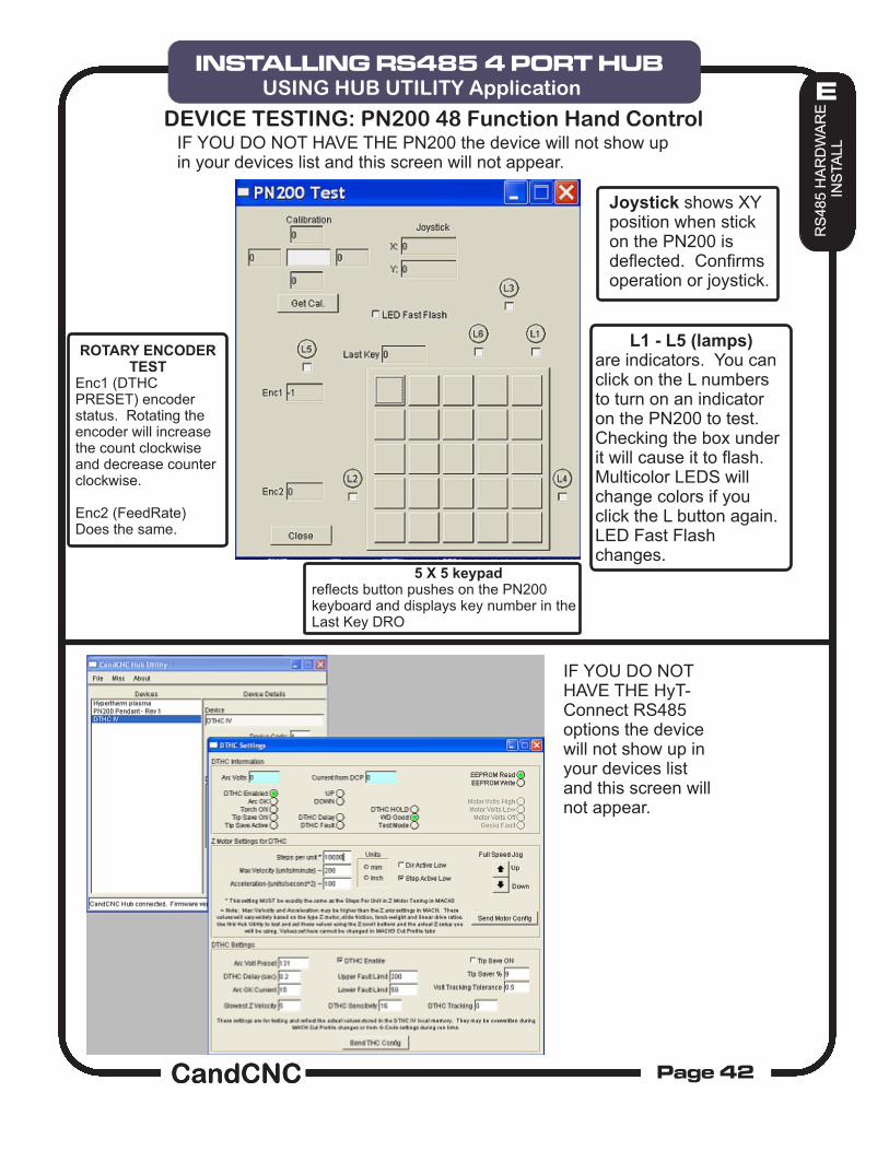
DTHC INFORMATION is direct feedback from the DTHC IV module and indicates the current status of the unit . You cannot make changes or do inputs from this section. Since you cannot run MACH and the Hub Utility at the same time, these settings are primarily used for off-line diagnostics at the factory.
Z MOTOR SETTINGS. This section is the most important because it sets the base motor settings for the Z motor under DTHC control. You will find that the Max Velocity and Acceleration will be much higher than your settings in MACH for the Z motor tuning. This is normal because of the DTHC IV controlling the motion directly under THC. You should set this as high as possible. Move the settings up and test the Z motion using the Full Speed Jog buttons on the screen. The motor should move smoothly and rapidly both up and down. Lose steps (or faults on a servo system) back the numbers off by 25%. The settings here are for a stepper system with a 620 oz-in motor running a 5 TPI leadscrew. Your settings will vary but you should be able to hit about double the velocity and acceleration of the Z motor tuning in MACH. IT IS IMPORTANT THAT THESE SETTINGS BE OPTIMIZED for best response under DTHC control. They will effect the Gain and Tracking settings for the DTHC.
THIS IS THE ONLY PLACE TO SET THE Z TUNING FOR DTHC IV . A MINIMUM INSTALL REQUIRES YOU PREFORM THIS ONE FUNCTION IN THE HUB UTILITY.
DTHC SETTINGS. These settings are covered in the DTHC IV Setup and config Manual.
IMPORTANT!!! This section covers some setup and testing of the DTHCIV module. While the DTHC IV Setup and Config Manual should be used to do the actual DTHC IV part of the install you should do the minimum tuning listed to setup the Z motion.
C3 HUB MANAGEMENT
HUB UTILITY
USB- RS485 4 PORT HUBINSTALLING RS485 4 PORT HUBUSING HUB UTILITY Application
Joystick shows XY position when stick on the PN200 is deflected. Confirms operation or joystick.
L1 - L5 (lamps) are indicators. You can click on the L numbers to turn on an indicator on the PN200 to test. Checking the box under it will cause it to flash. Multicolor LEDS will change colors if you click the L button again. LED Fast Flash changes.
5 X 5 keypad reflects button pushes on the PN200 keyboard and displays key number in the Last Key DRO
ROTARY ENCODER TEST
Enc1 (DTHC PRESET) encoder status. Rotating the encoder will increase the count clockwise and decrease counter clockwise.
Enc2 (FeedRate) Does the same.
DEVICE TESTING: PN200 48 Function Hand ControlIF YOU DO NOT HAVE THE PN200 the device will not show up in your devices list and this screen will not appear.
IF YOU DO NOT HAVE THE HyT-Connect RS485 options the device will not show up in your devices list and this screen will not appear.
HUB MANAGMENT
HUB UTILITYC3 HUB MANAGEMENT
HUB UTILITY
USB- RS485 4 PORT HUBINSTALLING RS485 4 PORT HUBUSING HUB UTILITY Application
After you have installed MACH and run the BladeRunner INSTALL on the Support CD, open MACH3 using either the MACH Loader and the BladeRunner selection from the list OR using the BladeRunner Icon created in the desktop.
You should see the following screen or something very close. If you are missing the Desktop icon or it’s not in the selection list, re-run the INSTALL again. If you have the Profile (BladeRunner) listed in the MACH LOADER and the screen does not display, go to the top menu bar and select VIEW/Load Screens and navigate to the MACH3 folder and select BladeRunner-Router.set. If it is missing any of the Bitmaps (picture buttons and/or backgrounds) then confirm the Installer created the CandCNC folder under the MACH3/Bitmaps Folder and there are files in that folder. We have included a Zip file on the CD of all the bitmaps and the ZIP file is on the CandCNCSupport Forum site in the FILES/BladeRunner Support Files Folder. You can UNZIP the files in the Bitmaps.ZIP file directly to the MACH3/Bitmaps/CandCNC folder. Along with bitmaps and other features the BladeRunner screens contain several custom functions embedded as code behind certain buttons. If you elect to use another screen SET file with the BladeRunner be aware some functions will not work. The DTHC screens have specific functions and the DTHC functions will not work on other screen sets.
Machine is in E-STOP. No other buttons will respond until its out of E_STOP. External events (E-Stop input goes active) can cause E-STOP of hitting the button stops all motion and puts machine in e-stop.
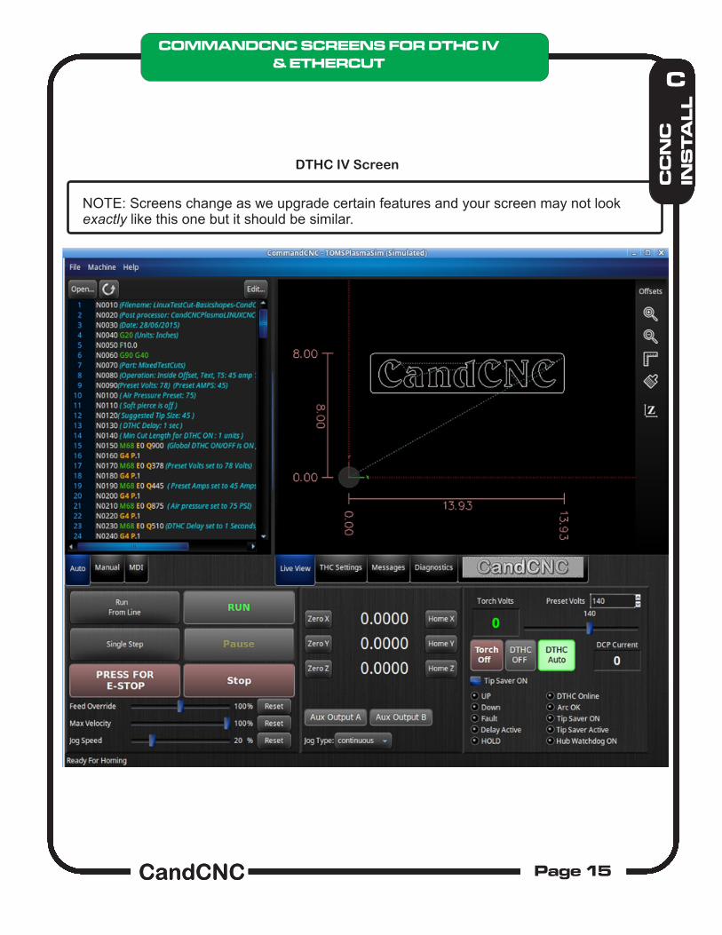
Indicates E-STOP is NOT active .
Clicking PAUSE while code is running stops motion (FEEDHOLD) and clicking Resume starts from the spot of the PAUSE/ Clicking STOP stops the code (not the same as E-STOP).
If code is loaded clicking RUN turns RUN Button GREEN and starts code
Feed Override. Increase or decrease the runnng feedrate by the precentage slected. Use this control carefully. Pushing the speeds too high whiel cutting can have other effects that can cause toolpath deviations. Max Velocity. This sets the speed the machine runs when doing rapids (G0 moves) 100% is whatever the velocity in Motor tuning is set to. Lowering Max Velocity slows down rapids (and possibly G1/G2/G3 moves if it is less than the feedrate in the G-Code) Jog Speed si the speed you jog the machine using the keyboard jog keys. Message box. Gives system status messages .
Feedrate: Shows actual (blended ) feedrate. Zero [XYZ] Buttons Resets the DRO for the associated Axis. This sets the WORK ZERO . It does NOT change the Table Zeros (HOME). Home [XYZ] Buttons Moves the axis to the associated HOME position and zeros the machine to Table home. All other postions are OFFSETS from Table Home. In Simulation mode the buttons simply Zero the Table position. Axis Output A & B. These turn on/off the two auxiliary AC outlets (A & B) on the BladeRunner. (relays on the MP3600 table I/O card) They can be triggered by G-Code using M7 and M8 for on and M9 for off Jog Type
Axis Output A & B. These turn on/off the two auxiliary AC outlets (A & B) on the BladeRunner. (relays on the MP3600 table I/O card) They can be triggered by G-Code using M7 and M8 for on and M9 for off.
Jog Type: Continuous or Incremental. When you click the control you have a choice of continuous or a list of different increments (steps). In Continuous mode the axis moves as long as you hold the axis jog key/button down. In any of the Incremental selections the axis moves that amount and stops. Releasing and striking the jog key again moves it just that amount.
The MANUAL button in the upper left frame opens a set of manual sub routines that perform specific manual actions.
The LOAD MATERIAL button moves the XYZ to a preset position defined by the values entered into the XY and Z Input boxes. The values are stored and only need to be entered once and can be changed if needed. After the values have been set you can push the Load Material button and it will manually move the three axis to that position. NOTE: You have to be out of RESET before you can enter values or activate the button.
The Z Touch-off button is a special function sub routine that moves the Z down until the probe input is activated then lifts the Z the amount to cancel the switch offset. It then zeros the Z. THIS IS DIFFERENT than a homing move on Z since homing just moves to the switch and stops. Homing does not apply the offset or lift the Z to the new zero. The Z Switch Offset is entered into the Z motor tuning as the Home Switch Offset.
OVERVIEWYou do motor tuning for Z using the CommandCNC Configurator .
When used with the CommandCNC POST for SheetCAM you can set a POST option to use the Z Touch-Off sub routine in code INSTEAD of using the SwitchOffset in SheetCAM. See the section in PART 2 on setting up the POST Options.
MDI screen lets you type one or multiples lines of G-Code and execute.
G-code display uses key word color highlight Toolpath zoom with mouse or from menu
Load your G-Code generated by the CommandCNCLinux Post and see the toolpath.Take the system out of RESET and RUN the code and watch it simulate the cut. You can enlarge or shrink the toolpath display independent of the screen and add or remove the rulers using the right-side menu bar.
Context highlighting on the G-Code scroll lets you better read and understand what it is doing.
You can use the MDI screen to write and run code interactively to do a quick cut or to troubleshoot.
NOTE: Important feature allows you to scroll and highlight a line of G-code and that cut will show up on the toolpath in the Toolpath Display. Conversely you can highlight a cut on the Toolpath and it will take you to the line of G-Code in the G-Code display.
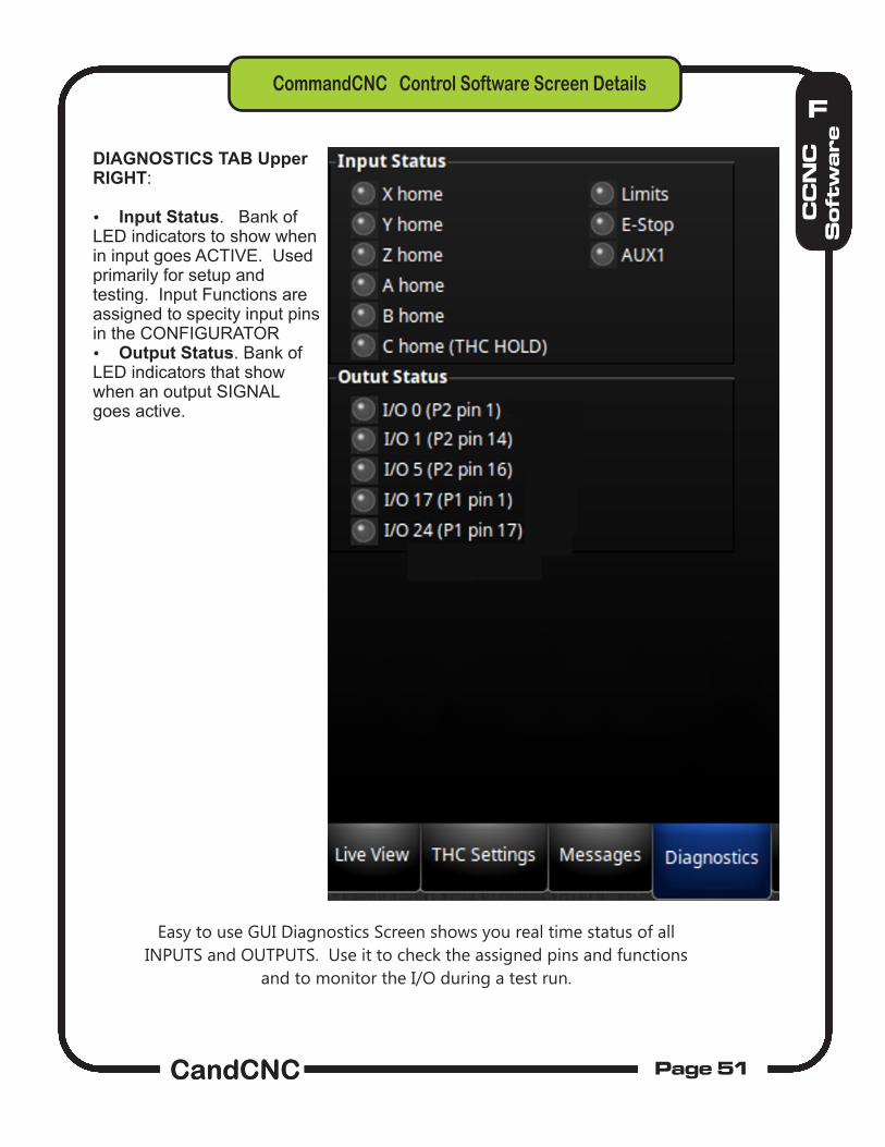
Easy to use GUI Diagnostics Screen shows you real time status of all
INPUTS and OUTPUTS. Use it to check the assigned pins and functions
and to monitor the I/O during a test run.
DIAGNOSTICS TAB Upper RIGHT:
Input Status. Bank of LED indicators to show when in input goes ACTIVE. Used primarily for setup and testing. Input Functions are assigned to specity input pins in the CONFIGURATOR Output Status. Bank of LED indicators that show when an output SIGNAL goes active.
The AXIS Tab allows you to define the Maximum Velocity , Acceleration and Soft Limits of each
ENABLED axis. This is not the “Calibration” which defines the number of steps it takes to travel
one “Unit” (inch or millimeter) and is done in the Motors Tab (see next page).
G
CC
NC
Co
nfi
gu
ra
to
r
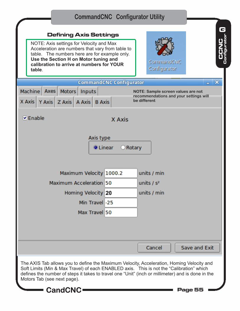
Defining Axis Settings
NOTE: Axis settings for Velocity and Max Acceleration are numbers that vary from table to table. The numbers here are for example only. Use the Section H on Motor tuning and calibration to arrive at numbers for YOUR table.
The AXIS Tab allows you to define the Maximum Velocity, Acceleration, Homing Velocity and Soft Limits (Min & Max Travel) of each ENABLED axis. This is not the “Calibration” which defines the number of steps it takes to travel one “Unit” (inch or millimeter) and is done in the Motors Tab (see next page).
Defining Axis Settings
NOTE: Axis settings for Velocity and Max Acceleration are numbers that vary from table to table. The numbers here are for example only. Use the Section H on Motor tuning and calibration to arrive at numbers for YOUR table.
NOTE: Sample screen values are notrecommendations and your settings willbe different
The AXIS Tab allows you to define the Maximum Velocity, Acceleration, Homing Velocity and Soft Limits of each ENABLED axis. This is not the “Calibration” which defines the number of steps it takes to travel one “Unit” (inch or millimeter) and is done in the Motors Tab (see next page). These settings control the Z axis when it is being used in either manual jog mode or from G-Code commands. It does not set the parameters for the Z when under control of the DTHC.
NOTE: Z settings are dependent on the mechanicsof the Z axis. The values below are for a typical Zwith a 5 TPI leadscrew and stepper drivers.
Home Switch Offset is determined in a calibration test covered later in the manual.
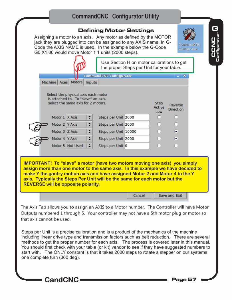
The Axis Tab allows you to assign an AXIS to a Motor number. The Controller will have Motor
Outputs numbered 1 through 5. Your controller may not have a 5th motor plug or motor so
that axis cannot be used.
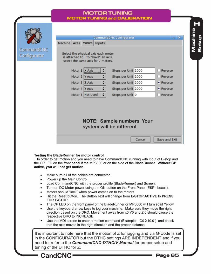
IMPORTANT! To “slave” a motor (have two motors moving one axis) you simply assign more than one motor to the same axis. In this example we have decided to make Y the gantry motion axis and have assigned Motor 2 and Motor 4 to the Y axis. Typically the Steps Per Unit will be the same for each motor but the REVERSE will be opposite polarity.
Steps per Unit is a precise calibration and is a product of the mechanics of the machine including linear drive type and transmission factors such as belt reduction. There are several methods to get the proper number for each axis. The process is covered later in this manual. You should first check with your table (or kit) vendor to see if they have suggested numbers to start with. The ONLY constant is that it takes 2000 steps to rotate a stepper on our systems one complete turn (360 deg).
Defining Motor SettingsAssigning a motor to an axis. Any motor as defined by the MOTOR jack they are plugged into can be assigned to any AXIS name. In G-Code the AXIS NAME is used. In the example below the G-Code G0 X1.00 would move Motor 1 1 units (2000 steps).
Use Section H on motor calibrations to get the proper Steps per Unit for your table.
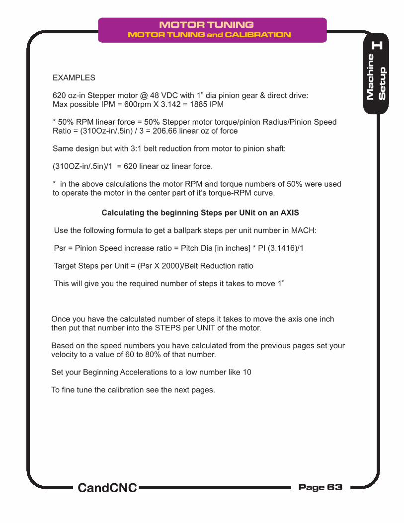
TYPICAL SPUR (PINION ) gears Psr = Pinion Speed increase ratio = Pitch Dia [in inches] * PI (3.1416)/1 = Pitch Dia [in mm] * PI (3.1416)/25.4
Example: 1” Pitch Dia pinion will have a step up ratio speed increase of 3.14 (approx 3)
Belt reduction decreases speed by Raw Speed/Belt Reduction Ratio.Belt reduction increases linear force by normal force X Belt Reduction Ratio.
R
FIXED
R1
R2 R3
Linear Force
Belt Reduction Ratio = R2/R1
Raw Motor Resolution = 1/200 = .005” linear [.127mm] Final linear resolution = .005/Belt Reduction Ratio
P1
P2
P3
Forces: T1= Rated motor holding torque (Oz-in) / R1T2 = Shaft holding torque of P2 = motor holding torque * Belt Reduction RatioT3 = Torque (oz-in at pinion (teeth) = T2 * R3
Note: Motor torque decreases with Motor RPM so a number of about 50% of the holding torque should be used for most calculations.
RACK
Numbers for direct pinion drive are :simply Psr * Motor RPM = IPM (speed) Torque(oz) = T1/ R3
LINEAR MOTION WITH RACK & PINION
Motor constants: (based on stepper motors provided by CandCNC)Typical RPM of hybrid steppers (moderate load) with different DC power 24 VDC = 300 RPM 48 VDC = 600 RPM 65 VDC = 800 RPMNumber of steps for 1 motor REV = 2000 (this a fixed number based on Microstepping X10)
Setting the initial Steps per Unit in CONFIGURATOR motor tuning.Every table will have different Steps Per Unit, Velocity (max speed) and Acceleration settings. To do testing on the table you must determine the correct settings for your table. Use the following method:For Steppers:
1. Determine the number of steps your motors need to make one full revolution (Normally 200 for most steppers)
2. Multiply by the Motor Driver microstepping rate (10 for BladeRunner/Gecko drivers) = 2000 steps for one motor revolution.
3. Determine the drive ratio of your mechanical drive (how far does the leadscrew or pinion move the load with one revolution of the motor).
4. Convert everything to your Units (inches/millimeters) and same time measurements (seconds or minutes).
Using 1 and 2 above we know we have to send 2000 pulses (step pulses) from MACH to rotate the motor one complete revolution (360 Degs).
The rest of the math is based on the transmission ratio(s) between the motor and the final drive element. If it's Rack & Pinion you need to know the DP (diametric pitch) or the tooth count of the pinion gear and the TPU of the Rack (Teeth per unit).If it's a direct drive leadscrew you need to know the treads per unit (TPI for inch units).
We have to determine how far the load moves (in units) for each REV of the motor.
Lets do a direct drive leadscrew of 5 TPI:
It takes 5 turns to move the load one inch of linear movement so the steps per inch (unit) of the axis is simple: 2000 [number of steps for one rev] X 5 [number of Rev to move one inch] = 10.000 steps per
thinch. (.0001”) resolution. About 6 to 7 times the torque. 1/5 the motor Speed.
Now let's do a R & P direct drive and an R & P with a belt reduction transmission:
For a R & P the distance traveled per rev of the pinion is given by the DP of the pinion X PI [3.1416]. If we use a 1” DP pinion the distance traveled is 3.1416” per rev of the pinion So a direct coupled motor gives us over 3” of travel per rev. To get it back to a Unit (1“) it would be the number of steps (2000 from above) / 3.1416 or 636.6183….as you can see, the resolution at .00157 per step is MUCH courser than the 5 TPI leadscrew. The max velocity (speed would be over 8 times the leadscrew but with 1/3 the torque of the motor specs) is over 2000 IPM.
To gain back the lost resolution and torque you should belt reduce between the motor and pinion. With a 5:1 ratio you would see the numbers change to:
2000 /3.14165 X 5 or 3183.1 steps per inch (.000314 inch). Torque would be 1.66 times greater than motor rated torque.
NOTE: DO NOT use the microstepping in a “true” resolution calculation for accuracy. Microstepping is for motion smoothness and cannot be counted on to actually position the motor shaft at a fraction of a motor pole (between poles). It can be off and the faster the motor spins the less effect microstepping has. The only true resolution will be the 2000 steps per rev of the motor. In practice it will be somewhat better especially at slower RPM but it varies.
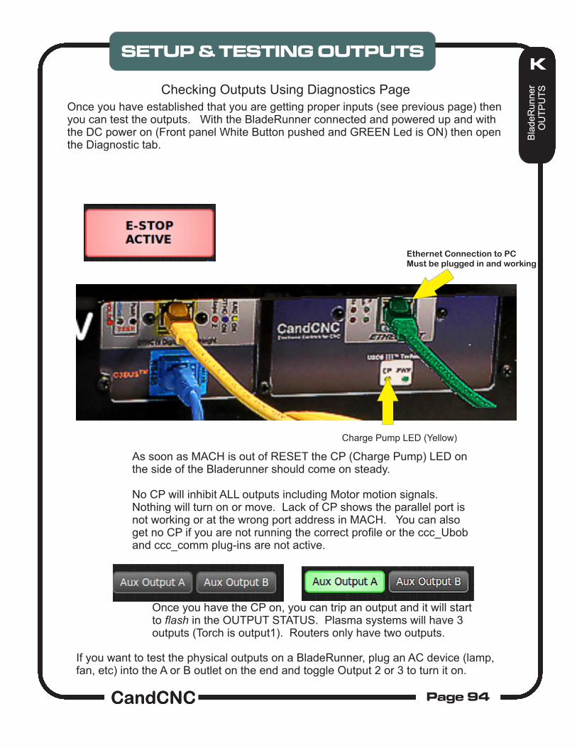
Testing the BladeRunner for motor control. In order to get motion and you need to have CommandCNC running with it out of E-stop and the CP LED on the front panel if the MP3600 or on the side of the BladeRunner. Without CP active, you will not get motion.
Make sure all of the cables are connected. Power up the Main Control. Load CommandCNC with the proper profile (BladeRunner) and Screen. Turn on DC Motor power using the ON button on the Front Panel (ESPII boxes). Motors should “lock” when power comes on to the motors. Hit the Reset button. The Button Text will change from E-STOP ACTIVE to PRESS
FOR E-STOP. The CP LED on the front panel of the BladeRunner or MP3600 will turn solid Yellow Use the keyboard arrow keys to jog your machine. Make sure they move the right
direction based on the DRO. Movement away from x0 Y0 and Z 0 should cause the respective DRO to INCREASE.
Use the MDI screen to enter a motion command (Example: G0 X10.0 ) and check that the axis moves in the right direction and the proper distance.
NOTE: Sample numbers Yoursystem will be different
It is important to note here that the motion of Z for jogging and via G-Code is set in the CONFIGURATOR but the DTHC settings ARE INDEPENDENT and if you need to, refer to the CommandCNC-DTHCIV Manual for proper setup and tuning of the DTHC for Z.
At this point you should have motion on all axis using the keyboard keys to scroll with. In this section we will set the direction of motion for each axis and match the keyboard keys to that motion.
IF YOU HAVE THE MOTORS ON THE BENCH AND LABELED YOU WILL NEED TO ORIENT THEM LIKE THEY WILL BE MOUNTED ON THE TABLE AND WATCH THE DIRECTION OF TURN OF THE SHAFTS. IF YOU DECIDE TO MOUNT THE MOTORS ON THE TABLE, YOU SHOULD DISENGAGE THEM FROM THE TRAVEL MECHANISM UNTIL YOU GET ROTATION DIRECTION RESOLVED. THIS IS ESPECIALLY TRUE FOR THE SLAVED MOTOR ON THE GANTRY AXIS.
1. Load CommandCNC and the Plasma or Router Profile.2. Power up the BladeRunner AIO and the DC to the motors.4. Move Each axis several inches away from the Table 0 (home switch) positions 5. Zero each DRO with Zero Button next to each axis. 5. Jog the Z first. Note the Z DRO as it moves UP. a. If the numbers are INCREASING in value then the direction is correct. b. If the numbers are DECREASING then the direction is wrong. See the image from the CONFIGURATOR / MOTORS screen to reverse the direction of a motor rotation.
7. JOG the non-slaved axis next and do the same DRO check and change if it is scrolling the wrong direction.8. The Slaved Axis is a little different. You must FIRST setup the slaving by assigning two motors to the same axis name 9. If in the setup you need to change the Master Axis DIR to make it move correctly, you will also need to change the Slave Axis on a 4 axis (Software Slave) setup.
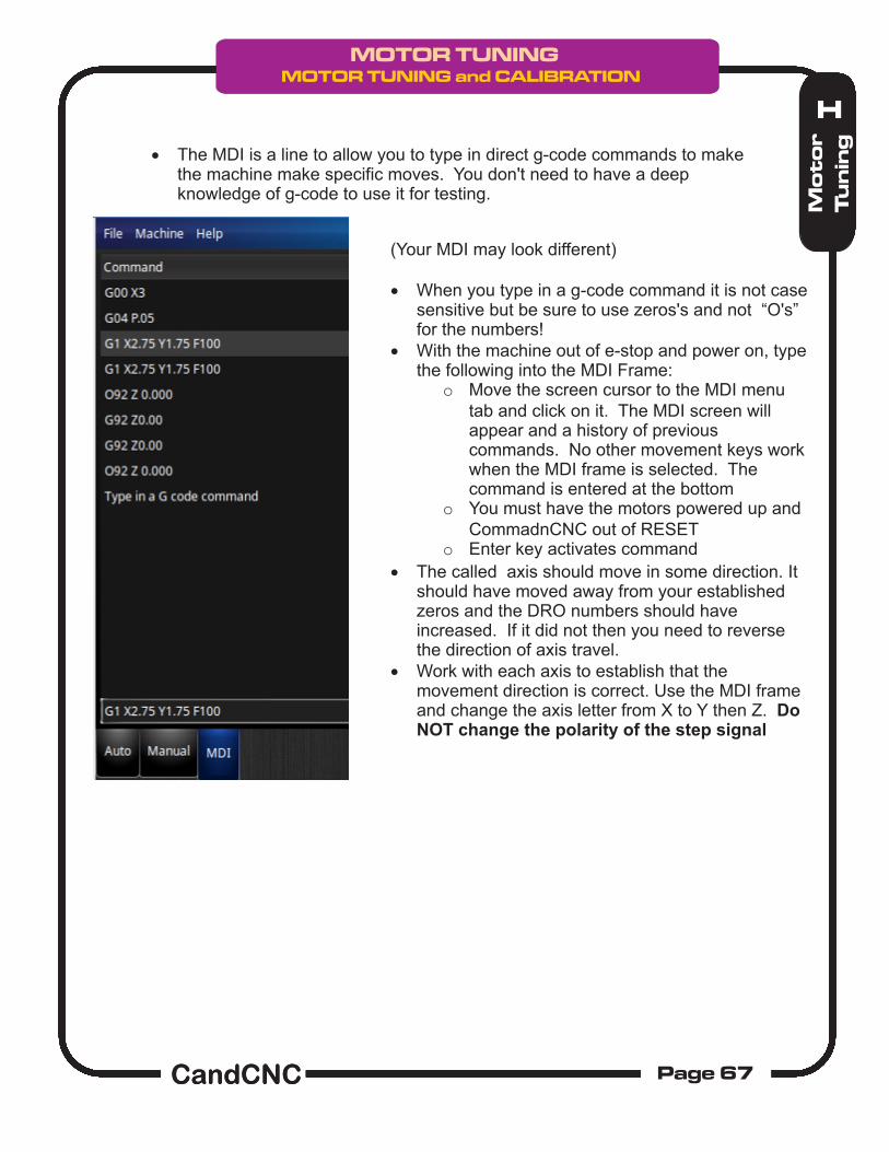
The MDI is a line to allow you to type in direct g-code commands to make the machine make specific moves. You don't need to have a deep knowledge of g-code to use it for testing.
(Your MDI may look different)
When you type in a g-code command it is not case sensitive but be sure to use zeros's and not “O's” for the numbers!
With the machine out of e-stop and power on, type the following into the MDI Frame:
o Move the screen cursor to the MDI menu tab and click on it. The MDI screen will appear and a history of previous commands. No other movement keys work when the MDI frame is selected. The command is entered at the bottom
o You must have the motors powered up and CommadnCNC out of RESET
o Enter key activates command
The called axis should move in some direction. It should have moved away from your established zeros and the DRO numbers should have increased. If it did not then you need to reverse the direction of axis travel.
Work with each axis to establish that the movement direction is correct. Use the MDI frame and change the axis letter from X to Y then Z. Do NOT change the polarity of the step signal
FINE TUNING the calibration using the “tape measure” method
Once you have a ballpark of the number of steps it takes to move your machine 1 inch, then you can fine tune that using a simple tape measure and a calculator.
1. Establish a zero spot you can precisely mark on your table. On a plasma table you need to remove the torch and either mount a laser pointer at tool center or use a sharp pointed tool in a holder. You can also tape a small drill bit or pointer to the torch nozzle if your mount has enough room. You want something small enough you can see errors of .032 on the marks of the tape.
2. Setup up the axis you want to calibrate with the pointer sitting at the zero point and zero that axis DRO.
3. Write down the Steps per Unit value you have for that axis.
4. Open MACH to the Diagnostics Page and find the MDI window.
5. Type in a distance to send that axis out using the following G-Code (example is for moving X out 30 inches). HIT THE ENTER Key to execute the line.
6. Measure the ACTUAL distance you went with your tape measure from zero to where it stopped and write down the distance to as close a decimal value as you can (estimate the distance if it’s less than a 1/16 (.063).7. BEFORE YOU make ANY changes move the axis back to the start point by using the MDI and typing G00 X0.000 (for the example above).8. Use the formula on the next page and calculate the new Steps per UNIT. Then open the motor tuning in MACH and make the change. Run the same test again (you should be MUCH closer. Once you are as close as you can see by eye at 30 inches do one final test at the longest point on that axis. Typically if you are within .032 at the end of the move, you will be within 4 decimal points at 1 inch.
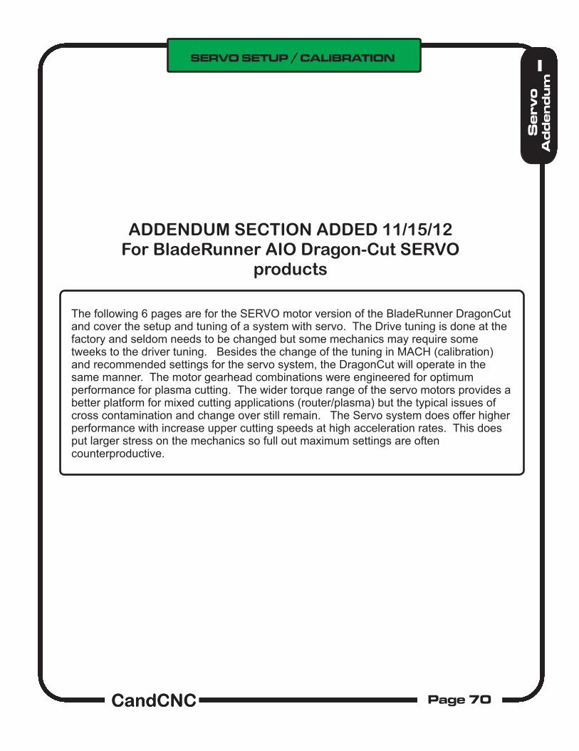
The following 6 pages are for the SERVO motor version of the BladeRunner DragonCut and cover the setup and tuning of a system with servo. The Drive tuning is done at the factory and seldom needs to be changed but some mechanics may require some tweeks to the driver tuning. Besides the change of the tuning in MACH (calibration) and recommended settings for the servo system, the DragonCut will operate in the same manner. The motor gearhead combinations were engineered for optimum performance for plasma cutting. The wider torque range of the servo motors provides a better platform for mixed cutting applications (router/plasma) but the typical issues of cross contamination and change over still remain. The Servo system does offer higher performance with increase upper cutting speeds at high acceleration rates. This does put larger stress on the mechanics so full out maximum settings are often counterproductive.
NOTE: Servo Motors use the same 4 wide motor plug as the BladeRunner Stepper systems but the pinout is different. Do NOT plug a stepper into a servo unit or vice versa!
SERVO systems use a rotary encoder mounted on the motor. Each encoder is supplied with a differential driver (”pigtail”) that allows a standard CAT 5 cable to be plugged in and transmit the encoder information back to the servo interface sub-assembly. You MUST HAVE THE ENCODER CABLES CONNECTED when a motor is powered up! With no feedback to the electronics of where the motor is, it will “Run Away”. We have color coded the label and the cables to make it easier to identify each motor/encoder pair. Do not get the pairs mismatched. The Inputs from the PC parallel and serial port are connected the same way as the stepper version as is the DTHCII connections (see DTHCII User Manual).
The BladeRunner Servo systems ship with 4 (or 5) servo motors and on the XY motors (3) there are 10:1 gearheads. The following pages should be used to do the calculations for the calibration and to determine the best velocity and acceleration. In addition to the normal motor tuning in MACH, the Gecko G320X drives have a PID set of pots that can be used to do added response tuning of each motor. The PID settings are done during final testing prior to shipping and seldom need to be adjusted. We have included excerpts of the tuning process from Gecko but unless you are experiencing motion induced fault issues, than doing adjustments just to see what it does will not “fix” anything. While different loads can alter the response of the servo it will not effect the accuracy. The servos are never at rest if they are powered up. As a result they WILL make noise. If you attempt to tune them for no noise or minimum noise you will have a “sloppy” system. Even a poorly tuned system will not allow a lot of error in position to occur before it faults.
SERVO TUNING 101...Tuning by earIf you don’t have a dual channel oscilloscope and the experience to use it, the easiest way to tune a Gecko drive is by sound. The following covers that method and will yield good results.DO THIS ONLY IF YOU ARE CONFIDENT THAT THE MOTORS ARE EXHIBITING SYMPTOMS OF IMPROPER TUNING! Most problems are mechanical (backlash, loose gears/pulleys or settings in MACH) and cannot be helped with driver tuning.
This should be done ONLY if you experience any of the following:1. Any motor that pulses slowly or is completely quiet when powered and not moving. 2. An axis that faults often when you are accelerating the motion.NOTE: It is normal for a servo to fault and the ESPII to throw a fault when you do an emergency STOP in MACH. The motor cannot stop instantly without causing a fault.Faults from other issues like overloads and noise cannot be fixed with motor tuning!The motors need to be mounted and under load to do tuning by ear.1. Power up the motors. It may be easier to disconnect all but one motor and encoder pair at a time so you can hear just that motor. If you accidently try to jog a motor that is not connected the Gecko drive WILL fault.2. Make sure the motor under test “locks”. If it starts to move than make sure the encoder is plugged in for that motor. If the motor losses encoder pulses (either channel) it will start to run away (spin at full speed hunting for a line on the encoder).3. The motor should “hum”. The frequency is typically below 220 hz (octive 3 A on the music scale). The important thing is that the motor does not sit and pulse indicating it is way over dampened. The higher the frequency of the “hum” the tighter the tuning. There are two main controls: The P and the D pots. The P is the gain and as you increase it the hum frequency will go up.
4. Start with the D pot turned all of the way counterclockwise (minimum) and slowly advance the P pot until you either hit a point it gets unstable and the motor starts to twitch (oscillate) or you have it turned all of the way up. Make a note of the pot position and back it off until the oscillation stops and then advance it to a position below that point. Now increase the D (dampening) and listen to the frequency. It will drop. Stop the D at about 1/4 turn and then advance the P past where it became unstable before. If it starts to become unstable note the position and back it back down then advance the D some. 5. Start with the D and I pot turned all of the way counterclockwise (minimum) and slowly advance the P pot until you either hit a point it gets unstable and the motor starts to twitch (oscillate ) or you have it turned all of the way up. Make a note of the pot position and back it off until the oscillation stops and then advance it to a position below that point. Now increase the D (dampening) and listen to the frequency. It will drop. Stop the D at about 1/4 turn and then advance the P past where it became unstable before. If it starts to become unstable note the position and back it back down then advance the D some more and turn the P back up. The objective is to have high gain but with enough dampening to keep the loop stable under all conditions. Once you have established the highest gain (P) that you can support at a given D then back it off a little and leave the D where it is. Do not set the motor so that it is silent or pulses. After you have the P and D set raise the I and that increases the dampening curve.Once you have the motor tuned in a static (non-moving setup) connect to load, than set the tuning in MACH up to a high number (75 to 100) for acceleration and jog the motors at full speed and change direction several times. If the motor driver faults than lower the P slightly, raise the dampening slightly by increasing the I setting. Once you have one motor tuned correctly listen to the frequency of the sound. Use that as a guide to tune the rest of the motors.
6. Setting the Torque Limit Trimpot. For 23 sized servo motors used on the BladeRunner Servo system, set the Torque Limit Trimpot to ½ range (centered between full CW and CCW rotation. This limits current to 10A max. Leave Dip Switch 10 set to OFF to prevent a 20A 1 sec peak cycle.
SW1 Not used SW2 Current or voltage mode select ON – Current mode (default) OFF – Voltage mode SW3, SW4, SW5 Current mode servo gain SW3 “ON”, SW4 “ON”, SW5 “ON” = Low gain (default) SW3 “ON”, SW4 “OFF”, SW5 “ON” = Medium-low gain SW3 “ON”, SW4 “ON”, SW5 “OFF” = Medium-high gain SW3 “OFF”, SW4 “ON”, SW5 “ON” = High gain SW6, SW7 Sets the G320X pulse multiplier SW6 “ON” and SW7 “ON” = Step pulse times 1 (default) SW6 “ON” and SW7 “OFF” = Step pulse times 2 SW6 “OFF” and SW7 “ON” = Step pulse times 5 SW6 “OFF” and SW7 “OFF” = Step pulse times 10 SW8, SW9 Sets the G320X following error limit SW8 “ON” and SW9 “ON” = +/- 256 count following error limit (default) SW8 “OFF” and SW9 “ON” = +/- 512 count following error limit SW8 “ON” and SW9 “OFF” = +/- 1024 count following error limit SW8 “OFF” and SW9 “OFF” = +/- 2048 count following error limit SW10 Sets the G320X current limit trimpot behavior
EXAMPLES50 oz-in Servo motor @ 60 VDC with 10:1 gearhead and 1” dia pinion gear & direct drive:
Max possible IPM = 4700rpm/10 X 3.142 = 1476 IPM.
* linear force = 100% servo motor continious torque X gear reduction / pinion Radius = (50 Oz-in X 10) / .5 = 1000 linear oz of force
Same design but with 3:1 belt reduction from motor to pinion shaft:
* In the above calculations the motor RPM and torque numbers of 100% were used since servo motor torque does not drop off with RPM. These are maximum numbers and NOT recommended for normal cutting and rapids. High values of velocity and acceleration put maximum stress on components for little benefit.
Calculating the beginning Steps per Unit on an SERVO AXIS
Use the following formula to get a ballpark steps per unit number in MACH
Psr = Pinion Speed increase ratio = Pitch Dia [in inches] X PI [3.1416]
Steps Per Rotation (SPR) of motor = encoder line count X 4; [250 line count = 1000]
Target Steps per Unit = (SPR X gearhead Reduction ratio/PSR)1000 X 10 / 3.1416 = 3183.091 steps per inch
Once you have the calculated the number of steps it takes to move the axis one inch then put that number into the STEPS per UNIT of the motor.
NOTE: IF you have the Step Multiplier on the Gecko set to 2X than you must divide the Steps per Unit by 2
Based on the speed numbers you have calculated from the previous pages, set your velocity to a value of 50 to 80% of that number.
NOTE: MACH can only send the number of pulses per second as set in the Kernel Speed in Ports&Pins. The number of pulses per second you need is the target RPM (max) X the SPR/60. For a target RPM of 4000 and 250 line encoder you need 40000000/60 = 66,666.0 steps per second (66 thousand) if your Kernel speed is set to 45,000 (default) than you cannot achieve 4000 RPM. The step multiplier in the G320X multiples the steps from the PC so a 2X setting makes the steps per second required from the PC to be 33,333. The trade off is that it drops the resolution by ½ as well.
Set your Beginning Acceleration to a low number like 10.
Calculating the max IPM you can travel (limited by max motor RPM )4500 RPM = 75 RPSKernel Speed / SPR = RPS45000/1000 = 45 RPSFinal Speed is limited by the smaller of the above two numbers Pinion RPM = (RPS/ gearratio) X 60IPM = Pinion RPM X Psr
For 45,000 and 250 line encoder:(45000/1000) = 45 RPSPinion RPM = (RPS/10) X 60 = 4.5 X 60 = 270 RPMIPM = 270 X 3.1416 = 848,23
Recommened pinion DIAMETER : 1” (25mm)Recommended belt reduction to pinion : NONEMaximum belt reduction to pinion 2:1Velocity XY and slave : 500 IPM (12700 mm/min)Acceleration XY and Slave 35 to 50 IPS/sec **Steps per unit XYA 3183.091 (1” pinion)Velocity Z (5 turn Leadscrew) 300 IPM (7620 mm/min)Acceleration Z : 20 IPS/SecSteps per unit Z = 1000 X leadscrew TPITHC Rate (Mach setting) 20 **Recommended Span Voltage (Cut Proffile) 4 to 8 **Recommended plunge rate (SheetCAM) 50 - 100 IPMRecommend DTHC Delay (SheetCAM or Cut Profile) 1.5 to 3 sec
** These settings may need to be adjusted depending on your mechanics to get smooth cuts. Always adjust one parameter at a time.
RECOMMENDED SETTINGS FOR BladeRunner Dragon Cutwith 23 Frame servo motors and 10:1 Gearhead reductions
BladeRunner EtherCut Systems are not shipped with the older REV9 and TABLE/IOcards or with the REV 14 or sooner UBOBIII cards. If you find any reference in this manual with regards to those earlier devices, disregard those references.
Setting up HOMES.Homes are used for establishing a known POSITION most often to define the TABLE ZERO locations and be able to return to the same fixed spot. Much like the address on your house versus the location of you RV at any given time. If you establish a TABLE 0 and do all of your cutting in reference to the TABLE ZERO than you can always re-establish your cut at anytime even after a power failure and E-STOP event that can cause the loss of position.
TESTING HOMES at the TABLE I/O.
If you have not yet mounted or wired your HOME switches yet, it is easy to test to make sure of their operation:
1. UNPLUG THE AUXILIARY AC CORD THAT PROVIDES POWER FOR THE AC SOCKETS BEFORE YOU RUN ANY TESTS! You will need to power up the BladeRunner and the DC supply to run the INPUT tests but there is no AC high voltage in the top of the unit UNLESS YOU HAVE THE AUX AC CORD PLUGGED IN.
2. Open the BladeRunner up (remove the cover and place it gently off to one side leaving the cables to the Front Panel plugged in. Expose the TABLE I/O in the top of the case as shown in the illustration on page 73. Note the input terminal pairs are side by side in two rows.
3. Power up the BladeRunner AIO and turn on the DC (Front Panel). You do not need the motors plugged in, but if they are, it is okay. MACH will not come out of RESET if the DC power is off. Inputs do not work right if MACH is in RESET
4. Make sure MACH3 is loaded and the BladeRunner Profile is selected. Open the DIAGNOSTICS PAGE for the test.
5. To test the inputs, use a small screwdriver or metal object to short across a pair of inputs. Start with X Home and go down through A home.
6. Note on the TABLE I/O Card there are small LED’s next to each pair. When you short across a pair you should see the associated LED turn on. That indicates the circuit is complete between the Input on the Table I/O and the UBOBIII. It also confirms the 25 pin cable is working.
Example of testing X HOME input and indications on the DIAGNOSTICS SCREEN. Test each input at a time and match up the INPUT STATUS. The RAW PORT BITS shows the signal AT THE PORT 1 input on the PC as MACH sees it. NOTE: You cannot test the LIMIT input. The AUX 0 is NOT an input for the BladeRunner.
MAKE SURE THE AUX AC INPUT CORD IS DISCONNECTED FROM THE WALL SOCKET BEFORE YOU RUN ANY TESTS
Home Switch Connections: At least one Home (Z) is required if you are using the BladeRunner Dragon-Cut for plasma tables. It is recommended you mount and connect up HOMES for the X & Y but it is not required.
MicroSwitch Type switch with roller lever actuator. Switch has .250 quik connects and a NO and NC set of contacts. Mounting in this case is drilled and tapped AL block with High Strength 3M double-sided tape holding it to the table frame. Switch trips on bottom of gantry frame but allows it to roll past if needed.
Mount your HOME Switches so they define the X and Y zeros on your table. Mount some clips or brackets (stops) on the cutting surface or edges to let you index a sheet of material in relation to the table zero. Even if the STOPS are not exactly at table zero you can deal with the offsets in the CAM layout. Having alignment stops on your table let you accurately remove then re-load a piece of material. Having a defined table 0, 0 that can be referenced to makes the recovery of a loss of absolute position easy to recover from. We have provided enough inputs to allow for up to 4 Homes.
The Z home setup is covered on the next page and depends on the type Floating Torch Holder you are using.
The BladeRunner AIO enclosure is furnished with 2 access holes for routing switch wires into the box for connection to the tabs on the TABLE I/O card. The holes are filled with two rubber knock-out plugs that are easily removed. HOME switch wires carry very small amounts of current (< 15ma) and low voltage (3 -5 volts DC) so the wire size is not critical. It is recommended it be stranded for flexibility on any moving part of the table and for longer runs twisted pair(s) are recommended. Wire from 24Ga to 18Ga works best. The smaller the conductor the more wire pairs will fit through the access holes. Use the correct sized Crimp-On connector for the size wire you use.
Z AXIS FLOATING HEADSWITCH. Close up of switch connections. Use Normally Open Pair.
(Precision Plasma HD Gantry and Z) CONNECTED TO Z HOME in BLADERUNNER on the TABLE I/O
WHAT IS A FLOATING TORCH HOLDER and WHY DO I NEED ONE?
The Floating Torch holder is a torch holder mounted on a separate slide from the Z axis and allows the torch to move UP and DOWN independent of the Z motion. In operation it uses the end of the torch (torch tip) as a “Probe” to find the Top-of-Material. Because metal tends to warp and the slats may not be perfectly level, the Z zero changes (top of the material) as you move around the table surface. The DTHCII will track the rise and fall of the material as it cuts to hold a constant arc gap, BUT the absolute value of Z as displayed by the Z DRO is based on the LAST REFERENCE DONE. (Where it started) Each pierce needs to be done at exactly the right height above the material so a method if Initial Height Sensing (IHS) is needed. The Floating Torch holder lets the Torch be the sensing probe for the IHS. It is a mechanical way to do the probe and is more reliable than ohmic or capacitive sensing. Using a Z homing sequence generated by the G-Code (from SheetCAM) the Z is lowered until the tip of the torch touches the metal and the floating mount allows the torch to be pushed UP and that trips the switch.
Example of a Z with the Floating Torch Holder fordoing the IHS for Plasma cutting.
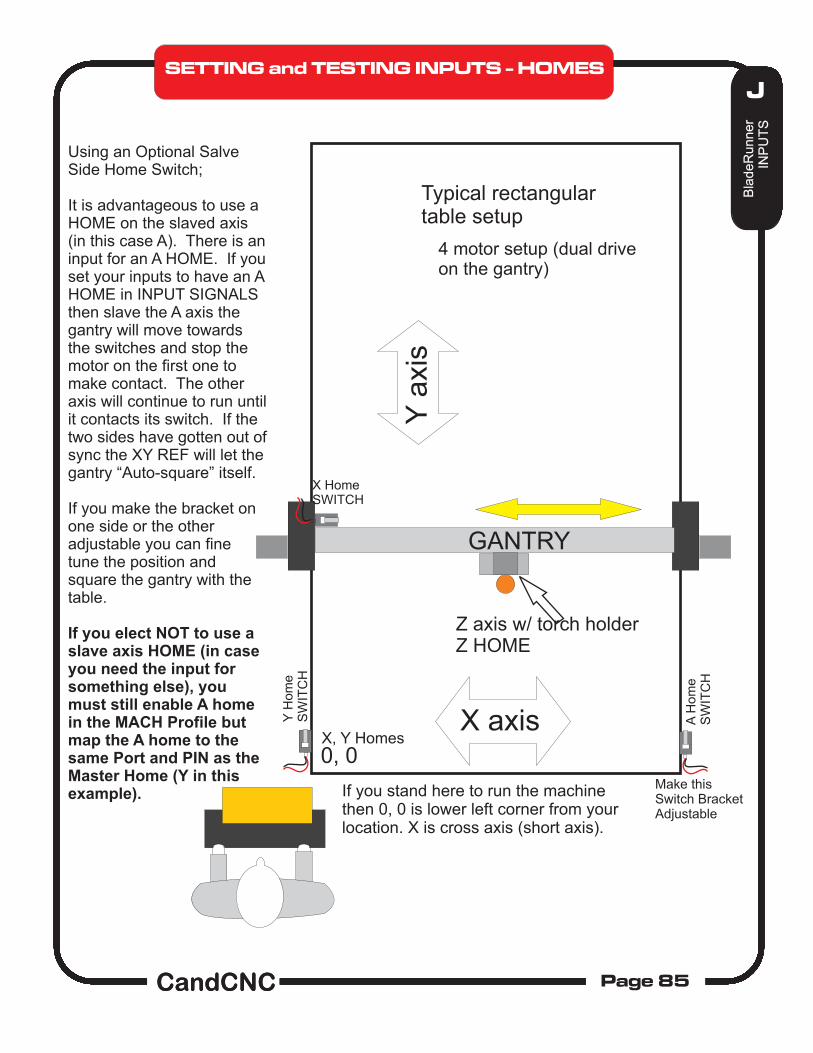
If you stand here to run the machinethen 0, 0 is lower left corner from yourlocation. X is cross axis (short axis).
X axis
Y a
xis
Typical rectangulartable setup
Z axis w/ torch holderZ HOME
4 motor setup (dual driveon the gantry)
GANTRY
X, Y Homes
Y H
om
eS
WIT
CH
X HomeSWITCH
A H
om
eS
WIT
CH
Make thisSwitch BracketAdjustable
Using an Optional Salve Side Home Switch;
It is advantageous to use a HOME on the slaved axis (in this case A). There is an input for an A HOME. If you set your inputs to have an A HOME in INPUT SIGNALS then slave the A axis the gantry will move towards the switches and stop the motor on the first one to make contact. The other axis will continue to run until it contacts its switch. If the two sides have gotten out of sync the XY REF will let the gantry “Auto-square” itself.
If you make the bracket on one side or the other adjustable you can fine tune the position and square the gantry with the table.
If you elect NOT to use a slave axis HOME (in case you need the input for something else), you must still enable A home in the MACH Profile but map the A home to the same Port and PIN as the Master Home (Y in this example).
Normally closed contactsFor far limits. Wired in series
All of the inputs are opto isolated and map to a specific pin on the parallel port(s). In reality you can use any input for any signal. Inputs are not fast enough for Encoder feedback faster than a few pulses per second. The inputs use a “floating” ground (+12 return). If you need more inputs than the 8 (9 with EPO) then a PORT 2 card can be hooked to the UBOB and the added Aux and BHome inputs will work with a second parallel port.
The X Home should light up when you manually activate X Home switch. It should be off when the switch is not active. If it is reversed (i.e. goes OFF when you activate the switch but stays on otherwise) you will need to reverse the polarity of the switch in Ports & Pins/ Input Signals. We recommend using normally open (NO) contacts on Homes and Normally Closed (NC) contacts on the far limits (if used).The far limits are wired in series external to the Table I/O card and it is setup so breaking the string at any point activates a hard limit. The hard limits are safety switches located at points on the table to prevent the machine from going past the table travel limits. You can have far limits (opposite the 0,0 location of the table) AND near limits (at points where the machine would crash on the other side of the Home switches. Limits are optional and on stepper based systems you could elect to have just hard stops since the motors can be stalled without damage.
A NOTE ABOUT LIMITS on the BladeRunner:A stepper motor/driver is a “torque limited system” meaning that the drives limit the amount of torque a stepper motor can apply to a load. It does that by limiting the current on each pulse. While most AC and DC motors will quickly exceed their ratings if presented with a large overload, the stepper just stalls (starts slipping) and “loses steps”. Because of this they are safe from overload and will simply stop turning. Simple mechanical stops on an axis will keep motors from running too far and no damage to motor or drive is inflicted. It sounds bad because the motor vibrates as it attempts to turn but no harm is done. The motor will not overheat and the electronics will not see it as an overload unless all 4 motors are stalled at the same time. LIMITS are more for decoration than function on a stepper system. Some users like to have them. If that describes you then by all means install and set them up...you will feel much better!
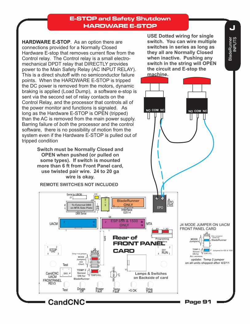
In CommandCNC there is a mandatory input for E-STOP. It is implemented as a normally closed input (must be held low to come out of RESET). That input is assigned in the BladeRunner AIO to EPO. With nothing attached to that pin it is pulled high interface card. IF CommandCNC is in RESET, all outputs are disabled and no inputs are acted on (ignored).
There is a general misunderstanding about software E-stop and if it is safe if the motors are still under power. The answer lays in the fact that a stepper based system like the BladeRunner HAS TO HAVE PRECISE TIMED SIGNALS to special drivers to initiate motion. It cannot simply “run away”. It is virtually impossible to make a stepper motor turn without the operating software (LinuxCNC) and the electronics providing a valid pulse stream. In any failure scenario of the hardware (drive malfunction, shorted/open signals, disconnected wires, loss of power, etc) motor rotation is not possible. Since the software MUST be in control to issue pulses and the Charge Pump will turn off if the software is frozen, in a loop, or malfunctioning, putting the software into RESET for any reason will stop motion. It is actually harder to get motion when you SHOULD have it than to have a stopped system. One of the added benefits to a stepper based control is IF IT DOES NOT HAVE VALID STEP COMMANDS IT LOCKS THE MOTORS if power is still on the drives. Any consequence of applying DC or a short to any motor winding will cease rotation and typically lock the motor. The only argument is that the input device for E-STOP might fail, but that is no more likely than a failure of a HARDWARE based e-stop. So a failed drive will not cause a stepper motor to Run Away. A failed computer or communications interface will not result in random or uncontrolled motion. Coupled with the Charge Pump (see section on the Charge Pump function) the probability of any motion more than .050 inches is about the same as a computer attached to a printer and no keyboard activity (no user) firing up and printing a perfect copy of the Magna Carta from random noise.
Since it REQUIRES concise control from the software to create motion the software can effectively control it going into RESET and E-STOP
The user can willfully disable Software E-STOP by setting the E-STOP input to read the wrong polarity and render the E-STOP disabled but a hardware E-stop can be disabled as well.
Implementing a SOFTWARE (ONLY) E-STOP. The BladeRunner AIO when properly setup will be put into RESET if the E-STOP (EPO) string is broken.
J6ESPIISupplyBypass
ESPII Control relayNC when ON
EPO CONTACTSON TABLE I/O CARD
Wired Jumper
+ +IsolatedPowerSupply
Visible LED
System is ACTIVE ON. All connections, voltages and components MUST be intact and working OR the system will Software E-STOP. Anytime power is off MACH cannot come out of reset. Jumper at EPO can be a string of “N...” switches (NC in series) that can be wired at any point on the equipment. any switch or connection in the string that open will trigger an E-stop. Once closed condition is restored, the operator must initiate a RESET to bring the system back out of Software E-Stop.
E-STOP and Safety Shutdown
DANGER ZONEWHEN AUX AC CORD IS PLUGGED IN
CONNECTED TO TABLE I/O HEADER ON UBOB III CARD
EPO MUST BE JUMPERED (Closed). Jumper can be replaced by one or more Normally Closed Switches (in series) for Software E-STOP
Switch must be Normally Closed and OPEN when pushed (or pulled on some types). If switch is mounted
more than 6 ft from Front Panel card, use twisted pair wire. 24 to 20 ga
wire is okay.
USE Dotted wiring for single switch. You can wire multiple switches in series as long as they all are Normally Closed when inactive. Pushing any switch in the string will OPEN the circuit and E-stop the machine.
REMOTE SWITCHES NOT INCLUDED
MODEJumpers
TEMP 2SensorON for
ALL versions
TEMP2 KILL
J1
MODE
7 8
J4
2
4
1
3
5 6
50/60 HZ50hz =Jumpered
BladeRunner
Jumpered for 650 & 1500
J4 MODE JUMPER ON UACMFRONT PANEL CARD
Grey = no jumper
update: Temp 2 jumperon all units shipped after 4/2/11
E-STOP and Safety Shutdown
HARDWARE E-STOP
HARDWARE E-STOP. As an option there are connections provided for a Normally Closed Hardware E-stop that removes current flow from the Control relay. The Control relay is a small electro-mechanical DPDT relay that DIRECTLY provides power to the Main Safety Relay (AC INPUT RELAY). This is a direct shutoff with no semiconductor failure points. When the HARDWARE E-STOP is tripped the DC power is removed from the motors, dynamic braking is applied (Load Dump), a software e-stop is sent via the second set of relay contacts on the Control Relay, and the processor that controls all of the power monitor and functions is signaled. As long as the Hardware E-STOP is OPEN (tripped) than the AC is removed from the main power supply. Barring failure of both the processor and the control software, there is no possibility of motion from the system even if the Hardware E-STOP is pulled out of tripped condition
OUTPUT Status (Cont). There are two AUXILLARY OUTPUT Relays on a BladeRunner EtherCut Plasma AIO unit. They are designed as Output 2 and Output 3 on the Buttons and they toggle ON/OFF the AC Outlets A and B on the end of the BladeRunner Box. These AC outlets are wired to the AUX AC line cord on the BladeRunner. That cord must be plugged in before the outlets can be used. CAUTION! There is high voltage (120VAC ) at the Relays and the Outlets. DO NOT OPERATE THE BLADERUNNER WITH THE AUX AC CORD PLUGGED IN AND THE TOP COVER REMOVED.
On a BladeRunner Plasma Profile (with DTHC) OUTPUT 1 is used for turn on the TORCH Relay located out on the THC SENSOR PWM. Operation is covered in depth in the DTHCII User Manual but it is easy to simply plug in the THC SENSOR PWM module to the DTHCII module using the 25ft UTP Cable and test the TORCH ON by toggleing the TORCH button on the Diagnostics Screen and watching the TORCH LED on the front of the THC SENSOR PWM module. You can test the other two AUX outputs by plugging in the AUX AC cable and plugging in an AC load (table lamp, 120VAC FAN . etc) and toggling the individual outputs on and off.
The AUX outlets can also be turned ON and OFF from G-code using an “M” command. The M command that is used to turn on/off an OUTPUT, is a setting in MACH and comes defaulted so a M03 or M04 turns on OUTPUT1 (Torch on the Plasma Profile, Spindle on the Router Profile. M05 turns OFF either.
Once you have established that you are getting proper inputs (see previous page) then you can test the outputs. With the BladeRunner connected and powered up and with the DC power on (Front panel White Button pushed and GREEN Led is ON) then open the Diagnostic tab.
Charge Pump LED (Yellow)
As soon as MACH is out of RESET the CP (Charge Pump) LED on the side of the Bladerunner should come on steady.
No CP will inhibit ALL outputs including Motor motion signals. Nothing will turn on or move. Lack of CP shows the parallel port is not working or at the wrong port address in MACH. You can also get no CP if you are not running the correct profile or the ccc_Ubob and ccc_comm plug-ins are not active.
Once you have the CP on, you can trip an output and it will start to flash in the OUTPUT STATUS. Plasma systems will have 3 outputs (Torch is output1). Routers only have two outputs.
If you want to test the physical outputs on a BladeRunner, plug an AC device (lamp, fan, etc) into the A or B outlet on the end and toggle Output 2 or 3 to turn it on.
SETUP & TESTING OUTPUTS
Ethernet Connection to PCMust be plugged in and working
In the Plasma setup for CommandCNC Output 1 is the primary (TORCH) output. It should be left that way of the POST for SheetCAM will turn on the wrong output (or not fire the Torch. The following M codes are used in LINUXCNC to activate the three defined outputs:
Primary (Torch) ON = M3 Primary OFF = M5 AUX A ON = M7 AUX A OFF = M9 AUX B ON = M8 AUX B OFF = M9
Turning on/off other outputs
The G-Codes to directly control other outputs are constructed as follows.
Once you have setup and tested your BladeRunner EtherCut system, you are ready to proceed with setting up and tuning the DTHC IV Digital Torch Height Control if you have the Plasma version of the BladeRunner. Use the DTHC IV Setup and Config Manual provided to add this feature.