I. Overview Blanchard grinding is the term often used to describe surface grinding using a vertical spindle, rotary table machine. The most common of such machines were made by Blanchard, though very similar machines are also available from other manufacturers. These versatile surface grinders come in a variety sizes and capable of achieving very accurate flatness and fine finishes. Through various fixturing techniques, they are capable of grinding a wide range of shapes, sizes and materials. This booklet is meant to provide some basic operating guidelines and tips in abrasive selection and job set-up. II. General Considerations A. Load Areas and Configurations Table loads of 35% to 50% have been found to be most practical for solid parts. Load areas greater than that amount tend to make the wheel cut ‘hard’ or sluggish, while smaller loads tend to make the wheel cut ‘soft’. The parts are best aligned on the table in a circular band or in concentric squares or polygons near the outer 6” to 9” of the table equal in width to 1/5 th the table diameter. The parts should be aligned on the table so that they pass through the center of the grinding wheel. The following table illustrates the optimal table load for various sized machines: Table Size Total Table Area Optimal Load Area Grinding Band Width 30 in. 706 sq. in. 236-353 sq. in. 6 in. 36 in. 1018 sq. in. 339-509 sq. in. 7.25 in. 42 in. 1386 sq. in 462-693 sq. in. 8.5 in. 48 in. 1809 sq. in. 603-905 sq. in. 9.5 in. 60 in. 2827 sq. in. 942-1414 sq. in. 12 in. 80 in. 5027 sq. in. 1676-2513 sq. in. 16 in. 100 in. 7854 sq. in. 2618-3927 sq. in. 20 in. 120 in. 11309 sq. in. 3765-5658 sq. in. 24 in.
Transcript
I. Overview
Blanchard grinding is the term often used todescribe surface grinding using a verticalspindle, rotary table machine. The mostcommon of such machines were made byBlanchard, though very similar machines arealso available from other manufacturers.
These versatile surface grinders come in avariety sizes and capable of achieving veryaccurate flatness and fine finishes. Throughvarious fixturing techniques, they arecapable of grinding a wide range of shapes, sizes and materials.
This booklet is meant to provide some basic operating guidelines and tips in abrasiveselection and job set-up.
II. General Considerations
A. Load Areas and Configurations
Table loads of 35% to 50% have been found to be most practical for solid parts. Loadareas greater than that amount tend to make the wheel cut ‘hard’ or sluggish, whilesmaller loads tend to make the wheel cut ‘soft’.
The parts are best aligned on the table in a circular band or in concentric squares orpolygons near the outer 6” to 9” of the table equal in width to 1/5th the table diameter.The parts should be aligned on the table so that they pass through the center of thegrinding wheel.
The following table illustrates the optimal table load for various sized machines:
Table Size Total Table Area Optimal Load Area Grinding Band Width30 in. 706 sq. in. 236-353 sq. in. 6 in.36 in. 1018 sq. in. 339-509 sq. in. 7.25 in.42 in. 1386 sq. in 462-693 sq. in. 8.5 in.48 in. 1809 sq. in. 603-905 sq. in. 9.5 in.60 in. 2827 sq. in. 942-1414 sq. in. 12 in.80 in. 5027 sq. in. 1676-2513 sq. in. 16 in.
100 in. 7854 sq. in. 2618-3927 sq. in. 20 in.120 in. 11309 sq. in. 3765-5658 sq. in. 24 in.
B. Feeds & Speeds
The correct balance between table speed and downfeed rate is most important. A fewgeneral rules relative to this are:
o The fastest downfeed rate and table speed which give optimum ratios or rates ofremoval should be used.
o As areas become broader than 50% of the table area, feed rates generallydecrease.
o As heat or burn becomes a factor, table speeds are changed.o As areas become more ‘broken’ and less than 35% of the table area, feed rates
should drop accordingly.
Area and configuration have a large bearing on the efficiency of a wheel and this, in turn,affects the feeds and speeds.
C. Motor Loads
These machines are normally equipped with ammeters that measure the motor load on thegrinder. This measurement is a good means to monitor the work being done by thegrinder. The meters normally indicate either the percentage of load or some measure theactual amperage on the motor. The meters that read the percentage of load are morecommon and have scales that are color coded and have a maximum reading of 150%.
Percent motor loads on Blanchard grinders can be run at 120% to 135% motor loadswhile Mattison grinders can be operated at 85% to 105% motor load.
The nature of the part, contact area, feeds and speeds all have a bearing on the motorload. Under normal circumstances, attempts should be made to run the grinder at thehighest practical motor load.
D. Performance Ratios
The following are definitions of commonly used performance measurements:
1. Linear Ratio – This is the ratio of the linear abrasive wear to the linear stockremoval. It is commonly used as a guide for the operator to set the amount oftotal downfeed required to remove a stated amount of stock. This ratio givesinformation that is applicable only to very similar jobs, as it does not take intoconsideration the total care of the parts being ground.
2. ‘G’ Ratio – This is a comparison of the total volume of stock removed to the totalvolume of abrasive used. The higher the ‘G’ ratio, the more efficient theoperation. However, the ‘G’ ratio is not the ultimate measurement of grindingefficiency as very high ratios can be obtained through the use of overly hardabrasive grades with low downfeed rates and increased grinding time.
3. Rate of Removal – This is a measure of the grinding time versus the volume ofmaterial ground.
Thus, ‘G’ Ratio can be used to measure amount of abrasive used, and the Rate ofRemoval can be used to measure the machine time required. Both have real costsassociated with them and neither alone represents the cost of the operation. However,when combined, they give an excellent means to monitor the total cost of the grindingoperation.
III. Abrasive Selection
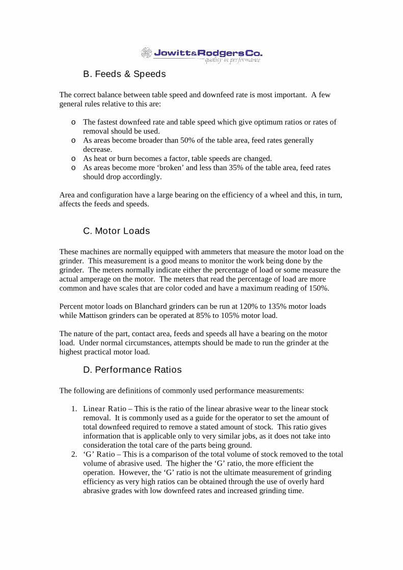
Efficient grinding requires that theproper abrasive is used that bestmatches the job. Abrasive wheelsfor these types of grinders can eitherbe solid wheels or segmentedwheels.
Abrasives are made of abrasive grain, which are the materials that do the actual cutting,and bonding materials that hold the wheel together. The abrasive materials are usuallyforms of either Aluminum Oxide or Silicon Carbide and the bonding materials areusually either vitrified or resin.
The choice abrasive grain is normally determined by the material being ground. Thegrains, through their chemistry, have varying properties of hardness, friability andsharpness. These are matched to the physical properties of the material being ground togive the most appropriate cutting action. The grain is also available in a wide range ofparticle sizes, referred to as grit size. This is matched as well to both the part materialand tolerance of the operation to provide the optimum results, where coarser grits areused for soft materials and high stock removal.
The bond is the glue that holds the abrasive grain in the wheel. ‘Harder’ grades hold thegrain more firmly than ‘softer’ grades. Vitrifed bonds are glass like bonds fired at veryhigh temperatures. Resin bonds are usually phenol/formaldehyde resins that are baked atrelatively low temperatures. At Jowitt & Rodgers Co. we make only resin bondedproducts.
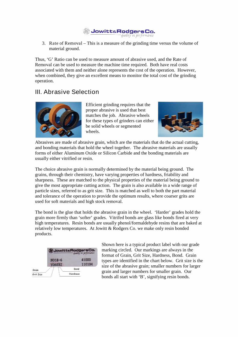
Shown here is a typical product label with our grademarking circled. Our markings are always in theformat of Grain, Grit Size, Hardness, Bond. Graintypes are identified in the chart below. Grit size is thesize of the abrasive grain; smaller numbers for largergrain and larger numbers for smaller grain. Ourbonds all start with ‘B’, signifying resin bonds.
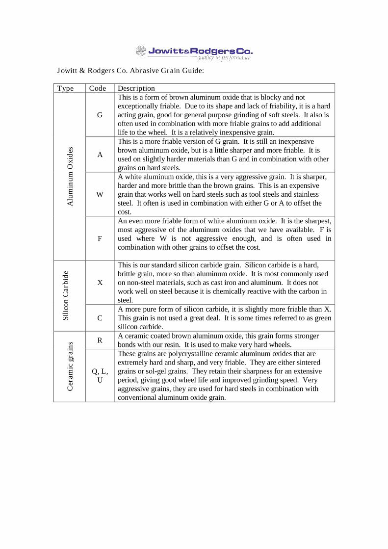
Jowitt & Rodgers Co. Abrasive Grain Guide:
Type Code Description
G
This is a form of brown aluminum oxide that is blocky and notexceptionally friable. Due to its shape and lack of friability, it is a hardacting grain, good for general purpose grinding of soft steels. It also isoften used in combination with more friable grains to add additionallife to the wheel. It is a relatively inexpensive grain.
A
This is a more friable version of G grain. It is still an inexpensivebrown aluminum oxide, but is a little sharper and more friable. It isused on slightly harder materials than G and in combination with othergrains on hard steels.
W
A white aluminum oxide, this is a very aggressive grain. It is sharper,harder and more brittle than the brown grains. This is an expensivegrain that works well on hard steels such as tool steels and stainlesssteel. It often is used in combination with either G or A to offset thecost.
Alu
min
umO
xide
s
F
An even more friable form of white aluminum oxide. It is the sharpest,most aggressive of the aluminum oxides that we have available. F isused where W is not aggressive enough, and is often used incombination with other grains to offset the cost.
X
This is our standard silicon carbide grain. Silicon carbide is a hard,brittle grain, more so than aluminum oxide. It is most commonly usedon non-steel materials, such as cast iron and aluminum. It does notwork well on steel because it is chemically reactive with the carbon insteel.
Silic
onC
arbi
de
CA more pure form of silicon carbide, it is slightly more friable than X.This grain is not used a great deal. It is some times referred to as greensilicon carbide.
R A ceramic coated brown aluminum oxide, this grain forms strongerbonds with our resin. It is used to make very hard wheels.
Cer
amic
grai
ns
Q, L,U
These grains are polycrystalline ceramic aluminum oxides that areextremely hard and sharp, and very friable. They are either sinteredgrains or sol-gel grains. They retain their sharpness for an extensiveperiod, giving good wheel life and improved grinding speed. Veryaggressive grains, they are used for hard steels in combination withconventional aluminum oxide grain.
This chart gives some guidelines for whichtype of grain to use for various materials.These are general suggestions only. Ceramicgrains may also be used as well for most ofthese materials, depending upon the actualrequirements of the job.
IV. Abrasive MountingInstructions
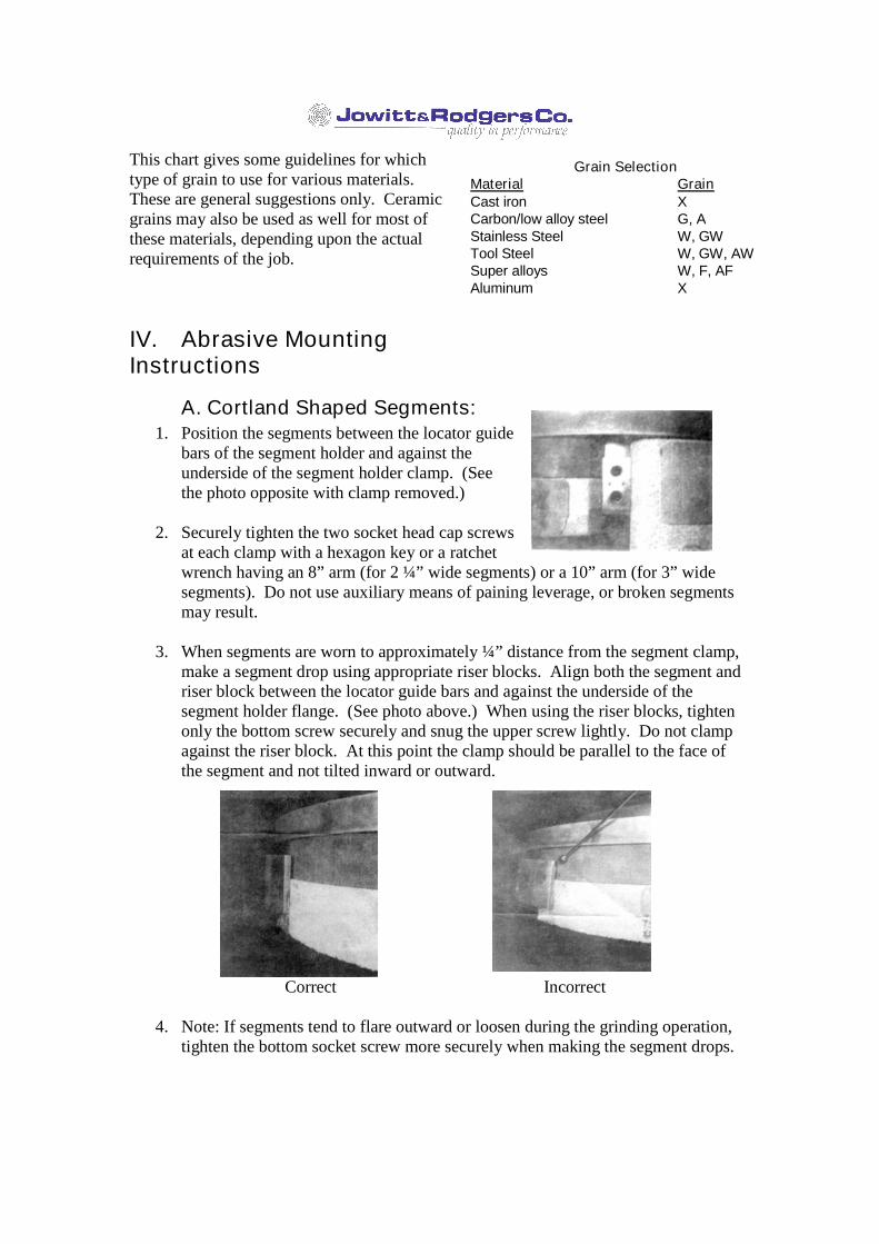
A. Cortland Shaped Segments:1. Position the segments between the locator guide
bars of the segment holder and against theunderside of the segment holder clamp. (Seethe photo opposite with clamp removed.)
2. Securely tighten the two socket head cap screwsat each clamp with a hexagon key or a ratchetwrench having an 8” arm (for 2 ¼” wide segments) or a 10” arm (for 3” widesegments). Do not use auxiliary means of paining leverage, or broken segmentsmay result.
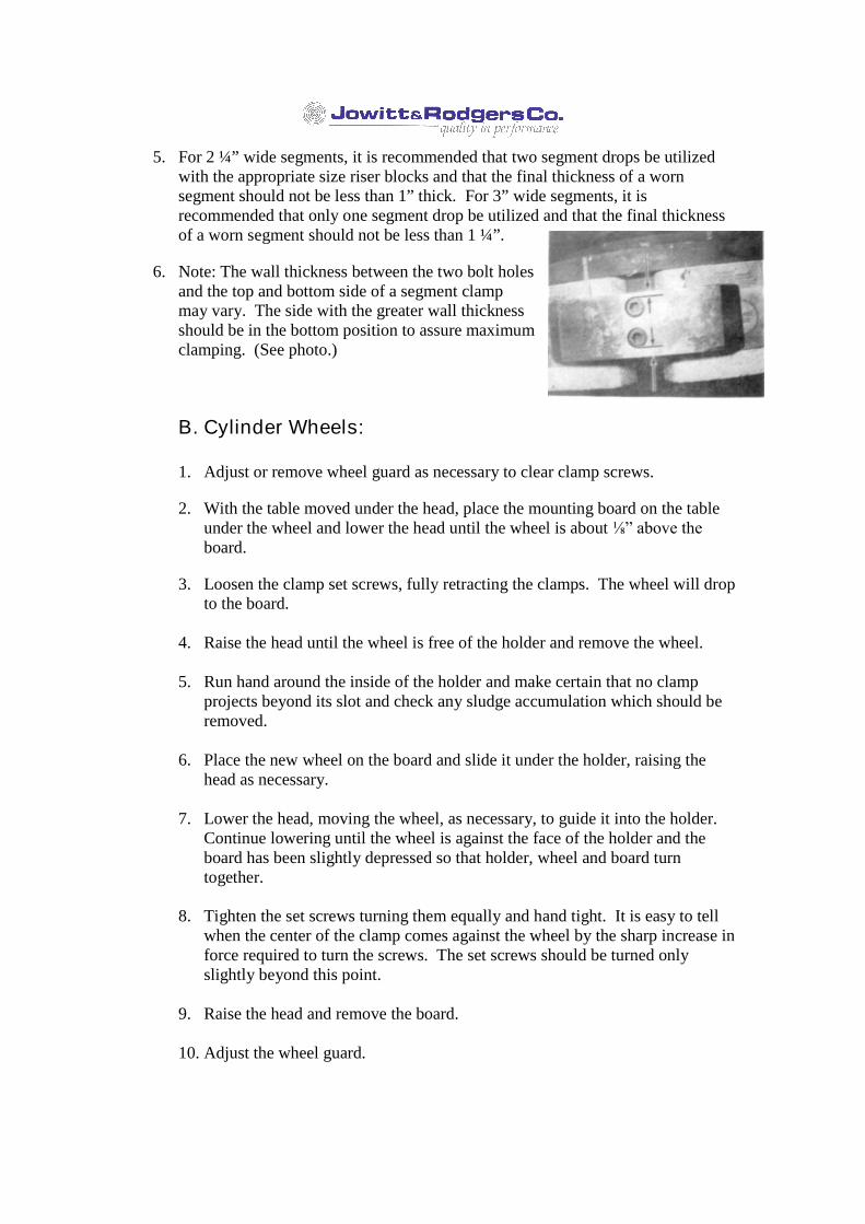
3. When segments are worn to approximately ¼” distance from the segment clamp,make a segment drop using appropriate riser blocks. Align both the segment andriser block between the locator guide bars and against the underside of thesegment holder flange. (See photo above.) When using the riser blocks, tightenonly the bottom screw securely and snug the upper screw lightly. Do not clampagainst the riser block. At this point the clamp should be parallel to the face ofthe segment and not tilted inward or outward.
Correct Incorrect
4. Note: If segments tend to flare outward or loosen during the grinding operation,tighten the bottom socket screw more securely when making the segment drops.
5. For 2 ¼” wide segments, it is recommended that two segment drops be utilizedwith the appropriate size riser blocks and that the final thickness of a wornsegment should not be less than 1” thick. For 3” wide segments, it isrecommended that only one segment drop be utilized and that the final thicknessof a worn segment should not be less than 1 ¼”.
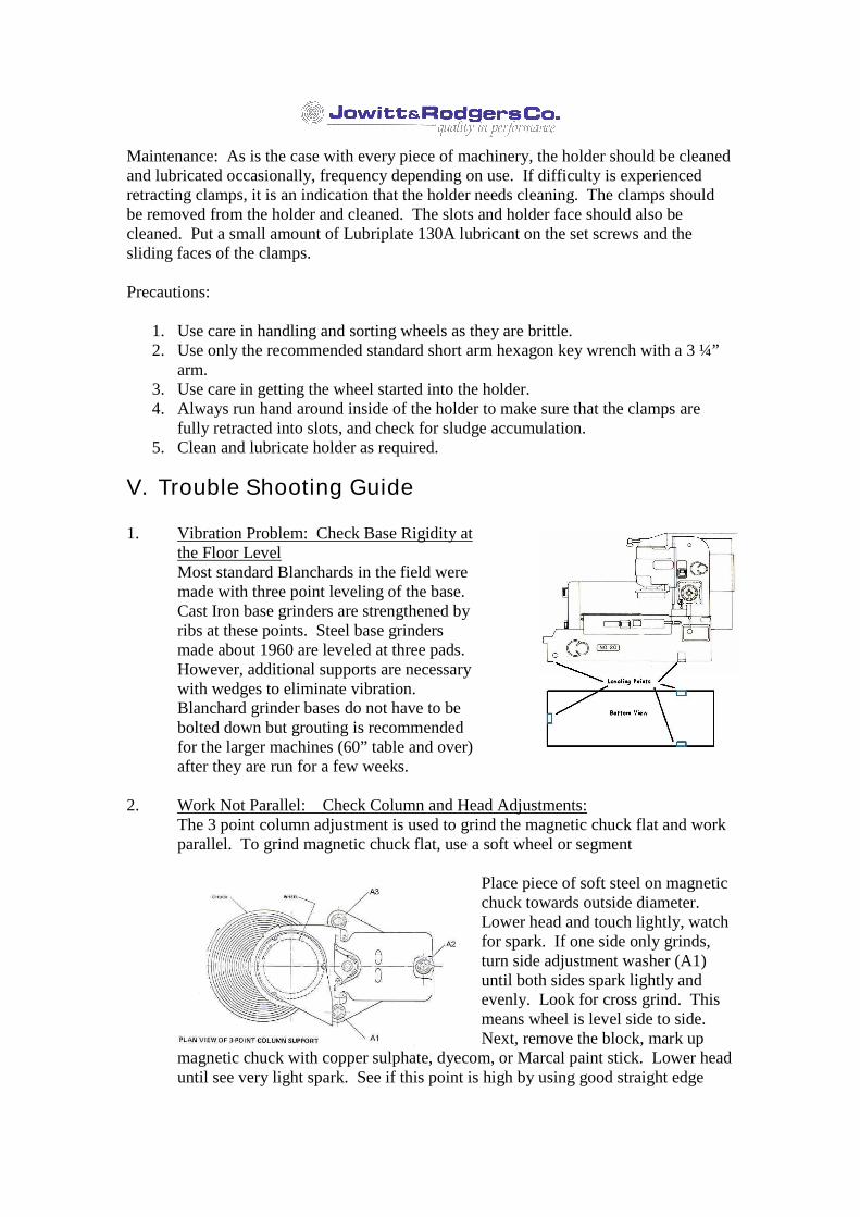
6. Note: The wall thickness between the two bolt holesand the top and bottom side of a segment clampmay vary. The side with the greater wall thicknessshould be in the bottom position to assure maximumclamping. (See photo.)
B. Cylinder Wheels:
1. Adjust or remove wheel guard as necessary to clear clamp screws.
2. With the table moved under the head, place the mounting board on the tableunder the wheel and lower the head until the wheel is about ⅛” above the board.
3. Loosen the clamp set screws, fully retracting the clamps. The wheel will dropto the board.
4. Raise the head until the wheel is free of the holder and remove the wheel.
5. Run hand around the inside of the holder and make certain that no clampprojects beyond its slot and check any sludge accumulation which should beremoved.
6. Place the new wheel on the board and slide it under the holder, raising thehead as necessary.
7. Lower the head, moving the wheel, as necessary, to guide it into the holder.Continue lowering until the wheel is against the face of the holder and theboard has been slightly depressed so that holder, wheel and board turntogether.
8. Tighten the set screws turning them equally and hand tight. It is easy to tellwhen the center of the clamp comes against the wheel by the sharp increase inforce required to turn the screws. The set screws should be turned onlyslightly beyond this point.
9. Raise the head and remove the board.
10. Adjust the wheel guard.
Maintenance: As is the case with every piece of machinery, the holder should be cleanedand lubricated occasionally, frequency depending on use. If difficulty is experiencedretracting clamps, it is an indication that the holder needs cleaning. The clamps shouldbe removed from the holder and cleaned. The slots and holder face should also becleaned. Put a small amount of Lubriplate 130A lubricant on the set screws and thesliding faces of the clamps.
Precautions:
1. Use care in handling and sorting wheels as they are brittle.2. Use only the recommended standard short arm hexagon key wrench with a 3 ¼”
arm.3. Use care in getting the wheel started into the holder.4. Always run hand around inside of the holder to make sure that the clamps are
fully retracted into slots, and check for sludge accumulation.5. Clean and lubricate holder as required.
V. Trouble Shooting Guide
1. Vibration Problem: Check Base Rigidity atthe Floor LevelMost standard Blanchards in the field weremade with three point leveling of the base.Cast Iron base grinders are strengthened byribs at these points. Steel base grindersmade about 1960 are leveled at three pads.However, additional supports are necessarywith wedges to eliminate vibration.Blanchard grinder bases do not have to bebolted down but grouting is recommendedfor the larger machines (60” table and over)after they are run for a few weeks.
2. Work Not Parallel: Check Column and Head Adjustments:The 3 point column adjustment is used to grind the magnetic chuck flat and workparallel. To grind magnetic chuck flat, use a soft wheel or segment
Place piece of soft steel on magneticchuck towards outside diameter.Lower head and touch lightly, watchfor spark. If one side only grinds,turn side adjustment washer (A1)until both sides spark lightly andevenly. Look for cross grind. Thismeans wheel is level side to side.Next, remove the block, mark up
magnetic chuck with copper sulphate, dyecom, or Marcal paint stick. Lower headuntil see very light spark. See if this point is high by using good straight edge
across center of magnetic chuck. If it is – continue grinding while dressingfrequently with very little motor load. If magnetic chuck is concave or convex,re-adjust rear adjusting bushing (A2). Move bushing counterclockwise ifmagnetic chuck is concave and clockwise if it is convex.
When the magnetic chucks surface is flat to .001” feeler gage then use 6 to 8 oneinch strips of good magazine paper with hard surface to it. This paper should betorn from one sheet with the grain so edge will feather out.
When these 6 to 8 papers are tight under straight edge (which should be testedwith these strips on good surface plate first), the magnetic chuck will be flat to afew tenths of a thousand of an inch. Do not use indicator to check chuck!! It isimportant to finish the last grind with very little power work from sliding asmagnet only holds work down but does not prevent pieces from sliding except bythe friction between the pieces and magnetic chuck surface. If work is groundand finished this way, very close tolerances can be had.
3. Work Not Parallel: Consider Temperature Change:To grind to light wave bands for flatness in the grinding of optical flats, gageblocks, surface plates and tool makers flats the rear locking bolt (A2) of theadjustment bushing is used by slightly loosening or tightening with a long wrenchthat can be used as a vernier. As temperature of the day increases or temperaturerises from grinding heat, this lock down bolt is tightened a little at a time until atthe end of the day it is up tight. The next morning this excessive pressure isreleased and adjusted to secure the flatness wanted to start the day. Directsunlight on column will cause deflection.
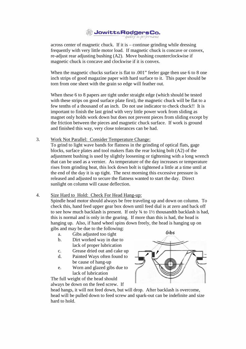
4. Size Hard to Hold: Check For Head Hang-up:Spindle head motor should always be free traveling up and down on column. Tocheck this, hand feed upper gear box down until feed dial is at zero and back offto see how much backlash is present. If only ¾ to 1½ thousandth backlash is had,this is normal and is only in the gearing. If more than this is had, the head ishanging up. Also, if hand wheel spins down freely, the head is hanging up ongibs and may be due to the following:
a. Gibs adjusted too tightb. Dirt worked way in due to
lack of proper lubricationc. Grease dried out and cake upd. Painted Ways often found to
be cause of hang-upe. Worn and glazed gibs due to
lack of lubricationThe full weight of the head shouldalways be down on the feed screw. Ifhead hangs, it will not feed down, but will drop. After backlash is overcome,head will be pulled down to feed screw and spark-out can be indefinite and sizehard to hold.
Corrective action: Remove one gib at a time, clean gib, ways and way coverusing flat rod with swab soaked in a chemical cleaner. Reflake or frost gibs toproduce lubrication pockets. Replace in same position. Check for .002”-.003”clearance using feeler gage between gibs and ways. It is better to have theseslightly loose than a little too tight. On older grinders it may be hard to usefeelers. Recommend that three gibs be tightened down solidly and then back offfive turns of nut on stud that holds these gibs in place. This will give ampleclearance from the tightest spot on worn ways. If excessive backlash is still hadafter doing above, loosen one gib at a time until minimum backlash is secured.Keep well lubricated to keep dirt out of ways and wipe off surplus grease.
5. Bouncing Wheel and Blotchy Finish: Check “Preload” of Spindle:Blanchards up to 1935 had spring pre-loaded at top of spindle. A large nut helddown eight springs. This nut was adjusted by using a spanner wrench. Springswere collapsed solid and then nut backed off one full turn. To check preload,place a bar between face plate and the head. Movement should be had whenprying down and then spindle should snap up solidly.
The next 10,000 standard grinders have fixed spring preloads built into lower endof spindle and are not adjustable. When face plate is uptight, check with barbetween face plate and head. Pull down with bar and when released, spindle willsnap back solid. On these models, twenty springs were used and preload isapproximately 1200 lbs.
The latest standard grinders (about Serial#10,000 and up) have a Timken Bearingat lower end and an adjustable spring preload at top. The ten springs each haveadjustable screws. To set preload, take up on each one until they are all solid.Back off one-half to one turn each and 1200 – 1400 lbs. preload will be had.Make test as above with bar.
6. No Accuracy at Different Head Heights From Table:To check column and head ways, use indicator clamped to segment or wheelchuck. Swing this through center of magnetic chuck and record reading at center,left and right sides of magnetic chuck with head as low as possible. Repeat this atdifferent heights of head. Instead of lowering this indicator use a block left,center and right. Repeat using blocks of different heights. Correct by rescrapingways to remove concave or convex ways.
7. Parts Not Parallel: Check Base and Table Ways:After magnetic chuck is ground flat at full “in” position, put two pieces onmagnetic chuck, one on outside and the other about 6 inches from the center.Clean grind these pieces with table all the way in. Check both pieces for height.They should be the same. Replace in same position as before. Mark up bothpieces and run table all the way in and then back out again about 5 inches. Grindblocks to clean and check for height. If different, the base and table ways areworn concave or convex. To overcome error – rescrape ways. If you do not wantto rescrape ways, then I recommend that only roughing be done with table out –so wheel can be dressed while grinding. Finish grind with table all the way in
since this is position where table was ground. (If larger diameter wheel orsegment chuck can be used, this will overhang magnetic chuck and table will beground flat. Dressing can then be done at all times while grinding and accuracymaintained.)
8. Wheel Too Hard For Large Work Areas:a. Tilt head so wheel will cut on back side away from operator. This reduces
area of wheel in contact and puts double pressure on one side of wheel.b. Step grind large pieces. Bring table in approximately one-third of the way
to grind about 50% of the area. Recommended over tilting head. Our ruleof thumb for best efficiency when grinding: load area should not exceed100 square inch per 10 horsepower of motor. When it does – step grind.
c. Positioning of table affects power even when medium areas are ground.Move table out as far as possible while still covering the work. Amps candrop as much as 10%.
9. Feeds, Speeds and General Information Affecting Wheel Performance:a. Increase downfeed to force wheel to break down.b. Adjust table speed when roughing. Average table speed should be 100
ft./minute. This depends on area and where parts are placed on table.Near the edge of 36” diameter table – run at 9 or 12 rpms. Nearer center,increase table speed.
c. Dress slowly when finishing to “clean” all grains. Dressing quicklyroughs part of wheel face but causes blotchy finish.
d. Mounting Cortland type segments always tighten bottom screw first –especially when using lowering blocks. Recommend loosen all top screwsfirst before lowering. Then loosen bottom screws on 2 clamps and removeand replace one segment at a time, snugging up bottom screw. Avoidcracking segment by strong clamp pressure.
e. Vary magnetic power of table through DC power source. Machines areset for full holding power. Lower holding power is used when grindingbow out of pieces. Use just enough power to keep parts from moving.
f. Problem of squealing wheels – May times squealing is caused byovertightening clamps in wheel holds. Use normal hand pressure withstandard 5 inch Allen wrench. This will generally stop the squeal andimprove performance.