1 | Page Blind User Accessible Insulin Pump Michigan State University Senior Design-ECE 480-Team 4 Fall 2014 Project Sponsors: Resource Center for Persons with Disabilities Asante Solutions Marathon Oil Team Members: August Garrett Michael Greene Jianwen Lu Caitlin Ramsey Faculty Facilitator: Dr. Robert McGough December 3, 2014
Transcript
1 | P a g e
Blind User Accessible Insulin Pump
Michigan State University
Senior Design-ECE 480-Team 4 Fall 2014
Project Sponsors: Resource Center for Persons with Disabilities
Asante Solutions Marathon Oil
Team Members:
August Garrett Michael Greene
Jianwen Lu Caitlin Ramsey
Faculty Facilitator: Dr. Robert McGough
December 3, 2014
2 | P a g e
Executive Summary
The need for an accessible insulin pump is becoming a major problem for a growing population of sight-impaired diabetics. The ECE480 design team is attempting to solve this dilemma by creating an auditory add-on component for insulin pumps that will speak the necessary verbal commands to a blind user. Asante Solutions has been generous enough to provide the team with their Snap Insulin Pump, which was used for reverse engineering and testing the add-on component’s functionality. There are two main areas of focus for integrating this project into the blind patients’ everyday life. The first is creating a link between the insulin pump screen display and a corresponding verbal command. Based on its current LCD screen command, the Snap Pump will send an associated ASCII 8-bit code to a microcontroller within the add-on component. This microcontroller will then output an auditory response, via a digital speech chip, to direct the user towards the screens description and next course of action. The second area of focus is creating a user-friendly method of helping the patient navigate through the pump’s various button roles. Capacitive touch is the chosen method of providing this button feedback response. When any button on the pump is touched, the microcontroller will detect the change in capacitance and instruct the digital speech chip to verbalize an audio response detailing that specific button’s function. This report will give an analysis of the project background and requirements, design strategies, individual design components, milestones schedule, and testing criteria.
3 | P a g e
Acknowledgements
This project could not be completed without the assistance and support of a variety of key individuals. Specifically, Michigan State University faculty members, Dr. Robert McGough and Stephen Blosser were continuously involved in the progression of the design. Dr. Robert McGough is a professor within the Department of Electrical and Computer Engineering and acted as the group’s facilitator. He was willing to take the time every week to meet with the group and discuss current and future design aspects of the model. Through Professor McGough’s guidance, the project was able to progress in a timely and efficient manner. Stephen Blosser is a Technology Specialist at the Resource Center for Persons with Disabilities at Michigan State University and was instrumental in developing the initial idea for this project. Stephen discovered the need for a blind user accessible insulin pump and set up the connection to the sponsor, Asante Solution. He also aided in providing the group with doctors and nurses to interview, as well as blind individuals to provide input and test the design.
Additionally, the group would like to thank Mark Estes and Jin Jang from Asante Solutions for sponsoring this project. Mark Estes is the Vice President of Asante Solutions and the main reason for Asante’s involvement in the venture. Along with Asante’s financial support, Mr. Estes also provided the group with the Snap Insulin Pump, which was used for reverse engineering and testing the add-on component. Jin Jang is a technical expert at Asante Solutions. He provided the group with valuable information and technical documents detailing the Snap Pumps inner workings. Mr. Jang, along with Mr. Estes, also delivered a software program, development board, and cable connections. These were vital for further investigation into the pumps outputs and connecting the pump to the project.
Marathon Oil also offered a generous financial contribution towards the project. For this, the group is extremely grateful.
4 | P a g e
Table of Contents
Chapter 1 – Introduction and Background .................................................................................................. 6
Chapter 2 – Exploring Possible Solutions .................................................................................................... 8
FAST Diagram ............................................................................................................................................ 8
Final Cost ................................................................................................................................................. 32
Projected Mass Production Cost ............................................................................................................. 33
Final Schedule ......................................................................................................................................... 34
August Garrett ........................................................................................................................................ 35
Michael Greene ....................................................................................................................................... 36
Jianwen Lu ............................................................................................................................................... 37
Energia Code ........................................................................................................................................... 40
Final System Connection Schematic ........................................................................................................ 56
According to the Generic Insulin Infusion Pump model (GIIP), seen in Figure 1.1 above, the main functional component in an insulin pump is the pump controller. It manages the pump delivery mechanism to provide the patient with insulin at a prescribed rate and duration. The pump controller is responsible for the user interface, recommending appropriate dosage, alerting the patient, and logging important data. All these features are extremely important to a diabetic patient, but the flexibility of the insulin pump’s user interface remains to be seen. Nurses and doctors agree that current insulin pumps on the market need to better address patients of various age groups and disabilities. In the United States, approximately 40% of diagnosed diabetics have a form of diabetic retinopathy, which leads to decreased vision and blindness. This represents a significant portion of diabetics, whom the insulin pump manufacturing industry is not addressing. Asante Solutions and the Resource Center for Persons with Disabilities are working with our team to create possible solutions to this ongoing problem. Asante Solutions is a company located in Sunnyvale, California that is focusing on bringing a sensible solution to diabetics across the globe. The Resource Center for Persons with Disabilities here at Michigan State University is trying to do the same thing, make those with disabilities’ lives easier, focusing on Michigan State University students.
Currently, nurses are adding magnifying glass to high contrast screens in order to help their patient better see the screen on the insulin pump. Also, doctors are teaching their patients how to use the insulin pump. The main concern with these practices is that patients forget how to use the insulin pump and/or the addition of a magnifying glass only helps patients distinguish large print, but not small print. At the 2010 AAMI/FDA Infusion Device Summit, nurses and doctors voiced their opinions on how infusion pumps could be made easier to use. From these concerns, it’s easy to see that not only blind patients are worried with how they interact with their medical devices. Nurses and doctors alike are troubled with how insulin pumps are made without thought for older and/or handicapped patients:
Offering a magnifying glass that fits over screens, larger print or brighter screens.
Offer pumps screen text in more languages.
Explore the effectiveness of alarm tones on different age groups.
The inclusion of a strong vibrating alarm to help alert sleeping or inattentive patients.
Figure 1.1: Generic Insulin Infusion Pump Model
7 | P a g e
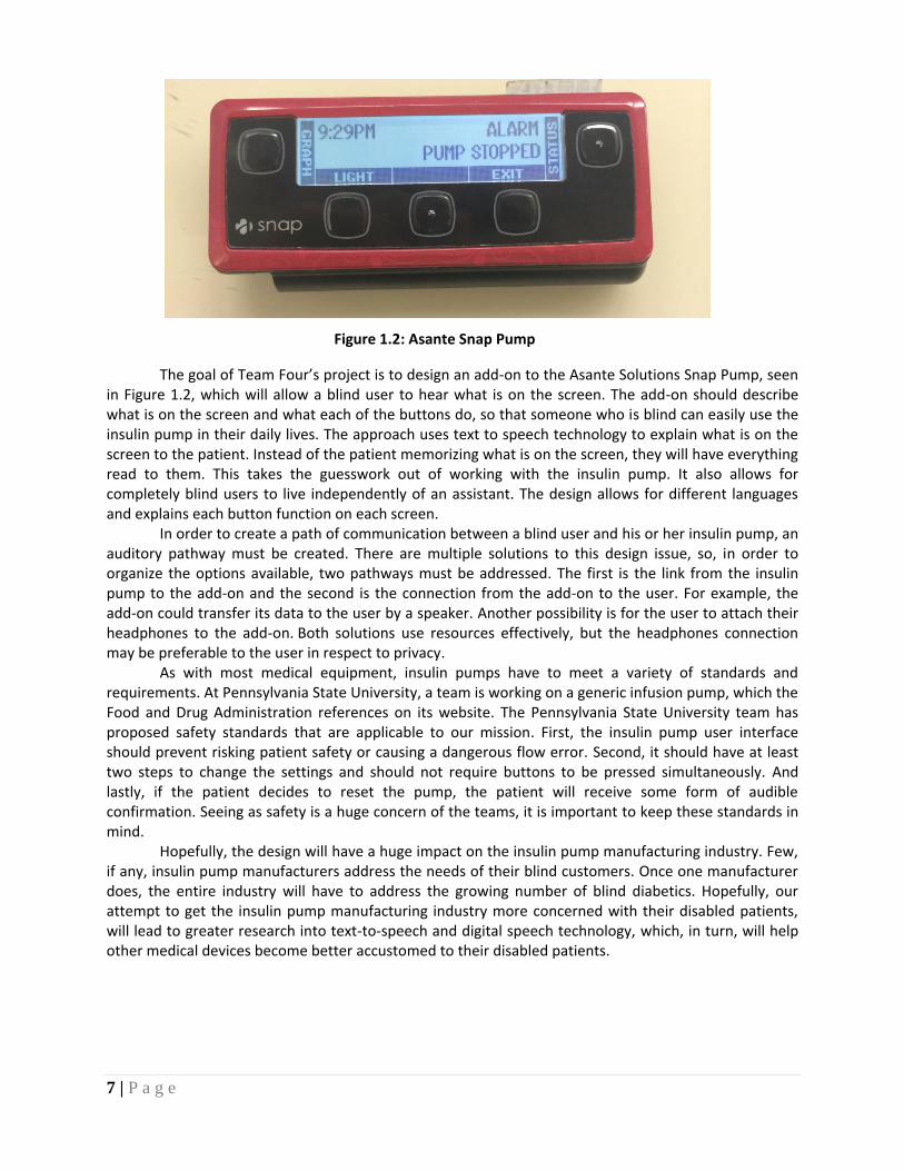
The goal of Team Four’s project is to design an add-on to the Asante Solutions Snap Pump, seen in Figure 1.2, which will allow a blind user to hear what is on the screen. The add-on should describe what is on the screen and what each of the buttons do, so that someone who is blind can easily use the insulin pump in their daily lives. The approach uses text to speech technology to explain what is on the screen to the patient. Instead of the patient memorizing what is on the screen, they will have everything read to them. This takes the guesswork out of working with the insulin pump. It also allows for completely blind users to live independently of an assistant. The design allows for different languages and explains each button function on each screen.
In order to create a path of communication between a blind user and his or her insulin pump, an auditory pathway must be created. There are multiple solutions to this design issue, so, in order to organize the options available, two pathways must be addressed. The first is the link from the insulin pump to the add-on and the second is the connection from the add-on to the user. For example, the add-on could transfer its data to the user by a speaker. Another possibility is for the user to attach their headphones to the add-on. Both solutions use resources effectively, but the headphones connection may be preferable to the user in respect to privacy.
As with most medical equipment, insulin pumps have to meet a variety of standards and requirements. At Pennsylvania State University, a team is working on a generic infusion pump, which the Food and Drug Administration references on its website. The Pennsylvania State University team has proposed safety standards that are applicable to our mission. First, the insulin pump user interface should prevent risking patient safety or causing a dangerous flow error. Second, it should have at least two steps to change the settings and should not require buttons to be pressed simultaneously. And lastly, if the patient decides to reset the pump, the patient will receive some form of audible confirmation. Seeing as safety is a huge concern of the teams, it is important to keep these standards in mind.
Hopefully, the design will have a huge impact on the insulin pump manufacturing industry. Few, if any, insulin pump manufacturers address the needs of their blind customers. Once one manufacturer does, the entire industry will have to address the growing number of blind diabetics. Hopefully, our attempt to get the insulin pump manufacturing industry more concerned with their disabled patients, will lead to greater research into text-to-speech and digital speech technology, which, in turn, will help other medical devices become better accustomed to their disabled patients.
Figure 1.2: Asante Snap Pump
8 | P a g e
Understand LCD Screen
Produce Speech
Collect ASCII Signal
Detect Incoming Signal
Form Connection Between Devices
Build Pathway
Build Fastening
Decode Signal Develop Translation
Algorithm
Convert Signal Develop Conversion
Algorithm
Produce Outgoing Signal
Form Connection Between Devices
Reconstruct Signal
Produce Signal
Perform Transform Operations
Create Audio Signal
Produce Connections
Detect Audio Signal Create Input
Produce Audio Signal
Create Output
Amplify Audio Signal
Perform Amplification
Chapter 2 – Exploring Possible Solutions FAST Diagram
Figure 2.1 shows how the team approached the design of the accessible insulin pump by
breaking it down into a fast diagram. In order to produce a device that can be used by blind patients, the design was broken into two communication pathways, incoming signal and output audio signal. The first pathway, the add-on collecting the ASCII signal from the insulin pump, was broken down into two parts again. In order to detect the incoming signal, convert the signal, and produce a new signal, the team broke down the pathway, again, into its software and hardware components. The hardware components would be creating the serial connection between the insulin pump and add-on. The software component would be the algorithm that would convert the incoming signal into coherent messages.
Producing the audio signal the user would hear was also broken down into software and hardware components. The software components were the same as the ASCII signal pathway. The hardware would have to be able to produce an audio signal perceptible to the user. Essentially, the design was broken down into hardware and software. There were two sets of hardware, the two different pathways: serial connection between insulin pump and add-on and the audio connection between add-on and user. The software would be the bridge that would connect these two different types of hardware together.
Figure 2.1: FAST Diagram
9 | P a g e
Critical Customer Requirements
In order to determine the critical customer requirements for this project, the team developed a House of Quality table. When creating this table, the team developed a list of the most important design constraints as well as which components would help develop the most ideal design for customers. After analyzing the House of Quality, it was concluded that creating a device with the best sound quality and smallest size would best help benefit our customers. Also, the House of Quality calculations helped determine that using a speech chip that was both small in size and did not exceed a voltage rating of 9V would be an important constraint moving forward.
Figure 2.2: House of Quality
10 | P a g e
Feasibility Matrix
While originally planning how to go about creating the add-on unit, heavy effort was spent developing a set of specific design criteria to optimize the products appeal. Of these design criteria, the majority of the emphasis was directed towards four key areas: safety, cost, size, and durability. Initially, there were three methods considered for producing the audio component of the add-on device: text to speech, digital speech, and Bluetooth. The importance of these criteria, as well as each design method’s feasibility, is detailed further in Table 2.3 below.
Design Criteria Importance Possible Solutions
Text-to Speech
Digital Speech Bluetooth
Safety 5 4 3 1
Size 4 2 4 5
Weight 4 3 4 5
Cost 3 5 4 2
Intuitiveness 3 4 4 5
Simplicity 3 3 5 4
Reliability/Durability 5 4 4 3
Programming 4 2 3 1
Power 4 2 3 4
Totals
112 130 113
Table 2.3: Feasibility Matrix
Since this is a medical device dealing directly with a patient’s health, safety was the group’s top concern. Careful steps were taken to avoid making any modifications that could potentially hinder the pumps functionality. Anything from drawing power from the pumps battery to tampering with the pumps microcontroller could have detrimental effect to any user.
Next to safety, cost was second most essential of these design criteria. While gathering all the necessary components, every effort was initially spent to find the cheapest parts possible. However, as the design phase progressed, it quickly was realized that the cheapest parts were unlikely to produce the effects necessary for a functional user-friendly design. Therefore, the group learned that a balance must be established between cost and ideal functionality. If too much focus is spent on the cost, the fact that the product doesn’t work as intended will greatly overshadow the cheapness of it. Essentially, the end goal was modified towards creating the best product possible at the lowest cost.
Another important criterion was durability of involved materials, specifically the casing piece. This unit will be on the patient 24/7, so it must be able to withstand the normal wear and tear of everyday life, while still being lightweight and comfortable. Currently, the case of this prototype created through 3D printed plastic. This is lightweight, but not very durable, so future models should likely be created with a sturdier type of plastic material. Lastly, size is an important aspect of the final creation. As mentioned above, the patient will be wearing this device continually throughout the day. Therefore, the unit must be as small as physically possible as to avoid interfering with the patient’s day-to-day activities. Throughout the fabrication process, every intention was made to meet as much of this design
11 | P a g e
criterion of possible. However, in some situations, the standards had to be adjusted to achieve a desired function. Initial Budget
The proposed budget for our final design included all of the parts needed to construct our add-on. The team aimed to stay within a budget of $500. Keeping the add-on at a low cost was essential to our design because Asante Solutions sells the Snap Insulin Pump at a cheaper price than most of their competitors. Several of the parts that were used including the MSP430G2553 Launchpad, copper conductive tape, and the SPST circuit board switch were provided either through ECE 480 lab or the ECE shop free of charge. The budget shown in Table 2.3 totals the actual cost to the team, as well as the total cost of all of the items if they needed to be purchased. The final cost for all of these items totaled to $232.71, well below our target budget. The most expensive items for this project included the V-Stamp digital speech chip at $82.00 and the V-Pod development board costing $45.00, which was used to program the V-Stamp chip. This budget focuses only on the items used to complete the proposed Digital Speech option and a full budget for every part purchased during the duration of completing this project, as well as a budget detailing the projected cost for producing multiple units can be found in Chapter 5 of this report.
Item Quantity Cost per Unit
Gross Total Total
V-Stamp 1 $82.00 $82.00 $82.00
V-Pod Development Board 1 $45.00 $45.00 $45.00
MSP430g2553 Launchpad 1 $9.99 $9.99 $0.00
Electrical Tape 1 $4.19 $4.19 $4.19
Copper Conductive Tape 1 $2.95 $2.95 $0.00
SPST Switch 1 $5.49 $5.49 $0.00
9 Pin Serial to USB Connector 1 $17.95 $17.95 $17.95
6 Pin Serial to USB Connector 1 $39.99 $39.99 $39.99
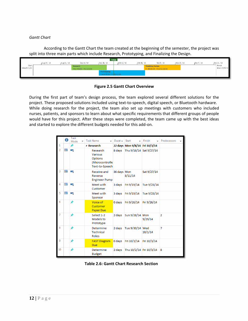
According to the Gantt Chart the team created at the beginning of the semester, the project was split into three main parts which include Research, Prototyping, and Finalizing the Design.
Figure 2.5 Gantt Chart Overview
During the first part of team’s design process, the team explored several different solutions for the project. These proposed solutions included using text-to-speech, digital speech, or Bluetooth hardware. While doing research for the project, the team also set up meetings with customers who included nurses, patients, and sponsors to learn about what specific requirements that different groups of people would have for this project. After these steps were completed, the team came up with the best ideas and started to explore the different budgets needed for this add-on.
Table 2.6: Gantt Chart Research Section
13 | P a g e
For the Prototyping portion, the main factor for the team was to order all of the required parts and build each component for the add-on separately including the capacitive touch, V-stamp circuit, and power supply. Also during this stage the team aimed to solve any design problems immediately as they arose in order to remain on schedule.
Table 2.7: Gantt Chart Prototyping Section
14 | P a g e
For the Finalizing the Design section, the team’s goal was to have all of the components of the project working together and focus on refining the design. After this was completed, the team would aim to contact certain blind individuals to help test the effectiveness of our design. The group also created a durable case to contain the unit during this stage and tested aspects such as the power supply.
Table 2.8: Gantt Chart Finalizing the Design Section
15 | P a g e
Chapter 3 – Technical Description of Work Performed Hardware Implementation Initial Hardware Design Efforts:
SpeakJet: The Sparkfun SpeakJet and Text to Speech IC chips were used in the initial design for text to speech technology, as seen in the schematic in Figure 3.1. The SpeakJet design used an Arduino microcontroller to send ASCII signals to the Text-to-Speech IC. The Text-to-Speech IC converted the ASCII signals into allophones the SpeakJet could read. The SpeakJet had a robotic voice, which made it hard to understand different combination of letters. The design did not allow for different languages or a better voice to be programmed into the SpeakJet. Consequently, the SpeakJet design was deemed inflexible and bulky, so it was not used in the final design.
Selected Design Solution
For the add-on the team primarily searched for components that were both small and light weight. The group also aimed to obtain devices that consumed little power and were able to be powered with anything 9V or less since the battery powering the Snap Pump is 9V. Size and power consumption were important because no large, heat producing items should be included in the final device for this would cause levels of discomfort for insulin pump users. Also, devices that would not in any way interfere with the functionality of the Snap Pump in performing its insulin delivery duties so we avoided any components that used wireless communication as a direct form of communication.
Figure 3.1: SpeakJet and Arduino Circuit Schematic Figure 3.2: SpeakJet and Arduino Circuit
16 | P a g e
MSP430:
In order to solve some of the issues posed by this project, the team chose the MSP430G2553 LaunchPad microcontroller to be the control part of the add-on, which means that all the information coming from the Snap Pump will go through the MSP430 before any orders are sent from it. Also, the team was familiar with using MSP430 because all members of the team used it during the completion of the color-organ lab at the beginning of ECE 480 lab. The MSP430G2553 contains a 16MHz CPU and its relatively inexpensive cost of about $10 made it an attractive choice. The MSP430 also has both receive(RX) and transmit(RX) UART pins that are able to receive ASCII code directly from the Snap Insulin Pump and transmit any information to the V-Stamp digital speech chip. The inclusion of two UART ports was the deciding factor in choosing this microcontroller. The MSP430 proved successful in converting incoming ASCII code into words that the V-Stamp speech chip could understand. The LaunchPad runs off of a 3.3V power supply, which is ideal since the V-Stamp requires the same voltage. The Launchpad’s small size of 2.5inches long and 2inches wide helped with the overall packaging of the final design.
V-Stamp: In completing this project, the team used RC Systems’ V-Stamp, which is based off of RC
Systems’ Double Talk RC8660 as the digital speech chip in our add-on for the Snap insulin pump. The V-Stamp was chosen as opposed to the actual RC8660 speech chip because it contains two 12 pin PC board connectors which were essential in interfacing multiple devices for our add-on. The V-stamp is a feature-rich, self-contained voice and sound synthesizer and also a digital recorder. The V-Stamp is also a relatively small circuit device with a surface area of 1.7in2. For the V-stamp, it possesses several features that are beneficial for this project. It contains a text-to-speech processor, audio recording and playback capabilities, and musical and sinusoidal tone generation. These functions are allowed for great versatility in creating an add-on for the Snap insulin pump. The V-Stamp is able to operate off of either a 3.3V or 5V power supply, which allows for great flexibility since the MSP430, which is also being used, operates off of 3.3V as well. This device satisfies the standards of having low power consumption because it uses only 3.8mA when active and 700µA idle at 3.3V.
Figure 3.3: MSP430G2553 LaunchPad
17 | P a g e
Some of the reasons the V-Stamp was chosen is because it is easily programmable with the RC Studio software and it has both text-to-speech and digitally recorded speech capabilities. The V-Stamp is available in models that contain 2 min., 15 min., and 33 min. of digital recording storage. The model we selected contains 33 min of digital storage, allowing us to create and demonstrate several sound libraries.
V-Pod Development Board: RC Systems’ V-Pod Development Board is a companion development board made
specifically for the V-Stamp. The development board proved to be instrumental in allowing the program portion of the V-Stamp. This development board is able to connect to the V-Stamp through two 12-pin spacers soldered directly to the board. The V-Pod clearly displayed all data paths and lines of communication between external serial ports and power supplies and this helped the team further determine which pins were vital for UART communication. Also, the V-Pod’s 24 jumper cable pins attached to each of the V-Stamp’s 24 ports allowed testing of the V-Stamp’s functionality prior to creating a seperate circuit. An audio jack for speaker and headphone input was attached to the board as well, allowing for immediate sound testing. In addition to acting as programming interface for the V-Stamp, the V-Pod development board also acted as an external power supply of either 3.3V or 5V for various circuit testing. All necessary software programing was done using RC Studios and a Windows computer was connected to the V-Pod with a USB to 9-pin serial adapter cable.
Umbilical cords are thin delicate cables used to connect hard drives and other small electronic components. Asante Solutions provided a special umbilical cord developed by Asante Solutions exclusively for the Snap Insulin Pump. The receive end of the umbilical cord attaches directly to the back of the Snap Insulin Pump and the transmitting end is a 24-pin , DF37 connector port. Pins 1 and 24 are ground and pin 8 of this connector is TX or transmit. This cable provided the only possible way to make a UART connection between the Snap Pump and any other device that uses serial communication. The set baud rate of the pump is 115,200 bit/s and transmits at a voltage of 3.3V.
o Asante Development Board
The 24-pin DF37 of the umbilical cord connected directly into a development board created by Asante specifically for testing with the Snap Insulin Pump. This port connection was converted into several other transmitting ports on the development board and most importantly a 6-pin UART connection that provided the necessary TX transmit pin that would connect to our MSP430 microcontroller. This 6-pin port required 5V to be applied to pin 3 in order for it to allow transmission of our transmit pin. The development board’s size of 4.5in long and 3in wide created a lot of unnecessary space for our add-on since we only needed to use the UART port located in a small section on the board.
o Special Serial Port Connector
In order to combat the problem pertaining to the large size of the Asante Development board, the group worked with RCPD sponsor Stephen Blosser in creating a unique cable. Using proprietary datasheets provided by Asante, Stephen was able to create a small connector cable using an Asante Snap Insulin Pump umbilical cord. The only pins taken from the DF37 connector port were pins 1 and 24 for ground and 8 for transmit. This eliminated a tremendous amount of space for our entire circuit and also the need for a 5V power supply to power a UART connection. Stephen’s cable allowed for all of the components of the add-on to be packaged together more efficiently. Other wires were also developed for this cable that allowed for use with the capacitive touch feature.
Figure 3.7: Serial Port Connector Cable
19 | P a g e
o 8Ω Speaker
For the add-on a single 8Ω speaker was chosen because of its size, power consumption, and compatibility with the V-Stamp. Future plans would include using both a smaller 8Ω speaker and a headphone jack to allow privacy for blind users who do not want nearby individuals hearing information pertaining to their pump’s operations.
Capacitive Touch
For the capacitive touch, the MSP430G2553 Launchpad is used. The MSP430 Launchpad has a Capacitive Touch Booster Pack available for purchase that contains a Capacitive Touch Library. The team was able to acquire the Capacitive Touch Library without purchasing the additional Booster Pack. The Capacitive Touch Library programs the MSP430 to treat pins as touch buttons. After the Launchpad registers a touch, it will output a serial ASCII signal from its transmission UART pin to the V-stamp. In order to give the buttons on the insulin pump capacitive characteristics, a conductive film can be put on top of the buttons. In this case, I used conductive tape. The conductive tape will be located on the buttons and wires will be soldered to them, so they can make a connection between the microcontroller and button.
A large problem that the team encountered when attaching the insulin pump to the microcontroller is the baud rate the insulin pump runs off of. The insulin pump uses a 115200 baud rate, when the baud rate of the USB to serial connection of the MSP430 microcontroller maxes out at 9600. In order to bypass this problem, the team had to connect the insulin pump to the microcontroller independent of the USB as well as programming into the microcontroller a higher baud rate. Due to the large documentation of attempts to change the baud rate of the MSP430 Launchpad, the students were able to research and find a solution.
Figure 3.8: Full Add-on in Prototype Stage
20 | P a g e
Power Supply
When initially considering how to supply power to the add-on unit, two main options were investigated. The first was to rout the power directly from the insulin pumps battery. However, the main concern with this option was that pulling power from the battery might inadvertently affect the power supply of the pump itself and hinders its overall functionality. Due to the fact that this is a medical device and any harm to its function could be detrimental to the patient’s health, this option was viewed as impractical since the associated risk is far too high.
The second option was to create a separate battery unit to be contained within the add-on device. When designing this separate battery pack there were certain parameters were considered. The power supply must be small and light to avoid affecting the overall size/weight of the unit, while additionally producing enough power to operate the MSP430 microcontroller, the V-stamp digital speech chip, and the audio source. The MSP430 and V-Stamp operate at 3.3v, and it was thought that the serial connection operates at 5 volts.
Originally, the power supply consisted of three 3-volt CR2032 lithium coin cell batteries in series, which bumped the total incoming voltage to 9 volts. This 9-volt supply was then dropped to 5 volts through a LM2904 linear voltage regulator, then again to 3.3 volts through a LM3904. A circuit diagram original power supply design is detailed in Figure 3.9 below.
However, when trying to power all the components with this design, it was discovered that the chosen regulators drew far too much current and the coin cell batteries power would dissipate at an exponentially high rate. Coin cells have high source impedance and the voltage drops quickly as a current is drawn from them Therefore a second model was proposed. Instead of 3 lithium coin cell batteries a single 9-volt battery is used to power the unit. It was also discovered that the serial connection only needs a 5v supply when it is attached to the Asante board. No power is necessary when making a direct serial connection between the pump and the microcontroller. Therefore, only 3.3 volts is necessary for powering the final design. To efficiently achieve this voltage, while maintaining battery life, the 9-volt battery is reduced to 3.3 volts through a S8V3A adjustable step up/step down voltage regulator. This regulator is far
Figure 3.9: First Power Supply Design
21 | P a g e
more efficient, drawing only 500mA, and also includes a shutdown pin to turn off the regulator if the incoming voltage falls below a desired level. A schematic of the final power supply is shown in Figure 3.10 below.
Condensing the Unit
One of the essential design criteria initially determined by the group was size of the overall unit. Under the given time constraints, the final design must be as small and compact as possible to insure maximum flexibility to the patient. To achieve this all the individual components are condensed before being placed in the case. First, the functional circuit for the V-Stamp was transferred from the original proto-board to a thin solder-able breadboard. The circuit schematic used and a picture of the soldered design is shown in Figures 3.11 and 3.12 below.
Figure 3.10: Final Power Supply Design
Figure 3.11: V-Stamp Functional Circuit Schematic
22 | P a g e
Next, the MSP430 Launchpad is attached to the same breadboard using two 10-pin
spacers. This was a portion of the MSP430 can overlap over the top of the V-Stamp circuit. A schematic detailing all the pin connections of the MSP430 and the V-Stamp chips connect with one another is shown in Figure 3.13 below. The size of this portion of the unit is 2.25” by 3.25” by 0.625”. Lastly, the power supply was also reduced in dimension, and then soldered onto a portion of breadboard. The positive and negative terminals of the 9-volt battery were attached to the regulator input and ground strip, respectively. The output (3.3 volts) from the regulator is soldered to the VCC strip of the breadboard. A picture of the final condensed components is shown in Figure 3.14.
Figure 3.12: V-Stamp Soldered Circuit
Figure 3.13: MSP430 & V-Stamp Pin Connections
23 | P a g e
There are many ways to go about further compacting the unit for future designs. For
example, the V-Stamp circuit could be thinner and more concise through a printed circuit board (rather than a solder-able breadboard). Additionally, the Launchpad portion of the MSP430 could be replaced with a reduced PCB incorporating only then necessary components. Finally, the power supply could be made smaller and more lightweight through more efficient battery selection and power regulation.
Figure 3.14: Final Condensed Unit
24 | P a g e
Software Implementation
The software programs used for this project include Energia for the MSP430 and RC Studio for the V-Stamp Digital Speech Chip. Also, the terminal emulator software program TeraTerm was used to record and organize ASCII code information coming from the Snap Pump for each of the specific Menu Items that the pump output through its serial port while they were displayed on the pump’s LCD screen. The goal of our software programs was to provide instant response time for users pressing any of the pumps buttons. This meant that all software components of the add-on including the main code, capacitive touch, and V-Stamp RC Studios code needed to work successfully together.
Using TeraTerm to Obtain Information
To accurately write a software program that allowed for the V-Stamp to speak the proper screen name during a specific screen we needed to first determine what exact information was being output from the pump during each of these screens. In order to do this we used terminal software called TeraTerm that works with any windows PC. We used a 6-pin serial-to-USB port for this connection that connected the Snap Pump directly to a PC using the development board supplied by Asante. To set-up the TeraTerm program we first selected the appropriate COM port that connected the Snap Pump to the computer and then selected the specified baud rate of the pump’s serial output, which is 115,200 bit/s. Once the appropriate setup parameters were set we pressed multiple pump buttons in order to access several different display screens of the pump. Each of these screens corresponded with a specific line of code that the pump output to the TeraTerm terminal window. We recorded each of these lines of code and created a table that accurately matched each line of code with the corresponding menu that the code represented. We also listed the specific menu options for each of the 5 buttons for each screen in order to help implement the capacitive touch feature. Listed below is a sample of some of the code that was gathered from the Snap Pump and the corresponding Screen and button Info:
Main Menu Screen KSIM v2, 327, 305, 8, 25, 2014, 2, 0, ~
Flashlight Limit Reached KSIM v2, 335, 31, ~
Graph KSIM v2, 86, ~
Legend KSIM v2, 88, ~
Daily Totals KSIM v2, 201, Daily, Total, ~
BG History KSIM v2, 201, BG, Hist, ~
Basal History KSIM v2, 201, Basal, Hist, ~
Average Report KSIM v2, 201, Ave, Rpt, ~
Alarm History KSIM v2, 201, Alarm, Hist, ~
Table 3.15: Pump Screen Info and Corresponding UART Code
25 | P a g e
Obtaining this information allowed for us to write software programs in both Energia and RC Studio that depended on knowing the information being sent from the pump for each menu screen.
Software for the V-Stamp
In order to make sure that the V-stamp has the correct pronunciation for every word that is desired for it to speak, the team was able to create certain “Exception Dictionaries” to modify word pronunciation. The software RC Studio allowed not only the creation of exception dictionaries, but also the creation of sound libraries in the form of recorded human voices.
Creating Exception Dictionaries for the V-Stamp
To store all the definitions for the code that comes out of the insulin pump for every action it takes, the team created an exception dictionary so that certain strings of code that was deemed trivial would be suppressed. Creating an exception dictionary for the V-stamp allows it to memorize the special pronunciations we want for some words or characters. The exception has the general form L (F) R = P, which means that when the text fragment ‘F’ is received, occurring between the left context ‘L’ and the right context ‘R’, it will get the pronunciation ‘P’ instead. All three parts of the exception to the left of the “=” sign must be satisfied before the text fragment will receive the pronunciation by the right side of the exception. An example of an exception would be C (O) N = AA. In this state, the O after C and before N will get the pronunciation of AA which represents a short vowel sound for the letter “O” and not a long one. The letter ‘O’ in the words conference, economy, conjugate and so on will be pronounced according to this exception. After researching the capabilities of the V-Stamp and RC Studio software, it was noted that an exception dictionary is composed of two sections: one for Text Mode, and the other for Character Mode. Each section is completely independent of the other. When the operating mode is switched between Text and Character Modes, dictionary sections
Figure 3.16: RC Studio Task Window
26 | P a g e
are automatically switched as well. By using these specific modes, dictionaries for two completely different applications such as creating dictionaries to convert the same words into multiple languages can be implemented.
Using Phoneme Symbols in the Dictionary
When creating the exception dictionary, the team typed the letters or numbers that would be coming from the Snap Pump to be defined in the “Text String” box and defined what was to be spoken out in the “Sounds Like” box. For using the phoneme symbol for pronunciation, the team used the table below as a reference from different pronunciations for specific phonetic sounds.
After the team compiled the exception dictionary into the V-stamp, the V-stamp received the letters or numbers that the team has defined in the dictionary and pronounced the phoneme symbols that the team defined for those words.
Recording with the V-Stamp
The team tested the pronunciation of the V-stamp several times and discovered that using phoneme symbols in the dictionary could not completely get rid of the robotic voice of the V-Stamp’s text-to-speech processor. The team therefore decided to record team member Caitlin Ramsey’s voice in a new sound library in order to make the Snap Pump speak with a more human voice. A list of the most important phrases that the pump would speak was recorded using Caitlin’s voice. All of the voice recordings were recorded in the m4a format and then converted to MP3 for compatibility with the V-Stamp’s sound library created in the RC-studio. The sound library must be saved into the V-stamp chip before the team started to use it in the dictionary. The table below is what the team created in the exception dictionary to define recorded information as specific words or phrases.
In order to allow for the Snap Pump to successfully communicate with the MSP430 LaunchPad and also the V-Stamp speech chip, a software program was developed for the MSP430 using the Energia Software. The Energia software was chosen for the MSP430 because it allows the author to more easily adjust settings such as the baud rate and the UART ports being used for a specific project compared to using Texas Instruments’ Code Composer Studio Software for the MSP430. The MSP430 is only able to receive and process one byte at a time through its serial port. An ideal way to transfer information from the pump to the MSP430 and then to the V-Stamp would be to receive selected bits in the form of words or other unique characters coming from the pump and sending them directly to the V-Stamp. The MSP430 being limited to only receive single bytes at a time eliminated this possibility. In order to bypass this obstacle, a software program was developed that used a series of character arrays that consisted of multiple bytes that the serial port read buffer would then compare to. The code functioned by constantly receiving and reading bytes from the pump at a baud rate of 115200 bit/s which had to be declared in the beginning of our program since the Snap Pump outputs information at this baud rate. If the first bit received matched the first byte in one of the specified arrays the program would see if the next bit matched the next bit in any one of the character arrays. If the next byte did not match the characters in any of the arrays the program would start over and repeat the process. If all of the concurrent bytes received matched every byte in the proper order of one of the character arrays then program would call a function for that particular array. The code excerpt below shows the declaration of one of the character arrays and how the program was able to compare the incoming bytes to the character array.
char hand[] = 'T','U','B','I','N','G'; // set the characters of hand as TUBING, this will detect the ALARM byte inByte = 0; // set byte that will read the buffer as zero
int messageIndex = 0; // messageIndex will read the length of the string in the buffer
if (inByte == hand[messageIndex]) //compares the variable "inByte" with the
position in the "hand" array messageIndex++; //adds one to the messageIndex if the above statement is true if (messageIndex == sizeof(hand)) //compares the messageIndex to the size of the "hand" array messageIndex = 0; //Sets messageIndex to 0 to search for more loops setZero(); //Calls the function to speak the phrase "Alarm"
The function would have a specific word printed to the transmit serial port of the MSP430 and would be received by the V-Stamp. Each array of characters corresponded to a different function and therefore a specific word. Below is the called function for the above
28 | P a g e
character array and its simple method for sending the designated phrase “ALARM!” to the V-Stamp through the transmit serial port:
void setZero () Serial.println("ALARM!"); // send ALARM! to the V-stamp
This code also allowed for greater flexibility in determining what a certain list of characters coming from the pump corresponded to on the pump’s LCD screen. For instance, when the pump sends the serial information “KSIM v2, 327, 305, 8, 25, 2014, 2, 0, ~” the KSIM v2 sequence is displayed with every command and LCD Screen of the pump, the “305” corresponds to the time of day, and the “8, 25, 2014, 2,0,” represents the date. This entire sequence represents what the pump outputs whenever it is on the “Main Menu” screen. The code was written to only look for the numbers “327” and once these numbers are received in that exact order the program calls the function for the Main Menu screen and prints “Main Menu” to the transmit serial port. Creating character arrays for specific unique numbers in the Asante Snap Pump Serial output code allowed for us to obtain only the most important information from each command that the Snap Pump gave and allowed us to translate these characters into the proper screen name associated with what the LCD Screen of the pump displayed at that particular instant. After this code was written to receive these unique identifiers, more code was added to incorporate the capacitive touch feature of our add-on.
Capacitive Touch Code
The capacitive touch design also uses the Energia software. The complete Energia program written for the design can be seen below in Appendix 3. The software begins by calling the capacitive touch library and defining the pins that will be used in the capacitive touch system. Then, it assigns letters to characters that will be used to distinguish the incoming signal from the pump. Then the capacitive touch sensors are registered as buttons to the microcontroller, and the Boolean state of the buttons are set. The program starts the software baud rate at 115200, and begins checking the incoming connection. The program first checks the content of the incoming message if the buffer is full, and then the length of the message to confirm which screen is on the pump. Then it sends the program to the loop corresponding to the screen.
The program will continuously check to see if the buttons are checked until the screen is changed, the alarm sounds, or the pump turns itself off. After either of these situations occurs, the program restarts at the beginning of the void loop. If capacitive button is triggered, the program will say the function of the button and then go back to continuously checking to see if the buttons were touched. If the same message from the insulin pump is used for different screens, the program will register what the original screen was and move to the loop corresponding to the correct screen. For example, two screens say ‘Check Tubing Connector’, but these screens have different button functions. One screen comes immediately after the alarm sounds. So, when the user leaves the alarm screen, instead of restarting the program, it goes immediately to the correct ‘Check Tubing Connector’ loop.
A large problem encountered when programming the MSP430, was registering a screen change while also looking for a change in capacitance in the buttons. The buttons were required to be in a ‘while’ loop, so the microcontroller would know to continuously look for a change in
29 | P a g e
capacitance. The problem with the ‘while’ loop was how and when to break out of it. At first, the team tried to have an ‘if’ statement inside the ‘while’ loop that would break out of the ‘while’ loop if the ‘if’ statement was proved true. The ‘if’ statement would break the while loop when a certain string of letters entered the buffer. The problem was the program would break out of the while loop, but wouldn’t say what was on the screen. So, the team tried including the next screen loop in the ‘if’ statement. The problem with this solution is the program would say what was on the next screen, but would not break out of the ‘while’ loop.
The team next tried to incorporate the ‘while’ loop and the ‘if’ statements together. Each screen has a distinguishing factor about its incoming message, but the message usually begins with ‘KSIM’. This, at first, was used to break out of the while loop, but the Alarm doesn’t have the ‘KSIM’ distinguisher. So, the while loop had a second identifier added to it. Another problem arose when the backlight timeout of the screen had another different identifier, and the ‘while’ loop became less accurate with three identifiers. So, the team found an identifier that could be used for the Alarm and Screen Backlight Timeout, while keeping the screen identifier ‘KSIM’. The team could not consolidate the while loop to looking for one identifier, but the accuracy of the while loop with two identifiers is practically the same.
Chapter 4 – Testing the Final Design
In order to complete the project, the team tested it with a blind individual. Working with the blind individual, the team explained how the insulin pump was intended to work. He pressed buttons, and the recordings played for the correct screens about 90% of the time. The buttons that were attached to the capacitive touch pins on the MSP430 Launchpad responded to his touch, so he understood what each button’s function was. He explained that the recorded voice over the robotic voice and the capacitive touch were beneficial to the design.
The team tested the power supply by letting it power the system for a length of time, while continually monitoring the batteries output. This was how it was determined that the original power supply design was inefficient as the battery only lasted a few hours before it was completely depleted. More about this is detailed problem is detailed in the power supply section of Chapter 3 above.
The problems the team saw while testing was the code would not work for every word. The code uses unique identifiers for each screen in order to distinguish which screen is which. It runs off the idea that every screen will have a unique tag, but, in reality, these tags are repeated or there are differences that are too small for the code to catch. For example, the unique identifier ‘337’ attached to the Main Menu screen is also found in other screens. Also, the identifier for the Graph screen, ‘86’, is very similar to the identifier for when the screen turns off, ‘96’. This causes Main Menu to be said on the wrong screens, and Graph to be said when the screen turns off. There is not much that can be done with the code that could fix this. The problem is related to the information being sent out of the insulin pump, which must be modified for the design to become more user-friendly. A recommended modification would be unique identifiers of equal character length, preferably longer than 2 characters.
Another problem the team ran into was the conductive tape, as seen in figure, was not a suitable solution for the capacitive touch. The conductive tape was able to prove that the addition of capacitive touch would be beneficial to the design, but it is not recommended by the team that it be used in the final design. The team recommends having a conductive layer manufactured underneath the buttons. The capacitive touch will still work with a conductive layer on top of it, and the design will be less obtrusive.
30 | P a g e
Lastly, the team had trouble programming dates, times, and numbers into the design. It would take up too much memory recording every date and number the insulin pump contained in its memory, and so the team left these characters to the text-to-speech portion of the chip. The problem with this is the text-to-speech portion has a robotic voice and can be confusing when it mispronounces words. The team would suggest finding a nicer voice or a digital speech chip with larger memory, so all the dates and numbers can be recorded.
Further suggestions the team would like to make to improve upon the design would be to add haptic feedback. For medical devices, two forms of feedback are generally used. Currently, for the capacitive touch, sound is the only form of feedback. The team would have liked to add tactile response as a second form of feedback. Haptic technology would provide this through the use of vibrations. Whenever a button is touched, the unit will vibrate then read off that button function. This would create a stronger interaction between the add-on and the blind user. This effect would be created through a haptic driver and a linear resonant actuator, all connected to the MSP430 microcontroller. Through software manipulations, when the MSP430 registers an input, through the capacitive touch, it will send a pulse width modulated signal to the haptic driver, which would then cause the linear resonant actuator to vibrate. Figure 4.2 below details the setup of such a system.
Figure 4.1: Asante Pump with Conductive Tape
Figure 4.2: Haptic Response System
31 | P a g e
Another improvement on the design would be to change the information being sent from the pump. This and the addition of a conduction layer underneath the buttons would require working with Asante Solutions. The team would recommend getting a better voice, such as the TextSpeak Economy TTS, in order to solve the numbers and dates problem. This would make recording of a team member’s voice minimal or unnecessary.
32 | P a g e
Chapter 5 – Conclusion
Final Design
All components of the add-on unit are connected and communicating with one another, as well as contained in a separate casing unit. The design responds a majority of the screen commands, and the capacitive touch is a user-friendly method of detailing button functions and aiding in navigation. Through the created power supply circuit, the unit is efficient in its power consumption and the battery has a relatively long lifespan. There is still much room for improvement in the design (as detailed in Chapter 4), but the current prototype is an effective operational model which can be used to simulate the potential capabilities for future strategies.
Final Cost
Table 5.1 details the total expenditure of the project throughout the entire semester. This includes all of the items purchased throughout the completion and prototyping of this project to test both our initial proposed design which consisted of a SpeakJet and an Arduino Uno as well as all items used to build our final add-on consisting of the MSP430 and the V-Stamp. The team was able to obtain some parts such as switches, regulators and capacitors from the ECE 480 lab and ECE shop. The total cost of all used items is listed in the first totals column and the final cost to the team is listed in the next totals column. The team spent a total of $320.27 on every component purchased which is still below the target budget of $500.
Item Quantity Cost per Unit
Gross Total Total
V-Stamp 1 $82.00 $82.00 $82.00
V-Pod Development Board 1 $45.00 $45.00 $45.00
MSP430g2553 Launchpad 1 $9.99 $9.99 $0.00
Electrical Tape 1 $4.19 $4.19 $4.19
Copper Conductive Tape 1 $2.95 $2.95 $0.00
SPST Switch 1 $5.49 $5.49 $0.00
9 Pin Serial to USB Connector 1 $17.95 $17.95 $17.95
6 Pin Serial to USB Connector 1 $39.99 $39.99 $39.99
9V Battery 1 $3.69 $3.69 $3.69
8 Ohm Speaker 1 $1.95 $1.95 $1.95
AA Batteries 2 $1.66 $3.32 $3.32
1 µF Electrolytic Capacitor 1 $0.80 $0.80 $0.00
3D Printed Enclosure 1 $10.00 $10.00 $10.00
Breadboard 1 $5.39 $5.39 $5.39
SpeakJet 1 $24.95 $24.95 $24.95
TTS256 1 $21.95 $21.95 $21.95
Arduino Uno 1 $24.51 $24.51 $24.51
MSP40G2553IN20 1 $2.80 $2.80 $2.80
33 | P a g e
Pololu Reg06a 1 $9.95 $9.95 $9.95
LM2940CT 5V Regulator 1 $1.65 $1.65 $0.00
LM3940IT 3.3V Regulator 1 $1.75 $1.75 $0.00
Total $320.27 $297.64
Table 5.1: Final Budget
Projected Mass Production Cost
Also included is a projected budget that estimates the cost of producing several units of our add-on. Table 5.2 details the estimated per unit cost of one of our add-ons with the assumption that 500 would be produced. Several of the components such as the electrolytic capacitor, 8ohm speaker, jumper wire and SPST switch come at a discounted price since they will be purchased in bulk quantities which allows for the per unit cost to be significantly discounted. Copper can be installed directly onto the button sensors instead of using electrical tape at a price of $0.43 per square inch. Without discounted bulk prices for Texas Instruments’ MSP430g2553 Launchpad or RC Systems’ V-Stamp the per unit cost of our add-on would total $184.64.
Item Quantity Cost per Unit Total Cost
V-Stamp 1 $78.00 $78.00
V-Pod Development Board 1 $45.00 $45.00
MSP430g2553 Launchpad 1 $9.99 $9.99
Copper per square inch 4 $0.43 $1.72
SPST Switch 1 $1.20 $1.20
9 Pin Serial to USB Connector 1 $17.95 $17.95
9V Battery 1 $3.69 $3.69
8 Ohm Speaker 1 $1.56 $1.56
1 µF Electrolytic Capacitor 1 $0.19 $0.19
3D Printed Enclosure 1 $10.00 $10.00
Breadboard 1 $5.39 $5.39
Pololu Reg06A Switch Regulator 1 $6.95 $6.95
Jumper Wire 20 $0.15 $3.00
Total $184.64
Table 5.2: Estimated Per Unit Cost (500 units)
34 | P a g e
Final Schedule
Because of a shipping delay with some of the parts that occurred early on, the team fell behind of schedule of the planned Gantt Chart schedule. Once the team received all the required parts, the components were beginning to work well together at the end of October, but the team was not able to mix the working parts together as completely as the schedule suggested.
Due to the delay of the Prototyping section, the team started to compile every separate part of the add-on together at the beginning of November. During Finalizing the Design section, the team soldered the wires used for capacitive touch, MSP430, and the circuit of V-stamp on a single soldering board to minimize the size of the add-on. In the third week of November, the team got the add-on to work, and took it to the RCPD office in Bessey Hall to let blind individuals test out the add-on’s effectiveness. Also, the team designed a case and printed it out by 3Dprinter.
When comparing the Gantt chart the team initially created with the progress that was achieved throughout the semester, it is seen that the team was able to keep on track fairly well. Only one delay occurred during the design process and this was due to the delay of a part shipment. The team aimed to focus of meeting deadlines and adjusting appropriately to delays so that later deadlines would not be affected.
35 | P a g e
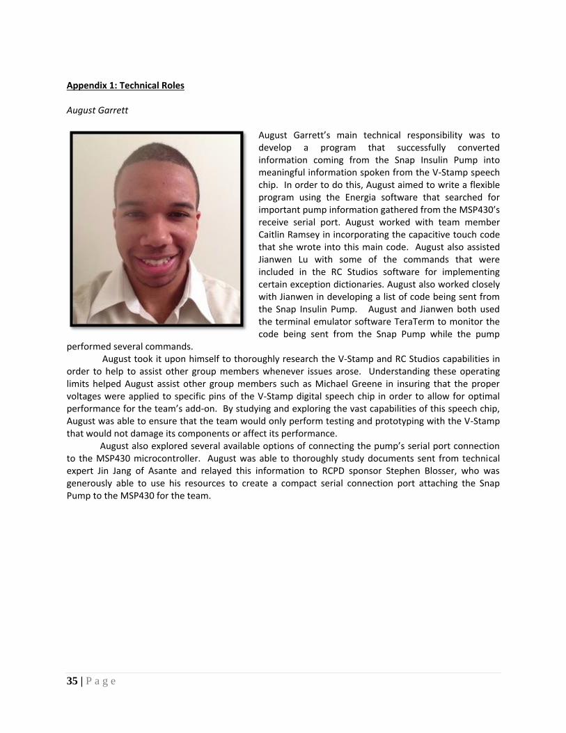
Appendix 1: Technical Roles August Garrett
August Garrett’s main technical responsibility was to develop a program that successfully converted information coming from the Snap Insulin Pump into meaningful information spoken from the V-Stamp speech chip. In order to do this, August aimed to write a flexible program using the Energia software that searched for important pump information gathered from the MSP430’s receive serial port. August worked with team member Caitlin Ramsey in incorporating the capacitive touch code that she wrote into this main code. August also assisted Jianwen Lu with some of the commands that were included in the RC Studios software for implementing certain exception dictionaries. August also worked closely with Jianwen in developing a list of code being sent from the Snap Insulin Pump. August and Jianwen both used the terminal emulator software TeraTerm to monitor the code being sent from the Snap Pump while the pump
performed several commands. August took it upon himself to thoroughly research the V-Stamp and RC Studios capabilities in
order to help to assist other group members whenever issues arose. Understanding these operating limits helped August assist other group members such as Michael Greene in insuring that the proper voltages were applied to specific pins of the V-Stamp digital speech chip in order to allow for optimal performance for the team’s add-on. By studying and exploring the vast capabilities of this speech chip, August was able to ensure that the team would only perform testing and prototyping with the V-Stamp that would not damage its components or affect its performance.
August also explored several available options of connecting the pump’s serial port connection to the MSP430 microcontroller. August was able to thoroughly study documents sent from technical expert Jin Jang of Asante and relayed this information to RCPD sponsor Stephen Blosser, who was generously able to use his resources to create a compact serial connection port attaching the Snap Pump to the MSP430 for the team.
36 | P a g e
Michael Greene
Michael Greene was largely responsible for
investigating and prototyping an effective power
supply unit to provide the necessary 5V and 3.3V to
the microcontroller, V-stamp, serial connection,
and audio components. This specific task included
some setback. The main concern was with
providing enough voltage to each component
without drawing too much current. These setbacks
are detailed further in the power supply section of
this report. Once the final prototype was efficiently
supplying the necessary power to the unit without
quickly dissipating the batteries, the prototype was
then soldered onto a thin breadboard to reduce its
size.
While creating and testing the power supply, Michael also focused his attention towards condensing the individual components in order to
reduce the overall size of the prototype. This was achieved by transferring the original functional V-Stamp circuitry to a second thin breadboard. Additionally, the MSP430 microcontroller was attached to the same breadboard and the pin connections were routed to both the V-Stamp circuitry and the power supply. Upon finalizing the condensed components, Michael was able to aid in the design and creation of the casing unit that would contain them.
Devotion was also spent in helping August and Jianwen investigate the ASCII code being sent to the add-on unit. Using the TeraTerm software program that Asante had provided, an excel sheet was formulated detailing the correlation between the individual screens and their associated ASCII strings. This knowledge was further used to assist in creating the Energia program that reads the incoming ASCII string and links it with an output message to the V-Stamp.
Lastly, time was also spent researching the possibility of implementing haptic touch as a secondary means of feedback response. Different types of actuators and drivers were investigated extensively. Unfortunately, due to time constraints, this idea could not be implemented into the current model. Hopefully, this resulting research can be used for incorporation within future design models.
37 | P a g e
Jianwen Lu
Jianwen’s primary technical role was to program
the V-Stamp digital speech chip. For this project
the team was able to use the V-Stamp chip as a
type of memory device for the add-on. Jianwen
successfully researched how to use the V-Stamp
chip, and how to create several exception
dictionaries in the V-stamp. Jianwen was able to
create an exception dictionary using the software
RC Studios for the V-Stamp, and defined code
coming from the Asante Snap Insulin Pump into
understandable words.
Also, Jianwen worked with team member Caitlin Ramsey by recording all of the most significant words coming from the Snap Pump in Caitlin’s voice. He converted all of the sound files into MP3 format, and compiled them into the memory of the V-Stamp. He also created another exception
dictionary to define all the words that would be spoken with Caitlin’s voice. As a result of doing this, the team was able to get rid of the robotic voice of the V-Stamp’s text-to-speech processor. Before working on the V-Stamp, Jianwen worked with team member August Garrett to determine the exact code coming out from the insulin pump by using the software TeraTerm. By using TeraTerm, Jianwen and August were able to create a list of the main code strings coming from the pump, and figured out that those codes were using ASCII characters. Jianwen then proposed the idea of using the V-Stamp to define these codes. In addition, Jianwen also contributed in researching which microcontroller and digital speech chip the team would be able to use to most successfully complete this project. Jianwen once again collaborated with Caitlin Ramsey during several brainstorming sessions and declared that the team should use the MSP430 Launchpad as a control center, and the V-stamp solely as a memory device and digital speech chip since the MSP430 has more functional processing capabilities than the V-Stamp.
38 | P a g e
Caitlin Ramsey
Caitlin implemented capacitive touch into the
design. The basic idea behind capacitive touch is
there is a system that contains its own
capacitance. When an external object with its
own capacitance, such as a finger, comes near or
touches the system, the capacitance of the
system is changed. Capacitive touch, in the
insulin pump design, allows the user to touch
the button, without pressing it, and hear what
the button’s function is for the current screen.
Using the MSP340 Launchpad and the Capacitive
Touch Library, she created buttons that could
register a change in capacitance. The Capacitive
Touch Library sets designated pins as sensors
and registers the sensors as ‘touched’ once the
capacitance changes a predetermined amount.
In order to implement the design conductive
tape was adhered to the top of the buttons. The tape was connected from the front of the pump to the
back where it could connect with the case holding the MSP430 Launchpad. Electrical tape was put over
the conductive tape, to keep the conductive tape from moving or falling off.
The Energia software platform was used in the programming of the MSP430. Energia is a simpler and sleeker programming language as compared to Code Composer Studio that is associated with the MSP430. The software for the microcontroller was implemented so that for each screen the program would enter a while loop. The ‘while’ loop would continuously check for a change in capacitance for each of the sensors. Once the button was touched, the program would send a signal to the v-stamp with the appropriate function of the button, reset the button and continue checking for a change in capacitance. If the screen changed or the alarm went off, the program would break out of the while loop, send a signal for what is on the screen and move into a different while loop for the new functions of the buttons for the screen.
39 | P a g e
Appendix 2 - References "V Stamp Datasheet." Web. 30 Nov. 2014. <http://www.rcsys.com/Downloads/v-stamp.pdf>. "V-Pod Datasheet." Web. 14 Nov. 2014. <http://www.rcsys.com/Downloads/v-pod.pdf>. "MSP430x2xx Family User's Guide." <i>Www.ti.com</i>. Web. 1 Dec. 2014. <http://www.ti.com/lit/ug/slau144j/slau144j.pdf>. "RC8660 User's Guide." <i>Www.rcsys.com</i>. Web. 21 Nov. 2014. <http://www.rcsys.com/Downloads/rc8660.pdf>. "Reference | Energia." <i>Energia.nu</i>. Web. 25 Nov. 2014. <http://energia.nu/reference/>. "Pololu Adjustable Step-Up/Step-Down Voltage Regulator S8V3A." <i>Pololu Adjustable Step-Up/Step-Down Voltage Regulator S8V3A</i>. Web. 2 Dec. 2014. <http://www.pololu.com/product/2120>. "DRV2605 (ACTIVE)." <i>DRV2605</i>. Web. 28 Nov. 2014. <http://www.ti.com/product/DRV2605/datasheet>. "LM2940 Datasheet." <i>Www.ti.com</i>. Web. 1 Dec. 2014. <http://www.ti.com/lit/ds/symlink/lm2940-n.pdf>. "LM3940 Datasheet." Www.ti.com. Web. 20 Nov. 2014. <http://www.ti.com/lit/ds/symlink/lm3940.pdf>. "About Insulin Pumps." EHow. Demand Media, 05 June 2009. Web. 19 Sept. 2014. "HowStuffWorks "Active, Semi-passive and Passive RFID Tags"" HowStuffWorks. N.p., n.d. Web. 19 Sept. 2014. Infusing Patients Safely: Priority Issues from the AAMI/FDA Infusion Device Summit. Arlington, VA.: AAMI, Association for the Advancement of Medical Instrumentation, 2010. Print. "Text-to-speech with the SpeakJet." Let's Make Robots! N.p., n.d. Web. 19 Sept. 2014. Zhang, Yi, Raoul Jetley, Paul L. Jones, and Arnab Ray. "Abstract." National Center for Biotechnology Information. U.S. National Library of Medicine, 01 Nov. 2011. Web. 19 Sept. 2014.
40 | P a g e
Appendix 3 Energia Code #include <CapTouch.h> // Include Capacitive Touch Library in code in order to set pins as capacitive touch buttons #define BUTTON1 P1_4 // Define pin1 as button1 #define BUTTON2 P1_5 // Define pin2 as button2 #define BUTTON3 P2_0 // Define pin3 as button3 #define BUTTON4 P2_1 // Define pin4 as button4 #define BUTTON5 P2_2 // Define pin5 as button5 byte inByte = 0; // set byte that will read the buffer as zero char hand[] = 'T','U','B','I','N','G'; // set the characters of hand as TUBING, this will detect the ALARM char pump[] = '8','6'; // set the characters of pump to be 86, this will detect the graph screen char legn[] = '8','8'; // set the legn characters to be 88, this will detect the legend screen char man[] = '3','2','7'; // set the man characters to be 327, this will detect the Main Menu screen char basal[] ='B','a','s','a','l'; // set the basal characters to be Basal, this will detect the Basal History screen char bg[] = 'B','G'; // Set the BG history screen to be detected by the characters BG in that order char day[]= 'D','a','i','l','y'; // Set the Daily Totals screen to be detected by the string of characters Daily char avrpt[]='A','v','e'; // Set the Average Report Screen to be detected by the character string Ave char almhis[]='A','l','a','r','m'; // Set the Alarm History screen to be detected by the Alarm character string char bolus[] = 'B','o','l','u'; // set the bolus characters to be Bolu, this will detect the Bolus History Screen char check[]= '3','3','5'; // set the check characters to be 335, this will detect the Check Tubing Connector Screen char cntor[] = '1','2','3','4',',',' '; // set contor characters to be '1234, ', this will detect the Check Tubing Connector screen after the alarm char ending[] = 'S','c','r','e','e','n'; // set the ending characters to be 'Screen', this will detect the screen timeout int messageIndex = 0; // messageIndex will read the length of the string in the buffer CapTouch testbutton1 = CapTouch(BUTTON1, TOUCH_BUTTON); // set button1 as a touch button CapTouch testbutton2 = CapTouch(BUTTON2, TOUCH_BUTTON); // set button 2 as a touch button CapTouch testbutton3 = CapTouch(BUTTON3, TOUCH_BUTTON); // set button 3 as a touch button CapTouch testbutton4 = CapTouch(BUTTON4, TOUCH_BUTTON); // set button 4 as a touch button CapTouch testbutton5 = CapTouch(BUTTON5, TOUCH_BUTTON); // set button 5 as a touch button boolean buttonState1 = false; // set the boolean state of button 1 boolean buttonState2 = false; // set boolean state of button 2 boolean buttonState3 = false; // set boolean state of button 3 boolean buttonState4 = false; // set boolean state of button 4
41 | P a g e
boolean buttonState5 = false; // set boolean state of button 5 void setup() // setup code in this loop, runs only once Serial.begin(115200); // set the baud rate of the serial connection to be 115200, the same as the insulin pump void loop()// this code will run continuously unless the code says to break out of the loop while (Serial.available()>0) // while there is something inside the buffer. If the buffer is empty, the while loop will be ignored inByte = Serial.read(); //Declares the variable "inByte" as whatever the incomming byte from the serial port reads if (inByte == hand[messageIndex]) //compares the variable "inByte" with the position in the "hand" array messageIndex++; //adds one to the messageIndex if the above statement is true if (messageIndex == sizeof(hand)) //compares the messageIndex to the size of the "hand" array messageIndex = 0; //Sets messageIndex to 0 to search for more loops setZero(); //Calls the function to speak the phrase "Alarm" //Note: Remaining loops follow the same principle listed above else if (inByte == pump[messageIndex]) messageIndex++; if (messageIndex == sizeof(pump)) messageIndex = 0; setOne(); else if (inByte == legn[messageIndex]) messageIndex++; if (messageIndex == sizeof(legn)) messageIndex = 0; setTwo();
42 | P a g e
else if (inByte == man[messageIndex]) messageIndex++; if (messageIndex == sizeof(man)) messageIndex = 0; setThree(); else if (inByte == bg[messageIndex]) messageIndex++; if (messageIndex == sizeof(bg)) messageIndex = 0; setFive(); else if (inByte == day[messageIndex]) messageIndex++; if (messageIndex == sizeof(day)) messageIndex = 0; setSix(); else if (inByte == basal[messageIndex]) messageIndex++; if (messageIndex == sizeof(basal)) messageIndex = 0; setFour(); else if (inByte == avrpt[messageIndex]) messageIndex++; if (messageIndex == sizeof(avrpt)) messageIndex = 0;
43 | P a g e
setSeven(); else if (inByte == almhis[messageIndex]) messageIndex++; if (messageIndex == sizeof(almhis)) messageIndex = 0; setEight(); else if (inByte == bolus[messageIndex]) messageIndex++; if (messageIndex == sizeof(bolus)) messageIndex = 0; setNine(); else if (inByte == check[messageIndex]) messageIndex++; if (messageIndex == sizeof(check)) messageIndex = 0; setMonty(); else if (inByte == cntor[messageIndex]) messageIndex++; if (messageIndex == sizeof(cntor)) messageIndex = 0; setEleven(); else if (inByte == ending[messageIndex]) messageIndex++; if (messageIndex == sizeof(ending))
44 | P a g e
messageIndex = 0; setTwelve(); else messageIndex = 0; Serial.flush(); void setZero () Serial.println("ALARM!"); // send ALARM! to the V-stamp while (!Serial.find("1234")) // if the buffer contains 1234 (the next screen), then leave the while loop if (testbutton1.isTouched() > 0) // if the first button is touched (same as the other while loops) if (buttonState1 == false) // and if the button is not in the process of saying what is on the screen (same as the other while loops) buttonState1 = true; // change the if boolean statement to true and do nothing (same as the other while loops) else if (testbutton2.isTouched() > 0) // if the first button is touched if (buttonState2 == false) // and if the button is not in the process of saying what is on the screen buttonState2 = true; // change the if boolean statement to true and do nothing else if (testbutton3.isTouched() > 0) // if the first button is touched if (buttonState3 == false) // and if the button is not in the process of saying what is on the screen buttonState3 = true; // change the if boolean statement to true Serial.println("Silence"); // Say the button function for that screen else if (testbutton4.isTouched() > 0) // if the first button is touched if (buttonState4 == false) // and if the button is not in the process of saying what is on the screen buttonState4 = true; // change the if boolean statement to true and do nothing else if (testbutton5.isTouched() > 0) // if the first button is touched if (buttonState5 == false) // and if the button is not in the process of saying what is on the screen
45 | P a g e
buttonState5 = true; // change the if boolean statement to true and do nothing else // if neither buttons are pressed, change the boolean state so that they reflect that buttonState1 = false; buttonState2 = false; buttonState3 = false; buttonState4 = false; buttonState5 = false; void setOne() Serial.println("Graph"); // say what is one the screen while (!Serial.find("2014") && !Serial.find("KSIM")) // if 2014 or KSIM is found in the buffer, then leave the while loop if (testbutton1.isTouched() > 0) if (buttonState1 == false) buttonState1 = true; Serial.println("Legend"); // say the appropriate function for the button else if (testbutton2.isTouched() > 0) if (buttonState2 == false) buttonState2 = true; else if (testbutton3.isTouched() > 0) if (buttonState3 == false) buttonState3 = true; else if (testbutton4.isTouched() > 0) if (buttonState4 == false) buttonState4 = true; else if (testbutton5.isTouched() > 0) if (buttonState5 == false) buttonState5 = true; Serial.println("Exit"); else buttonState1 = false;
46 | P a g e
buttonState2 = false; buttonState3 = false; buttonState4 = false; buttonState5 = false; void setTwo() Serial.println("Legend"); while (!Serial.find("2014") && !Serial.find("K")) if (testbutton1.isTouched() > 0) if (buttonState1 == false) buttonState1 = true; else if (testbutton2.isTouched() > 0) if (buttonState2 == false) buttonState2 = true; else if (testbutton3.isTouched() > 0) if (buttonState3 == false) buttonState3 = true; else if (testbutton4.isTouched() > 0) if (buttonState4 == false) buttonState4 = true; else if (testbutton5.isTouched() > 0) if (buttonState5 == false) buttonState5 = true; else buttonState1 = false; buttonState2 = false; buttonState3 = false; buttonState4 = false; buttonState5 = false;
47 | P a g e
void setThree() Serial.println("MainMenu"); while (!Serial.find("2014") && !Serial.find("KSIM")) if (testbutton1.isTouched() > 0) if (buttonState1 == false) buttonState1 = true; Serial.println("Graph"); else if (testbutton2.isTouched() > 0) if (buttonState2 == false) buttonState2 = true; Serial.println("Light"); else if (testbutton3.isTouched() > 0) if (buttonState3 == false) buttonState3 = true; else if (testbutton4.isTouched() > 0) if (buttonState4 == false) buttonState4 = true; Serial.println("Exit"); else if (testbutton5.isTouched() > 0) if (buttonState5 == false) buttonState5 = true; Serial.println("Status"); else buttonState1 = false; buttonState2 = false; buttonState3 = false; buttonState4 = false; buttonState5 = false; void setFour() Serial.println("BasalHistory"); while (!Serial.find("2014") && !Serial.find("KSIM"))
48 | P a g e
if (testbutton1.isTouched() > 0) if (buttonState1 == false) buttonState1 = true; Serial.println("Previous"); else if (testbutton2.isTouched() > 0) if (buttonState2 == false) buttonState2 = true; else if (testbutton3.isTouched() > 0) if (buttonState3 == false) buttonState3 = true; Serial.println("Select"); else if (testbutton4.isTouched() > 0) if (buttonState4 == false) buttonState4 = true; Serial.println("Exit"); else if (testbutton5.isTouched() > 0) if (buttonState5 == false) buttonState5 = true; Serial.println("Next"); else buttonState1 = false; buttonState2 = false; buttonState3 = false; buttonState4 = false; buttonState5 = false; void setFive() Serial.println("BGHistory"); while (!Serial.find("2014") && !Serial.find("KSIM")) if (testbutton1.isTouched() > 0) if (buttonState1 == false) buttonState1 = true; Serial.println("Previous");
49 | P a g e
else if (testbutton2.isTouched() > 0) if (buttonState2 == false) buttonState2 = true; else if (testbutton3.isTouched() > 0) if (buttonState3 == false) buttonState3 = true; Serial.println("Select"); else if (testbutton4.isTouched() > 0) if (buttonState4 == false) buttonState4 = true; Serial.println("Exit"); else if (testbutton5.isTouched() > 0) if (buttonState5 == false) buttonState5 = true; Serial.println("Next"); else buttonState1 = false; buttonState2 = false; buttonState3 = false; buttonState4 = false; buttonState5 = false; void setSix() Serial.println("DailyTotals"); while (!Serial.find("2014") && !Serial.find("KSIM")) if (testbutton1.isTouched() > 0) if (buttonState1 == false) buttonState1 = true; Serial.println("Previous"); else if (testbutton2.isTouched() > 0) if (buttonState2 == false) buttonState2 = true;
50 | P a g e
else if (testbutton3.isTouched() > 0) if (buttonState3 == false) buttonState3 = true; Serial.println("Select"); else if (testbutton4.isTouched() > 0) if (buttonState4 == false) buttonState4 = true; Serial.println("Exit"); else if (testbutton5.isTouched() > 0) if (buttonState5 == false) buttonState5 = true; Serial.println("Next"); else buttonState1 = false; buttonState2 = false; buttonState3 = false; buttonState4 = false; buttonState5 = false; void setSeven() Serial.println("AverageReport"); while (!Serial.find("2014") && !Serial.find("KSIM")) if (testbutton1.isTouched() > 0) if (buttonState1 == false) buttonState1 = true; Serial.println("Previous"); else if (testbutton2.isTouched() > 0) if (buttonState2 == false) buttonState2 = true; else if (testbutton3.isTouched() > 0) if (buttonState3 == false) buttonState3 = true; Serial.println("Select");
51 | P a g e
else if (testbutton4.isTouched() > 0) if (buttonState4 == false) buttonState4 = true; Serial.println("Exit"); else if (testbutton5.isTouched() > 0) if (buttonState5 == false) buttonState5 = true; Serial.println("Next"); else buttonState1 = false; buttonState2 = false; buttonState3 = false; buttonState4 = false; buttonState5 = false; void setEight() Serial.println("AlarmHistory"); while (!Serial.find("2014") && !Serial.find("KSIM")) if (testbutton1.isTouched() > 0) if (buttonState1 == false) buttonState1 = true; Serial.println("Previous"); else if (testbutton2.isTouched() > 0) if (buttonState2 == false) buttonState2 = true; else if (testbutton3.isTouched() > 0) if (buttonState3 == false) buttonState3 = true; Serial.println("Select"); else if (testbutton4.isTouched() > 0) if (buttonState4 == false) buttonState4 = true;
52 | P a g e
Serial.println("Exit"); else if (testbutton5.isTouched() > 0) if (buttonState5 == false) buttonState5 = true; Serial.println("Next"); else buttonState1 = false; buttonState2 = false; buttonState3 = false; buttonState4 = false; buttonState5 = false; void setNine() Serial.println("BolusHistory"); while (!Serial.find("2014") && !Serial.find("KSIM")) if (testbutton1.isTouched() > 0) if (buttonState1 == false) buttonState1 = true; Serial.println("Previous"); else if (testbutton2.isTouched() > 0) if (buttonState2 == false) buttonState2 = true; else if (testbutton3.isTouched() > 0) if (buttonState3 == false) buttonState3 = true; Serial.println("Select"); else if (testbutton4.isTouched() > 0) if (buttonState4 == false) buttonState4 = true; Serial.println("Exit");
53 | P a g e
else if (testbutton5.isTouched() > 0) if (buttonState5 == false) buttonState5 = true; Serial.println("Next"); else buttonState1 = false; buttonState2 = false; buttonState3 = false; buttonState4 = false; buttonState5 = false; void setMonty() Serial.println("CheckTubingConnector"); while (!Serial.find("~")) if (testbutton1.isTouched() > 0) if (buttonState1 == false) buttonState1 = true; else if (testbutton2.isTouched() > 0) if (buttonState2 == false) buttonState2 = true; else if (testbutton3.isTouched() > 0) if (buttonState3 == false) buttonState3 = true; else if (testbutton4.isTouched() > 0) if (buttonState4 == false) buttonState4 = true; Serial.println("Exit"); else if (testbutton5.isTouched() > 0) if (buttonState5 == false) buttonState5 = true; Serial.println("Next"); else
54 | P a g e
buttonState1 = false; buttonState2 = false; buttonState3 = false; buttonState4 = false; buttonState5 = false; void setEleven() Serial.println("CheckTubingConnector"); while (!Serial.find("KSIM")) if (testbutton1.isTouched() > 0) if (buttonState1 == false) buttonState1 = true; else if (testbutton2.isTouched() > 0) if (buttonState2 == false) buttonState2 = true; else if (testbutton3.isTouched() > 0) if (buttonState3 == false) buttonState3 = true; Serial.println("OK"); else if (testbutton4.isTouched() > 0) if (buttonState4 == false) buttonState4 = true; else if (testbutton5.isTouched() > 0) if (buttonState5 == false) buttonState5 = true; else buttonState1 = false; buttonState2 = false; buttonState3 = false; buttonState4 = false; buttonState5 = false;
55 | P a g e
void setTwelve() while(!Serial.find("TUBING") && !Serial.find("2014")) // in order to keep the vstamp from saying anything, stay in this while loop while the pump turns itself off
56 | P a g e
Final System Connection Schematic UART Cable Pin Connections