Chapter 6 BLOCK SPREADING FOR MULTIPATH-RESILIENT GENERALIZED MULTI-CARRIER CDMA Zhengdao Wang and Georgios B. Giannakis 1 Dept. of Electrical and Computer Engineering University of Minnesota 200 Union Street SE Minneapolis MN 55455 USA {zhengdao, georgios}@ece.umn.edu The emerging generation of broadband multiple access communication systems will enable dissemination of multimedia information to a large number of geographi- cally dispersed (and possibly mobile) users through integrated wireline-wireless net- works. The increasing demand for Internet services, wireless television and fast ac- cess to large databases pushes the technology towards higher bandwidth and carrier frequencies, while the need for sharing a common air interface to transfer multiple data rates poses a formidable challenge to multiple access communication systems. Code Division Multiple Access (CDMA) systems equipped with reliable multiuser interference (MUI) cancellation have gained worldwide acceptance over competing TDMA and FDMA alternatives, whose capacity is bandwidth limited [17]. With the growing demand for high data rates, it is thus not surprising that, apart from inevitable differences, the proposed standards for third generation mobile systems 1 This research was supported by NSF CCR grant No. 98-05350 and NSF Wireless Initiative Grant No. 99-79443. 219
Transcript
Chapter 6
BLOCK SPREADING FORMULTIPATH-RESILIENT
GENERALIZEDMULTI-CARRIER CDMA
Zhengdao Wang and Georgios B. Giannakis1
Dept. of Electrical and Computer EngineeringUniversity of Minnesota
200 Union Street SEMinneapolis MN 55455
USA{zhengdao, georgios}@ece.umn.edu
The emerging generation of broadband multiple access communication systemswill enable dissemination of multimedia information to a large number of geographi-cally dispersed (and possibly mobile) users through integrated wireline-wireless net-works. The increasing demand for Internet services, wireless television and fast ac-cess to large databases pushes the technology towards higher bandwidth and carrierfrequencies, while the need for sharing a common air interface to transfer multipledata rates poses a formidable challenge to multiple access communication systems.Code Division Multiple Access (CDMA) systems equipped with reliable multiuserinterference (MUI) cancellation have gained worldwide acceptance over competingTDMA and FDMA alternatives, whose capacity is bandwidth limited [17]. Withthe growing demand for high data rates, it is thus not surprising that, apart frominevitable differences, the proposed standards for third generation mobile systems
1This research was supported by NSF CCR grant No. 98-05350 and NSF Wireless InitiativeGrant No. 99-79443.
219
220 Block Spreading for Multipath-Resilient Generalized Multi-Carrier CDMA Chapter 6
in the US, Japan, and Europe are converging to the wideband CDMA approach.MUI is caused by user asynchronism and multipath propagation — two criti-
cal factors that limit performance of mobile wireless CDMA systems because theycause interchip/intersymbol interference (ICI/ISI), destroy orthogonality of usercodes and thus prevent MUI elimination. But once channel status information(CSI) is acquired, the multipath-induced diversity can be exploited advantageouslyif transmission bandwidth is wide enough to resolve different paths in time and com-bine them coherently with a simple RAKE receiver (see e.g., [56]). Although such ascheme has been successful with single user direct sequence (DS) spread spectrum(SS) transmissions, presence of MUI in DS-CDMA perturbs coherent combiningof multipath returns especially when strong nearby users mask weak users located“far-away” (near-far effect) — a cause justifying the considerable amount of re-search devoted to MUI cancellation and multiuser detection (MUD) schemes forCDMA (see e.g., [55] and references therein). Instead of relying on receiver designonly to cope with MUI, joint transmitter-receiver design over multipath channelswas considered in [23,57] for interference suppression in synchronous downlink chan-nels. But even for the downlink, these designs do not guarantee channel-irrespectivesymbol recovery and are suboptimal compared to [42].
Multi-carrier (MC) precoding systems (and in particular Orthogonal FrequencyDivision Multiple Access (OFDMA) systems) [26,38,39,44] are immune to MUI, be-cause different users may use different (sub)carriers. However, symbol recovery forthe uplink multiple access cannot be assured in the presence of multipath. Indeed,OFDMA systems are sensitive to multipath fading: subchannels corresponding tochannel nulls are strongly attenuated and relative performance drops unless consid-erable amount of error correction capability is introduced at the price of reducedbandwidth efficiency. The recognition of complementary capabilities to resist MUIand cope with multipath, has led to recent exciting developments of MC-CDMAalternatives (see e.g., [8] and references therein); however, guaranteed cancellationof MUI and multipath effects in the uplink and the challenges presented by the apriori unknown mobile channel for wireless multimedia transmissions have not beenaddressed and constitute the primary motivation behind the wideband multipleaccess system outlined in this chapter and detailed in [13,15,16], [41], and [60–62].
We introduce first an all-digital filterbank-based multirate Generalized Multi-Carrier (GMC) CDMA model in the general asynchronous multipath scenario andunify and extend existing CDMA schemes including: single-carrier (SC) DS-CDMA[55], multi-carrier (MC) CDMA [28], MC-DS-CDMA [46], and MT-CDMA [54] (Sec-tion 6.1). Next, we focus on quasi-synchronous (QS) GMC-CDMA transmissionsin multipath. Based on the QS multirate model, we derive and evaluate a novelMUI/ISI-resilient GMC-CDMA system, which has low complexity, can incorporatemultirate services at fine rate resolution and with easy rate switching capabilities,and guarantees identification and (even blind) equalization of multiple channels(Section 6.2). Finally, we evaluate performance of the GMC-CDMA system andcompare it with existing schemes, in the presence of multipath (Section 6.3).
Section 6.1. Block Spreading Model 221
6.1 Block Spreading Model
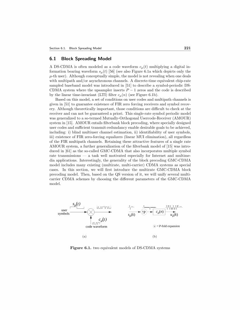
A DS-CDMA is often modeled as a code waveform cµ(t) multiplying a digital in-formation bearing waveform sµ(t) [56] (see also Figure 6.1a which depicts only theµ-th user). Although conceptually simple, the model is not revealing when one dealswith multipath and/or asynchronous channels. A discrete-time equivalent chip-ratesampled baseband model was introduced in [51] to describe a symbol-periodic DS-CDMA system where the upsampler inserts P − 1 zeros and the code is describedby the linear time-invariant (LTI) filter cµ(n) (see Figure 6.1b).
Based on this model, a set of conditions on user codes and multipath channels isgiven in [51] to guarantee existence of FIR zero forcing receivers and symbol recov-ery. Although theoretically important, those conditions are difficult to check at thereceiver and can not be guaranteed a priori. This single-rate symbol periodic modelwas generalized to a so-termed Mutually-Orthogonal Usercode-Receiver (AMOUR)system in [15]. AMOUR entails filterbank block precoding, where specially designeduser codes and sufficient transmit-redundancy enable desirable goals to be achieved,including: i) blind multiuser channel estimation, ii) identifiability of user symbols,iii) existence of FIR zero-forcing equalizers (linear MUI elimination), all regardlessof the FIR multipath channels. Retaining these attractive features of a single rateAMOUR system, a further generalization of the filterbank model of [15] was intro-duced in [61] as the so-called GMC-CDMA that also incorporates multiple symbolrate transmissions — a task well motivated especially for Internet and multime-dia applications. Interestingly, the generality of the block precoding GMC-CDMAmodel includes many existing (multirate, multi-carrier) CDMA systems as specialcases. In this section, we will first introduce the multirate GMC-CDMA blockprecoding model. Then, based on the QS version of it, we will unify several multi-carrier CDMA schemes by choosing the different parameters of the GMC-CDMAmodel.
code waveform
usersymbols
sµ(t)
cµ(t)
(a)
P cµ(n)sµ(k) uµ(k)
P P-fold expansion=
... ...
(b)
Figure 6.1. two equivalent models of DS-CDMA systems
222 Block Spreading for Multipath-Resilient Generalized Multi-Carrier CDMA Chapter 6
6.1.1 Filterbank Block Precoding
We start from the symbol-periodic, single-rate filterbank model Figure 6.1b of [51],where the µth user’s spreading operation is represented by an upsampler followedby an LTI filter whose impulse response is the µth user’s spreading code. Thetransmitted discrete-time signal at the chip rate is
uµ(n) =∞∑
i=−∞sµ(i)cµ(n − iP ), (6.1.1)
where P is the spreading gain and the P -long code satisfies cµ(n) = 0, ∀n 6∈ [0, P−1].With T denoting transpose, let us group the transmitted chip sequence into P -longblocks uµ(i) := [uµ(iP ), . . . , uµ(iP +P −1)], by setting n = iP +p, 0 ≤ p ≤ P −1 in(6.1.1). We also define the column code vector cµ := [cµ(iP ), . . . , cµ(iP +P − 1)]T ,and describe the spreading operation as
uµ(i) = cµsµ(i), (6.1.2)
which shows that the code linearly maps the symbol sµ(i) to the chip block uµ(i).There are many possible ways to generalize the model in (6.1.2). For example,
if we allow the code cµ to be time varying, we can describe long code DS-CDMAsystems (e.g., IS-95 and its derivatives) [44,52,63], and frequency hopping systems[38,63].
Generalizing (6.1.2) to multirate transmissions, one may consider using a differ-ent spreading gain Pµ for different users, or, allocating a different number of Kµ
codes to each user. The former corresponds to Variable Spreading Length (vsl)or variable spreading factor codes, while the latter amounts to what is referred tomulticode (mc) transmissions [24, 34]. In mc-CDMA, high rate users are allocateda large number of codes (large Kµ). The high rate symbol stream is split into Kµ
lower rate substreams, each of which is treated as a virtual user and spread by adifferent (but equally long) code (see Figure 6.2 and Figure 6.3a).
cµ,0(n)
sµ(n) uµ(n)S/P
cµ,Κµ-1(n)
...
Figure 6.2. Multi-code CDMA system
Combination of vsl and mc is also possible: the µth user is then allocatedKµ codes, each having a user dependent length Pµ. Defining the Kµ × 1 sym-bol block sµ(i) := [sµ(iKµ) . . . s(iKµ + Kµ − 1)]T and the Pµ × Kµ code matrixCµ := [cµ,0 · · · cµ,Kµ−1], with cµ,k being the kth allocated Pµ × 1 code vector of
Section 6.1. Block Spreading Model 223
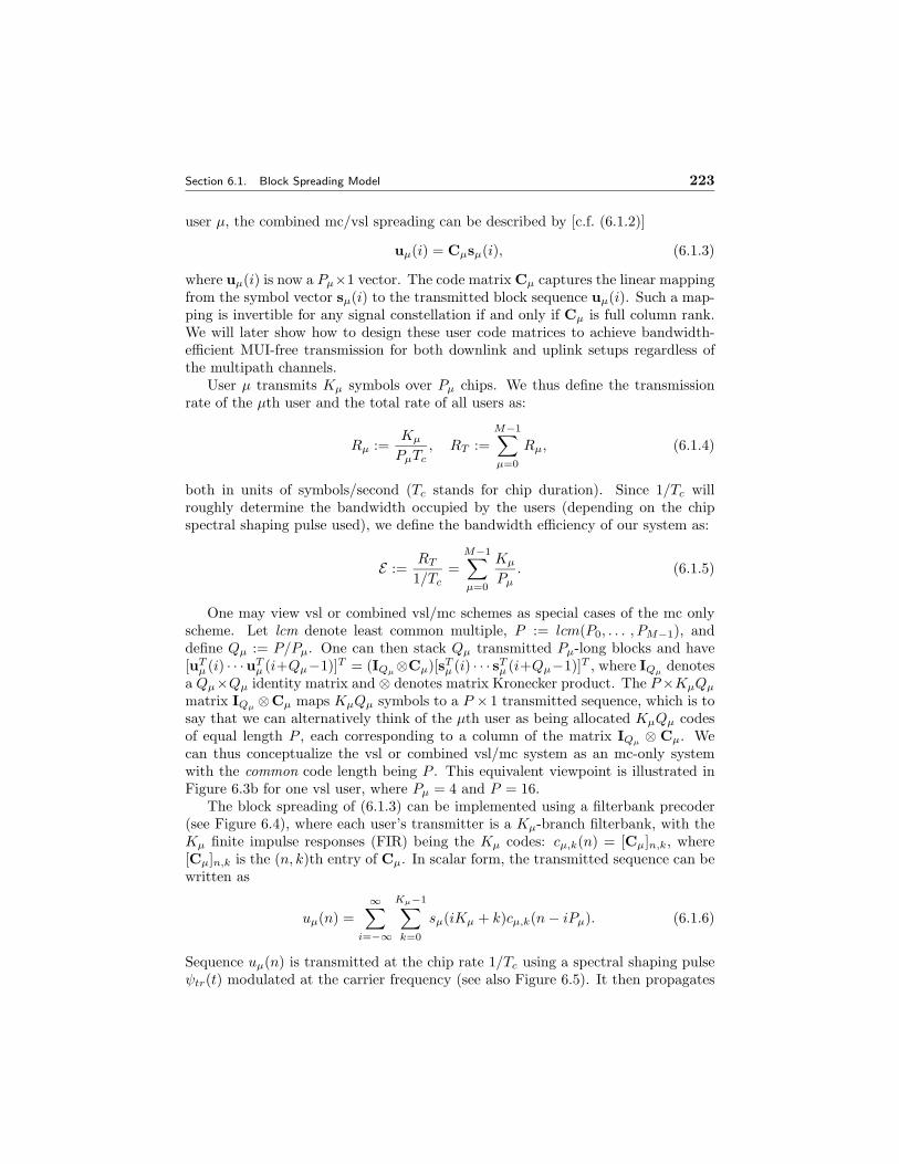
user µ, the combined mc/vsl spreading can be described by [c.f. (6.1.2)]
uµ(i) = Cµsµ(i), (6.1.3)
where uµ(i) is now a Pµ×1 vector. The code matrix Cµ captures the linear mappingfrom the symbol vector sµ(i) to the transmitted block sequence uµ(i). Such a map-ping is invertible for any signal constellation if and only if Cµ is full column rank.We will later show how to design these user code matrices to achieve bandwidth-efficient MUI-free transmission for both downlink and uplink setups regardless ofthe multipath channels.
User µ transmits Kµ symbols over Pµ chips. We thus define the transmissionrate of the µth user and the total rate of all users as:
Rµ :=Kµ
PµTc, RT :=
M−1∑µ=0
Rµ, (6.1.4)
both in units of symbols/second (Tc stands for chip duration). Since 1/Tc willroughly determine the bandwidth occupied by the users (depending on the chipspectral shaping pulse used), we define the bandwidth efficiency of our system as:
E :=RT
1/Tc=
M−1∑µ=0
Kµ
Pµ. (6.1.5)
One may view vsl or combined vsl/mc schemes as special cases of the mc onlyscheme. Let lcm denote least common multiple, P := lcm(P0, . . . , PM−1), anddefine Qµ := P/Pµ. One can then stack Qµ transmitted Pµ-long blocks and have[uT
µ (i) · · ·uTµ (i+Qµ−1)]T = (IQµ
⊗Cµ)[sTµ (i) · · · sT
µ (i+Qµ−1)]T , where IQµdenotes
a Qµ×Qµ identity matrix and ⊗ denotes matrix Kronecker product. The P×KµQµ
matrix IQµ⊗Cµ maps KµQµ symbols to a P × 1 transmitted sequence, which is to
say that we can alternatively think of the µth user as being allocated KµQµ codesof equal length P , each corresponding to a column of the matrix IQµ
⊗ Cµ. Wecan thus conceptualize the vsl or combined vsl/mc system as an mc-only systemwith the common code length being P . This equivalent viewpoint is illustrated inFigure 6.3b for one vsl user, where Pµ = 4 and P = 16.
The block spreading of (6.1.3) can be implemented using a filterbank precoder(see Figure 6.4), where each user’s transmitter is a Kµ-branch filterbank, with theKµ finite impulse responses (FIR) being the Kµ codes: cµ,k(n) = [Cµ]n,k, where[Cµ]n,k is the (n, k)th entry of Cµ. In scalar form, the transmitted sequence can bewritten as
uµ(n) =∞∑
i=−∞
Kµ−1∑k=0
sµ(iKµ + k)cµ,k(n − iPµ). (6.1.6)
Sequence uµ(n) is transmitted at the chip rate 1/Tc using a spectral shaping pulseψtr(t) modulated at the carrier frequency (see also Figure 6.5). It then propagates
224 Block Spreading for Multipath-Resilient Generalized Multi-Carrier CDMA Chapter 6
n
n
n
n
cµ,0(n)
cµ,1(n)
cµ,2(n)
cµ,3(n)
(a)
cµ,0(n)n
n
n
n
cµ,1(n)
cµ,2(n)
cµ,3(n)
(b)
Figure 6.3. Multirate schemes: mc (a) and vsl (b)
through a (perhaps unknown) dispersive channel ψµ,ch(t) and through the receivefilter ψrec(t).
We define hµ(t) to be the overall impulse response of the continuous-time channelincluding the transmitter and receiver filters; i.e., with ? denoting convolution,hµ(t) = ψtr(t) ? ψµ,ch(t) ? ψrec(t). The received baseband signal from user µ isthus given by xµ(t) =
∑∞n=−∞ uµ(n)hµ(t − nTc − τµ), where τµ is the propagation
delay. The overall received signal from all users is therefore: x(t) =∑M−1
µ=0 xµ(t) +ηc(t) ? ψrec(t), where ηc(t) is Additive Gaussian Noise (AGN).
If the RF signal bandwidth is less than or equal to 1/Tc due to spectral shapinglike in IS-95, then the received complex signal envelope with chip-rate sampling willentail no loss of information; otherwise, oversampling can be used. Although ourformulation can be generalized to the oversampling case easily, we only consider
MultiuserReceiver
.
.
.
u0(n)
.
.
.
cM�1;0(n)
c0;K�1(n)
c0;0(n)
hM�1(n)
h0(n)
z
z
.
.
.
.
.
.
z
z
.
.
.
cM�1;K�1(n)
(M � 1)st transmitter
0th transmitter
.
.
.
K0
uM�1(n)
PM�1
PM�1
K0
KM�1
KM�1
sM�1(k)
s0(k)
P0
P0
0th channel
(M-1)st channel
�(n)
sM�1(k)
s0(k)...
x(n)
.
.
.
.
.
.
Figure 6.4. Multi-rate block-precoded CDMA system
Section 6.1. Block Spreading Model 225
chip rate sampling here. At the chip rate, the discrete-time received sequence is
x(n) = x(t)|t=nTc=
M−1∑µ=0
xµ(n) + η(n), (6.1.7)
where: xµ(n) := xµ(t)|t=nTc=
∑∞j=−∞ uµ(j)hµ(n−j), hµ(n) is the sampled version
of the continuous-time impulse response: hµ(n) := hµ(nTc − τµ), and similarly thenoise η(n) := [ηc(t) ? ψrec(t)]|t=nTc
.
Spectral Pulse ChannelReceive-filter
Chipuµ(n)
ψtr(t) ψµ,ch(t) ψrec(t)
ηc(t)xµ(t)
xµ(n)
Figure 6.5. Baseband continuous-time model for user µ, sampled at the chip rate
We denote the order of the channel hµ(l) as Lµ and its Z-transform as Hµ(z).In addition to multipath and the transmit-receive filters, hµ(n) incorporates alsothe µth user’s asynchronism represented by τµ [50,51]. We define L := maxµ Lµ tobe maximum order of all the channels.
Having established our block-precoded multirate transmitter model and thediscrete-time baseband equivalent asynchronous (multipath) channel, we now moveon to the receiver design for such block precoded transmissions.
6.1.2 Asynchronous Multirate Receiver Design
With x(n) as their input, several receiver options are possible (see e.g., [55]): i) ML(maximum likelihood); ii) MF (matched filter); iii) ZF (zero forcing); iv) MMSE(minimum mean square error); v) variations of the above (e.g., adaptive and decisionfeedback (DF) receivers). We focus here on the linear receivers ii)-iv) only.
To allow for asynchronous multirate transmissions through multipath channels,we will consider N consecutive blocks each of P received chips, where N correspondsto the receiver memory expressed in P -long blocks. Over the duration of NPchips, the µth user transmits NP/Pµ = QµN blocks of Kµ symbols: sµ,N :=[sT
µ (0) · · · sTµ (QµN − 1)]T , which are spread first to produce [c.f. (6.1.3)]
uµ,N := [uTµ (0) · · ·uT
µ (QµN − 1)]T = (IQµN ⊗ Cµ)sµ,N . (6.1.8)
After convolving with the FIR channel hµ := [hµ(0), . . . , hµ(L − 1)]T of order Lµ,the block uµ,N will result in a sequence of NP +Lµ chips, the last Lµ of which willextent to the next block of size NP and give rise to Inter-Block Interference (IBI),while the first Lµ chips of the sequence will contain IBI from the previous blockof size NP . The received signal is a superposition of signals from all the users. Ifwe collect sufficiently many (N large) blocks so that NP À L = maxµ(Lµ), the
226 Block Spreading for Multipath-Resilient Generalized Multi-Carrier CDMA Chapter 6
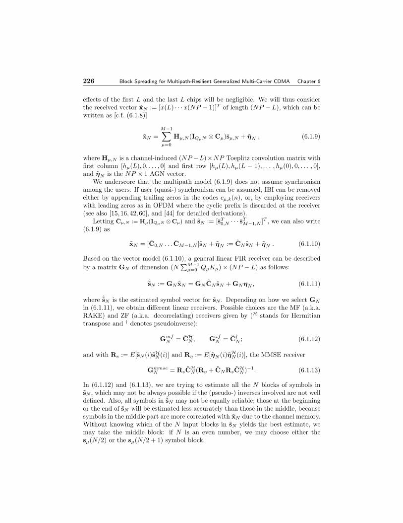
effects of the first L and the last L chips will be negligible. We will thus considerthe received vector xN := [x(L) · · ·x(NP − 1)]T of length (NP − L), which can bewritten as [c.f. (6.1.8)]
xN =M−1∑µ=0
Hµ,N (IQµN ⊗ Cµ)sµ,N + ηN , (6.1.9)
where Hµ,N is a channel-induced (NP −L)×NP Toeplitz convolution matrix withfirst column [hµ(L), 0, . . . , 0] and first row [hµ(L), hµ(L − 1), . . . , hµ(0), 0, . . . , 0],and ηN is the NP × 1 AGN vector.
We underscore that the multipath model (6.1.9) does not assume synchronismamong the users. If user (quasi-) synchronism can be assumed, IBI can be removedeither by appending trailing zeros in the codes cµ,k(n), or, by employing receiverswith leading zeros as in OFDM where the cyclic prefix is discarded at the receiver(see also [15,16,42,60], and [44] for detailed derivations).
Letting Cµ,N := Hµ(IQµN ⊗Cµ) and sN := [sT0,N · · · sT
Based on the vector model (6.1.10), a general linear FIR receiver can be describedby a matrix GN of dimension (N
∑M−1µ=0 QµKµ) × (NP − L) as follows:
ˆsN := GN xN = GNCN sN + GNηN , (6.1.11)
where ˆsN is the estimated symbol vector for sN . Depending on how we select GN
in (6.1.11), we obtain different linear receivers. Possible choices are the MF (a.k.a.RAKE) and ZF (a.k.a. decorrelating) receivers given by (H stands for Hermitiantranspose and † denotes pseudoinverse):
GmfN = CH
N , GzfN = C†
N ; (6.1.12)
and with Rs := E[sN (i)sHN (i)] and Rη := E[ηN (i)ηHN (i)], the MMSE receiver
GmmseN = RsCH
N (Rη + CNRsCHN )−1. (6.1.13)
In (6.1.12) and (6.1.13), we are trying to estimate all the N blocks of symbols insN , which may not be always possible if the (pseudo-) inverses involved are not welldefined. Also, all symbols in ˆsN may not be equally reliable; those at the beginningor the end of sN will be estimated less accurately than those in the middle, becausesymbols in the middle part are more correlated with xN due to the channel memory.Without knowing which of the N input blocks in sN yields the best estimate, wemay take the middle block: if N is an even number, we may choose either thesµ(N/2) or the sµ(N/2 + 1) symbol block.
Section 6.1. Block Spreading Model 227
6.1.3 Quasi-Synchronous Model
Up to now, we have been dealing with asynchronous multipath channels in general.In practice, the users often monitor a common timing reference, e.g., through apilot channel signal. This signal enables what is called QS transmissions, where themobile users attempt to synchronize their transmissions to the common reference,but exact synchronization is difficult to implement (especially when the chip periodis small) in the reverse channel due to multipath and Doppler effects arising becauseof different distances and relative motion. Multi-carrier signaling was proposed in [6]as a means of reducing the synchronization offsets. In general, the users’ signalsmay arrive at the base station offset by a few chips from each other. For thedownlink, the users’ data are transmitted from the base station at the same time– synchronization among users is automatically guaranteed (but multipath is stillpresent). Here we will focus on the uplink scenario, while the downlink will followas a special case of our setup corresponding to hµ(l) = h(l), ∀µ ∈ [0,M − 1].
For reasons mentioned in Section 6.1.1, we assume that Pµ = P from now onand we impose the QS constraint by assuming that:
as1) the FIR channels have maximum order L = L + D < P which incorporatesthe maximum number of discrete-time equivalent taps L, and the maximumdelay D ¿ P that arises due to asynchronism among users. Our P -long codescµ,k(n) have L trailing zeros; i.e., cµ,k(n) = 0 for n 6∈ [0, P − L − 1].
Specifically, the channels are assumed under as1) to be of the form
Hµ(z) :=L∑
l=0
hµ(l)z−l = z−dL∑
l=0
h(l + d)z−l, (6.1.14)
where 0 ≤ d ≤ D. Therefore, each channel can have at most L finite roots perchannel. We will utilize this fact in our design of MUI-free GMC-CDMA in orderto guarantee symbol recovery. Thanks to the L guard chips that we appended in ouruser codes as per as1), there is no IBI between two consecutive P -long blocks (seealso Figure 6.6) in the received block x(i), although MUI and ICI are still present.If the AGN is white and the transmitted symbols are blockwise independent, thereceived blocks of length P will be statistically independent. Assuming knowledgeof the channels, we can design our receiver for such a QS system with memoryN = 1 in (6.1.11), without loss of optimality.
228 Block Spreading for Multipath-Resilient Generalized Multi-Carrier CDMA Chapter 6
Subsequently, we will find it useful to view our QS-CDMA model in the Z-domain. By setting n = iP + p in (6.1.7) and taking into account as1), we re-write(6.1.7) as
x(iP + p) =M−1∑µ=0
Kµ−1∑k=0
sµ(iKµ + k)(cµ,k ? hµ)(p) + η(iP + p). (6.1.15)
Defining X(i; z) :=∑P−1
p=0 x(iP +p)z−p, Cµ,k(z) :=∑Pµ
n=0 cµ,k(n)z−n and N(i; z) :=∑P−1p=0 η(iP + p)z−p, and Z-transforming (6.1.15), we can express the received ith
block in the Z-domain as
X(i; z) =M−1∑µ=0
Kµ−1∑k=0
sµ(iKµ + k)Cµ,k(z)Hµ(z) + N(i; z), ∀i . (6.1.16)
Based on (6.1.16), we will develop in Section 6.2 a GMC-CDMA system that as-sures MUI-free transmissions with guaranteed (even blind, see Section 6.2.3) symbolrecovery regardless of the multipath channels.
For later use, we also give here the vector counterpart of (6.1.16). Taking Qµ = 1and N = 1 in (6.1.10) and defining x(i) := [x(iP ), . . . , x(iP + P − 1)]T , s(i) :=[sT
0 (i) · · · sTM−1(i)]
T , and η(i) = [η(iP ), . . . , η(iP + P − 1)]T , we can write (6.1.10)as (see also Figure 6.7)
x(i) = [H0C0 . . .HM−1CM−1]s(i) + η(i), (6.1.17)
where we have generalized (6.1.10) to a generic ith block instead of the first (i = 0)block only. At the receiver, Gµ and Γµ will be used in Section 6.2 to separate usersand equalize the multipath channels, respectively.
C0 H0 G0 Γ0Γs0(i) u0(i) η(i)η
CM-1 HM-1
sM-1(i) uM-1(i)
...
GM-1 ΓM-1Γ
...
x(i)
x0(i)
xM-1(i)
s0(i)
sM-1(i)
^
^
~
~
... ...
Figure 6.7. Block model for QS block spreading system
6.1.4 All-Digital Unification of Multi-carrier CDMA
We have seen in (6.1.3) and (6.1.17) that our filterbank transmitter performs alinear mapping from blocks of symbols sµ(i) of size Kµ to a transmitted blocksuµ(i) of size Pµ. We will henceforth consider the unifying case of Pµ = P . As weshow next, such a linear mapping model is quite general and encompasses manyexisting CDMA schemes as special cases via proper choices of Cµ.
Section 6.1. Block Spreading Model 229
SC-DS-CDMA: Performance and Identifiability Problems
A single-carrier (SC) symbol-periodic DS-CDMA transmission with processing gainP and spreading code cµ,0 := [cµ(0) · · · cµ(P − 1)]T can be implemented with ourmodel by setting Kµ = K = 1,∀µ, in which case the P × Kµ matrix Cµ in (6.1.3)reduces to the P × 1 symbol-periodic code vector cµ,0 with entries (chips) takenfrom Gold, Walsh-Hadamard, or pseudo-noise (PN) ±1 sequences (c.f. Figure 6.1b).Figure 6.8a shows the Fourier transform (FT) amplitude of a PN code sequence[−1, −1, 1, 1, 1, −1, −1, 1, 1, −1, 1, −1, −1, −1, 1, 1]. As we can see, theamplitude spectrum of the code varies a lot for different (normalized) frequencies.If the channel is time-varying, the received signal to noise ratio (SNR) will also varyfrom very low to high values compared to the mean SNR, depending on how well thechannel transfer function matches the code’s FT. For example, if the user’s channeltransfer function happens to be very small at the peak frequencies of the user codewhere most of the transmitted power is put, the user signal will be considerablyattenuated and hence the receive-SNR will be quite low. If on the other hand thechannel varies slowly compared to the symbol duration, such deep-fading effectsmay span many symbols (roughly the channel coherence time). Interleaving overan interval larger than the channel coherence time combined with error-correctingcodes will lower (and perhaps remove) the bit error rate floor, but certainly atthe price of bandwidth overexpansion and increased complexity. Instead of usingsymbol periodic codes, one may also use long codes, where the code is allowed tovary from symbol to symbol. The code spectrum will then vary from symbol tosymbol, and as a result one user will not suffer persistently from deep fades (seealso [44,63]).
|Cµ,0(f)|
10.50
(a) DS-CDMA
|Cµ(f)|
0.50 1
(b) MC-CDMA
Figure 6.8. Spectra of the DS-CDMA and MC-CDMA codes
In addition to BER performance variability, depending on the codes Cµ andthe channels Hµ, matrix CN in (6.1.10) may not be invertible (or it may be ill-conditioned), which implies that GN in (6.1.11) may not exist (or it may have largenorm causing considerable noise enhancement). It is not widely acknowledged inthe CDMA literature, but there may exist channels for which the user symbols arenot even identifiable from the received signal; i.e., two sets of inputs may producethe same received signal in the absence of noise, making it impossible to decide
230 Block Spreading for Multipath-Resilient Generalized Multi-Carrier CDMA Chapter 6
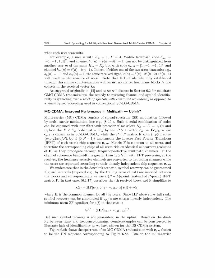
what each user transmits.For example, a user µ with Kµ = 1, P = 4, Walsh-Hadamard code cµ,0 =
[−1 ,−1 , 1 , 1]T , and channel hµ(n) = δ(n)− δ(n− 1) can not be distinguished fromanother user m of the same Km = Kµ but with code cm,0 = [1 ,−1 ,−1 , 1]T andchannel hm(n) = δ(n)+δ(n−1). Indeed, if either one of the two users transmits e.g.,sµ(n) = −1 and sm(n) = 1, the same received signal x(n) = δ(n)−2δ(n−2)+δ(n−4)will result in the absence of noise. Note that lack of identifiability establishedthrough this simple counterexample will persist no matter how many blocks N onecollects in the received vector xN .
As suggested originally in [15] and as we will discuss in Section 6.2 for multirateGMC-CDMA transmissions, the remedy to restoring channel and symbol identifia-bility is spreading over a block of symbols with controlled redundancy as opposed toa single symbol spreading used in conventional SC-DS-CDMA.
MC-CDMA: Improved Performance in Multipath — Uplink?
Multi-carrier (MC) CDMA consists of spread-spectrum (SS) modulation followedby multi-carrier modulation (see e.g., [8, 19]). Such a serial combination of codescan be captured with our filterbank precoder if we select Kµ = K = 1,∀µ andreplace the P × Kµ code matrix Cµ by the P × 1 vector cµ := Fcµ,0, wherecµ,0 is chosen as in SC-DS-CDMA, while the P × P matrix F with (i, p)th entry{exp(j2πip/P ), i, p ∈ [0, P − 1]} implements the Inverse Fast Fourier Transform(IFFT) of each user’s chip sequence cµ,0. Matrix F is common to all users, andtherefore the corresponding chips of all users ride on identical subcarriers (columnsof F) as they propagate through frequency-selective multipath channels. If thechannel coherence bandwidth is greater than 1/(PTc), with FFT processing at thereceiver, the frequency-selective channels are converted to flat fading channels whilethe users are separated according to their linearly independent chip sequences cµ,0.
We underscore that in the downlink scenario, symbol recovery can be guaranteedif guard intervals (imposed e.g., by the trailing zeros of as1) are inserted betweenthe blocks and correspondingly we use a (P − L)-point (instead of P -point) IFFTmatrix F. In that case, (6.1.17) describes the ith received block and it simplifies to
x(i) = HF[c0,0 c1,0 · · · cM−1,0] s(i) + η(i),
where H is the common channel for all the users. Since HF always has full rank,symbol recovery can be guaranteed if cµ,0’s are chosen linearly independent. Theminimum-norm ZF equalizer for s(i) in that case is
Gzf = (HF[c0,0 · · · cM−1,0])†.
But such symbol recovery is not guaranteed in the uplink. Based on the dual-ity between time- and frequency-domains, counterexamples can be constructed toillustrate lack of identifiability as we have shown for the DS-CDMA system.
Figure 6.8b shows the spectrum of an MC-CDMA transmission with cµ,0 chosento be the PN sequence corresponding to Figure 6.8a. Due to the multi-carrier
Section 6.1. Block Spreading Model 231
modulation (IFFT operation), the DS chips (entries of cµ,0) appear as subcarrieramplitudes in the MC-CDMA spectrum of Figure 6.8b. If the PN sequence hasconstant amplitude (e.g., if it is binary ±1 as in Figure 6.1), the code spectrum willhave equal amplitude at all subcarriers, in contrast to the uneven spectrum of a DS-CDMA transmission. Such a flat distribution of energy over the available frequencybandwidth will result in less variation of the received SNR due to multipath channelson the average (taken over all possible channels if the channels are modeled asrandom, or, over time if the channels are modeled as deterministic but time varying).Based on this observation, we may expect better performance with MC-CDMA thanDS-CDMA in frequency-selective channels, as has been testified in [18].
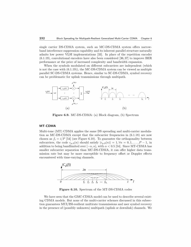
MC-DS-CDMA: DS-CDMA on multiple carriers
In multi-carrier direct-sequence (MC-DS) CDMA systems, each user’s symbolssµ(n) are first serial-to-parallel converted into Nc substreams {sµ,k(n)}Nc−1
k=0 , andeach substream is spread with a common user-dependent P -long DS code cµ,0 hav-ing spectral support (bandwidth normalized by the sampling rate) over [−α, α],where α < 0.5. The spread substreams sµ,k(n)cµ,0 are then modulated on Nc sub-carriers {fi}Nc−1
i=0 with subcarrier spacing 4fi ≤ α [19, 46] (see also Figure 6.9).Smaller spacing increases bandwidth efficiency but also inter-carrier interferencebecause the overlap between successive subcarrier bands increases.
To implement MC-DS-CDMA using our all-digital filterbank precoding model,we first observe that the order of DS spreading and subcarrier modulation can beinterchanged. Specifically, we let the symbols modulate the Nc subcarriers first andthen spread each subcarrier-modulated symbol by the DS sequence cµ,0. ChoosingKµ = Nc = K, ∀µ, we can describe the transmitted signal as
uµ(i) = Cµsµ(i) = diag(cµ,0)FNcsµ(i), (6.1.18)
where: FNcis a P × Nc matrix with (p + 1, k + 1)st entry exp(j2πfkp), which
performs the subcarrier modulation; and, diag(cµ,0) is a diagonal matrix with thepth diagonal entry cµ,0(p). Since the kth column of Cµ is just the spreading codemultiplied by a complex exponential sequence, its DTFT (discrete-time FT) willbe the DTFT of the spreading code shifted by fk, which places a DS-CDMA signalonto the kth subcarrier. MC-DS-CDMA “splits the bandwidth in Nc pieces andperforms DS-CDMA on each piece”. But the signals on different subcarriers canoverlap to some extent in order to save bandwidth. Different subcarrier overlappingratios can be achieved by appropriately choosing the subcarriers fk in order tobalance between bandwidth efficiency and BER performance [46].
If instead of S/P blocking, we perform symbol repetition as in
sµ(i) = [1, 1, . . . , 1]T sµ(i), (6.1.19)
the symbol sµ(i) will be modulated (repeated) on all Nc subcarriers which yieldsthe special MC-DS-CDMA system analyzed in [28]. As opposed to a wideband
232 Block Spreading for Multipath-Resilient Generalized Multi-Carrier CDMA Chapter 6
single carrier DS-CDMA system, such an MC-DS-CDMA system offers narrow-band interference suppression capability and its inherent parallel structure naturallyadmits low power VLSI implementations [33]. In place of the repetition encoder(6.1.19), convolutional encoders have also been considered [36,37] to improve BERperformance at the price of increased complexity and bandwidth expansion.
When the symbols modulated on different subcarriers are independent (whichis not the case with (6.1.19)), the MC-DS-CDMA system can be viewed as multipleparallel SC-DS-CDMA systems. Hence, similar to SC-DS-CDMA, symbol recoverycan be problematic for uplink transmissions through multipath.
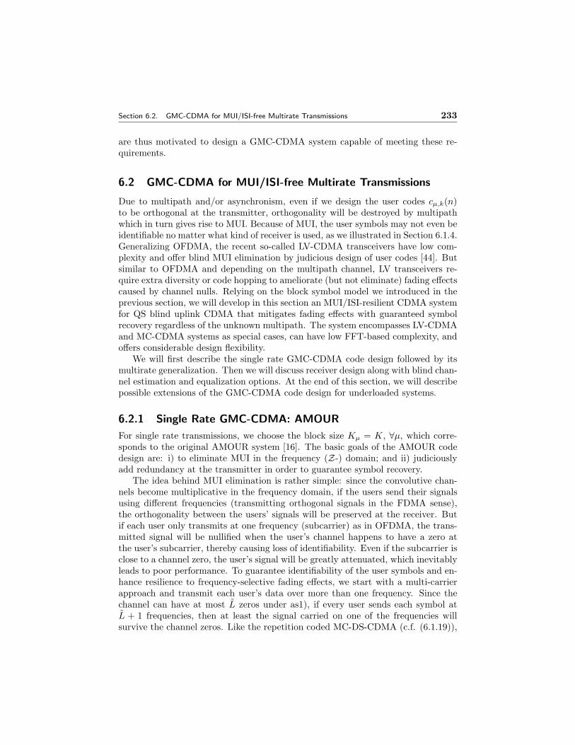
Multi-tone (MT) CDMA applies the same DS spreading and multi-carrier modula-tion as MC-DS-CDMA except that the subcarrier frequencies in (6.1.18) are nowchosen as fi = i/P [54] (see Figure 6.10). To guarantee the orthogonality betweensubcarriers, the code cµ,0(n) should satisfy |cµ,0(n)| = 1,∀n = 0, 1, . . . , P − 1, inaddition to being bandlimited over [−α, α], with α < 0.5 [54]. Since MT-CDMA hassmaller subcarrier separation than MC-DS-CDMA, it can offer higher data trans-mission rate but may be more susceptible to frequency offset or Doppler effectsencountered with time-varying channels.
0 fNcf4f3f2f1
2α
1/P
1 f
|Cµ(f)|
...
Figure 6.10. Spectrum of the MT-DS-CDMA codes
We have seen that the GMC-CDMA model can be used to describe several exist-ing CDMA models. But none of the multi-carrier schemes discussed in this subsec-tion guarantees MUI/ISI-resilient multirate transmissions and user symbol recoveryin the presence of (possibly unknown) multipath (uplink or downlink) channels. We
Section 6.2. GMC-CDMA for MUI/ISI-free Multirate Transmissions 233
are thus motivated to design a GMC-CDMA system capable of meeting these re-quirements.
6.2 GMC-CDMA for MUI/ISI-free Multirate Transmissions
Due to multipath and/or asynchronism, even if we design the user codes cµ,k(n)to be orthogonal at the transmitter, orthogonality will be destroyed by multipathwhich in turn gives rise to MUI. Because of MUI, the user symbols may not even beidentifiable no matter what kind of receiver is used, as we illustrated in Section 6.1.4.Generalizing OFDMA, the recent so-called LV-CDMA transceivers have low com-plexity and offer blind MUI elimination by judicious design of user codes [44]. Butsimilar to OFDMA and depending on the multipath channel, LV transceivers re-quire extra diversity or code hopping to ameliorate (but not eliminate) fading effectscaused by channel nulls. Relying on the block symbol model we introduced in theprevious section, we will develop in this section an MUI/ISI-resilient CDMA systemfor QS blind uplink CDMA that mitigates fading effects with guaranteed symbolrecovery regardless of the unknown multipath. The system encompasses LV-CDMAand MC-CDMA systems as special cases, can have low FFT-based complexity, andoffers considerable design flexibility.
We will first describe the single rate GMC-CDMA code design followed by itsmultirate generalization. Then we will discuss receiver design along with blind chan-nel estimation and equalization options. At the end of this section, we will describepossible extensions of the GMC-CDMA code design for underloaded systems.
6.2.1 Single Rate GMC-CDMA: AMOUR
For single rate transmissions, we choose the block size Kµ = K, ∀µ, which corre-sponds to the original AMOUR system [16]. The basic goals of the AMOUR codedesign are: i) to eliminate MUI in the frequency (Z-) domain; and ii) judiciouslyadd redundancy at the transmitter in order to guarantee symbol recovery.
The idea behind MUI elimination is rather simple: since the convolutive chan-nels become multiplicative in the frequency domain, if the users send their signalsusing different frequencies (transmitting orthogonal signals in the FDMA sense),the orthogonality between the users’ signals will be preserved at the receiver. Butif each user only transmits at one frequency (subcarrier) as in OFDMA, the trans-mitted signal will be nullified when the user’s channel happens to have a zero atthe user’s subcarrier, thereby causing loss of identifiability. Even if the subcarrier isclose to a channel zero, the user’s signal will be greatly attenuated, which inevitablyleads to poor performance. To guarantee identifiability of the user symbols and en-hance resilience to frequency-selective fading effects, we start with a multi-carrierapproach and transmit each user’s data over more than one frequency. Since thechannel can have at most L zeros under as1), if every user sends each symbol atL + 1 frequencies, then at least the signal carried on one of the frequencies willsurvive the channel zeros. Like the repetition coded MC-DS-CDMA (c.f. (6.1.19)),
234 Block Spreading for Multipath-Resilient Generalized Multi-Carrier CDMA Chapter 6
the price paid is bandwidth overexpansion: we need L times larger bandwidth thanthe OFDMA system. To overcome this bandwidth overexpansion, we transmit Ksymbols together using K + L frequencies with K À L, so that the bandwidthexpansion factor (K + L)/K can be brought arbitrarily close to 1. If we succeedin designing the code so that the K symbols can be recovered from any of the Ksubcarriers, then symbol identifiability will also be guaranteed because at most Lof the K + L subcarriers can be nullified by the channel.
In the sequel, we will formulate the aforementioned idea mathematically usingour model (6.1.16) and (6.1.17). To allow for more flexibility, we consider generalfrequencies on the Z-plane instead of those frequencies on the unit circle only. Toavoid confusion, we call the complex frequencies or subcarriers of each user as theuser’s signature points.
Design Principles
To separate users (eliminate MUI) in the Z-domain, let us consider (6.1.16). Sup-pose that at a certain point z = ρ, we have Cµ,k(z)
∣∣z=ρ
= αδm,µ, where α is somenon-zero constant and δm,µ is the Kronecker delta function. Then, X(i; z)
∣∣z=ρ
willcontain only the mth user’s signal and no MUI. Such a point ρ will be one of thesignature points of user m. In general, we seek to build the users’ code polynomialsCµ,k(z) specified by distinct sets of signature points on the complex plane. LetFµ := {ρµ,j ∈ C}J
j=1 be the set of J (a design parameter) signature points of userµ, where C denotes the complex field. We choose ρµ,j so that Fµ
⋂Fm = ∅, forµ 6= m. The set F =
⋃M−1µ=0 Fµ will be termed from now on the system’s set of
signature points. It is then possible to construct codes such that ∀k and ∀j, [15]
Cµ,k(ρm,j) =
{0 if µ 6= m,
Aµθµ,k,j if µ = m,(6.2.1)
where θµ,k,j are non-zero constants up to the designer’s choice, and the amplitudeAµ controls the µth user’s transmitted power. With code designed in (6.2.1), therewill MJ points on the Z-domain such that at each points, only signal from oneuser, the owner of that (signature) point, is present. That way, the MUI can beeliminated in the Z-domain. Energy allocation among one user’s J signature pointswill be determined by the θµ,k,j parameters in (6.2.1).
The minimal order of a polynomial Cµ,k(z) satisfying (6.2.1) is MJ−1, in whichcase Cµ,k(z) can be found using Lagrange interpolation as
Cµ,k(z) = Aµ
J−1∑λ=0
θµ,k,λ
M−1∏m=0
J−1∏j=0
(m,j) 6=(µ,λ)
1 − ρm,jz−1
1 − ρm,jρ−1µ,λ
. (6.2.2)
Now we proceed to show that codes (6.2.2) can achieve MUI-free transmissionand also to find conditions on θµ,j,k that guarantee symbol recovery. Let us de-fine the D × 1 Vandermonde vector vD(ρ) built from the complex frequency ρ as:
Section 6.2. GMC-CDMA for MUI/ISI-free Multirate Transmissions 235
vD(ρ) := [1 ρ−1 . . . ρ−D+1]T . With z replacing ρ and P instead of D, this Vander-monde vector describes the Z-transform in the sense that X(i; z) := vT
P (z)x(i). Wethen define the µth user’s MUI eliminating matrix as (see also Figure 6.7)
Gµ := [vP (ρµ,0) · · ·vP (ρµ,J−1)]T . (6.2.3)
When multiplying x(i) from the left, matrix Gµ maps x(i) to preselected values ofits Z-transform xµ(i) := Gµx(i) = [X(i; ρµ,0) . . . X(i; ρµ,J−1)]T . Plugging z = ρµ,j
into (6.1.16) and using (6.2.1), we can express xµ(i) as
xµ(i) = AµDHµΘµsµ(i) + ηµ(i), (6.2.4)
where DHµ:= diag[Hµ(ρµ,0), . . . ,Hµ(ρµ,J−1)] denotes a J×J diagonal matrix with
diagonal entries Hµ(ρµ,j), Θµ is a J×K matrix with its (j, k)th entry θµ,j,k and thenoise term ηµ(i) := [N(i; ρµ,0), . . . , N(i; ρµ,J−1)]T . Eq. (6.2.4) shows that with thedesign (6.2.1) we can achieve MUI elimination on each user’s J signature points. Toguarantee symbol identifiability from these J points, we choose J ≥ K and deducefrom (6.2.4) that a necessary and sufficient condition to guarantee identifiability ofsymbols sµ(i) from xµ(i) regardless of the input symbol constellation is:
rank(DHµΘµ) ≥ K . (6.2.5)
MUI- and ISI-free symbol recovery follows by applying an equalizer Γµ on x(i)(detailed in Section 6.2.3 and depicted in Figure 6.7). When it comes to satisfying(6.2.5), four possibilities arise:
• Case 1) if the µth transmitter has access to channel status information (CSI),namely Hµ(z), we can always choose J = K distinct points ρµ,j so thatHµ(ρµ,j) 6= 0 ∀j ∈ [0,K − 1], and with any non-singular K × K matrix Θµ,we can fulfill (6.2.5).
• Case 2) if CSI is not available at the transmitters but is available at thereceivers (for example through training). Since Hµ(z) has at most L zeros, inorder to satisfy (6.2.5), we need:
2a) J ≥ L + K; and2b) any J − L rows of Θµ to span the complex space of K-tuples CK .
• Case 3) if CSI is neither available at transmitter nor at the receiver, to re-cover the symbols blindly (without training), we need to somehow estimatethe channels from the MUI-free data xµ(i) in (6.2.15). To guarantee blindidentifiability up to a scalar constant of the multipath channels, we need:
3a) J ≥ L + K; and3b) any K rows of Θµ to span the complex space of K-tuples.
Blind channel estimation for case 3b) will be presented in Section 6.2.3.
• Case 4) if instead of deterministic (as in Cases 1–3) the channel taps and thusHµ(ρµ,j)’s are modeled as random (e.g., Rayleigh or Rician), then selecting
236 Block Spreading for Multipath-Resilient Generalized Multi-Carrier CDMA Chapter 6
J = K + L < K + L increases the probability of satisfying (6.2.5) comparedto the case J = K even with a small number L ¿ L of redundant signaturepoints. We will elaborate further on this case in Remark 2 and Test Case 2that entails Rayleigh fading channels.
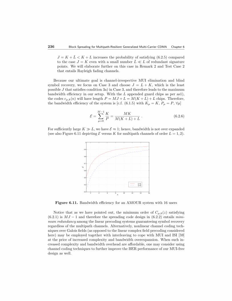
Because our ultimate goal is channel-irrespective MUI elimination and blindsymbol recovery, we focus on Case 3 and choose J = L + K, which is the leastpossible J that satisfies condition 3a) in Case 3, and therefore leads to the maximumbandwidth efficiency in our setup. With the L appended guard chips as per as1),the codes cµ,k(n) will have length P = MJ + L = M(K + L) + L chips. Therefore,the bandwidth efficiency of the system is [c.f. (6.1.5) with Kµ = K, Pµ = P , ∀µ]
E =M−1∑µ=0
K
P=
MK
M(K + L) + L. (6.2.6)
For sufficiently large K À L, we have E ≈ 1; hence, bandwidth is not over expanded(see also Figure 6.11 depicting E versus K for multipath channels of order L = 1, 2).
2 4 6 8 10 12 14 160.3
0.4
0.5
0.6
0.7
0.8
0.9
1
K
L=1L=2
E
Figure 6.11. Bandwidth efficiency for an AMOUR system with 16 users
Notice that as we have pointed out, the minimum order of Cµ,k(z) satisfying(6.2.1) is MJ − 1 and therefore the spreading code design in (6.2.2) entails mini-mum redundancy among the linear precoding systems guaranteeing symbol recoveryregardless of the multipath channels. Alternatively, nonlinear channel coding tech-niques over Galois fields (as opposed to the linear complex field precoding consideredhere) may be employed together with interleaving to cope with MUI and ISI [59]at the price of increased complexity and bandwidth overexpansion. When such in-creased complexity and bandwidth overhead are affordable, one may consider usingchannel coding techniques to further improve the BER performance of our MUI-freedesign as well.
Section 6.2. GMC-CDMA for MUI/ISI-free Multirate Transmissions 237
With J = L + K, condition 3b) translates to requiring any K rows of Θµ to belinearly independent. This is satisfied for example when
Θµ := [vK(ρµ,0) · · ·vK(ρµ,L+K−1)]T , (6.2.7)
where the points {ρµ,j}L+K−1j=0 are distinct so that the Vandermonde matrix Θµ in
(6.2.7) is full rank.Premultiplying sµ(i) by Θµ evaluates the Z-transform of sµ(i) and the signal
component in xµ(i) in (6.2.4) is the product of the µth channel’s transfer functionwith the Z-transform of sµ(i), evaluated at the J signature points. Since multiply-ing two sequences’ Z-transforms amounts to convolving the two sequences in thetime domain, we can recover the linear convolution of sµ(i) with hµ by premultiply-ing xµ(i) by a matrix V−1
µ := [vL+K(ρµ,0), . . . ,vL+K(ρµ,L+K−1)]−T . The lattereffectively performs the inverse Z-transform:
xµ(i) := V−1µ x(i) = AµHµsµ(i) + ηµ(i), (6.2.8)
where Hµ is a (K +L)×K convolution matrix with the first column [hTµ , 0, . . . , 0]T
and the first row [hµ(0), 0, . . . , 0], and ηµ(i) := V−1µ ηµ(i).
H0
s0(i)
...
x0(i)A0
η0(i)η
HM-1
sM-1(i) xM-1(i)
ηΜ−1(i)η
...
AM-1
Figure 6.12. Equivalent parallel AMOUR-CDMA system
Note that (6.2.8) reveals another important feature of our design: namely thatAMOUR converts the multiuser CDMA system into M parallel single-user systemsregardless of the underlying multipath channels (see also Figure 6.12). Thanks tothe redundancy introduced at the transmitter, matrix Hµ is always full rank. Thisproperty can be exploited to construct single user blind equalizers [15,16], e.g., thezero-forcing one: Γzf
µ = H†µV
−1µ . In Section 6.2.3, we are also going to design a
blind equalization algorithm for the general case of (6.2.5).We summarize the AMOUR code design procedure with Θµ as in (6.2.7) in
Algorithm 6.1 and the basic results on the single rate AMOUR system in Theorem 1.
Theorem 1 (single-rate AMOUR) [16]: Under as1) and for a given L = L + D,choose user code polynomials Cµ,k(z) with length P = MJ + L, where J = K + L.
238 Block Spreading for Multipath-Resilient Generalized Multi-Carrier CDMA Chapter 6
Algorithm 6.1 AMOUR System Design StepsS1) Choose the symbol block length K À L;
S2) Select M(L + K) distinct points ρµ,j on the complex plane and assign L + Kof them {ρµ,j}L+K−1
j=0 to be signatures of the µth user;
S3) Compute the codes Cµ,k according to (6.2.2), and add L trailing zeros. Trans-mit the block spread sequence uµ(i) = Cµsµ(i);
S4) Construct the MUI eliminating receive filters Gµ according to (6.2.3) andeliminate MUI using Gµ to obtain xµ(i) as in (6.2.4);
S5) Apply single user equalizer Γµ on the vector xµ(i) to recover sµ(i).
For a prescribed bandwidth efficiency E ∈ (0, 1), select symbol blocking of sizeK = L(1 + 1/M)E/(1− E). Mutually orthogonal user codes Cµ having correspond-ing polynomials obeying (6.2.1) with appropriately chosen θµ,k,j, and zero-forcingreceivers Gzf
µ (c.f. (6.1.11)) then exist that eliminate MUI and ISI determinis-tically regardless of the (possibly unknown) multipath channels hµ(n). Transmitredundancy enables (even blind, see Section 6.2.3) channel estimation independentof the symbol constellation used and the location of channel zeros.
It also turns out that the AMOUR system design Algorithm 6.1 has a niceinterpretation in terms of polynomial division. We detail this interpretation inAppendix 6.4 for interested readers.
Low Complexity Designs
Now let us look into specific choices for the signature points in (6.2.1) that lead toreduced-complexity designs. Suppose ρµ,j ’s are chosen regularly around the unitcircle; e.g.,
ρµ,j ∈ Fµ := {ej2π(µ+jM)M(L+K) }L+K−1
j=0 , µ ∈ [0, . . . ,M − 1]. (6.2.9)
With such signature points and Θµ as in (6.2.7), one can compute the user codesas
cµ,k(n) =
{Aµej 2πµ
M q if n = q(L + K) + k, q = 0 . . . M − 1,
0 otherwise.(6.2.10)
Observe that for every user µ, the code cµ,k(n) = cµ,0(n − k) ∀k = 0, . . . , K − 1,which means that at the transmitter, the spread chip sequence uµ(n) in (6.1.6) isbasically a convolution of sµ(iK+k) with cµ,0(n). But since cµ,0(n) is non-zero onlyat multiples of L+K, this convolution entails a simple shift and scaling only. Hence,with codes as in (6.2.10) the transmitter in AMOUR has very low complexity. At
Section 6.2. GMC-CDMA for MUI/ISI-free Multirate Transmissions 239
the receiver, matrix multiplications (by Gµ and V−1µ ) can be replaced by FFTs.
Algorithmically, the receiver computes a P -point FFT of the received block x(i)at the M(L + K) frequencies given by the system signature points F =
⋃M−1µ=0 Fµ.
Then for each of the M users, the receiver computes an (L + K)-point IFFT atthe L + K frequency samples xµ(i) corresponding to the user’s signature points toobtain xµ(i), upon which any single user equalizer Γµ can be applied.
The codes in (6.2.10) bring out a tradeoff that appears with AMOUR’s selectionof the block size K. On the one hand, one wants to have K large to reduce redundantoverhead needed per block, or, equivalently to avoid bandwidth over expansion[c.f. (6.2.6)]. On the other hand, as K increases, the block gets longer and thedecoding delay increases proportionally and also the channels are required to remaintime-invariant over a longer period. Moreover, when one transmits more symbolsper block, the peak-to-average power in general will increase and power amplifiersmay have to increase their back-offs. From a power-efficiency viewpoint, the codesin (6.2.10) are particularly appealing because they have constant modulus exceptfor the zero-guard intervals during which nothing is transmitted.
Now, let us illustrate the basic idea of AMOUR design and its MUI eliminatingability with a simple example involving the user codes of (6.2.10).
Example Suppose L = 1 and M = 2. For simplicity, we choose K = 2 (re-call that K should be much greater than L to avoid bandwidth overexpansion).The signature points of the two users are shown in Figure 6.13a equally spacedand interleaved around the unit circle; i.e., ρµ,l = exp(j2π(µ + 3l)/6), µ = 0, 1,l = 0, 1, 2. Assuming Aµ = 1, the user codes can be computed from (6.2.2)to be C0,k(z) = 0.5(1 + z−3)z−k, C1,k(z) = 0.5(1 − z−3)z−k, k = 0, 1. In Fig-ure 6.13b, we show the FT magnitude of the codes. In close accordance with thesignature point allocation, their spectra are interleaved and overlapped. We as-sume the blocks (each of length K = 2) sent by the two users are S0(i; z) = 1+z−1,S1(i; z) = 1 − z−1 and the discrete-time equivalent baseband channels are cho-sen to be H0(i; z) = 1 − jz−1, H1(i; z) = 1 + (0.5 + 0.5j)z−1, whose nulls areplotted in Figure 6.13c. The ith noiseless received block then turns out to bex(i) = [1, 0.25 − 0.25j,−0.25 − 0.75j, 0, 0.75 − 0.75j, 0.25 − 0.25j, 0, 0], whose FTmagnitude is depicted in Figure 6.13d with thick line. The corresponding re-ceived spectra of the two users are also shown in the same figure with thin lines.We use circles on the composite curve to denote frequencies that correspond tothe first user’s signature points and hence are free of MUI. Let us now test ourmodulation-independent symbol recovery. Applying the V−1
µ Gµ operator on x(i)for µ = 0, 1, respectively, we obtain Y0(i; z) = 1 + (1 − j)z−1 − jz−2 andY1(i; z) = 1 + (−0.5 + 0.5j)z−1 − (0.5 + 0.5)z−2, which are precisely the convo-lutions of the transmitted block symbols with the corresponding channel impulseresponses of each user, confirming also the equivalent model shown in Figure 6.12.2
240 Block Spreading for Multipath-Resilient Generalized Multi-Carrier CDMA Chapter 6
−1.5 −1 −0.5 0 0.5 1 1.5−1.5
−1
−0.5
0
0.5
1
1.5
Re{z}
Im{z
}
user 0user 1user 2
(a) The users’ signaturepoints
−π −0.5π 0 0.5π π0
0.5
1
1.5
θ
Am
plit
ud
e
user 0user 1
(b) The users’ codes infrequency domain
−1.5 −1 −0.5 0 0.5 1 1.5−1.5
−1
−0.5
0
0.5
1
1.5
−> user 0’s channel null −> user 1’s channel null −> user 2’s channel null
Re{z}
Im{z
}
(c) Channels’ nulls
−π −0.5π 0 0.5π π0
0.5
1
1.5
2
2.5
− sig. roots of user 0: NO MUI
Am
plit
ud
e
θ
from user 0 from user 1 from user 2 composite
(d) FT amplitudes of thereceived noiseless block
Figure 6.13. Example AMOUR system with unit circle signature points
where Fµ is a K × K matrix with (n, k)th entry fµ,k(n), n, k = 0, . . . , K − 1.The vector model for such a choice is shown in Figure 6.14. When channel esti-mates of Hµ(z) are available, e.g., via a feedback channel as in CATV and DSLapplications, such a modification offers additional flexibility in optimizing Fµ andΓµ. Possible optimization criteria include MMSE, or, maximization of informationrate (throughput) subject to finite transmit-power constraints (see [27, 40, 42] andreferences therein). Using as columns of Fµ the eigenvectors of Hµ in (6.2.15),maximizes the information rate per user [40] and is consistent with the “water-filling” principle. OFDM precoders adopt fµ,k(n) = exp(j2πµn/K), and are ap-proximately (as K → ∞) optimal and computationally attractive because filtering
Section 6.2. GMC-CDMA for MUI/ISI-free Multirate Transmissions 241
is performed via FFTs. With channel eigenvector (or OFDM) precoders Fµ andcorresponding equalizing filterbanks Γµ, each of the parallel frequency-selective sin-gle user channels of Figure 6.12 can be further split into K parallel subchannels;thus, the AMOUR transceivers are capable of converting the dispersive multi-inputmulti-output CDMA system into MK parallel independent flat fading subchannels.Power loading and bit allocation among the subchannels can be incorporated intothe AMOUR design thereafter to improve performance in terms of average bit errorrate as in [40].
Hµ
sµ(i) xµ(i)Aµ
ηµ(i)η
Fµ ΓµΓsµ(i)
Figure 6.14. Precoder optimization
Remark 2 In applications where channels are long, we may want to design oursystem with J < L + K signature points which decreases the spreading in (6.2.6)and allows usage of smaller K’s to reduce decoding delays. Suppose Lb ≤ L denotesthe number of “bad signature points”, i.e., those that coincide with channel nulls.Symbol identifiability is then guaranteed when Lb ≤ L := J − K. In fact, we showin Section 6.3 that considerable gains in Bit Error Rate (BER) are achieved with Las small as 1 or 2 with Rayleigh fading channels. This feature makes the AMOURsystem attractive in applications such as multiuser DSL where channels are usuallyvery long. If CSI is available at the transmitters via feedback channels as is the casein some DSL and time-division duplex (TDD) applications, we can even guaranteesymbol recovery with J = K as we discussed under Case 1.
Remark 3 AMOUR resembles MC CDMA although the latter does not guaranteechannel-independent demodulation (especially in the uplink), and resorts to hoppingor maximum-ratio combining (MRC) in order to ameliorate performance degrada-tion when deep fades are present [5]. Instead of using harmonic subcarriers in MCCDMA [35], the ‘subcarriers’ in the AMOUR system can be general complex expo-nentials. This feature can be exploited to optimize BER performance with respectto signature point locations on the complex plane when dealing with frequency andtime-selective channels. The AMOUR system also generalizes the LV/VL-CDMAsystems of [41, 44], which correspond to no input blocking (K = 1) and one signa-ture point per user (as opposed to L + K points used herein). The LV/VL-CDMAsystems also guarantee MUI elimination regardless of channel nulls. But when thechannel nulls happen to coincide with one user’s signature point, this user will sufferconsistently (BER= 1/2). Even when one of the nulls is close to a user’s signaturepoint, BER performance will degrade considerably. Although our AMOUR designenables channel independent demodulation without resorting to frequency hopping,signature point hopping along the lines of [5, 44, 63] can still be implemented toimprove average performance further in frequency- and/or time-selective channels
242 Block Spreading for Multipath-Resilient Generalized Multi-Carrier CDMA Chapter 6
(see also [41,44]).
The Two-Layer Code Viewpoint
According to the root selection (6.2.9), it is easy to check that the codes in (6.2.10)actually append 2L trailing zeros, which is more than necessary. To save bandwidth,we can use instead the code length P = M(K + L) with the root selection (6.2.9).It can then be verified that the matrix Cµ representing the code in (6.2.10) can bewritten as
Cµ = Aµfµ ⊗ [IK 0K×L]T , (6.2.12)
where fµ := [1, ej 2πµM , . . . , ej 2πµ
M (M−1)]T is the (µ + 1)st column of an M ×M IFFTmatrix, IK is a K × K identity matrix and 0K×L is a K × L all zero matrix.With (6.2.12) the AMOUR precoding can be viewed as a two-layer spreading: theinner layer, represented by the [IK 0K×L]T matrix, is essentially a single user TDMmapping with transmit-redundancy in the form of L trailing zeros; the outer layerimplemented by the IFFT column vector fµ, corresponds to a frequency divisionmultiple access scheme, with the transmitted symbols being the TDM-precodedinner layer block. While the outer layer code fµ takes care of MUI-elimination, theinner layer code offers channel-independent (blind) symbol recovery thanks to theredundancy introduced.
Using the Kronecker product notation, it is not hard to come up with schemessimilar to block-precoded TDM-FDMA. For example, a TDM-TDMA scheme wouldentail user code matrices Cµ = Aµeµ ⊗ [IK 0K×L]T , where eµ is the (µ + 1)stcolumn of an M ×M identity matrix (see also Figure 6.15). With FK denoting theK × K IFFT matrix, Cµ = Aµfµ ⊗ [FK 0K×L]T and Cµ = Aµeµ ⊗ [FK 0K×L]T
would respectively represent an FDM-FDMA and FDM-TDMA scheme. It canbe shown that all these three siblings of the original TDM-FDMA scheme canachieve MUI-free transmission with guaranteed (blind) symbol recovery regardlessof the underlying channels. As one would prefer TDM to FDM in some singleuser communication systems (for example when channels are time-selective) or viceversa, our generally designed multiple access system offers flexibility in revertingto anyone of the four schemes depending on the channel environment. The readeris reminded however, that these four schemes are just special cases of our GMC-CDMA design. General optimization of the system parameters K, J , M and the Θµ
is also possible and would potentially offer additional flexibility and performanceimprovement.
6.2.2 GMC-CDMA: Multirate Case
The AMOUR system can be modified to allow for users of different transmissionrates — an attractive feature when it comes to supporting multimedia applicationsthat may combine sound, data (including text), image and video components. Mul-tirate services can be provided by choosing appropriate chip rate, spreading gain,
Section 6.2. GMC-CDMA for MUI/ISI-free Multirate Transmissions 243
s0(i) 0
K L
s1(i) sM-1(i)0 0
user 0 user 1 user M-1
timeguard chips
Figure 6.15. TDM-TDMA multiple access scheme
number of codes, and modulation formats [3, 4, 9, 21, 22, 32, 34]. Recalling our ratedefinition in (6.1.4), the idea here is to allocate a different number of signaturepoints Jµ (and thus code length Pµ) to the users, and adjust the transmitted blocksize Kµ accordingly. Suppose there are a total number of JT signature points, whereJT is a design parameter that depends on the allocated bandwidth and defines themaximum allowable spreading. From Theorem 1, we know that Jµ must exceed Lin order to guarantee symbol recovery regardless of frequency-selective multipath.We thus allocate Jµ signature points to user µ, subject to the constraints:
i) Jµ > L; and
ii)∑M−1
µ=0 Jµ = JT .
We still adopt the code design in (6.2.1) for Z-domain user separation. ByLagrange interpolation, the user codes in this multirate case are now given by [61]
Cµ,k(z) = Aµ
Jµ−1∑λ=0
ρ−kµ,λ
M−1∏m=0
Jm−1∏j=0
(m,j) 6=(µ,λ)
1 − ρm,jz−1
1 − ρm,jρ−1µ,λ
. (6.2.13)
With Jµ signature points, the µth user can transmit Kµ = Jµ − L symbols withP = JT + L chips; therefore, the rate of user µ now becomes Rµ = (Jµ −L)/(PTc),and the total rate
RT =JT − ML
PTc=
JT − ML
(JT + L)Tc(6.2.14)
can be made as close to 1/Tc as one wishes by simply increasing JT . There aretradeoffs in selecting JT though: larger JT implies higher total rate but also longerdecoding delay. Other tradeoffs such as peak-to-average power ratio that werediscussed in Section 6.2.1 for the single-rate (Jµ = J) GMC-CDMA system applyhere as well.
Another means of accommodating users with different rates in a single-rateoriented system such as GMC-CDMA is to use the notion of ‘virtual users’. Specif-ically, let each user split the information symbols into several substreams each ofwhich is transmitted as if it were generated by a different user. However, the userhereby is only able to transmit symbols at multiples of the designed basic rate; i.e.,
244 Block Spreading for Multipath-Resilient Generalized Multi-Carrier CDMA Chapter 6
Rµ = qK/(PTc), where q = 1, 2, 3 . . . and K, P are the single rate GMC-CDMAsystem parameters. We say that the rate resolution in this case is K/(PTc).
Following a similar argument as for the single rate GMC-CDMA system, andreplacing K by Kµ and J by Jµ for each user, we obtain [c.f. (6.2.8)]:
xµ(i) = AµHµsµ(i) + ηµ(i). (6.2.15)
Single user equalizers can then be applied once the channel has been estimated.We summarize our results on multirate GMC-CDMA system in the following
theorem.
Theorem 2 (multirate GMC-CDMA) [61]: Given channel parameters L = L + D,and users of prescribed rates R0, . . . , RM−1 that satisfy RT =
∑M−1µ=0 Rµ < 1/Tc,
choose JT > L(TcRT +M)/(1−TcRT ) such that: JT =∑M−1
µ=0 Jµ, (Jµ −L)/PTc >Rµ, and select P = JT + L. Under as1), MUI/ISI-free transmissions at or abovethe specified rates are then possible regardless of multipath channels up to orderL = L+D with guaranteed (even blind) channel identifiability and symbol recovery.
Because Pµ = P,∀µ, we note that Rµ = Kµ/(PTc) and from Theorem 2 weinfer that in order to guarantee MUI/ISI-free symbol recovery, we must have Jµ ∈[Kµ + L, JT ]; i.e., since Kµ ≥ 1, a specific user can be allocated from 1 + L to JT
signature points. Therefore, each user’s rate can be any one of
{ 1PTc
,2
PTc, . . . ,
JT − L
PTc} .
The rate resolution in this case is 1/(PTc), which is K times finer than the virtualuser scheme and can be made small if we choose P large, or equivalently JT large.This is in contrast to the so-called Orthogonal Variable Spreading Factor (OVSF)codes, which as a special case of vsl-CDMA can only offer users’ rates that arefractions of the highest rate. Adopting OVSF codes in orthogonal frequency divisionmultiple access (OFDMA) enables MUI-free multirate transmissions regardless ofmultipath channels [44]. However, user symbol recovery is not guaranteed and thesystem in [44] requires tight quasi-synchronism to offer high bandwidth efficiency.
As a generalization of the single-rate unit circle signature point selection (6.2.9),we now consider a low complexity GMC-CDMA system with the signature pointsbeing selected as follows:
F = {ej 2πJT
l, l = 0, 1, . . . , JT − 1}. (6.2.16)
Let {Fµ}M−1µ=0 be a partitioning of F into non-overlapping subsets. As we have
seen, these signature points on the unit circle not only bear direct correspondenceto physical frequencies, but also lead to low-complexity FFT-based processing. Asshown in [61], precoding can be performed efficiently by the equivalent transmitter ofFigure 6.16, where cµ is a spreading code vector (signature vector) in the frequencydomain; i.e., cµ := [cµ(0), . . . , cµ(JT − 1)]T , where cµ(l) = 1 if exp(j 2π
JTl) ∈ Fµ
Section 6.2. GMC-CDMA for MUI/ISI-free Multirate Transmissions 245
S/P P/SJT-point ⊗
frequency domainsignature cµ
add Lzeros
zeropadding
FFTJT-point
zeropadding
IFFT suffix
sµ(k) sµ(i)
JTKµJT
JT P
uµ(i) uµ(n)
~
Figure 6.16. Equivalent transmitter in the special case of (6.2.16)
and 0 otherwise. Unlike MC-CDMA, the users’ frequency domain signatures do notoverlap in this case and therefore they are orthogonal in the FDMA sense.
Notice that once JT points are selected as in (6.2.9), the signatures of the userscan be efficiently represented by a JT -bit frequency domain signature vector cµ,with Jµ entries equal to 1 and JT − Jµ entries equal to zero. Frequency (or sub-carrier) allocation therefore amounts to partitioning the JT signature points F anddistributing the distinct frequency domain signature vector cµ to different users.The users will then need to adjust their signature cµ accordingly (see Figure 6.16).Thanks to the block precoding structure, subcarrier frequencies can be re-allocatedeven from block to block, which may be particularly attractive for data or videotransmission with bursty characteristics. Such a dynamic frequency allocation hasthe potential of maximizing the system throughput and meeting dynamic Quality ofService (QoS) requirements. It constitutes an interesting future research direction.
We observe that the codes arising from (6.2.13) depend on all the signaturepoints of the system. In general, even if one user changes signature points, all theusers’ codes need to be changed. To overcome this, we outline in Appendix 6.4 aVandermonde-Lagrange dual design of the codes in (6.2.13) that offers flexibility insignature point changing/switching: only the receiver (typically the base station)needs to change when one user changes signature points (and hence his/her owncode). For additional discussion the reader is referred to [62].
6.2.3 Receiver Design: Blind Equalization
The multiuser receivers we discussed in Section 6.1.2 are naturally applicable tothe GMC-CDMA system. Thanks to the MUI elimination capability of the GMC-CDMA system, single user equalizers after MUI elimination become possible. De-pending on complexity vs. performance tradeoffs, our channel-independent MUI-free receiver Gµ can be followed by any single user equalizer of linear (e.g., ZF,MMSE) or nonlinear (e.g., DF or ML) form in order to recover the block signal es-timates sµ(i) from xµ(i). As we mentioned in Section 6.2.1, GMC-CDMA’s built-inability for channel irrespective blind user separation is very attractive even whenchannels Hµ(z) are available.
However, to maintain an overall blind and computationally simple demodulatorwe introduce the single-user blind filterbank approach of [13] that exploits inputredundancy for equalization as was originally suggested by [11] and [43].
246 Block Spreading for Multipath-Resilient Generalized Multi-Carrier CDMA Chapter 6
We consider Case 3) of Section 6.2.1. To estimate Hµ(z) under conditions 3a)and 3b) in the noiseless case, receiver µ collects N blocks of xµ(n) in a J × N
matrix Yµ := [xµ(0) · · · xµ (N − 1)] and forms XµXHµ = DHµ
ΘµSµSHµ ΘH
µ DHHµ
where H stands for Hermitian and Sµ := [sµ(0) · · · sµ(N − 1)]K×N . Receiver µ willalso choose:
3c) N large enough so that SµSHµ is of full rank K, which holds true in practically
all communication scenarios.
Under 3a)-3c), we have rank(XµXHµ ) = K and range space R(XµXH
µ ) =R(DHµ
Θµ). Thus, the nullity of the matrix XµXHµ is ν(XµXH
µ ) = J − K, andthe eigen-decomposition
XµXHµ = (U U)
(ΣK×K 0K×(J−K)
0(J−K)×K 0(J−K)×(J−K)
)(UH
UH
)(6.2.17)
yields the J × (J − K) matrix U whose columns span the null space N (XµXHµ ).
But since the latter is orthogonal to R(XµXHµ ) = R(DHµ
Θµ), it follows that
uHl DHµ
Θµ = 01×K , l = 1, . . . , J − K , (6.2.18)
where ul denotes the lth column of U. With Duldenoting the diagonal ma-
trix Dul:= diag[uH
l ] and dTHµ
:= [H(ρµ,0), . . . ,H(ρµ,J−1)], we have: uHl DHµ
=dT
HµDul
. It can be easily verified that with hTµ = [hµ(0), . . . , hµ(L)] and Vµ denot-
ing an (L + 1)× J Vandermonde matrix whose (l + 1, j + 1)th entry is ρ−lµ,j , we find
dTHµ
= hTµVµ. Therefore, we can re-express (6.2.18) as
hTµVµ[Du0 · · · DuJ−K
]Θµ := hTµB = 01×K(J−K), (6.2.19)
from which one can solve for hµ as the right singular vector corresponding to thesmallest singular value of BT . We have established the uniqueness of hµ givenby (6.2.19), but we skip the proof for brevity. In the noisy case, if the covariancematrix of ηµ is known, we can prewhiten Xµ before applying SVD and the resultingalgorithm can be shown to yield consistent channel estimates as in [43].
In addition to the linear equalizers we already presented for the single-rateGMC-CDMA, one could also pursue nonlinear alternatives such as differentialencoding/decoding, constant-modulus (CM) or decision-feedback (DF) equaliza-tion algorithms which have been explored in the context of SC-DS-CDMA (seee.g., [2, 7, 45] and references therein). We remind the reader however, that unlikeour constellation-independent receivers, these nonlinear approaches require (evenpartial) knowledge of the constellation.
We summarize our results in the following theorem.
Theorem 3 (Blind Channel Identifiability in GMC-CDMA [13]) Under conditions 3a)–3c), the Lth-order channel hµ is blindly identifiable as the unique (within a scale
Section 6.2. GMC-CDMA for MUI/ISI-free Multirate Transmissions 247
factor) null eigenvector of BT in (6.2.19). The identifiability of hµ is guaranteedregardless of the remaining M − 1 users’ Lth-order channels hm, m ∈ [0,M − 1],m 6= µ.
When Θµ takes the special form in (6.2.7), similar signal/noise subspace decom-position techniques lead to an alternative blind channel estimation method basedon the single-input single-output time-domain vector model (6.2.8) (rather thanthe frequency domain model used here). We refer the reader to [15] for additionaldetails.
Once Hµ is found, a zero forcing equalizer Γzfµ = H†
µ, or, an MMSE equalizer[c.f. (6.1.13)]
Γmmseµ = Rsµ
HHµ (Rηµ
+ HµRsµHH
µ )−1, (6.2.20)
can be applied to the vector xµ(i) to obtain estimates of the symbols sµ(i). Directand adaptive equalizers are also possible (see [43,48] for details). However, we wantto reiterate that unlike GMC-CDMA, all existing blind CDMA schemes [1, 10, 29,49,50,53,58] do not guarantee channel-irrespective identifiability in the uplink; e.g.,reducible transfer function matrices offer counterexamples as recognized by [49].Some also rely on whiteness assumptions which are not applicable to coded inputsand require additional (e.g., antenna) diversity to ameliorate (but not eliminate)channel fades [10].
Besides the blind equalizer described in this subsection, direct blind equalizers,which bypass the channel estimation step and estimate the equalizer directly, aswell as adaptive and block decision feedback equalizers can be derived along thelines of [62].
6.2.4 Underloaded Systems
In a practical system, the number Ma of active users may often be less than themaximum supportable number M of simultaneous users. In this case, the GMC-CDMA system we presented in Section 6.2 may not take full advantage of theavailable bandwidth efficiently. Figure 6.17 illustrates this point for a system ofM = 8 and Ma = 3 users. To make full use of the available bandwidth, in the singlerate GMC-CDMA system for example, one may consider increasing the number ofsignature points allocated to each or some of the active users to Ja > J [12,14]. Atthe same time, the number of symbols per block Ka must range from K up to Ja−Lif the precoder pairs {Cµ,Gµ} are to retain their MUI eliminating capabilities.Supposing the same total allocated bandwidth as in the full load scenario, we haveJT = MJ = MaJa, from which we determine the parameter Ja = JM/Ma. Thepower spectrum density for a GMC-CDMA system with M = 8, Ma = 3, K = 2 andL = 1 is plotted in Figure 6.17b. We keep the same assumptions as for Figure 6.17a,except that instead of J = K + L = 3, we use Ja = JM/Ma = 8. We observe thatthe available bandwidth is now redistributed among the 3 active users.
248 Block Spreading for Multipath-Resilient Generalized Multi-Carrier CDMA Chapter 6
Because η(n) in (6.1.7) is AGN, theoretical BER evaluation is possible for a givenconstellation when we adopt a ZF equalizer Γzf
µ . For simplicity, we focus first onBPSK sµ(n)’s and the downlink setup (same Hµ(z) = H(z) ,∀µ). The µth user’sZF receiver can be described by the matrix H†
µV−1µ Gµ , whose kth row is denoted
as gHµk. Our figure of merit is the average BER
Pe := (MK)−1M−1∑m=0
K−1∑k=0
Pe,µk , (6.3.1)
where Pe,µk denotes BER for the kth symbol of user µ. Because
sµ(iK + k) = Aµsµ(iK + k) + gHµkη(i), (6.3.2)
our SNR will be A2µ/(N0gH
µkgµk/2). With Eb/N0 denoting bit SNR, we have A2µ =
Eb/Ec,µ where Ec,µ :=∑M(L+K)−1
p=0 |cµ(p)|2 is the energy of the µth user’s code;hence,
Pe,µk = Q(√
1gH
µkgµkEc,µ
√2Eb
N0
), (6.3.3)
where Q(·) denotes the Q-function.In comparison, M -user OFDMA will exhibit at the µth equalizer’s output
SNRµ = |H(ej 2πµM )|2Eb/(N0/2), (6.3.4)
Section 6.3. Performance and Comparisons 249
and thus average BER:
Pe =1M
M−1∑µ=0
Q(|H(ej 2πµ
M )|√
2Eb
N0
), (6.3.5)
where H(z) is for OFDMA, a channel common to all users (downlink setup).When the receiver is not zero-forcing, MUI and/or ISI will be present and the
decision variable will depend on other symbols from the same user or different users.In either case, Pe,µk is an average of Q-functions of all possible symbol combinations.For a thorough treatment of numerical evaluation of general ISI/MUI channel errorprobabilities, the reader is referred to [20].
Test case 1 (Single Rate GMC-CDMA: Deterministic Channels) We compared (6.3.1)with (6.3.5) on a system with M = 16 users sharing a common multipath channelof order L = 1 having a single root located at ρ = 0, 0.5, 1. Because OFDMA’sspreading gain is (M + L)/M , for a fair comparison with GMC-CDMA, we chooseK = M = 16 [c.f. (6.2.6)]. Figure 6.18 shows BER gains of ZF GMC-CDMA overOFDMA by 2-3 orders of magnitude as ρ approaches the unit circle.
0 2 4 6 8 10 1210
−6
10−5
10−4
10−3
10−2
10−1
100
ρ=0
ρ=0.5
ρ=1
ave
rag
e B
ER
Eb/N
0 (dB)
GMC−CDMA vs. OFDMA, M=K=16, L=1
OFDMAGMC−CDMA
Figure 6.18. GMC-CDMA vs.OFDMA, 16 users, L = 1
−3 −1 1 3 5 7 9 11 13 15 1710
−14
10−12
10−10
10−8
10−6
10−4
10−2
100
Eb/N0 (dB)
Ave
rag
e B
ER
~L=0
~L=1
~L=2
~L=3
Figure 6.19. GMC-CDMA with L <L = 6 (Rayleigh fading)
Test case 2 (Under-designed GMC-CDMA: Random Channels) To avoid channel de-pendent performance bias, we averaged (6.3.1) over 100 Monte Carlo realizations of6th order Rayleigh faded channels (simulated with complex Gaussian coefficients)and obtained GMC-CDMA’s Pe vs Eb/N0 curves parameterized by the number ofsignature points J = K + L assigned to each of the M = 16 users (see Figure 6.19).Values of K were chosen according to (6.2.6) to maintain the same rate. Notwith-standing, even small values of the diversity factor L offer considerable BER gainsover OFDMA (L = 0), confirming our comments under Case 4 and Remark 2. Fur-
250 Block Spreading for Multipath-Resilient Generalized Multi-Carrier CDMA Chapter 6
ther BER improvement is possible by precoding sµ(i) blocks as uµ(i) = Fµsµ(i), aswe suggested in Figure 6.14.
Test case 3 (Comparisons with MC-CDMA) We compared performance of GMC-CDMA with codes as in (6.2.10) and M = 8, L = 2, K = 14, against a Walsh-Hadamard coded MC-CDMA system. At the MC-CDMA transmitter, each userspreads K consecutive information symbols with Walsh-Hadamard codes of lengthQ = M(L+K) = 128, and then uses OFDM with cyclic prefix of length L = 2 beforetransmission. Both systems assume the channel to be perfectly known at the receiverand both use MMSE equalizers (c.f. (6.1.13)). Figure 6.20 shows the correspond-ing BERs averaged over 40 independent Rayleigh fading channels. GMC-CDMAoutperforms MC-CDMA especially at high SNR (at BER=10−3, GMC-CDMA out-performs MC-CDMA by about 5dB), confirming the importance of GMC-CDMA’sability to eliminate MUI and ISI that cause major performance degradation in mul-tipath channels.
0 5 10 15 20 25 30 3510
−6
10−5
10−4
10−3
10−2
10−1
100
Eb/N
0
BE
R
GMC−CDMA vs. MC−CDMA
Walsh MC−CDMAGMC−CDMA
Figure 6.20. Comparing MMSE receivers: GMC-CDMA vs. MC-CDMA
Test case 4 (Blind Equalization) To test GMC-CDMA’s ability for channel inde-pendent blind demodulation in uplink systems, we simulated M = 4 users eachtransmitting blocks of K = 16 QPSK symbols with L + K = 17 signature points,through a two-ray channel (L = 1). The signature points were equally spaced andinterleaved around the unit circle as in (6.2.10). Relying only on I = L + K = 34blocks received in AWGN (Es/N0 = 15dB), we recovered each user’s constellationusing the FIR-ZF blind equalizer described in Section 6.2.3. The received data andthe equalized scatter diagram for one user’s data are depicted in Figure 6.21. De-cision feedback (DF) schemes (see e.g., [14, 48]) can improve performance further.We stress however, that our basic result does not rely on finite alphabet assump-
Section 6.3. Performance and Comparisons 251
tions; thus, it applies to general deterministic blind separation and equalization ofconvolutive mixtures involving even continuous amplitude precoded (e.g., radar orspeech) sources.
−3 −2 −1 0 1 2 3−3
−2
−1
0
1
2
3
(a) Received signal (Es/N0 =
15dB)
−3 −2 −1 0 1 2 3−3
−2
−1
0
1
2
3
(b) Blindly equalized constellationof one user
Figure 6.21. Blind equalization for GMC-CDMA
Test case 5 (Performance of the multirate GMC-CDMA) To allow for maximumasynchronism between GMC-CDMA users we choose D = 15, and the numberof paths L = 5. To maintain the same bandwidth occupied by GMC-CDMA andmc/vsl-CDMA, we select P = 240 in the GMC-CDMA system, which offers a totalof JT = P − D − L = 220 signature points. These signature points are chosenequispaced around the unit circle as in (6.2.9). Slow users of rate RL are allocatedJL = 20 signature points each, while fast (high rate) users are given JH = 35 sig-nature points. These choices make the bandwidth efficiency, defined as E = RT Tc
(the total rate divided by the bandwidth), the same for GMC-CDMA and mc/vsl-CDMA.
Figure 6.22 shows the averaged BER for a multirate GMC-CDMA system ofM = 8 users (4 users with rate RL and 4 users with double rate RH = 2RL). Weobserve that the MMSE equalizers outperform ZF equalizers. The low rate usersexhibit better performance than that of high rate users, because each low rate useris allocated more bandwidth per symbol since (JL − L)/JL > (JH − L)/JH . Thisimplies that the lower rate users can transmit at a lower power level, or alternatively,that the high rate users have to transmit at higher power level to achieve the sameperformance. As we will illustrate in the next test case, the multirate GMC-CDMAsystem outperforms mc and vsl CDMA. Therefore, on the average, users in theGMC-CDMA system require less power to achieve the same performance.
Test case 6 (Multirate GMC-CDMA versus mc/vsl-CDMA comparisons) We comparethe GMC-CDMA system with parameters the same as those in Test Case 5 with
252 Block Spreading for Multipath-Resilient Generalized Multi-Carrier CDMA Chapter 6
0 5 10 15 20 2510
−8
10−7
10−6
10−5
10−4
10−3
10−2
10−1
100
Eb/N
0 (dB)
BE
R
MMSE low rate userMMSE high rate user ZF low rate user ZF high rate user
Figure 6.22. Performance of multirate GMC-CDMA
mc or vsl CDMA systems with P = 16 and M = P/2 = 8 users, four of whichare single rate users with RL = 1/(16Tc) symbols/second, and the other four usersare double rate users with RH = 2RL. For mc and vsl CDMA, we use Walsh-Hadamard codes scrambled by a common random PN code to remove the code-dependent effects while preserving the orthogonality between the codes used by thesame user. Figure 6.23 reports the BER performance of MMSE equalizers for thethree systems in the case of L = 2. The BER for each system is also averagedover high rate users and low rate users. We observe that for all SNR values, theGMC-CDMA system is consistently better than averaged mc/vsl-CDMA systems.The mc/vsl-CDMA is allowed to use long codes instead of symbol periodic codes,while the GMC-CDMA code is fixed (block periodic). For reasons mentioned inSection 6.1.4 (recall Figure 6.8a), if the symbol periodic codes are used instead oflong codes for mc/vsl-CDMA, the performance gain of GMC-CDMA over mc/vsl-CDMA becomes more pronounced. Notice that we can also adopt the code-changingtechnique used in mc/vsl-CDMA. For example, one simple form of code variationcould be frequency (or signature point) hopping [63]. By shuffling the signaturepoints allocated to the users, we may offer the system additional resilience againstfrequency selective fading and Doppler shift effects (see [63] for detailed analysis).
6.4 Conclusions and Discussion
This chapter dealt with a general all-digital multirate generalized multi-carrierCDMA system. We relied on symbol blocking and block-precoding, through whicha simple form of memory is built to the transmitted sequence that renders de-coding computationally simple (only linear operations are needed). The proposedmodel not only unifies the mc/vsl CDMA transmissions in asynchronous multipathsettings, but also encompasses single- and multi-carrier CDMA systems, and fa-cilitates the multirate receiver design in multipath: matched filters, decorrelators,
Figure 6.23. Multirate GMC-CDMA versus mc/vsl-CDMA: L = 2
and minimum mean-square error receivers were designed in matrix forms. Moreimportant, the novel framework leads to a multirate GMC-CDMA system, whichfeatures attractive properties such as: deterministic MUI elimination by design,blind channel estimation and FIR channel-irrespective symbol recovery. It also hasfine rate resolution and easy rate switching capability in multirate transmissions.Through Monte-Carlo simulations and by averaging the system performance overfrequency-selective Rayleigh fading channels, we have illustrated that the multirateGMC-CDMA system outperforms consistently the best mc/vsl-CDMA systems thatuse random codes. We have also corroborated through a simple simulation the fea-sibility of blind equalization with multirate GMC-CDMA transceivers.
This chapter has focused on physical layer issues of GMC-CDMA and its linkswith mc/vsl single carrier CDMA and multi-carrier CDMA variants with emphasison multirate aspects. In [47], an integrated design of multirate GMC-CDMA thatinvolves the data link, medium access control and physical layer issues is pursued.For performance comparisons of GMC-CDMA with existing single- and multi-carrierCDMA approaches under variable number of active users, the interested reader isreferred to [13, 16], respectively. The channel-transparent MUI elimination featureof the GMC-CDMA system has also been successfully applied to space-time codingto achieve maximum diversity gains for all users [30,31]. Current research deals withoptimizing the location of users’ signature points when channel status informationis available and possible incorporation of time- and frequency-selective effects byextending the single-user results of [52] to the multiple access setting.
In the GMC-CDMA system of Section 6.2, every user’s signature points areroots common to all other users [c.f. (6.2.1) and (6.2.13)]. Therefore, wheneverone user changes code (to avoid channel nulls for example), or, when a new user
254 Block Spreading for Multipath-Resilient Generalized Multi-Carrier CDMA Chapter 6
enters the cell, all other users in general must change their spreading codes as well inorder to maintain transceiver-orthogonality. Our development in this appendix is todesign the spreading codes Cµ and the corresponding receive filters Gµ so that theypossess the same MUI eliminating capability as GMC-CDMA, but instead only thereceiver (base station) needs to change whenever users change codes, or, whenevernew users enter. The dual Vandermonde Lagrange AMOUR system offers suchflexibility in the code assignment procedure and generalizes related results from [44]to the AMOUR framework.
Consider the same system setup as in Figure 6.4 with the precoder selection of(6.2.2). Instead of using Lagrange polynomials Cµ,k(z) and Vandermonde receive-filters Gµ, the dual VL-GMC-CDMA system uses Vandermonde transmit- and La-grange receive- filters. In this case, spreading codes Cµ,k(z) are selected to haveorder P − 1 (no trailing zeros are needed in VL-GMC-CDMA). The receive-filtersGµ will be designed to have L leading zero columns, which discard symbols withIBI as does with the cyclic-prefix an OFDM receiver. Let gT
µ,j denote the jth rowof Gµ and define Gµ,j(z) := vT
P (z)gµ,j . The VL-GMC-CDMA codes can be builtas tabulated in Algorithm 6.2.
Algorithm 6.2 VL-GMC-CDMA Code DesignS1) Start with M(L + K) distinct points {ρµ,j} on the complex plane and for
every µ assign L + K signature points {ρµ,j}L+K−1j=0 , to the µth user.
S2) For every µ, Cµ,k(z) has coefficients cµ,k(p) = Aµ
∑L+K−1j=0 ρ−p−k
µ,j , p = 0 · · ·P −1. Equivalently, the code vector cµ,k := [cµ,k(0) . . . cµ,k(P −1)]T is a linearcombination of L + K Vandermonde vectors:
cµ,k = Aµ
L+K−1∑j=0
ρ−kµ,jvP (ρµ,j). (6.A.1)
S3) For every µ, Gµ,j(z) are polynomials that satisfy
Gµ,j(ρm,λ) = δ(m − µ)δ(j − λ), ∀µ, ∀λ ∈ [0, L + K − 1]. (6.A.2)
Specifically, Gµ,j(z) is a Lagrange polynomial
Gµ,j(z) = z−LM−1∏m=0
L+K−1∏λ=0
(µ,j) 6=(m,λ)
ρLµ,j
1 − ρµ,jz−1
1 − ρµ,jρ−1m,λ
. (6.A.3)
It can be easily verified that Xµ(i; ρµ,j) := gTµ,jx(i) at the µth user’s receiver is
Appendix 6.B. Modulo-Interpretation of GMC-CDMA 255
Mimicking the rationale of Section 6.2.1, the same linear transformations V−1µ and
Γµ can be applied to xµ(i) := [Xµ(i; ρµ,0) · · · Xµ(i; ρµ,L+K−1)]T successively, inorder to recover the symbols sµ(i).
Therefore, the designed VL-AMOUR transmit- and receive- filters have the samedeterministic MUI elimination property as the LV-AMOUR in Section 6.2 and alsoconvert the multiuser CDMA system into M parallel single-user systems regardlessof the multipath (c.f. Figure 6.12). In addition, since the transmit-filters are linearcombinations of the Vandermonde vectors derived from the users’ own signaturepoints only, when one user µ changes code (or equivalently signature points), noother user needs to adjust and only the receiver, typically the base station, needsto alter its filters {Gµ,j(z)}L+K−1
j=0 accordingly. This substantially reduces the needfor cooperation among users and thus agrees with the CDMA philosophy.
Appendix 6.B Modulo-Interpretation of GMC-CDMA
It turns out that the GMC-CDMA system we developed in Section 6.2 has an-other interpretation using polynomial modulo division operations. We will re-derivethe system in this section relying on a modulo-orthogonality condition between user-code and receive-filter polynomials. Such an interpretation is reminiscent of channelcoding principles encountered with noise cancellation but in the complex field asopposed to the Galois field (recall that MUI assumes complex values).6.B.1 The Modulo Interpretation
Plugging (6.2.7) into (6.2.4) and using the definition of Gµ, Y (i; z), and N(i; z) :=vT
P (z)η(i), we obtain
X(i; ρµ,j) = Y (i; ρµ,j) + N(i; ρµ,j). (6.B.1)
To reveal the intrinsic relationship between the two polynomials Yµ(i; z) andX(i; z), we use without proofs the following Lemmas.
Lemma 1 Two polynomials a(z) and b(z) are equal at n points z = z0, . . . , zn−1, ifand only if
a(z) mod c(z) = b(z) mod c(z), (6.B.2)
where c(z) :=∏n−1
i=0 (z − zi). 2
Lemma 2 Let a(z) and c(z) be polynomials in z. If deg(a(z)) < deg(c(z)), thena(z) mod c(z) = a(z). 2
Lemma 3 Let a(z), b(z), c(z) be three polynomials.Then
[a(z) + b(z)] mod c(z) = a(z) mod c(z) + b(z) mod c(z). (6.B.3)
[a(z)b(z)] mod c(z) ={
[a(z) mod c(z)][b(z) mod c(z)]}
mod c(z).2 (6.B.4)
256 Block Spreading for Multipath-Resilient Generalized Multi-Carrier CDMA Chapter 6
Because Yµ(i; z) is a polynomial of order L+K−1, using the definitions Xµ(i; z) :=X(i; z) mod Gµ(z) and Nµ(i; z) := N(i; z) mod Gµ(z) it follows from Lemmas 1 and2 that
j=0 (1 − ρm,jz−1). It can be shown that Xµ(i; z) in (6.B.5) is
actually the Z-transform of xµ(i) (c.f. (6.2.8)): Xµ(i; z) = vTK+L(z)xµ(i). There-
fore, the cascade of receive filter Gµ and matrix mapping V−1µ performs equivalently
a modulo operation (modGµ(z)) on the received data polynomial X(i; z) in orderto yield Xµ(i; z) that is free of MUI.
6.B.2 Re-designing the Codes
Interestingly, we can even design the codes using polynomial modulo operations.In this subsection, we will redesign the MUI-free user codes for the single rateGMC-CDMA system (generalization to the multirate case is easy).
Because the code in (6.2.10) satisfies cµ,k(n) = cµ,0(n − k), ∀k = 0, . . . ,K − 1,matrix Cµ becomes a Toeplitz convolution matrix and the precoding amounts toconvolution: uµ(i; p) =
∑K−1k=0 sµ(iK + k)cµ,0(p − k). To redesign the codes, we
assume that our code matrix has this convolutional structure from now on.Defining Uµ(i; z) :=
∑P−1p=0 uµ(i; p)z−p, using the abbreviated notation Cµ(z) :=
Cµ,0(z) and the modulo interpretation obtained in (6.B.5), we can equivalently havea multiple access system as shown in Figure 6.24.
To achieve MUI-free transmission, we could have designed our codes Cµ(z) basedon the receive filter polynomials Gµ(z) as follows:
i) Choose coprime polynomials Gµ(z) of order L + K, µ = 0, 1, . . . ,M − 1;
The proof of existence and uniqueness of such Cµ(z) relies on Bezout’s identity(see e.g., [25, p.141]), but it will not be given here due to lack of space. Let usnow illustrate the deterministic MUI elimination property of the Cµ(z) and Gµ(z)polynomials chosen as in i) and ii).
Bibliography 257
Using Lemmas 2 and 3, we can write Xµ(i; z) as follows:
where Nµ(i; z) := N(i; z) mod Gµ(z).The multiuser CDMA system is therefore converted into M parallel indepen-
dent single-user systems regardless of the multipath channels the same way as inFigure 6.12.
...
S0(i;z)C0(z)
U0(i;z)H0(z)
SM-1(i;z)CM-1(z)
UM-1(i;z)HM-1(z)
N(i;z)
X(i;z)
X0(i;z)modG0(z)
mod GM-1(z)XM-1(i;z)
Figure 6.24. The modulo-equivalent of Figure 6.7
Bibliography
[1] S. E. Bensley and B. Aazhang, “Subspace-based channel estimation for codedivision multiple access communication systems,” IEEE Transactions on Commu-nications, vol. 44, pp. 1009–1020, Aug. 1996.
[2] I. K. Chang and G. L. Stuber, “Soft-limiter RAKE receivers for coded DS/DPSKsystems over pulse jammed multipath-fading channels,” IEEE Transactions onCommunications, vol. 44, no. 9, pp. 1163–72, Sept. 1996.
[3] J. Chen and U. Mitra, “Optimum near-far resistance for dual-rate DS/CDMAsignals: Random signature sequence analysis,” IEEE Transactions on InformationTheory, vol. 45, no. 6, pp. 1966–1983, Nov. 1999.
[4] J. Chen and U. Mitra, “Analysis of decorrelator-based receivers for multi-rateDS/CDMA communications,” IEEE Trans. Vehicular Tech., 1999 (to appear).
258 Block Spreading for Multipath-Resilient Generalized Multi-Carrier CDMA Chapter 6
[5] Q. Chen, E. S. Sousa, and S. Pasupathy, “Multicarrier CDMA with adaptivefrequency-hopping for mobile radio systems,” IEEE Journal on Selected Areas inCommunications, pp. 1852–1857, Dec. 1996.
[6] V. M. DaSilva and E. S. Sousa, “Multicarrier orthogonal CDMA signals forquasi-synchronous communication systems,” IEEE Journal on Selected Areas inCommunications, pp. 842–852, June 1994.
[7] A. Duel-Hallen, “A family of multiuser decision-feedback detectors for asyn-chronous code-division multiple-access channels,” IEEE Transactions on Commu-nications, vol. 43, no. 2–4, pp. 421–434, Feb.–April 1995.
[8] K. Fazel and G. P. Fettweis (Eds), Multi-Carrier Spread Spectrum, KluwerAcademic Publishers, 1997.
[9] E. Geraniotis, Y. W. Chang, and W. B. Yang, “Dynamic code allocation forintegrated voice and multi-priority data traffic in CDMA networks,” EuropeanTrans. on Telecomm., vol. 6, no. 1, pp. 85–96, January-February 1995.
[10] D. Gesbert, J. Sorelius, and A. Paulraj, “Blind multi-user MMSE detection ofCDMA signals,” in Proc. of Intl. Conf. on ASSP, May 1998, pp. 3161–3164.
[11] G. B. Giannakis, “Filterbanks for blind channel identification and equalization,”IEEE Signal Processing Letters, vol. 4, pp. 184–187, June 1997.
[12] G. B. Giannakis, P. A. Anghel, and Z. Wang, “All-digital unification and equal-ization of generalized multi-carrier CDMA through frequency-selective uplink chan-nels,” IEEE Transactions on Communications, Apr. 2000 (submitted).
[13] G. B. Giannakis, P. A. Anghel, Z. Wang, and A. Scaglione, “Generalized Multi-Carrier CDMA for Wireless MUI/ISI-resilient Uplink Transmissions Irrespectiveof Frequency-selective Multipath,” in Proc. of 2nd Intl. Conf. on Multi-CarrierSpread-Spectrum & Related Topics, Oberpfaffenhofen, Germany, Sept. 15–17, 1999,pp. 25–33.
[14] G. B. Giannakis, A. Stamoulis, Z. Wang, and P. Anghel, “Load-adaptiveMUI/ISI-resilient generalized multi-carrier CDMA with linear and decision-feedbackequalizers,” European Trans. on Telecomm., March 2000 (submitted).
[15] G. B. Giannakis, Z. Wang, A. Scaglione, and S. Barbarossa, “Mutually orthog-onal transceivers for blind uplink CDMA irrespective of multipath channel nulls,”in Proc. of Intl. Conf. on ASSP, Phoenix, AZ, Mar. 1999, vol. 5, pp. 2741–2744.
[16] G. B. Giannakis, Z. Wang, A. Scaglione, and S. Barbarossa, “AMOUR — Gen-eralized Multicarrier Transceivers for Blind CDMA regardless of Multipath,” IEEETransactions on Communications, 2000 (to appear); see also, Proc. of GLOBE-COM, pp. 965-969, Rio de Janeiro, Brazil, Dec. 5–9, 1999.
Bibliography 259
[17] K. S. Gilhousen, I. M. Jacobs, R. Padovani, A. J. Viterbi, L. A. Weaver, andC. E. Wheatley III, “On the capacity of a cellular CDMA system,” IEEE Trans.Vehicular Tech., vol. 40, no. 2, pp. 303–312, May 1991.
[18] X. Gui and T. S. Ng, “Performance of Asynchronous Orthogonal MulticarrierCDMA system in Frequency Selective Fading Channel,” IEEE Transactions onCommunications, pp. 1–84–1091, July 1999.
[19] S. Hara and R. Prasad, “Overview of multicarrier CDMA,” IEEE Communi-cations Magazine, pp. 126–133, Dec. 1997.
[20] C. W. Helstrom, “Calculating error probabilities for intersymbol and cochannelinterference,” IEEE Transactions on Communications, vol. 34, no. 5, pp. 430–435,May 1986.
[21] M. L. Honig and S. Roy, “Multi-user communication with multiple symbolrates,” in IEEE International Symposium on Information Theory, Whistler, BC.Canada, Sept. 1995, p. 381.
[22] C.-L. I, G. P. Pollini, L. Ozarow, and R. D. Gitlin, “Performance of multi-codeCDMA wireless personal communications networks,” in Proc. IEEE VTC, Chicago,IL, July 1995, pp. 907–911.
[23] W. M. Jang, B. R. Vojcic, and R. L. Pickholtz, “Joint transmitter-receiveroptimization in synchronous multiuser communications over multipath channels,”IEEE Transactions on Communications, vol. 46, no. 2, pp. 269–278, Feb. 1998.
[24] A.-L. Johansson and A. Svensson, “On multirate DS-CDMA schemes withinterference cancellation,” Journal on Wireless Personal Communications, vol. 9,no. 1, pp. 1–29, Jan. 1999.
[25] T. Kailath, Linear Systems, Englewood Cliffs, N.J. , Prentice-Hall, 1980.
[26] S. Kaiser and K. Fazel, “A spread spectrum multi-carrier multiple access systemfor mobile communications,” in MCSS, Oberpfaffenhofen, Germany, 1997, pp. 49–56, Kluwer Academic Publishers [8].
[27] S. Kasturia, J. T. Aslanis, and J. M. Cioffi, “Vector coding for partial responsechannels,” IEEE Transactions on Information Theory, vol. 36, pp. 741–761, July1990.
[28] S. Kondo and L. B. Milstein, “Performance of multicarrier DS CDMA systems,”IEEE Transactions on Communications, vol. 44, no. 2, pp. 238–46, Feb. 1996.
[29] H. Liu and G. Xu, “A subspace method for signature waveform estimation insynchronous CDMA systems,” IEEE Transactions on Communications, vol. 44, no.10, pp. 1346–1354, Oct. 1996.
260 Block Spreading for Multipath-Resilient Generalized Multi-Carrier CDMA Chapter 6
[30] Z. Liu and G. B. Giannakis, “Space-time coding with transmit antennas formultiple access regardless of frequency-selective multipath,” in Proc. of the 1stSensor Array and Multichannel SP Workshop, Boston, MA, Mar. 15-17, 2000.
[31] Z. Liu, A. Scaglione, S. Barbarossa, and G. B. Giannakis, “Transmit-antennaespace-time block coding for generalized OFDM in the presence of unknown multi-path,” IEEE Journal on Selected Areas in Communications, submitted Oct. 1999.See also Proc. of 37th Annual Allerton Conference on Communication, Control, andComputing, Sept. 1999.
[32] M. J. McTiffin, A. P. Hulbert, T. J. Ketseoglou, W. Heimsch, and G. Crisp,“Mobile access to an ATM network using CDMA air interface,” IEEE Journal onSelected Areas in Communications, vol. 12, no. 5, pp. 900–908, June 1994.
[33] L. B. Milstein, “Waveform and receiver design considerations on widebandCDMA,” IEEE Personal Communications Magazine, pp. 24–30, Oct. 1999.
[34] U. Mitra, “Comparison of Maximum-Likelihood-based detection for two multi-rate access schemes for CDMA signals,” IEEE Transactions on Communications,vol. 47, no. 1, pp. 64–77, Jan. 1999.
[35] T. Ojanpera, “Overview of multiuser detection/interference cancellation for DS-CDMA,” in IEEE International Conference on Personal Wireless Communications,New York, NY, 1997, pp. 115–119.
[36] D. N. Rowitch and L. B. Milstein, “Convolutionally coded multicarrier DS-CDMA systems in a multipath fading channel — Part I: Performance analysis,”IEEE Transactions on Communications, vol. 47, no. 10, pp. 1570–1582, Oct. 1999.
[37] D. N. Rowitch and L. B. Milstein, “Convolutionally coded multicarrier DS-CDMA systems in a multipath fading channel — Part II: Narrow-band interferencesuppression,” IEEE Transactions on Communications, vol. 47, no. 11, pp. 1729–1736, Nov. 1999.
[38] H. Sari, “Orthogonal frequency-division multiple access with frequency hoppingand diversity,” in MCSS. 1997, pp. 57–68, Kluwer Academic Publishers [8].
[39] H. Sari and G. Karam, “Orthogonal frequency-division multiple access and itsapplication to CATV network,” European Trans. on Telecomm., vol. 9, no. 6, pp.507–516, Nov.–Dec. 1998.
[40] A. Scaglione, S. Barbarossa, and G. B. Giannakis, “Filterbank transceiversoptimizing information rate in block transmissions over dispersive channels,” IEEETransactions on Information Theory, vol. 5, no. 3, pp. 1019–1032, Apr. 1999.
[41] A. Scaglione and G. B. Giannakis, “Design of user codes in QS-CDMA systemsfor MUI elimination in unknown multipath,” IEEE Communications Letters, pp.25–27, Feb. 1999.
Bibliography 261
[42] A. Scaglione, G. B. Giannakis, and S. Barbarossa, “Redundant filterbank pre-coders and equalizers Part I: Unification and optimal designs,” IEEE Transactionson Signal Processing, vol. 47, pp. 1988–2006, July 1999.
[43] A. Scaglione, G. B. Giannakis, and S. Barbarossa, “Redundant filterbank pre-coders and equalizers Part II: Blind channel estimation, synchronization, and directequalization,” IEEE Transactions on Signal Processing, vol. 47, pp. 2007–2022, July1999.
[44] A. Scaglione, G. B. Giannakis, and S. Barbarossa, “Lagrange/VandermondeMUI eliminating user codes for quasi-synchronous CDMA in unknown multipath,”IEEE Transactions on Signal Processing, 2000 (to appear).
[45] P. Schniter and C. R. Johnson Jr., “Minimum-entropy blind acquisi-tion/equalization for uplink DS-CDMA,” in Proc. of 36th Annual Allerton Con-ference on Communication, Control, and Computing, Monticello, IL, USA, Sept.1998, pp. 401–410.
[46] E. Sourour and M. Nakagawa, “Performance of orthogonal multicarrier CDMAin a multipath fading channel,” IEEE Transactions on Communications, vol. 44,no. 3, pp. 356–67, Mar. 1996.
[47] A. Stamoulis and G. B. Giannakis, “Packet fair queueing scheduling based onmultirate multipath-transparent CDMA for wireless networks,” IEEE Transactionson Communications, Aug. 1999 (submitted); see also Proc. of INFOCOM, Tel-Aviv,Israel, Mar. 26–30, 2000.
[48] A. Stamoulis, G. B. Giannakis, and A. Scaglione, “Block FIR decision-feedbackequalizers for filterbank precoded transmissions with blind channel estimation ca-pabilities,” IEEE Transactions on Communications, 2000 (to appear); see also inProc. SPAWC’99, Annapolis, MD, pp. 243–246, May, 1999.
[49] M. K. Tsatsanis, “Inverse filtering criteria for CDMA systems,” IEEE Trans-actions on Signal Processing, vol. 45, no. 1, pp. 102–112, Jan. 1997.
[50] M. K. Tsatsanis and G. B. Giannakis, “Multirate filter banks for code-divisionmultiple access systems,” in Proc. of Intl. Conf. on ASSP, New York, NY, USA,1995, vol. 2, pp. 1484–7.
[51] M. K. Tsatsanis and G. B. Giannakis, “Optimal decorrelating receivers for DS-CDMA systems: A signal processing framework,” IEEE Transactions on SignalProcessing, vol. 44, no. 12, pp. 3044–55, Dec. 1996.
[52] M. K. Tsatsanis and G. B. Giannakis, “Blind estimation of direct sequencespread spectrum signals in multipath,” IEEE Transactions on Signal Processing,vol. 45, no. 5, pp. 1241–52, May 1997.
262 Block Spreading for Multipath-Resilient Generalized Multi-Carrier CDMA Chapter 6
[53] M. K. Tsatsanis and Z. Xu, “Performance analysis of minimum variance CDMAreceiver,” IEEE Transactions on Signal Processing, vol. 46, no. 11, pp. 3014–22,Nov. 1998.
[54] L. Vandendorpe, “Multitone spread spectrum multiple access communicationssystem in a multipath Rician fading channel,” IEEE Trans. Vehicular Tech., vol.44, no. 2, pp. 327–337, May 1995.
[55] S. Verdu, Multiuser Detection, Cambridge Press, 1998.
[56] A. J. Viterbi, CDMA Principles of Spread Spectrum Communication, Addison-Wesley Wireless Communications Series, 1995.
[57] B. R. Vojcic and W. M. Jang, “Transmitter precoding in synchronous multiusercommunications,” IEEE Transactions on Communications, vol. 46, no. 10, pp.1346–1355, Oct. 1998.
[58] X. Wang and H. V. Poor, “Blind equalization and multiuser detection in dis-persive CDMA channels,” IEEE Transactions on Communications, vol. 46, no. 1,pp. 91–103, Jan. 1998.
[59] X. Wang and H. V. Poor, “Iterative (Turbo) soft interference cancellation anddecoding for coded CDMA,” IEEE Transactions on Communications, vol. 46, no.7, pp. 1046–1061, July 1999.
[60] Z. Wang and G. B. Giannakis, “Wireless multicarrier communications: whereFourier meets Shannon,” IEEE Signal Processing Magazine, May 2000 (to appear).
[61] Z. Wang and G. B. Giannakis, “Block Spreading for MUI/ISI-Resilient Gener-alized Multi-carrier CDMA with Multirate Capabilities,” in Proc. of Intl. Conf. onCommunications, New Orleans, LA, June 18–22, 2000.
[62] Z. Wang, A. Scaglione, G. B. Giannakis, and S. Barbarossa, “Vandermonde-Lagrange Mutually Orthogonal Flexible Transceivers for Blind CDMA in UnknownMultipath,” in Proc. of IEEE Workshop on Signal Proc. Advances in WirelessComm., Annapolis, MD, May 9-12, 1999, pp. 42–45.
[63] S. Zhou, G. B. Giannakis, and A. Scaglione, “Long codes for generalized FH-OFDMA through unknown multipath channels,” IEEE Transactions on Commu-nications, submitted Oct. 1999; see also Proc. of Wireless Communications andNetworking Conf., Chicago, IL, Sept. 25–28, 2000.