BluePrint-PCB Getting Started DownStream Technologies, LLC Questions? Email [email protected]Page 1 of 37 Learn the User Interface ............................................................................................................ 3 Start BluePrint-PCB ................................................................................................................... 4 Import CAD Design Data............................................................................................................ 4 Create a Fabrication Drawing..................................................................................................... 5 Add a Drill Pattern ...................................................................................................................... 5 Selecting Objects ....................................................................................................................... 5 Formatting a PCB View .............................................................................................................. 5 Add a Custom Drill Chart ........................................................................................................... 7 Add a Layer Stack-up Detail....................................................................................................... 9 Add a Finger Chamfer Detail .....................................................................................................10 Edit a Detail ..............................................................................................................................10 Add Dimensions Automatically ..................................................................................................11 Add Coordinate Dimensions......................................................................................................11 Set Default Dimension Options .................................................................................................13 Add Fabrication Notes...............................................................................................................14 Spell Check the Fabrication Notes ............................................................................................15 Continue a Note Block ..............................................................................................................15 Add a Note Linked Callout ........................................................................................................16 Add a Detail Linked Callout .......................................................................................................17 Set Default Sheet Nomenclature ...............................................................................................19 Create an Assembly Drawing ....................................................................................................20 Add an Exploded View ..............................................................................................................21 Import a DXF File ......................................................................................................................23 Add a Parts List.........................................................................................................................25 Create a Custom Drawing .........................................................................................................28 Import a Gerber File ..................................................................................................................28 Customize a Title Block.............................................................................................................28 Save a Custom Title Block ........................................................................................................29 Manage Hyperlinks ...................................................................................................................30 Manage Design Changes..........................................................................................................33 Save the File .............................................................................................................................34 Pack and Release .....................................................................................................................35 View the Release Package .......................................................................................................35 Publish to the Web ....................................................................................................................35 BluePrint-PCB’s Documentation Hierarchy ...............................................................................36 What else can BluePrint-PCB do?.............................................................................................37
Transcript
BluePrint-PCB Getting Started DownStream Technologies, LLC
This getting started tutorial is intended to get you up and running quickly with BluePrint-PCB. The tutorial includes demonstration files to be used for creating PCB documentation.
We cover the basics here. For more in-depth information on BluePrint-PCB functionality, please refer to BluePrint-PCB’s Help content or contact us at [email protected].
Note: You may find it easier to print this document rather than switch back and forth between this document window and BluePrint-PCB as you follow the instructions.
About the Demonstration Files
The demonstration files used for the tutorial are located in the BluePrint-PCB installation folder under a sub-folder named “Demo Files”. The location of the installation folder varies dependent upon your source of the BluePrint-PCB installation.
If you are using licensed BluePrint-PCB:
The default installation folder is:
C:\DownStreamTech\BluePrint-PCB x.x.
If you are using the Demonstration (unlicensed) version of BluePrint-PCB:
The default installation folder is appended with Demo. For example:
C:\DownStreamTech\BluePrint-PCB x.x Demo.
Where x.x is the version of BluePrint-PCB you are currently using. For example, if you are using Version 5.1 of BluePrint, x.x would be 5.1. Since you may have chosen another location for the installation we refer to the installation folder as “Your BluePrint-PCB Installation Folder”.
Overview/Philosophy
BluePrint-PCB expedites the PCB documentation process. The process begins with extracting design data from your PCB tool and importing it into BluePrint-PCB.
BluePrint-PCB automates the creation of drill drawings with drill charts, layer stack-up details, via stack up details. BluePrint-PCB automates the creation of assembly drawings with detail views, bottom and topside assembly views, parts lists, and other such PCB documentation. Documents can be customized to meet your specific documentation requirements. Simply start a document, drag and drop documentation elements onto your drawing sheets and create your documentation.
Before you Begin
Before you start the first exercise of this tutorial, take a moment to review the elements of the user interface presented on the next page.
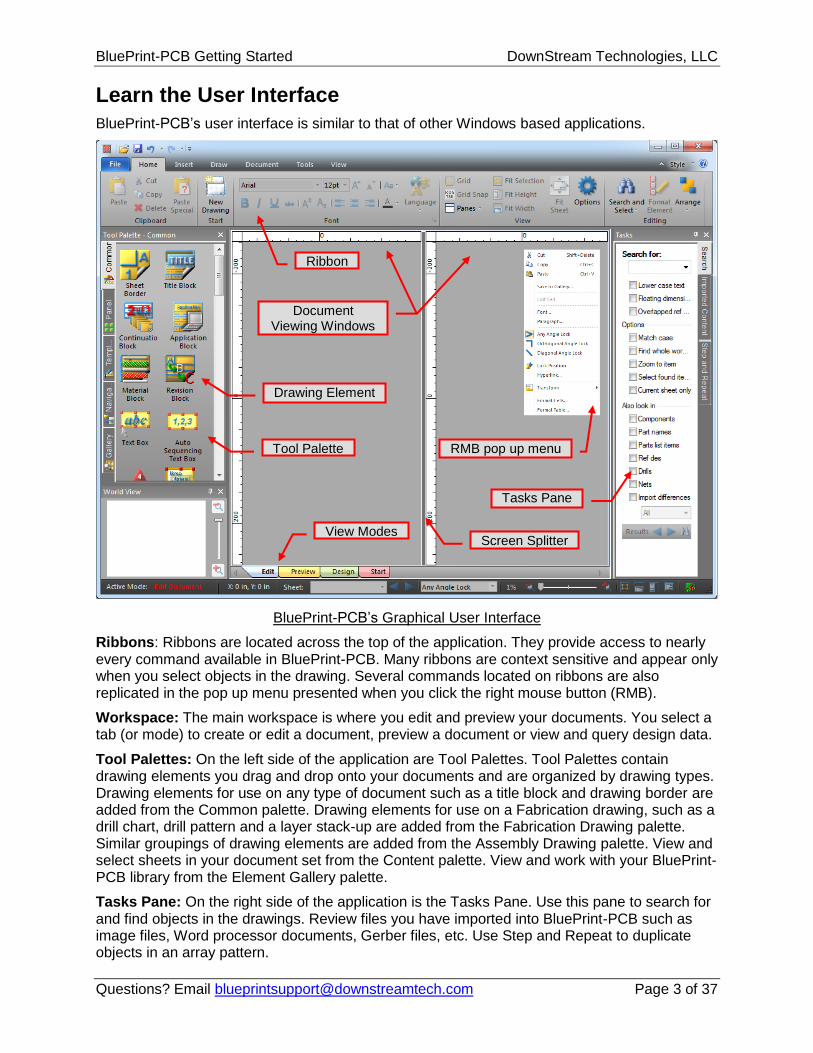
BluePrint-PCB’s user interface is similar to that of other Windows based applications.
BluePrint-PCB’s Graphical User Interface
Ribbons: Ribbons are located across the top of the application. They provide access to nearly every command available in BluePrint-PCB. Many ribbons are context sensitive and appear only when you select objects in the drawing. Several commands located on ribbons are also replicated in the pop up menu presented when you click the right mouse button (RMB).
Workspace: The main workspace is where you edit and preview your documents. You select a tab (or mode) to create or edit a document, preview a document or view and query design data.
Tool Palettes: On the left side of the application are Tool Palettes. Tool Palettes contain drawing elements you drag and drop onto your documents and are organized by drawing types. Drawing elements for use on any type of document such as a title block and drawing border are added from the Common palette. Drawing elements for use on a Fabrication drawing, such as a drill chart, drill pattern and a layer stack-up are added from the Fabrication Drawing palette. Similar groupings of drawing elements are added from the Assembly Drawing palette. View and select sheets in your document set from the Content palette. View and work with your BluePrint-PCB library from the Element Gallery palette.
Tasks Pane: On the right side of the application is the Tasks Pane. Use this pane to search for and find objects in the drawings. Review files you have imported into BluePrint-PCB such as image files, Word processor documents, Gerber files, etc. Use Step and Repeat to duplicate objects in an array pattern.
1. If not already started, start BluePrint-PCB. BluePrint-PCB’s Start screen is presented with links to help you start a release package, access this tutorial, access the help system and other activities. The Select Start-up File dialog appears.
2. Select the Inches Units.bps file and click OK to apply the Start-Up file.
Import CAD Design Data
1. Most release packages are initiated by importing design data from a CAD system. For this tutorial, you will import a sample design in ODB++ format. Select Ribbon: Home > New From Import > Mentor > Expedition ODB++ .
2. Browse to and select the BluePrint-PCB Demo Rev 1.tgz file from <Your BluePrint-PCB Installation Folder>/Demo Files folder.
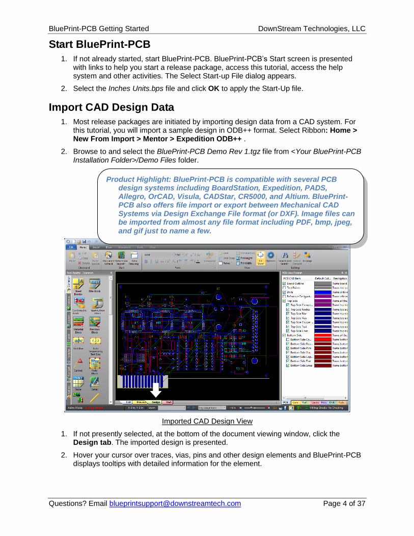
Imported CAD Design View
1. If not presently selected, at the bottom of the document viewing window, click the Design tab. The imported design is presented.
2. Hover your cursor over traces, vias, pins and other design elements and BluePrint-PCB displays tooltips with detailed information for the element.
Product Highlight: BluePrint-PCB is compatible with several PCB design systems including BoardStation, Expedition, PADS, Allegro, OrCAD, Visula, CADStar, CR5000, and Altium. BluePrint-PCB also offers file import or export between Mechanical CAD Systems via Design Exchange File format (or DXF). Image files can be imported from almost any file format including PDF, bmp, jpeg, and gif just to name a few.
1. Select Ribbon: Home > New Drawing and choose Fabrication Drawing. The View mode changes to Edit mode and a new blank sheet appears.
2. If the new drawing has a sheet border and title block, skip to “Add a Drill Pattern”.
3. If it is not open, click the Common Tool Palette
4. In the Common Tool Palette, locate your cursor over the Sheet Border element. Press and hold left mouse button, move your mouse over the blank sheet and release the mouse button to drop a sheet border element onto the sheet. Note how the sheet border is automatically positioned in the proper location.
5. Repeat the drag and drop process to add Title Block and Revision Block elements to the sheet. Note how the elements are also properly positioned on the sheet.
Add a Drill Pattern
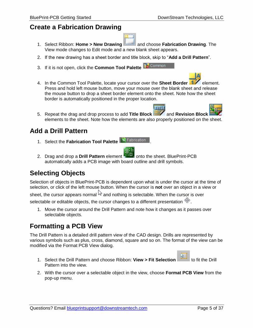
1. Select the Fabrication Tool Palette .
2. Drag and drop a Drill Pattern element onto the sheet. BluePrint-PCB automatically adds a PCB image with board outline and drill symbols.
Selecting Objects
Selection of objects in BluePrint-PCB is dependent upon what is under the cursor at the time of selection, or click of the left mouse button. When the cursor is not over an object in a view or
sheet, the cursor appears normal and nothing is selectable. When the cursor is over
selectable or editable objects, the cursor changes to a different presentation .
1. Move the cursor around the Drill Pattern and note how it changes as it passes over selectable objects.
Formatting a PCB View
The Drill Pattern is a detailed drill pattern view of the CAD design. Drills are represented by various symbols such as plus, cross, diamond, square and so on. The format of the view can be modified via the Format PCB View dialog.
1. Select the Drill Pattern and choose Ribbon: View > Fit Selection to fit the Drill Pattern into the view.
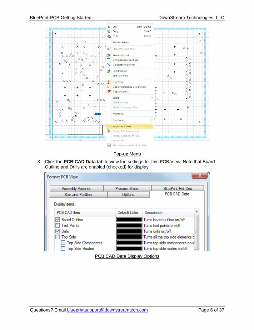
2. With the cursor over a selectable object in the view, choose Format PCB View from the pop-up menu.
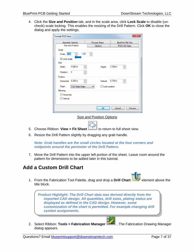
4. Click the Size and Position tab, and in the scale area, click Lock Scale to disable (un-check) scale locking. This enables the resizing of the Drill Pattern. Click OK to close the dialog and apply the settings.
Size and Position Options
5. Choose Ribbon: View > Fit Sheet to return to full sheet view.
6. Resize the Drill Pattern slightly by dragging any grab handle.
Note: Grab handles are the small circles located at the four corners and midpoints around the perimeter of the Drill Pattern.
7. Move the Drill Pattern into the upper left portion of the sheet. Leave room around the pattern for dimensions to be added later in this tutorial.
Add a Custom Drill Chart
1. From the Fabrication Tool Palette, drag and drop a Drill Chart element above the title block.
Product Highlight: The Drill Chart data was derived directly from the imported CAD design. All quantities, drill sizes, plating status are displayed as defined in the CAD design. However, some customization of the chart is permitted. For example changing drill symbol assignments.
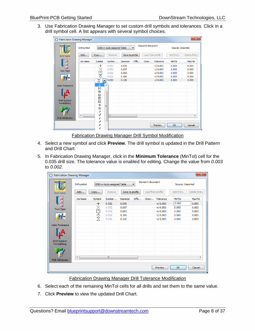
3. Use Fabrication Drawing Manager to set custom drill symbols and tolerances. Click in a drill symbol cell. A list appears with several symbol choices.
Fabrication Drawing Manager Drill Symbol Modification
4. Select a new symbol and click Preview. The drill symbol is updated in the Drill Pattern and Drill Chart.
5. In Fabrication Drawing Manager, click in the Minimum Tolerance (MinTol) cell for the 0.035 drill size. The tolerance value is enabled for editing. Change the value from 0.003 to 0.002.
8. Once you have set symbol assignment and tolerances, you can save these settings as a BluePrint-PCB user profile for use on other fabrication documents you create. To do this, select Save To Profile on the Fabrication Drawing Manager. The Drill Table is saved to your user profile.
9. Click OK to close the Fabrication Drawing Manager and keep the settings.
Add a Layer Stack-up Detail
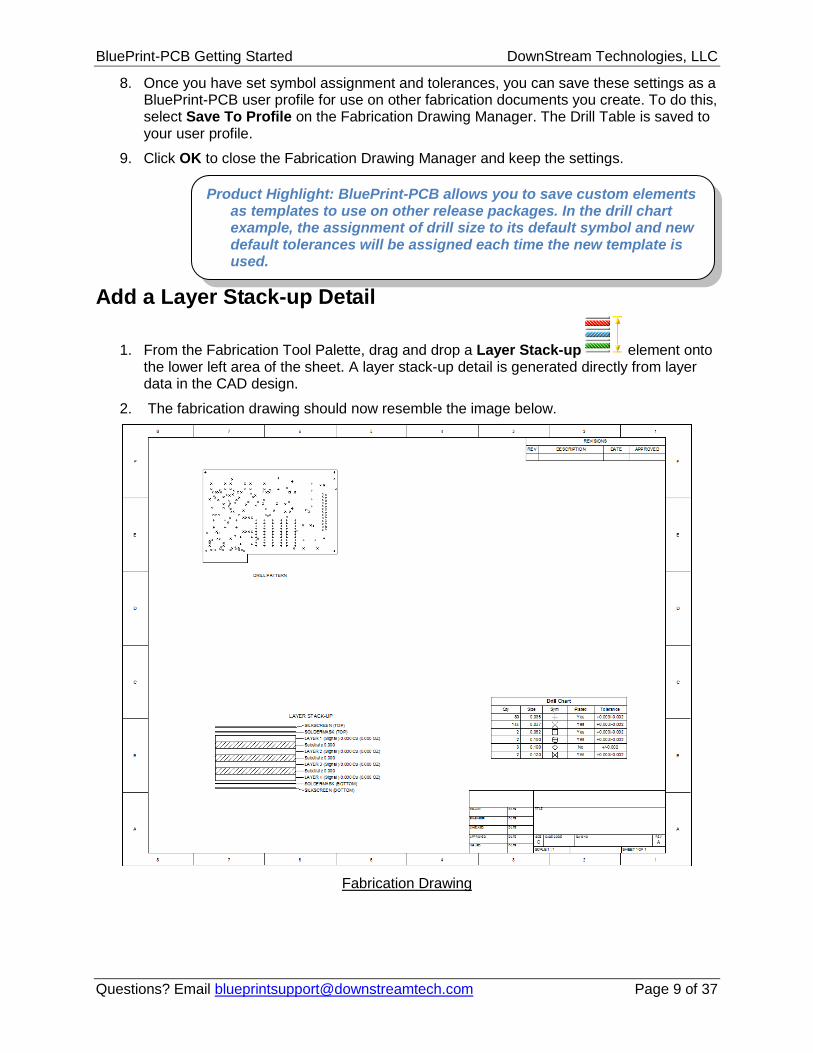
1. From the Fabrication Tool Palette, drag and drop a Layer Stack-up element onto the lower left area of the sheet. A layer stack-up detail is generated directly from layer data in the CAD design.
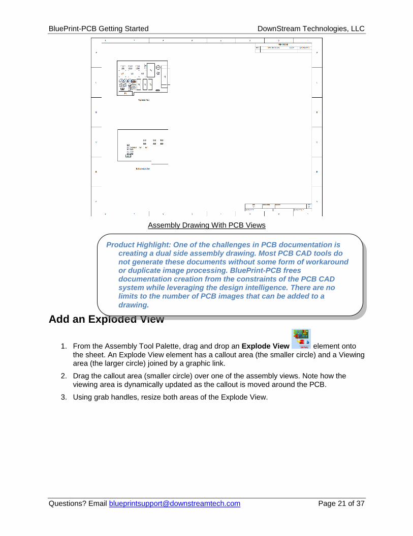
2. The fabrication drawing should now resemble the image below.
Fabrication Drawing
Product Highlight: BluePrint-PCB allows you to save custom elements as templates to use on other release packages. In the drill chart example, the assignment of drill size to its default symbol and new default tolerances will be assigned each time the new template is used.
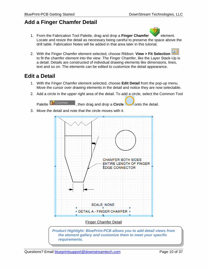
1. From the Fabrication Tool Palette, drag and drop a Finger Chamfer element. Locate and resize the detail as necessary being careful to preserve the space above the drill table. Fabrication Notes will be added in that area later in this tutorial.
2. With the Finger Chamfer element selected, choose Ribbon: View > Fit Selection to fit the chamfer element into the view. The Finger Chamfer, like the Layer Stack-Up is a detail. Details are constructed of individual drawing elements like dimensions, lines, text and so on. The elements can be edited to customize the detail appearance.
Edit a Detail
1. With the Finger Chamfer element selected, choose Edit Detail from the pop-up menu. Move the cursor over drawing elements in the detail and notice they are now selectable.
2. Add a circle in the upper right area of the detail. To add a circle, select the Common Tool
Palette , then drag and drop a Circle onto the detail.
3. Move the detail and note that the circle moves with it.
Finger Chamfer Detail
Product Highlight: BluePrint-PCB allows you to add detail views from the element gallery and customize them to meet your specific
1. Choose Ribbon: View > Fit Sheet to return to full sheet view.
2. Locate the cursor at the center of the Drill Pattern and using the Ctrl+Mouse Wheel to zoom in on the drill pattern. Two or three mouse wheel clicks should be enough.
3. Choose Ribbon: Draw > Auto Dimension and add dimensions using the following steps.
4. Locate the cursor over the lower left Horizontal segment of the board outline on the Drill Pattern and it will become highlighted.
Board Outline Segment Highlighted
5. With a segment highlighted, press and hold the left mouse button and drag a new dimension for the segment.
6. Release the mouse button to place the dimension.
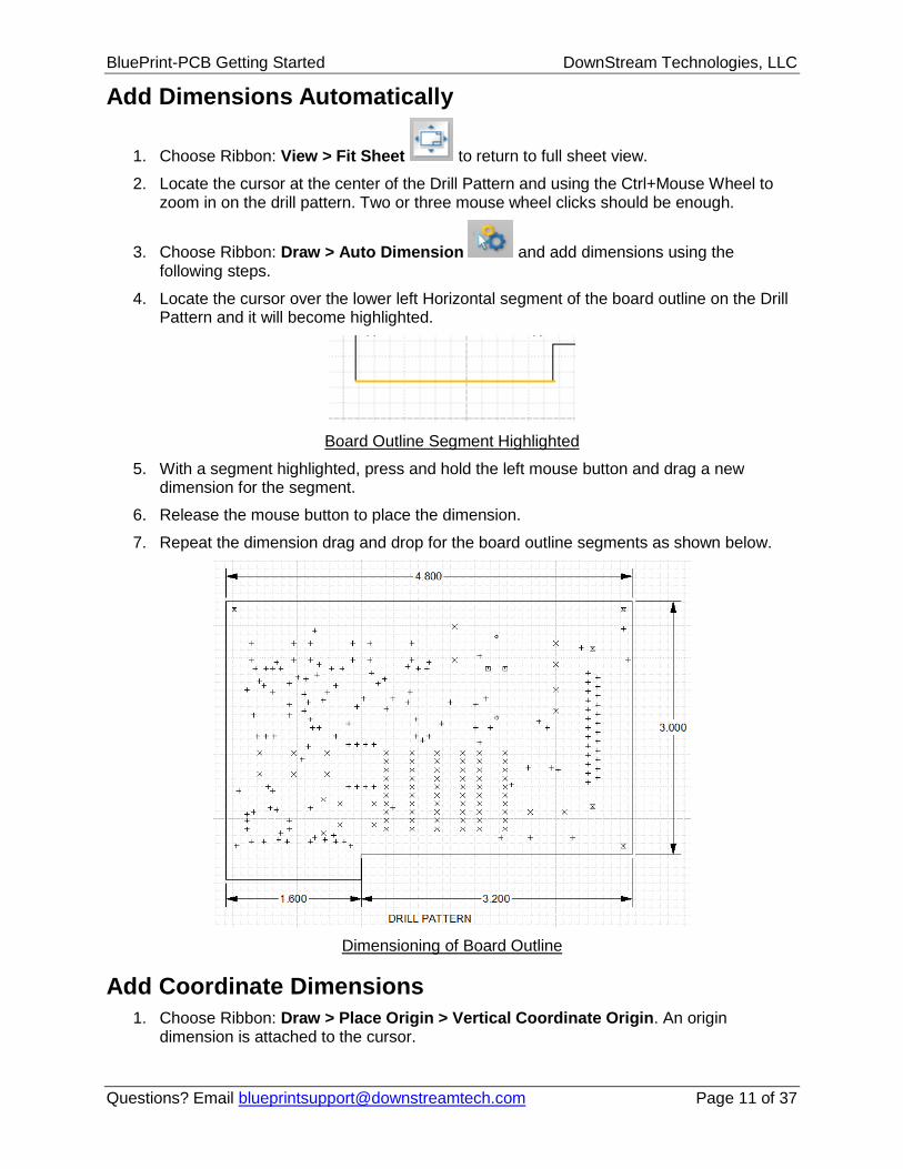
7. Repeat the dimension drag and drop for the board outline segments as shown below.
Dimensioning of Board Outline
Add Coordinate Dimensions
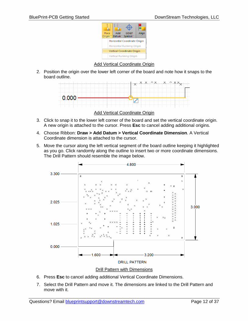
1. Choose Ribbon: Draw > Place Origin > Vertical Coordinate Origin. An origin dimension is attached to the cursor.
2. Position the origin over the lower left corner of the board and note how it snaps to the board outline.
Add Vertical Coordinate Origin
3. Click to snap it to the lower left corner of the board and set the vertical coordinate origin. A new origin is attached to the cursor. Press Esc to cancel adding additional origins.
4. Choose Ribbon: Draw > Add Datum > Vertical Coordinate Dimension. A Vertical Coordinate dimension is attached to the cursor.
5. Move the cursor along the left vertical segment of the board outline keeping it highlighted as you go. Click randomly along the outline to insert two or more coordinate dimensions. The Drill Pattern should resemble the image below.
Drill Pattern with Dimensions
6. Press Esc to cancel adding additional Vertical Coordinate Dimensions.
7. Select the Drill Pattern and move it. The dimensions are linked to the Drill Pattern and move with it.
8. Resize the Drill Pattern using its grab handles. The dimension values remain unchanged when the image is resized. The size of the PCB is not adjusted, only the scale of the view.
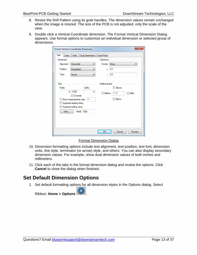
9. Double click a Vertical Coordinate dimension. The Format Vertical Dimension Dialog appears. Use format options to customize an individual dimension or selected group of dimensions.
Format Dimension Dialog
10. Dimension formatting options include text alignment, text position, text font, dimension units, line style, terminator (or arrow) style, and others. You can also display secondary dimension values. For example, show dual dimension values of both inches and millimeters.
11. Click each of the tabs in the format dimension dialog and review the options. Click Cancel to close the dialog when finished.
Set Default Dimension Options
1. Set default formatting options for all dimension styles in the Options dialog. Select
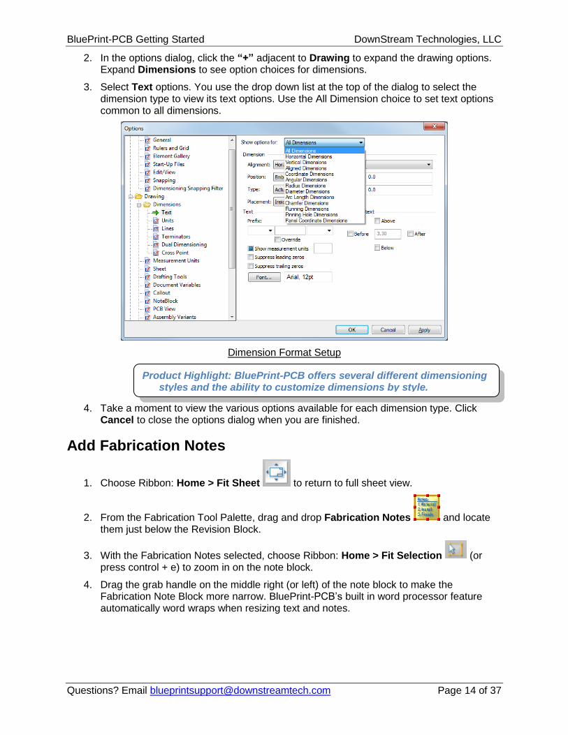
2. In the options dialog, click the “+” adjacent to Drawing to expand the drawing options. Expand Dimensions to see option choices for dimensions.
3. Select Text options. You use the drop down list at the top of the dialog to select the dimension type to view its text options. Use the All Dimension choice to set text options common to all dimensions.
Dimension Format Setup
4. Take a moment to view the various options available for each dimension type. Click Cancel to close the options dialog when you are finished.
Add Fabrication Notes
1. Choose Ribbon: Home > Fit Sheet to return to full sheet view.
2. From the Fabrication Tool Palette, drag and drop Fabrication Notes and locate them just below the Revision Block.
3. With the Fabrication Notes selected, choose Ribbon: Home > Fit Selection (or press control + e) to zoom in on the note block.
4. Drag the grab handle on the middle right (or left) of the note block to make the Fabrication Note Block more narrow. BluePrint-PCB’s built in word processor feature automatically word wraps when resizing text and notes.
Product Highlight: BluePrint-PCB offers several different dimensioning styles and the ability to customize dimensions by style.
1. Select the Note 6 text. All of the Note 6 text is highlighted. Within the text, the word imageable appears underlined in red. The underline is a result of BluePrint-PCB’s spell checking.
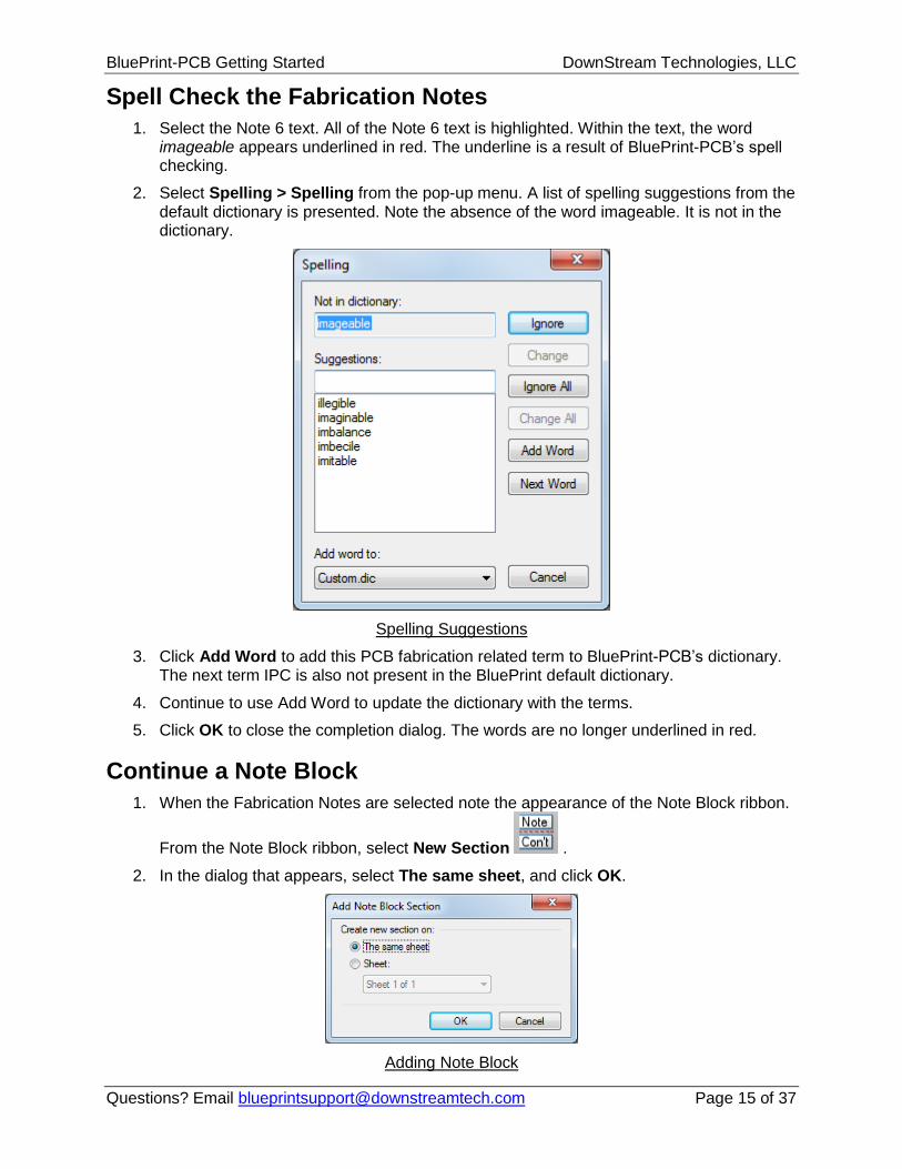
2. Select Spelling > Spelling from the pop-up menu. A list of spelling suggestions from the default dictionary is presented. Note the absence of the word imageable. It is not in the dictionary.
Spelling Suggestions
3. Click Add Word to add this PCB fabrication related term to BluePrint-PCB’s dictionary. The next term IPC is also not present in the BluePrint default dictionary.
4. Continue to use Add Word to update the dictionary with the terms.
5. Click OK to close the completion dialog. The words are no longer underlined in red.
Continue a Note Block
1. When the Fabrication Notes are selected note the appearance of the Note Block ribbon.
From the Note Block ribbon, select New Section .
2. In the dialog that appears, select The same sheet, and click OK.
3. A continuation note block section is attached to the cursor, locate it in an empty space on the sheet and click to place it. Note the addition of CONTINUED to the end of the original Fabrication Notes.
4. With the new continuation section selected, choose Ribbon: Note Block > Add New from the Notes group. A new blank Note 8 is created.
5. Enter PCB assembly to be RoHS compliant per IPC standards.
6. Click the CLICK TO ENTER HEADER string and enter Continued from Sheet 1.
7. Click in an empty area of the continuation block to unselect the header and select the block.
8. With the continuation block selected, choose Ribbon: Format > Footer to turn off the display of the note footer.
9. The note numbering was continued from the original note block into the new note block section. Both sections comprise one note block split into multiple sections. Note blocks can be split across the same sheet, or different sheets.
10. Click in an open area of the sheet to unselect the Note Block when finished.
Add a Note Linked Callout
1. Choose Ribbon: View > Fit Sheet to return to full sheet view.
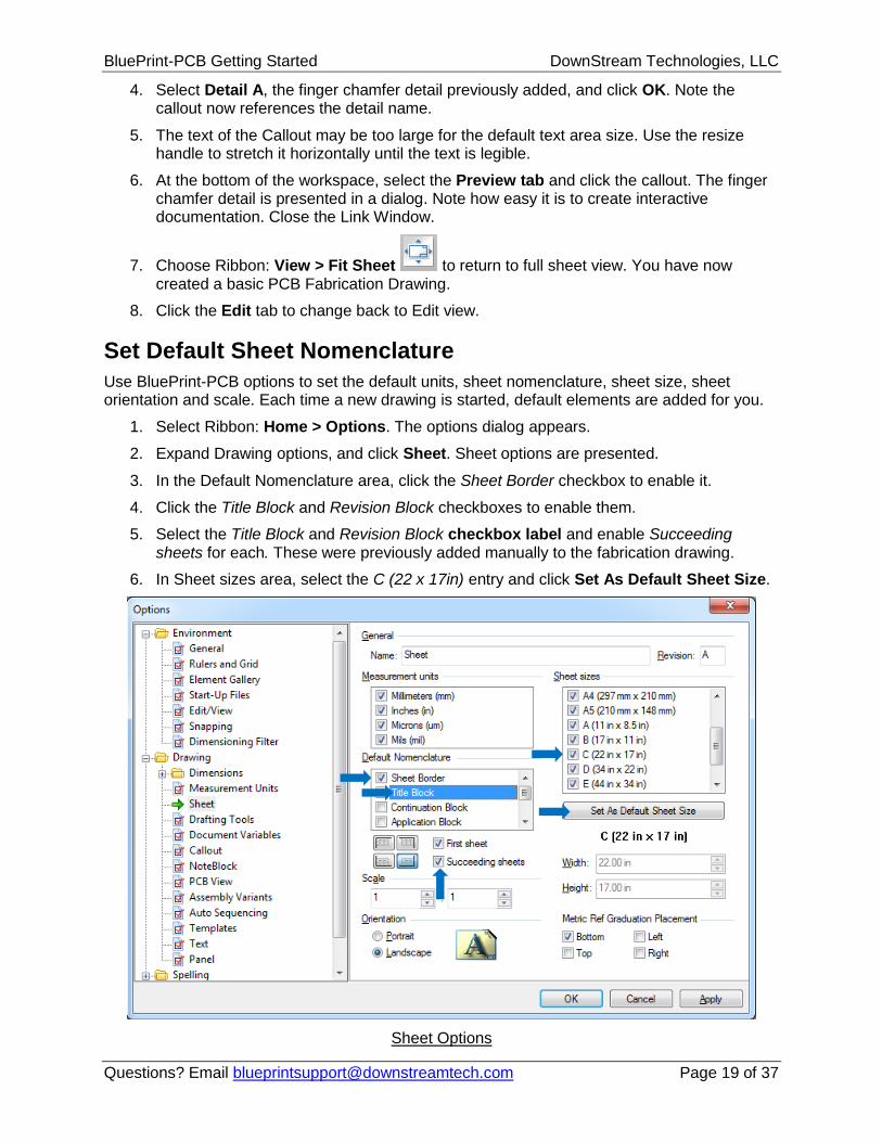
2. Select Note 3 and choose Ribbon: Note Block > Number Callout to add a callout symbol linked to Note 3. A callout is attached to the cursor.
3. Zoom into the lower right area of the Drill Pattern.
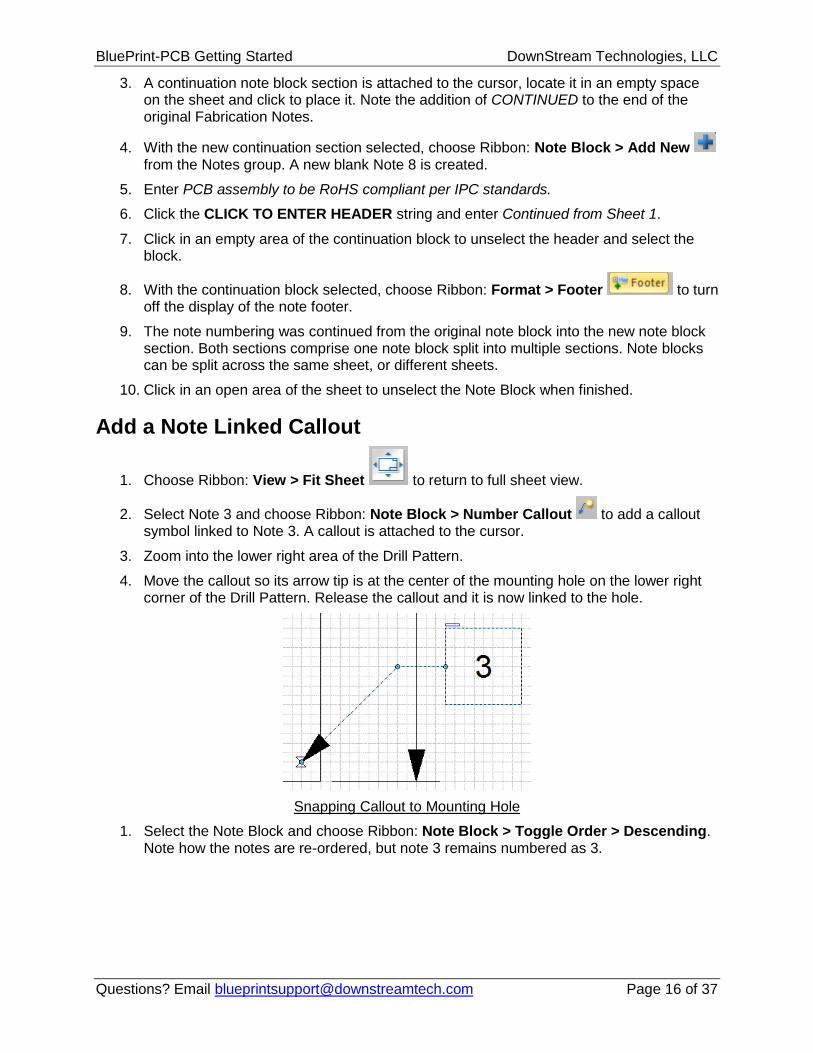
4. Move the callout so its arrow tip is at the center of the mounting hole on the lower right corner of the Drill Pattern. Release the callout and it is now linked to the hole.
Snapping Callout to Mounting Hole
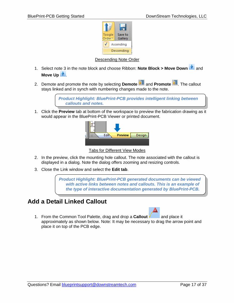
1. Select the Note Block and choose Ribbon: Note Block > Toggle Order > Descending. Note how the notes are re-ordered, but note 3 remains numbered as 3.
1. Select note 3 in the note block and choose Ribbon: Note Block > Move Down and
Move Up .
2. Demote and promote the note by selecting Demote and Promote . The callout stays linked and in synch with numbering changes made to the note.
1. Click the Preview tab at bottom of the workspace to preview the fabrication drawing as it would appear in the BluePrint-PCB Viewer or printed document.
Tabs for Different View Modes
2. In the preview, click the mounting hole callout. The note associated with the callout is displayed in a dialog. Note the dialog offers zooming and resizing controls.
3. Close the Link window and select the Edit tab.
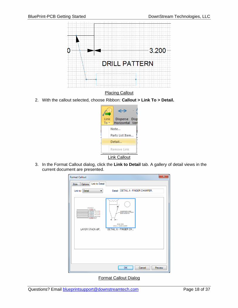
Add a Detail Linked Callout
1. From the Common Tool Palette, drag and drop a Callout and place it approximately as shown below. Note: It may be necessary to drag the arrow point and place it on top of the PCB edge.
Product Highlight: BluePrint-PCB provides intelligent linking between callouts and notes.
Product Highlight: BluePrint-PCB generated documents can be viewed with active links between notes and callouts. This is an example of
the type of interactive documentation generated by BluePrint-PCB.
4. Select Detail A, the finger chamfer detail previously added, and click OK. Note the callout now references the detail name.
5. The text of the Callout may be too large for the default text area size. Use the resize handle to stretch it horizontally until the text is legible.
6. At the bottom of the workspace, select the Preview tab and click the callout. The finger chamfer detail is presented in a dialog. Note how easy it is to create interactive documentation. Close the Link Window.
7. Choose Ribbon: View > Fit Sheet to return to full sheet view. You have now created a basic PCB Fabrication Drawing.
8. Click the Edit tab to change back to Edit view.
Set Default Sheet Nomenclature
Use BluePrint-PCB options to set the default units, sheet nomenclature, sheet size, sheet orientation and scale. Each time a new drawing is started, default elements are added for you.
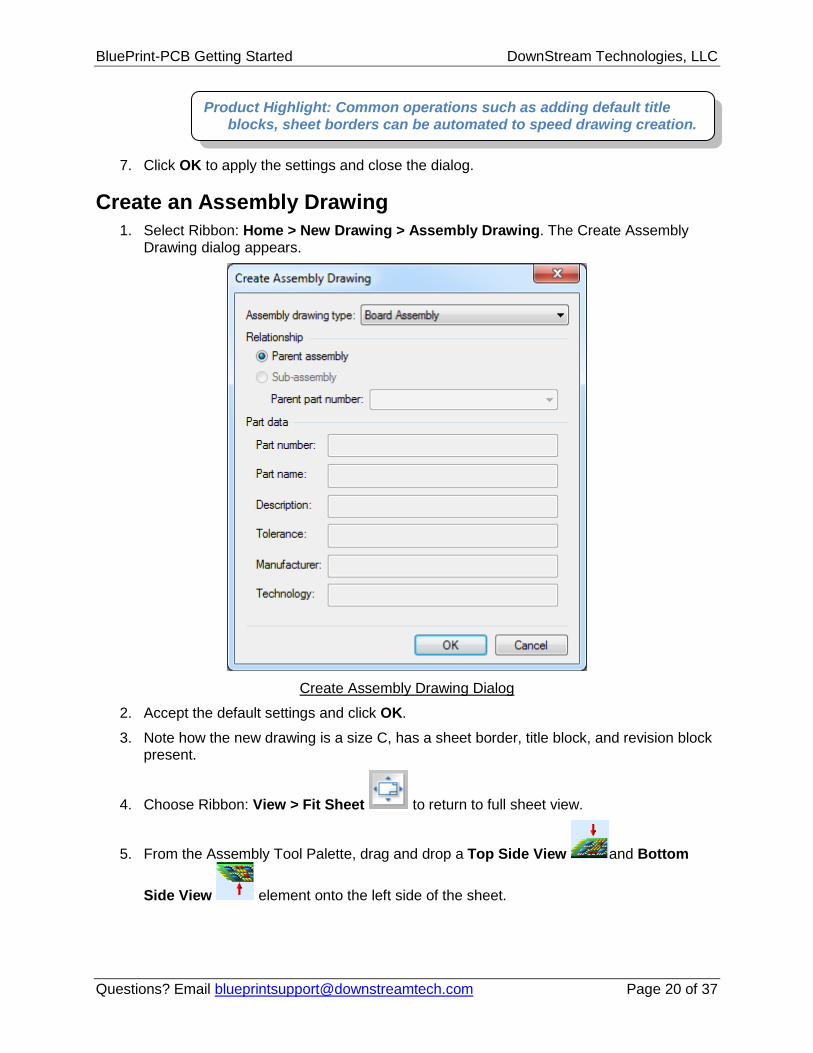
1. Select Ribbon: Home > Options. The options dialog appears.
2. Expand Drawing options, and click Sheet. Sheet options are presented.
3. In the Default Nomenclature area, click the Sheet Border checkbox to enable it.
4. Click the Title Block and Revision Block checkboxes to enable them.
5. Select the Title Block and Revision Block checkbox label and enable Succeeding sheets for each. These were previously added manually to the fabrication drawing.
6. In Sheet sizes area, select the C (22 x 17in) entry and click Set As Default Sheet Size.
1. From the Assembly Tool Palette, drag and drop an Explode View element onto the sheet. An Explode View element has a callout area (the smaller circle) and a Viewing area (the larger circle) joined by a graphic link.
2. Drag the callout area (smaller circle) over one of the assembly views. Note how the viewing area is dynamically updated as the callout is moved around the PCB.
3. Using grab handles, resize both areas of the Explode View.
Product Highlight: One of the challenges in PCB documentation is creating a dual side assembly drawing. Most PCB CAD tools do not generate these documents without some form of workaround or duplicate image processing. BluePrint-PCB frees documentation creation from the constraints of the PCB CAD system while leveraging the design intelligence. There are no limits to the number of PCB images that can be added to a
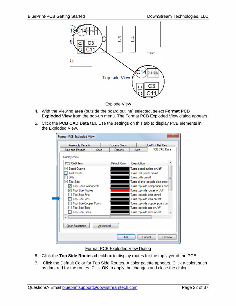
4. With the Viewing area (outside the board outline) selected, select Format PCB Exploded View from the pop-up menu. The Format PCB Exploded View dialog appears.
5. Click the PCB CAD Data tab. Use the settings on this tab to display PCB elements in the Exploded View.
Format PCB Exploded View Dialog
6. Click the Top Side Routes checkbox to display routes for the top layer of the PCB.
7. Click the Default Color for Top Side Routes. A color palette appears. Click a color, such as dark red for the routes. Click OK to apply the changes and close the dialog.
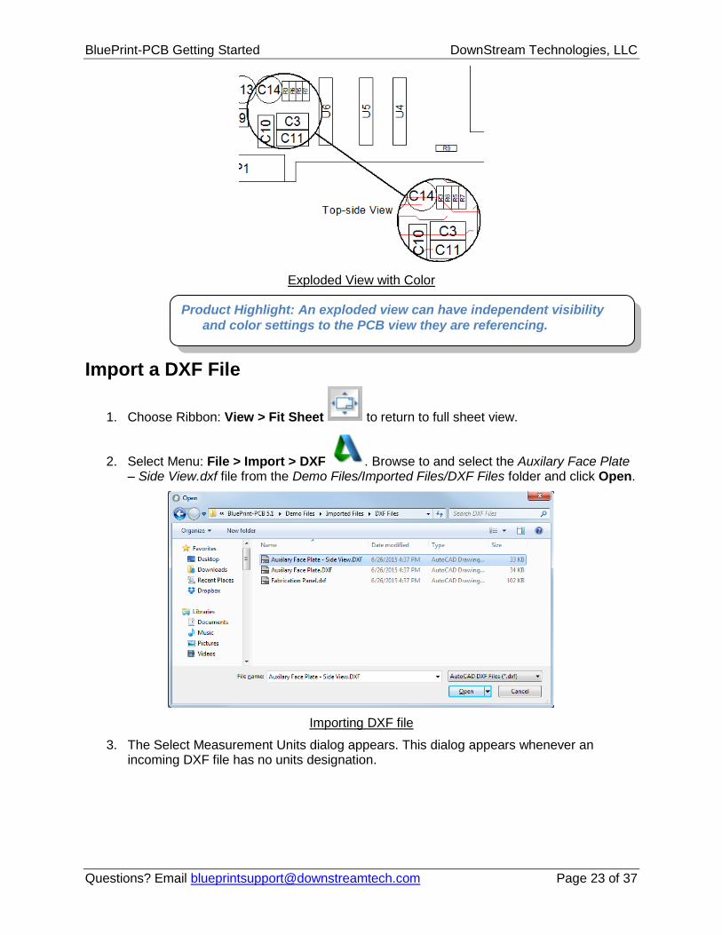
1. Choose Ribbon: View > Fit Sheet to return to full sheet view.
2. Select Menu: File > Import > DXF . Browse to and select the Auxilary Face Plate – Side View.dxf file from the Demo Files/Imported Files/DXF Files folder and click Open.
Importing DXF file
3. The Select Measurement Units dialog appears. This dialog appears whenever an incoming DXF file has no units designation.
Product Highlight: An exploded view can have independent visibility
and color settings to the PCB view they are referencing.
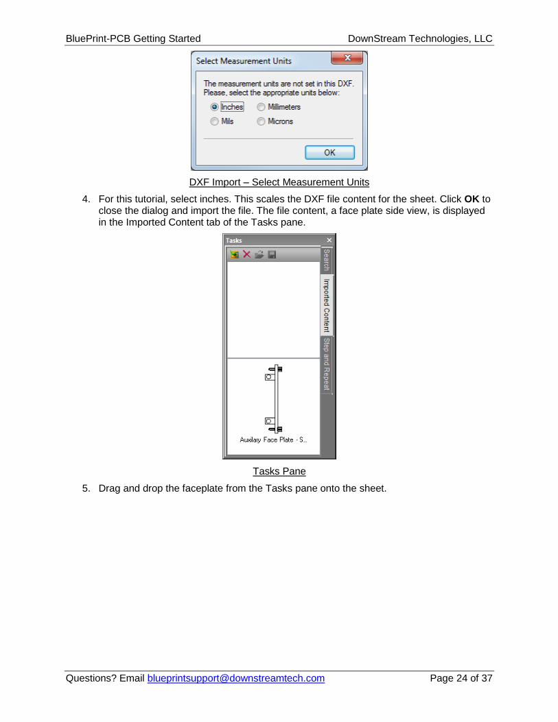
4. For this tutorial, select inches. This scales the DXF file content for the sheet. Click OK to close the dialog and import the file. The file content, a face plate side view, is displayed in the Imported Content tab of the Tasks pane.
Tasks Pane
5. Drag and drop the faceplate from the Tasks pane onto the sheet.
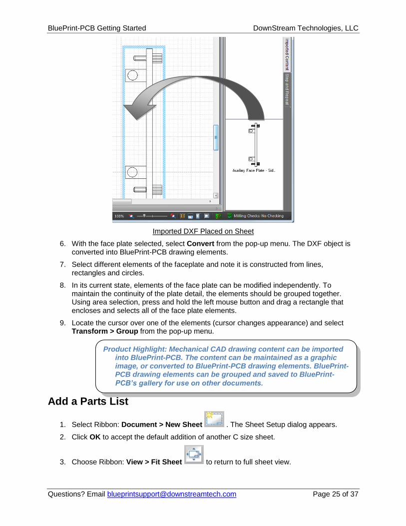
6. With the face plate selected, select Convert from the pop-up menu. The DXF object is converted into BluePrint-PCB drawing elements.
7. Select different elements of the faceplate and note it is constructed from lines, rectangles and circles.
8. In its current state, elements of the face plate can be modified independently. To maintain the continuity of the plate detail, the elements should be grouped together. Using area selection, press and hold the left mouse button and drag a rectangle that encloses and selects all of the face plate elements.
9. Locate the cursor over one of the elements (cursor changes appearance) and select Transform > Group from the pop-up menu.
Add a Parts List
1. Select Ribbon: Document > New Sheet . The Sheet Setup dialog appears.
2. Click OK to accept the default addition of another C size sheet.
3. Choose Ribbon: View > Fit Sheet to return to full sheet view.
Product Highlight: Mechanical CAD drawing content can be imported into BluePrint-PCB. The content can be maintained as a graphic image, or converted to BluePrint-PCB drawing elements. BluePrint-PCB drawing elements can be grouped and saved to BluePrint-
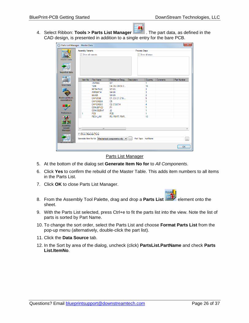
4. Select Ribbon: Tools > Parts List Manager . The part data, as defined in the CAD design, is presented in addition to a single entry for the bare PCB.
Parts List Manager
5. At the bottom of the dialog set Generate Item No for to All Components.
6. Click Yes to confirm the rebuild of the Master Table. This adds item numbers to all items in the Parts List.
7. Click OK to close Parts List Manager.
8. From the Assembly Tool Palette, drag and drop a Parts List element onto the sheet.
9. With the Parts List selected, press Ctrl+e to fit the parts list into the view. Note the list of parts is sorted by Part Name.
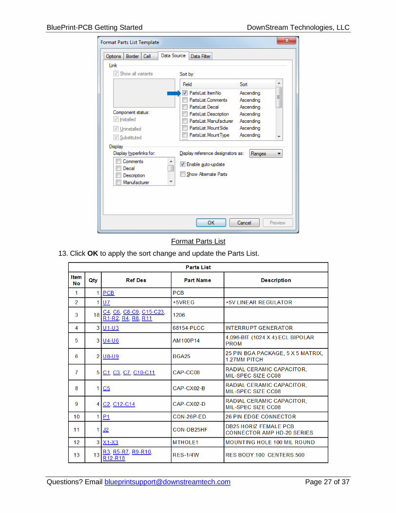
10. To change the sort order, select the Parts List and choose Format Parts List from the pop-up menu (alternatively, double-click the part list).
11. Click the Data Source tab.
12. In the Sort by area of the dialog, uncheck (click) PartsList.PartName and check Parts List.ItemNo.
1. Select Ribbon: Home > New Drawing > Custom Drawing.
2. Select Fit Sheet to view the entire sheet.
Import a Gerber File
1. Select File: Import > Gerber .
2. Browse to: Demo Files/Imported Files/Gerber Files folder.
3. Select the art001.pho file and click Open. The file content, a top layer gerber, is displayed in the Imported Content tab of the Tasks pane.
4. Drag and drop the image onto the sheet.
Customize a Title Block
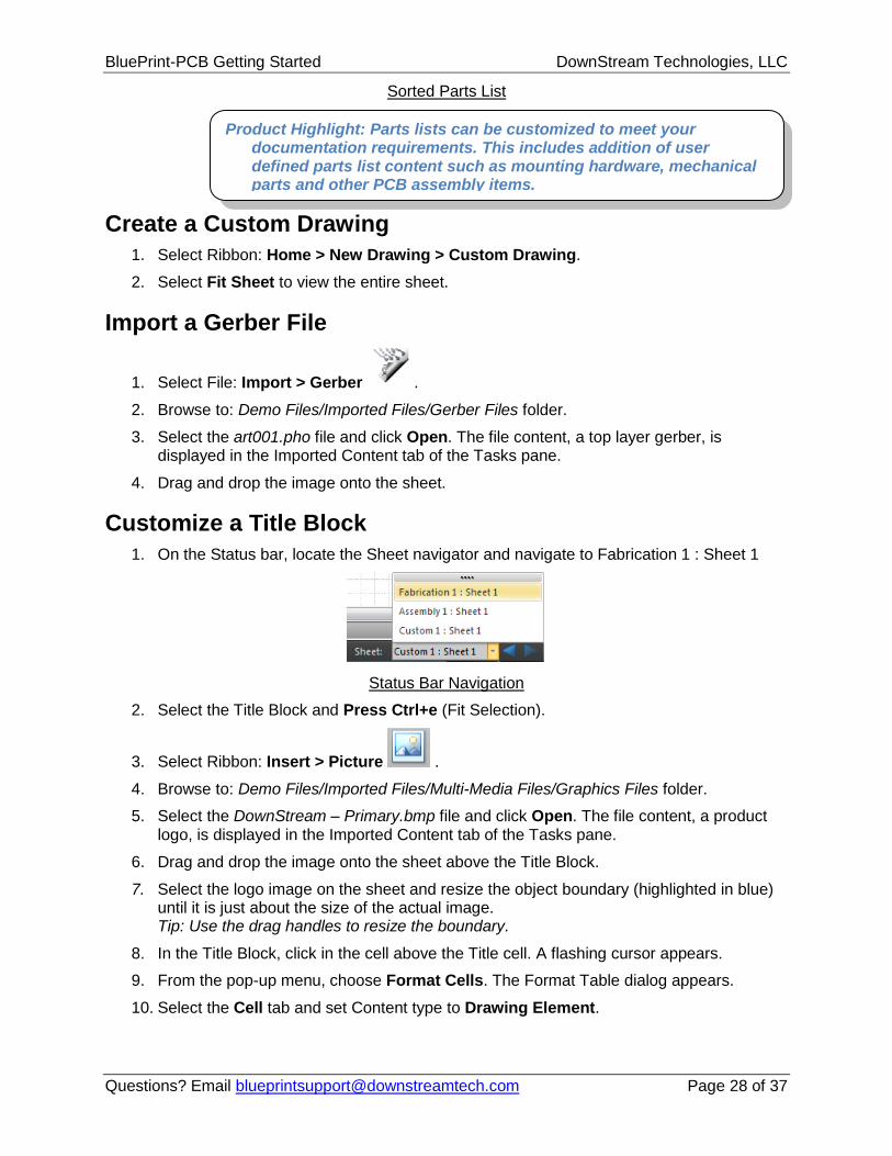
1. On the Status bar, locate the Sheet navigator and navigate to Fabrication 1 : Sheet 1
Status Bar Navigation
2. Select the Title Block and Press Ctrl+e (Fit Selection).
3. Select Ribbon: Insert > Picture .
4. Browse to: Demo Files/Imported Files/Multi-Media Files/Graphics Files folder.
5. Select the DownStream – Primary.bmp file and click Open. The file content, a product logo, is displayed in the Imported Content tab of the Tasks pane.
6. Drag and drop the image onto the sheet above the Title Block.
7. Select the logo image on the sheet and resize the object boundary (highlighted in blue) until it is just about the size of the actual image. Tip: Use the drag handles to resize the boundary.
8. In the Title Block, click in the cell above the Title cell. A flashing cursor appears.
9. From the pop-up menu, choose Format Cells. The Format Table dialog appears.
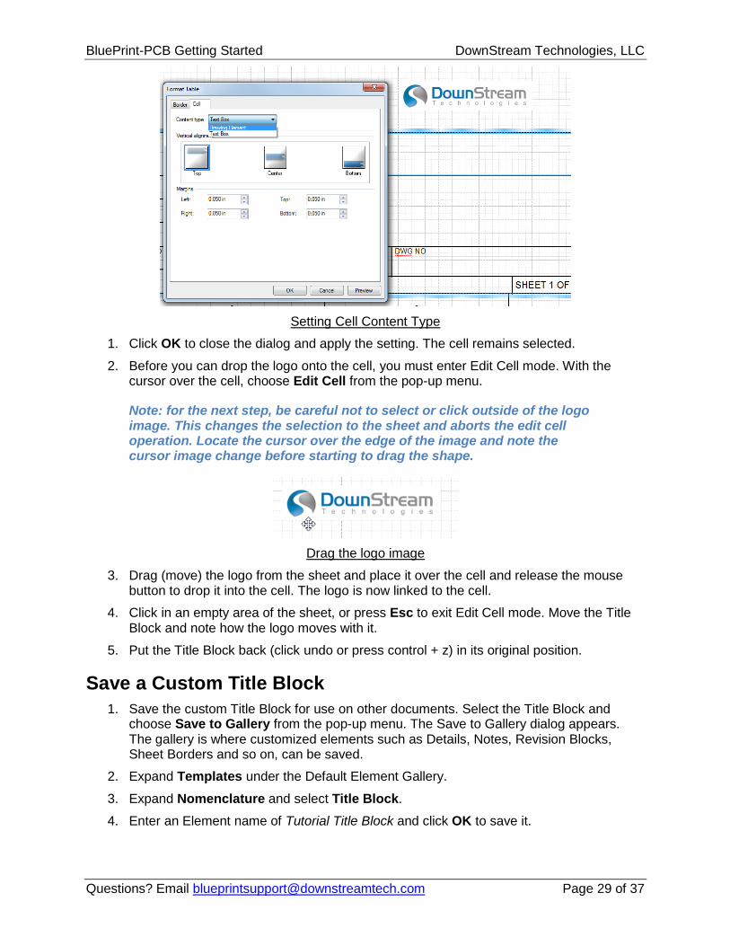
10. Select the Cell tab and set Content type to Drawing Element.
Product Highlight: Parts lists can be customized to meet your documentation requirements. This includes addition of user defined parts list content such as mounting hardware, mechanical parts and other PCB assembly items.
1. Click OK to close the dialog and apply the setting. The cell remains selected.
2. Before you can drop the logo onto the cell, you must enter Edit Cell mode. With the cursor over the cell, choose Edit Cell from the pop-up menu.
Note: for the next step, be careful not to select or click outside of the logo image. This changes the selection to the sheet and aborts the edit cell operation. Locate the cursor over the edge of the image and note the cursor image change before starting to drag the shape.
Drag the logo image
3. Drag (move) the logo from the sheet and place it over the cell and release the mouse button to drop it into the cell. The logo is now linked to the cell.
4. Click in an empty area of the sheet, or press Esc to exit Edit Cell mode. Move the Title Block and note how the logo moves with it.
5. Put the Title Block back (click undo or press control + z) in its original position.
Save a Custom Title Block
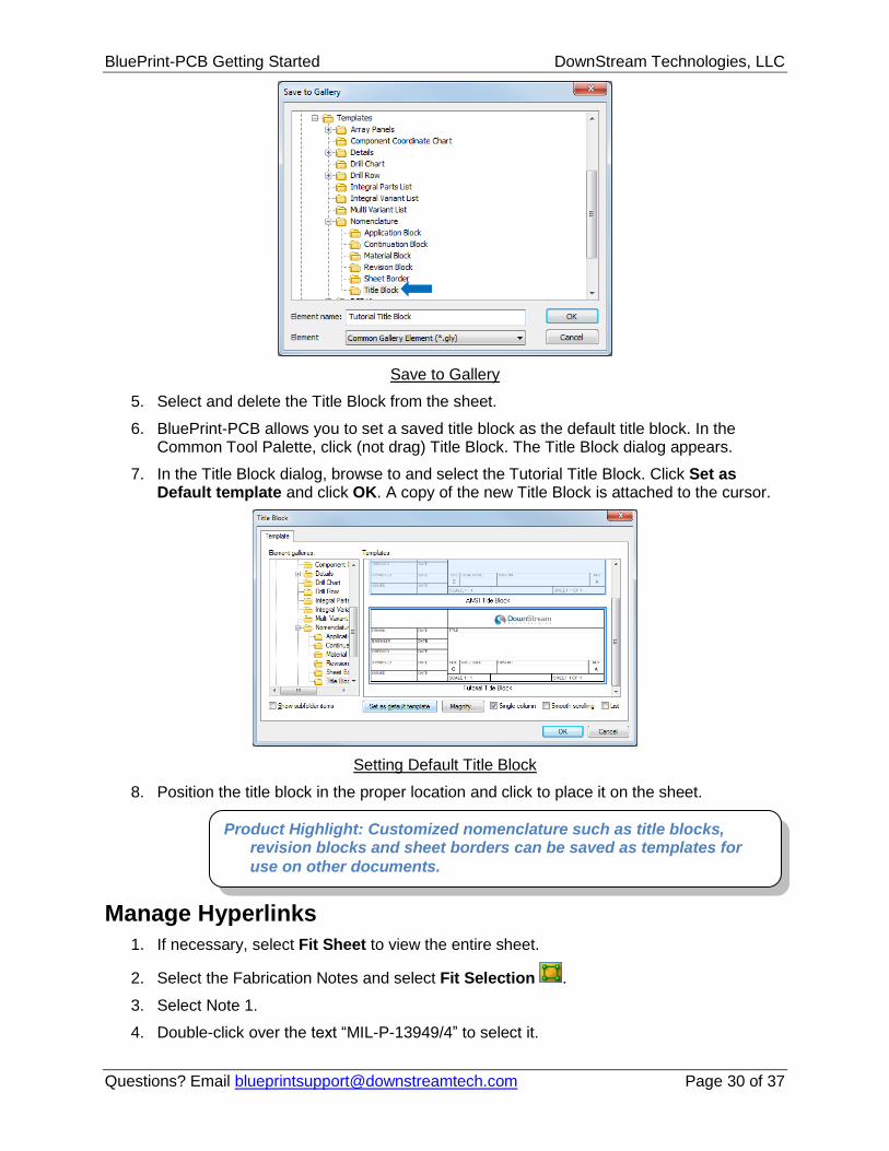
1. Save the custom Title Block for use on other documents. Select the Title Block and choose Save to Gallery from the pop-up menu. The Save to Gallery dialog appears. The gallery is where customized elements such as Details, Notes, Revision Blocks, Sheet Borders and so on, can be saved.
2. Expand Templates under the Default Element Gallery.
3. Expand Nomenclature and select Title Block.
4. Enter an Element name of Tutorial Title Block and click OK to save it.
5. Select and delete the Title Block from the sheet.
6. BluePrint-PCB allows you to set a saved title block as the default title block. In the Common Tool Palette, click (not drag) Title Block. The Title Block dialog appears.
7. In the Title Block dialog, browse to and select the Tutorial Title Block. Click Set as Default template and click OK. A copy of the new Title Block is attached to the cursor.
Setting Default Title Block
8. Position the title block in the proper location and click to place it on the sheet.
Manage Hyperlinks
1. If necessary, select Fit Sheet to view the entire sheet.
2. Select the Fabrication Notes and select Fit Selection .
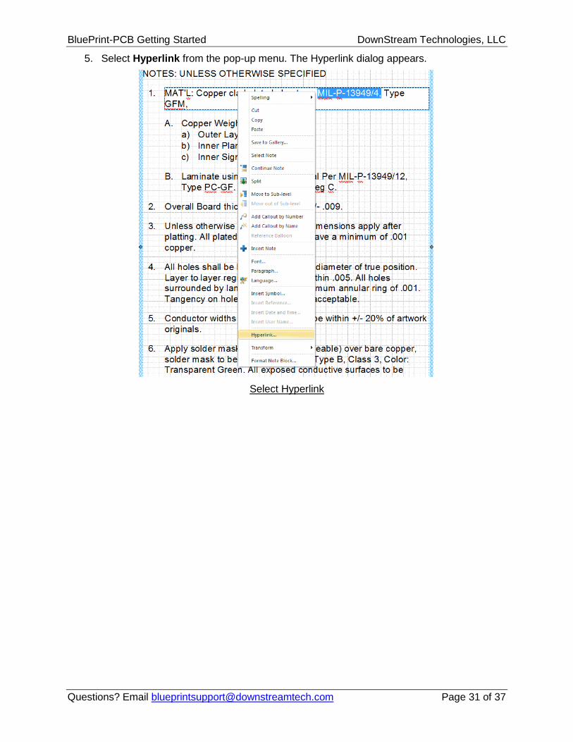
3. Select Note 1.
4. Double-click over the text “MIL-P-13949/4” to select it.
Product Highlight: Customized nomenclature such as title blocks, revision blocks and sheet borders can be saved as templates for
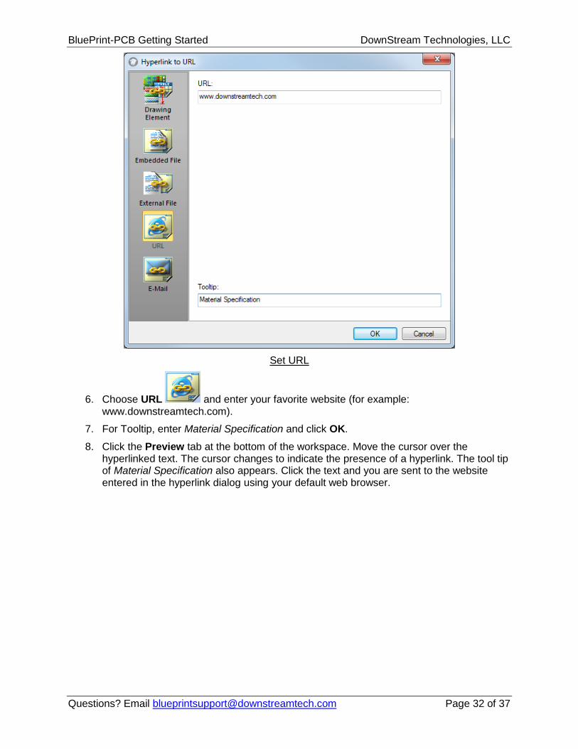
6. Choose URL and enter your favorite website (for example: www.downstreamtech.com).
7. For Tooltip, enter Material Specification and click OK.
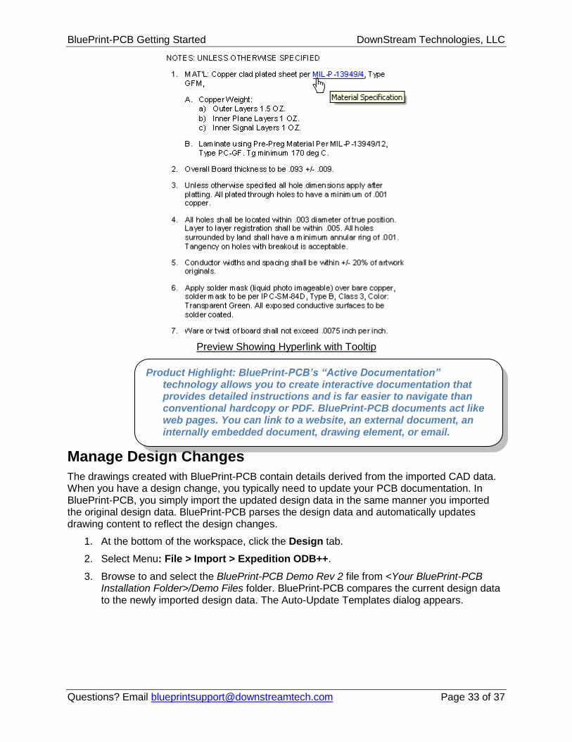
8. Click the Preview tab at the bottom of the workspace. Move the cursor over the hyperlinked text. The cursor changes to indicate the presence of a hyperlink. The tool tip of Material Specification also appears. Click the text and you are sent to the website entered in the hyperlink dialog using your default web browser.
The drawings created with BluePrint-PCB contain details derived from the imported CAD data. When you have a design change, you typically need to update your PCB documentation. In BluePrint-PCB, you simply import the updated design data in the same manner you imported the original design data. BluePrint-PCB parses the design data and automatically updates drawing content to reflect the design changes.
1. At the bottom of the workspace, click the Design tab.
2. Select Menu: File > Import > Expedition ODB++.
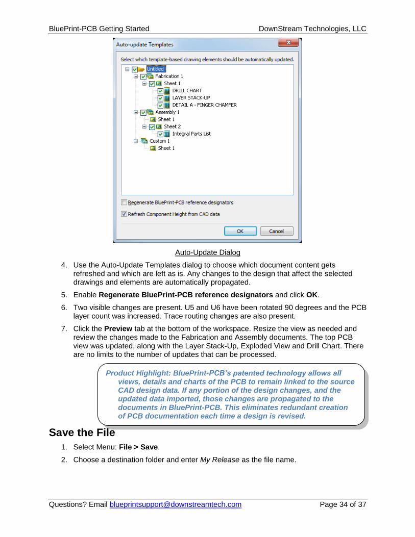
3. Browse to and select the BluePrint-PCB Demo Rev 2 file from <Your BluePrint-PCB Installation Folder>/Demo Files folder. BluePrint-PCB compares the current design data to the newly imported design data. The Auto-Update Templates dialog appears.
Product Highlight: BluePrint-PCB’s “Active Documentation” technology allows you to create interactive documentation that provides detailed instructions and is far easier to navigate than conventional hardcopy or PDF. BluePrint-PCB documents act like web pages. You can link to a website, an external document, an internally embedded document, drawing element, or email.
4. Use the Auto-Update Templates dialog to choose which document content gets refreshed and which are left as is. Any changes to the design that affect the selected drawings and elements are automatically propagated.
5. Enable Regenerate BluePrint-PCB reference designators and click OK.
6. Two visible changes are present. U5 and U6 have been rotated 90 degrees and the PCB layer count was increased. Trace routing changes are also present.
7. Click the Preview tab at the bottom of the workspace. Resize the view as needed and review the changes made to the Fabrication and Assembly documents. The top PCB view was updated, along with the Layer Stack-Up, Exploded View and Drill Chart. There are no limits to the number of updates that can be processed.
Save the File
1. Select Menu: File > Save.
2. Choose a destination folder and enter My Release as the file name.
Product Highlight: BluePrint-PCB’s patented technology allows all views, details and charts of the PCB to remain linked to the source CAD design data. If any portion of the design changes, and the updated data imported, those changes are propagated to the documents in BluePrint-PCB. This eliminates redundant creation of PCB documentation each time a design is revised.
Now that you have completed the documents required for the fabrication and assembly of the PCB, create a release package for distribution and viewing by others. Use the Pack and Release Wizard to create a release package file.
1. Select Menu: File > Tools > Pack and Release. The Pack and Release Wizard appears.
2. Review the tips on the Start panel, and click Next.
3. Browse to and select a destination folder to host the package file and click Next.
4. Accept the default inclusion of All drawings and files option and click Next.
5. Accept the default Embed True Type fonts option and click Next.
6. Include the viewer in the release package so others without BluePrint-PCB installed can view the documents. Accept the default of unlimited days of viewing and click Next.
7. Click Finish.
View the Release Package
1. Use the features of your operating system, not BluePrint-PCB, to locate and double-click the My Release.exe package file.
2. In the BluePrint-PCB Release Package dialog, accept the default location of the current folder and My Release folder name or browse to and select a different folder name and location.
3. Click UnPack to create the folder contents.
4. My Release is created and the embedded BluePrint-PCB Viewer application opens the release package files for viewing.
Publish to the Web
BluePrint-PCB’s release package can also be published for viewing via a web browser. Documents can be located on a web server along with a web enabled BluePrint-PCB viewer application.
1. Select Menu: File > Tools >Publish to Web.
2. Select the Desktop or some other location to host the published contents folder and click OK to save it.
3. Use the features of your operating system to browse and locate the My Release html file and double-click to open it.
Note: Opening an html file in this way will start your default web browser. Some web browsers are not enabled or permitted to run Active X based applications such as the BluePrint-PCB viewer. You must enable or allow the Active X applications to run to properly use the BluePrint-PCB web enabled viewer.
Product Highlight: BluePrint-PCB’s release package combined with an embedded BluePrint-PCB viewer, allow any individual involved in the fabrication, assembly, test, or QA of the PCB to view the
4. Experiment with navigating through the release documents in the viewer. Close the viewer when you are finished.
BluePrint-PCB’s Documentation Hierarchy
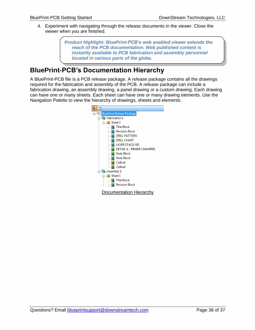
A BluePrint-PCB file is a PCB release package. A release package contains all the drawings required for the fabrication and assembly of the PCB. A release package can include a fabrication drawing, an assembly drawing, a panel drawing or a custom drawing. Each drawing can have one or many sheets. Each sheet can have one or many drawing elements. Use the Navigation Palette to view the hierarchy of drawings, sheets and elements.
Documentation Hierarchy
Product Highlight: BluePrint-PCB’s web enabled viewer extends the reach of the PCB documentation. Web published content is instantly available to PCB fabrication and assembly personnel