37
BMME 560 & BME 590I Medical Imaging: X-ray, CT, and Nuclear Methods Tomography Part 2
| Date post: | 19-Dec-2015 |
| Category: |
Documents |
| Upload: | mavis-powers |
| View: | 267 times |
| Download: | 3 times |

BMME 560 & BME 590IMedical Imaging: X-ray, CT, and
Nuclear Methods
Tomography Part 2
Today
• Tomography– Radon Transform– Fourier Slice Theorem– Direct Fourier Reconstruction– Simple Backprojection

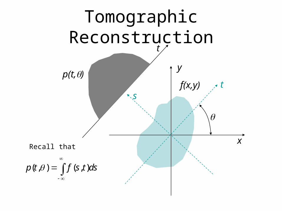
Tomographic Reconstruction
• Define terms
f(x,y)p(t,q)
t
t
y
q
x
s
The object
The projection
“Object space” or “image space”
“Projection space”
The “rotated frame”

Tomographic Reconstruction
• The problem
f(x,y)p(t,q)
t
t
y
q
x
s
Given p(t,q) for 0<q<pFind f(x,y)
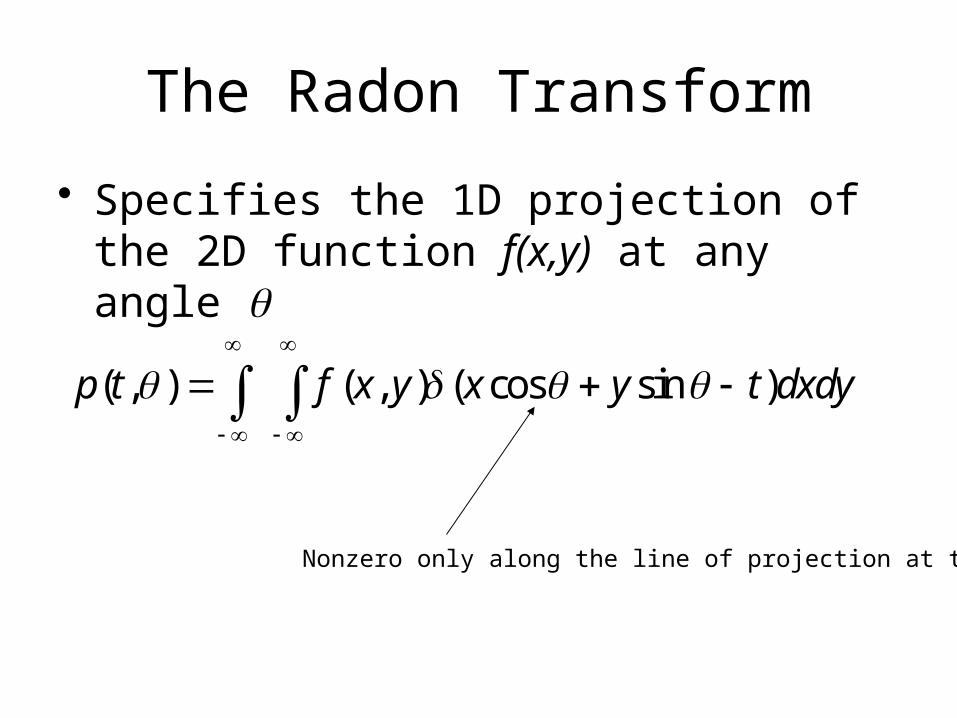
The Radon Transform
• Specifies the 1D projection of the 2D function f(x,y) at any angle q
( , ) ( , ) ( cos sin )p t f x y x y t dxdy
Nonzero only along the line of projection at t

Radon Transform Example
( , ) ( , ) ( cos sin )p t x a y x y t dxdy
( , ) ( , )f x y x a y
Both delta functions have to be nonzero for the integral to be one. This occurs when the following conditions are met:
0
0
cos sin
x a x a
y
t x y
Therefore, the transform is nonzero only when
cos So, ( , ) ( cos )t a p t t a
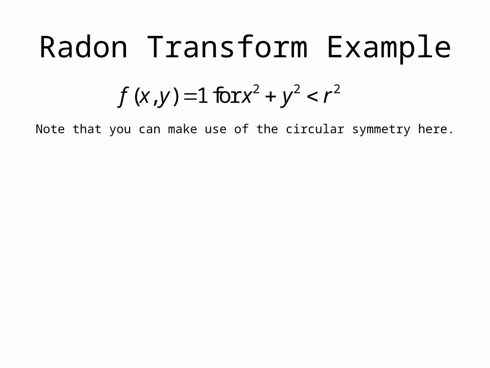
Radon Transform Example2 2 2( , ) 1 for f x y x y r
Note that you can make use of the circular symmetry here.

The delta function selects x = t since it is nonzero and integrates to one only if this is true.
Now set the limits of integration because the function is one only if t2 + y2 < r2
We could have also reached this by reasoning that the projection for any t would be the length of that chord in the circle.
Because of the circular symmetry, all projections will be the same. We can arbitrarily choose q = 0.

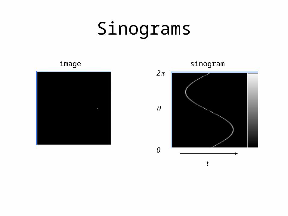
Sinograms
image sinogram
t
0
2p
q
Sinograms
image sinogram
t
0
2p
q

Sinograms
image sinogram
t
0
2p
q

Sinogram
• Here is a sinogram. What does the object look like?
Tomographic Reconstruction
f(x,y)p(t,q)
t
t
y
q
x
s
Recall that
( , ) ( , )p t f s t ds

Tomographic Reconstruction
f(x,y)
p(t,q)t
ty
qx
s
It turns out that there is a relationship between the Fourier Transforms of f(x,y) and p(t,q)
( , ) ( , )p t f s t ds

Tomographic Reconstruction
f(x,y)
p(t,q)t
ty
qx
s
Take the FT of p with respect to a frequency variable wt
( , ) ( , ) ( , ) tj ttP p t f s t ds e dt
Reorder the integrals
( , ) ( , ) tj ttP f s t e ds dt
Tomographic Reconstruction
f(x,y)
p(t,q)t
ty
qx
s
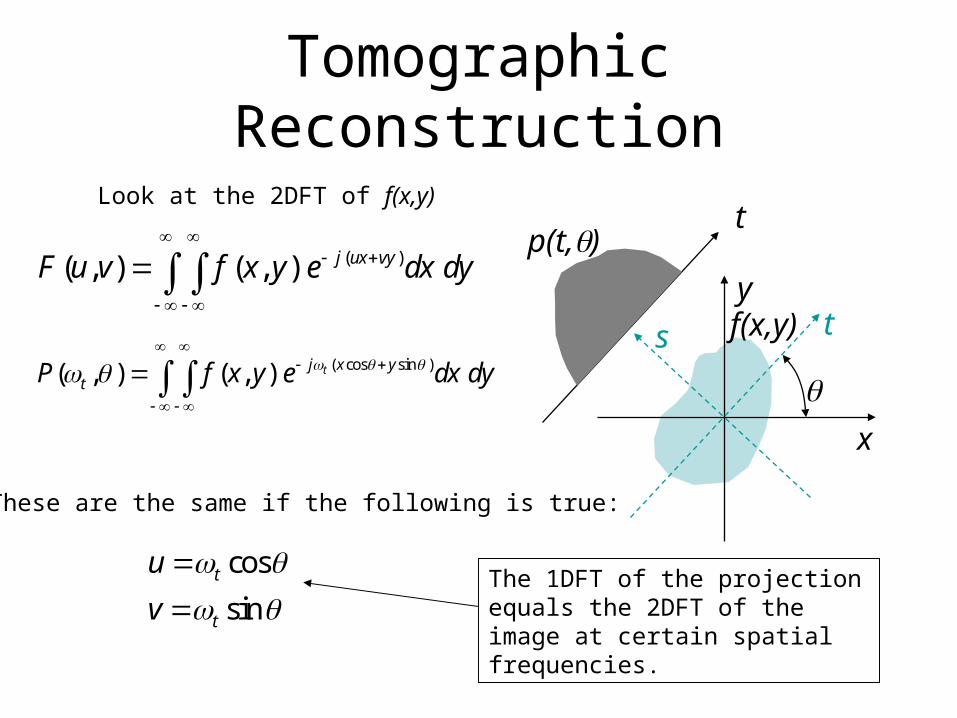
Look at the 2DFT of f(x,y)
( cos sin )( , ) ( , ) tj x ytP f x y e dx dy
( )( , ) ( , ) j ux vyF u v f x y e dx dy
These are the same if the following is true:
cos
sint
t
u
v
The 1DFT of the projection equals the 2DFT of the image at certain spatial frequencies.

Tomographic Reconstruction
f(x,y)p(y)
yy
x
These are equal if .
Consider if we project along x:The 2D FT of our object:
The projection of our object:
The 1D FT of the projection of our object:

Tomographic Reconstruction
f(x,y)
p(t,q)t
ty
qx
s
Therefore
( , ) ( cos , sin )t t tP F u v
This is called the Fourier Slice Theorem or the Projection Slice Theorem

Tomographic Reconstruction
Look at this in the Fourier Space
( , ) ( cos , sin )t t tP F u v
u
v
q
This line is described by the parametric equations on wt
wt
So, each projection angle gives us information from one line in the 2D FT space.

Tomographic Reconstruction
• Does this suggest to you a method for reconstruction from projections?
( , ) ( cos , sin )t t tP F u v
u
v
q
wt
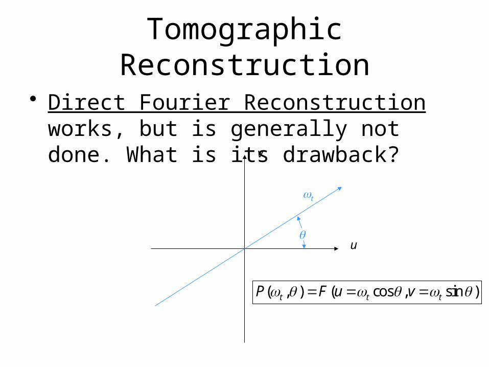
Tomographic Reconstruction
• Direct Fourier Reconstruction works, but is generally not done. What is its drawback?
( , ) ( cos , sin )t t tP F u v
u
v
q
wt

Tomographic Reconstruction
• This does tell us which angles we need for a full reconstruction. What is the rule?
( , ) ( cos , sin )t t tP F u v
u
v
q
wt

Tomographic Reconstruction
• Also, this proves that the Radon transform is an invertible transform (in the limit).
( , ) ( cos , sin )t t tP F u v
u
v
q
wt

Simple Backprojection
• Let’s try something else. What if we just cast the projections back across the image field?
1 2
3 4
4 6
3
7
4 6
3
7

Simple Backprojection
• A mathematical expression for simple backprojection
0
ˆ ( , ) ( cos sin , )sbpf x y p t x y d
Sum over the set of angles
The projection that intersects the given location of the image space
The estimate of the true image

Simple Backprojection
• Replace p by its 1D Fourier transform expression
• Which gives
0
ˆ ( , ) ( , ) tj tsbp t tf x y P e d d
( , ) ( , ) tj tt tp t P e d
With t related to x, y, and q as before

Simple Backprojection
• Rewrite in terms of x and y since t = ?
• This tells something about the property of our simple backprojection estimate in the frequency space. But what?
( cos sin )
0
ˆ ( , ) ( , ) tj x ysbp t tf x y P e d d

Simple Backprojection
• Any 2D function can be written in terms of its Fourier transform in polar coordinates
• This looks similar to our expression for the simple backprojection estimate.
( cos sin )
0
( , ) ( , ) rj x yr r rg x y G e d d

Simple Backprojection
• Compare these two– 2D FT of any function
– Simple backprojection estimate
( cos sin )
0
( , ) ( , ) rj x yr r rg x y G e d d
( cos sin )
0
ˆ ( , ) ( , ) tj x ysbp t tf x y P e d d
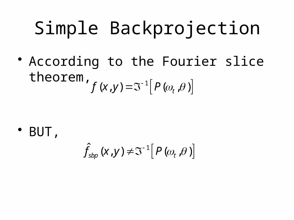
Simple Backprojection
• According to the Fourier slice theorem,
• BUT,
1ˆ ( , ) ( , )sbp tf x y P
1( , ) ( , )tf x y P

Simple Backprojection
• So, what is the simple backprojection estimate?
• Put it in the form of a 2D FT in polar coordinates
( cos sin )
0
ˆ ( , ) ( , ) tj x ysbp t tf x y P e d d
( cos sin )
0
( , )ˆ ( , ) tj x ytsbp t t
t
Pf x y e d d

Simple Backprojection
• An LSI system model for projection followed by simple backprojection:
FourierTransform
1
t
filter
InverseFourier
Transform
ˆ ( , )sbpf x y( , )f x y
ProjectionSimple
backprojectionˆ ( , )sbpf x y( , )f x y ( , )p t

Simple Backprojection
• The transfer function of that filter
, spatial frequencyt
resp
onse
2 2
1( )
1( , )
tt
H
H u vu v

Key Point
• Simple backprojection causes a loss of high-frequency details.– Drops off as the inverse of the spatial frequency

Simple Backprojection
• Example
True image Simple backprojection

Simple Backprojection
• Example
True image Simple backprojection

Simple Backprojection
• Example
True image Simple backprojection


