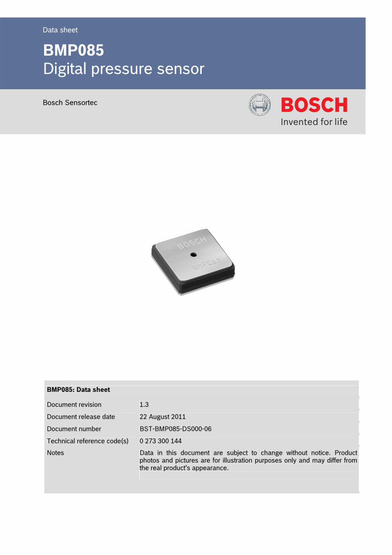
Data sheet BMP085 Digital pressure sensor Bosch Sensortec BMP085: Data sheet Document revision 1.3 Document release date 22 August 2011 Document number BST-BMP085-DS000-06 Technical reference code(s) 0 273 300 144 Notes Data in this document are subject to change without notice. Product photos and pictures are for illustration purposes only and may differ from the real product’s appearance.
Transcript
Data sheet
BMP085 Digital pressure sensor
Bosch Sensortec
BMP085: Data sheet
Document revision 1.3
Document release date 22 August 2011
Document number BST-BMP085-DS000-06
Technical reference code(s) 0 273 300 144
Notes Data in this document are subject to change without notice. Product photos and pictures are for illustration purposes only and may differ from the real product’s appearance.
Data sheet BMP085 Page 2
BST-BMP085-DS000-06 | Revision 1.3 | August 2011 Bosch Sensortec
• LCC8 package: Robust, ceramic lead-less chip carrier (LCC) package Small footprint: 5.0mm x 5.0mm Super-flat: 1.2mm height
• Low power: 5μA at 1 sample / sec. in standard mode
• Low noise: 0.06hPa (0.5m) in ultra low power mode
0.03hPa (0.25m) ultra high resolution mode down to 0.1m (rms noise) possible
• Temperature measurement included • I2C interface • Fully calibrated • Pb-free, halogen-free and RoHS compliant, • MSL 1
General Description
The BMP085 is the fully pin- and function compatible successor of the SMD500, a new generation of high precision digital pressure sensors for consumer applications. The universal C-code SMD500/BMP085 (“BMP085_SMD500_API”) is fully upward compatible to SMD500 and recognizes automatically the device ID. Customers already working with the SMD500 pressure sensor are invited to contact Bosch Sensortec as soon as they intend to switch-over to the BMP085 sensor for getting first-hand support. The ultra-low power, low voltage electronics of the BMP085 is optimized for use in mobile phones, PDAs, GPS navigation devices and outdoor equipment. With a low altitude noise of merely 0.25m at fast conversion time, the BMP085 offers superior performance. The I2C interface allows for easy system integration with a microcontroller. The BMP085 is based on piezo-resistive technology for EMC robustness, high accuracy and linearity as well as long term stability. Robert Bosch is the world market leader for pressure sensors in automotive applications. Based on the experience of over 200 million pressure sensors in the field, the BMP085 continues a new generation of micro-machined pressure sensors.
Data sheet BMP085 Page 3
BST-BMP085-DS000-06 | Revision 1.3 | August 2011 Bosch Sensortec
Note: Specifications within this document are subject to change without notice.
Typical applications
• Enhancement of GPS navigation (dead-reckoning, slope detection, etc.) • In- and out-door navigation • Leisure and sports • Weather forecast • Vertical velocity indication (rise/sink speed)
New features comparison BMP085 SMD500 Smaller package height 1.2mm 1.55mm Faster conversion time (standard mode each) 7.5ms (max.) 34ms Faster I2C data transfer max. 3.4MHz max. 400kHz Extended min. supply voltage min. 1.8V min. 2.2V Lower stand-by current (typ.) 0.1μA 0.7μA External clock not necessary necessary
Data sheet BMP085 Page 4
BST-BMP085-DS000-06 | Revision 1.3 | August 2011 Bosch Sensortec
5.2.1 TOP VIEW.................................................................................................................................. 21 5.2.2 TOP VIEW WITH LID .................................................................................................................... 22 5.2.3 SIDE VIEW WITH LID.................................................................................................................... 22
Note: Specifications within this document are subject to change without notice.
3. Operation
3.1 General description
The BMP085 is designed to be connected directly to a microcontroller of a mobile device via the I2C bus. The pressure and temperature data has to be compensated by the calibration data of the E2PROM of the BMP085.
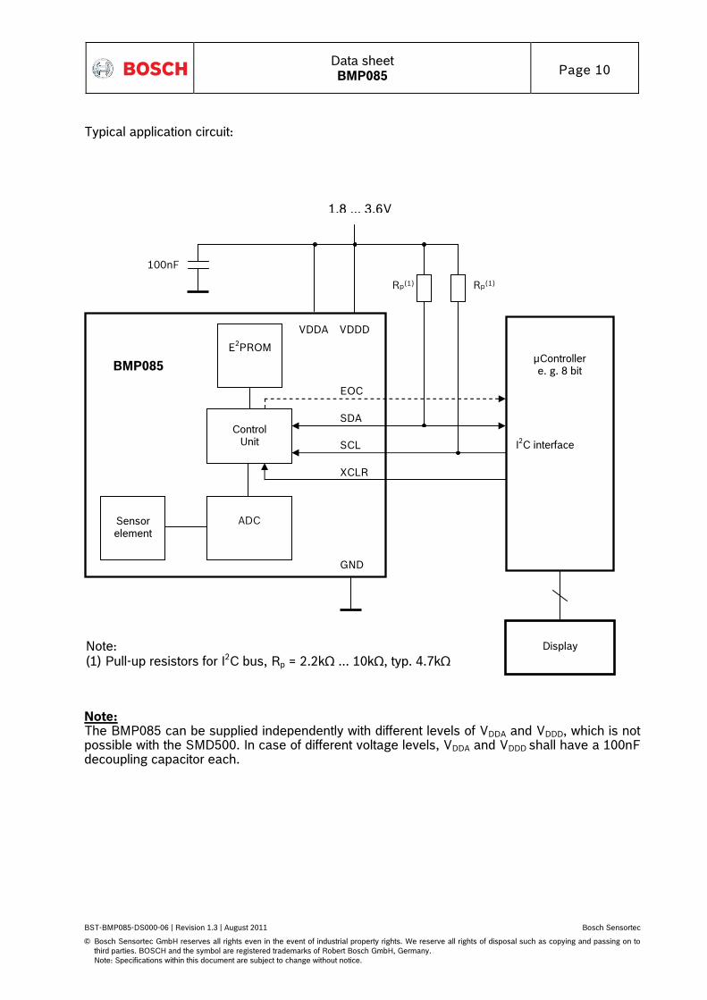
3.2 General function and application schematics
The BMP085 consists of a piezo-resistive sensor, an analog to digital converter and a control unit with E2PROM and a serial I2C interface. The BMP085 delivers the uncompensated value of pressure and temperature. The E2PROM has stored 176 bit of individual calibration data. This is used to compensate offset, temperature dependence and other parameters of the sensor.
• UP = pressure data (16 to 19 bit) • UT = temperature data (16 bit)
Data sheet BMP085 Page 10
BST-BMP085-DS000-06 | Revision 1.3 | August 2011 Bosch Sensortec
Note: Specifications within this document are subject to change without notice.
Typical application circuit: 1.8 ... 3.6V
Note: (1) Pull-up resistors for I2C bus, Rp = 2.2kΩ ... 10kΩ, typ. 4.7kΩ
Sensor element
E2PROM
ADC
Control Unit
BMP085
SCL
SDA
GND
VDDD
Rp(1) Rp(1)
XCLR
Display
100nF
VDDA
EOC
μController
e. g. 8 bit
I2C interface Note: The BMP085 can be supplied independently with different levels of VDDA and VDDD, which is not possible with the SMD500. In case of different voltage levels, VDDA and VDDD shall have a 100nF decoupling capacitor each.
Data sheet BMP085 Page 11
BST-BMP085-DS000-06 | Revision 1.3 | August 2011 Bosch Sensortec
Note: Specifications within this document are subject to change without notice.
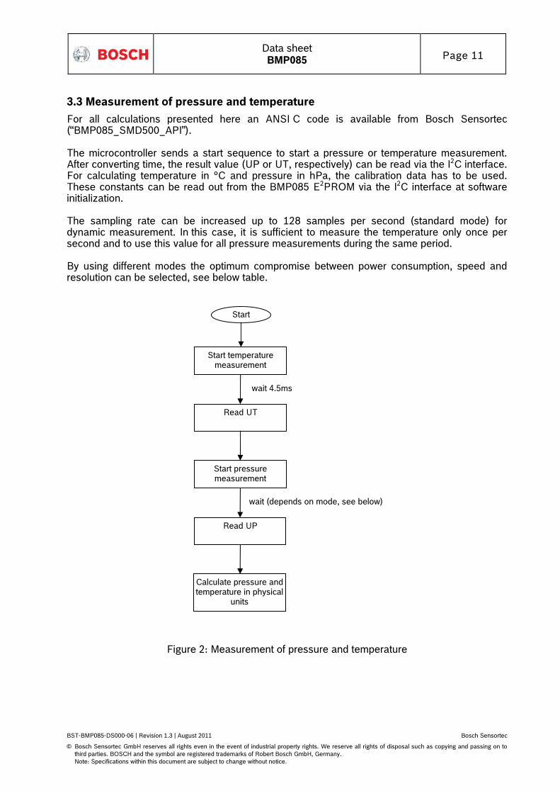
3.3 Measurement of pressure and temperature
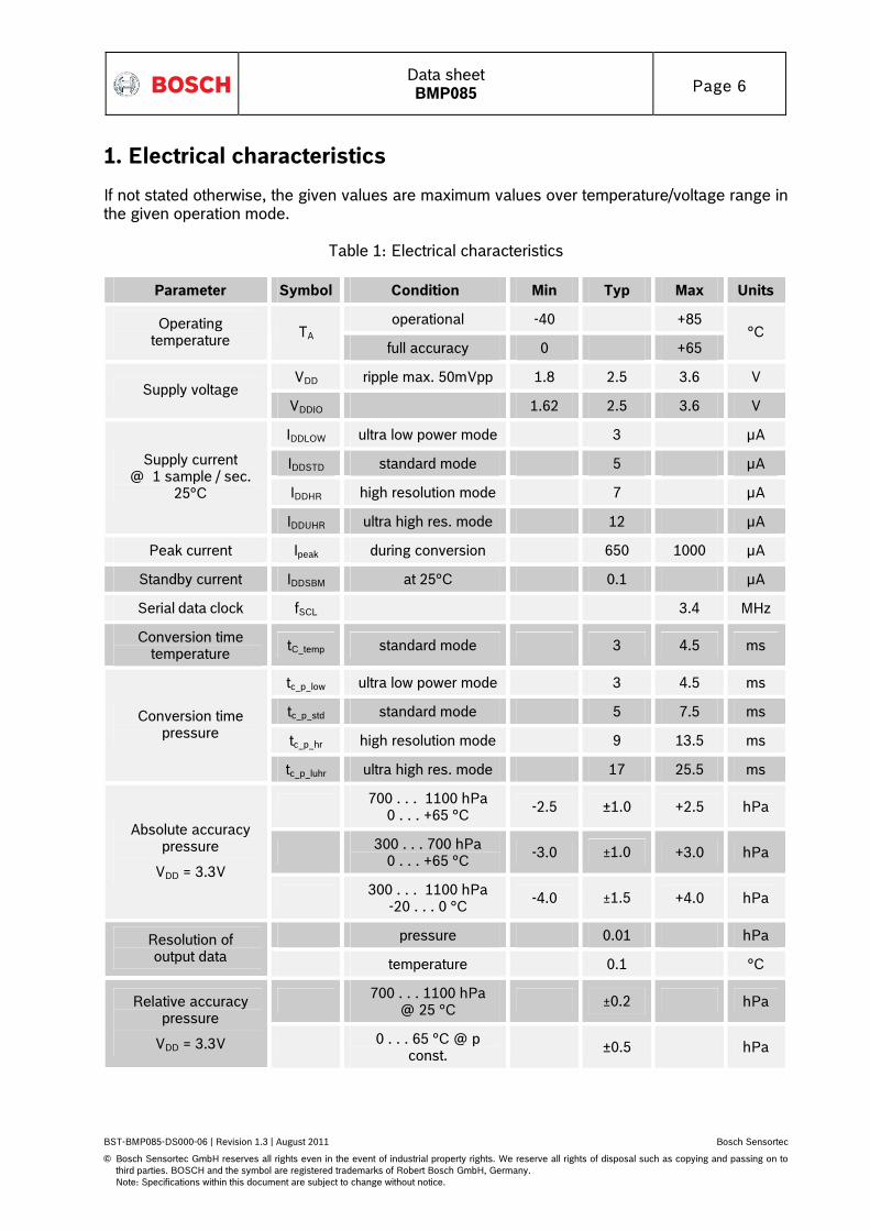
For all calculations presented here an ANSI C code is available from Bosch Sensortec (“BMP085_SMD500_API”). The microcontroller sends a start sequence to start a pressure or temperature measurement. After converting time, the result value (UP or UT, respectively) can be read via the I2C interface. For calculating temperature in °C and pressure in hPa, the calibration data has to be used. These constants can be read out from the BMP085 E2PROM via the I2C interface at software initialization. The sampling rate can be increased up to 128 samples per second (standard mode) for dynamic measurement. In this case, it is sufficient to measure the temperature only once per second and to use this value for all pressure measurements during the same period. By using different modes the optimum compromise between power consumption, speed and resolution can be selected, see below table.
Start temperature measurement
Read UT
Start pressure measurement
Read UP
Start
Calculate pressure and temperature in physical
units
wait 4.5ms wait (depends on mode, see below)
Figure 2: Measurement of pressure and temperature
Data sheet BMP085 Page 12
BST-BMP085-DS000-06 | Revision 1.3 | August 2011 Bosch Sensortec
Note: Specifications within this document are subject to change without notice.
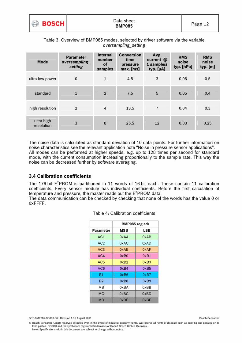
Table 3: Overview of BMP085 modes, selected by driver software via the variable oversampling_setting
Mode Parameter
oversampling_setting
Internal number
of samples
Conversion time
pressure max. [ms]
Avg. current @ 1 sample/s
typ. [μA]
RMS noise
typ. [hPa]
RMS noise
typ. [m]
ultra low power 0 1 4.5 3 0.06 0.5
standard
1
2 7.5 5 0.05 0.4
high resolution
2
4 13.5 7 0.04 0.3
ultra high resolution
3
8 25.5 12 0.03 0.25
The noise data is calculated as standard deviation of 10 data points. For further information on noise characteristics see the relevant application note “Noise in pressure sensor applications”. All modes can be performed at higher speeds, e.g. up to 128 times per second for standard mode, with the current consumption increasing proportionally to the sample rate. This way the noise can be decreased further by software averaging.
3.4 Calibration coefficients
The 176 bit E2PROM is partitioned in 11 words of 16 bit each. These contain 11 calibration coefficients. Every sensor module has individual coefficients. Before the first calculation of temperature and pressure, the master reads out the E2PROM data. The data communication can be checked by checking that none of the words has the value 0 or 0xFFFF.
Table 4: Calibration coefficients
BMP085 reg adr
Parameter MSB LSB
AC1 0xAA 0xAB
AC2 0xAC 0xAD
AC3 0xAE 0xAF
AC4 0xB0 0xB1
AC5 0xB2 0xB3
AC6 0xB4 0xB5
B1 0xB6 0xB7
B2 0xB8 0xB9
MB 0xBA 0xBB
MC 0xBC 0xBD
MD 0xBE 0xBF
Data sheet BMP085 Page 13
BST-BMP085-DS000-06 | Revision 1.3 | August 2011 Bosch Sensortec
Note: Specifications within this document are subject to change without notice.
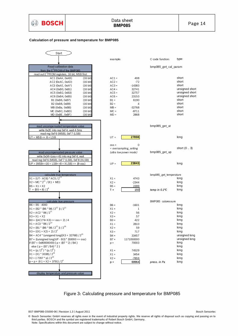
3.5 Calculation pressure and temperature
The mode (ultra low power, standard, high, ultra high resolution) can be selected by the variable oversampling_setting (0, 1, 2, 3) in the C code. The universal code SMD500/BMP085 is fully upward compatible to SMD500 and recognizes automatically the device ID. Thus, the SMD500 can be replaced "on the fly" by the BMP085 without changing hardware or software. Calculation of true temperature and pressure in steps of 1Pa (= 0.01hPa = 0.01mbar) and temperature in steps of 0.1°C. The following figure shows the detailed algorithm for pressure and temperature measurement. This algorithm is available to customers as reference C source code (“BMP085_SMD500_API”) from Bosch Sensortec and via its sales and distribution partners. Please contact your Bosch Sensortec representative for details.
Data sheet BMP085 Page 14
BST-BMP085-DS000-06 | Revision 1.3 | August 2011 Bosch Sensortec
Note: Specifications within this document are subject to change without notice.
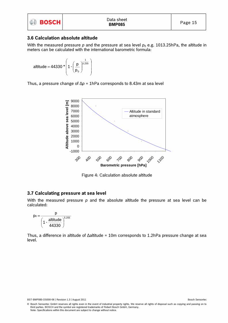
3.6 Calculation absolute altitude
With the measured pressure p and the pressure at sea level p0 e.g. 1013.25hPa, the altitude in meters can be calculated with the international barometric formula:
=
5.255
1
0p
p -1 * 44330 altitude
Thus, a pressure change of ∆p = 1hPa corresponds to 8.43m at sea level
-10000
100020003000400050006000700080009000
300
400
500
600
700
800
900
1000
1100
Barometric pressure [hPa]
Alti
tude
abo
ve s
ea le
vel [
m]
Altitude in standardatmosphere
Figure 4: Calculation absolute altitude
3.7 Calculating pressure at sea level
With the measured pressure p and the absolute altitude the pressure at sea level can be calculated:
255.50
44330
altitude - 1
p p
=
Thus, a difference in altitude of ∆altitude = 10m corresponds to 1.2hPa pressure change at sea level.
Data sheet BMP085 Page 16
BST-BMP085-DS000-06 | Revision 1.3 | August 2011 Bosch Sensortec
Note: Specifications within this document are subject to change without notice.
4. I²C Interface
• I²C is a digital two wire interface • Clock frequencies up to 3.4mBit/sec (I²C standard, fast and high-speed mode supported) • SCL and SDA needs a pull-up resistor, typ. 4.7 kOhm to VDDD (one resistor each for all
the I²C bus)
The I2C bus is used to control the sensor, to read calibration data from the E2PROM and to read the measurement data when A/D conversion is finished. SDA (serial data) and SCL (serial clock) have open-drain outputs. For detailed I2C-bus specification please refer to: http://www.nxp.com/acrobat_download/literature/9398/39340011.pdf The BMP085 has a master clear (XCLR) low-active input that is used to reset the BMP085 and initializes internal registers and counters. The device is automatically reset by power on reset (POR) circuitry. XCLR can be left floating if not used. The pad has an internal pull-up resistor of typ. 120kOhm.
4.1 I²C specification
Table 5: Electrical parameters for the I2C interface
Parameter Symbol Min. Typ Max. Units
Clock input frequency fSCL 3.4 MHz
Input-low level VIL 0 0.2 * VDDD V
Input-high level VIH 0.8 * VDDD VDDD V
SDA and SCL pull-up resistor Rpull-up 2.2 10 kOhm
SDA sink current @ VDDD = 1.62V, VOL = 0.3V
ISDA_sink 9 mA
EOC sink current @ VDDD = 1.62V, VOL = 0.3V
ISDA_sink 7.7 mA
EOC source current @ VDDD = 1.62V, VOH = 1.32V
ISDA_source 1.5 mA
XCLR pulse length tXCLR 1 μs
Start-up time after power-up, before first communication
Note: Specifications within this document are subject to change without notice.
4.2 Device and register address
The BMP085 module address is shown below. The LSB of the device address distinguishes between read (1) and write (0) operation, corresponding to address 0xEF (read) and 0xEE (write).
A7 A6 A5 A4 A3 A2 A1 W/R 1 1 1 0 1 1 1 0/1
There is an easy way to connect two BMP085 to the same I2C bus: You can use the XCLR input of BMP085 to set one BMP085 part silent while you communicate with the other BMP085 part via I2C and vice versa. The signals can be provided by two digital outputs of the microcontroller, or one digital output and one inverter.
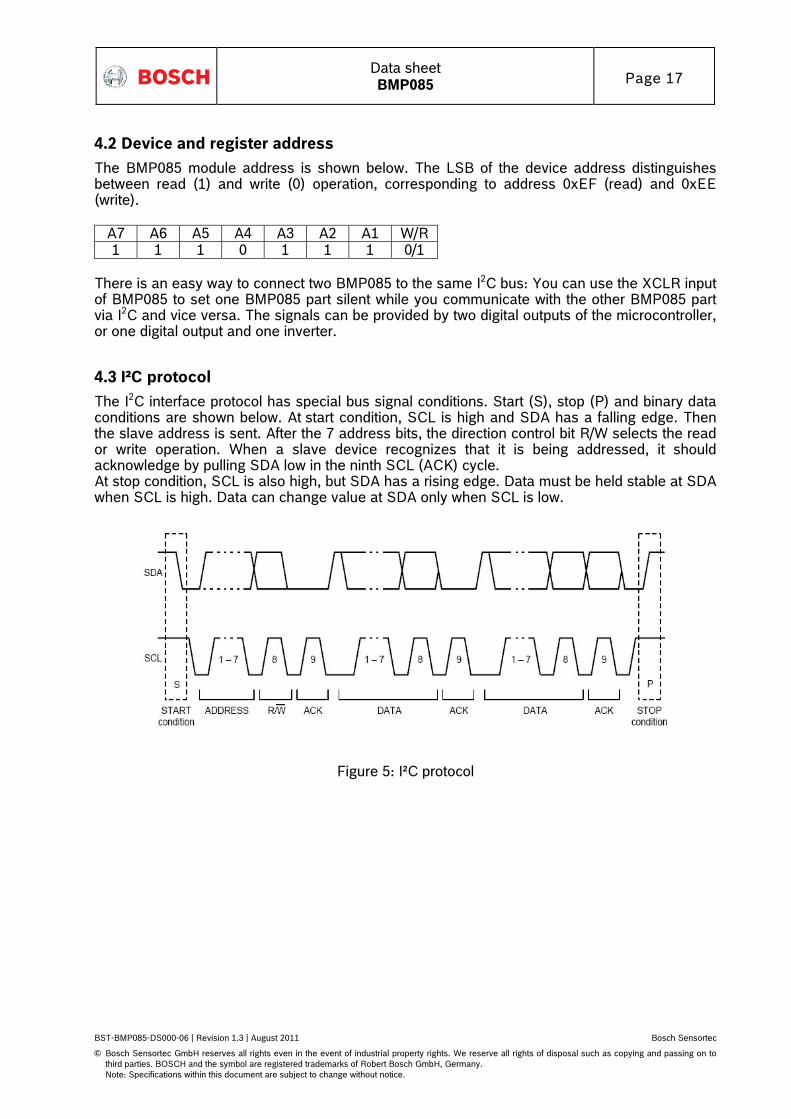
4.3 I²C protocol
The I2C interface protocol has special bus signal conditions. Start (S), stop (P) and binary data conditions are shown below. At start condition, SCL is high and SDA has a falling edge. Then the slave address is sent. After the 7 address bits, the direction control bit R/W selects the read or write operation. When a slave device recognizes that it is being addressed, it should acknowledge by pulling SDA low in the ninth SCL (ACK) cycle. At stop condition, SCL is also high, but SDA has a rising edge. Data must be held stable at SDA when SCL is high. Data can change value at SDA only when SCL is low.
Figure 5: I²C protocol
Data sheet BMP085 Page 18
BST-BMP085-DS000-06 | Revision 1.3 | August 2011 Bosch Sensortec
Note: Specifications within this document are subject to change without notice.
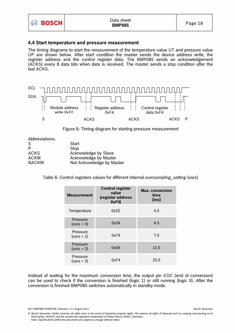
4.4 Start temperature and pressure measurement
The timing diagrams to start the measurement of the temperature value UT and pressure value UP are shown below. After start condition the master sends the device address write, the register address and the control register data. The BMP085 sends an acknowledgement (ACKS) every 8 data bits when data is received. The master sends a stop condition after the last ACKS.
ACKS S ACKS
Module address write 0xEE
Register address 0xF4
Control register data 0xF4
SCL
SDA
ACKS P
Figure 6: Timing diagram for starting pressure measurement
Abbreviations: S Start P Stop ACKS Acknowledge by Slave ACKM Acknowledge by Master NACKM Not Acknowledge by Master
Table 6: Control registers values for different internal oversampling_setting (osrs)
Measurement
Control register value
(register address 0xF4)
Max. conversion time [ms]
Temperature 0x2E 4.5
Pressure (osrs = 0) 0x34 4.5
Pressure (osrs = 1) 0x74 7.5
Pressure (osrs = 2) 0xB4 13.5
Pressure (osrs = 3) 0xF4 25.5
Instead of waiting for the maximum conversion time, the output pin EOC (end of conversion) can be used to check if the conversion is finished (logic 1) or still running (logic 0). After the conversion is finished BMP085 switches automatically in standby mode.
Data sheet BMP085 Page 19
BST-BMP085-DS000-06 | Revision 1.3 | August 2011 Bosch Sensortec
Note: Specifications within this document are subject to change without notice.
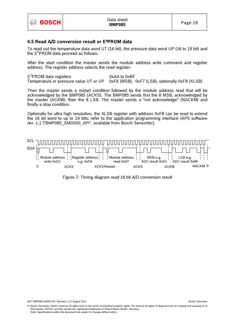
4.5 Read A/D conversion result or E²PROM data
To read out the temperature data word UT (16 bit), the pressure data word UP (16 to 19 bit) and the E2PROM data proceed as follows: After the start condition the master sends the module address write command and register address. The register address selects the read register: E2PROM data registers 0xAA to 0xBF Temperature or pressure value UT or UP 0xF6 (MSB), 0xF7 (LSB), optionally 0xF8 (XLSB) Then the master sends a restart condition followed by the module address read that will be acknowledged by the BMP085 (ACKS). The BMP085 sends first the 8 MSB, acknowledged by the master (ACKM), then the 8 LSB. The master sends a "not acknowledge" (NACKM) and finally a stop condition. Optionally for ultra high resolution, the XLSB register with address 0xF8 can be read to extend the 16 bit word to up to 19 bits; refer to the application programming interface (API) software rev. 1.1 (“BMP085_SMD500_API”, available from Bosch Sensortec).
S ACKS
Module address write 0xEE
ACKS
Register addresse.g. 0xF6
MSB e.g. ADC result 0x5C
ACKS
Module addressread 0xEF
Restart ACKM
LSB e.g. ADC result 0x96
NACKM
SCL
SDA
P
Figure 7: Timing diagram read 16 bit A/D conversion result
Data sheet BMP085 Page 20
BST-BMP085-DS000-06 | Revision 1.3 | August 2011 Bosch Sensortec
Note: Specifications within this document are subject to change without notice.
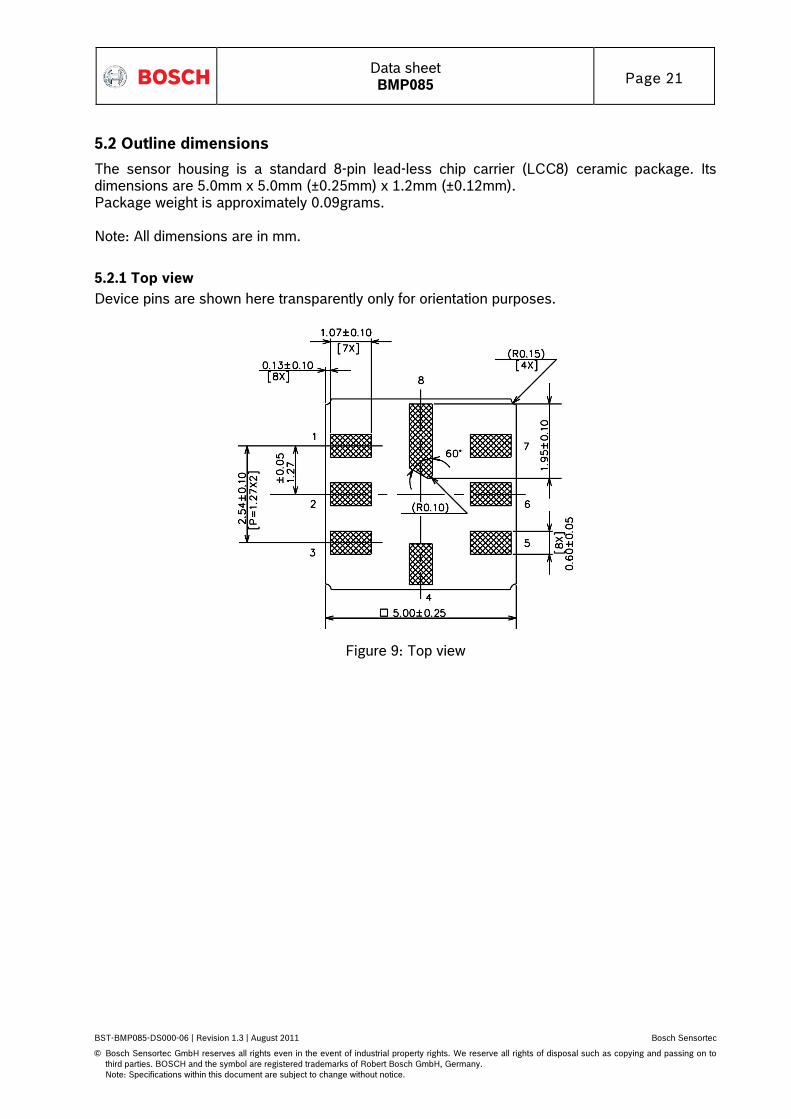
5.2 Outline dimensions
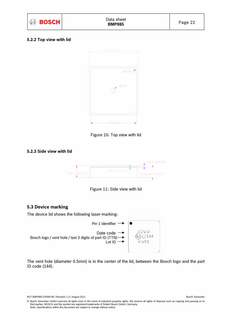
The sensor housing is a standard 8-pin lead-less chip carrier (LCC8) ceramic package. Its dimensions are 5.0mm x 5.0mm (±0.25mm) x 1.2mm (±0.12mm). Package weight is approximately 0.09grams. Note: All dimensions are in mm.
5.2.1 Top view
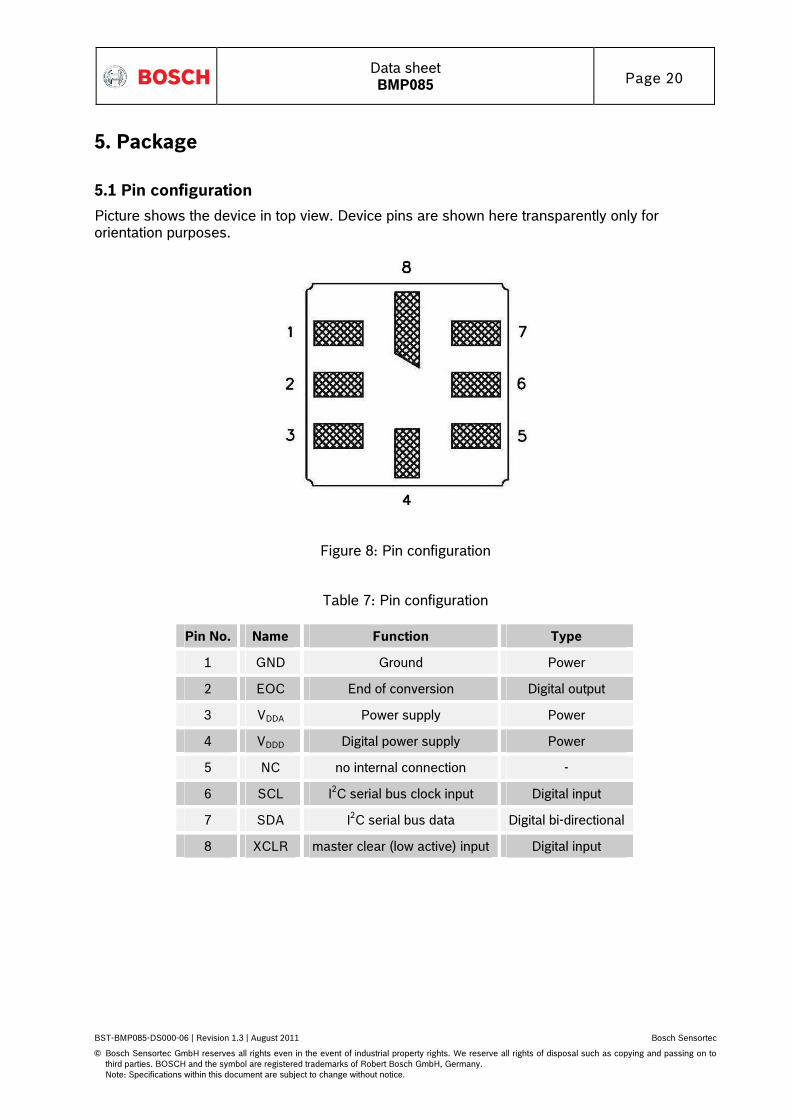
Device pins are shown here transparently only for orientation purposes.
Figure 9: Top view
Data sheet BMP085 Page 22
BST-BMP085-DS000-06 | Revision 1.3 | August 2011 Bosch Sensortec
Note: Specifications within this document are subject to change without notice.
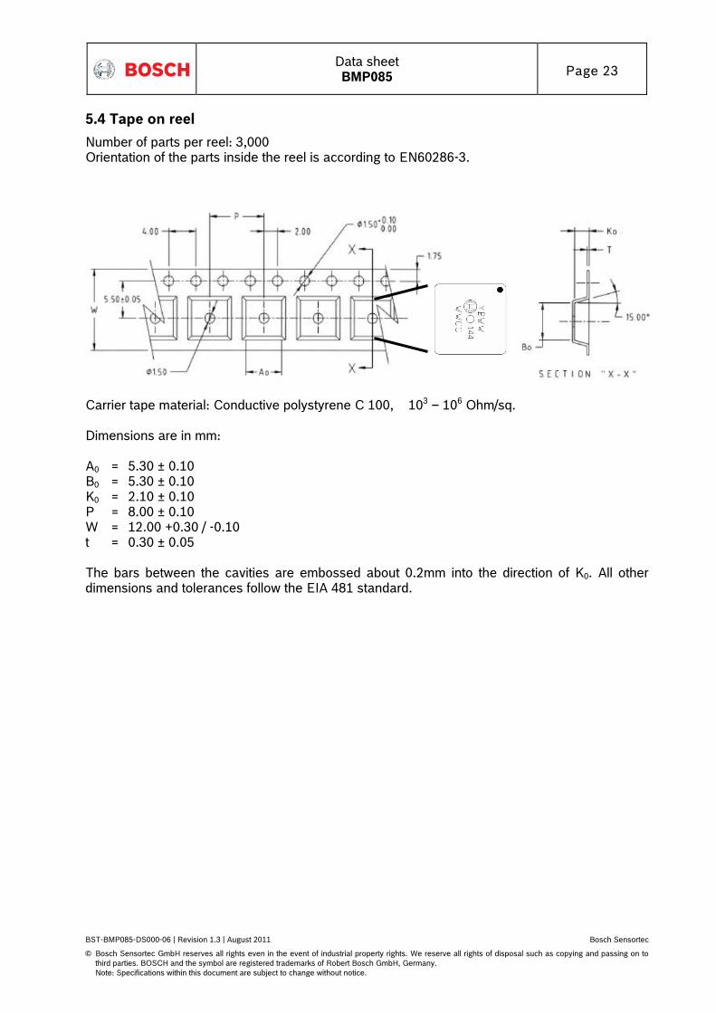
5.4 Tape on reel
Number of parts per reel: 3,000 Orientation of the parts inside the reel is according to EN60286-3.
Carrier tape material: Conductive polystyrene C 100, 103 – 106 Ohm/sq. Dimensions are in mm: A0 = 5.30 ± 0.10 B0 = 5.30 ± 0.10 K0 = 2.10 ± 0.10 P = 8.00 ± 0.10 W = 12.00 +0.30 / -0.10 t = 0.30 ± 0.05 The bars between the cavities are embossed about 0.2mm into the direction of K0. All other dimensions and tolerances follow the EIA 481 standard.
Data sheet BMP085 Page 24
BST-BMP085-DS000-06 | Revision 1.3 | August 2011 Bosch Sensortec
Note: Specifications within this document are subject to change without notice.
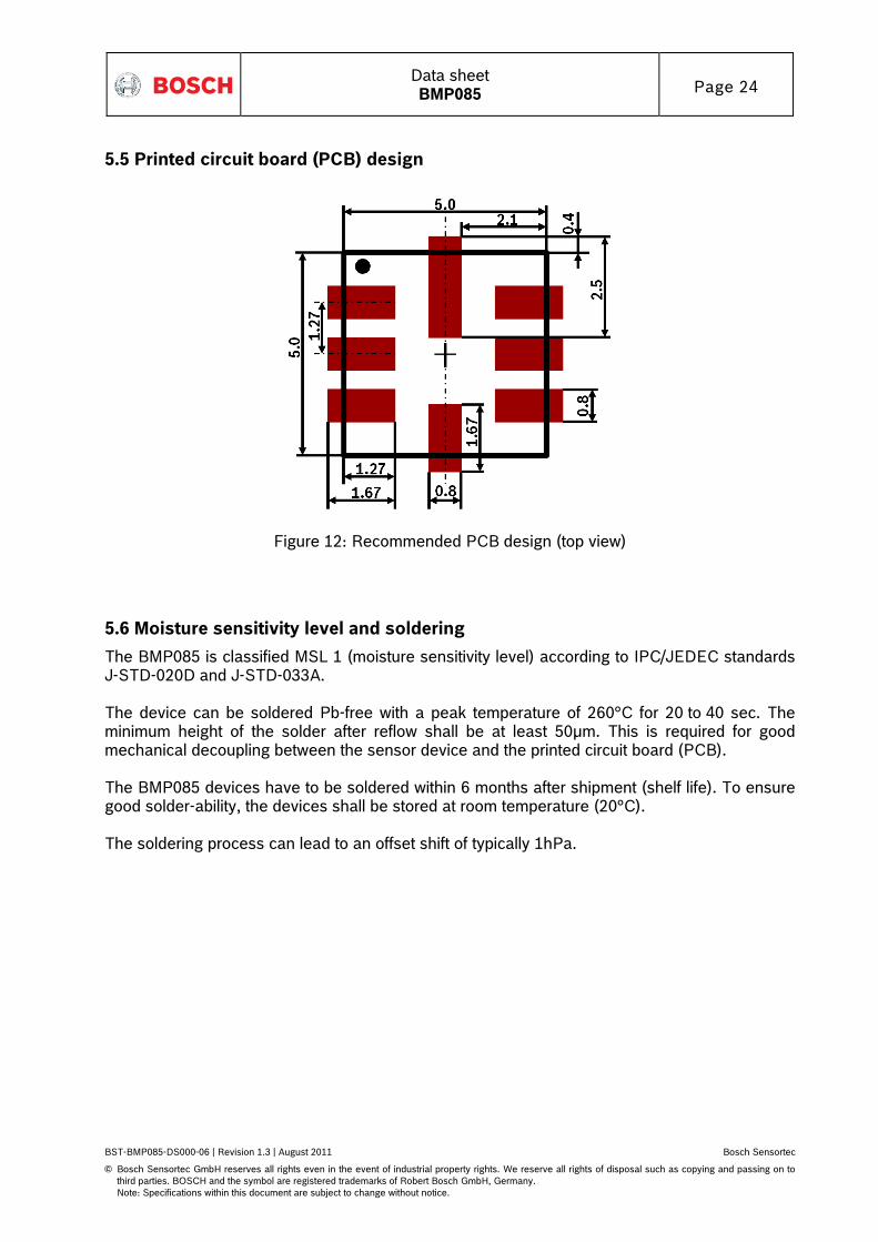
5.5 Printed circuit board (PCB) design
Figure 12: Recommended PCB design (top view)
5.6 Moisture sensitivity level and soldering
The BMP085 is classified MSL 1 (moisture sensitivity level) according to IPC/JEDEC standards J-STD-020D and J-STD-033A. The device can be soldered Pb-free with a peak temperature of 260°C for 20 to 40 sec. The minimum height of the solder after reflow shall be at least 50μm. This is required for good mechanical decoupling between the sensor device and the printed circuit board (PCB). The BMP085 devices have to be soldered within 6 months after shipment (shelf life). To ensure good solder-ability, the devices shall be stored at room temperature (20°C). The soldering process can lead to an offset shift of typically 1hPa.
Data sheet BMP085 Page 25
BST-BMP085-DS000-06 | Revision 1.3 | August 2011 Bosch Sensortec
Note: Specifications within this document are subject to change without notice.
5.7 RoHS compliancy
The BMP085 sensor meets the requirements of the EC directive "Restriction of hazardous substances (RoHS)", please refer also to: "Directive 2002/95/EC of the European Parliament and of the Council of 27 January 2003 on the restriction of the use of certain hazardous substances in electrical and electronic equipment". The BMP085 sensor is also halogen-free. Please contact your Bosch Sensortec representative for the corresponding analysis report.
5.8 Mounting and assembly recommendations
Please read the following recommendations carefully.
• The clearance above the metal lid shall be 0.1mm at minimum
• For the device housing appropriate venting needs to be provided in case the ambient pressure shall be measured; if waterproof packaging is needed, venting can be accomplished by a vent element with a membrane like Gore-Tex(TM)
• Liquids shall not come into direct contact with the device
• During operation the sensor is sensitive to light, which can influence the accuracy of the
measurement (photo-current of silicon); therefore, the hole in the top lid shall not be exposed to direct light during operation
• The BMP085 shall not the placed close the fast heating parts. In case of gradients
> 3°C/sec. it is recommended to follow Bosch Sensortec application note ANP015, "Correction of errors induced by fast temperature changes"; please contact your Bosch Sensortec representative for details
• For further details, please refer to the BMP085 handling, soldering & mounting
instructions manual that is also available from Bosch Sensortec
Data sheet BMP085 Page 26
BST-BMP085-DS000-06 | Revision 1.3 | August 2011 Bosch Sensortec
Note: Specifications within this document are subject to change without notice.
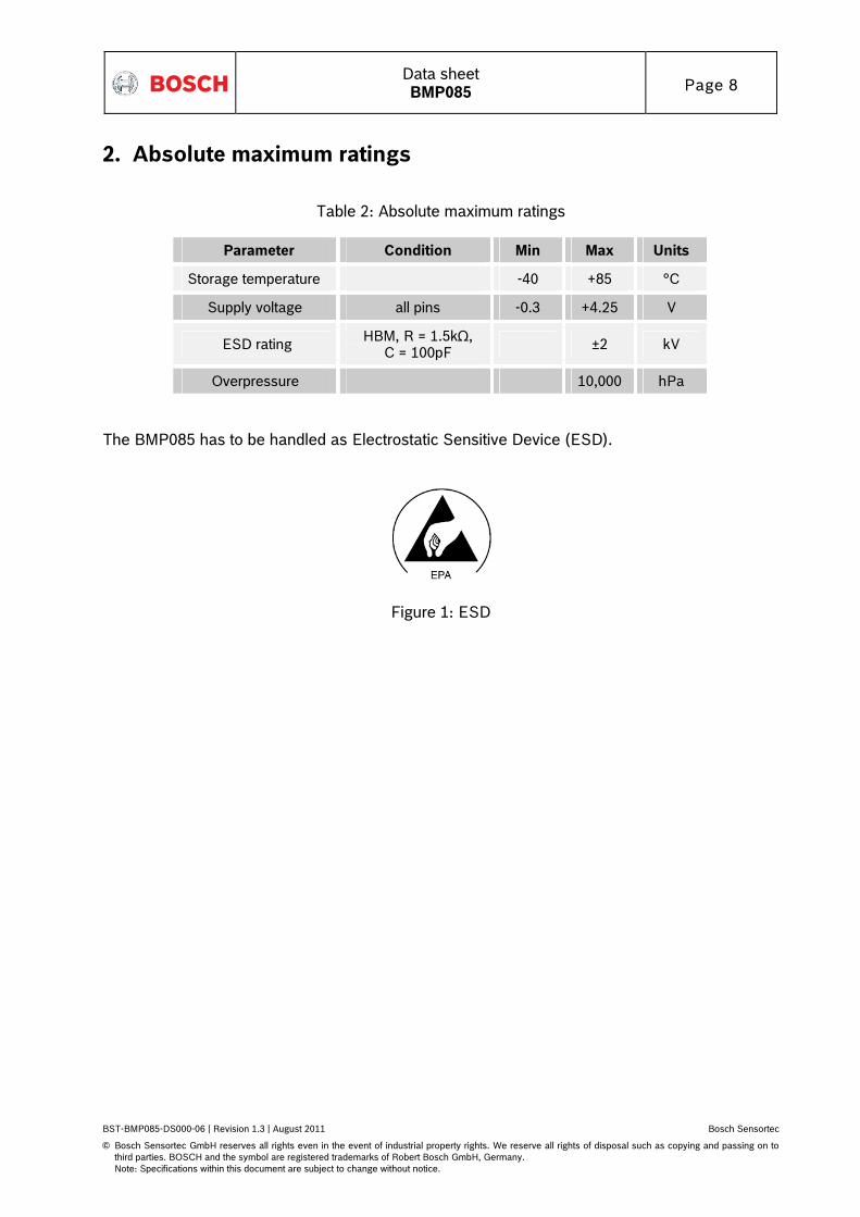
6. Legal disclaimer
6.1 Engineering samples
Engineering Samples are marked with an asterisk (*) or (e) or (E). Samples may vary from the valid technical specifications of the product series contained in this data sheet. They are therefore not intended or fit for resale to third parties or for use in end products. Their sole purpose is internal client testing. The testing of an engineering sample may in no way replace the testing of a product series. Bosch Sensortec assumes no liability for the use of engineering samples. The Purchaser shall indemnify Bosch Sensortec from all claims arising from the use of engineering samples.
6.2 Product use
Bosch Sensortec products are developed for the consumer goods industry. They may only be used within the parameters of this product data sheet. They are not fit for use in life-sustaining or security sensitive systems. Security sensitive systems are those for which a malfunction is expected to lead to bodily harm or significant property damage. In addition, they are not fit for use in products which interact with motor vehicle systems. The resale and/or use of products are at the purchaser’s own risk and his own responsibility. The examination of fitness for the intended use is the sole responsibility of the Purchaser. The purchaser shall indemnify Bosch Sensortec from all third party claims arising from any product use not covered by the parameters of this product data sheet or not approved by Bosch Sensortec and reimburse Bosch Sensortec for all costs in connection with such claims. The purchaser must monitor the market for the purchased products, particularly with regard to product safety, and inform Bosch Sensortec without delay of all security relevant incidents.
6.3 Application examples and hints
With respect to any examples or hints given herein, any typical values stated herein and/or any information regarding the application of the device, Bosch Sensortec hereby disclaims any and all warranties and liabilities of any kind, including without limitation warranties of non-infringement of intellectual property rights or copyrights of any third party. The information given in this document shall in no event be regarded as a guarantee of conditions or characteristics. They are provided for illustrative purposes only and no evaluation regarding infringement of intellectual property rights or copyrights or regarding functionality, performance or error has been made.
Data sheet BMP085 Page 27
BST-BMP085-DS000-06 | Revision 1.3 | August 2011 Bosch Sensortec
Note: Specifications within this document are subject to change without notice.
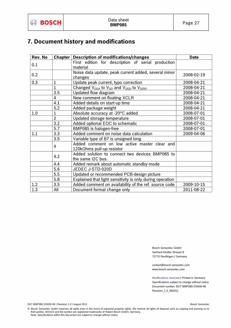
7. Document history and modifications
Rev. No Chapter Description of modifications/changes Date
0.1 First edition for description of serial production material
0.2 Noise data update, peak current added, several minor changes
2008-02-19
0.3 1 Update peak current, typo correction 2008-04-21 1 Changed VDDA to VDD and VDDD to VDDIO 2008-04-21 3.5 Updated flow diagram 2008-04-21 4 New comment on floating XCLR 2008-04-21 4.1 Added details on start-up time 2008-04-21 5.2 Added package weight 2008-04-21 1.0 1 Absolute accuracy at -20°C added 2008-07-01 2 Updated storage temperature 2008-07-01 3.2 Added optional EOC to schematic 2008-07-01 5.7 BMP085 is halogen-free 2008-07-01 1.1 3.3 Added comment on noise data calculation 2009-04-06 3.5 Variable type of B7 is unsigned long
4 Added comment on low active master clear and 120kOhms pull-up resistor
4.2 Added solution to connect two devices BMP085 to the same I2C bus.
4.4 Added remark about automatic standby-mode 5.6 JEDEC J-STD-020D 5.5 Updated or recommended PCB-design picture 5.8 Explained that light sensitivity is only during operation 1.2 3.5 Added comment on availability of the ref. source code 2009-10-15 1.3 All Document format change only 2011-08-22