2
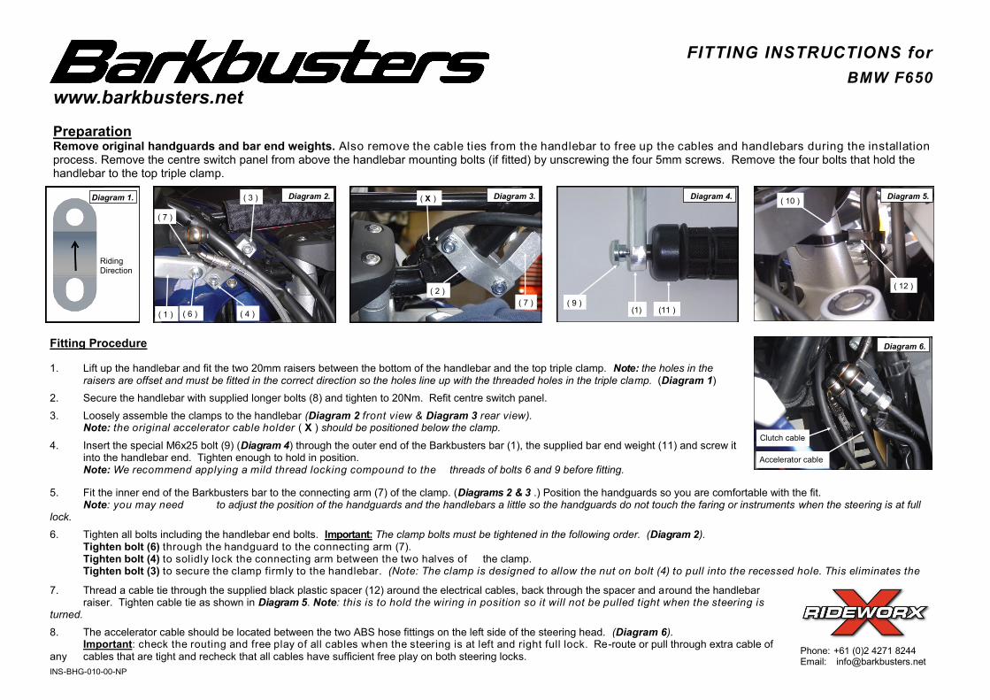
www.barkbusters.net FITTING INSTRUCTIONS for BMW F650 Phone: +61 (0)2 4271 8244 Email: [email protected] Preparation Remove original handguards and bar end weights. Also remove the cable ties from the handlebar to free up the cables and handlebars during the installation process. Remove the centre switch panel from above the handlebar mounting bolts (if fitted) by unscrewing the four 5mm screws. Remove the four bolts that hold the handlebar to the top triple clamp. Fitting Procedure 1. Lift up the handlebar and fit the two 20mm raisers between the bottom of the handlebar and the top triple clamp. Note: the holes in the raisers are offset and must be fitted in the correct direction so the holes line up with the threaded holes in the triple clamp. (Diagram 1) 2. Secure the handlebar with supplied longer bolts (8) and tighten to 20Nm. Refit centre switch panel. 3. Loosely assemble the clamps to the handlebar (Diagram 2 front view & Diagram 3 rear view). Note: the original accelerator cable holder ( X ) should be positioned below the clamp. 4. Insert the special M6x25 bolt (9) (Diagram 4) through the outer end of the Barkbusters bar (1), the supplied bar end weight (11) and screw it into the handlebar end. Tighten enough to hold in position. Note: We recommend applying a mild thread locking compound to the threads of bolts 6 and 9 before fitting. 7. Thread a cable tie through the supplied black plastic spacer (12) around the electrical cables, back through the spacer and around the handlebar raiser. Tighten cable tie as shown in Diagram 5. Note: this is to hold the wiring in position so it will not be pulled tight when the steering is turned. 8. The accelerator cable should be located between the two ABS hose fittings on the left side of the steering head. (Diagram 6). Important: check the routing and free play of all cables when the steering is at left and right full lock. Re-route or pull through extra cable of any cables that are tight and recheck that all cables have sufficient free play on both steering locks. Diagram 4. (11 ) (1) ( 9 ) ( 6 ) ( 1 ) ( 3 ) ( 7 ) ( 4 ) Accelerator cable Clutch cable 5. Fit the inner end of the Barkbusters bar to the connecting arm (7) of the clamp. (Diagrams 2 & 3 .) Position the handguards so you are comfortable with the fit. Note: you may need to adjust the position of the handguards and the handlebars a little so the handguards do not touch the faring or instruments when the steering is at full lock. 6. Tighten all bolts including the handlebar end bolts. Important: The clamp bolts must be tightened in the following order. (Diagram 2). Tighten bolt (6) through the handguard to the connecting arm (7). Tighten bolt (4) to solidly lock the connecting arm between the two halves of the clamp. Tighten bolt (3) to secure the clamp firmly to the handlebar. (Note: The clamp is designed to allow the nut on bolt (4) to pull into the recessed hole. This eliminates the ( 12 ) ( 10 ) ( X ) ( 7 ) ( 2 ) Diagram 1. Riding Direction Diagram 3. Diagram 2. Diagram 5. Diagram 6. INS-BHG-010-00-NP