BULLETIN OF THE POLISH ACADEMY OF SCIENCES TECHNICAL SCIENCES Vol. 54, No. 2, 2006 BN-based nano-composites obtained by pulsed laser deposition B. MAJOR 1* , W. MRÓZ 2 , M. JELINEK 3 , R. KOSYDAR 1 , M. KOT 4 , L. MAJOR 1 , S. BURDY ´ NSKA 2 , and R. KUSTOSZ 5 1 Institute of Metallurgy and Materials Science, Polish Academy of Sciences, 30-059 Cracow, 25 Reymonta St., Poland 2 Institute of Optoelectronics, Military University of Technology, 01-483 Warsaw, 2 Kaliski St., Poland 3 Institute of Physics, Academy of Science of the Czech Republic, Prague 8, Na Slovance 2, Czech Republic 4 Tribology and Surface Engineering Laboratory, AGH University of Science and Technology, 30 Mickiewicza Ave, 30-059 Cracow, Poland 5 Foundation of Cardiac Surgery Development, 345a Wolnosci St., 41-800 Zabrze, Poland Abstract. Boron nitride thin layers were produced by means of the pulsed laser deposition technique from hexagonal boron nitride target. Two types of laser i.e. Nd:YAG with Q-switch as well as KrF coupled with RF generator were used. Influence of deposition parameters on surface morphology, phase composition as well as mechanical properties is discussed. Results obtained using Fourier Transformed Infrared Spectroscopy, Transmission and Scanning Electron Microscopy, Atomic Force Microscopy are presented. Micromechanical properties mea- sured during microindentation, scratch and wear tests are also shown. Key words: boron nitride, pulsed laser deposition, coatings, nano-composites. 1. Introduction Boron nitride (BN) is a chemical compound which is isoelec- tronic and isostructural with carbon. BN phases can be di- vided according to the bond hybridization into: sp 2 -types i.e. a hexagonal h-BN, turbostratic t-BN and rhombohedral r-BN phases, with the structure and properties close to graphite, and sp 3 -types – cubic c-BN and wurtzite w-BN forms, sim- ilar to diamond and lonsdaleite, respectively. All types of BN are chemically inert and corrosion-resistant insulators but good thermal conductors. Moreover, h-BN and r-BN phases are very soft, characterized by lubricating abilities similar to graphite. The cubic c-BN phase is characterized by high hardness, good abrasion resistance, high melting point and oxidation resis- tance at higher temperature, and practically no reactivity with iron group metals. The properties of w-BN are very close to the c-BN ones. Layers with c-BN or w-BN can be used as abra- sion resistant tribological coatings as well as corrosion resis- tant ones protecting construction elements against chemically- aggressive environments and high temperature. They may also work as semiconducting layers. The h-BN and r-BN coatings can be used as anti-corrosion coatings and lubricating layers. Both sp 3 - and sp 2 -type phases may be applied as composites combining advantages of both soft and hard phases [1, 2]. This work is aimed at obtaining of nano-composite coat- ings based on BN-type phases, which could be used for special purposes as a lubricating tribological layer. 2. Experimental Boron nitride thin films were obtained by ablation of the com- mercial h-BN target by means of a PLD deposition system. Two types of PLD apparatus were used: 1. The Nd:YAG laser with Q-switch operating in pulse mode (wavelength λ = 1064 nm, pulse duration τ = 10 ns, frequency f = 10 Hz, beam energy E = 0,6 J) was applied. Deposition was performed in an atmosphere of nitrogen, argon or in a mix- ture of nitrogen and argon. Austenitic steel or ferritic-austenitic steel substrates were unheated (T S = 20 ◦ C) or heated (T S = 400 ◦ C) during the process. Before BN deposition, samples had been covered with titanium buffer layer in the same PLD sys- tem. Samples were examined by X-ray diffraction (Philips PW 1830) and scanning electron microcopy (Philips XL30 and FEI XL30 E-SEM). 2. The KrF excimer laser (wavelength λ = 248 nm, pulse dura- tion τ = 20 ns, frequency f = 6–20 Hz) was used for deposition of BN in nitrogen atmosphere on Ti6Al4V alloy without buffer layers or with titanium nitride interlayers obtained by glow discharge nitriding. An RF discharge generator (13.56 MHz, 100 W) was used to increase the gas ionization in the chamber and provide the deposited particles with higher energy. The RF field was generated parallel to the substrate, which was condi- tioned by the apparatus construction. In the case of Ti6Al4V alloy covered with Ti x N layers substrates, an additional BN buffer layer was applied. It was obtained by the deposition of BN without RF generator (Table 1). Next, BN layers were de- posited by PLD together with RF generator discharges. The PLD process was carried out at variable fluence (F = 5 J/cm 2 or 14 J/cm 2 ), as well as substrate temperature (T S = 20; 500; 700 ◦ C) and nitrogen pressure (p = 5; 20 Pa). The samples were examined by Atomic Force Microscopy (Veeco Multi- Mode AFM Nanoscope IIIa), Fourier Transformed Infrared Spectroscopy (Perkin Elmer Spectrum GX) and Transmission Electron Microscopy (Philips CM20 and JEM 4000 EX). Me- chanical properties were measured using Micro Combi Tester * e-mail: [email protected]181
Transcript
BULLETIN OF THE POLISH ACADEMY OF SCIENCESTECHNICAL SCIENCESVol. 54, No. 2, 2006
BN-based nano-composites obtained by pulsed laser deposition
B. MAJOR1∗, W. MRÓZ2, M. JELINEK3, R. KOSYDAR1, M. KOT4, Ł. MAJOR1,S. BURDYNSKA2, and R. KUSTOSZ5
1Institute of Metallurgy and Materials Science, Polish Academy of Sciences, 30-059 Cracow, 25 Reymonta St., Poland2Institute of Optoelectronics, Military University of Technology, 01-483 Warsaw, 2 Kaliski St., Poland
3Institute of Physics, Academy of Science of the Czech Republic, Prague 8, Na Slovance 2, Czech Republic4Tribology and Surface Engineering Laboratory, AGH University of Science and Technology, 30 Mickiewicza Ave, 30-059 Cracow, Poland
5Foundation of Cardiac Surgery Development, 345a Wolnosci St., 41-800 Zabrze, Poland
Abstract. Boron nitride thin layers were produced by means of the pulsed laser deposition technique from hexagonal boron nitride target.Two types of laser i.e. Nd:YAG with Q-switch as well as KrF coupled with RF generator were used. Influence of deposition parameters onsurface morphology, phase composition as well as mechanical properties is discussed. Results obtained using Fourier Transformed InfraredSpectroscopy, Transmission and Scanning Electron Microscopy, Atomic Force Microscopy are presented. Micromechanical properties mea-sured during microindentation, scratch and wear tests are also shown.
Boron nitride (BN) is a chemical compound which is isoelec-tronic and isostructural with carbon. BN phases can be di-vided according to the bond hybridization into: sp2-types i.e.a hexagonal h-BN, turbostratic t-BN and rhombohedral r-BNphases, with the structure and properties close to graphite,and sp3-types – cubic c-BN and wurtzite w-BN forms, sim-ilar to diamond and lonsdaleite, respectively. All types of BNare chemically inert and corrosion-resistant insulators but goodthermal conductors. Moreover, h-BN and r-BN phases are verysoft, characterized by lubricating abilities similar to graphite.The cubic c-BN phase is characterized by high hardness, goodabrasion resistance, high melting point and oxidation resis-tance at higher temperature, and practically no reactivity withiron group metals. The properties of w-BN are very close to thec-BN ones. Layers with c-BN or w-BN can be used as abra-sion resistant tribological coatings as well as corrosion resis-tant ones protecting construction elements against chemically-aggressive environments and high temperature. They may alsowork as semiconducting layers. The h-BN and r-BN coatingscan be used as anti-corrosion coatings and lubricating layers.Both sp3- and sp2-type phases may be applied as compositescombining advantages of both soft and hard phases [1, 2].
This work is aimed at obtaining of nano-composite coat-ings based on BN-type phases, which could be used for specialpurposes as a lubricating tribological layer.
2. Experimental
Boron nitride thin films were obtained by ablation of the com-mercial h-BN target by means of a PLD deposition system.Two types of PLD apparatus were used:
1. The Nd:YAG laser with Q-switch operating in pulse mode(wavelengthλ = 1064 nm, pulse durationτ = 10 ns, frequencyf = 10 Hz, beam energy E = 0,6 J) was applied. Deposition wasperformed in an atmosphere of nitrogen, argon or in a mix-ture of nitrogen and argon. Austenitic steel or ferritic-austeniticsteel substrates were unheated (TS = 20◦C) or heated (TS =400◦C) during the process. Before BN deposition, samples hadbeen covered with titanium buffer layer in the same PLD sys-tem. Samples were examined by X-ray diffraction (Philips PW1830) and scanning electron microcopy (Philips XL30 and FEIXL30 E-SEM).
2. The KrF excimer laser (wavelengthλ = 248 nm, pulse dura-tion τ = 20 ns, frequency f = 6–20 Hz) was used for depositionof BN in nitrogen atmosphere on Ti6Al4V alloy without bufferlayers or with titanium nitride interlayers obtained by glowdischarge nitriding. An RF discharge generator (13.56 MHz,100 W) was used to increase the gas ionization in the chamberand provide the deposited particles with higher energy. The RFfield was generated parallel to the substrate, which was condi-tioned by the apparatus construction. In the case of Ti6Al4Valloy covered with TixN layers substrates, an additional BNbuffer layer was applied. It was obtained by the deposition ofBN without RF generator (Table 1). Next, BN layers were de-posited by PLD together with RF generator discharges. ThePLD process was carried out at variable fluence (F = 5 J/cm2
or 14 J/cm2), as well as substrate temperature (TS = 20; 500;700◦C) and nitrogen pressure (p = 5; 20 Pa). The sampleswere examined by Atomic Force Microscopy (Veeco Multi-Mode AFM Nanoscope IIIa), Fourier Transformed InfraredSpectroscopy (Perkin Elmer Spectrum GX) and TransmissionElectron Microscopy (Philips CM20 and JEM 4000 EX). Me-chanical properties were measured using Micro Combi Tester
(mN)Fmax = 20, LR = 40, UR = 40Fmax = 50, LR = 100, UR = 100
Loading rate LR,unloading rate UR(mN/min)
Fmax = 100, LR = 200, UR = 200Fmax = 1000, LR = 2000, UR = 2000
Table 3Conditions of scratch test
Scratch tip Rockwell diamond C
Progressive linear load F (N) 0.03–30Tip radius (µm) 200Scratch length (mm) 2Tip movement rate (mm/min) 2
Table 4Conditions of “ball-on-disk” wear test
Ball Corundum (90% Al2O3 + 4.5% SiO2
+ 5.5% others elements)
Radius of friction (mm) 2.5Ball diameter (mm) 1Rotational rate (rpm) 60Number of cycles 2000Load F (N) 1
3. Results
3.1. BN coatings obtained on steel with titanium buffer lay-ers by means of pulsed Nd:YAG laser.The samples obtainedon steel with titanium buffer layers are composed of nanocrys-talline h-BN phase with average diameter of crystallites be-tween 80 to 105 nm, which was determined on the basis of
X-ray diffraction measurements. The thickness of the coat-ings measured by profilometer was of the order of a few hun-dred nanometers. The sample surface consists of uniformlydistributed flake-like grains of h-BN with the maximum di-ameter of a few micrometers. There are many voids betweenthe flakes, so the layers do not exhibit high packing density.There are almost no droplets on the surface. The morphologyof the layers is homogenous in the whole area of the surface.SEM examinations of partially removed coatings showed thatflake-like structure is kept up under the surface in the crosssection of the layers. The morphology is very homogenous, ir-respective of substrate temperature (Fig. 1), gas atmosphere orplasma plume energy. Texture analysis reveals that (0002) h-BN lattice planes are oriented parallel to the surface (Fig. 2),what remains in a good agreement with literature data wheresuch [0002] out-of-plane orientation was observed in the caseof deposition without additional substrate bias or ion bombard-ment [1].
Fig. 1. Surface images (SEM) of BN/Ti/ferritic-austenitic steel sam-ples, obtained without sample heating (TS = 20◦C) as well as at ele-
vated substrate temperature (TS = 400◦C)
3.2. BN layers obtained on Ti6Al4V substrate without anybuffer layers by pulsed excimer KrF laser. The coatings ob-tained by ablation of h-BN on Ti6Al4V alloy without bufferlayers are 380 to 850 nm thick and they did not undergo de-lamination. The layer thickness increases together with the de-crease of nitrogen pressure and the raise of the substrate tem-
182 Bull. Pol. Ac.: Tech. 54(2) 2006
BN-based nano-composites obtained by pulsed laser deposition
Fig. 2. Pole figure of (0002) h-BN planes in BN layer in BN/Ti/ferritic-austenitic steel sample obtained at 400◦C
Fig. 3. Influence of substrate temperature and nitrogen pressure (p)on the thickness of BN layer deposited on Ti6Al4V substrates at the
fluence of 14 J/cm2
perature up to 500◦C in specimens prepared at fluence of 14J/cm2 (Fig. 3). The quality of the coating surface is one of themost important parameters, decisive for its usability. Thereforethe contribution of laser fluence to surface topography is exam-ined. Figure 4 shows the surface morphology of BN/Ti6Al4Vsamples obtained at the same substrate temperature of 500◦C,nitrogen pressure of 5 Pa and at various fluence of 5 or 14J/cm2. The growth rate of BN layer deposited at the fluence of5 J/cm2 (0.024 nm/pulse) was two times lower than in the caseof the higher fluence of 14 J/cm2 (0.056 nm/pulse). This provesthat the number of effectively deposited particles strongly de-pended on laser beam energy density. The higher fluence was,the more BN particles were deposited on the substrate. Theobtained structure is composed of fine-grained matrix and half-spherical-shaped conglomerates, consisting of columnar crys-tallites with semi-circular cross-section. The RMS roughnessof 10×10µm surface area is 67 nm and 186 nm in the case ofhigh and low fluence, respectively. The application of laser en-ergy density of 14 J/cm2 produced thicker and smoother layers
in comparison with that obtained at 5 J/cm2. The surface pro-files measured along the marked lines (Fig. 4) across the areawith the largest clusters show, that conglomerates are even twotimes larger in diameter and relative height in the case of sam-ple deposited at lower fluence than in sample obtained at thehigher one. In that sample (F = 5 J/cm2) crystallites are largerand much better shaped. This is probably due to the fact thatthe layer was obtained with lower growth rate when the amountof BN material delivered to the surface was smaller and incom-ing atoms have had more time to migrate into more thermody-namically stable positions before they were coated by the nextportion of material [12–14]. The morphology of the same sam-ple varies with the lateral position. It might be related to thefact, that laser-induced plasma plume has non-uniform shape,described by the mathematical function proportional to cosnϕ.The sample obtained without substrate heating and at the flu-ence of 14 J/cm2 is examined in the central and near-edge arearegions. The peripheral position resulted in a lower depositionrate, as compared with the one in the central part. Layers grewslower near the edges of the sample and therefore crystallitesare larger and have smoother surfaces, while in the central partof the sample, they are a few times smaller with accumulationof deposited material in the crystallite boundaries. It is possiblethat layer started to grow rather in direction parallel to the sub-strate surface and an accumulation of deposited material maybe the effect of the coalescence of approaching crystallites.
3.3. BN layers obtained on Ti6Al4V substrate with tita-nium nitride buffer layers by pulsed excimer KrF laser.The phase composition was analyzed by means of FourierTransform Infrared Spectroscopy (FTIR) measurements in re-flective mode. Figure 5 presents the spectra of the samplesobtained without substrate heating or at 500◦C as well as at700◦C, and the spectrum of the nitrided Ti6Al4V substrate.The spectrum of the sample deposited at the highest substratetemperature (TS = 700◦C) is characterized by strong absorp-tive peaks at the frequencies of about 780 and 1340 cm−1,characteristic for bond vibrations in h-BN particle, which ap-pear at 780 and 1320–1400 cm−1 [1,3–5]. The maximum ofpeak of the tensile vibrations of B-N bond is observed to beshifted towards lower frequencies (the peak appears at 1370cm−1 in the reference h-BN crystal). This suggests that thereis tensile stress in the BN layer [3]. Such stress could improvethe overall layer adhesion by compensating compressive stress,usually encountered in the areas with the sp3-type phase ob-tained by PLD method and frequently responsible for layer de-lamination. The spectrum obtained from the layer produced at500◦C is characterized by a considerably reduced intensity ofthe signals received from the sp2-BN form and contains onlya small intensity peak with the maximum at about 1350 cm−1.This could have been caused by the decrease of amount of crys-talline h-BN and t-BN and the tendency of amorphous BN (a-BN) to increase its share in the entire layer volume. No clearsignals originating in h-BN are visible in the spectrum of thecoating deposited without substrate heating. The fluctuationsof the FTIR 700◦C line around 1100–1120 cm−1 are mostprobably related to the superposition of a small peak with the
Bull. Pol. Ac.: Tech. 54(2) 2006 183
B. Major, W. Mróz, M. Jelinek, R. Kosydar, M. Kot, Ł. Major, S. Burdynska, and R. Kustosz
Fig. 4. AFM images (area 10×10 µm) and roughness profiles of the surface of BN/Ti6Al4V samples obtained at various fluence namely 5J/cm2 and 14 J/cm2
Fig. 5. FTIR spectra of BN coatings deposited at the fluence of 14J/cm2 and nitrogen pressure of 5 Pa and at various substrate tempera-
tures (TS = 20, 500 and 700◦C) on nitrided Ti6Al4V alloy
band originating in the sp2-phase (Fig. 5). Such frequencyvalue corresponds to the reference data originating in c-BN(1065–1100 cm−1 [1,5,6]) or w-BN (1090, 1120 and 1230cm−1 [1]). The peak visible at the band slope ascribed to h-BN can originate in the peaks at 1090 and 1120 cm−1, whichsuggests, together with HRTEM data, the w-BN phase pres-ence.
The surface morphology changes strongly with the sub-strate temperature (Fig. 6). The increase of the substrate tem-perature from 20 to 700◦C led to the formation of better shapedand larger crystallites and decreased the amount of amorphous-like material, which covers the whole surface in the case of
20◦C, while it is localized only in crystallites boundaries inthe sample obtained at 700◦C. Such observations correspondto FTIR results and suggest that the raise of the substrate tem-perature caused the change of matrix composition from mostlyamorphous at 20◦C to highly crystalline sp2-BN at 700◦C.
Table 5Interplanar distances of the BN layer deposited at 700◦C
on Ti6Al4V alloy with titanium nitride buffer layers at the fluenceof 14 J/cm2 and nitrogen pressure of 5 Pa, measured in HRTEM
Thickness of the deposited BN layers measured on theTEM micrographs of the cross-section foils varies in the rangefrom 100 to 400 nm. The thickness increases with the raise ofthe substrate temperature. Electron diffraction patterns takenfrom glow discharge nitrided buffer area of Ti6Al4V alloy re-vealed existence of layered structure composed of Ti2N phasein the deeper region and TiN in the area adhering directly toBN. Crystalline structure of BN is dominant in BN12 samplewhile amorphous in BN15 sample. The TEM microstructure ofthe sample obtained at 700◦C is presented in Fig. 7. HRTEMexaminations showed that a BN layer with nano-composite
184 Bull. Pol. Ac.: Tech. 54(2) 2006
BN-based nano-composites obtained by pulsed laser deposition
Fig. 6. AFM images (area 1×1 µm) of the surface of the samples ob-tained on nitrided Ti6Al4V alloy at substrate temperature of 20◦C,500◦C or 700◦C and with the fluence of 14 J/cm2 and nitrogen pres-
sure of 5 Pa
structure is obtained. The matrix is built of the graphite-likesoft phase of the sp2-type, consisting primarily of t-BN andh-BN. It is not strongly texturized with (0002) planes perpen-dicular to the substrate, contrary to the examples described inthe relevant literature [1,8–10]. Particles 5–10 nm in diame-ter are built into the matrix. In some cases, the particles reachthe diameter of 20–50 nm. The analysis of the distances be-tween atomic planes of crystallites indicates the existence of
w-BN phase (Table 5). Similar results were obtained by Hu etal. for the layers deposited by radio frequency sputtering [7].Figure 8 presents HRTEM image of a single w-BN crystallite.It seems that the absence of characteristic laminar sequence(a-BN/sp2-BN/sp3-BN) – often presented in the relevant liter-ature for coatings consisting of h-BN and c-BN [1,8–10] – isdue to the fact that w-BN form is obtained. The mechanismof transformation of h-BN into w-BN is different than in thecase of the transformation into c-BN. The creation of the w-BN phase is thermodynamically more favourable, because itrequires less energy as the crystalline structures of both phasesare similar (the same sequence of layers and lattice symme-try) and can proceed as a result of direct diffusionless h-BN→w-BN phase transformation [11].
Fig. 7. TEM microstructure of the cross-section of the BN layer de-posited at 700◦C at the fluence of 14 J/cm2 and nitrogen pressure of5 Pa on Ti6Al4V alloy with titanium nitride buffer layers: BN (a),
TiN (b)
Fig. 8. HRTEM microstructure of crystallite in the BN layer obtainedat 700◦C on nitrided Ti6Al4V at the fluence of 14 J/cm2 and nitrogen
pressure of 5 Pa
Bull. Pol. Ac.: Tech. 54(2) 2006 185
B. Major, W. Mróz, M. Jelinek, R. Kosydar, M. Kot, Ł. Major, S. Burdynska, and R. Kustosz
Fig. 9. AFM images of surface of BN12 sample. Left – topographyimage collected in tapping mode. Right – image obtained in PhaseImaging Mode with areas (white (a) and black (b)) characterized bydifferent character of interactions between sample surface and AFM
tip during imaging process
Fig. 10. Dependence of hardness from maximum applied load ob-tained during Vickers indentation test of BN/TixN/Ti6Al4V speci-
mens
Table 6Mechanical properties of BN/TixN/Ti6Al4V samples (F – maximum
load, HV – microhardness,δHV – standard deviation ofmicrohardness h – maximum indentation depth,δh – standard
deviation of maximum indentation depth, E – Young’s modulus,δE – standard deviation of Young’s modulus)
3.4. Mechanical properties of BN/TixN/Ti6Al4V speci-mens. Specimens of BN/TixN/Ti6Al4V were examined onMicro Combi Tester (MCT CSEM) apparatus. Vickers micro-hardness (HV) and Young’s modulus (E) together with maxi-mum load (F) and indentation depth (h) are presented in Ta-ble 6. HV results measured at load of 20 mN are between 170to 1453 HV depending on specimen. The lowest hardness isobserved in samples which possess the thickest BN layer andthe highest degree of crystalline sp2-BN, i.e. BN12 and BN11.The highest hardness of BN15 sample must be connected withthe fact, that there is only a very thin amorphous layer of BNwhich should be very soft and total microhardness value orig-inates mainly from hard sublayers of TiN and Ti2N. Analy-sis of displacement-load curves of BN11 and BN12 samplesreveals existence of a very soft top layer which have a thick-ness of about 400–500 nm. This is in a good agreement withTEM results showing a 400 nm layer of BN on the top of TiNlayer. Standard deviation of BN12 average microhardness ob-tained at the load of 20 mN is 34 HV which is about 17% ofthe value. Results of other samples BN13, BN14 and BN15are characterized by even larger standard deviation reaching48% of the value in the case of sample BN13. It means thatthe surface is non homogenous but there are softer and harderareas, probably containing various phases. This is confirmedin AFM Phase Imaging Mode images of sample BN12 (Fig.9). Two distinct areas which are observed result from differentinteractions of AFM tip with the sample surface. The “white”and the “black” fields in the image mean that there are areas
186 Bull. Pol. Ac.: Tech. 54(2) 2006
BN-based nano-composites obtained by pulsed laser deposition
with different crystallinity, adhesion etc. which influenced oncontrast in Phase Detection Mode. These areas may have dif-ferent hardness. Microhardness value changes with increasingload and indentation depth. microhardness progressively risesin the case of samples BN11, BN12 and BN14, while lowerscontinuously in BN15. In BN13 sample, first, raises up to 1271HV at 100 mN of load and than decreases (Fig. 10). Microhard-ness values of all samples measured at the load of 1000 mN areabout 700–850 HV. The evolution of Young’s modulus (E) isshown in Fig. 11. At the lowest load of 20 mN Young’s modu-lus values are from 77.3 GPa (BN11) to 220.4 GPa (BN15). Atthe load of 1000 mN, in each sample Young’s modulus reachesvalue of 135–140 GPa and penetration depth about 2500 nm.
Fig. 11. Dependence of Young’s modulus from applied load obtainedduring Vickers indentation test of BN/TixN/Ti6Al4V specimens
Fig. 12. Dependence of friction coefficient from number of cy-cles obtained during “ball-on-disk” wear test of BN/TixN/Ti6Al4V
specimens
Fig. 13. Profiles of wear tracks of BN/TixN/Ti6Al4V samples ob-tained during “ball-on-disk” wear test
The scratch tests performed with Rockwell diamond tip re-veals no brittle cracking of the surface. In BN11, BN12 andBN13 samples, according to optical microscopy observations,
there are no exposing of the Ti6Al4V substrate even after ap-plying the maximum force of 30 N. BN surface layer causesa decrease of friction coefficient. Increase in this coefficienttakes place after reaching the penetration depth of 2–3 microm-eters when the indenter fall into contact with TixN layers. Inother two samples, according to optical microscopy observa-tions, uncovering of the substrate is visible at the load of 26.7N and depth of 21.7µm as well as at load of 18.4 N and depthof 16.8µm, for BN14 and BN15, respectively. A friction coef-ficient of the samples progressively rises up to 0.16, except ofsample BN15 which reaches the value of 0.2.
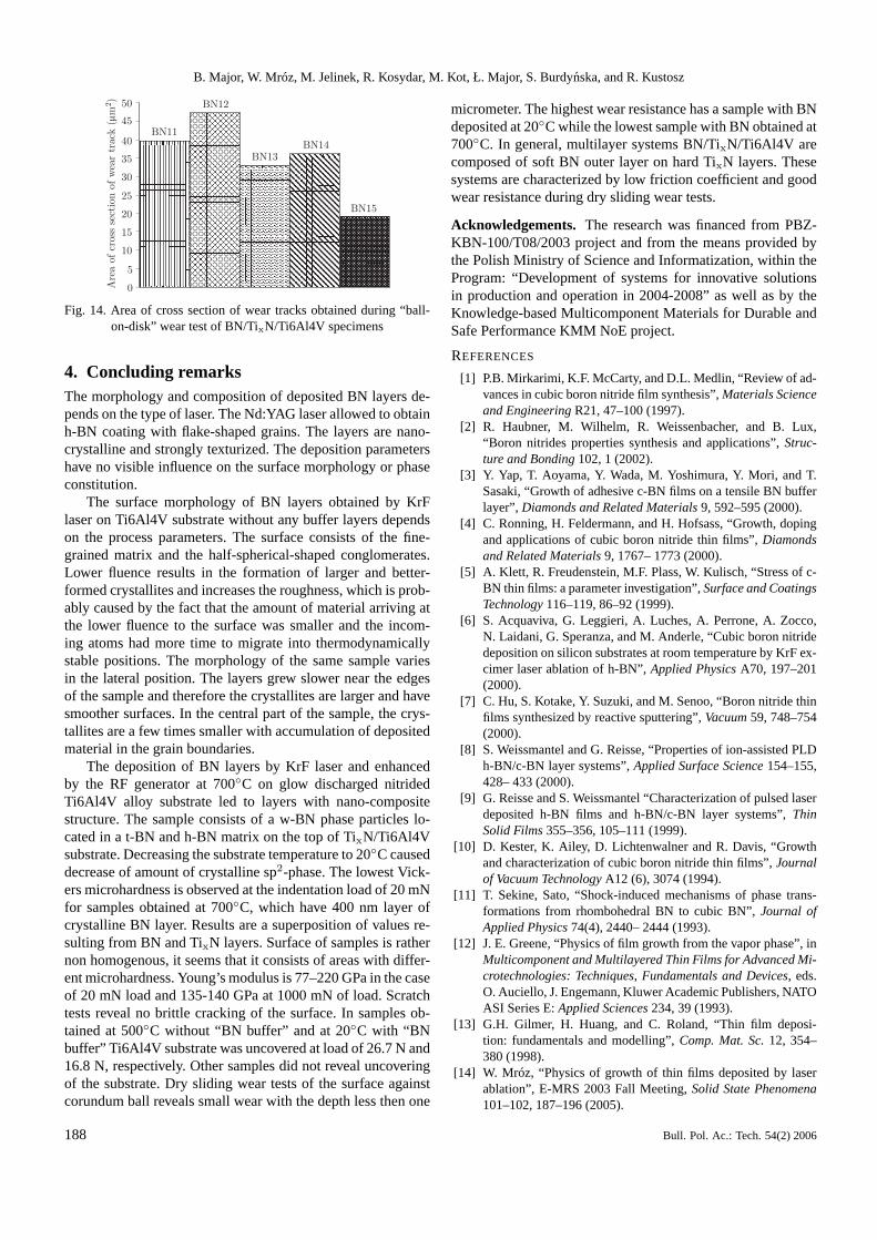
Dry sliding wear tests of samples against alumina ball werecarried out. During tests a friction coefficient was continuouslyrecorded. Dependence of a friction coefficient from numberof sliding cycles is presented in Fig. 12. The graph shows anevolution of friction coefficient. In all samples two stages areclearly visible. Step 1, up to 100–200 cycles, is attributed tomatching and smoothing of the sliding surfaces. Progressiveraise of friction coefficient up to f = 0.2–0.3 is observed. In thesecond step friction coefficient is reduced to a constant valuein samples BN13 (f = 0.2), BN14 (f = 0.18) and BN15 (f =0.16). The other samples, i.e. BN11 and BN12, reveal a pro-portional raise of friction coefficient to value of around 0.35.After 2000 cycles, at the end of the tests, the lowest frictioncoefficient is observed in BN15 (f = 0.16), while the highest inBN12 (f = 0.36) sample. It seems that applying of lower sub-strate temperature during BN deposition, which led to obtain-ing of thinner and less crystalline BN layer, allows to decreasethe friction coefficient. According to AFM examinations (Fig.6) the surface morphology and roughness of BN12 and BN15samples are different what may also influence the friction be-haviour. Cross-sectional profiles of wear tracks are presentedin Fig. 13, while their cross-sectional areas are shown in Fig.14. The largest wear depth is observed in samples BN11 andBN12, 890 and 940 nm, respectively. In these samples BNwas deposited at the highest temperature of 700◦C with thelargest thickness of the BN layer of around 400 nm and highdegree of crystalline sp2-BN. BN13 and BN14 samples havea wear depth around 600 nm, while BN15 is characterizedby the smallest value of 450 nm. In all cases, wear depth islarger than a thickness of BN layers deposited on the surfaceof TixN/Ti6Al4V specimens. Therefore BN layers must havebeen removed during sliding but they could also act as a lubri-cant layer forming a thin layer between the sample surface andthe corundum ball leading to decrease of measured friction co-efficient. A total cross-sectional area of wear track depends onthe temperature of BN deposition (Fig. 14). The largest areais in the case of BN12 and BN11, while the lowest in BN15sample. Wear depths and areas are very close in BN11 andBN12 as well as BN13 and BN14 what indicates that applyingof “buffer BN” does not influence the wear behaviour in thistest. In general, samples show good wear resistance and lowfriction coefficient. In this test BN15 exhibits the best wear re-sistance of all samples, what is contrary to the results of scratchtest. Differences may result from various material and geom-etry of scratch tip and wear ball. More tribological tests arebeing made.
Bull. Pol. Ac.: Tech. 54(2) 2006 187
B. Major, W. Mróz, M. Jelinek, R. Kosydar, M. Kot, Ł. Major, S. Burdynska, and R. Kustosz
Fig. 14. Area of cross section of wear tracks obtained during “ball-on-disk” wear test of BN/TixN/Ti6Al4V specimens
4. Concluding remarksThe morphology and composition of deposited BN layers de-pends on the type of laser. The Nd:YAG laser allowed to obtainh-BN coating with flake-shaped grains. The layers are nano-crystalline and strongly texturized. The deposition parametershave no visible influence on the surface morphology or phaseconstitution.
The surface morphology of BN layers obtained by KrFlaser on Ti6Al4V substrate without any buffer layers dependson the process parameters. The surface consists of the fine-grained matrix and the half-spherical-shaped conglomerates.Lower fluence results in the formation of larger and better-formed crystallites and increases the roughness, which is prob-ably caused by the fact that the amount of material arriving atthe lower fluence to the surface was smaller and the incom-ing atoms had more time to migrate into thermodynamicallystable positions. The morphology of the same sample variesin the lateral position. The layers grew slower near the edgesof the sample and therefore the crystallites are larger and havesmoother surfaces. In the central part of the sample, the crys-tallites are a few times smaller with accumulation of depositedmaterial in the grain boundaries.
The deposition of BN layers by KrF laser and enhancedby the RF generator at 700◦C on glow discharged nitridedTi6Al4V alloy substrate led to layers with nano-compositestructure. The sample consists of a w-BN phase particles lo-cated in a t-BN and h-BN matrix on the top of TixN/Ti6Al4Vsubstrate. Decreasing the substrate temperature to 20◦C causeddecrease of amount of crystalline sp2-phase. The lowest Vick-ers microhardness is observed at the indentation load of 20 mNfor samples obtained at 700◦C, which have 400 nm layer ofcrystalline BN layer. Results are a superposition of values re-sulting from BN and TixN layers. Surface of samples is rathernon homogenous, it seems that it consists of areas with differ-ent microhardness. Young’s modulus is 77–220 GPa in the caseof 20 mN load and 135-140 GPa at 1000 mN of load. Scratchtests reveal no brittle cracking of the surface. In samples ob-tained at 500◦C without “BN buffer” and at 20◦C with “BNbuffer” Ti6Al4V substrate was uncovered at load of 26.7 N and16.8 N, respectively. Other samples did not reveal uncoveringof the substrate. Dry sliding wear tests of the surface againstcorundum ball reveals small wear with the depth less then one
micrometer. The highest wear resistance has a sample with BNdeposited at 20◦C while the lowest sample with BN obtained at700◦C. In general, multilayer systems BN/TixN/Ti6Al4V arecomposed of soft BN outer layer on hard TixN layers. Thesesystems are characterized by low friction coefficient and goodwear resistance during dry sliding wear tests.
Acknowledgements. The research was financed from PBZ-KBN-100/T08/2003 project and from the means provided bythe Polish Ministry of Science and Informatization, within theProgram: “Development of systems for innovative solutionsin production and operation in 2004-2008” as well as by theKnowledge-based Multicomponent Materials for Durable andSafe Performance KMM NoE project.
REFERENCES
[1] P.B. Mirkarimi, K.F. McCarty, and D.L. Medlin, “Review of ad-vances in cubic boron nitride film synthesis”,Materials Scienceand EngineeringR21, 47–100 (1997).
[2] R. Haubner, M. Wilhelm, R. Weissenbacher, and B. Lux,“Boron nitrides properties synthesis and applications”,Struc-ture and Bonding102, 1 (2002).
[3] Y. Yap, T. Aoyama, Y. Wada, M. Yoshimura, Y. Mori, and T.Sasaki, “Growth of adhesive c-BN films on a tensile BN bufferlayer”, Diamonds and Related Materials9, 592–595 (2000).
[4] C. Ronning, H. Feldermann, and H. Hofsass, “Growth, dopingand applications of cubic boron nitride thin films”,Diamondsand Related Materials9, 1767– 1773 (2000).
[5] A. Klett, R. Freudenstein, M.F. Plass, W. Kulisch, “Stress of c-BN thin films: a parameter investigation”,Surface and CoatingsTechnology116–119, 86–92 (1999).
[6] S. Acquaviva, G. Leggieri, A. Luches, A. Perrone, A. Zocco,N. Laidani, G. Speranza, and M. Anderle, “Cubic boron nitridedeposition on silicon substrates at room temperature by KrF ex-cimer laser ablation of h-BN”,Applied PhysicsA70, 197–201(2000).
[7] C. Hu, S. Kotake, Y. Suzuki, and M. Senoo, “Boron nitride thinfilms synthesized by reactive sputtering”,Vacuum59, 748–754(2000).
[8] S. Weissmantel and G. Reisse, “Properties of ion-assisted PLDh-BN/c-BN layer systems”,Applied Surface Science154–155,428– 433 (2000).
[9] G. Reisse and S. Weissmantel “Characterization of pulsed laserdeposited h-BN films and h-BN/c-BN layer systems”,ThinSolid Films355–356, 105–111 (1999).
[10] D. Kester, K. Ailey, D. Lichtenwalner and R. Davis, “Growthand characterization of cubic boron nitride thin films”,Journalof Vacuum TechnologyA12 (6), 3074 (1994).
[11] T. Sekine, Sato, “Shock-induced mechanisms of phase trans-formations from rhombohedral BN to cubic BN”,Journal ofApplied Physics74(4), 2440– 2444 (1993).
[12] J. E. Greene, “Physics of film growth from the vapor phase”, inMulticomponent and Multilayered Thin Films for Advanced Mi-crotechnologies: Techniques, Fundamentals and Devices, eds.O. Auciello, J. Engemann, Kluwer Academic Publishers, NATOASI Series E:Applied Sciences234, 39 (1993).
[13] G.H. Gilmer, H. Huang, and C. Roland, “Thin film deposi-tion: fundamentals and modelling”,Comp. Mat. Sc.12, 354–380 (1998).
[14] W. Mróz, “Physics of growth of thin films deposited by laserablation”, E-MRS 2003 Fall Meeting,Solid State Phenomena101–102, 187–196 (2005).


![Pulsed Laser Deposition of YSZ and Al2O3 Thin Films: Part 1 ......thin films [16-26]. Pulsed laser deposition has also been used for the development of nano-structured thin films [27,](https://static.documents.pub/doc/80x56/60f688b3c8026a3be761a2f6/pulsed-laser-deposition-of-ysz-and-al2o3-thin-films-part-1-thin-films-16-26.jpg)


