Page 1
1
Board level diagnosis techniques using VHDL modeling
Timothy Wayne Crockett
Thesis submitted to the Faculty of the Virginia Polytechnic
Institute and State University in partial fulfillment of the
requirements for the degree of
Master of Science
in
Electrical Engineering
Dr. J. R.. Armstrong, Chairman
Dr. F. G. Gray
Dr W. R. Cyre
December 10, 1998
Blacksburg, Virginia
Keywords: Diagnosis, VHDL, Java, IEEE WAVES, Troubleshooting
Copyright 1998, Timothy W. Crockett
Page 2
ii
Board level diagnosis techniques using VHDL modeling
Timothy Wayne Crockett
(ABSTRACT)
This thesis presents a program developed to implement techniques for troubleshooting digital
boards. There are old boards still in service that have no built in testing circuits. This makes
troubleshooting them time consuming and difficult. In making this program two questions were posed;
“How would a technician normally perform this operation?” and “How can a program help him/her do this
better?” Having experience as a technician himself, the author could easily answer the first question. The
experienced technician would put a known sequence of inputs into the board and compare the actual
outputs to the expected. Any outputs that did not compare would lead the technician to the section of board
most closely related to the fault. Within this new section, new signals are probed while the same patterns
of inputs are repeated. This technique is commonly referred to as bracketing. Bracketing involves these
four steps:
1. Select where to probe.
2. Run test inputs and sample.
3. Use sampled information to reduce the suspect set.
4. If the suspect set is not a single component then repeat steps 1 through 4.
The answer to the second question has no easy answer. That is where it is hoped this program can
help. The program uses information from a non-faulted VHDL model of the board to learn what to expect.
Since there is no interface to a real probed board, VHDL is also used to model the faulted board.
Page 3
iii
Acknowledgements
I would like to thank the following professors:
Dr. Armstrong for giving me this opportunity to complete my masters. Without
his encouragement and support I doubt I would have ever tried.
Dr. Gray for his advice and support as well as his valuable bicycle safety tips.
Without which, I may have never lived to see a Masters degree.
Dr. Ha for allowing me to bounce my ideas off of him.
Dr. Cyre for his support and assistance.
Dr. Nunnaly for being there and listening.
I dedicate this work to my parents who encouraged, fed and clothed me while I tried to
live on a student's income.
Page 4
iv
Table of Contents
Chapter 1 Introduction ................................................................................................................1
1.1 MOTIVATION ......................................................................................................................1
1.2 CONTRIBUTIONS.................................................................................................................1
Chapter 2 Approach....................................................................................................................3
Chapter 3 Implementation...........................................................................................................5
3.1 OVERVIEW.........................................................................................................................5
3.2 READING STRUCTURAL INFORMATION FROM THE VHDL FILE. .............................................6
3.3 REDUCING THE SET OF SUSPECT COMPONENTS.....................................................................8
3.3.1. Reducing the suspect space in a non-feedback circuit.................................................8
3.3.2. Reducing the suspect space in a feedback circuit........................................................9
3.4 SELECTING SIGNALS ON THE BOARD TO PROBE...................................................................11
3.4.1. Leveling the suspect graph .......................................................................................12
3.4.2. Probe point selection methods..................................................................................14
3.4.2.1.Binary Selection ..................................................................................................14
3.4.2.2.Forward Selection................................................................................................14
3.4.2.3.Backward Selection .............................................................................................14
3.4.2.4.Random Selection................................................................................................15
Chapter 4 Software Description ................................................................................................19
4.1 OVERVIEW.......................................................................................................................19
4.1.1. The VHDL parser.....................................................................................................20
4.1.2. Board Level Diagnosis.............................................................................................22
4.1.2.1. Binary mode .......................................................................................................22
4.1.2.2. Forward mode ....................................................................................................31
4.1.2.3. Backward mode..................................................................................................31
4.1.2.4. Random mode ....................................................................................................31
Chapter 5 Results......................................................................................................................32
5.1 OVERVIEW.......................................................................................................................32
5.2 BINARY MODE, ARRAY MULTIPLIER WITH I_21 FAULT ......................................................32
5.2.1. Step 1.......................................................................................................................32
5.2.2. Step 2.......................................................................................................................36
Page 5
v
5.2.3. Step 3.......................................................................................................................39
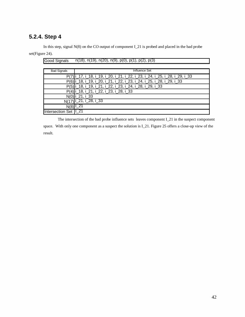
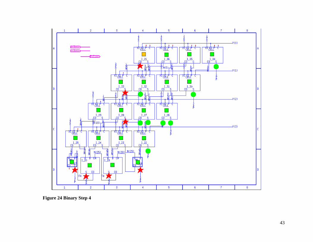
5.2.4. Step 4.......................................................................................................................42
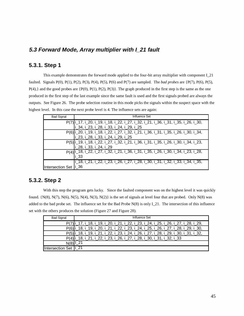
5.3 FORWARD MODE, ARRAY MULTIPLIER WITH I_21 FAULT...................................................45
5.3.1. Step 1.......................................................................................................................45
5.3.2. Step 2.......................................................................................................................45
5.4 RANDOM MODE, ARRAY MULTIPLIER WITH I_21 FAULT ....................................................49
5.4.1. Step 1.......................................................................................................................49
5.4.2. Step 2.......................................................................................................................49
5.4.3. Step 3.......................................................................................................................49
5.5 BINARY WITH LOOP DETECTION, IIR FILTER WITH I_3 FAULTED.........................................55
5.5.1. Step 1.......................................................................................................................55
5.5.2. Step 2.......................................................................................................................58
5.6 BINARY WITH LOOP DETECTION, IIR FILTER WITH I_1 FAULTED.........................................60
5.6.1 Step 1........................................................................................................................60
5.6.2 Step 2........................................................................................................................60
5.6.3 Step 3........................................................................................................................61
5.6.4. Step 4.......................................................................................................................62
5.7 BINARY MODE, BUSSER WITH I_6 FAULTED......................................................................70
5.7.1 Step 1........................................................................................................................70
5.7.2 Step 2........................................................................................................................70
5.7.3 Step 3........................................................................................................................70
5.8 TABLES OF RESULTS.........................................................................................................74
5.8.1 MPU2 results.........................................................................................................74
5.8.2 4 bit Array multiplier results..................................................................................74
5.8.3 UART results .........................................................................................................75
5.8.4 IIR Filter results ....................................................................................................75
5.8.5 Busser results ........................................................................................................75
Chapter 6 Conclusions ..............................................................................................................82
Chapter 7 Proposed Future Work ..............................................................................................82
7.1 TECHNICIAN INTERFACE FOR REAL WORLD USE.................................................................82
7.2 EDIF FILE PARSER............................................................................................................82
Page 6
vi
7.3 IMPLEMENT MERYEM MARZOUKI’ S FUZZY QUALITATIVE PROBE POINT SELECTION
ALGORITHM[4] .......................................................................................................................83
References ................................................................................................................................84
Appendix A. Users Guide .........................................................................................................86
1. PROGRAM OVERVIEW.........................................................................................................86
1.1 Features.......................................................................................................................86
A. Supported search modes .............................................................................................86
B. Written in Java............................................................................................................87
C. Command line interface..............................................................................................88
2. INSTALLATION ...................................................................................................................88
2.1 Java.............................................................................................................................88
2.2 BLD.............................................................................................................................88
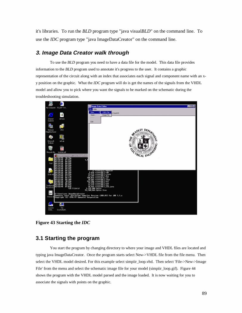
3. IMAGE DATA CREATOR WALK THROUGH.............................................................................89
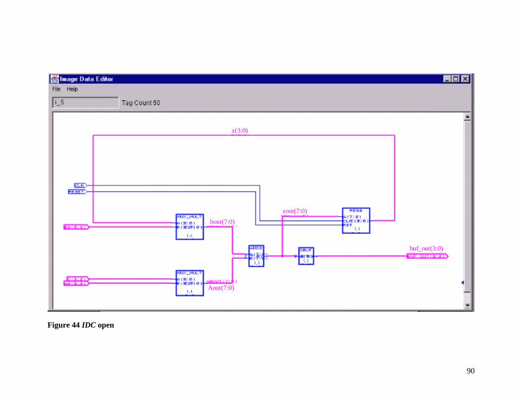
3.1 Starting the program....................................................................................................89
3.2 Placing points on the graphic ......................................................................................91
4. BOARD LEVEL DIAGNOSTIC WALK THROUGH......................................................................93
4.1 Starting the program....................................................................................................93
4.2 Stepping through the simulation...................................................................................95
5. CREATING TABLE FILES FROM MODEL SIMULATIONS............................................................97
Appendix B. VHDL Models.....................................................................................................99
1. SIMPLE IIR FILTER .............................................................................................................99
1.1 Model ..........................................................................................................................99
1. Simpiir_loop file .........................................................................................................99
2. ADDER .................................................................................................................... 103
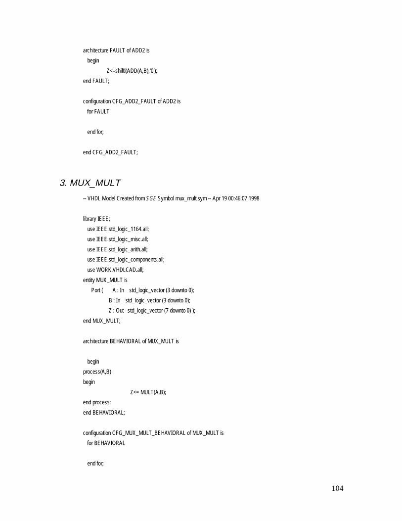
3. MUX_MULT............................................................................................................ 104
4. OBUF ....................................................................................................................... 105
1.2 Test bench.................................................................................................................. 106
1. Header ......................................................................................................................106
2. UUT_TEST_PINS .................................................................................................... 107
3. WAVE Pattern Generator.......................................................................................... 107
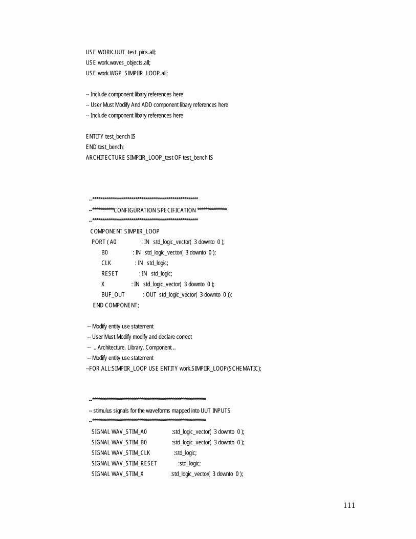
4. Test Bench file .......................................................................................................... 110
Page 7
vii
1.3 Test Pattern ...............................................................................................................115
1.4 Schematic ..................................................................................................................118
2. ARRAY MULTIPLIER ......................................................................................................... 118
2.1 Model ........................................................................................................................ 118
1. Multiplier file ............................................................................................................ 118
2. CELL........................................................................................................................122
3. FA file....................................................................................................................... 125
4. HA file ...................................................................................................................... 126
2.2 Test Bench .................................................................................................................127
1. Header ......................................................................................................................127
2. UUT_TEST_PINS .................................................................................................... 128
3. WAVE Pattern Generator.......................................................................................... 129
4. Test Bench file .......................................................................................................... 131
2.3 Test Pattern ...............................................................................................................135
2.4 Schematic ..................................................................................................................136
3. MPU2.............................................................................................................................. 136
3.1 Model ........................................................................................................................ 136
1. MPU2 ....................................................................................................................... 136
2. CLKSTB................................................................................................................... 143
3. MUXP1..................................................................................................................... 144
4. CRT .......................................................................................................................... 146
5. MUXP ...................................................................................................................... 148
6. ALU.......................................................................................................................... 150
7. REG.......................................................................................................................... 152
8. BUF .......................................................................................................................... 154
3.2 Test Bench .................................................................................................................155
1. Header ......................................................................................................................155
2. UUT_TEST_PINS .................................................................................................... 156
3. WAVE Pattern Generator.......................................................................................... 156
4. Test Bench file .......................................................................................................... 159
3.3 Test Pattern ...............................................................................................................164
Page 8
viii
3.4 Schematic ..................................................................................................................171
4. UART ............................................................................................................................. 171
4.1 Model ........................................................................................................................ 171
1. UART ....................................................................................................................... 175
2. IN_CON ................................................................................................................... 180
3. CNT_DNZ1 .............................................................................................................. 182
4. SHIFT_IN................................................................................................................. 184
5. BUFF........................................................................................................................185
6. CNT_DNZ................................................................................................................ 187
7. SHIFT_REG ............................................................................................................. 188
8. RS_EDGE................................................................................................................. 189
4.2 Test Bench .................................................................................................................190
1. Header ......................................................................................................................190
2 UUT_TEST_PINS ..................................................................................................... 191
3. WAVE Pattern Generator.......................................................................................... 191
4. Test Bench file .......................................................................................................... 195
4.3 Test Pattern ...............................................................................................................200
4.4 Schematic ..................................................................................................................201
4. BUSSER............................................................................................................................ 202
4.1 Model ........................................................................................................................ 202
1. BUSSER................................................................................................................... 202
2. BUSMOD ................................................................................................................. 204
3. TRIBUF.................................................................................................................... 205
4.2 Test Bench .................................................................................................................206
4.3 Schematic ..................................................................................................................208
Appendix C. VISC Packages................................................................................................... 209
1. EDU.VT.VISC.UTIL ............................................................................................................. 209
1.1 Interfaces Index ......................................................................................................... 209
1. edu.vt.visc.util.node .................................................................................................. 209
2. PACKAGE EDU.VT.VISC.VHDL ............................................................................................ 234
2.1 Class Index ................................................................................................................234
Page 9
ix
1. edu.vt.visc.vhdl.architecture ...................................................................................... 234
2. edu.vt.visc.vhdl.bit .................................................................................................... 236
3. edu.vt.visc.vhdl.bitvector .......................................................................................... 243
4. edu.vt.visc.vhdl.component ....................................................................................... 252
5. edu.vt.visc.vhdl.configuration.................................................................................... 253
6. edu.vt.visc.vhdl.entity................................................................................................ 255
7. edu.vt.visc.vhdl.port .................................................................................................. 258
8. edu.vt.visc.vhdl.vhdl.................................................................................................. 259
2.2 Exception Index......................................................................................................... 264
1. edu.vt.visc.vhdl.vhdlException.................................................................................. 264
3. PACKAGE EDU.VT.VISC.BLT ............................................................................................... 265
3.1 Class Index ................................................................................................................265
1. edu.vt.visc.blt.Record................................................................................................ 265
2. edu.vt.visc.blt.backwardBLT..................................................................................... 267
3. edu.vt.visc.blt.binaryBLT.......................................................................................... 268
4. edu.vt.visc.blt.binary_w_feedback............................................................................. 275
5. edu.vt.visc.blt.forwardBLT........................................................................................ 277
6. edu.vt.visc.blt.randomBLT........................................................................................ 278
3.2 Exception Index......................................................................................................... 279
1. edu.vt.visc.blt.bltException ....................................................................................... 279
Vita......................................................................................................................................... 283
List of Figures
Figure 1 Diagnosis Flow diagram.................................................................................... 3
Figure 2 Board Level Diagnosis Tool Implementation .................................................... 6
Figure 3 Feedback example 1.......................................................................................... 9
Figure 4 Feedback example 2........................................................................................ 10
Figure 5 Probe example 1 ............................................................................................. 11
Figure 6 Probe example 2 ............................................................................................. 12
Figure 7 Network examples .......................................................................................... 13
Page 10
x
Figure 8 Suspect reduction with space intersection........................................................ 16
Figure 9 Simple IIR Schematic ..................................................................................... 17
Figure 10 Graph representation of Simple IIR filter model............................................ 18
Figure 11 VHDL sections for parsing............................................................................ 19
Figure 12 BLD high level flow diagram........................................................................ 21
Figure 13 Propagation Cone for P2................................................................................ 24
Figure 14 Propagation cone for P3................................................................................. 25
Figure 15 Intersection of P2 and P3................................................................................ 26
Figure 16 Limiting space by probing............................................................................. 27
Figure 17 Levelizing ..................................................................................................... 30
Figure 18 Binary Step 1 ................................................................................................ 34
Figure 19 Binary Step 1 Close up.................................................................................. 35
Figure 20 Binary Step 2 ................................................................................................ 37
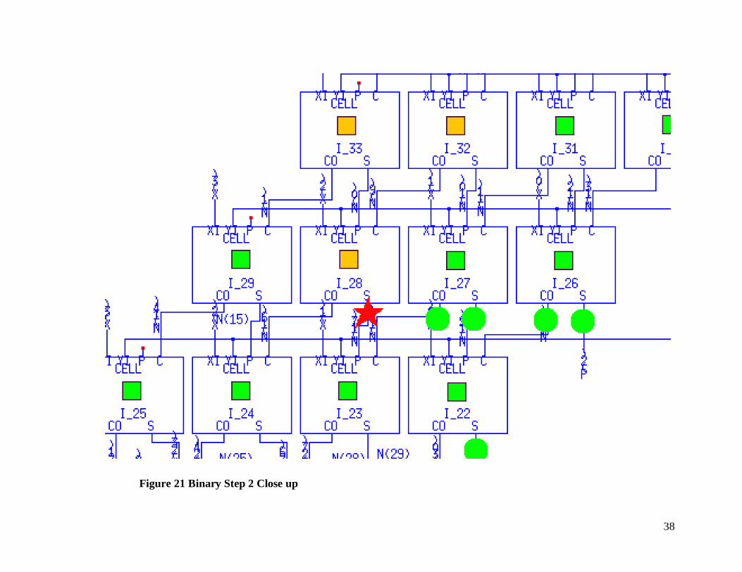
Figure 21 Binary Step 2 Close up.................................................................................. 38
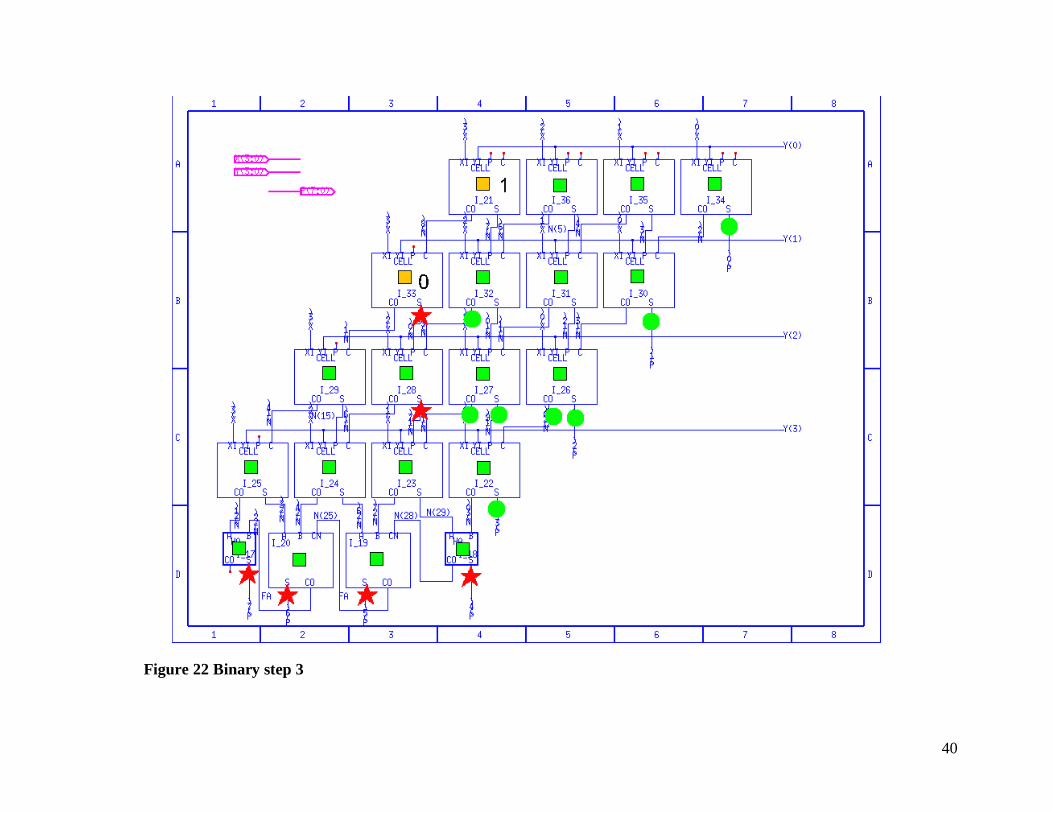
Figure 22 Binary step 3................................................................................................. 40
Figure 23 Binary Step 3 close-up .................................................................................. 41
Figure 24 Binary Step 4 ................................................................................................ 43
Figure 25 Binary Step 4 close-up .................................................................................. 44
Figure 26 forward Step 1 .............................................................................................. 46
Figure 27 forward Step 2 .............................................................................................. 47
Figure 28 forward Step 2 close up................................................................................. 48
Figure 29 random Step 2............................................................................................... 51
Figure 30 random Step 2 closeup .................................................................................. 52
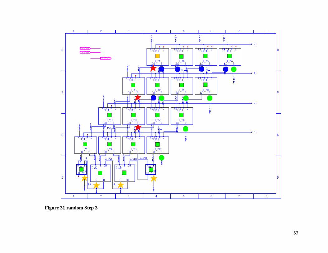
Figure 31 random Step 3............................................................................................... 53
Figure 32 random Step 3 close up ................................................................................. 54
Figure 33 Binary w/ loop detection Step 1 .................................................................... 57
Figure 34 Binary w/ loop detection Step 2 .................................................................... 59
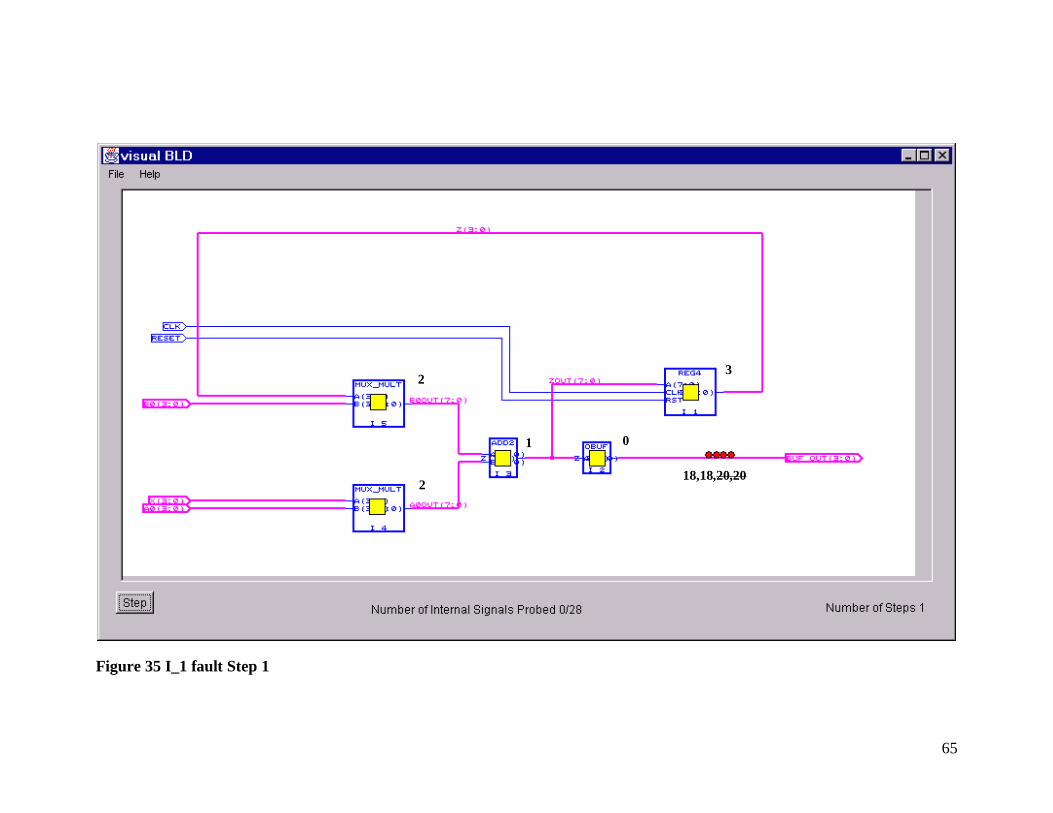
Figure 35 I_1 fault Step 1 ............................................................................................. 65
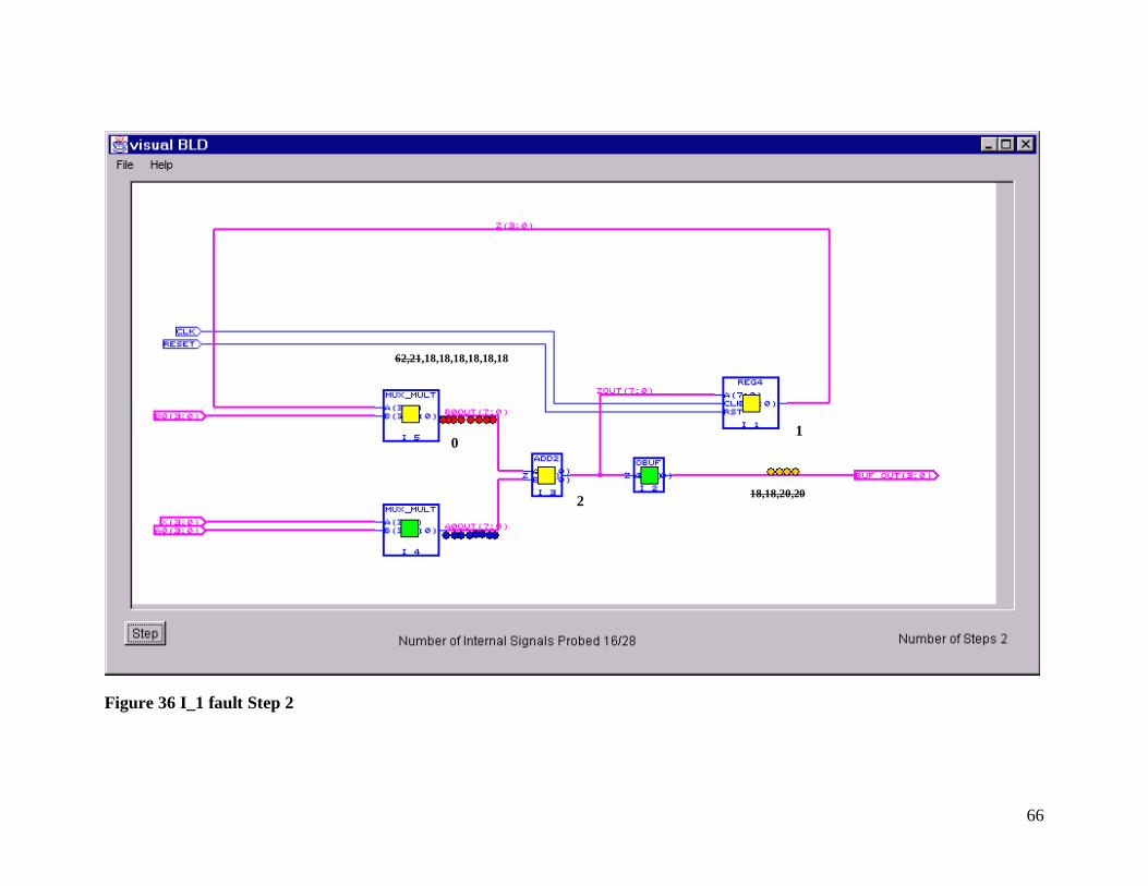
Figure 36 I_1 fault Step 2 ............................................................................................. 66
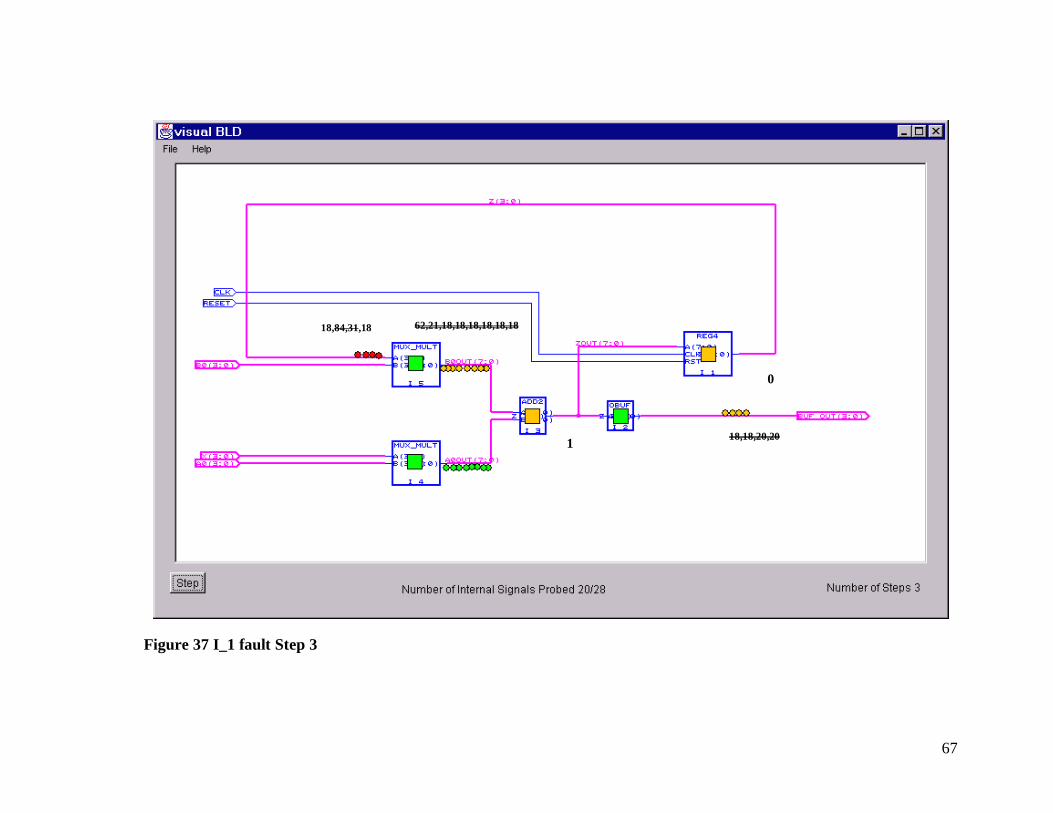
Figure 37 I_1 fault Step 3 ............................................................................................. 67
Figure 38 I_1 fault step 4a ............................................................................................ 68
Page 11
xi
Figure 39 I_1 fault Step 4b............................................................................................ 69
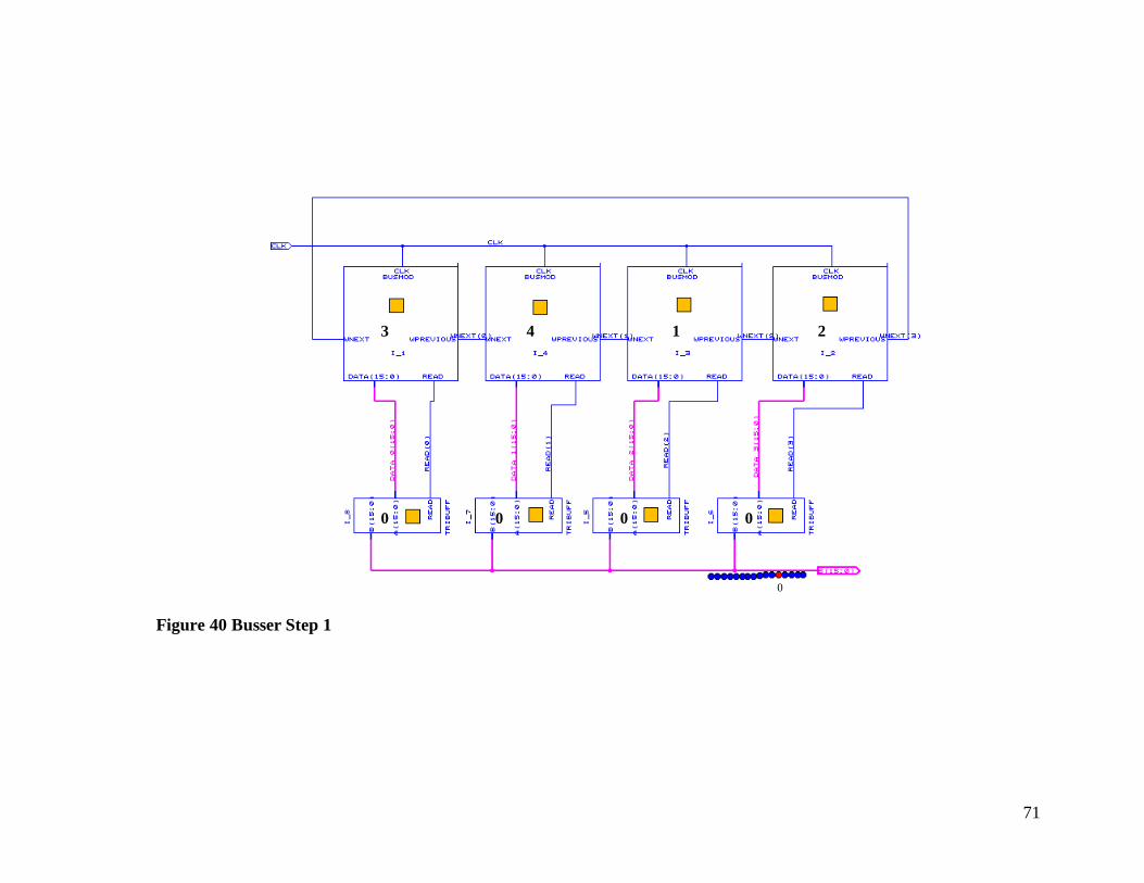
Figure 40 Busser Step 1 ................................................................................................ 71
Figure 41 Busser Step 2 ................................................................................................ 72
Figure 42 Busser Step 3 ................................................................................................ 73
Figure 43 Starting the IDC ............................................................................................ 89
Figure 44 IDC open ...................................................................................................... 90
Figure 45 Marking complete ......................................................................................... 92
Figure 46 Opening dialogue boxes ................................................................................ 94
Figure 47 Source dialogue............................................................................................. 94
Figure 48 Ready to start the search................................................................................ 96
Figure 49 Search complete............................................................................................ 97
Figure 50 Simple IIR Schematic ................................................................................. 118
Figure 51 Array Multiplier Schematic......................................................................... 136
Figure 52 MPU2 Schematic ........................................................................................ 171
Figure 53 UART Schematic ........................................................................................ 201
Figure 54 BUSSER Schematic.................................................................................... 208
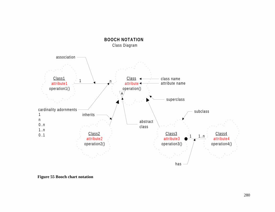
Figure 55 Booch chart notation ................................................................................... 280
Figure 56 Class Diagram of parser #1 ......................................................................... 281
Figure 57 Class Diagram of parser #2 ......................................................................... 282
List of terms
Bad Probe A signal who’s actual value doesn’t match it’s expected value.BLD - Board Level Diagnosis programBLT - Board Level Test packageInput Bridge Signal A signal that is either directed from the non-suspect set to the
suspect set or is a signal input directed into the suspect set.Output Bridge Signal-
A signal that is either directed from the suspect set to the non-suspect area or is a circuit output directed from the suspect set.
Fault coverage- Is the ratio of the number of faults that a test pattern detects to thenumber of possible faults in the circuit.
Good Probe A signal who’s actual value matches it’s expected value.IDC - Image Data Creator programInfluence Set - The set of all components that can possibly contribute to the state of
a signal. Can also be thought of the input cone to a signal.Single stuck at faultcondition
A circuit fault condition in which only one signal in the circuit isstuck in the ‘1’ or ‘0’ state.
Suspect area/space Set of vertices in the circuit graph suspected of being faulted. The
Page 12
xii
sub-graph formed by this set is always connected[3].Levelizing - Partitioning the signals and components of a graph according to their
distance from the output bridge signals.SGE Synopsys Graphical Environment program
Page 13
1
Chapter 1 Introduction
1.1 Motivation
There are still boards in service that have no built in self-testing. When these boards fail they are
often difficult and costly to troubleshoot. By developing a program that could suggest what signals would
give the most information about the problem it is possible to make the troubleshooting process more
efficient and less time consuming for the technician. Using VHDL modeling techniques it is possible to
predict the circuits correct behavior when a sequence of test patterns are applied. This along with the
circuit connection information is used to develop a troubleshooting simulation that demonstrates the
effectiveness of different probing strategies on a faulted board. No real board is actually probed. VHDL is
used to simulate the behavior of a faulted board for probing. The program developed for this project uses
only the structural information from the VHDL model and the signal values from faulted and non-faulted
VHDL simulation runs to demonstrate different probing strategies on a faulted circuit board.
To simplify the problems that the Board Level Diagnosis Program must deal with some
assumptions were made. First is the single fault assumption. This is a common assumption made in test
generation. In this case it assumes that there is only one faulted component on the board. This is a
reasonable assumption since, in the author’s experience, most multiple faults are related. In cases where a
second component is damaged due to a first, the program should discover both. This is due to the
program's use of component dependencies in its space reduction algorithm. The second assumption is that
the same test patterns are applied in the same sequence each time a new set of signals is sampled. This
supports the causal relationship between each set of selected sampled signals. When new internal signals
are chosen from within a suspect space, it is assumed that the non-matching samples on the signals closest
to the output are related to the internal signals by a cone of influence. If the same test patterns are not
applied in the same sequence there is no guarantee for the existence of this relationship. This can introduce
errors into the suspect space reduction and feedback handling algorithms. Last is the assumption that there
is some sequential element in any and all loops. When a pattern is applied the circuit is allowed to settle
before it is sampled. A feedback loop that does not have a sequential element in it may never settle and
make troubleshooting nearly impossible. This requirement is met by most good designs.
1.2 Contributions
1. A Board Level Diagnosis program that provides a graphical tool for observing the
effectiveness of probing strategies and space reduction techniques as they are applied to a
faulted board.
Page 14
2
2. An Image Data Creator program that builds data files for combining graphical and
positional information needed by the BLD.
3. The edu.vt.visc.blt package provides a set of classes and methods for working with board
diagnosis problems.
4. The edu.vt.visc.vhdl package provides a set of classes and methods for parsing, storing
and retrieving information from a VHDL file.
5. The edu.vt.visc.util package provides a collection of generic data structures and tools
such as sets, queues and hierarchical hash tables.
Since no tools were available, new tools were created to meet the goals of the project. All of these
programming tools were written in JAVA and are available from one of three packages. The first tool was
the VHDL parser. This is a JAVA class that reads a VHDL file and provides an interface for acquiring
circuit model information. The second tool is the Board Level Tester. This is a group of classes gathered
into the edu.vt.visc.blt package. These tools use the abilities provided by the edu.vt.visc.vhdl package to
gather and manipulate information about the circuit. Some of the more significant tools available in the
edu.vt.visc.blt package are the space reduction and levelizing algorithms. The core of the Board Level
Diagnosis program is the space reduction algorithm. This algorithm takes the probe sample information and
reduces the circuit to a minimum number of suspect components.
The most apparent and least important result of this research is the Board Level Diagnosis (BLD)
program. Using the tools provided by the edu.vt.visc.blt package, the BLD program provides a graphical
user interface. Most of the BLD is concerned with setting up the edu.vt.visc.blt tools and handling user
interaction. This is a good example of program abstraction that takes advantage of Java's object oriented
capabilities. As simple as it is, the BLD program provides an excellent tool for evaluating different probe
strategies. The real result of this thesis is the development of a core set of data structures and tools for
handling the diagnosis problem. These tools handle details like circuit storage, suspect component
reduction and circuit graph manipulation. Using these tools a programmer can work at a higher level of
abstraction, leaving the Board Level Troubleshooting tools provided by the edu.vt.visc.blt package to
handle the details.
Page 15
3
Chapter 2 Approach
SynopsisSimulator
SimulationRecord
TroubleShooter
UUT
Probe Result
TestVectors
VHDL
Figure 1 Diagnosis Flow diagram
Figure 1 shows the flow diagram of the diagnosis procedure. The first part is the generation of a
non-faulted VHDL model representing the Unit Under Test(UUT). A set of test vectors for the UUT are
used to drive the VHDL model during simulation and a record of the simulation signal activity is created.
The troubleshooter program uses a VHDL structural model of the UUT to build a graph representation and
a signal name reference table. Using this information the Troubleshooter guides the probes on the UUT
and evaluates the samples. With each probe sample cycle the Troubleshooter learns more about the UUT's
problem. The Troubleshooters goal is to isolate the possible faulty component on the UUT with a minimum
Page 16
4
of information. In the BLD program, a simulation record of a faulted model simulates the UUT. For
specific information on the simulation record see the User manual in appendix A.
The board level trouble-shooting problem can be broken down into three main tasks.
1. Read the structural information from the VHDL file
2. Reduce the set of suspect components.
3. Select what signals on the board to probe.
The first task consists of parsing a structural VHDL file created using the Synopsys Graphical
Environment (SGE) design tools. The parsing operation will generate a computer usable graph to represent
the structural relationships between the components and the signals. The goal of the program is to find the
faulted component with as few signals probed as possible. Fewer probe samples means a shorter time spent
troubleshooting the board. Once placed, the probes sample the operation of the board under a fixed set of
test patterns. The troubleshooting procedure starts with all components in the set of suspects. The
combination of the signals that tested bad and those that tested good are used to reduce the suspect set until
it only contains a single component. This assumes that there is only a single fault on the board. There are
three possible results from the diagnosis procedure. The first is that the routine ends with only one
component in the suspect set. This is the desired situation. The second is when the routine ends with more
than one suspect component. This happens when there are more than two faults on the board or the
circuit’s layout prevents resolution to a single component. Loops and or busses in the circuit are examples
of this. If caused by two separate faults then the components in the suspect set are not necessarily the
culprits in this case. The third is that the routine ends with an empty set. This happens when either there
are no faults on the board or the fault is undetectable. Tasks 2 and 3 are repeated until there is a solution or
there are no more signals to probe.
Page 17
5
Chapter 3 Implementation
3.1 Overview
Figure 2 shows the block diagram of the board level diagnosis tool implementation. The process
begins when the user creates a schematic of the board using SGE. The user then annotates the schematic
with required labels using the Image Data Creator(IDC). The structural VHDL model, representing the
schematic is processed by the Parser to produce the circuit graph. The Board Level Tester (BLT) tools,
under control of BLD, uses the circuit graph and good and faulty board simulation files to perform the
diagnosis. The BLD is the user interface that controls the diagnosis process. The system is implemented in
JAVA and utilizes these three packages from a package library:
1) The edu.vt.visc.blt package provides a set of classes and methods for working with board
diagnosis problems.
2) The edu.vt.visc.vhdl package provides a set of classes and methods for parsing, storing and
retrieving information from a VHDL file
3) The edu.vt.visc.util package provides a collection of generic data structures and tools such as sets,
queues and hierarchical hash tables.
Page 18
6
SimulationFiles
SimulationFiles
BLT
PARSER
BLD
IDC
SGE
User:Control
&ObserveResults
User:Annotate
Schematic
User:Enter
Schematic
AnnotatedSchematic
Schematic
VHDL StructuralModel
CircuitGraph
Package LibraryBLT
VHDLUTILITY
Figure 2 Board Level Diagnosis Tool Implementation
3.2 Reading structural information from the VHDL file.
The first task is to build a directed graph from the structural VHDL description of the model. The
VHDL model is created using SGE. Each component is represented by a symbol that is wired into the
model. Every symbol has a VHDL entity architecture pair associated with it that describes the functionality
of the component for the simulator. While the Diagnosis program does not use the component's functional
information, the VHDL simulator does use it to create the simulation tables. For each board, multiple
models are made for use in the diagnosis program. The first model is non-faulted, and the rest represent
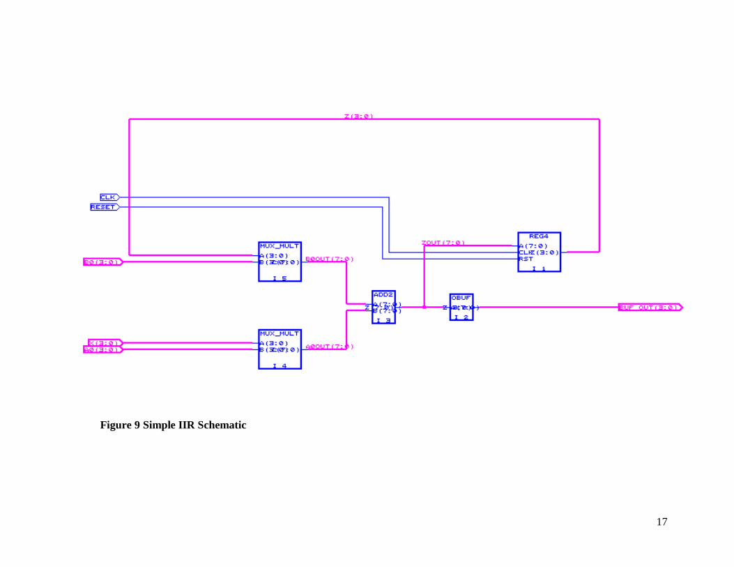
various possible board faults. Figure 9 shows the schematic for a second order filter called the simple IIR
model. Each component in the model is represented by a VHDL entity with multiple architectures. The
first architecture section represents a non-faulted model with each additional architecture section
representing the possible fault conditions. For convenience, each architecture section is assigned a
Page 19
7
configuration declaration. Here is an example of a component description for the OBUF component used
in the simple IIR model.
In the board level model the models are set up for simulation by using the late component binding
features of VHDL. This example shows how the OBUF fault is inserted into the simple IIR model's
configuration.
configuration CFG_SIMPIIR_LOOP_I2_FAULTED of SIMPIIR_LOOP is
for SCHEMATIC
for I_1: REG4
use configuration WORK.CFG_REG4_BEHAVIORAL;
end for;
for I_2: OBUF
use configuration WORK.CFG_OBUF_FAULT;
end for;
-- VHDL Model Created from SGE Symbol obuf.sym -- Apr 19 00:54:18 1998library IEEE; use IEEE.std_logic_1164.all; use IEEE.std_logic_misc.all; use IEEE.std_logic_arith.all; use IEEE.std_logic_components.all; use WORK.VHDLCAD.all;
entity OBUF is Port ( A : In std_logic_vector (7 downto 0); Z : Out std_logic_vector (3 downto 0) );end OBUF;
architecture BEHAVIORAL of OBUF isbegin
Z<=A(5 downto 2);end BEHAVIORAL;
configuration CFG_OBUF_BEHAVIORAL of OBUF is for BEHAVIORAL end for;end CFG_OBUF_BEHAVIORAL;
architecture FAULT of OBUF is
beginZ(3)<=A(2);Z(2)<=A(3);Z(1)<=A(4);Z(0)<=A(5);
end FAULT;
configuration CFG_OBUF_FAULT of OBUF is for FAULT end for;end CFG_OBUF_FAULT;
Non-faulted model
Faulted model
Non-faultedConfiguration
Faulted Configuration
OBUF fault
Page 20
8
for I_3: ADD2
use configuration WORK.CFG_ADD2_BEHAVIORAL;
end for;
for I_4, I_5: MUX_MULT
use configuration WORK.CFG_MUX_MULT_BEHAVIORAL;
end for;
end for;
In the test bench a number of configurations are set up. The first uses the non-faulted
configuration from the board model and the rest represent various possible single stuck at fault conditions.
When the test bench is simulated the desired fault model is called by its configuration name.
The circuit’s components and signals are both represented as vertices in the graph. The
connection relationships between the signals and components are represented as edges. Since information
about the components and signals are stored in the graph, they both must be vertices. An example of this
can be seen in Figure 10 where the simple IIR schematic is represented. The square symbols represent
component nodes while the circles represent signals or buses. The circuit graph can be viewed as a colored
directed graph. The coloring[3] of each node would be either infinite or some integer value. Of the
possible colorings three possible states can be implied:
1. A color of ‘0’ implies a node that is still suspect.
2. An infinite color implies a node that has been verified non-faulted.
3. A color of any other integer value would imply the time at which a node failed.
States 1 and 2 are enough to reduce the set of suspects in a non-feed back circuit by using set
intersection techniques. When feedback is added to the graph, state 3 coloring must be used to break the
feedback loop.
3.3 Reducing the set of suspect components
3.3.1. Reducing the suspect space in a non-feedback circuit.
When a component fails its effect propagates towards the outputs along a path determined by the
circuit structure and function. When the circuit is probed, the signals that don’t match the expected
indications are placed in the Bad Probe set while the matching indications are placed in a Good Probe set.
This is demonstrated by the probe point P2 in Figure 8. The shaded triangle with its apex at P2 is the fault
set associated with the Bad Probe point P2. Note that the Good Probe at P4 blocks the suspect set
expansion for P2. Probe point P3 has a similar set of suspects. The intersection of these two sets creates a
smaller suspect set indicated by the smaller red/shaded area. The assumption here is that there is only one
faulted component on the board. This is called a single fault assumption. Notice that the functionality of
the circuit is not considered. Only the wiring relationship between the components is considered. This
Page 21
9
works well for non-feedback circuits, but determining where the sets intersect in a feedback circuit
becomes a problem since all signals in the loop will indicate a fault.
3.3.2. Reducing the suspect space in a feedback circuit.
To reduce the suspect space in a feedback circuit more information about the fault is needed. The
appearance of feedback in a circuit implies at least one sequential element in the loop. The problem here is
that we do not have any functional information for the components. What the diagnostic program does is
compare the times of the different fault indications to find the fault indication with the earliest time. When
two fault indications are in the same loop they both appear in each other’s suspect sets. The intersection of
their sets produces no space reduction at all. When the suspect set is created, and another fault indication
with an earlier time is found, it can be deduced that the current fault indication is a result of the other.
When this happens, the fault indication with the latest time is removed from the fault set and placed in the
non-fault set. Using the latest time fault indicators in the non-faulted set, the suspect sets of the remaining
indications are bounded. This breaks the feedback loops and, allows space reduction to a single component
within the loop.
S T
2
5 6
7CLK
8Fa i l s @ T=3
3
B
C
AD
1 3
4E
3
4
InputsOutputs
Figure 3 Feedback example 1
Consider Figure 3, the network shown has a fault in component A. Signals 3, 6, and 8 have been
probed and found to be faulted. Signal 4 was probed and no fault was found. The red stars mark the faulted
signals while the green circle marks the good signals. The numbers in the stars indicate the time at which
the fault was detected. Notice that when component A induced a fault on its output that the fault
propagated through the combinational components C and E. Component D is a sequential component
controlled by the CLK signal. The fault does not appear on signal 8 until the next sample cycle after the
CLK signal activates the sequential component D. Without using time reduction the space reduction would
produce this result:
Page 22
10
Good signals set 4Bad signal set 3,6,8
Bad Signals influence set Back W alkIndication Time
3 A,C,D,E A-8-D-7-E-5 36 A,C,D,E E-5-C-3-A-8-D-7 38 A,C,D,E D-7-E-5-C-3-A 4
Intersection A,C,D,E
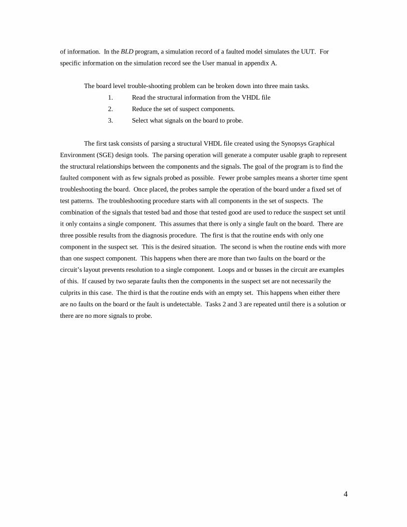
The good probe at signal 4 limits the influence sets of the bad signals. The Back walk column shows the
graph walk that produced the influence set. In this case, a simple walk can create the influence set. In most
cases the components that influence a signal’s value must be visited using a depth first search routine
bounded by good probe points. The signals in the back walk of each bad probe signal are used by the time
reduction routine. Notice that signal 3 is a member of the back walk for signal 6 and that the fault
indication time is 3 for both signals 3 and 6. From this information it can be concluded that signal 6’s fault
state is a combinational result of the fault state on signal 3. Signal 6 is moved from the bad probe set to the
good probe set. If you look at the back walk for signal 8 you will see that it includes signal 3. In this case
signal 8 has a fault indication time greater than signal 3. This means that signal 8’s fault indication
appeared later in time than signal 3’s fault indication. Since there is assumed to be only one fault in the
circuit signal 8’s fault indication must be in response to the indication on signal 3. Signal 8 is moved from
the bad probe set to the good probe set. Now the space reduction situation looks like that shown in Figure
4.
S T
2
5 6
7CLK
8Fa i l s @ T=3
B
C
AD
1 3
4E
3
InputsOutputs
Figure 4 Feedback example 2
When the space reduction algorithm is applied the result looks like this:
Good signals set 4,3,8Bad signal set 3
Bad Signals influence set Back Walk3 A A
Intersection A
Page 23
11
The good probe point on signal 8 blocks the back walk from signal 3 so that only component A is in its
influence set. This allows the program to conclude that component A is the faulted component.
3.4 Selecting signals on the board to probe
The decision of where to sample the signals is an important part of the diagnosis problem. The
method used can make the difference between finding the fault in a very few samples or having to sample
all the signals in the circuit. The most expensive part of the diagnosis process is the time spent placing the
probes. Therefore, it is to our advantage to discover the fault with as few probe samples as possible. The
circuit graph is partitioned in two different ways. The first is made up of only two sets and is formed by the
suspect and non-suspect sets. The other is by component distance from the output. Each level partition is
enumerated with the lowest level closest to the outputs and the highest near the inputs. The signals within
each level partition are selected as a group for the next sample. Only signals that are still in the suspect set
and cross through the desired level are selected. By partitioning the circuit graph into levels, the problem is
transformed from a complicated graph search problem into a simpler linear search problem.
ST
3
4
5
6
7
8
10
14
13
15
12
17
16
9
Inputs
Outputs
A
B
C
D
E
F
G
H
I
J
1
2
11
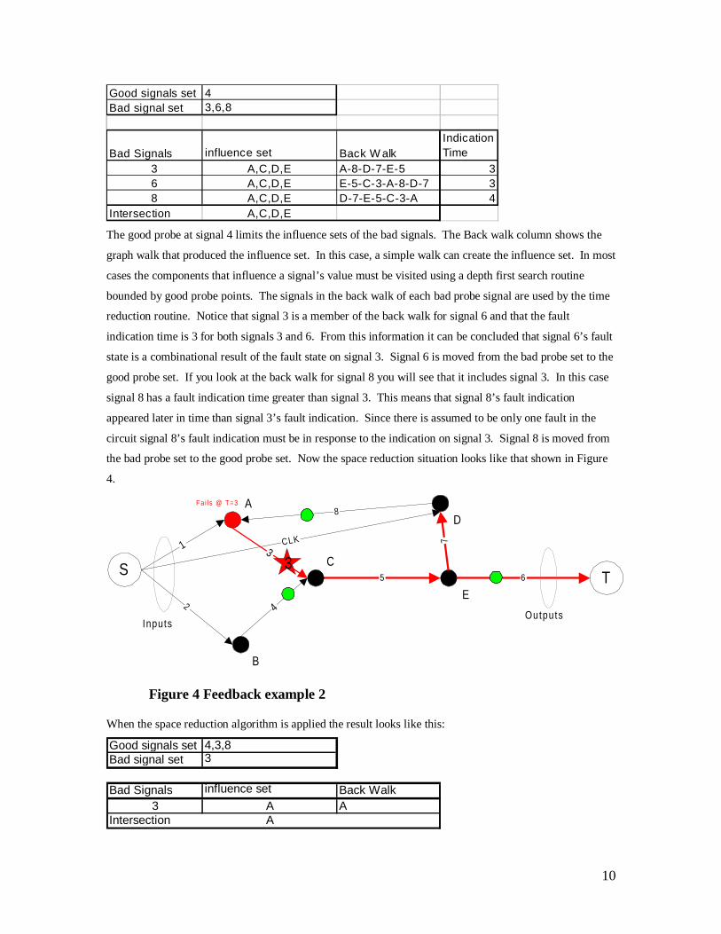
Figure 5 Probe example 1
Consider the circuit network shown in Figure 5. The yellow and red components mark the suspect
components within the network. Within this suspect area are 8 possible signals for probing. A human
observing this graph automatically tends to group the signals by their visual relationship. The computer is
not capable of doing this so easily. To the computer this graph is nothing more than a set of relationships
between signals and components. A depth first search of the suspect area starting from the suspect
components nearest the output toward the inputs partitions the suspect area into three different blocks.
Each block representing a group of components at the same level. A loose ordering on the blocks can be
assumed by the fact that those blocks with components nearest the outputs are effected by components in
the blocks further from the network output. This ordering converts the problem from a graph search
problem into an ordered list search problem. The suspect area in Figure 6 shows the network graph
partitioned by level. To probe level two the program would group the blocks into a new partition with
blocks B1 and B2. The block B1of the new partition would be those level blocks that represent levels 2 or
Page 24
12
greater while block B2 would be those level blocks representing levels 1 or less. Any signals that crossed
from B1 to B2 would be picked for the next probe cycle. In the case of the circuit in Figure 6 the block B1
would be{A,B,C} and block B2 would be {E,F,G,J,I}. The new probe signals would be {5,6,7,8}.
ST
3
4
5
6
7
8
10
14
13
15
12
17
16
9
Inputs
Outputs
A
B
C
D
E
F
G
H
I
J
1
2
11 0
12
Figure 6 Probe example 2
3.4.1. Leveling the suspect graph
When the new suspect space is determined by the fault set intersection method the new suspect
graph is a sub-graph of the original circuit graph. Due to the single fault assumption it can be assumed that
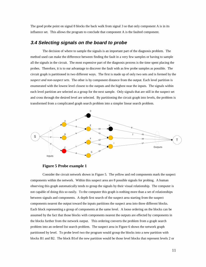
the new sub-graph is connected [3]. Consider the single fault example in Figure 7, the fault on component
C is propagated to the output signals 15 and 16. The sub-graph formed by the propagation paths of the C
fault creates a directed graph rooted at C. When the outputs of the circuit are probed, signals 15 and 16 will
be placed into the bad probe set. When suspect set reduction is performed two directed trees will be
created. The first directed tree will be rooted at signal 15 and back-propagate toward the inputs. It will
consist of the components {C, F, J}. The second directed tree will be rooted at signal 16 and back
propagate towards the inputs to create the influence set {C, F, G, I}. The intersection of these two
influence sets form the new suspect sub-graph with components {C, F}. The component/vertices of this
new sub-graph form a new tree that is a sub-tree of both of the original influence trees formed from signals
15 and 16. Being a tree, the new suspect graph is connected. If there is more than one fault in the circuit
the sub-graph formed by the intersection of the influence sets can be an empty set or a set of components
that may not include all of the faults. The empty set result is shown in the multiple fault example of Figure
7. In this case both components C and E are faulted and output signals 14, 15, and 16 are added to the bad
probe set. The influence sets formed by the directed trees rooted at these three signals are {A, B, E, H},
{C, F, J}, and {C,F , G, I}. The intersection of these three sets forms an empty set. To see a multiple fault
situation where the new suspect space contains no faulted components consider a situation where
components J and I are faulted in the network shown in Figure 7. The signals in the bad probe set would be
15 and 16. The influence sets would be {C, F, J} and {C, F, G, I}. The new suspect set formed by the
Page 25
13
intersection of these two influence sets would be {C, F}. In a situation like this it would be left up to the
technician to determine that there are two faults. In the author’s experience this multiple fault situation is
rare. In most cases where multiple faults occur the second fault is caused as a result of the first fault. This
means that the second fault is contained within the fault propagation path of the first fault. Running the
diagnosis program again after the first fault is repaired should discover the second fault. An example of
this would be if a fault in C caused damage to component J. The BLD would lead the technician to
component C. After repair the technician would discover that the circuit does not pass repair verification.
Running the BLD program on the circuit a second time would discover the fault in component J.
7
8
11
12
13
15
Single Fault
Multiple Fault
ST
3
4
5
6
7
8
10
13
12
14
1116
15
9
Inputs
Outputs
A
B
C
D
E
F
G
H
I
J
1
2
ST
3
4
5
6
10
14
9
Inputs
Outputs
A
B
C
D
E
F
G
H
I
J
1
2
16
Figure 7 Network examples
To simplify the probe selection problem the suspect sub-graph needs to be levelized. Levelizing
consists of repartitioning the signals and components of the graph according to their distance from the
output bridge signals. This starts by determining what signals in the suspect space are output bridge
Page 26
14
signals. Signals in the suspect space are output bridge signals when they are directed from the suspect
space to either a component in the non-suspect space or a circuit output. By scanning the list of all signals
in the circuit and creating a list of all signals that meet this requirement a new output bridge set is created.
Labeling the signals in the bridge set as ‘0’ the remainder of the suspect set is labeled by doing a depth first
search[3] from each of the signals in the bridge set. As each sub node is visited, it is labeled with a value
one greater than its parent [3] node.
3.4.2. Probe point selection methods
3.4.2.1.Binary Selection
The level partitioning of the circuit graph has transformed the graph into a list. Since there is a
causal relationship between the levels, the list of partitions can be considered ordered. A common
algorithm for searching an ordered list is the binary search algorithm. It works by dividing the search space
in half. With each probe cycle the search space is reduced by a half. When applied to the graph, the level
nearest the center of the suspect space is selected for the next sample. If none of the signals sampled show
a fault, then the fault is in the half nearest the output. Otherwise, it is in the half nearest the input. Also, if
it is in the half nearest the input there is a good possibility that the search space will be further reduced to
less than half of the original search space. The binary search algorithm has a complexity [3] of (log2N)[6].
3.4.2.2.Forward Selection
This method starts at the highest level, near the inputs, and works it’s way towards the outputs.
This is similar to how a technician would perform a diagnosis if he or she needed to learn the circuit. The
technician would verify the proper operation of each component by observing it’s output response for each
input pattern. While this method makes sense for a technician who is learning his/her way through a
circuit, it is not a practical alternative for a diagnostic program. With each level probed, only the
components at the current level have a possibility of being removed from the suspect set. The forward
selection method is synonymous to the sequential search algorithm, which has a complexity [3] of (N/2).
3.4.2.3.Backward Selection
The backward selection method is the opposite of the forward selection method. It starts at the
lowest level, near the outputs, and works its way toward the inputs. This method has the advantage of
reducing the fault down to the cone[1][7] of components leading to the apparent fault at the currently
sampled level. At the first sample, the suspect space is reduced according to the fan-in/fan-out
characteristics of the circuit. A new suspect space is found and the next samples are selected from the
Page 27
15
signals within the suspect sub-graph nearest the output. The backward selection method is synonymous to
the sequential search algorithm, which has a complexity [3] of (N/2).
3.4.2.4.Random Selection
The random selection method is here to provide a base line. The window term provided by the
user determines the number of signals sampled within each cycle. The signals are selected at random from
the current set of suspect signals.
Page 28
16
Figure 8 Suspect reduction with space intersection
Page 29
17
Figure 9 Simple IIR Schematic
Page 30
18
I_5
I_4
CLK
Reset
B0
X
A0
A0out
B0out
I_3 Zout I_2 buf_out
I_1
Z
Figure 10 Graph representation of Simple IIR filter model
Page 31
19
Chapter 4 Software Description
4.1 Overview
Written in the Java language, the Board Level Diagnosis program takes full advantage of the
languages object-oriented features. For details of the classes see Appendix C. The program is built of four
main modules. At its lowest level is the Java Utility package edu.vt.visc.util. It provides services that
handle the details of information storage and gathering. Here you will find data containers, parsers and
specialized data types. The next package up is the VHDL package. This package deals specifically with
handling the VHDL file and its information. Next is the BLT package. Here is a set of classes and their
tools for doing the actual work of the Diagnosis and reporting. It uses the classes from the utility and
VHDL packages to read, represent, and manipulate the VHDL model. The last and highest level class is
the visualBLD class. This class provides the user interface and uses the functions provided by the BLT
package to manipulate the circuit graph and report back to the user. This is not a package. It is a class that
uses these three specialized packages along with the Java API packages provided with the Java language to
create an interface.
VHDL fi le
entityport
architecture
body
port map
declarations
signal
component
port
configuration
1
2
3
4
5
6
3
7
edu.vt.visc.vhdl.vhdl1edu.vt.visc.vhdl.entity2edu.vt.visc.vhdl.port3
edu.vt.visc.vhdl.bitvector5edu.vt.visc.vhdl.architecture4
edu.vt.visc.vhdl.component6
6
edu.vt.visc.vhdl.configuration7
VHDL section to class association
VHDL f i le to parser breakdown
Figure 11 VHDL sections for parsing
Page 32
20
4.1.1. The VHDL parser
The nature of the VHDL parser is dictated by the structure of the VHDL file format. Seven
classes are used to represent the significant parts of the VHDL file’s sections. The box on the left side of
Figure 11 shows the sections of the VHDL file and the table on the right shows the classes associated with
each section. Created by the edu.vt.visc.vhdl.vhdl class, the viscStreamTokenizer opens the VHDL file and
breaks it down into a stream of tokens. The edu.vt.visc.vhdl.vhdl class then builds and stores the different
parts of the VHDL model by searching through this stream. Since the goal of this project was not to write a
VHDL parser, this parser is limited to a subset of the VHDL format output from the Synopsis Graphical
Environment. It is limited to reading structural VHDL models only.
When first created, this class opens the VHDL file and tokenizes it with the viscStreamTokenizer.
The viscStreamTokenizer is a rewritten version of the java.util.streamTokenzier that is included with the
Java language classes. Recognition of VHDL comments and word scanning were added to the tokenizer to
adapt it to reading VHDL files. Once the file is tokenized, the token stream is scanned for three specific
words, “entity”, “architecture”, and “configuration”. Each of these words represents the beginning of their
respective information sections. When the key word is found it is pushed back into the stream and the
tokenizer is passed into the constructor for the specified section object. An example would be if the entity
keyword were found. An entity object would be created and the tokenizer passed into it. After the entity
object is created it is stored in the vhdl object. As each new section is read a new object representing its
information is stored for later retrieval within the vhdl object. The entity, architecture and configuration
objects use the same technique for building their sub-sections. This continues until the end of file is
reached.
Page 33
21
visualBLD(Str ing[] args)
STEPblt .searching()
Initialize(String[] args)
Probe_Board( )
Reduce_search_space( ) Select_Probe_points()
Binary Mode High Level Flow diagram
arg[0] = <search mode>arg[1] = <vhdl_file>arg[2] = <board_record>arg[3] = <Simulation Record>
GetBoundryEdges(Enumerat ion N)Level ize(Enumerat ion N)
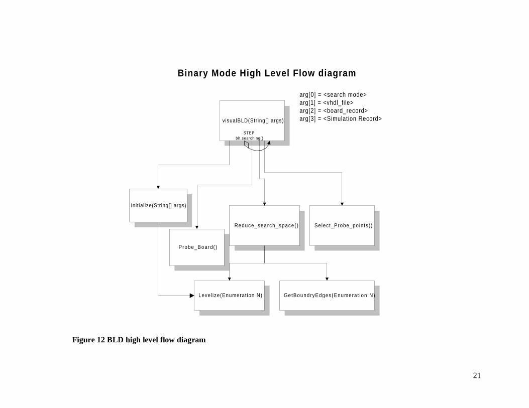
Figure 12 BLD high level flow diagram
Page 34
22
4.1.2. Board Level Diagnosis
Figure 12 shows a high-level block diagram of the Board Level Diagnosis program. The main
block represents the Board Level Diagnosis program itself. The other blocks represent procedures provided
by the edu.vt.blt package. The BLD starts by calling the Initialize procedure with the names of the required
file names. Once the Initialize procedure has finished preparing the circuit graph, the BLD waits until the
user selects the step button. When the step button is selected the methods in the search loop are performed.
The blt.searching method controls the activity of the search loop. If it returns false the loop is skipped and
a result is shown. If it returns true the next step in the diagnosis is performed. The step consists of probing
the board, reducing the suspect set, and selecting the next signals to be probed. When the step is completed
the BLD waits for the user to select the step button again.
The methods provided by the edu.vt.visc.blt package are associated with a class. Before these
methods can be used one of the classes provided by the edu.vt.visc.blt package must be instantiated. Which
class is instantiated determines what probe selection algorithm is used. An example of this is that if the
user decided to perform binary probe selection then the binary class would be instantiated and its methods
used to initialize and step through the process.
4.1.2.1. Binary mode
4.1.2.1.1. Initialize(String[] args)
The initialization routine does the following tasks:
1. Opens the VHDL file and builds the circuit graph.
2. Makes the first Probe set equal to the circuit outputs.
3. Makes the suspect set equal to all circuit components and makes the good set an empty
set.
4. Levelizes the entire graph by passing the primary outputs to the levelizing routine.
4.1.2.1.2. Blt.searching()(located in the visualBLD block)
Used by visualBLD, this method is used to stop the fault search when the solution is found or if
there doesn’t appear to be a solution. When the number of suspects is equal to 1 this returns false and ends
the fault search. This method also keeps a history of what signals were probed. If the probe selection
algorithm appears to be repeating itself then the search is stopped.
4.1.2.1.3. Reduce_search_space()
Page 35
23
The BLD program uses two algorithms to reduce the set of fault suspects. The first is the Space
Intersection method. This method creates a suspect set for each signal in the Bad Probe set by performing a
depth first search[3] towards the inputs. The search is bounded by either an input signal or a signal
contained in the Good Probe set. The intersection of all the influence sets associated with the signals in the
Bad Probe set produces a new suspect space for the next probe cycle. By using the time at which a bad
signal fails to further bound the depth first search, a second reduction method is created that can deal with
feed back loops. The first method is used by the binary, forward, backward and random search modes
while the second Time Domain method is used by the binary with loop detection search mode.
4.1.2.1.3.1.Space intersection
The space intersection method of suspect reduction uses the circuit’s structure and the probe
information to reduce the set of suspect components. The goal is to reduce the set of suspects with as little
probe information from the circuit as possible. The input and output signal information is not counted when
measuring the effectiveness of the space reduction. That information is considered to be free with out any
probing cost. The governing assumption of this process is that there is only one fault in the circuit. This is
a common assumption in test pattern generation and is considered to cover over 80% of most fault
situations[1]. One limit to the effectiveness of this procedure is that the fault reduction is no better than the
fault coverage of the test patterns applied. This means that the space intersection algorithm will not be able
to resolve any faults that are not covered by the input test patterns.
This method uses intersecting sets of propagation paths to reduce the suspect set. Probing is
performed by comparing the expected signal to the actual. A Bad Probe is when the expected and actual
don’t match. Figure 13 shows the set of components that could have possibly contributed to the Bad Probe
point P2. The set associated with P2 is {B, F, G, J, K, L, R, S, T, U, A1, B1, C1, D1, E1, K1, L1, M1, N1,
O1, P1}. The influence set associated with Bad Probe point P3 is {C, A3, A4, M, N, O, U, V, W, X, D1,
E1, F1, G1, H1, N1, O1, P1, Q1, R1, S1} and is illustrated in Figure 14 . The intersection of influence sets
P2 and P3 produces the reduced suspect space {U, D1, E1, N1, O1, P1} illustrated in Figure 15 . Figure 16
shows how the intersection space is further reduced by the addition of more probe information. Good probe
points limit the depth of the influence set built for each of the Bad Probe points. In this case the new
influence set for P2 is {B, F, G, J, K, L, R, S, T, U, A1, B1, C1, D1, E1, K1, L1, M1, N1} and the influence
set for P3 is {C, A3, A4, M, N, O, U, V, W, X, D1, E1, F1, G1, H1, P1, Q1, R1, S1}. The intersection of
these new sets is {U, D1, E1}. Before the influence sets are built for the Bad Probe points, each of the
Good Probe points are marked as visited. When the influence set for each Bad Probe point is built, the
program adds the components to the set as it visits them. It keeps going down deeper into the graph until it
reaches an input signal or it encounters a component that is already marked as visited.
Page 36
24
P 2P1 P3
3 4
Figure 13 Propagation Cone for P2
Page 37
25
P2P1 P3
3 4
Figure 14 Propagation cone for P3
Page 38
26
P2P1 P3
3 4
Figure 15 Intersection of P2 and P3
Page 39
27
P 2P 1 P3
3 4
Figure 16 Limiting space by probing
Page 40
28
4.1.2.1.3.2.Time domain reduction
By taking into consideration the time at which a fault indication first appears at a signal, the
algorithm is capable of breaking synchronous feedback loops. The premise under which the time domain
algorithm works is that the faulty component will produce the fault indication on its output signals first.
Fault indications on other signals will appear within the same sample cycle or in later sample cycles.
Within a set of Bad Probe samples, the members with the earliest indication time are closest to the source
of the fault. Those members without the minimum indication time can be moved from the Bad Probe set
into the Good Probe set. Signals in the Good Probe set are used to bound the space reduction. Once the
Bad Probe points have been reorganized by their indication times the space intersection method is used to
complete the space reduction.
A sequential component in a feed back loop is identified by the difference in time between the Bad
Probe indications before and after the faulted component. If the Bad Probe is before, the time of the Bad
Probe indication going into the sequential component will be earlier than the time of the Bad Probe
indication after the component. When this is encountered the indication after the component can be moved
from the Bad Probe set to the Good Probe set, breaking any loops and rapidly reducing the suspect space.
Like the space intersection method, once the suspect space is created the probe selection routine is used to
select the next signals to be probed.
4.1.2.1.4. Select_Probe_points()
To find the next set of signals to probe this method must first find the highest and lowest levels
within the suspect graph. Enumerating all the components in the suspect sub-graph and parsing through the
list does this. Once the minimum and maximum levels of the sub-graph are known the next probe level is
determined by taking the ceiling of the sum of the max and min levels divided by 2. All the signals that
cross this level value are then gathered up and stored as the next set of signals to probe. If the level value
were four, then any signals that crossed from components in level four to any component with a level
greater than four would be probed next.
The level values of the components represent a component’s place in the topology of the graph.
The probe selection algorithm may be made more efficient by re-leveling the components for each new
suspect sub-graph.
4.1.2.1.5. Probe_Board()
� �2maxmin�
�level
Equation 1 Binary level equation
Page 41
29
In the BLD, probing the board is a simple matter of scanning through the faulted and non-faulted
simulation records and comparing the requested signals. When a signal is compared bad it is tagged with
the time of the mismatch and added to the bad probe set. If compared good, it is added to the Good Probe
set. An external interface can easily be added by having the tester gather the information for the requested
signals and fill in the bad simulation record first. Then this routine can be called to evaluate the result of
the test.
4.1.2.1.6 Levelize (Vector graph, Vector outs)
This function assigns a level value to each of the graph components based on their depth from the
given list of output bridge components. The graph parameter is the list of components to be issued level
values. The outs parameter is the list of components with bridge signals for the selected sub-graph.
Components with bridge signals are called bridge components. If the outs parameter is null or empty then
all of the components with bridge signals for the desired sub-graph are used. A depth first search is
performed for each of the components in the outs list. The depth first search is implemented using a queue.
The search starts by initializing the level values of all components in the circuit to a negative number. And
setting the variable L to zero. Each of the components in the outs list is selected and if its level value is less
than zero its level is set to zero and a new path list is assigned to it. The new path list is initialized with the
new component as the only member. The selected component is then inserted into the queue. Continuing
until the queue is empty a component is removed from the queue and a list of its child components created.
The variable L is assigned the parents level value incremented by one. If the child’s level value is less than
L and the child is not in the parents path list then its level values is changed to L and is pushed into the
queue. Components that are not members of the graph list are not allowed into the queue. This limits the
levelizing routine to a sub-graph of the overall circuit graph.
Page 42
30
D
B
A
C
FE
outs = {A}graph = {A,B,C,D,E,F}
Figure 17 Levelizing
Consider the circuit in Figure 17 The first step is to initializes the level values of all the
components in the circuit to ‘-1’ and insert component A into the queue
Step 1. Q = {A}
Component Level Path
A 0 A
Step 2. Q={B,C}
Component Level Path
A 0 A
B 1 A,B
C 1 A,C
Step 3 Q={C,D,E}
Component Level Path
A 0 A
B 1 A,B
C 1 A,C
D 2 A,B,D
E1 2 A,B,E
Step 4. Q={D,E1,E2,F}
Component Level Path
A 0 A
B 1 A,B
C 1 A,C
D 2 A,B,D
E1 2 A,B,E
E2 2 A,C,E
F 2 A,C,F
Step 5. Q={E1,,E2,F}
Step 6. Q={E2,F}
Step 7. Q={F}
Step 8. Q={}
Component Level Path
A 0 A
B 1 A, B
C 1 A, C
D 2 A, B, D
E 2 A, B, E
F 2 A, C, F, [C]
Page 43
31
. Notice that in step 8, when the F component is removed from the queue that the child component C is not
placed into the queue. This is due to the fact that the C component was in F’s path list. If the path list had not
prevented the C component from entering the queue in step 8 then the algorithm would have entered an infinite loop.
4.1.2.2. Forward mode
The forward mode is a subclass of the binary mode. This means that it has inherited all of the attributes
and methods of the binary mode class. The forward probe algorithm is implemented by overriding the
Select_Probe_points method.
4.1.2.2.1. Select_Probe_points()
The forward search algorithm selects the signals in the suspect area closest to the inputs. This method
works by determining what the highest level is in the suspect area. It does this by scanning through the list of
components in the suspect sub-graph. It then builds a set of signals with the desired level value and saves it as the
next set of signals to be probed.
4.1.2.3. Backward mode
This mode is also a subclass of the binary mode. Taking the attributes and methods of the binary class it
overrides the Select_Probe_points method to implement the backward algorithm.
4.1.2.3.1. Select_Probe_points()
First the lowest level in the suspect graph is determined. This is usually zero, but just incase the levelizing
routine is changed the suspect sub-graph is still checked for the lowest component level. Then all components with
the desired level value are gathered up into a new probe set.
4.1.2.4. Random mode
4.1.2.4.1. Select_Probe_points()
Inheriting the attributes and methods of the binary mode this mode class implements a random level
selection routine. A window value provided by the user determines the number of signals probed within each
sample cycle. Signals from within the current suspect sub-graph are selected for probing at random until either the
required number of signals has been chosen or there are no more signals to choose from.
Page 44
32
Chapter 5 Results
5.1 Overview
Using the information from a structural VHDL model, and a record of the model’s simulation, the Board
Level Diagnosis program can determine the fault. As it stands now, the program must also use simulation data for
the faulted board. The visualBLD program itself is actually a very simple user interface that uses the tools contained
in the three specialized JAVA packages created. The real achievement is the tools themselves. If one looked at the
code for the visualBLD program, one would find a simple sequence of diagnosis commands associated with the step
button. The rest of the code is concerned with managing the interface and passing information about the circuit
from the diagnosis routines to the user. By using the diagnosis packages, the programmer is able to work at a higher
level of abstraction leaving most details to the tools in the packages.
The diagnostic routines themselves are demonstrated in the four probe algorithms provided. The core
diagnostic routine is the binary mode or edu.vt.visc.blt.binaryBLT class. This class contains all the methods and
variables to perform a binary search of the circuit. It uses the set intersection algorithm to reduce the suspect set.
All the other probe selection modes are extensions of the binary mode. The binary with loop detection is a radical
extension of the binary search routine. It extends the set intersection method with the addition of time intersection
routines. By considering the time of the first failure on a signal, as well as its location in the circuit, it is possible to
break feedback loops and resolve the fault to a single component.
5.2 Binary Mode, Array multiplier with I_21 fault
5.2.1. Step 1
This example demonstrates the binary mode applied to the four-bit array multiplier with component I_21
faulted. Figure 181 shows the first step of the diagnosis. All the outputs signals are sampled. The bad probes are
{P(7), P(6), P(5), P(4),}. They are annotated in the figure with red five pointed stars. The small green circles
annotate the good Probes. Backtracking, we get a set of components associated with each bad signal. This is the
signal’s input cone or influence set. The sets are:
1 You will notice that the numbering of the components in the figure is inconsistent. The SGE tool assigns
the component values as they are instantiated.
Page 45
33
Good Signals p(3),p(2),p(1),p(0)
Bad Signals Influence Set
P(7) i_17, i_18, i_19, i_20, i_21, i_22, i_23, i_24, i_25, i_26, i_27, i_28, i_29, i_30, i_31, i_32, i_33, i_34, i_35, i_36
P(6) i_18, i_19 ,i_20, i_21, i_22, i_23, i_24, i_25, i_26, i_27, i_28, i_29, i_30, i_31, i_32, i_33, i_34, i_35, i_36
P(5) i_18, i_19, i_21, i_22, i_23, i_24, i_26, i_27, i_28, i_29, i_30, i_31, i_32, i_33, i_34, i_35, i_36
P(4) i_18, i_21, i_22, i_23, i_26, i_27, i_28, i_30, i_31, i_32, i_33, i_34, i_35, i_36
Intersection Seti_18, i_21, i_22, i_23, i_26, i_27, i_28, i_30, i_31, i_32, i_33, i_34, i_35, i_36
The intersection of these influence sets defines the new suspect space. The new suspect components,
shown in Figure 18 by orange squares, have numbers on their right sides. These numbers represent the component’s
level within the new suspect space. The BLD program uses these numbers to calculate the next set of signals to
probe. By drawing a line through it, the suspect space of the circuit is divided in half. The line is represented by a
level value calculated as the ceiling of (0+4)/2 which is 2. To select the next signals to be probed the suspect space
must first be partitioned into two sub-graphs along the chosen level. The first block of the partition is the set of
component in the suspect space that have level values greater than or equal to 2. The second block of the partition
contains all components in the suspect space not in the first block. Any signals that cross from the first block to the
second block are added to the next set of signals to be probed. These are the signals that cross the chosen dividing
line. Non-suspect components are not members of ether of the two blocks of the partition. From Figure 18 you can
see that the CO and S outputs of components I_28, I_27, and I_26 cross the level two line. Looking at the close-up
of the circuit in Figure 19 you can see that the next signals to be probed will be N(17), N(18), N(19), and N(20).
Page 46
34
Figure 18 Binary Step 1
Page 47
35
Figure 19 Binary Step 1 Close up
Page 48
36
5.2.2. Step 2
After the signals in the new probe set are sampled signal N(17), on the S output of I_21, is added to the bad
probe set while signals N(18), N(19), and N(20) are added to the good probe set(Figure 20 ). The influence sets
associated with the bad probes are now:
Good Signals n(18), n(19), n(20), p(0), p(1), p(2), p(3)
Bad Signals Influence Set
P(7) i_17, i_18, i_19, i_20, i_21, i_22, i_23, i_24, i_25, i_28, i_29, i_32, i_33 ,i_36
P(6) i_18, i_19, i_20, i_21, i_22, i_23, i_24, i_25, i_28, i_29, i_32, i_33, i_36P(5) i_18, i_19, i_21, i_22, i_23, i_24, i_28, i_29, i_32, i_33, i_36P(4) i_18, i_21, i_22, i_23, i_28, i_32, i_33, i_36
N(17) i_21, i_28, i_32, i_33, i_36Intersection Set i_21, i_28, i_32, i_33, i_36
Notice how the Good Probed signal points N(18), N(19), and N(20), represented by green dots on the
outputs of components I_27 and I_26 in Figure 20, limit the area of the influence sets associated with each bad
probe point by blocking their backward expansion. Before the good probe points were established the components
I_27, I_26, I_31, I_30, I_34, and I_35 were members of the influence sets for P(7), P(6), and P(5). The intersection
of these five sets produces the new suspect space { i_21, i_28, i_32, i_33, i_36}.
The next probe level is the ceiling of (2+0)/2 which is 1. This makes the output signals of I_33 and I_32
candidates for the next probe signals. Looking at the close-up in Figure 21 you can see that the next signals to be
probed are N(0), and N(9).
Page 49
37
Figure 20 Binary Step 2
Page 50
38
Figure 21 Binary Step 2 Close up
Page 51
39
5.2.3. Step 3
In this step, the S output of I_33 signal N(0) and the CO output of I_32 signal N(9) are probed. The signal
N(0) is added to the bad probe set while signal N(9) is added to the good probe set.
Good Signals p(3), p(2), p(1), p(0), n(9), n(18), n(19), n(20)
Bad Signals Influence Set
P(7) i_17, i_18, i_19, i_20, i_21, i_22, i_23, i_24, i_25, i_28, i_29, i_33P(6) i_18, i_19, i_20, i_21, i_22, i_23, i_24, i_25, i_28, i_29, i_33P(5) i_18, i_19, i_21, i_22, i_23, i_24, i_28, i_29, i_33P(4) i_18, i_21, i_22, i_23, i_28, i_33N(0) i_21, i_33
N(17) i_21, i_28, i_33Intersection Set i_21 i_33
The intersections of the new influence sets form a new suspect space with components I_21 and I_33. As shown in
Figure 22, component I_33 has a level of 0 while component I_21 has a level of 1. The next probe level is the
ceiling of (0+1)/2 which is 1. The next signal to be probed is the CO output of the I_21 component. Looking at the
circuit close-up in Figure 23 you can see that the name of the next signal to be probed is N(8).
Page 52
40
Figure 22 Binary step 3
Page 53
41
Figure 23 Binary Step 3 close-up
Page 54
42
5.2.4. Step 4
In this step, signal N(8) on the CO output of component I_21 is probed and placed in the bad probe
set(Figure 24).
Good Signals n(18), n(19), n(20), n(9), p(0), p(1), p(2), p(3)
Bad Signals Influence Set
P(7) i_17, i_18, i_19, i_20, i_21, i_22, i_23, i_24, i_25, i_28, i_29, i_33P(6) i_18, i_19, i_20, i_21, i_22, i_23, i_24, i_25, i_28, i_29, i_33P(5) i_18, i_19, i_21, i_22, i_23, i_24, i_28, i_29, i_33P(4) i_18, i_21, i_22, i_23, i_28, i_33N(0) i_21, i_33
N(17) i_21, i_28, i_33
N(8) I_21Intersection Set I_21
The intersection of the bad probe influence sets leaves component I_21 in the suspect component
space. With only one component as a suspect the solution is I_21. Figure 25 offers a close-up view of the
result.
Page 55
43
Figure 24 Binary Step 4
Page 56
44
Figure 25 Binary Step 4 close-up
Page 57
45
5.3 Forward Mode, Array multiplier with I_21 fault
5.3.1. Step 1
This example demonstrates the forward mode applied to the four-bit array multiplier with component I_21
faulted. Signals P(0), P(1), P(2), P(3), P(4), P(5), P(6) and P(7) are sampled. The bad probes are {P(7), P(6), P(5),
P(4),} and the good probes are {P(0), P(1), P(2), P(3)}. The graph produced in the first step is the same as the one
produced in the first step of the last example since the same fault is used and the first signals probed are always the
outputs. See Figure 26. The probe selection routine in this mode picks the signals within the suspect space with the
highest level. In this case the next probe level is 4. The influence sets are again:
Bad Signal Influence Set
P(7) i_17, i_20, i_19, i_18, i_22, i_27, i_32, i_21, i_36, i_31, i_35, i_26, i_30, i_34, i_23, i_28, i_33, i_24, i_29, i_25
P(6) i_20, i_19, i_18, i_22, i_27, i_32, i_21, i_36, i_31, i_35, i_26, i_30, i_34, i_23, i_28, i_33, i_24, i_29, i_25
P(5) i_19, i_18, i_22, i_27, i_32, i_21, i_36, i_31, i_35, i_26, i_30, i_34, i_23, i_28, i_33, i_24, i_29
P(4) i_18, i_22, i_27, i_32, i_21, i_36, i_31, i_35, i_26, i_30, i_34, i_23, i_28, i_33
Intersection Seti_18, i_21, i_22, i_23, i_26, i_27, i_28, i_30, i_31, i_32, i_33, i_34, i_35, i_36
5.3.2. Step 2
With this step the program gets lucky. Since the faulted component was on the highest level it was quickly
found. {N(8), N(7), N(6), N(5), N(4), N(3), N(2)} is the set of signals at level four that are probed. Only N(8) was
added to the bad probe set. The influence set for the Bad Probe N(8) is only I_21. The intersection of this influence
set with the others produces the solution (Figure 27 and Figure 28).
Bad Signal Influence Set
P(7) i_17, i_18, i_19, i_20, i_21, i_22, i_23, i_24, i_25, i_26, i_27, i_28, i_29, P(6) i_18, i_19, i_20, i_21, i_22, i_23, i_24, i_25, i_26, i_27, i_28, i_29, i_30, P(5) i_18, i_19, i_21, i_22, i_23, i_24, i_26, i_27, i_28, i_29, i_30, i_31, i_32, P(4) i_18, i_21, i_22, i_23, i_26, i_27, i_28, i_30, i_31, i_32, i_33N(8) I_21
Intersection Set i_21
Page 58
46
Figure 26 forward Step 1
Page 59
47
Figure 27 forward Step 2
Page 60
48
Figure 28 forward Step 2 close up
Page 61
49
5.4 Random Mode, Array multiplier with I_21 fault
5.4.1. Step 1
This example demonstrates the operation of the random mode. Like all search routines it starts by reducing
the suspect space using only the information from the outputs. It then uses the window value set by the user to
select the next signals to be probed within the new suspect space. In this example the window value was set to 5.
This means that five signals within the suspect space will be selected at random for the next probe cycle. If there are
fewer than 5 signals within the probe space then all remaining signals will be sampled in the next cycle. Again the
output signals P(0), P(1), P(2), P(3), P(4), P(5), P(6) and P(7) are sampled with the same signals added to the bad
probe set. Since the I_21 fault is again used the influence sets for the first step are identical to those of the last two
steps: see Figure 26
Bad Signal Influence Set
P(7) i_17, i_20, i_19, i_18, i_22, i_27, i_32, i_21, i_36, i_31, i_35, i_26, i_30, i_34, i_23, i_28, i_33, i_24, i_29, i_25
P(6) i_20, i_19, i_18, i_22, i_27, i_32, i_21, i_36, i_31, i_35, i_26, i_30, i_34, i_23, i_28, i_33, i_24, i_29, i_25
P(5) i_19, i_18, i_22, i_27, i_32, i_21, i_36, i_31, i_35, i_26, i_30, i_34, i_23, i_28, i_33, i_24, i_29
P(4) i_18, i_22, i_27, i_32, i_21, i_36, i_31, i_35, i_26, i_30, i_34, i_23, i_28, i_33
Intersection Seti_18, i_21, i_22, i_23, i_26, i_27, i_28, i_30, i_31, i_32, i_33, i_34, i_35, i_36
5.4.2. Step 2
In this step signals N(2), N(4), N(10), N(12), and N(17) were probed with N(17) added to the Bad Probe
set(Figure 29 and Figure 30). The new influence sets are:
Bad Signal Influence Set
P(7) i_17, i_18, , i_19, i_20, i_21, i_22, i_23, i_24, i_25, i_26, i_27, i_28, i_29, i_30, i_31, i_32, i_33, i_35, i_36
P(6) i_18, i_19, i_20, i_21, i_22, i_23, i_24, i_25, i_26, i_27, i_28, i_29, i_30, i_31, i_32, i_33, i_35, i_36
P(5) i_18, i_19, i_21, i_22, i_23, i_24, i_26, i_27, i_28, i_29, i_30, i_31, i_32, i_33, i_35, i_36
P(4) i_18, i_21, i_22, i_23, i_26, i_27, i_28, i_30, i_31, i_32, i_33, i_35, i_36
N(17) i_21, i_28, i_32, i_33, i_36Intersection Set i_21, i_28, i_32, i_33, i_36
5.4.3. Step 3
Here signals N(0), N(6), N(7), N(8), and N(9) were probed with N(0) and N(8) added to the Bad Probe
set(Figure 31 and Figure 32). The influence sets are:
Page 62
50
Bad Signal Influence Set
P(7) i_17, i_18, i_19, i_20, i_21, i_22, i_23, i_24, i_25, i_26, i_27, i_28, i_29, i_30, i_31, i_33, i_35, i_36
P(6) i_18, i_19, i_20, i_21, i_22, i_23, i_24, i_25, i_26, i_27, i_28, i_29, i_30, i_31, i_33, i_35, i_36
P(5) i_18, i_19, i_21, i_22, i_23, i_24, i_26, i_27, i_28, i_29, i_30, i_31, i_33, i_35, i_36
P(4) i_18, i_21, i_22, i_23, i_26, i_27, i_28, i_30, i_31, i_33, i_35, i_36N(17) i_21, i_28, i_33N(0) i_21, i_33N(8) I_21
Intersection Set i_21
Since I_21 is the only element in the suspect set, the solution is I_21.
Page 63
51
Figure 29 random Step 2
Page 64
52
Figure 30 random Step 2 closeup
Page 65
53
Figure 31 random Step 3
Page 66
54
Figure 32 random Step 3 close up
Page 67
55
5.5 Binary with loop detection, IIR filter with I_3 faulted
This is a demonstration of the binary with loop detection procedure on the simple IIR filter model.
In this model I_1 is the sequential element within the loop and component I_3 is faulted. While following
the time domain reduction routine you should remember that the input patterns are being applied in an
ordered sequence from 0 to n. With each probe test the same set of test patterns are applied in the exact
same order. The times of failures associated with each bad probe signal is the enumeration value of the test
pattern that was being applied at the time the difference in the expected and actual values was discovered.
5.5.1. Step 1
Again, the BLD program starts with the signals on the output. Figure 33 shows the results of the
first sampling. The red dots on the signal lines represent bad probes and the green dots represent good
probes. As the program progresses, bad probe points from the last step are changed to orange dots and
good probe points from the last step are changed to blue dots. The main difference between this algorithm
and the binary method is that timing information is used. The numbers next to the signals indicate the time
of the first detected signal mismatch between the expected and actual value. In the simulation record the
signal events are stored in a 0 to n array with the first event at 0. The value n is equal to the number of
input patterns applied minus 1. The numbers next to the signals indicate the position in the event array at
which the mismatch occurred. For example, the times of failures for the signals in the BUF_OUT bus are
(18, 0, 0, 21). This means that signals BUF_OUT(2) and BUF_OUT(1) failed while the first set of input
patterns were applied. BUF_OUT(3) failed while input pattern 18 was being applied and BUF_OUT(0)
failed while input pattern 21 was being applied. Each of the components have a number on their right side
that indicates its level value. The next probe level will be the ceiling of (0+3)/2 which is 2. The set of
suspect components is the intersection of the influence sets formed by the signals in the bad probe set.
Notice that the Good and bad probe sets have been modified by the time domain reduction algorithm before
the new suspect set was created. Two suspect sets are created. The first set, S1, is the intersection of the
bad probe influence sets before time domain reduction is applied. The second set, S2, is the intersection of
the bad probe influence sets after time domain reduction. The intersection of S1 and S2 produces the new
suspect set. The set S1 captures the suspect set created by all of the signals that probed bad while the S2
captures a suspect set created by the bad probe signals closest to the fault in time and distance.
Page 68
56
Probed Signals buf_out(0), buf_out(1), buf_out(2), buf_out(3)
Bad Signals buf_out(0), buf_out(1), buf_out(2), buf_out(3)Good Signals
Bad Signals Influence Set Fault Timebuf_out(0) i_1, i_2, i_3, i_4, i_5 21buf_out(1) i_1, i_2, i_3, i_4, i_5 0buf_out(2) i_1, i_2, i_3, i_4, i_5 0buf_out(3) i_1, i_2, i_3, i_4, i_5 18
Intersection Set S1 i_1, i_2, i_3, i_4, i_5
Bad Signals buf_out(1), buf_out(2)Good Signals buf_out(0), buf_out(3)
Bad Signals Influence Set Fault Timebuf_out(1) i_1, i_2, i_3, i_4, i_5 0buf_out(2) i_1, i_2, i_3, i_4, i_5 0
Intersection Set S2 i_1, i_2, i_3, i_4, i_5Intersection of S1 and S2 i_1, i_2, i_3, i_4, i_5
Before Time Domain testing
After Time Domain testing
Page 69
57
18,0,0,21
01
2
2
3
Figure 33 Binary w/ loop detection Step 1
Page 70
58
5.5.2. Step 2
Figure 34 shows the result of probing at level 2. The numbers next to the Bad Probe points
indicate the times of the first failure indications. The time domain reduction routine starts with the most
recently acquired signals and searches within its input cone for other signals that are marked Bad. For
B0OUT(7) in Figure 34 , the failure time is 76. Taking this as the root of a tree, backtrack into the circuit
to form a list of all other signals marked as bad within its input cone. If any of these other signals have a
time mark less than or equal to the root signal then the root signal is moved from the bad probe set into the
good Probe set. This is done to B0OUT(7), B0OUT(6) , B0OUT(5) , B0OUT(4) , B0OUT(3) , B0OUT(2) ,
B0OOUT(1), B0OUT(0), BUF_OUT(3) and BUF_OUT (0). This leaves signals BUF_OUT (2) and
BUF_OUT (1) in the bad probe set. The influence sets associated with these signals are:
Bad Signals
b0out(0), b0out(1), b0out(2), b0out(3), b0out(4), b0out(5), b0out(6), b0out(7), buf_out(0), buf_out(1), buf_out(2), buf_out(3)
Good Signalsa0out(0), a0out(1), a0out(2), a0out(3), a0out(4), a0out(5), a0out(6), a0out(7)
Bad Signals Influence Set Fault Timebuf_out(0) i_1, i_2, i_3, i_5 21buf_out(1) i_1, i_2, i_3, i_5 0buf_out(2) i_1, i_2, i_3, i_5 0buf_out(3) i_1, i_2, i_3, i_5 18
b0out(0) i_1, i_3, i_5 88b0out(1) i_1, i_3, i_5 18b0out(2) i_1, i_3, i_5 31b0out(3) i_1, i_3, i_5 20b0out(4) i_1, i_3, i_5 18b0out(5) i_1, i_3, i_5 33b0out(6) i_1, i_3, i_5 31b0out(7) i_1, i_3, i_5 76
Intersection Set S1 i_1, i_3, i_5
Bad Signals buf_out(1), buf_out(2)Good Signals a0out(5), a0out(6), a0out(7), b0out(0), b0out(1),
Bad Signals Influence Set Fault Timebuf_out(1) i_2, i_3 0buf_out(2) i_2, i_3 0
Intersection Set S2 i_2, i_3Intersection of S1 and S2 I_3
Before Time Domain testing
After Time Domain testing
The intersection of S1 and S2 results in the diagnosis solution I_3. This is a good example of
where the combination of non-time reduced data and time reduced data leads the program to the correct
solution.
Page 71
59
76 ,31 ,33 ,18 ,20 ,31,18,88
z(3:0)
zout(7:0)b0out(7:0)
a0out(7:0)
buf_out(3:0)
I_1I_5
I_4
I_3 I_2
18,0,0,21
Figure 34 Binary w/ loop detection Step 2
Page 72
60
5.6 Binary with loop detection, IIR filter with I_1 faulted
This example demonstrates a limitation of the loop detection algorithm. In the previous example
the faulted component was a combinational component within a loop with only a single sequential element.
When there is only one sequential element in the loop, and it is faulted, the time domain reduction
algorithm fails. In this example the single sequential component within the loop, I_1, fails. The fault
propagates from the source, around the loop and back to the source within one sample cycle. This means
that all of the faulted signals within the loop will have the same fault indication time. With no differing
fault indication time the algorithm lacks enough information to make a single component diagnosis.
5.6.1 Step 1
As you can see in Figure 35 the program again starts with the outputs. The next probe level is the
ceiling of (0+3)/2= 2. The following table summarizes the fist probe step for this fault. The time domain
algorithm determines the minimum fault indication time within the bad probe set. Any bad probe set
members with fault indication times greater than the minimum time are moved to the good probe set. Next,
a depth first search is performed on each of the remaining members of the bad probe set. If another
member of the bad probe set is encountered with a higher level value then the parent signal of the search
with the lower level value is moved to the good probe set
Probed Signals buf_out(0), buf_out(1), buf_out(2), buf_out(3)
Bad Signals buf_out(0), buf_out(1), buf_out(2), buf_out(3)Good Signals
Bad Signals Influence Set Fault Timebuf_out(0) i_1, i_2, i_3, i_4, i_5 20buf_out(1) i_1, i_2, i_3, i_4, i_5 20buf_out(2) i_1, i_2, i_3, i_4, i_5 18buf_out(3) i_1, i_2, i_3, i_4, i_5 18
Intersection Set S1 i_1, i_2, i_3, i_4, i_5
Bad Signals buf_out(3), buf_out(2)Good Signals buf_out(0), buf_out(1)
Bad Signals Influence Set Fault Timebuf_out(2) i_1, i_2, i_3, i_4, i_5 18buf_out(3) i_1, i_2, i_3, i_4, i_5 18
Intersection Set S2 i_1, i_2, i_3, i_4, i_5Intersection of S1 and S2 i_1, i_2, i_3, i_4, i_5
Before Time Domain testing
After Time Domain testing
5.6.2 Step 2
In Figure 36, level 2 is probed and time domain reduction was applied leaving a bad probe set of {
b0out(0), b0out(1), b0out(2), b0out(3), b0out(4), b0out(5)}.
Page 73
61
The new suspect area is {I_1, I_3, I_5}. The next probe level is the ceiling of (0+2)/2=1.
Probed Signals
a0out(0) ,a0out(1), a0out(2), a0out(3), a0out(4), a0out(5), a0out(6), a0out(7), b0out(0), b0out(1), b0out(2), b0out(3), b0out(4), b0out(5), b0out(6), b0out(7)
Bad Signals
b0out(0), b0out(1), b0out(2), b0out(3), b0out(4), b0out(5), b0out(6), b0out(7), buf_out(0), buf_out(1), buf_out(2), buf_out(3)
Good Signalsa0out(0), a0out(1), a0out(2), a0out(3), a0out(4), a0out(5), a0out(6), a0out(7)
Bad Signals Influence Set Fault Timebuf_out(0) i_1, i_2, i_3, i_5 20buf_out(1) i_1, i_2, i_3, i_5 20buf_out(2) i_1, i_2, i_3, i_5 18buf_out(3) i_1, i_2, i_3, i_5 18
b0out(0) i_1, i_3, i_5 18b0out(1) i_1, i_3, i_5 18b0out(2) i_1, i_3, i_5 18b0out(3) i_1, i_3, i_5 18b0out(4) i_1, i_3, i_5 18b0out(5) i_1, i_3, i_5 18b0out(6) i_1, i_3, i_5 21b0out(7) i_1, i_3, i_5 62
Intersection Set S1 i_1, i_3, i_5
Bad Signalsb0out(0), b0out(1), b0out(2), b0out(3), b0out(4), b0out(5)
Good Signals
a0out(0), a0out(1), a0out(2), a0out(3), a0out(4), a0out(5), a0out(6), a0out(7), b0out(6), b0out(7), buf_out(0), buf_out(1), buf_out(2), buf_out(3)
Bad Signals Influence Set Fault Timeb0out(0) i_1, i_3, i_5 18b0out(1) i_1, i_3, i_5 18b0out(2) i_1, i_3, i_5 18b0out(3) i_1, i_3, i_5 18b0out(4) i_1, i_3, i_5 18b0out(5) i_1, i_3, i_5 18
Intersection Set S2 i_1, i_3, i_5Intersection of S1 and S2 i_1, i_3, i_5
Before Time Domain testing
After Time Domain testing
5.6.3 Step 3
Level 1 is probed and time domain reduction is applied leaving only signals z(0) and z(3) in the
Bad Probe set. The intersection of sets S1 and S2 produces the new suspect space of {I_1, I_3}. The next
probe level is the ceiling of (0_1)/2=1(Figure 37).
Page 74
62
Probed Signals z(0), z(1), z(2), z(3)
Bad Signals
b0out(0), b0out(1), b0out(2), b0out(3), b0out(4), b0out(5), b0out(6), b0out(7), buf_out(0), buf_out(1), buf_out(2), buf_out(3), z(0), z(1), z(2), z(3)
Good Signalsa0out(0), a0out(1), a0out(2), a0out(3), a0out(4), a0out(5), a0out(6), a0out(7)
Bad Signals Influence Set Fault Timebuf_out(0) i_1, i_2, i_3, i_5 20buf_out(1) i_1, i_2, i_3, i_5 20buf_out(2) i_1, i_2, i_3, i_5 18buf_out(3) i_1, i_2, i_3, i_5 18
b0out(0) i_1, i_3, i_5 18b0out(1) i_1, i_3, i_5 18b0out(2) i_1, i_3, i_5 18b0out(3) i_1, i_3, i_5 18b0out(4) i_1, i_3, i_5 18b0out(5) i_1, i_3, i_5 18b0out(6) i_1, i_3, i_5 21b0out(7) i_1, i_3, i_5 62
z(0) i_1, i_3, i_5 18z(1) i_1, i_3, i_5 31z(2) i_1, i_3, i_5 84z(3) i_1, i_3, i_5 18
Intersection Set S1 i_1, i_3, i_5
Bad Signals z(0), z(3)
Good Signals
a0out(0), a0out(1), a0out(2), a0out(3), a0out(4), a0out(5), a0out(6), a0out(7), b0out(0), b0out(1), b0out(2), b0out(3), b0out(4), b0out(5), b0out(6), b0out(7), buf_out(0), buf_out(1), buf_out(2), buf_out(3), z(1), z(2)
Bad Signals Influence Set Fault Timez(0) i_1, i_3 18z(3) i_1, i_3 18
Intersection Set S2 i_1, i_3Intersection of S1 and S2 i_1, i_3
Before Time Domain testing
After Time Domain testing
5.6.4. Step 4
Again, level 1 is probed(Figure 38). The following table summarizes the reduction results. Take
note of the members in set S1. That is not a mistake. The new suspect set must always be a subset of the
current suspect set. If you look back at the suspect set created by the last step you will see that it is {I_1,
I_3}.
Page 75
63
Probed Signals zout(6)
Bad Signals
b0out(0), b0out(1), b0out(2), b0out(3), b0out(4), b0out(5), b0out(6), b0out(7), buf_out(0), buf_out(1), buf_out(2), buf_out(3), z(0), z(1), z(2), z(3), zout(0), zout(1), zout(2), zout(3), zout(4), zout(5), zout(6), zout(7)
Good Signalsa0out(0), a0out(1), a0out(2), a0out(3), a0out(4), a0out(5), a0out(6), a0out(7)
Bad Signals Influence Set Fault Timebuf_out(0) i_1, i_2, i_3, i_5 20buf_out(1) i_1, i_2, i_3, i_5 20buf_out(2) i_1, i_2, i_3, i_5 18buf_out(3) i_1, i_2, i_3, i_5 18
b0out(0) i_1, i_3, i_5 18b0out(1) i_1, i_3, i_5 18b0out(2) i_1, i_3, i_5 18b0out(3) i_1, i_3, i_5 18b0out(4) i_1, i_3, i_5 18b0out(5) i_1, i_3, i_5 18b0out(6) i_1, i_3, i_5 21b0out(7) i_1, i_3, i_5 62
z(0) i_1, i_3, i_5 18z(1) i_1, i_3, i_5 31z(2) i_1, i_3, i_5 84z(3) i_1, i_3, i_5 18
zout(0) i_1, i_3, i_5 18zout(1) i_1, i_3, i_5 18zout(2) i_1, i_3, i_5 20zout(3) i_1, i_3, i_5 20zout(4) i_1, i_3, i_5 18zout(5) i_1, i_3, i_5 18zout(6) i_1, i_3, i_5 21zout(7) i_1, i_3, i_5 44
Intersection Set S1 i_1, i_3
Bad Signals zout(0) ,zout(1), zout(4), zout(5)
Good Signals
a0out(0), a0out(1), a0out(2), a0out(3), a0out(4), a0out(5), a0out(6), a0out(7), b0out(0), b0out(1), b0out(2), b0out(3), b0out(4), b0out(5), b0out(6), b0out(7), buf_out(0), buf_out(1), buf_out(2), buf_out(3), z(0), z(1), z(2), z(3), zout(2), zout(3), zout(6), zout(7), Bad Set, zout(5), zout(4), zout(1), zout(0)
Bad Signals Influence Set Fault Timezout(0) i_3 18zout(1) i_3 18zout(4) i_3 18zout(5) i_3 18
Intersection Set S2 i_3Intersection of S1 and S2 i_3
Before Time Domain testing
After Time Domain testing
Page 76
64
With only a single member in the suspect set the search routine ends. Normally when the search
routine ends, any components remaining in the suspect set are returned as the result. In this case that would
result in the wrong answer. From a technician’s perspective a wrong answer is worst than no answer. If
the program returned I_3 as the faulted component the technician would waste his/her time troubleshooting
the wrong component. To prevent this, a time loop search is performed on the components in the suspect
set. This works by taking the time of failure of the suspect component and searches backwards along any
paths with the same failure time. If the path of times returns to the original component then a time loop has
been detected. All components within the time loop are moved back into the suspect set. Once each of the
components in the original suspect set have been tested for time loops, the new suspect set is returned as
the program result. Looking at Figure 39 you will notice that components I_5, I_3 and I_1 are marked as
suspect. These three components were discovered to be members of a time loop. Looking at the failure
times for Z(0), Zout(0) and B0Out(0) you will see that they all failed at time 18. The important thing to
remember when the program returns a time loop solution is that only one of the returned components is
sequential. Find that sequential component and you’ve found the fault. Since the BLD doesn’t have that
information, it is left up to the technician to determine which of the suspects returned is the faulted
component. This is much better than the other alternative. The program has given a good answer in that
the technician is still on the correct path to the fault.
Page 77
65
18,18,20,20
01
2
2
3
Figure 35 I_1 fault Step 1
Page 78
66
18,18,20,20
62,21,18,18,18,18,18,18
01
2
Figure 36 I_1 fault Step 2
Page 79
67
18,18,20,20
62,21,18,18,18,18,18,18
0
1
18,84,31,18
Figure 37 I_1 fault Step 3
Page 80
68
18,18,20,20
62,21,18,18,18,18,18,18
0
18,84,31,18
14,21,18,18,20,20,18,18
Figure 38 I_1 fault step 4a
Page 81
69
18,18,20,20
62,21,18,18,18,18,18,1818,84,31,18
44,21,18,18,20,20,18,18
Figure 39 I_1 fault Step 4b
Page 82
70
5.7 Binary Mode, Busser with I_6 faulted
This example demonstrates how the program deals with faults that appear on a bus. The model is
made up of four data sources whose outputs are gated onto the bus through tri-state buffers. The fault in
the tri-state buffer I_6 causes the buss line B(4) to always be high. Since the Diagnosis program has no
way to tell which component is driving a signal it will be unable to resolve the fault to any one component.
The best solution the program can give to the technician is those components on the bus that could be
driving the faulted signals.
5.7.1 Step 1
In the first step all of the output signals are probed and signal B(4) is added to the Bad Probe
set(Figure 40). The influence set for B(4) is all components in the circuit. Level 2 is selected for the next
probe cycle.
Bad Signal Influence SetB(4) i_8, i_1, i_4, i_3, i_2, i_7, i_6, i_5
5.7.2 Step 2
After probing level 2 no new signals are added to the Bad Probe set (Figure 41). The signals
data_3(15:0), data_2(15:0), data_1(15:0), wnext(3), and read(3:1) are added to the Good Probe set and
limits the influence set of B(4) to {I_1, I_5, I_6, I_7, I_8}. Level 1 is selected for the next probe cycle.
Bad Signal Influence SetB(4) i_8, i_7, i_6, i_5, i_3
Notice that the signals DATA_0(15:0), READ(0), DATA_1(15:0), READ(1), DATA_3(15:0), and
READ(3) are probed as well as the signal WNEXT(2). This is a good example of how the probe selection
routine selects the next signals to be probed. Any signals that start on a component labeled with the level 2
or greater and end on either an output or a component with a level label greater than 2 is selected.
5.7.3 Step 3
Here signals data_0(15:0), and read(0) are added to the Good Probe set (Figure 42). This further
limits the influence set of B(4) to {I_5, I_6, I_7, I_8}. These are the components that directly drive the
signals in the Bad Probe set. At this point, it is left up to the technician to resolve the fault to one of these
four components. In the author’s experience, the only way to determine which of these four components is
faulted is to remove them from the system one at a time until the fault indication changes.
Bad Signal Influence SetB(4) i_8, i_7, i_6, i_5
Page 83
71
0 0 0 0
1 23 4
0
Figure 40 Busser Step 1
Page 84
72
0 0 0 0
1
0
Figure 41 Busser Step 2
Page 85
73
Figure 42 Busser Step 3
Page 86
74
5.8 Tables of Results
These tables summarize the performance of the Board Level diagnosis program in its five different
modes with five different `models. The first two columns of the table describe the model under test and the
search mode used. Columns three through seven describe the physical characteristics of the circuit. Eight
through ten describe the fault characteristics and the last three columns show the performance of the chosen
mode for the given fault. The ‘levels’ value indicates the number of levels within the circuit while the
‘Fault level’ column gives the depth of the inserted fault from the output.
5.8.1 MPU2 results
The MPU2 model represents 16-bit math processor unit. It has 57 inputs, 16 outputs with a total
of 67 signals. Table 1 shows a summery of each of the five search modes applied to two different faults.
The first fault is the alu_34 component. This fault is two levels from the input and located within a
feedback loop. Since the fault is in a loop only the binary with loop detection mode can effectively
discover the fault. Out of a total of 67 signals to probe the binary with loop detection mode resolved the
fault to a single component by probing 24 signals in three steps. The second fault is the crt_14 module.
This component is deeper into the circuit from the outputs at level 3 and is not located in a loop. Since the
fault is not located in a loop all but the backward search mode are able to reduce the fault to a single
component. Notice that the steps and number of signals probed are the same for both binary modes. In
this case the time domain reduction algorithm used in the binary with loop detection mode provided no
advantage to finding the problem. The best mode in this case is the forward search mode with 35 signals
probed in 3 steps. The worst mode is the backward mode with 33 signals probed in 3 steps with 5 suspects
remaining.
5.8.2 4 bit Array multiplier results
This model represents a 4-bit array multiplier. This is a purely combinational circuit with no
feedback. The first fault shown in Table 2 is I_17 faulted. This component is on level 0, which means that
it is directly connected to the output. All of the search modes resolved the fault to a single suspect. Oddly
enough only the backward mode performed better than the random search mode. The forward mode
performed the worst with 31 signals probed in 8 steps. This poor performance is due to the fault’s distance
from the inputs. This forced the forward mode to sample all of the signals between the inputs and the
outputs before it acquired any relevant data to form a resolution. The backward mode performed the best
with 2 signals sampled in two steps. Again this was caused by the faults location within the circuit. The
second example in Table 2 is the I_21 fault. This fault is the inverse of the I_17 fault by being at the
deepest possible level near the inputs. In this case the random mode did poorly while the forward and
backward modes show little difference between them. While the backward mode didn’t do as well in the
Page 87
75
I_17 fault, it did not do as poorly as the forward mode. The forward mode got the best solution with 7
signals probed in two steps. The worst solution was the Random mode with 10 signals probed in 3 steps.
5.8.3 UART results
Table 3 shows a summery of the UART model under the I_1 and I_4 faults. The UART model is
made up of two separate sequential circuits. The first circuit performs parallel to serial transformations
while the second performs serial to parallel transformations. The I_1 fault is located 1 level from the
output and is not in a loop. In this case all of the search modes were able to resolve the fault to a single
component by only observing the outputs. Since no internal signals were probed a 0 appears in the signals
sampled column. Remember that input and output signals are not counted as probed signals. The I_4 fault
is 3 levels from the output and is located within a time-loop. This means that I_4 is the only sequential
element in the loop and it is faulted. This causes all of the components within the loop to have the same
time of failure. In this case it is left up to the technician to determine which of the two components within
the loop are the fault. There is no way for the program to determine which component is the fault with only
structural information. The backward mode performed the best with only 1 signals probed in two steps
while the binary and forward modes performed the worst with 2 signals probed in 4 steps.
5.8.4 IIR Filter results
Table 4 shows the results from a simple IIR filter with I_1 or I_5 faulted. For the first example
I_1 is faulted. I_1 is the only sequential element in a feed back loop. Since it is faulted the fault times for
all of the components within the loop are the same. In all five modes the program returns the three signals
within the loop. By the numbers the forward performed the best with only 20 signals probed in 4 steps
while the binary mode performed the worst with 28 signals probed in 5 steps. In a real situation the results
from neither of these two modes would be trusted since it is known that the circuit contains feedback loops.
The binary with loop detection mode returned the solution after probing all 28 signals within the circuit in 4
steps. this performance might seem poor but if you consider that 71% of the circuit internal signals are
within the loop you can understand why all of them were probed. The fault I_5 is 2 levels from the output
and is a non-sequential component located within a loop. Again, since this is a feedback circuit the results
returned by the search modes other than the binary with feedback are suspect. The best performer was the
binary with feed back mode with 20 signals in 3 steps with 1 suspect. The worst performer was the binary
mode with 28 signals in 5 steps with 3 suspects.
5.8.5 Busser results
The busser model demonstrates how the program deals with signals that can have more than one
driving component. The output bus B has 16 bits, which can be driven by any of the four tri-buff
components I_5, I_6, I_7 or I_8. Normally only one of these four components drives the bus at any one
time. When one of the components driving the bus fails and drives the bus out of turn there is no way to
Page 88
76
determine which of the four components on the bus are faulted by passively probing the bus. the best that
the BLD program can do is notify the technician which components are most likely causing the fault and let
him or her resolve the problem. Table 5 shows the different search modes applied to the Busser model with
I_6 faulted. This fault causes I_6 to always drive a ‘1’ onto pin 4 of the bus. since the circuit has a loop in
it only the binary with feedback solution can be trusted. In all five search modes the components driving
the common bus are returned as the suspects. The backward mode performed the best by probing 68
signals in 2 steps and the random mode performed the worst by probing all the signals in 16 steps. The
binary mode probed 69 signals in 4 steps.
Page 89
77
Table 1 MPU2 results
ModelSearch Mode
Levels Loops #Inputs #Outputs #Signals FaultFault Level
Fault in Loop
#Signals Sampled
#Steps Result
MPU2 Binary 4 1 57 16 67 alu_34 2 yes 67 4 i_2, reg_28, alu_34
Forward 33 3crt_14, muxp1_22, i_2, reg_28, alu_34
Backward 33 3crt_14, muxp1_22, i_2, reg_28, alu_34
Random(5) 67 15 i_2, reg_28, alu_34
Binary w/ Loop
Detection24 3 alu_34
Binary crt_14 3 no 51 3 crt_14
Forward 35 3 crt_14
Backward 33 3crt_14, muxp1_22, i_2, reg_28, alu_34
Random(5) 40 9 crt_14
Binary w/ Loop
Detection51 3 crt_14
Page 90
78
Table 2 4 bit Array Multiplier results
ModelSearch Mode
Levels Loops #Inputs #Outputs #Signals FaultFault Level
Fault in Loop
#Signals Sampled
#Steps Result
4 bit Array Multiplier
Binary 7 0 8 8 31 I_17 HA 0 no 11 4 I_17
Forward 31 8 I_17
Backward 2 2 I_17
Random(5) 9 3 I_17
Binary w/ Loop
Detection11 4 I_17
Binary I_21 cell 7 no 7 4 I_21
Forward 7 2 I_21
Backward 7 5 I_21
Random(5) 10 3 I_21
Binary w/ Loop
Detection7 4 I_21
Page 91
79
Table 3 UART results
ModelSearch Mode
Levels Loops #Inputs #Outputs #Signals FaultFault Level
Fault in Loop
#Signals Sampled
#Steps Result
UART Binary 3 1 15 11 11I_1
cnt_dnz1 no 0 1 i_1
Forward 0 1 i_1
Backward 0 1 i_1
Random(5) 0 1 i_1
Binary w/ Loop
Detection0 1 i_1
Binary I_4 in_con 3 time loop 2 4 I_5, I_4
Forward 2 4 I_5, I_4
Backward 1 2 I_5, I_4
Random(5) 2 2 I_5, I_4
Binary w/ Loop
Detection2 3 I_5, I_4
Page 92
80
Table 4 IIR Filter results
ModelSearch Mode
Levels Loops #Inputs #Outputs #Signals FaultFault Level
Fault in Loop
#Signals Sampled
#Steps Result
IRR filter Binary 3 1 14 4 28 i_1 REG4 3 time loop 28 5 i_5, i_3, i_1
Forward 20 4 i_5, i_3, i_1
Backward 24 3 i_5, i_3, i_1
Random(5) 28 7 i_5, i_3, i_1
Binary w/ Loop
Detection28 4 i_5, i_3, i_1
Binaryi_5
MUX_MULT
2 yes 28 5 i_5, i_3, i_1
Forward 20 4 i_5, i_3, i_1
Backward 24 3 i_5, i_3, i_1
Random(5) 28 7 i_5, i_3, i_1
Binary w/ Loop
Detection20 3 I_5
Page 93
81
Table 5 Busser results
ModelSearch Mode
Levels Loops #Inputs #Outputs #Signals FaultFault Level
Fault in Loop
#Signals Sampled
#Steps Result
Busser Binary 4 0 1 16 72I_6
tribuffer0 no 69 4 I_8, I_7, I_6, I_5
Forward 71 6 I_8, I_7, I_6, I_5
Backward 68 2 I_8, I_7, I_6, I_5
Random(5) 72 16 I_8, I_7, I_6, I_5
Binary w/ Loop
Detection69 4 I_8, I_7, I_6, I_5
Page 94
82
Chapter 6 Conclusions
The results shown in Tables 1 through 5 highlight the BLD’s strength and weaknesses. The
binary, forward, random and binary with loop detection modes will always find a single solution in a non-
feedback combinational circuit. With the addition of loops to the problem, only the Binary mode with loop
detection can do the job consistently. For the rare case when there is a single sequential component in the
loop, and it is faulted, all of the components in the loop are returned. A problem that may be more
common is the bus resolution problem. It is impossible to determine which device is improperly driving a
shared signal by purely passive probing. The best this program can do is to provide the technician with a
list of suspect devices. In most of the test cases shown a large percentage of the circuit’s signals were
probed. In the authors opinion this problem is due to the small size of the models used. Of the five modes
tested the binary with loop detection appears to be the most reliable. It will always return a good solution
with a fair amount of work. While the binary with loop detection mode rarely outperformed all of the other
search modes it can also be seen to have rarely been the worst. While the solution returned is not always a
single fault it is the author’s opinion that it is better to give the technician an incomplete answer than to
return a wrong answer.
Chapter 7 Proposed Future Work
This research represents a good start on the board level diagnosis problem. This project offers a
good set of tools for working with the diagnosis problem. It is the authors hope that this body of work can
be used in the future by others investigating solutions to this problem.
7.1 Technician interface for real world use
Currently the BLD program uses simulation data from a faulted VHDL model to represent the
faulted board. Due to a lack of resources and time no real board interface was developed. What is needed
is a JAVA module that can take the probe set from the BLD and probe the UUT. Once the signal data is
gathered from the UUT it can be inserted into the faulted simulation table where the VHDL simulation
currently goes. This would require very little actual change to the BLD program as it now stands.
7.2 EDIF file parser
Adding a parser capable of reading the EDIF file format would allow the BLD to accept circuit
information from almost any commercial design tool. This would make the tool more commercially viable.
It was decided that while the EDIF parser would be an improvement that it was not really required to meet
the goals of the current project. EDIF files can also include graphical information for the circuit. If used,
the graphical information from the EDIF file could be used in place of the circuit graphic file currently
used. With no need for a graphic image the IDC could also be retired.
Page 95
83
7.3 Implement Meryem Marzouki’s fuzzy qualitative probe
point selection algorithm[4]
The algorithm described by Meryem Marzouki in his paper “System fault diagnosis based on a
fuzzy qualitative approach” shows promise as a very effective probe selection strategy. The functionality of
the BLD as it stands now would provide an excellent platform for investigating the effectiveness of
Marzouki’s approach.
7.4 Improve bitvector entry in the IDCCurrently the IDC breaks up bitvectors into individual bits. This requires the user to place each
and every bit. This can become tedious for large models. A method can be added to the IDC that allows
the user to select and place slices of bitvectors. Should a full EDIF parser be implemented it is possible to
do away with the IDC altogether.
Page 96
84
References
[1] M. Abramovici, M. Breuer, A. Friedman, Digital Systems Testing and Testable Design,
IEEE Press, 1995.
[2] P. Ashenden, The Designer’s Guide to VHDL, Morgan Kaufman Publishers, Inc., 1996.
[3] G. Chartran, O. Oellermann, Applied and Algorithmic Graph Theory, McGraw-Hill, Inc.,
1993.
[4] M. Touati, F. Mohamed, and M. Marzouki. “System fault diagnosis based on a fuzzy
qualitative approach,” European Design and Test Conference, Paris, France March 1996.
[5] G. Booch, Object solutions: managing the object-oriented project, Addison-Wesley Pub.
Co., 1996
[6] H. Wilf, Algorithms and Complexity , Prentice-Hall, Englewood Cliffs, NJ 1986.
[7] F. Hsu, P. Solecky, and R. Beaudoin, “Structured Trace Diagnosis for LSSD Board
Testing --- An Alternative to Full Fault Simulated Diagnosis,” Proc. 18th Design
Automation Conf., pp. 891-897, June 1981.
[8] M. Abramovici, “A Hierarchical, Path-Oriented Approach to Fault Diagnosis in Modular
Combinational Circuits,” IEEE Trans. On Computers Vol. C-31, No. 7 pp. 672-677, July
1982
[9] M. Abramovici and M. Breuer, “Fault Diagnosis in Synchronous Sequential Circuits
Bases on an Effect-Cause Analysis,” IEEE Trans. On Computers, Vol. C-31, No. 12 pp
1165-1172, December, 1982.
[10] R. Davis, “Diagnostic Reasoning Based on Structure and Behavior,” Artificail
Inteligence, Vol. 24, pp 347-410, December, 1984.
[11] S. Kochan, N. Landis, and D. Monson, “Computer-Guided Probing Techiniques,” Digest
of Papers 1981 Intn’l Test Conf., pp 253-268, October, 1981.
Page 97
85
[12] I. Koren and Z. Kohavi, “Sequential Fault Diagnosis in Combinational Networks,"”
IEEE Trans. oN Computers, Vol. C-26, No. 4, pp. 334-342, April 1977.
[13] E. Purcell, “Fault Diagnosis Assistant,” IEEE Circuits and Devices Magazine, Vol. 4,
No. 1, pp. 47-59, January, 1988.
[14] J. Rajski, “GEMINI – A Logic System for Fault Diagnosis Based on Set Functions,”
Digest of Papers 18th Intn’l Symp. On Fault-Tolerant Computing, pp. 292-297, June,
1988.
[15] A. Wilkinson, “A Method for Test System Diagnostics Based on the Principles of
Artificial Intelligence,” Proc. Intn’l Test Conf., pp188-195, October, 1984.
[16] J. Gosling, B. Joy, G. Steel, The JavaTM Language Specification, © Sun Microsystems,
Inc., Addison-Wesley, August, 1996.
[17] C. Horstmann, G. Cornell, Core Java 1.1, Volume 1-Fundamentals, © Sun
Microsystems, Inc., Sun Microsystems Press, 1996.
Page 98
86
Appendix A. Users Guide
1. Program overview
The board level diagnosis program uses probe selection and suspect reduction algorithms to
discover the faulty component on a digital board. A VHDL model created by the Synopsys Graphical
Environment program describes the logic of the board. This program allows the user to place and wire the
board as symbols in a user-friendly graphical environment. The chips of the board are represented as
component symbols in the model. Each of the components are modeled by a VHDL entity architecture
pair. To help the Board Level Diagnostic (BLD) program display its progress the circuit schematic is
captured and saved in a GIF or JPG file. The Image Data Creator (IDC) program creates a data file for the
BLD using the graphic file and the VHDL model. The BLD program takes the VHDL model, a data file
created by the IDC, and a simulation table created by the VHDL simulator and performs a suspect search
using the desired algorithms.
1.1 Features
There are five modes available binary, binary with feed back, forward, backward, and random.
The forward, backward and random modes are only for comparison purposes and are less useful than the
binary modes. The binary with feed back mode is an extension of the binary mode. The capability to
reduce fault spaces with feedback has been added.
A. Supported search modes
1. Binary Mode
The binary mode uses the divide and conquer technique to rapidly diagnose the problem to a
single chip or component. The program starts out with all components in the suspect space. A sampling of
the outputs reduces the suspects to some smaller space. Within this new space the binary algorithm selects
signals that are nearest to the halfway point between the inputs and outputs of the suspect space. This
guarantees that the next suspect space will be at least half the size of the current one. Utilizing space
reduction techniques the next space is almost always much less than half of the current space. The
disadvantage to this mode is that it is unable to reduce suspect spaces containing feed back. This limitation
is solved by the binary with feed back mode. It is an extension of this mode that utilizes fault times as well
as locations to reduce the suspect space.
2. Binary with Feedback
Page 99
87
Using the time of the fault as well as its location, this mode breaks feedback loops within the
suspect space. When a fault occurs in a loop it is assumed that there is some sequential element within the
loop. A single fault within the loop causes all signals in the loop to appear faulted. The solution is to look
at the time at which the first fault is sensed. Any sequential element in the loop will cause the sensed time
of any faults later in the loop to be delayed in time. By ordering the fault signals in the loop by time and
keeping only the earliest, the loop can be broken into a smaller non-feedback fault space. Once the
feedback is removed, normal search and space reduction can proceed. An added benefit to the time
resolution algorithm is that multiple propagation paths in a non-feedback circuit are quickly removed early.
This reduces the number of probes required in non-feedback circuits.
3. Forward Mode
This mode simply selects the next set of probe points by testing the outputs of the components in
the suspect space nearest the inputs. The method is similar to a list search that searches from the beginning
of a list and moves forward.
4. Backward Mode
The backward mode is like the forward mode accept the probe points are selected from the inputs
of the components nearest the output. This is similar to a list search that starts at the end of a list and
moves towards the beginning.
5. Random Mode
In this mode the suspect space is divided into levels of components. Each component is labeled in
accordance with its distance from the outputs. Once the suspect space is partitioned into levels, one is
picked at random and returned as the next probe set.
B. Written in Java
The BLD program is written in JAVA version 1.1. This provides the capability of
compiling it once and running it on virtually any platform. Using the Java language's
object oriented approach, the BLD program was written as sets of easily interchangeable
modules. An example of this is the search mode. Each of the search modes are
independent modules that utilize the services of other utility modules to perform the
probe selection task. When you as a user select a search mode the desired module is
plugged in and the program is started. Even the VHDL parser is a plug in module. If in
the future it is desired to read a circuit description in another format a new module for it
can be written and inserted in place of the VHDL parser module.
Page 100
88
C. Command line interface
The BLD program also accepts command line arguments. By selecting the mode and input files
from the command line the program can be started without needing to use the slower source selection
window. The command line format is as follows:
java visualBLD -<mode> <vhdl file> <unfaulted table> <faulted table> <image data file>
<mode>=> 2|f|b|r#|B
-2 : binary
-f :forward
-b : backward
-r# :random
-B binary w/ loop
#=> random number seed.
2. Installation
2.1 Java
To run the BLD program you must first have a Java virtual machine environment. This is simply a
Java virtual machine program and it's associated library of standard classes. These can be easily obtained
over the Internet for free from http://www.javasoft.com. The BLD programs visual interface is written in
Java version 1.1. This requires that you install a version of Java that is version 1.1 or higher. The
instructions for installing and running the Java environment are included with the download package.
2.2 BLD
The BLD program class library is packaged in the visualBLD.jar file. You add this file to your
classpath like this:
"CLASSPATH=.;C:\ VisualCafeWDE\BIN\COMPONENTS\SYMBEANS.JAR;C:\Visual
CafeWDE\JAVA\LIB\CLASSES.ZIP;C:\VisualCafeWDE\JAVA\LIB ; C:\Java\visual BL
D.jar "
This is a copy of the class path on the author’s machine. Yours will probably
look nothing like this. What is important is the item that has been appended to the end of
the already existent path. This guides the Java interpreter to the visualBLD program and
Page 101
89
it's libraries. To run the BLD program type "java visualBLD" on the command line. To
use the IDC program type "java ImageDataCreator" on the command line.
3. Image Data Creator walk through
To use the BLD program you need to have a data file for the model. This data file provides
information to the BLD program used to annotate it's progress to the user. It contains a graphic
representation of the circuit along with an index that associates each signal and component name with an x-
y position on the graphic. What the IDC program will do is get the names of the signals from the VHDL
model and allow you to pick where you want the signals to be marked on the schematic during the
troubleshooting simulation.
Figure 43 Starting the IDC
3.1 Starting the program
You start the program by changing directory to where your image and VHDL files are located and
typing java ImageDataCreator. Once the program starts select New->VHDL file from the file menu. Then
select the VHDL model desired. For this example select simpiir_loop.vhd. Then select 'File->New->Image
File' from the menu and select the schematic image file for your model (simpiir_loop.gif). Figure 44
shows the program with the VHDL model parsed and the image loaded. It is now waiting for you to
associate the signals with points on the graphic.
Page 102
90
OBUF
z(3:0)
zout(7:0)
bout(7:0)
Aout(7:0)
buf_out(3:0)
I_1
I_2I_3
I_4
I_5
Figure 44 IDC open
Page 103
91
3.2 Placing points on the graphic
Looking in the upper left hand corner of Figure 44 , you will notice a text box with a signal name
in it. On the right of the text box is an indicator informing you of the number of markers left to be placed.
Find the signal or component on the schematic whose name matches the one shown in the text box and
mark it with the left mouse button. If you don't like the placement of the marker you can move it by right
clicking on the marker. If you place the first marker by left clicking, the name in the text box will change
to the next signal in the list. When you right click on the marker the name in the text box is replaced with
the name of the marker you clicked. There are no bit vectors in the list. They have been broken down into
their individual bits. This means that for bus signals you will have a marker for every bit in the bus. This
can become tedious and time consuming. Try to be consistent on how you mark signals. This will help you
later when you run the BLD program. Any ambiguity here can lead to confusion later on. Figure 45 shows
the completely marked schematic. The text box says done and the number of signals left is zero. Save the
data file with the same name as the VHDL model file but with a .dat ending. (simpiir_loop.dat)
Page 104
92
I_2
I_1
I_3
I_4
I_5
z(3:0)
zout(7:0)
b0out(3:0)
a0out(3:0)
Figure 45 Marking complete
Page 105
93
4. Board Level Diagnostic walk through
4.1 Starting the program
Once the models and data file are done the BLD program is simple to operate. To start the
program type "java visualBLD" on the command line. Pay attention to the capital letters, the java
interpreter is case sensitive. Next, select File->Open and click on the button marked "…" next to the
VHDL file text box. This opens a file selection dialog where you can select the VHDL model file. For this
example select simpiir_loop. Notice that when you click on Open and the file selection dialogue closes that
the file name selected is put in the VHDL file text box. Also notice that the Data file text box is filled in
with the VHDL file’s name appended with the .dat ending. This is a convenience and is why you should
name your data file after your VHDL file. Using the "…" buttons next to each of the text boxes fill in the
rest of the fields. An example of a completed Source dialogue box is shown in Figure 47 . Notice that the
search mode selected is binary with loop detection. The simpiir_loop model has a feed back loop in it and
the binary search mode is unable to find the fault. To see the difference in modes try this model with both
search modes. The .tab files were created using the Synopsys VHDL simulator. The no-fault file is a
simulation run made with the non-faulted model and the simpliir_I1.tab file was made with a model that
had the component I1 faulted. See the section “5. Creating table files from model simulations” for
instruction on making the .tab file.
Page 106
94
Figure 46 Opening dialogue boxes
Figure 47 Source dialogue
Page 107
95
4.2 Stepping through the simulation
If you have completed the opening dialogue boxes correctly you should see something like Figure
48. Notice the yellow squares centered over the component symbols. These squares are markers that
indicate the symbol’s status as a suspect. When the symbol is no longer a suspect the marker color is
changed to green. Left click on the Step button to select the first set of probe points. The signals closest to
the output are selected first. This allows the space reduction routine to survey the entire circuit space and
make a good first cut at reducing the suspects. The probe points selected are marked with red or blue
circles. The red circles indicate probe points that did not match the non-faulted simulation while the blue
ones matched. Orange and green circles indicate failed and passed probed signals from previous probe
selection cycles. Continue to hit step until a dialogue box appears. As you step through the simulation you
will notice the reduction of the suspect space by the yellow squares turning green. When the program is
finish a dialogue box appears displaying the search results (Figure 49). Select OK to close the dialogue
box. You can start another simulation by repeating the open procedure that starts by selecting the File-
>Open menu item.
Page 108
96
Figure 48 Ready to start the search
Page 109
97
Figure 49 Search complete
5. Creating table files from model simulations
The table files are records of the VHDL models under a fixed set of test patterns.
The author’s tables were created by using a IEEE WAVES test bench to drive the models
with different configurations. Each configuration represented a different fault state of the
model. Running the Synopsys simulator in a Solaris environment the author created a
table file as follows:
guitar (7) /project/tpals3/crockett/simpleiir > vhdlsim
CFG_test_bench_SIMPIIR_LOOP_test
Synopsys 1076 VHDL Simulator Version 1998.02 -- Jan 05, 1998
Copyright (c) 1990-1996 by Synopsys, Inc.
ALL RIGHTS RESERVED
This program is proprietary and confidential information
of Synopsys, Inc. and may be used and disclosed only as
authorized in a license agreement controlling such use
and disclosure.
# ls
TEST_BENCH STD_LOGIC_ARITH WAVES_1164_FRAMES
STANDARD WAVES_1164_UTILITIES WGP_SIMPIIR_LOOP
Page 110
98
TEXTIO WAVES_1164_DECLARATIONS
STD_LOGIC_COMPONENTS
ATTRIBUTES WAVES_INTERFACE VHDLCAD
STD_LOGIC_1164 UUT_TEST_PINS _KERNEL
STD_LOGIC_MISC WAVES_OBJECTS
# cd test_bench
# ls
WAVES U1
WAV_STIM_X
_P0 MONITOR_BUF_OUT FAIL_SIGNAL
_P1 SIMPIIR_LOOP
WAV_EXPECT_BUF_OUT
_P2 WAV_STIM_A0 ACTUAL_BUF_OUT
_P3 WAV_STIM_B0 WPL
_P4 WAV_STIM_CLK
_P5 WAV_STIM_RESET
# cd u1
# ls
A0 X I_3 A0OUT
OBUF
B0 BUF_OUT I_4 ZOUT
ADD2
CLK I_1 I_5 Z
MUX_MULT
RESET I_2 B0OUT REG4
# trace -o simpiir_loop_nofault.ow *'sig
# run
(vhdlsim): Simulation complete, time is 5040000 PS.
# quit
guitar (8) /project/tpals3/crockett/simpleiir > wif2tab -oh
simpiir_loop_nofault.ow simpiir_loop_nofault.tab
Synopsys 1076 VHDL WIF2TAB Version 1998.02 -- Jan 05, 1998
Copyright (c) 1990-1996 by Synopsys, Inc.
ALL RIGHTS RESERVED
This program is proprietary and confidential information
of Synopsys, Inc. and may be used and disclosed only as
authorized in a license agreement controlling such use
and disclosure.
Page 111
99
guitar (9) /project/tpals3/crockett/simpleiir >
CFG_test_bench_SIMPIIR_LOOP_test is the name of the configuration
associated with the non faulted simpiir_loop model. Once the simulator is started the
author had to CD from the test benches level down to the model’s level in the hierarchy.
From there a trace was set up that would log all signal events within the model to a wif
format file. Once the simulation is run, quit and use the wif2tab program to convert the
wif binary file into a text table that the BLD program can read. The table must be in this
format for the BLD program to read it. No other format is currently supported. The
simulation command and wif2tab programs are documented in the Synopsys online
user’s manuals. Be sure to use the -oh option in the wif2tab program or the BLD will not
be able to read it.
Appendix B. VHDL Models
1. Simple IIR Filter
The simple IIR filter model represents a Second order filter. All components in this model are
combinational with the exception of I_1 located in the feedback loop. The test bench conforms to the IEEE
WAVES level 1 standard.
1.1 Model
1. Simpiir_loop file
-- VHDL Model Created from SGE Schematic simpiir_loop.sch -- Apr 19 01:00:32 1998
library IEEE;
use IEEE.std_logic_1164.all;
use IEEE.std_logic_misc.all;
use IEEE.std_logic_arith.all;
use IEEE.std_logic_components.all;
use WORK.VHDLCAD.all;
entity SIMPIIR_LOOP is
Page 112
100
Port ( A0 : In std_logic_vector (3 downto 0);
B0 : In std_logic_vector (3 downto 0);
CLK : In std_logic;
RESET : In std_logic;
X : In std_logic_vector (3 downto 0);
BUF_OUT : Out std_logic_vector (3 downto 0) );
end SIMPIIR_LOOP;
architecture SCHEMATIC of SIMPIIR_LOOP is
signal B0OUT : std_logic_vector(7 downto 0);
signal A0OUT : std_logic_vector(7 downto 0);
signal ZOUT : std_logic_vector(7 downto 0);
signal Z : std_logic_vector(3 downto 0);
component REG4
Port ( A : In std_logic_vector (7 downto 0);
CLK : In std_logic;
RST : In std_logic;
Z : Out std_logic_vector (3 downto 0) );
end component;
component OBUF
Port ( A : In std_logic_vector (7 downto 0);
Z : Out std_logic_vector (3 downto 0) );
end component;
component ADD2
Port ( A : In std_logic_vector (7 downto 0);
B : In std_logic_vector (7 downto 0);
Z : Out std_logic_vector (7 downto 0) );
end component;
component MUX_MULT
Port ( A : In std_logic_vector (3 downto 0);
B : In std_logic_vector (3 downto 0);
Z : Out std_logic_vector (7 downto 0) );
end component;
begin
I_1 : REG4
Page 113
101
Port Map ( A(7 downto 0)=>ZOUT(7 downto 0), CLK=>CLK, RST=>RESET,
Z(3 downto 0)=>Z(3 downto 0) );
I_2 : OBUF
Port Map ( A(7 downto 0)=>ZOUT(7 downto 0),
Z(3 downto 0)=>BUF_OUT(3 downto 0) );
I_3 : ADD2
Port Map ( A(7 downto 0)=>B0OUT(7 downto 0),
B(7 downto 0)=>A0OUT(7 downto 0),
Z(7 downto 0)=>ZOUT(7 downto 0) );
I_4 : MUX_MULT
Port Map ( A(3 downto 0)=>X(3 downto 0),
B(3 downto 0)=>A0(3 downto 0),
Z(7 downto 0)=>A0OUT(7 downto 0) );
I_5 : MUX_MULT
Port Map ( A(3 downto 0)=>Z(3 downto 0),
B(3 downto 0)=>B0(3 downto 0),
Z(7 downto 0)=>B0OUT(7 downto 0) );
end SCHEMATIC;
configuration CFG_SIMPIIR_LOOP_SCHEMATIC of SIMPIIR_LOOP is
for SCHEMATIC
for I_1: REG4
use configuration WORK.CFG_REG4_BEHAVIORAL;
end for;
for I_2: OBUF
use configuration WORK.CFG_OBUF_BEHAVIORAL;
end for;
for I_3: ADD2
use configuration WORK.CFG_ADD2_BEHAVIORAL;
end for;
for I_4, I_5: MUX_MULT
use configuration WORK.CFG_MUX_MULT_BEHAVIORAL;
end for;
end for;
end CFG_SIMPIIR_LOOP_SCHEMATIC;
configuration CFG_SIMPIIR_LOOP_I1_FAULTED of SIMPIIR_LOOP is
for SCHEMATIC
Page 114
102
for I_1: REG4
use configuration WORK.CFG_REG4_FAULT;
end for;
for I_2: OBUF
use configuration WORK.CFG_OBUF_BEHAVIORAL;
end for;
for I_3: ADD2
use configuration WORK.CFG_ADD2_BEHAVIORAL;
end for;
for I_4, I_5: MUX_MULT
use configuration WORK.CFG_MUX_MULT_BEHAVIORAL;
end for;
end for;
end CFG_SIMPIIR_LOOP_I1_FAULTED;
configuration CFG_SIMPIIR_LOOP_I2_FAULTED of SIMPIIR_LOOP is
for SCHEMATIC
for I_1: REG4
use configuration WORK.CFG_REG4_BEHAVIORAL;
end for;
for I_2: OBUF
use configuration WORK.CFG_OBUF_FAULT;
end for;
for I_3: ADD2
use configuration WORK.CFG_ADD2_BEHAVIORAL;
end for;
for I_4, I_5: MUX_MULT
use configuration WORK.CFG_MUX_MULT_BEHAVIORAL;
end for;
end for;
end CFG_SIMPIIR_LOOP_I2_FAULTED;
configuration CFG_SIMPIIR_LOOP_I3_FAULTED of SIMPIIR_LOOP is
for SCHEMATIC
for I_1: REG4
use configuration WORK.CFG_REG4_BEHAVIORAL;
end for;
for I_2: OBUF
Page 115
103
use configuration WORK.CFG_OBUF_BEHAVIORAL;
end for;
for I_3: ADD2
use configuration WORK.CFG_ADD2_FAULT;
end for;
for I_4, I_5: MUX_MULT
use configuration WORK.CFG_MUX_MULT_BEHAVIORAL;
end for;
end for;
end CFG_SIMPIIR_LOOP_I3_FAULTED;
2. ADDER
-- VHDL Model Created from SGE Symbol add2.sym -- Apr 19 00:53:26 1998
library IEEE;
use IEEE.std_logic_1164.all;
use IEEE.std_logic_misc.all;
use IEEE.std_logic_arith.all;
use IEEE.std_logic_components.all;
use WORK.VHDLCAD.all;
entity ADD2 is
Port ( A : In std_logic_vector (7 downto 0);
B : In std_logic_vector (7 downto 0);
Z : Out std_logic_vector (7 downto 0) );
end ADD2;
architecture BEHAVIORAL of ADD2 is
begin
Z<=ADD(A,B);
end BEHAVIORAL;
configuration CFG_ADD2_BEHAVIORAL of ADD2 is
for BEHAVIORAL
end for;
end CFG_ADD2_BEHAVIORAL;
-----------------------------------------
Page 116
104
architecture FAULT of ADD2 is
begin
Z<=shiftl(ADD(A,B),'0');
end FAULT;
configuration CFG_ADD2_FAULT of ADD2 is
for FAULT
end for;
end CFG_ADD2_FAULT;
3. MUX_MULT
-- VHDL Model Created from SGE Symbol mux_mult.sym -- Apr 19 00:46:07 1998
library IEEE;
use IEEE.std_logic_1164.all;
use IEEE.std_logic_misc.all;
use IEEE.std_logic_arith.all;
use IEEE.std_logic_components.all;
use WORK.VHDLCAD.all;
entity MUX_MULT is
Port ( A : In std_logic_vector (3 downto 0);
B : In std_logic_vector (3 downto 0);
Z : Out std_logic_vector (7 downto 0) );
end MUX_MULT;
architecture BEHAVIORAL of MUX_MULT is
begin
process(A,B)
begin
Z<= MULT(A,B);
end process;
end BEHAVIORAL;
configuration CFG_MUX_MULT_BEHAVIORAL of MUX_MULT is
for BEHAVIORAL
end for;
Page 117
105
end CFG_MUX_MULT_BEHAVIORAL;
------------------------------------------------
architecture FAULT of MUX_MULT is
begin
process(A,B)
begin
Z<= shiftl(MULT(A,B),'0');
end process;
end FAULT;
configuration CFG_MUX_MULT_FAULT of MUX_MULT is
for FAULT
end for;
end CFG_MUX_MULT_FAULT;
4. OBUF
-- VHDL Model Created from SGE Symbol obuf.sym -- Apr 19 00:54:18 1998
library IEEE;
use IEEE.std_logic_1164.all;
use IEEE.std_logic_misc.all;
use IEEE.std_logic_arith.all;
use IEEE.std_logic_components.all;
use WORK.VHDLCAD.all;
entity OBUF is
Port ( A : In std_logic_vector (7 downto 0);
Z : Out std_logic_vector (3 downto 0) );
end OBUF;
architecture BEHAVIORAL of OBUF is
begin
Z<=A(5 downto 2);
end BEHAVIORAL;
configuration CFG_OBUF_BEHAVIORAL of OBUF is
for BEHAVIORAL
Page 118
106
end for;
end CFG_OBUF_BEHAVIORAL;
----------------------------------
architecture FAULT of OBUF is
begin
Z(3)<=A(2);
Z(2)<=A(3);
Z(1)<=A(4);
Z(0)<=A(5);
end FAULT;
configuration CFG_OBUF_FAULT of OBUF is
for FAULT
end for;
end CFG_OBUF_FAULT;
1.2 Test bench
1. Header
-- **************************************************
--
-- ******** Header File for Entity: SIMPIIR_LOOP
--
-- **************************************************
-- **************************************************
--
-- Data Set Identification Information
--
TITLE A General Description
DEVICE_ID SIMPIIR_LOOP
DATE Sun Apr 19 01:14:36 1998
ORIGIN Company X Design Team
AUTHOR Company or Person
AUTHOR Maybe Multiple ... Companies or People
Page 119
107
DATE Sun Apr 19 01:14:36 1998
ORIGIN Modified by Company X Design Team
AUTHOR Who did it Company or Person
OTHER Any general comments you want
OTHER Built Using the WAVES-VHDL 1164 STD Libraries
--
-- Data Set Construction Information
--
WAVES_FILENAME simpiir_loop_uut_pins.vhd WORK
library IEEE;
use IEEE.WAVES_1164_Declarations.all;
use IEEE.WAVES_Interface.all;
use WORK.UUT_Test_pins.all;
WAVES_UNIT WAVES_OBJECTS WORK
WAVES_FILENAME simpiir_loop_dff.vhd WORK
--
EXTERNAL_FILENAME SIMPIIR_LOOP_vectors.txt VECTORS
--
WAVEFORM_GENERATOR_PROCEDURE WORK.waves_SIMPIIR_LOOP.waveform
2. UUT_TEST_PINS
-- ******** This File Was Automatically Generated ********
-- ******** By The WAVES96-VHDL Tool Set ********
-- ******** Generated for Entity: SIMPIIR_LOOP
-- ******** This File Was Generated on: Sun Apr 19 01:14:25 1998
--
--
PACKAGE uut_test_pins IS
TYPE test_pins IS (A0_3, A0_2, A0_1, A0_0, B0_3, B0_2, B0_1, B0_0, CLK,
RESET, X_3, X_2, X_1, X_0, BUF_OUT_3, BUF_OUT_2, BUF_OUT_1,
BUF_OUT_0);
END uut_test_pins;
3. WAVE Pattern Generator
--
-- ******** This File Was Automatically Generated ********
-- ******** By The WAVES96-VHDL Tool Set ********
-- ******** Generated for VHDL entity: ********
Page 120
108
-- ******** SIMPIIR_LOOP ********
-- ******** Generation date and time: ********
-- ******** Sun Apr 19 01:14:34 1998 ********
--
use STD.TEXTIO.all;
library IEEE;
use IEEE.WAVES_1164_Frames.all;
use IEEE.WAVES_1164_Declarations.all;
use IEEE.WAVES_Interface.all;
use WORK.WAVES_Objects.all;
use WORK.UUT_Test_Pins.all;
package WGP_SIMPIIR_LOOP is
procedure WAVEFORM( signal WPL : inout WAVES_PORT_LIST );
end WGP_SIMPIIR_LOOP;
--------------------------------------------------------
package body WGP_SIMPIIR_LOOP is
procedure WAVEFORM( signal WPL : inout WAVES_PORT_LIST ) is
-- Standard Waveform Generator
--
-- Declare external file
--
file VECTOR_FILE : text is in "vectors1.txt";
--
-- NOTE: use following declaration for
-- '93 compliant VHDL simulators
--
-- file VECTOR_FILE : text open READ_MODE is "vectors.txt";
--
-- Declare file slice variable
--
variable VECTOR : FILE_SLICE := NEW_FILE_SLICE;
Page 121
109
--
-- Pinset declaration section
--
--
-- Pinsets Generated from vectors
--
constant A0 : PINSET := A0_3 + A0_2 + A0_1 + A0_0;
constant B0 : PINSET := B0_3 + B0_2 + B0_1 + B0_0;
constant X : PINSET := X_3 + X_2 + X_1 + X_0;
constant BUF_OUT : PINSET := BUF_OUT_3 + BUF_OUT_2 +
BUF_OUT_1 + BUF_OUT_0;
--
-- Input vectors pinset
--
constant INPUTS : PINSET := A0 + B0 + X;
--
-- Output vectors pinset
--
constant OUTPUTS : PINSET := BUF_OUT;
--
-- The following time set declaration(s) must be modified to
-- reflect the correct timing requirements for the test and
-- verification needs of your specific design.
--
-- Each time set contains one timing line for each pinset
-- and individual pin that was generated from the ports on
-- the VHDL entity.
--
-- This file is only a template to get you started.
--
--
-- Declare the frame sets
Page 122
110
--
variable TIMING : FRAME_DATA :=
BUILD_FRAME_DATA(
(
(+CLK, PULSE_HIGH(3 ns,10 ns)),
(+RESET, NON_RETURN(0 ns )),
(INPUTS, NON_RETURN(0 ns)),
(OUTPUTS, WINDOW(15 ns,20 ns))
)
);
begin -- waveform generator procedure
loop
READ_FILE_SLICE( VECTOR_FILE, VECTOR );
exit when VECTOR.END_OF_FILE;
APPLY( WPL, VECTOR.CODES.all, TIMING );
DELAY( VECTOR.FS_TIME );
end loop;
end WAVEFORM;
END WGP_SIMPIIR_LOOP;
4. Test Bench file
-- ******** This File Was Automatically Generated ********
-- ******** By The WAVES96-VHDL Tool Set ********
-- ******** Generated for Entity: SIMPIIR_LOOP
-- ******** This File Was Generated on: Sun Apr 19 01:15:31 1998
--
--
LIBRARY ieee;
USE ieee.std_logic_1164.ALL;
USE ieee.WAVES_1164_utilities.all;
USE ieee.WAVES_interface.all;
Page 123
111
USE WORK.UUT_test_pins.all;
USE work.waves_objects.all;
USE work.WGP_SIMPIIR_LOOP.all;
-- Include component libary references here
-- User Must Modify And ADD component libary references here
-- Include component libary references here
ENTITY test_bench IS
END test_bench;
ARCHITECTURE SIMPIIR_LOOP_test OF test_bench IS
--******************************************************
--***********CONFIGURATION SPECIFICATION ***************
--******************************************************
COMPONENT SIMPIIR_LOOP
PORT ( A0 : IN std_logic_vector( 3 downto 0 );
B0 : IN std_logic_vector( 3 downto 0 );
CLK : IN std_logic;
RESET : IN std_logic;
X : IN std_logic_vector( 3 downto 0 );
BUF_OUT : OUT std_logic_vector( 3 downto 0 ));
END COMPONENT;
-- Modify entity use statement
-- User Must Modify modify and declare correct
-- .. Architecture, Library, Component ..
-- Modify entity use statement
--FOR ALL:SIMPIIR_LOOP USE ENTITY work.SIMPIIR_LOOP(SCHEMATIC);
--**********************************************************
-- stimulus signals for the waveforms mapped into UUT INPUTS
--**********************************************************
SIGNAL WAV_STIM_A0 :std_logic_vector( 3 downto 0 );
SIGNAL WAV_STIM_B0 :std_logic_vector( 3 downto 0 );
SIGNAL WAV_STIM_CLK :std_logic;
SIGNAL WAV_STIM_RESET :std_logic;
SIGNAL WAV_STIM_X :std_logic_vector( 3 downto 0 );
Page 124
112
--****************************************************
-- Expected signals used in monitoring the UUT OUTPUTS
--****************************************************
SIGNAL FAIL_SIGNAL :std_logic;
SIGNAL WAV_EXPECT_BUF_OUT :std_ulogic_vector( 3 downto 0 );
--******************************************************
-- UUT Output signals used In Monitoring ACTUAL Values
--******************************************************
SIGNAL ACTUAL_BUF_OUT :std_logic_vector( 3 downto 0 );
--*********************************************************
-- Bi_directional signals used for stimulus signals mapped
-- into UUT INPUTS and also monitoring the UUT OUTPUTS
--*********************************************************
--
--
-- No Bidirectional Pins On UUT
--***************************************************************
-- WAVES signals OUTPUTing each slice of the waves port list
--***************************************************************
SIGNAL wpl : WAVES_port_list;
BEGIN
--
--***************************************************************
-- process that generates the WAVES waveform
--***************************************************************
WAVES: waveform(wpl);
--***************************************************************
-- processes that assign the WPL values to testbench signals
--***************************************************************
WAV_STIM_A0 <= To_StdLogicVector(wpl.signals( 1 to 4 ));
Page 125
113
WAV_STIM_B0 <= To_StdLogicVector(wpl.signals( 5 to 8 ));
WAV_STIM_CLK <= wpl.signals( 9 );
WAV_STIM_RESET <= wpl.signals( 10 );
WAV_STIM_X <= To_StdLogicVector(wpl.signals( 11 to 14 ));
WAV_EXPECT_BUF_OUT <= wpl.signals( 15 to 18 );
--*******************************************
-- UUT Port Map - Name Symantics Denote Usage
--*******************************************
u1: SIMPIIR_LOOP
PORT MAP(
A0 => WAV_STIM_A0,
B0 => WAV_STIM_B0,
CLK => WAV_STIM_CLK,
RESET => WAV_STIM_RESET,
X => WAV_STIM_X,
BUF_OUT => ACTUAL_BUF_OUT);
--*********************************************************
-- Monitor Processes To Verify The UUT Operational Response
--*********************************************************
Monitor_BUF_OUT:
PROCESS(ACTUAL_BUF_OUT, WAV_expect_BUF_OUT)
BEGIN
assert(Compatible (actual => ACTUAL_BUF_OUT,
expected => WAV_expect_BUF_OUT))
report "Error on BUF_OUT output" severity WARNING;
IF ( Compatible ( ACTUAL_BUF_OUT, WAV_expect_BUF_OUT) ) THEN
FAIL_SIGNAL <='L'; ELSE FAIL_SIGNAL <='1';
END IF;
END PROCESS;
END SIMPIIR_LOOP_test;
--------------- Added automatically by the test bench fixer in the MB script ---
Page 126
114
configuration CFG_test_bench_SIMPIIR_LOOP_test of test_bench is
for SIMPIIR_LOOP_test
FOR ALL:SIMPIIR_LOOP
USE configuration work.CFG_SIMPIIR_LOOP_SCHEMATIC;
end for;
end for;
end CFG_test_bench_SIMPIIR_LOOP_test;
configuration CFG_tb_SIMPIIR_LOOP_I1_FAULT of test_bench is
for SIMPIIR_LOOP_test
FOR ALL:SIMPIIR_LOOP
USE configuration work.CFG_SIMPIIR_LOOP_I1_FAULTED;
end for;
end for;
end CFG_tb_SIMPIIR_LOOP_I1_FAULT;
configuration CFG_tb_SIMPIIR_LOOP_I2_FAULT of test_bench is
for SIMPIIR_LOOP_test
FOR ALL:SIMPIIR_LOOP
USE configuration work.CFG_SIMPIIR_LOOP_I2_FAULTED;
end for;
end for;
end CFG_tb_SIMPIIR_LOOP_I2_FAULT;
configuration CFG_tb_SIMPIIR_LOOP_I3_FAULT of test_bench is
for SIMPIIR_LOOP_test
FOR ALL:SIMPIIR_LOOP
USE configuration work.CFG_SIMPIIR_LOOP_I3_FAULTED;
end for;
end for;
end CFG_tb_SIMPIIR_LOOP_I3_FAULT;
configuration CFG_tb_SIMPIIR_LOOP_I5_FAULT of test_bench is
for SIMPIIR_LOOP_test
FOR ALL:SIMPIIR_LOOP
USE configuration work.CFG_SIMPIIR_LOOP_I5_FAULTED;
end for;
end for;
end CFG_tb_SIMPIIR_LOOP_I5_FAULT;
Page 127
115
1.3 Test Pattern
1 0 0 0 0 0 0 0 0 0 0 1 0 0 0 1 0 1 0 0 0 0 0 1 X X X X : 20ns;
0 1 0 1 0 0 1 1 0 0 1 1 0 0 0 0 1 0 1 0 0 0 0 0 0 1 0 0 : 20 ns;
0 1 1 1 0 0 0 0 0 0 0 0 0 0 0 1 1 1 1 1 1 1 1 0 0 0 0 0 : 20 ns;
1 0 1 1 1 0 0 1 0 1 1 0 1 1 1 0 0 0 0 1 1 0 0 1 0 0 1 1 : 20 ns;
0 1 1 1 0 0 1 0 1 1 1 0 1 0 0 1 1 1 1 0 0 0 1 1 0 0 0 0 : 20 ns;
0 0 0 0 1 0 1 0 1 1 1 1 0 1 0 0 0 1 1 0 0 0 0 0 0 0 0 0 : 20 ns;
0 0 0 0 1 0 1 1 1 0 1 0 1 1 1 0 0 0 0 1 1 1 0 1 0 0 0 0 : 20 ns;
0 0 0 1 1 1 0 1 1 1 0 0 0 0 0 0 1 1 0 1 1 0 0 1 0 1 0 1 : 20 ns;
0 0 0 0 0 0 1 1 0 1 1 0 0 1 1 0 1 0 1 0 0 1 1 1 0 0 0 0 : 20 ns;
0 1 0 1 0 1 1 1 1 0 1 1 1 1 1 0 1 1 0 1 0 0 0 0 0 0 0 0 : 20 ns;
0 0 1 0 0 1 0 1 0 0 0 1 0 0 0 0 1 1 0 0 0 0 0 0 0 0 0 0 : 20 ns;
0 1 0 0 1 0 0 0 0 0 1 0 0 1 0 1 0 1 1 0 0 0 0 0 0 0 0 0 : 20 ns;
0 1 1 1 1 0 0 0 0 1 0 1 0 0 1 1 0 0 0 0 1 0 1 0 1 0 0 0 : 20 ns;
0 0 1 0 0 1 0 0 1 1 0 0 0 0 1 1 0 0 1 1 0 1 0 0 0 0 0 0 : 20 ns;
0 1 1 0 1 1 0 0 0 1 0 1 1 1 1 1 0 0 1 0 0 1 0 1 0 0 0 0 : 20 ns;
0 0 0 0 0 1 1 0 1 1 1 1 1 1 0 1 1 0 1 1 0 0 0 0 0 0 0 0 : 20 ns;
0 0 1 1 1 1 1 1 1 0 0 0 0 1 0 1 1 0 1 1 0 0 1 0 0 0 0 0 : 20 ns;
0 0 1 1 1 0 1 1 0 0 0 1 0 0 1 1 1 0 0 0 1 0 0 1 1 0 1 0 : 20 ns;
1 1 1 1 0 0 1 0 0 1 1 1 0 1 1 1 0 0 0 1 0 0 0 0 0 1 0 0 : 20 ns;
1 1 0 1 1 0 1 0 1 1 0 1 0 0 0 0 0 0 0 0 0 0 0 0 0 0 0 0 : 20 ns;
1 0 1 1 0 1 0 1 0 1 1 1 0 1 1 1 0 1 0 0 0 0 0 0 0 0 0 0 : 20 ns;
0 1 1 1 0 1 0 1 1 0 0 1 0 0 0 0 1 0 0 0 0 0 0 0 0 0 0 0 : 20 ns;
1 1 1 0 1 1 1 1 0 1 1 1 0 1 0 1 0 1 1 1 0 0 0 0 0 0 0 0 : 20 ns;
0 1 1 0 0 1 1 1 1 0 0 0 1 0 0 0 1 1 0 0 0 0 1 0 0 0 0 0 : 20 ns;
0 0 1 0 1 0 0 0 1 1 1 0 0 0 0 1 1 0 0 0 0 0 0 0 0 0 1 0 : 20 ns;
1 0 1 1 0 0 1 1 1 1 1 0 0 1 1 0 0 0 1 0 0 1 1 0 0 0 0 0 : 20 ns;
1 0 1 1 0 0 0 0 0 0 1 1 0 0 0 0 0 1 0 1 0 0 0 0 0 0 0 0 : 20 ns;
1 1 0 1 1 1 0 0 0 0 1 1 0 1 0 1 1 1 0 0 0 0 0 0 0 0 0 0 : 20 ns;
0 0 1 1 1 1 1 1 0 1 1 0 0 1 0 0 0 1 0 0 0 0 1 1 0 0 0 0 : 20 ns;
1 1 0 1 0 0 1 0 0 0 1 0 0 1 0 0 1 0 0 1 0 1 0 0 0 0 0 0 : 20 ns;
0 0 1 1 0 1 0 1 0 0 1 0 0 0 0 1 1 0 1 0 0 1 0 0 1 0 0 1 : 20 ns;
0 1 1 1 1 1 1 1 0 1 1 1 0 1 0 1 0 0 1 0 0 0 0 0 1 0 0 1 : 20 ns;
1 0 1 0 1 0 0 0 1 0 0 0 1 1 0 0 0 1 1 1 0 0 0 0 0 0 0 0 : 20 ns;
0 1 0 1 1 1 0 1 0 0 1 0 0 0 0 0 1 0 1 0 0 1 0 0 1 0 0 0 : 20 ns;
1 1 0 1 1 0 0 1 1 0 1 0 0 1 0 0 1 0 1 1 1 1 0 0 0 0 0 1 : 20 ns;
0 0 1 0 0 1 1 0 0 0 0 1 0 0 1 1 1 0 1 0 0 1 1 0 0 0 0 1 : 20 ns;
0 1 0 1 0 0 0 0 0 0 1 0 1 1 0 0 1 1 0 1 0 0 0 0 0 0 1 1 : 20 ns;
0 0 1 1 0 1 1 0 1 1 0 1 1 0 0 1 1 0 1 0 1 1 0 1 0 0 0 0 : 20 ns;
0 0 1 1 1 0 0 0 0 0 1 1 0 0 1 1 0 0 0 0 0 0 0 0 0 0 0 0 : 20 ns;
0 1 0 1 0 0 1 1 0 1 0 1 1 0 0 1 0 0 0 0 1 0 1 1 0 0 0 0 : 20 ns;
0 1 1 0 1 0 1 0 1 0 0 1 1 0 0 0 1 0 0 0 0 0 0 0 0 0 0 0 : 20 ns;
1 0 0 0 0 0 1 1 0 0 1 0 1 0 1 1 1 1 0 0 0 0 1 0 1 0 0 0 : 20 ns;
1 0 1 1 1 0 1 1 0 1 1 1 1 1 0 0 1 1 1 0 0 0 0 0 0 0 1 0 : 20 ns;
1 0 1 0 1 1 1 0 1 1 0 0 0 1 1 1 1 0 0 0 0 1 1 0 0 0 0 0 : 20 ns;
1 0 1 0 0 1 1 1 1 1 1 0 1 0 0 1 0 0 0 0 0 0 0 0 0 0 0 0 : 20 ns;
1 1 0 0 1 0 0 0 1 0 0 1 1 1 0 0 0 0 1 1 0 0 0 0 0 0 0 0 : 20 ns;
1 0 1 0 1 0 1 1 0 1 0 0 0 1 0 1 1 1 1 1 1 1 1 0 1 0 0 0 : 20 ns;
0 1 0 0 0 1 1 1 1 0 0 1 1 1 0 0 0 1 1 1 0 0 0 0 0 0 0 0 : 20 ns;
0 0 0 0 1 1 1 1 1 0 0 0 0 0 0 0 0 1 1 1 1 0 0 1 1 0 0 0 : 20 ns;
1 0 1 0 0 1 0 0 1 0 0 0 1 0 0 1 0 0 0 1 0 1 1 1 0 1 0 0 : 20 ns;
1 0 1 1 1 1 0 0 1 0 1 0 0 0 1 0 0 1 1 1 0 0 1 0 1 1 1 1 : 20 ns;
0 1 1 1 1 0 0 1 0 0 0 0 1 1 1 1 0 0 0 0 1 0 0 1 1 0 1 0 : 20 ns;
1 1 0 0 1 0 1 1 0 1 0 1 1 0 0 1 1 0 0 1 0 0 1 1 0 1 0 0 : 20 ns;
0 0 1 0 1 1 0 0 0 0 1 0 1 1 1 1 0 0 1 1 0 0 1 0 0 0 0 0 : 20 ns;
0 0 1 0 0 0 0 1 0 1 0 0 0 0 0 0 0 0 1 0 0 1 0 0 0 0 1 0 : 20 ns;
1 1 1 0 0 1 1 1 1 0 0 0 0 1 0 0 1 1 0 1 1 1 0 0 0 0 0 0 : 20 ns;
0 1 0 0 0 0 0 0 0 0 1 1 1 0 1 0 1 0 0 0 0 0 0 0 1 0 0 1 : 20 ns;
1 0 0 0 1 0 0 1 0 1 1 1 0 0 0 0 0 1 1 1 0 0 0 0 0 0 0 0 : 20 ns;
0 1 0 0 0 1 0 0 0 1 1 1 0 0 1 1 0 1 1 1 0 0 0 0 0 0 0 0 : 20 ns;
1 1 1 1 1 1 1 1 0 1 0 0 0 0 0 1 1 1 0 0 1 1 0 0 0 0 0 0 : 20 ns;
1 0 1 1 1 0 1 1 0 1 0 0 1 1 0 0 1 1 1 0 0 1 1 1 0 0 0 0 : 20 ns;
0 1 1 1 0 0 1 1 0 1 0 0 1 0 1 0 0 0 1 0 0 0 1 1 0 0 0 0 : 20 ns;
1 0 1 1 1 1 1 1 1 0 0 0 1 1 0 0 0 0 0 1 1 1 0 0 0 0 0 0 : 20 ns;
0 1 0 0 1 1 1 1 1 1 0 0 0 1 1 0 1 0 1 0 0 1 1 1 1 0 0 1 : 20 ns;
0 0 0 1 0 0 0 1 1 1 1 0 1 0 1 0 1 0 0 1 1 0 0 1 0 0 0 0 : 20 ns;
0 0 0 1 1 0 0 1 1 1 1 0 1 0 1 0 1 0 1 0 0 1 0 1 0 0 0 0 : 20 ns;
0 1 1 0 1 0 1 0 0 0 1 1 0 1 0 0 1 1 0 1 0 0 0 0 0 0 0 0 : 20 ns;
1 1 0 0 1 0 0 1 1 1 0 1 0 0 0 1 0 0 1 0 0 0 1 1 0 0 0 0 : 20 ns;
1 0 1 0 0 0 0 0 1 1 0 0 1 1 1 1 0 1 0 1 0 1 1 0 0 0 0 0 : 20 ns;
1 1 0 0 1 1 1 0 0 0 0 1 1 1 1 1 1 1 0 1 0 0 1 0 0 0 0 0 : 20 ns;
0 1 1 1 1 0 1 0 0 1 1 0 0 1 0 0 1 0 1 0 0 0 1 0 1 0 1 0 : 20 ns;
0 0 1 1 1 0 1 0 0 0 1 1 0 0 0 0 0 0 1 1 0 0 0 0 0 0 0 0 : 20 ns;
0 0 1 0 1 1 0 0 1 0 1 1 0 0 1 1 1 1 1 1 0 0 0 0 0 0 0 0 : 20 ns;
1 1 0 1 1 1 0 0 1 0 1 0 0 1 1 0 0 0 1 1 0 0 1 0 0 0 0 0 : 20 ns;
1 0 0 0 1 0 1 1 1 1 1 1 0 1 1 1 1 0 1 1 0 0 0 0 0 0 1 0 : 20 ns;
1 0 0 1 1 0 0 0 1 0 1 0 0 1 1 0 0 0 0 0 0 0 0 0 0 0 0 0 : 20 ns;
1 1 1 1 0 0 1 0 0 1 1 1 1 0 0 1 0 0 0 1 0 0 0 0 0 0 0 0 : 20 ns;
1 1 1 0 0 1 0 1 0 1 0 0 1 0 0 1 1 0 1 1 1 0 1 0 0 0 0 0 : 20 ns;
1 1 0 1 1 1 1 1 0 1 1 1 1 0 0 1 0 1 1 1 0 0 0 0 0 0 0 0 : 20 ns;
1 1 1 1 1 1 0 0 0 0 0 0 0 1 0 1 0 1 1 0 1 1 0 0 0 0 0 0 : 20 ns;
Page 128
116
0 0 1 1 0 0 1 1 1 1 0 0 0 1 0 0 0 1 1 0 0 1 1 1 1 0 0 1 : 20 ns;
0 0 0 1 1 1 0 0 0 0 1 0 0 1 1 1 0 0 1 1 0 0 1 0 0 0 0 0 : 20 ns;
1 0 1 1 1 0 1 1 0 0 0 0 1 0 0 1 1 1 1 0 1 0 1 1 0 0 1 0 : 20 ns;
0 0 0 0 0 1 0 1 0 1 1 1 1 1 0 1 1 1 1 1 0 0 0 0 1 1 1 0 : 20 ns;
1 0 1 1 0 1 1 0 0 0 0 1 1 0 1 1 1 0 0 1 1 0 0 1 0 0 0 0 : 20 ns;
0 1 0 0 0 1 1 0 1 1 0 0 1 0 0 1 1 1 0 1 0 1 0 0 1 1 0 0 : 20 ns;
1 1 1 0 0 0 0 1 0 0 0 0 0 1 1 1 0 1 0 1 1 1 1 0 0 0 0 0 : 20 ns;
1 1 1 1 0 1 1 0 0 0 1 0 1 1 0 0 1 1 0 1 0 1 1 1 0 0 1 1 : 20 ns;
1 1 0 0 1 1 1 1 1 0 0 0 0 1 0 1 1 0 0 1 1 1 0 0 0 1 1 1 : 20 ns;
0 1 0 1 0 1 0 1 0 1 1 1 0 1 0 1 1 0 0 1 0 0 0 0 0 0 0 1 : 20 ns;
0 1 1 1 0 1 1 0 1 1 1 0 1 1 0 1 0 1 1 1 0 1 0 1 0 0 0 0 : 20 ns;
0 0 0 0 1 0 1 1 0 0 1 0 1 0 1 1 0 0 0 0 0 0 0 0 0 0 0 0 : 20 ns;
1 0 0 1 1 1 1 0 1 0 0 0 0 0 0 0 0 1 1 1 0 1 0 0 0 0 0 0 : 20 ns;
1 1 0 1 0 1 1 0 1 0 0 1 0 1 1 1 0 1 1 0 1 1 0 1 0 0 0 1 : 20 ns;
1 1 0 0 0 0 1 1 0 0 0 1 1 1 0 0 0 1 1 0 0 0 0 0 1 1 0 1 : 20 ns;
0 1 0 0 0 0 0 0 1 0 0 1 1 0 1 0 1 1 1 0 0 0 0 1 1 0 0 0 : 20 ns;
0 0 1 0 0 0 0 0 1 0 0 0 0 0 1 0 0 0 1 1 0 0 1 0 0 1 0 0 : 20 ns;
0 1 0 1 1 0 0 0 1 0 1 0 0 1 1 0 1 0 0 0 0 0 0 0 0 0 1 0 : 20 ns;
1 0 1 0 1 0 0 1 0 0 1 0 0 1 1 1 1 1 0 1 1 0 1 0 0 0 0 0 : 20 ns;
1 0 0 1 0 0 0 0 0 0 1 0 1 1 0 0 1 1 1 0 0 0 0 0 1 0 1 0 : 20 ns;
1 0 1 1 0 0 0 1 1 0 1 1 1 0 1 0 1 0 1 1 0 0 0 0 0 0 0 0 : 20 ns;
1 1 0 0 1 1 1 1 0 1 0 1 0 0 0 0 1 0 0 0 0 0 0 0 0 0 0 0 : 20 ns;
1 0 1 0 0 1 1 0 0 0 0 0 0 0 1 0 1 1 0 0 0 0 1 1 0 0 0 0 : 20 ns;
1 0 0 0 0 0 1 1 0 1 0 1 0 1 0 0 1 0 1 1 0 0 0 0 1 1 1 0 : 20 ns;
1 1 1 1 0 1 0 0 0 0 0 0 1 1 1 0 1 0 1 1 0 1 1 1 0 0 0 0 : 20 ns;
1 1 1 0 1 1 0 0 0 0 0 0 1 1 0 0 1 0 0 0 0 0 0 1 1 1 1 1 : 20 ns;
0 1 0 1 1 0 1 1 1 1 1 1 0 0 0 1 1 0 1 1 0 0 0 0 0 1 0 0 : 20 ns;
0 1 1 1 1 1 1 0 0 1 1 1 0 0 0 0 0 1 1 0 0 0 0 0 0 0 0 0 : 20 ns;
0 1 1 1 1 0 1 1 0 1 0 0 0 0 1 1 0 1 1 1 0 1 0 0 0 0 0 0 : 20 ns;
0 1 1 0 1 0 1 1 0 1 1 1 0 1 0 0 0 0 1 1 0 0 0 0 0 0 0 0 : 20 ns;
1 0 1 1 1 1 0 1 0 1 1 1 0 1 0 1 0 0 1 1 0 0 0 0 0 0 0 0 : 20 ns;
0 1 0 1 0 1 0 1 0 1 1 0 0 1 1 1 0 0 1 0 0 1 0 1 0 0 0 0 : 20 ns;
0 1 1 1 0 0 0 0 1 1 0 0 1 0 0 0 1 0 0 1 0 0 0 1 0 0 0 0 : 20 ns;
1 1 0 1 1 0 0 1 1 1 1 1 1 1 0 0 0 0 1 0 0 0 0 0 0 0 0 0 : 20 ns;
0 1 0 1 0 0 1 0 1 0 1 0 0 1 0 1 0 0 1 0 0 0 1 0 0 0 0 0 : 20 ns;
0 0 1 1 1 1 1 0 1 1 0 1 0 1 1 1 0 1 0 0 1 0 1 0 0 0 1 0 : 20 ns;
1 0 1 1 1 1 1 1 0 1 0 0 1 0 1 1 1 1 1 1 0 1 0 1 0 0 0 0 : 20 ns;
0 1 0 0 1 0 1 1 1 0 1 0 0 0 0 1 1 1 1 1 1 0 1 0 0 0 0 0 : 20 ns;
1 1 0 1 0 1 1 1 1 1 1 1 1 0 0 0 0 1 1 1 0 0 0 0 0 0 1 0 : 20 ns;
1 0 0 0 1 1 1 1 0 0 1 0 1 1 1 0 1 0 0 1 1 1 1 0 0 0 0 0 : 20 ns;
1 0 1 1 1 1 1 0 0 0 1 0 1 1 0 0 1 0 0 1 0 1 1 1 0 0 1 1 : 20 ns;
0 1 0 1 1 0 1 0 1 1 1 0 1 0 1 1 0 0 1 1 0 1 1 1 1 1 1 1 : 20 ns;
1 0 0 0 0 0 1 1 1 0 0 1 0 0 1 0 0 1 0 1 0 0 0 0 0 0 0 0 : 20 ns;
0 1 1 0 1 1 1 1 1 0 1 0 1 1 0 0 1 1 1 0 0 1 0 0 1 0 0 0 : 20 ns;
0 1 1 0 0 0 1 1 0 0 0 0 0 0 1 1 1 1 0 0 0 1 1 0 1 0 0 1 : 20 ns;
1 0 1 0 0 0 0 1 0 1 0 0 0 0 0 1 0 0 0 0 0 1 0 1 1 0 1 1 : 20 ns;
0 0 0 1 1 1 1 1 0 1 1 1 0 0 0 1 0 1 1 1 0 0 0 0 0 0 0 0 : 20 ns;
0 1 0 1 0 0 1 1 1 0 0 0 0 0 0 0 0 0 0 0 0 0 0 0 0 0 0 0 : 20 ns;
1 1 1 1 1 0 0 1 1 1 1 0 0 1 1 1 1 0 0 0 0 0 0 1 0 0 0 0 : 20 ns;
1 0 1 1 0 0 0 1 1 1 0 0 1 1 1 0 0 1 0 1 1 1 1 1 0 0 0 0 : 20 ns;
0 0 1 0 1 0 1 1 1 0 1 0 1 1 0 0 1 1 1 0 0 1 0 1 0 0 0 0 : 20 ns;
0 0 1 1 0 1 0 0 1 0 1 0 0 0 1 0 1 1 1 1 0 0 1 1 1 1 0 1 : 20 ns;
1 0 0 0 0 0 0 1 0 1 1 1 1 1 1 0 1 1 0 1 0 0 0 0 1 1 1 0 : 20 ns;
0 1 0 1 1 1 0 0 0 1 1 0 1 1 1 0 0 1 0 1 0 0 1 1 0 0 0 0 : 20 ns;
0 1 1 1 0 1 1 1 1 1 1 1 0 1 1 0 0 0 1 1 0 0 0 0 0 0 0 0 : 20 ns;
0 0 0 0 1 1 0 1 0 1 1 1 0 1 1 1 0 0 0 1 0 0 0 0 0 0 0 0 : 20 ns;
1 0 0 0 1 1 1 0 0 1 1 0 0 1 0 1 1 1 0 1 0 1 1 0 0 0 0 0 : 20 ns;
0 0 0 1 0 0 1 1 1 1 1 1 1 1 1 1 1 0 0 1 0 0 0 0 0 0 0 0 : 20 ns;
0 1 1 1 0 1 0 0 1 0 1 1 1 1 1 1 0 1 1 1 0 0 0 0 0 0 0 0 : 20 ns;
0 0 0 0 1 0 1 0 1 0 0 1 0 1 1 0 0 1 0 1 0 0 0 0 0 0 0 0 : 20 ns;
1 1 1 1 1 0 0 1 0 1 1 1 0 1 0 0 0 1 1 0 0 0 0 0 0 0 0 0 : 20 ns;
0 0 1 1 0 1 1 1 1 1 0 1 0 1 0 1 1 1 0 1 1 1 1 1 0 0 0 0 : 20 ns;
0 1 0 1 1 1 1 1 1 1 1 1 0 0 1 0 1 1 1 1 0 0 0 0 0 0 0 0 : 20 ns;
1 0 1 1 0 1 0 1 1 0 0 0 0 0 1 0 1 1 1 1 1 0 0 0 0 0 0 0 : 20 ns;
1 1 1 0 0 0 0 1 1 1 0 1 0 1 1 1 1 1 1 1 0 1 0 0 0 0 0 0 : 20 ns;
1 0 1 0 0 0 1 0 1 0 1 0 1 1 1 1 1 1 0 0 0 0 0 1 0 0 0 0 : 20 ns;
1 0 0 1 0 1 0 0 1 0 1 1 0 1 0 0 0 1 0 0 0 0 0 0 1 1 0 0 : 20 ns;
0 0 1 0 0 0 0 1 0 1 1 1 1 1 0 1 1 1 1 1 0 0 0 0 0 0 0 0 : 20 ns;
0 0 0 1 1 0 0 0 1 1 0 1 1 1 1 0 1 1 0 0 0 1 1 1 0 0 0 0 : 20 ns;
1 0 1 0 1 0 0 0 1 0 1 1 0 0 1 0 0 0 0 0 0 0 0 0 0 0 0 0 : 20 ns;
1 0 1 0 1 1 1 0 1 1 0 0 1 1 0 0 1 0 0 1 0 1 1 0 0 0 0 0 : 20 ns;
1 0 1 0 1 0 0 1 1 1 1 1 0 1 0 1 0 0 1 1 0 0 0 0 0 0 0 0 : 20 ns;
0 0 0 0 1 1 1 0 0 0 1 0 0 1 0 0 1 0 1 1 0 1 0 1 0 0 0 0 : 20 ns;
1 1 1 0 1 1 0 0 1 0 1 1 1 1 1 0 1 1 0 0 0 0 0 0 1 1 0 1 : 20 ns;
1 1 0 1 0 0 0 1 1 0 1 0 0 1 1 1 1 1 0 0 0 0 1 1 0 0 0 0 : 20 ns;
0 1 1 0 1 1 0 0 1 0 1 0 0 1 1 1 0 0 0 0 0 0 0 0 0 1 1 0 : 20 ns;
0 0 1 1 1 1 0 1 1 1 1 1 1 1 1 1 1 1 0 0 0 0 0 0 0 0 0 0 : 20 ns;
1 1 0 0 0 0 0 1 0 0 1 0 1 1 1 0 0 1 0 0 0 0 1 0 0 0 0 0 : 20 ns;
1 0 0 0 0 0 0 0 1 1 1 0 0 1 1 1 0 0 0 0 0 0 0 0 0 0 1 0 : 20 ns;
0 0 1 1 1 0 1 0 1 1 1 0 0 1 1 1 1 0 1 0 0 0 1 0 0 0 0 0 : 20 ns;
1 0 0 0 1 0 0 0 0 0 0 1 0 1 1 1 0 0 1 1 0 0 0 1 0 0 0 0 : 20 ns;
1 0 1 0 1 0 1 1 0 0 1 1 1 0 0 0 0 0 0 1 0 0 0 0 1 1 0 0 : 20 ns;
0 0 0 1 0 0 0 1 0 0 1 1 0 1 0 0 1 0 1 0 0 0 0 0 0 0 0 0 : 20 ns;
0 1 0 0 1 0 0 1 0 1 1 0 0 1 1 0 0 0 0 1 1 0 0 1 0 0 0 0 : 20 ns;
Page 129
117
1 1 1 1 0 0 0 0 1 1 0 0 1 0 0 1 0 1 0 0 1 1 1 0 0 0 0 0 : 20 ns;
0 1 1 0 1 1 1 0 0 0 1 1 1 0 0 1 1 0 0 0 0 0 0 0 0 0 0 0 : 20 ns;
1 1 0 0 0 0 1 0 1 0 1 0 1 0 1 0 1 0 0 0 0 0 0 0 0 0 0 0 : 20 ns;
1 0 0 0 0 0 0 1 1 0 0 1 1 1 0 0 0 1 1 1 0 0 0 0 1 0 0 0 : 20 ns;
1 1 1 1 1 1 0 0 0 0 1 1 1 0 0 1 1 1 0 1 0 0 0 0 0 0 0 0 : 20 ns;
1 0 0 0 1 1 1 0 0 1 0 0 1 0 1 0 0 0 0 0 0 0 0 0 0 0 0 0 : 20 ns;
1 0 0 0 1 0 1 1 0 1 0 0 0 1 0 1 0 0 0 1 1 1 0 0 0 0 0 0 : 20 ns;
0 1 1 1 1 0 1 1 0 1 0 1 0 0 1 1 1 0 0 0 1 0 1 0 0 0 0 0 : 20 ns;
1 0 1 1 1 0 1 0 0 1 1 1 1 1 1 1 1 1 0 1 0 0 0 0 0 0 0 0 : 20 ns;
0 0 1 1 0 0 1 1 0 1 0 0 1 1 1 1 1 1 1 0 1 1 1 0 0 0 0 0 : 20 ns;
0 0 1 1 0 0 0 1 0 0 1 1 0 0 0 0 1 0 0 0 0 0 0 0 0 0 0 0 : 20 ns;
1 0 1 0 0 1 1 1 1 0 0 1 0 1 1 1 1 1 0 1 0 1 1 0 0 0 0 0 : 20 ns;
1 0 0 0 1 0 0 0 0 0 0 1 0 1 1 1 1 1 0 1 0 0 0 1 0 0 1 1 : 20 ns;
0 1 1 0 1 1 0 1 1 0 0 1 1 1 0 0 1 1 0 0 0 0 0 1 1 1 0 0 : 20 ns;
1 0 0 1 0 1 1 0 0 0 0 1 0 1 0 1 1 1 0 1 1 0 1 1 0 1 0 0 : 20 ns;
1 0 0 1 0 1 0 0 1 1 0 0 0 1 1 0 1 1 1 1 0 1 0 0 0 1 1 0 : 20 ns;
1 1 0 1 0 0 1 1 0 1 1 0 0 0 0 1 1 1 0 0 0 0 1 0 0 0 0 0 : 20 ns;
1 1 1 1 1 0 1 1 1 1 0 1 1 0 1 1 0 0 1 0 1 0 1 0 0 0 0 0 : 20 ns;
0 1 1 1 1 1 0 1 0 1 0 0 1 0 0 0 0 0 1 1 1 1 1 1 0 0 0 0 : 20 ns;
1 1 0 1 1 1 0 0 1 1 0 1 0 1 0 1 0 0 0 0 1 0 0 0 0 0 0 0 : 20 ns;
0 1 1 0 1 0 0 0 1 0 0 1 1 0 1 0 0 0 0 1 0 0 1 1 0 0 0 0 : 20 ns;
1 0 0 1 0 0 1 0 0 0 0 1 1 1 1 1 1 1 1 1 1 1 1 0 1 1 1 0 : 20 ns;
1 0 0 0 1 1 1 0 0 0 0 0 1 0 0 1 1 0 0 0 0 0 0 1 0 0 1 1 : 20 ns;
0 1 0 0 1 0 1 1 0 0 0 1 1 0 1 0 0 0 1 1 0 0 0 1 1 1 0 0 : 20 ns;
1 0 1 1 0 0 1 1 0 0 1 1 0 1 1 0 0 1 0 0 0 0 0 0 0 1 0 0 : 20 ns;
0 1 0 0 1 1 1 0 1 1 1 0 1 1 1 0 0 1 0 0 0 0 0 1 0 0 0 0 : 20 ns;
0 1 1 1 0 1 0 0 0 0 0 0 0 0 1 0 0 1 0 0 0 1 1 1 0 0 0 0 : 20 ns;
0 1 1 1 1 0 1 1 0 0 1 0 1 0 1 0 1 1 1 1 1 0 1 0 1 1 1 1 : 20 ns;
0 0 0 1 0 0 1 0 0 0 1 0 1 0 0 1 0 1 0 1 0 1 0 1 0 0 1 0 : 20 ns;
1 1 1 0 1 1 0 1 0 0 1 1 0 1 1 0 1 1 1 0 0 0 0 0 0 1 0 1 : 20 ns;
1 0 0 0 1 1 1 0 1 1 0 1 1 1 0 1 1 1 1 0 0 0 0 1 0 0 0 0 : 20 ns;
0 0 0 1 1 0 1 0 1 1 1 0 0 1 0 0 1 0 1 1 0 1 1 1 0 0 0 0 : 20 ns;
0 1 1 1 0 1 0 0 1 0 0 1 0 0 0 0 1 0 0 1 0 0 0 0 0 0 0 0 : 20 ns;
0 0 1 0 1 1 0 1 0 0 0 0 1 0 0 0 1 0 0 1 1 0 1 0 0 0 0 0 : 20 ns;
1 0 0 1 1 0 1 1 0 0 0 0 0 1 1 0 1 1 0 1 1 0 1 0 0 0 1 0 : 20 ns;
1 0 1 1 0 1 1 0 1 0 1 0 0 1 0 1 0 0 1 0 0 0 1 1 0 0 1 0 : 20 ns;
0 1 1 0 0 1 0 0 1 1 0 0 0 1 1 0 1 0 0 1 0 0 0 1 0 1 1 0 : 20 ns;
0 1 0 1 0 1 0 1 1 1 0 0 0 0 0 0 0 0 1 0 0 1 0 1 0 0 0 0 : 20 ns;
0 0 1 1 0 0 1 0 0 0 0 0 1 1 1 0 0 1 1 0 0 1 1 0 0 0 0 0 : 20 ns;
0 0 1 0 0 0 0 1 1 0 0 0 0 1 1 0 1 0 1 0 0 1 1 0 1 0 1 1 : 20 ns;
0 1 1 0 1 1 1 0 0 1 1 0 1 1 1 1 1 1 0 1 0 1 1 0 1 0 1 1 : 20 ns;
0 0 0 1 1 0 1 1 0 0 1 1 1 1 1 0 1 1 1 0 0 0 0 0 0 0 0 0 : 20 ns;
1 0 0 1 0 1 1 0 1 1 0 1 0 0 1 0 1 0 0 0 0 1 0 0 0 0 0 0 : 20 ns;
0 0 0 1 0 0 0 1 0 1 1 1 1 0 1 1 1 1 1 0 0 0 0 0 0 0 0 0 : 20 ns;
0 1 1 1 0 0 0 1 0 1 1 0 1 1 0 1 0 1 0 1 1 0 1 0 0 0 0 0 : 20 ns;
0 1 0 0 1 0 1 1 1 1 0 0 1 1 1 1 0 0 1 1 1 0 1 1 0 0 0 0 : 20 ns;
1 0 0 0 1 1 0 1 1 0 0 0 0 0 1 0 1 1 1 0 0 1 1 0 0 0 0 0 : 20 ns;
0 1 0 1 1 0 1 0 1 0 1 1 1 1 0 0 0 1 1 1 0 0 0 0 0 0 1 1 : 20 ns;
1 0 0 0 1 1 0 1 1 1 1 1 0 0 1 1 1 0 0 0 0 0 0 0 0 0 0 0 : 20 ns;
0 0 0 0 1 1 1 0 0 0 1 0 1 0 1 0 1 1 0 0 0 0 0 1 0 0 0 0 : 20 ns;
1 0 1 0 1 0 0 1 0 0 0 1 0 1 1 1 0 1 1 1 0 1 1 0 0 1 0 0 : 20 ns;
1 1 1 0 0 0 1 1 0 0 0 1 0 1 0 0 0 1 0 1 0 0 0 1 0 0 1 1 : 20 ns;
1 0 0 1 1 1 0 1 0 0 1 1 0 0 1 0 1 1 0 0 0 0 0 0 1 1 0 0 : 20 ns;
1 1 1 0 0 0 0 0 1 0 0 1 1 1 1 0 0 0 0 0 0 0 1 0 0 0 0 0 : 20 ns;
0 1 0 1 1 0 0 1 1 0 0 0 0 0 0 1 0 1 1 0 1 1 0 1 0 0 1 0 : 20 ns;
1 1 1 0 0 0 0 1 1 0 0 1 1 1 0 1 1 0 1 0 0 1 1 0 1 1 0 1 : 20 ns;
0 1 0 1 1 1 1 0 0 0 0 0 1 1 1 1 0 1 0 0 1 1 0 0 1 0 1 1 : 20 ns;
1 0 0 1 0 0 1 1 1 0 0 0 0 0 1 1 0 0 0 1 0 1 1 1 0 0 0 1 : 20 ns;
1 0 1 0 0 1 1 0 0 1 1 1 0 0 0 0 1 0 1 0 0 0 0 0 1 1 1 1 : 20 ns;
0 1 0 0 0 0 1 1 0 0 1 0 0 0 0 1 1 0 1 1 1 0 0 0 0 0 0 0 : 20 ns;
0 1 0 0 0 0 1 1 0 0 1 0 0 0 0 1 1 0 1 1 1 0 0 0 0 0 0 0 : 20 ns;
Page 130
118
1.4 Schematic
Figure 50 Simple IIR Schematic
2. Array Multiplier
This model is purely combinational. It represents a four-bit array multiplier. The
test bench conforms to the IEEE WAVES level 1 standard.
2.1 Model
1. Multiplier file
-- VHDL Model Created from SGE Schematic mult.sch -- Jan 23 20:40:15 1998
library IEEE;
use IEEE.std_logic_1164.all;
use IEEE.std_logic_misc.all;
use IEEE.std_logic_arith.all;
use IEEE.std_logic_components.all;
entity MULT is
Port ( X : In std_ulogic_vector (3 downto 0);
Y : In std_ulogic_vector (3 downto 0);
P : Out std_ulogic_vector (7 downto 0) );
Page 131
119
end MULT;
architecture UNFAULTED of MULT is
signal N : std_ulogic_vector(0 to 30);
component CELL
---- Generic ( ADEL:TIME:=4 NS;
-- GDEL:TIME:=3 NS );
Port ( C : In STD_LOGIC := '0';
P : In STD_LOGIC := '0';
XI : In STD_LOGIC := '0';
YI : In STD_LOGIC := '0';
CO : Out STD_LOGIC;
S : Out STD_LOGIC );
end component;
component HA
---- Generic ( CO_DEL:TIME:=3 NS;
-- S_DEL:TIME:=3 NS );
Port ( A : In STD_LOGIC;
B : In STD_LOGIC;
CO : Out STD_LOGIC;
S : Out STD_LOGIC );
end component;
component FA
---- Generic ( CO_DEL:TIME:=3 NS;
-- S_DEL:TIME:=3 NS );
Port ( A : In STD_LOGIC;
B : In STD_LOGIC;
CN : In STD_LOGIC;
CO : Out STD_LOGIC;
S : Out STD_LOGIC );
end component;
begin
I_22 : CELL
-- Generic Map ( ADEL=>4 NS, GDEL=>3 NS )
Port Map ( C=>N(20), P=>N(19), XI=>X(0), YI=>Y(3), CO=>N(30),
S=>P(3) );
Page 132
120
I_23 : CELL
-- Generic Map ( ADEL=>4 NS, GDEL=>3 NS )
Port Map ( C=>N(18), P=>N(17), XI=>X(1), YI=>Y(3), CO=>N(27),
S=>N(29) );
I_24 : CELL
-- Generic Map ( ADEL=>4 NS, GDEL=>3 NS )
Port Map ( C=>N(16), P=>N(15), XI=>X(2), YI=>Y(3), CO=>N(24),
S=>N(26) );
I_25 : CELL
-- Generic Map ( ADEL=>4 NS, GDEL=>3 NS )
Port Map ( C=>N(14), P=>open, XI=>X(3), YI=>Y(3), CO=>N(21),
S=>N(23) );
I_26 : CELL
-- Generic Map ( ADEL=>4 NS, GDEL=>3 NS )
Port Map ( C=>N(13), P=>N(12), XI=>X(0), YI=>Y(2), CO=>N(20),
S=>P(2) );
I_27 : CELL
-- Generic Map ( ADEL=>4 NS, GDEL=>3 NS )
Port Map ( C=>N(11), P=>N(10), XI=>X(1), YI=>Y(2), CO=>N(18),
S=>N(19) );
I_28 : CELL
-- Generic Map ( ADEL=>4 NS, GDEL=>3 NS )
Port Map ( C=>N(9), P=>N(0), XI=>X(2), YI=>Y(2), CO=>N(16),
S=>N(17) );
I_29 : CELL
-- Generic Map ( ADEL=>4 NS, GDEL=>3 NS )
Port Map ( C=>N(1), P=>open, XI=>X(3), YI=>Y(2), CO=>N(14),
S=>N(15) );
I_30 : CELL
-- Generic Map ( ADEL=>4 NS, GDEL=>3 NS )
Port Map ( C=>N(2), P=>N(3), XI=>X(0), YI=>Y(1), CO=>N(13),
S=>P(1) );
I_31 : CELL
-- Generic Map ( ADEL=>4 NS, GDEL=>3 NS )
Port Map ( C=>N(4), P=>N(5), XI=>X(1), YI=>Y(1), CO=>N(11),
S=>N(12) );
I_32 : CELL
-- Generic Map ( ADEL=>4 NS, GDEL=>3 NS )
Port Map ( C=>N(6), P=>N(7), XI=>X(2), YI=>Y(1), CO=>N(9),
S=>N(10) );
I_33 : CELL
-- Generic Map ( ADEL=>4 NS, GDEL=>3 NS )
Page 133
121
Port Map ( C=>N(8), P=>open, XI=>X(3), YI=>Y(1), CO=>N(1), S=>N(0) );
I_34 : CELL
-- Generic Map ( ADEL=>4 NS, GDEL=>3 NS )
Port Map ( C=>open, P=>open, XI=>X(0), YI=>Y(0), CO=>N(2), S=>P(0) );
I_35 : CELL
-- Generic Map ( ADEL=>4 NS, GDEL=>3 NS )
Port Map ( C=>open, P=>open, XI=>X(1), YI=>Y(0), CO=>N(4), S=>N(3) );
I_36 : CELL
-- Generic Map ( ADEL=>4 NS, GDEL=>3 NS )
Port Map ( C=>open, P=>open, XI=>X(2), YI=>Y(0), CO=>N(6), S=>N(5) );
I_21 : CELL
-- Generic Map ( ADEL=>4 NS, GDEL=>3 NS )
Port Map ( C=>open, P=>open, XI=>X(3), YI=>Y(0), CO=>N(8), S=>N(7) );
I_17 : HA
-- Generic Map ( CO_DEL=>4 NS, S_DEL=>4 NS )
Port Map ( A=>N(21), B=>N(22), CO=>open, S=>P(7) );
I_18 : HA
-- Generic Map ( CO_DEL=>4 NS, S_DEL=>4 NS )
Port Map ( A=>N(29), B=>N(30), CO=>N(28), S=>P(4) );
I_20 : FA
-- Generic Map ( CO_DEL=>4 NS, S_DEL=>4 NS )
Port Map ( A=>N(23), B=>N(24), CN=>N(25), CO=>N(22), S=>P(6) );
I_19 : FA
-- Generic Map ( CO_DEL=>4 NS, S_DEL=>4 NS )
Port Map ( A=>N(26), B=>N(27), CN=>N(28), CO=>N(25), S=>P(5) );
end UNFAULTED;
configuration CFG_MULT_UNFAULTED of MULT is
for UNFAULTED
for I_22, I_23, I_24, I_25, I_26, I_27, I_28, I_29, I_30, I_31,
I_32, I_33, I_34, I_35, I_36, I_21: CELL
use configuration WORK.CFG_CELL_UNFAULTED;
end for;
for I_17, I_18: HA
use configuration WORK.CFG_HA_UNFAULTED;
end for;
for I_20, I_19: FA
use configuration WORK.CFG_FA_UNFAULTED;
end for;
end for;
end CFG_MULT_UNFAULTED;
Page 134
122
configuration CFG_MULT_I26_CO_SA0 of MULT is
for UNFAULTED
for I_22, I_23, I_24, I_25, I_27, I_28, I_29, I_30, I_31,
I_32, I_33, I_34, I_35, I_36, I_21: CELL
use configuration WORK.CFG_CELL_UNFAULTED;
end for;
for I_17, I_18: HA
use configuration WORK.CFG_HA_UNFAULTED;
end for;
for I_20, I_19: FA
use configuration WORK.CFG_FA_UNFAULTED;
end for;
for I_26 : CELL
use configuration WORK. CFG_CELL_FAULT_CO_SA0;
end for;
end for;
end CFG_MULT_I26_CO_SA0;
configuration CFG_MULT_I17_S_SA0 of MULT is
for UNFAULTED
for I_22, I_23, I_24, I_25, I_26, I_27, I_28, I_29, I_30, I_31,
I_32, I_33, I_34, I_35, I_36, I_21: CELL
use configuration WORK.CFG_CELL_UNFAULTED;
end for;
for I_18: HA
use configuration WORK.CFG_HA_UNFAULTED;
end for;
for I_20, I_19: FA
use configuration WORK.CFG_FA_UNFAULTED;
end for;
for I_17: HA
use configuration WORK. CFG_HA_FAULTED_S_SA0;
end for;
end for;
end CFG_MULT_I17_S_SA0;
2. CELL
-- VHDL Model Created from SGE Symbol cell.sym -- Jan 21 10:14:08 1998
Page 135
123
library IEEE;
use IEEE.std_logic_1164.all;
use IEEE.std_logic_misc.all;
use IEEE.std_logic_arith.all;
use IEEE.std_logic_components.all;
entity CELL is
-- Generic ( ADEL:TIME:=4 NS;
-- GDEL:TIME:=3 NS );
Port ( C : In STD_LOGIC := '0';
P : In STD_LOGIC := '0';
XI : In STD_LOGIC := '0';
YI : In STD_LOGIC := '0';
CO : Out STD_LOGIC;
S : Out STD_LOGIC );
end CELL;
architecture UNFAULTED of CELL is
signal A:std_logic;
begin
p1:process(P,C,A)
begin
S<=(P xor C) xor A;
CO<=(P and C) or ((P and A) or (C and A));
end process;
p2:process(XI,YI)
begin
A<=XI and YI;-- after GDEL;
end process;
end UNFAULTED;
architecture FAULT_CO_SA0 of CELL is
signal A:std_logic;
begin
p1:process(P,C,A)
begin
S<=(P xor C) xor A;
CO<='0';
end process;
p2:process(XI,YI)
Page 136
124
begin
A<=XI and YI;-- after GDEL;
end process;
end FAULT_CO_SA0;
architecture FAULT_CO_SA1 of CELL is
signal A:std_logic;
begin
p1:process(P,C,A)
begin
S<=(P xor C) xor A;
CO<='1';
end process;
p2:process(XI,YI)
begin
A<=XI and YI;-- after GDEL;
end process;
end FAULT_CO_SA1;
configuration CFG_CELL_UNFAULTED of CELL is
for UNFAULTED
end for;
end CFG_CELL_UNFAULTED;
configuration CFG_CELL_FAULT_CO_SA0 of CELL is
for FAULT_CO_SA0
end for;
end CFG_CELL_FAULT_CO_SA0;
configuration CFG_CELL_FAULT_CO_SA1 of CELL is
for FAULT_CO_SA1
end for;
end CFG_CELL_FAULT_CO_SA1;
Page 137
125
3. FA file
-- VHDL Model Created from SGE Symbol fa.sym -- Jan 20 13:14:47 1998
library IEEE;
use IEEE.std_logic_1164.all;
use IEEE.std_logic_misc.all;
use IEEE.std_logic_arith.all;
use IEEE.std_logic_components.all;
entity FA is
-- Generic ( CO_DEL:TIME:=3 NS;
-- S_DEL:TIME:=3 NS );
Port ( A : In STD_LOGIC;
B : In STD_LOGIC;
CN : In STD_LOGIC;
CO : Out STD_LOGIC;
S : Out STD_LOGIC );
end FA;
architecture UNFAULTED of FA is
begin
S<=(A xor B) xor Cn;
Co<=((A and B) or (A and Cn)) or (B and Cn);
end UNFAULTED;
architecture FAULTED_CO_SA1 of FA is
begin
S<=(A xor B) xor Cn;
Co<='1';
end FAULTED_CO_SA1;
architecture FAULTED_S_SA0 of FA is
begin
S<='0';
Co<=((A and B) or (A and Cn)) or (B and Cn);
end FAULTED_S_SA0;
Page 138
126
configuration CFG_FA_FAULTED_S_SA0 of FA is
for FAULTED_S_SA0
end for;
end CFG_FA_FAULTED_S_SA0;
configuration CFG_FA_FAULTED_CO_SA1 of FA is
for FAULTED_CO_SA1
end for;
end CFG_FA_FAULTED_CO_SA1;
configuration CFG_FA_UNFAULTED of FA is
for UNFAULTED
end for;
end CFG_FA_UNFAULTED;
4. HA file
-- VHDL Model Created from SGE Symbol ha.sym -- Jan 20 13:21:23 1998
library IEEE;
use IEEE.std_logic_1164.all;
use IEEE.std_logic_misc.all;
use IEEE.std_logic_arith.all;
use IEEE.std_logic_components.all;
entity HA is
-- Generic ( CO_DEL:TIME:=3 NS;
-- S_DEL:TIME:=3 NS );
Port ( A : In STD_LOGIC;
B : In STD_LOGIC;
CO : Out STD_LOGIC;
S : Out STD_LOGIC );
end HA;
Page 139
127
architecture UNFAULTED of HA is
begin
S<=A xor B;-- after S_DEL;
Co<= A and B;-- after CO_DEL;
end UNFAULTED;
architecture FAULTED_S_SA0 of HA is
begin
S<='0';
Co<= A and B;-- after CO_DEL;
end FAULTED_S_SA0;
architecture FAULTED_CO_SA0 of HA is
begin
S<=A xor B;-- after S_DEL;
Co<='0';
end FAULTED_CO_SA0;
configuration CFG_HA_UNFAULTED of HA is
for UNFAULTED
end for;
end CFG_HA_UNFAULTED;
configuration CFG_HA_FAULTED_S_SA0 of HA is
for FAULTED_S_SA0
end for;
end CFG_HA_FAULTED_S_SA0;
configuration CFG_HA_FAULTED_CO_SA0 of HA is
for FAULTED_CO_SA0
end for;
end CFG_HA_FAULTED_CO_SA0;
2.2 Test Bench
1. Header
-- **************************************************
--
-- ******** Header File for Entity: MULT
Page 140
128
--
-- **************************************************
-- **************************************************
--
-- Data Set Identification Information
--
TITLE A General Description
DEVICE_ID MULT
DATE Tue Jan 27 17:03:26 1998
ORIGIN Company X Design Team
AUTHOR Company or Person
AUTHOR Maybe Multiple ... Companies or People
DATE Tue Jan 27 17:03:26 1998
ORIGIN Modified by Company X Design Team
AUTHOR Who did it Company or Person
OTHER Any general comments you want
OTHER Built Using the WAVES-VHDL 1164 STD Libraries
--
-- Data Set Construction Information
--
WAVES_FILENAME mult_uut_pins.vhd WORK
library IEEE;
use IEEE.WAVES_1164_Declarations.all;
use IEEE.WAVES_Interface.all;
use WORK.UUT_Test_pins.all;
WAVES_UNIT WAVES_OBJECTS WORK
WAVES_FILENAME mult_dff.vhd WORK
--
EXTERNAL_FILENAME MULT_vectors.txt VECTORS
--
WAVEFORM_GENERATOR_PROCEDURE WORK.waves_MULT.waveform
2. UUT_TEST_PINS
-- ******** This File Was Automatically Generated ********
-- ******** By The WAVES96-VHDL Tool Set ********
-- ******** Generated for Entity: MULT
-- ******** This File Was Generated on: Tue Jan 27 17:03:17 1998
--
Page 141
129
--
PACKAGE uut_test_pins IS
TYPE test_pins IS (X_3, X_2, X_1, X_0, Y_3, Y_2, Y_1, Y_0, P_7, P_6, P_5,
P_4, P_3, P_2, P_1, P_0);
END uut_test_pins;
3. WAVE Pattern Generator
--
-- ******** This File Was Automatically Generated ********
-- ******** By The WAVES96-VHDL Tool Set ********
-- ******** Generated for VHDL entity: ********
-- ******** MULT ********
-- ******** Generation date and time: ********
-- ******** Tue Jan 27 17:03:24 1998 ********
--
use STD.TEXTIO.all;
library IEEE;
use IEEE.WAVES_1164_Frames.all;
use IEEE.WAVES_1164_Declarations.all;
use IEEE.WAVES_Interface.all;
use WORK.WAVES_Objects.all;
use WORK.UUT_Test_Pins.all;
package WGP_MULT is
procedure WAVEFORM( signal WPL : inout WAVES_PORT_LIST );
end WGP_MULT;
--------------------------------------------------------
package body WGP_MULT is
procedure WAVEFORM( signal WPL : inout WAVES_PORT_LIST ) is
-- Standard Waveform Generator
--
Page 142
130
-- Declare external file
--
file VECTOR_FILE : text is in "vectors.txt";
--
-- NOTE: use following declaration for
-- '93 compliant VHDL simulators
--
-- file VECTOR_FILE : text open READ_MODE is "vectors.txt";
--
-- Declare file slice variable
--
variable VECTOR : FILE_SLICE := NEW_FILE_SLICE;
--
-- Pinset declaration section
--
--
-- Pinsets Generated from vectors
--
constant X : PINSET := X_3 + X_2 + X_1 + X_0;
constant Y : PINSET := Y_3 + Y_2 + Y_1 + Y_0;
constant P : PINSET := P_7 + P_6 + P_5 + P_4 + P_3 + P_2 +
P_1 + P_0;
--
-- Input vectors pinset
--
constant INPUTS : PINSET := X + Y;
--
-- Output vectors pinset
--
constant OUTPUTS : PINSET := P;
--
-- The following time set declaration(s) must be modified to
-- reflect the correct timing requirements for the test and
Page 143
131
-- verification needs of your specific design.
--
-- Each time set contains one timing line for each pinset
-- and individual pin that was generated from the ports on
-- the VHDL entity.
--
-- This file is only a template to get you started.
--
--
-- Declare the frame sets
--
variable TIMING : FRAME_DATA :=
BUILD_FRAME_DATA(
(
(INPUTS, NON_RETURN(0 ns)),
(OUTPUTS, WINDOW(15 ns,20 ns))
)
);
begin -- waveform generator procedure
loop
READ_FILE_SLICE( VECTOR_FILE, VECTOR );
exit when VECTOR.END_OF_FILE;
APPLY( WPL, VECTOR.CODES.all, TIMING );
DELAY( VECTOR.FS_TIME );
end loop;
end WAVEFORM;
END WGP_MULT;
4. Test Bench file
-- ******** This File Was Automatically Generated ********
-- ******** By The WAVES96-VHDL Tool Set ********
-- ******** Generated for Entity: MULT
Page 144
132
-- ******** This File Was Generated on: Tue Jan 27 17:03:49 1998
--
--
LIBRARY ieee;
USE ieee.std_logic_1164.ALL;
USE ieee.WAVES_1164_utilities.all;
USE ieee.WAVES_interface.all;
USE WORK.UUT_test_pins.all;
USE work.waves_objects.all;
USE work.WGP_MULT.all;
-- Include component libary references here
-- User Must Modify And ADD component libary references here
-- Include component libary references here
ENTITY test_bench IS
END test_bench;
ARCHITECTURE MULT_test OF test_bench IS
--******************************************************
--***********CONFIGURATION SPECIFICATION ***************
--******************************************************
COMPONENT MULT
PORT ( X : IN std_ulogic_vector( 3 downto 0 );
Y : IN std_ulogic_vector( 3 downto 0 );
P : OUT std_ulogic_vector( 7 downto 0 ));
END COMPONENT;
-- Modify entity use statement
-- User Must Modify modify and declare correct
-- .. Architecture, Library, Component ..
-- Modify entity use statement
FOR ALL:MULT USE ENTITY work.MULT(UNFAULTED);
--**********************************************************
-- stimulus signals for the waveforms mapped into UUT INPUTS
--**********************************************************
Page 145
133
SIGNAL WAV_STIM_X :std_ulogic_vector( 3 downto 0 );
SIGNAL WAV_STIM_Y :std_ulogic_vector( 3 downto 0 );
--****************************************************
-- Expected signals used in monitoring the UUT OUTPUTS
--****************************************************
SIGNAL FAIL_SIGNAL :std_logic;
SIGNAL WAV_EXPECT_P :std_ulogic_vector( 7 downto 0 );
--******************************************************
-- UUT Output signals used In Monitoring ACTUAL Values
--******************************************************
SIGNAL ACTUAL_P :std_ulogic_vector( 7 downto 0 );
--*********************************************************
-- Bi_directional signals used for stimulus signals mapped
-- into UUT INPUTS and also monitoring the UUT OUTPUTS
--*********************************************************
--
--
-- No Bidirectional Pins On UUT
--***************************************************************
-- WAVES signals OUTPUTing each slice of the waves port list
--***************************************************************
SIGNAL wpl : WAVES_port_list;
BEGIN
--
--***************************************************************
-- process that generates the WAVES waveform
--***************************************************************
WAVES: waveform(wpl);
--***************************************************************
Page 146
134
-- processes that assign the WPL values to testbench signals
--***************************************************************
WAV_STIM_X <= wpl.signals( 1 to 4 );
WAV_STIM_Y <= wpl.signals( 5 to 8 );
WAV_EXPECT_P <= wpl.signals( 9 to 16 );
--*******************************************
-- UUT Port Map - Name Symantics Denote Usage
--*******************************************
u1: MULT
PORT MAP(
X => WAV_STIM_X,
Y => WAV_STIM_Y,
P => ACTUAL_P);
--*********************************************************
-- Monitor Processes To Verify The UUT Operational Response
--*********************************************************
Monitor_P:
PROCESS(ACTUAL_P, WAV_expect_P)
BEGIN
assert(Compatible (actual => ACTUAL_P,
expected => WAV_expect_P))
report "Error on P output" severity WARNING;
IF ( Compatible ( ACTUAL_P, WAV_expect_P) ) THEN
FAIL_SIGNAL <='L'; ELSE FAIL_SIGNAL <='1';
END IF;
END PROCESS;
END MULT_test;
--------------- Added automatically by the test bench fixer in the MB script ---
configuration CFG_test_bench_MULT_test of test_bench is
for MULT_test
end for;
Page 147
135
end CFG_test_bench_MULT_test;
2.3 Test Pattern
0110101101000010 : 20 ns;
1000101001010000 : 20 ns;
0111010100100011 : 20 ns;
0111111101101001 : 20 ns;
1100001100100100 : 20 ns;
1011010100110111 : 20 ns;
0110100000110000 : 20 ns;
1100111010101000 : 20 ns;
0100100100100100 : 20 ns;
1010101001100100 : 20 ns;
0011101100100001 : 20 ns;
1010110110000010 : 20 ns;
1100101110000100 : 20 ns;
0101001000001010 : 20 ns;
1010111010001100 : 20 ns;
1100111110110100 : 20 ns;
1111011101101001 : 20 ns;
1011010000101100 : 20 ns;
1100001000011000 : 20 ns;
0110011000100100 : 20 ns;
0111110101011011 : 20 ns;
0101110000111100 : 20 ns;
0101111001000110 : 20 ns;
1010110001111000 : 20 ns;
0110011100101010 : 20 ns;
0010111000011100 : 20 ns;
0101010100011001 : 20 ns;
0011110000100100 : 20 ns;
1001100101010001 : 20 ns;
1000100101001000 : 20 ns;
0001001100000011 : 20 ns;
1100010000110000 : 20 ns;
1001010000100100 : 20 ns;
0011000100000011 : 20 ns;
1101010101000001 : 20 ns;
1001110101110101 : 20 ns;
1101101010000010 : 20 ns;
1011101001101110 : 20 ns;
0011010000001100 : 20 ns;
0100101100101100 : 20 ns;
0011100100011011 : 20 ns;
1111110111000011 : 20 ns;
1010011101000110 : 20 ns;
1011101101111001 : 20 ns;
0101011100100011 : 20 ns;
1110111111010010 : 20 ns;
0101110101000001 : 20 ns;
0111011000101010 : 20 ns;
0011001100001001 : 20 ns;
1011011101001101 : 20 ns;
0011011100010101 : 20 ns;
0110010000011000 : 20 ns;
1101110110101001 : 20 ns;
1011000100001011 : 20 ns;
1010011000111100 : 20 ns;
1110010101000110 : 20 ns;
0101100100101101 : 20 ns;
1010101101101110 : 20 ns;
0110001100010010 : 20 ns;
1001010100101101 : 20 ns;
1101011001001110 : 20 ns;
0110110101001110 : 20 ns;
1011111010011010 : 20 ns;
0000111100000000 : 20 ns;
1011001100100001 : 20 ns;
1100110010010000 : 20 ns;
1001111110000111 : 20 ns;
1101100001101000 : 20 ns;
0110101000111100 : 20 ns;
0111101001000110 : 20 ns;
1000110001100000 : 20 ns;
1111101010010110 : 20 ns;
1000011000110000 : 20 ns;
0001110000001100 : 20 ns;
1011011001000010 : 20 ns;
1110001000011100 : 20 ns;
0101101100110111 : 20 ns;
1011100101100011 : 20 ns;
1011110010000100 : 20 ns;
1100101001111000 : 20 ns;
1111000000000000 : 20 ns;
1010100001010000 : 20 ns;
1001101101100011 : 20 ns;
1110110010101000 : 20 ns;
Page 148
136
2.4 Schematic
Figure 51 Array Multiplier Schematic
3. MPU2
3.1 Model
1. MPU2
-- VHDL Model Created from SGE Schematic mpu2strct.sch -- Apr 27 21:41:55 1998
library IEEE;
use IEEE.std_logic_1164.all;
use IEEE.std_logic_misc.all;
use IEEE.std_logic_arith.all;
use IEEE.std_logic_components.all;
use WORK.VHDLCAD.all;
Page 149
137
entity MPU2STRCT is
Port (
IN2 : In std_logic_vector (15 downto 0);
SEL2 : In std_logic;
CLKI : In std_logic;
RESET : In std_logic;
ADR : In std_logic_vector (1 downto 0);
CT : In std_logic;
LD : In std_logic;
D : In std_logic_vector (15 downto 0);
C : In std_logic_vector (15 downto 0);
SEL1 : In std_logic;
RST : In std_logic;
DOUT2 : Out std_logic_vector (15 downto 0) );
end MPU2STRCT;
architecture SCHEMATIC of MPU2STRCT is
signal FSEL : std_logic_vector(1 downto 0);
signal S1 : std_logic_vector(15 downto 0);
signal S2 : std_logic_vector(15 downto 0);
signal DOUT : std_logic_vector(15 downto 0);
signal F : std_logic_vector(15 downto 0);
signal CLOCK : std_logic;
component MUXP
Port ( DOUT : In std_logic_vector (15 downto 0);
IN2 : In std_logic_vector (15 downto 0);
SEL2 : In std_logic;
S2 : Out std_logic_vector (15 downto 0) );
end component;
component BUF
Port ( A : In std_logic_vector (15 downto 0);
Z : Out std_logic_vector (15 downto 0) );
end component;
component MUXP1
Port ( C : In std_logic_vector (15 downto 0);
D : In std_logic_vector (15 downto 0);
SEL1 : In std_logic;
Page 150
138
S1 : Out std_logic_vector (15 downto 0) );
end component;
component ALU
Port ( FSEL : In std_logic_vector (1 downto 0);
S1 : In std_logic_vector (15 downto 0);
S2 : In std_logic_vector (15 downto 0);
F : Out std_logic_vector (15 downto 0) );
end component;
component CRT
Port ( ADR : In std_logic_vector (1 downto 0);
CLOCK : In std_logic;
CT : In std_logic;
LD : In std_logic;
RESET : In std_logic;
FSEL : Out std_logic_vector (1 downto 0) );
end component;
component REG
Port ( CLOCK : In std_logic;
F : In std_logic_vector (15 downto 0);
RST : In std_logic;
DOUT : Out std_logic_vector (15 downto 0) );
end component;
component CLKSTB
Port ( CLKI : In std_logic;
CLOCK : Out std_logic );
end component;
begin
I_2 : MUXP
Port Map ( DOUT(15 downto 0)=>DOUT(15 downto 0),
IN2(15 downto 0)=>IN2(15 downto 0), SEL2=>SEL2,
S2(15 downto 0)=>S2(15 downto 0) );
I_1 : BUF
Port Map ( A(15 downto 0)=>DOUT(15 downto 0),
Z(15 downto 0)=>DOUT2(15 downto 0) );
MUXP1_22 : MUXP1
Port Map ( C(15 downto 0)=>C(15 downto 0),
Page 151
139
D(15 downto 0)=>D(15 downto 0), SEL1=>SEL1,
S1(15 downto 0)=>S1(15 downto 0) );
ALU_34 : ALU
Port Map ( FSEL(1 downto 0)=>FSEL(1 downto 0),
S1(15 downto 0)=>S1(15 downto 0),
S2(15 downto 0)=>S2(15 downto 0),
F(15 downto 0)=>F(15 downto 0) );
CRT_14 : CRT
Port Map ( ADR(1 downto 0)=>ADR(1 downto 0), CLOCK=>CLOCK, CT=>CT,
LD=>LD, RESET=>RESET,
FSEL(1 downto 0)=>FSEL(1 downto 0) );
REG_28 : REG
Port Map ( CLOCK=>CLOCK, F(15 downto 0)=>F(15 downto 0), RST=>RST,
DOUT(15 downto 0)=>DOUT(15 downto 0) );
CLKSTB_10 : CLKSTB
Port Map ( CLKI=>CLKI, CLOCK=>CLOCK );
end SCHEMATIC;
configuration CFG_MPU2STRCT_SCHEMATIC of MPU2STRCT is
for SCHEMATIC
for I_2: MUXP
use configuration WORK.CFG_MUXP_BEHAVIORAL;
end for;
for I_1: BUF
use configuration WORK.CFG_BUF_BEHAVIORAL;
end for;
for MUXP1_22: MUXP1
use configuration WORK.CFG_MUXP1_BEHAVIORAL;
end for;
for ALU_34: ALU
use configuration WORK.CFG_ALU_BEHAVIORAL;
end for;
for CRT_14: CRT
use configuration WORK.CFG_CRT_BEHAVIORAL;
end for;
for REG_28: REG
use configuration WORK.CFG_REG_BEHAVIORAL;
end for;
for CLKSTB_10: CLKSTB
use configuration WORK.CFG_CLKSTB_BEHAVIORAL;
Page 152
140
end for;
end for;
end CFG_MPU2STRCT_SCHEMATIC;
configuration CFG_MPU2STRCT_ALU_S1_8sa1 of MPU2STRCT is
for SCHEMATIC
for I_2: MUXP
use configuration WORK.CFG_MUXP_BEHAVIORAL;
end for;
for I_1: BUF
use configuration WORK.CFG_BUF_BEHAVIORAL;
end for;
for MUXP1_22: MUXP1
use configuration WORK.CFG_MUXP1_BEHAVIORAL;
end for;
for ALU_34: ALU
use configuration WORK.CFG_ALU_S1_8sa1;
end for;
for CRT_14: CRT
use configuration WORK.CFG_CRT_BEHAVIORAL;
end for;
for REG_28: REG
use configuration WORK.CFG_REG_BEHAVIORAL;
end for;
for CLKSTB_10: CLKSTB
use configuration WORK.CFG_CLKSTB_BEHAVIORAL;
end for;
end for;
end CFG_MPU2STRCT_ALU_S1_8sa1;
configuration CFG_MPU2STRCT_ALU_FSEL1_SA1 of MPU2STRCT is
for SCHEMATIC
for I_2: MUXP
use configuration WORK.CFG_MUXP_BEHAVIORAL;
end for;
Page 153
141
for I_1: BUF
use configuration WORK.CFG_BUF_BEHAVIORAL;
end for;
for MUXP1_22: MUXP1
use configuration WORK.CFG_MUXP1_BEHAVIORAL;
end for;
for ALU_34: ALU
use configuration WORK.CFG_ALU_FSEL1_SA1;
end for;
for CRT_14: CRT
use configuration WORK.CFG_CRT_BEHAVIORAL;
end for;
for REG_28: REG
use configuration WORK.CFG_REG_BEHAVIORAL;
end for;
for CLKSTB_10: CLKSTB
use configuration WORK.CFG_CLKSTB_BEHAVIORAL;
end for;
end for;
end CFG_MPU2STRCT_ALU_FSEL1_SA1;
configuration CFG_MPU2STRCT_MUXP_IN2_4sa1 of MPU2STRCT is
for SCHEMATIC
for I_2: MUXP
use configuration WORK.CFG_MUXP_IN2_4sa1;
end for;
for I_1: BUF
use configuration WORK.CFG_BUF_BEHAVIORAL;
end for;
for MUXP1_22: MUXP1
use configuration WORK.CFG_MUXP1_BEHAVIORAL;
end for;
for ALU_34: ALU
use configuration WORK.CFG_ALU_BEHAVIORAL;
end for;
for CRT_14: CRT
use configuration WORK.CFG_CRT_BEHAVIORAL;
end for;
for REG_28: REG
Page 154
142
use configuration WORK.CFG_REG_BEHAVIORAL;
end for;
for CLKSTB_10: CLKSTB
use configuration WORK.CFG_CLKSTB_BEHAVIORAL;
end for;
end for;
end CFG_MPU2STRCT_MUXP_IN2_4sa1;
configuration CFG_MPU2STRCT_CRT_FSEL_0sa0 of MPU2STRCT is
for SCHEMATIC
for I_2: MUXP
use configuration WORK.CFG_MUXP_BEHAVIORAL;
end for;
for I_1: BUF
use configuration WORK.CFG_BUF_BEHAVIORAL;
end for;
for MUXP1_22: MUXP1
use configuration WORK.CFG_MUXP1_BEHAVIORAL;
end for;
for ALU_34: ALU
use configuration WORK.CFG_ALU_BEHAVIORAL;
end for;
for CRT_14: CRT
use configuration WORK.CFG_CRT_FSEL_0sa0;
end for;
for REG_28: REG
use configuration WORK.CFG_REG_BEHAVIORAL;
end for;
for CLKSTB_10: CLKSTB
use configuration WORK.CFG_CLKSTB_BEHAVIORAL;
end for;
end for;
end CFG_MPU2STRCT_CRT_FSEL_0sa0;
configuration CFG_MPU2STRCT_REG_F10_sa1 of MPU2STRCT is
for SCHEMATIC
Page 155
143
for I_2: MUXP
use configuration WORK.CFG_MUXP_BEHAVIORAL;
end for;
for I_1: BUF
use configuration WORK.CFG_BUF_BEHAVIORAL;
end for;
for MUXP1_22: MUXP1
use configuration WORK.CFG_MUXP1_BEHAVIORAL;
end for;
for ALU_34: ALU
use configuration WORK.CFG_ALU_BEHAVIORAL;
end for;
for CRT_14: CRT
use configuration WORK.CFG_CRT_BEHAVIORAL;
end for;
for REG_28: REG
use configuration WORK.CFG_REG_F10_sa1;
end for;
for CLKSTB_10: CLKSTB
use configuration WORK.CFG_CLKSTB_BEHAVIORAL;
end for;
end for;
end CFG_MPU2STRCT_REG_F10_sa1;
2. CLKSTB
-- VHDL Model Created from SGE Symbol clkstb.sym -- Apr 26 06:02:44 1998
library IEEE;
use IEEE.std_logic_1164.all;
use IEEE.std_logic_misc.all;
use IEEE.std_logic_arith.all;
use IEEE.std_logic_components.all;
use WORK.VHDLCAD.all;
entity CLKSTB is
Port ( CLKI : In std_logic;
CLOCK : Out std_logic );
end CLKSTB;
architecture BEHAVIORAL of CLKSTB is
Page 156
144
begin
CLOCK <= CLKI;
end BEHAVIORAL;
configuration CFG_CLKSTB_BEHAVIORAL of CLKSTB is
for BEHAVIORAL
end for;
end CFG_CLKSTB_BEHAVIORAL;
architecture CLKI_Delayed of CLKSTB is
begin
CLOCK <= CLKI after 5 ns;
end CLKI_Delayed;
configuration CFG_CLKSTB_CLKI_Delayed of CLKSTB is
for CLKI_Delayed
end for;
end CFG_CLKSTB_CLKI_Delayed;
3. MUXP1
-- VHDL Model Created from SGE Symbol muxp1.sym -- Apr 27 21:32:04 1998
library IEEE;
use IEEE.std_logic_1164.all;
use IEEE.std_logic_misc.all;
use IEEE.std_logic_arith.all;
use IEEE.std_logic_components.all;
use WORK.VHDLCAD.all;
entity MUXP1 is
Port ( C : In std_logic_vector (15 downto 0);
D : In std_logic_vector (15 downto 0);
SEL1 : In std_logic;
S1 : Out std_logic_vector (15 downto 0) );
end MUXP1;
Page 157
145
architecture BEHAVIORAL of MUXP1 is
begin
MUXP1_22: process (D,C,SEL1)
begin
if SEL1='0' then
S1<= C;
else
S1<=D;
end if;
end process MUXP1_22;
end BEHAVIORAL;
configuration CFG_MUXP1_BEHAVIORAL of MUXP1 is
for BEHAVIORAL
end for;
end CFG_MUXP1_BEHAVIORAL;
architecture SEL1_sa1 of MUXP1 is
begin
S1<=D;
end SEL1_sa1;
configuration CFG_MUXP1_SEL1_sa1 of MUXP1 is
for SEL1_sa1
end for;
end CFG_MUXP1_SEL1_sa1;
architecture D_15_SA1 of MUXP1 is
begin
MUXP1_22: process (D,C,SEL1)
variable DL:std_logic_vector(15 downto 0);
begin
DL:=D;
DL(15):='1';
if SEL1='0' then
S1<= C;
else
Page 158
146
S1<=DL;
end if;
end process MUXP1_22;
end D_15_SA1;
configuration CFG_MUXP1_D_15_SA1 of MUXP1 is
for D_15_SA1
end for;
end CFG_MUXP1_D_15_SA1;
architecture C5_SA0 of MUXP1 is
begin
MUXP1_22: process (D,C,SEL1)
variable CL:std_logic_vector(15 downto 0);
begin
CL:=C;
CL(5):='0';
if SEL1='0' then
S1<= CL;
else
S1<=D;
end if;
end process MUXP1_22;
end C5_SA0;
configuration CFG_MUXP1_C5_SA0 of MUXP1 is
for C5_SA0
end for;
end CFG_MUXP1_C5_SA0;
4. CRT
-- VHDL Model Created from SGE Symbol crt.sym -- Apr 26 06:57:38 1998
library IEEE;
use IEEE.std_logic_1164.all;
use IEEE.std_logic_misc.all;
use IEEE.std_logic_arith.all;
use IEEE.std_logic_components.all;
use WORK.VHDLCAD.all;
Page 159
147
entity CRT is
Port ( ADR : In std_logic_vector (1 downto 0);
CLOCK : In std_logic;
CT : In std_logic;
LD : In std_logic;
RESET : In std_logic;
FSEL : Out std_logic_vector (1 downto 0) );
end CRT;
architecture BEHAVIORAL of CRT is
begin
CRT_14: process (RESET,CLOCK)
variable FL:std_logic_vector(1 downto 0):="XX";
begin
if RESET='1' then
FL :="00";
elsif CLOCK'EVENT and CLOCK = '1' then
if LD = '1' then
FL := ADR;
elsif CT = '1' then
FL := INC(FL);
end if;
end if;
FSEL<=FL;
end process CRT_14;
end BEHAVIORAL;
architecture FSEL_0sa0 of CRT is
begin
CRT_14: process (RESET,CLOCK)
variable FL:std_logic_vector(1 downto 0):="XX";
begin
if RESET='1' then
FL :="00";
elsif CLOCK'EVENT and CLOCK = '1' then
if LD = '1' then
FL := ADR;
elsif CT = '1' then
FL := INC(FL);
end if;
end if;
FL(0):='1';
Page 160
148
FSEL<=FL;
end process CRT_14;
end FSEL_0sa0;
configuration CFG_CRT_BEHAVIORAL of CRT is
for BEHAVIORAL
end for;
end CFG_CRT_BEHAVIORAL;
configuration CFG_CRT_FSEL_0sa0 of CRT is
for FSEL_0sa0
end for;
end CFG_CRT_FSEL_0sa0;
5. MUXP
-- VHDL Model Created from SGE Symbol muxp.sym -- Apr 27 21:30:30 1998
library IEEE;
use IEEE.std_logic_1164.all;
use IEEE.std_logic_misc.all;
use IEEE.std_logic_arith.all;
use IEEE.std_logic_components.all;
use WORK.VHDLCAD.all;
entity MUXP is
Port ( DOUT : In std_logic_vector (15 downto 0);
IN2 : In std_logic_vector (15 downto 0);
SEL2 : In std_logic;
S2 : Out std_logic_vector (15 downto 0) );
end MUXP;
architecture BEHAVIORAL of MUXP is
begin
MUXP: process (IN2,DOUT,SEL2)
begin
if SEL2='0' then
S2<= DOUT;
else
Page 161
149
S2<=IN2;
end if;
end process MUXP;
end BEHAVIORAL;
architecture IN2_14sa1 of MUXP is
begin
MUXP: process (IN2,DOUT,SEL2)
variable IN2L:std_logic_vector(15 downto 0);
begin
IN2L:=IN2;
IN2L(14):='1';
if SEL2='0' then
S2<= DOUT;
else
S2<=IN2L;
end if;
end process MUXP;
end IN2_14sa1;
architecture SEL2_sa0 of MUXP is
begin
MUXP: process (IN2,DOUT,SEL2)
begin
S2<= DOUT;
end process MUXP;
end SEL2_sa0;
configuration CFG_MUXP_BEHAVIORAL of MUXP is
for BEHAVIORAL
end for;
end CFG_MUXP_BEHAVIORAL;
configuration CFG_MUXP_IN2_4sa1 of MUXP is
for IN2_14sa1
end for;
Page 162
150
end CFG_MUXP_IN2_4sa1;
configuration CFG_MUXP_SEL2_sa0 of MUXP is
for SEL2_sa0
end for;
end CFG_MUXP_SEL2_sa0;
6. ALU
-- VHDL Model Created from SGE Symbol alu.sym -- Apr 27 21:27:10 1998
library IEEE;
use IEEE.std_logic_1164.all;
use IEEE.std_logic_misc.all;
use IEEE.std_logic_arith.all;
use IEEE.std_logic_components.all;
use WORK.VHDLCAD.all;
entity ALU is
Port ( FSEL : In std_logic_vector (1 downto 0);
S1 : In std_logic_vector (15 downto 0);
S2 : In std_logic_vector (15 downto 0);
F : Out std_logic_vector (15 downto 0) );
end ALU;
architecture BEHAVIORAL of ALU is
begin
ALU_34: process (FSEL,S2,S1)
begin
case FSEL is
when "00" => F<= S1 ;
when "01" => F<= not S1;
when "10" => F<= ADD(S1,S2);
when "11" => F<= S1 and S2;
when others => null;
end case;
end process ALU_34;
end BEHAVIORAL;
Page 163
151
architecture FSEL1_SA1 of ALU is
begin
ALU_34: process (FSEL,S2,S1)
begin
case FSEL is
when "00" => F<= ADD(S1,S2);
when "01" => F<= S1 and S2;
when "10" => F<= ADD(S1,S2);
when "11" => F<= S1 and S2;
when others => null;
end case;
end process ALU_34;
end FSEL1_SA1;
architecture S1_8sa1 of ALU is
begin
ALU_34: process (FSEL,S2,S1)
variable S1L:std_logic_vector(15 downto 0);
begin
S1L:=S1;
S1L(8):='1';
case FSEL is
when "00" => F<= S1L ;
when "01" => F<= not S1L;
when "10" => F<= ADD(S1L,S2);
when "11" => F<= S1L and S2;
when others => null;
end case;
end process ALU_34;
end S1_8sa1;
configuration CFG_ALU_BEHAVIORAL of ALU is
for BEHAVIORAL
end for;
end CFG_ALU_BEHAVIORAL;
Page 164
152
configuration CFG_ALU_S1_8sa1 of ALU is
for S1_8sa1
end for;
end CFG_ALU_S1_8sa1;
configuration CFG_ALU_FSEL1_SA1 of ALU is
for FSEL1_SA1
end for;
end CFG_ALU_FSEL1_SA1;
7. REG
-- VHDL Model Created from SGE Symbol reg.sym -- Apr 27 21:39:44 1998
library IEEE;
use IEEE.std_logic_1164.all;
use IEEE.std_logic_misc.all;
use IEEE.std_logic_arith.all;
use IEEE.std_logic_components.all;
use WORK.VHDLCAD.all;
entity REG is
Port ( CLOCK : In std_logic;
F : In std_logic_vector (15 downto 0);
RST : In std_logic;
DOUT : Out std_logic_vector (15 downto 0) );
end REG;
architecture BEHAVIORAL of REG is
begin
REG_28: process (CLOCK,RST)
begin
if RST='1' then
DOUT<="0000000000000000";
elsif CLOCK'EVENT and CLOCK='1' then
DOUT<=F;
end if;
end process REG_28;
Page 165
153
end BEHAVIORAL;
architecture F10_sa1 of REG is
begin
REG_28: process (CLOCK,RST)
variable FL:std_logic_vector(15 downto 0);
begin
FL:=F;
FL(10):='1';
if RST='1' then
DOUT<="0000000000000000";
elsif CLOCK'EVENT and CLOCK='1' then
DOUT<=FL;
end if;
end process REG_28;
end F10_sa1;
architecture RESET_SA0 of REG is
begin
REG_28: process (CLOCK,RST)
begin
if CLOCK'EVENT and CLOCK='1' then
DOUT<=F;
end if;
end process REG_28;
end RESET_SA0;
configuration CFG_REG_BEHAVIORAL of REG is
for BEHAVIORAL
end for;
end CFG_REG_BEHAVIORAL;
Page 166
154
configuration CFG_REG_F10_sa1 of REG is
for F10_sa1
end for;
end CFG_REG_F10_sa1;
configuration CFG_REG_RESET_SA0 of REG is
for RESET_SA0
end for;
end CFG_REG_RESET_SA0;
8. BUF
-- VHDL Model Created from SGE Symbol buf.sym -- Apr 27 21:28:58 1998
library IEEE;
use IEEE.std_logic_1164.all;
use IEEE.std_logic_misc.all;
use IEEE.std_logic_arith.all;
use IEEE.std_logic_components.all;
use WORK.VHDLCAD.all;
entity BUF is
Port ( A : In std_logic_vector (15 downto 0);
Z : Out std_logic_vector (15 downto 0) );
end BUF;
architecture BEHAVIORAL of BUF is
begin
Z<=A;
end BEHAVIORAL;
configuration CFG_BUF_BEHAVIORAL of BUF is
for BEHAVIORAL
end for;
end CFG_BUF_BEHAVIORAL;
Page 167
155
3.2 Test Bench
1. Header
-- **************************************************
--
-- ******** Header File for Entity: MPU2STRCT
--
-- **************************************************
-- **************************************************
--
-- Data Set Identification Information
--
TITLE A General Description
DEVICE_ID MPU2STRCT
DATE Mon Apr 27 23:02:21 1998
ORIGIN Company X Design Team
AUTHOR Company or Person
AUTHOR Maybe Multiple ... Companies or People
DATE Mon Apr 27 23:02:21 1998
ORIGIN Modified by Company X Design Team
AUTHOR Who did it Company or Person
OTHER Any general comments you want
OTHER Built Using the WAVES-VHDL 1164 STD Libraries
--
-- Data Set Construction Information
--
WAVES_FILENAME mpu2strct_uut_pins.vhd WORK
library IEEE;
use IEEE.WAVES_1164_Declarations.all;
use IEEE.WAVES_Interface.all;
use WORK.UUT_Test_pins.all;
WAVES_UNIT WAVES_OBJECTS WORK
WAVES_FILENAME mpu2strct_dff.vhd WORK
--
EXTERNAL_FILENAME MPU2STRCT_vectors.txt VECTORS
--
WAVEFORM_GENERATOR_PROCEDURE WORK.waves_MPU2STRCT.waveform
Page 168
156
2. UUT_TEST_PINS
-- ******** This File Was Automatically Generated ********
-- ******** By The WAVES96-VHDL Tool Set ********
-- ******** Generated for Entity: MPU2STRCT
-- ******** This File Was Generated on: Mon Apr 27 23:02:13 1998
--
--
PACKAGE uut_test_pins IS
TYPE test_pins IS (IN2_15, IN2_14, IN2_13, IN2_12, IN2_11, IN2_10, IN2_9,
IN2_8, IN2_7, IN2_6, IN2_5, IN2_4, IN2_3, IN2_2, IN2_1, IN2_0,
SEL2, CLKI, RESET, ADR_1, ADR_0, CT, LD, D_15, D_14, D_13, D_12,
D_11, D_10, D_9, D_8, D_7, D_6, D_5, D_4, D_3, D_2, D_1, D_0, C_15,
C_14, C_13, C_12, C_11, C_10, C_9, C_8, C_7, C_6, C_5, C_4, C_3,
C_2, C_1, C_0, SEL1, RST, DOUT2_15, DOUT2_14, DOUT2_13, DOUT2_12,
DOUT2_11, DOUT2_10, DOUT2_9, DOUT2_8, DOUT2_7, DOUT2_6, DOUT2_5,
DOUT2_4, DOUT2_3, DOUT2_2, DOUT2_1, DOUT2_0);
END uut_test_pins;
3. WAVE Pattern Generator
--
-- ******** This File Was Automatically Generated ********
-- ******** By The WAVES96-VHDL Tool Set ********
-- ******** Generated for VHDL entity: ********
-- ******** MPU2STRCT ********
-- ******** Generation date and time: ********
-- ******** Mon Apr 27 23:02:20 1998 ********
--
use STD.TEXTIO.all;
library IEEE;
use IEEE.WAVES_1164_Frames.all;
use IEEE.WAVES_1164_Declarations.all;
use IEEE.WAVES_Interface.all;
use WORK.WAVES_Objects.all;
use WORK.UUT_Test_Pins.all;
Page 169
157
package WGP_MPU2STRCT is
procedure WAVEFORM( signal WPL : inout WAVES_PORT_LIST );
end WGP_MPU2STRCT;
--------------------------------------------------------
package body WGP_MPU2STRCT is
procedure WAVEFORM( signal WPL : inout WAVES_PORT_LIST ) is
-- Standard Waveform Generator
--
-- Declare external file
--
file VECTOR_FILE : text is in "vectors.txt";
--
-- NOTE: use following declaration for
-- '93 compliant VHDL simulators
--
-- file VECTOR_FILE : text open READ_MODE is "vectors.txt";
--
-- Declare file slice variable
--
variable VECTOR : FILE_SLICE := NEW_FILE_SLICE;
--
-- Pinset declaration section
--
--
-- Pinsets Generated from vectors
--
constant IN2 : PINSET := IN2_15 + IN2_14 + IN2_13 + IN2_12 +
IN2_11 + IN2_10 + IN2_9 + IN2_8 + IN2_7 + IN2_6 +
IN2_5 + IN2_4 + IN2_3 + IN2_2 + IN2_1 + IN2_0;
constant ADR : PINSET := ADR_1 + ADR_0;
Page 170
158
constant D : PINSET := D_15 + D_14 + D_13 + D_12 + D_11 +
D_10 + D_9 + D_8 + D_7 + D_6 + D_5 + D_4 + D_3 +
D_2 + D_1 + D_0;
constant C : PINSET := C_15 + C_14 + C_13 + C_12 + C_11 +
C_10 + C_9 + C_8 + C_7 + C_6 + C_5 + C_4 + C_3 +
C_2 + C_1 + C_0;
constant DOUT2 : PINSET := DOUT2_15 + DOUT2_14 + DOUT2_13 +
DOUT2_12 + DOUT2_11 + DOUT2_10 + DOUT2_9 + DOUT2_8 +
DOUT2_7 + DOUT2_6 + DOUT2_5 + DOUT2_4 + DOUT2_3 +
DOUT2_2 + DOUT2_1 + DOUT2_0;
--
-- Individual inputs pinset
--
constant IN_PINS : PINSET := SEL2 + CLKI + RESET + CT + LD +
SEL1 + RST;
--
-- Input vectors pinset
--
constant INPUTS : PINSET := IN2 + ADR + D + C;
--
-- Output vectors pinset
--
constant OUTPUTS : PINSET := DOUT2;
--
-- The following time set declaration(s) must be modified to
-- reflect the correct timing requirements for the test and
-- verification needs of your specific design.
--
-- Each time set contains one timing line for each pinset
-- and individual pin that was generated from the ports on
-- the VHDL entity.
--
-- This file is only a template to get you started.
Page 171
159
--
--
-- Declare the frame sets
--
variable TIMING : FRAME_DATA :=
BUILD_FRAME_DATA(
(
(+SEL2, NON_RETURN(0 ns )),
(+CLKI, pulse_high(0 ns,5 ns)),
(+RESET, pulse_high(0 ns,5 ns)),
(+CT, NON_RETURN( ns )),
(+LD, NON_RETURN( ns )),
(+SEL1, NON_RETURN( ns )),
(+RST, pulse_high(0 ns,15 ns)),
(INPUTS, NON_RETURN(0 ns)),
(OUTPUTS, WINDOW(15 ns,20 ns))
)
);
begin -- waveform generator procedure
loop
READ_FILE_SLICE( VECTOR_FILE, VECTOR );
exit when VECTOR.END_OF_FILE;
APPLY( WPL, VECTOR.CODES.all, TIMING );
DELAY( VECTOR.FS_TIME );
end loop;
end WAVEFORM;
END WGP_MPU2STRCT;
4. Test Bench file
-- ******** This File Was Automatically Generated ********
-- ******** By The WAVES96-VHDL Tool Set ********
-- ******** Generated for Entity: MPU2STRCT
Page 172
160
-- ******** This File Was Generated on: Mon Apr 27 23:03:53 1998
--
--
LIBRARY ieee;
USE ieee.std_logic_1164.ALL;
USE ieee.WAVES_1164_utilities.all;
USE ieee.WAVES_interface.all;
USE WORK.UUT_test_pins.all;
USE work.waves_objects.all;
USE work.WGP_MPU2STRCT.all;
-- Include component libary references here
-- User Must Modify And ADD component libary references here
-- Include component libary references here
ENTITY test_bench IS
END test_bench;
ARCHITECTURE MPU2STRCT_test OF test_bench IS
--******************************************************
--***********CONFIGURATION SPECIFICATION ***************
--******************************************************
COMPONENT MPU2STRCT
PORT ( IN2 : IN std_logic_vector( 15 downto 0 );
SEL2 : IN std_logic;
CLKI : IN std_logic;
RESET : IN std_logic;
ADR : IN std_logic_vector( 1 downto 0 );
CT : IN std_logic;
LD : IN std_logic;
D : IN std_logic_vector( 15 downto 0 );
C : IN std_logic_vector( 15 downto 0 );
SEL1 : IN std_logic;
RST : IN std_logic;
DOUT2 : OUT std_logic_vector( 15 downto 0 ));
END COMPONENT;
-- Modify entity use statement
Page 173
161
-- User Must Modify modify and declare correct
-- .. Architecture, Library, Component ..
-- Modify entity use statement
--**********************************************************
-- stimulus signals for the waveforms mapped into UUT INPUTS
--**********************************************************
SIGNAL WAV_STIM_IN2 :std_logic_vector( 15 downto 0 );
SIGNAL WAV_STIM_SEL2 :std_logic;
SIGNAL WAV_STIM_CLKI :std_logic;
SIGNAL WAV_STIM_RESET :std_logic;
SIGNAL WAV_STIM_ADR :std_logic_vector( 1 downto 0 );
SIGNAL WAV_STIM_CT :std_logic;
SIGNAL WAV_STIM_LD :std_logic;
SIGNAL WAV_STIM_D :std_logic_vector( 15 downto 0 );
SIGNAL WAV_STIM_C :std_logic_vector( 15 downto 0 );
SIGNAL WAV_STIM_SEL1 :std_logic;
SIGNAL WAV_STIM_RST :std_logic;
--****************************************************
-- Expected signals used in monitoring the UUT OUTPUTS
--****************************************************
SIGNAL FAIL_SIGNAL :std_logic;
SIGNAL WAV_EXPECT_DOUT2 :std_ulogic_vector( 15 downto 0 );
--******************************************************
-- UUT Output signals used In Monitoring ACTUAL Values
--******************************************************
SIGNAL ACTUAL_DOUT2 :std_logic_vector( 15 downto 0 );
--*********************************************************
-- Bi_directional signals used for stimulus signals mapped
-- into UUT INPUTS and also monitoring the UUT OUTPUTS
--*********************************************************
--
--
-- No Bidirectional Pins On UUT
Page 174
162
--***************************************************************
-- WAVES signals OUTPUTing each slice of the waves port list
--***************************************************************
SIGNAL wpl : WAVES_port_list;
BEGIN
--
--***************************************************************
-- process that generates the WAVES waveform
--***************************************************************
WAVES: waveform(wpl);
--***************************************************************
-- processes that assign the WPL values to testbench signals
--***************************************************************
WAV_STIM_IN2 <= To_StdLogicVector(wpl.signals( 1 to 16 ));
WAV_STIM_SEL2 <= wpl.signals( 17 );
WAV_STIM_CLKI <= wpl.signals( 18 );
WAV_STIM_RESET <= wpl.signals( 19 );
WAV_STIM_ADR <= To_StdLogicVector(wpl.signals( 20 to 21 ));
WAV_STIM_CT <= wpl.signals( 22 );
WAV_STIM_LD <= wpl.signals( 23 );
WAV_STIM_D <= To_StdLogicVector(wpl.signals( 24 to 39 ));
WAV_STIM_C <= To_StdLogicVector(wpl.signals( 40 to 55 ));
WAV_STIM_SEL1 <= wpl.signals( 56 );
WAV_STIM_RST <= wpl.signals( 57 );
WAV_EXPECT_DOUT2 <= wpl.signals( 58 to 73 );
--*******************************************
-- UUT Port Map - Name Symantics Denote Usage
--*******************************************
u1: MPU2STRCT
PORT MAP(
IN2 => WAV_STIM_IN2,
SEL2 => WAV_STIM_SEL2,
CLKI => WAV_STIM_CLKI,
RESET => WAV_STIM_RESET,
ADR => WAV_STIM_ADR,
Page 175
163
CT => WAV_STIM_CT,
LD => WAV_STIM_LD,
D => WAV_STIM_D,
C => WAV_STIM_C,
SEL1 => WAV_STIM_SEL1,
RST => WAV_STIM_RST,
DOUT2 => ACTUAL_DOUT2);
--*********************************************************
-- Monitor Processes To Verify The UUT Operational Response
--*********************************************************
Monitor_DOUT2:
PROCESS(ACTUAL_DOUT2, WAV_expect_DOUT2)
BEGIN
assert(Compatible (actual => ACTUAL_DOUT2,
expected => WAV_expect_DOUT2))
report "Error on DOUT2 output" severity WARNING;
IF ( Compatible ( ACTUAL_DOUT2, WAV_expect_DOUT2) ) THEN
FAIL_SIGNAL <='L'; ELSE FAIL_SIGNAL <='1';
END IF;
END PROCESS;
END MPU2STRCT_test;
--------------- Added automatically by the test bench fixer in the MB script ---
configuration CFG_test_MPU2STRCT of test_bench is
for MPU2STRCT_test
FOR ALL:MPU2STRCT
USE configuration work.CFG_MPU2STRCT_SCHEMATIC;
end for;
end for;
end CFG_test_MPU2STRCT;
configuration CFG_test_MPU2STRCT_ALU_S1_8sa1 of test_bench is
for MPU2STRCT_test
FOR ALL:MPU2STRCT
Page 176
164
USE configuration work.CFG_MPU2STRCT_ALU_S1_8sa1;
end for;
end for;
end CFG_test_MPU2STRCT_ALU_S1_8sa1;
configuration CFG_test_MPU2STRCT_ALU_FSEL1_SA1 of test_bench is
for MPU2STRCT_test
FOR ALL:MPU2STRCT
USE configuration work.CFG_MPU2STRCT_ALU_FSEL1_SA1;
end for;
end for;
end CFG_test_MPU2STRCT_ALU_FSEL1_SA1;
configuration CFG_test_MPU2STRCT_MUXP_IN2_4sa1 of test_bench is
for MPU2STRCT_test
FOR ALL:MPU2STRCT
USE configuration work.CFG_MPU2STRCT_MUXP_IN2_4sa1;
end for;
end for;
end CFG_test_MPU2STRCT_MUXP_IN2_4sa1;
configuration CFG_test_MPU2STRCT_CRT_FSEL_0sa0 of test_bench is
for MPU2STRCT_test
FOR ALL:MPU2STRCT
USE configuration work.CFG_MPU2STRCT_CRT_FSEL_0sa0;
end for;
end for;
end CFG_test_MPU2STRCT_CRT_FSEL_0sa0;
configuration CFG_test_MPU2STRCT_REG_F10_sa1 of test_bench is
for MPU2STRCT_test
FOR ALL:MPU2STRCT
USE configuration work.CFG_MPU2STRCT_REG_F10_sa1;
end for;
end for;
end CFG_test_MPU2STRCT_REG_F10_sa1;
3.3 Test Pattern
XXXXXXXXXX1XXXXX X X X XX X X XXXXXXXXX1000000 0000000000XXXXXX X X ---------------- : 20 ns;
XXXXXXXXXX1XXXXX X X X XX X X XXXXXXXXX1000000 0000000000XXXXXX X X ---------------- : 20 ns;
Page 177
165
XXXXXXXXXX1XXXXX X X X XX X X XXXXXXXXXXXXXXXX XXXXXXXXXXXXXXXX X X ---------------- : 20 ns;
XXXXXXXXX10XX10X X X X XX X X XXXXXXXXXXXXXXXX XXXXXXXXXXXXXXXX X X ---------------- : 20 ns;
00000000110XX100 0 0 0 00 X X XXXXXXXX1XXXXXXX XXXXXXXXXXXXXXXX X X ---------------- : 20 ns;
00000000110XX100 0 0 0 00 0 0 XXXXXXXX1XXXXXXX XXXXXXXXXXXXXXXX X X ---------------- : 20 ns;
00000000110XX100 0 0 0 00 0 0 XXXXXXXX10000000 0000000010XXXXXX X X ---------------- : 20 ns;
00000000101XX100 0 0 0 00 0 0 XXXXXXXX10000000 0000000010XXXXXX X X ---------------- : 20 ns;
00000000110XX100 0 0 0 00 0 0 XXXXXXXX10000000 0000000010XXXXXX X X ---------------- : 20 ns;
00000000110XX100 0 0 0 00 0 0 XXXXXXXX10000000 0000000100XXXXXX X X ---------------- : 20 ns;
00000000101XX100 0 0 0 00 0 0 XXXXXXXX10000000 0000000100XXXXXX X X ---------------- : 20 ns;
00000000110XX100 0 0 0 00 0 0 XXXXXXXX10000000 0000000100XXXXXX X X ---------------- : 20 ns;
00000000110XX100 0 0 0 00 0 0 XXXXXXXX10000000 0000001000XXXXXX X X ---------------- : 20 ns;
00000000101XX100 0 0 0 00 0 0 XXXXXXXX10000000 0000001000XXXXXX X X ---------------- : 20 ns;
00000000110XX100 0 0 0 00 0 0 XXXXXXXX10000000 0000001000XXXXXX X X ---------------- : 20 ns;
00000000110XX100 0 0 0 00 0 0 XXXXXXXX10000000 0000010000XXXXXX X X ---------------- : 20 ns;
00000000101XX100 0 0 0 00 0 0 XXXXXXXX10000000 0000010000XXXXXX X X ---------------- : 20 ns;
00000000110XX100 0 0 0 00 0 0 XXXXXXXX10000000 0000010000XXXXXX X X ---------------- : 20 ns;
00000000110XX100 0 0 0 00 0 0 XXXXXXXX10000000 0000100000XXXXXX X X ---------------- : 20 ns;
00000000101XX100 0 0 0 00 0 0 XXXXXXXX10000000 0000100000XXXXXX X X ---------------- : 20 ns;
00000000110XX100 0 0 0 00 0 0 XXXXXXXX10000000 0000100000XXXXXX X X ---------------- : 20 ns;
00000000110XX100 0 0 0 00 0 0 XXXXXXXX10000000 0001000000XXXXXX X X ---------------- : 20 ns;
00000000101XX100 0 0 0 00 0 0 XXXXXXXX10000000 0001000000XXXXXX X X ---------------- : 20 ns;
00000000110XX100 0 0 0 00 0 0 XXXXXXXX10000000 0001000000XXXXXX X X ---------------- : 20 ns;
00000000110XX100 0 0 0 00 0 0 XXXXXXXX10000000 0010000000XXXXXX X X ---------------- : 20 ns;
00000000101XX100 0 0 0 00 0 0 XXXXXXXX10000000 0010000000XXXXXX X X ---------------- : 20 ns;
00000000110XX100 0 0 0 00 0 0 XXXXXXXX10000000 0010000000XXXXXX X X ---------------- : 20 ns;
00000000110XX100 0 0 0 00 0 0 XXXXXXXX10000000 0100000000XXXXXX X X ---------------- : 20 ns;
00000000101XX100 0 0 0 00 0 0 XXXXXXXX10000000 0100000000XXXXXX X X ---------------- : 20 ns;
00000000110XX100 0 0 0 00 0 0 XXXXXXXX10000000 0100000000XXXXXX X X ---------------- : 20 ns;
00000001110XX100 0 0 0 00 0 0 XXXXXXXX10000000 0100000000XXXXXX X X ---------------- : 20 ns;
00000001110XX100 0 0 0 00 0 1 XXXXXXXX10000000 0100000000XXXXXX X X ---------------- : 20 ns;
00000001110XX100 0 0 0 00 0 1 XXXXXXXX10000000 1000000000XXXXXX X X ---------------- : 20 ns;
00000001101XX100 0 0 0 00 0 1 XXXXXXXX10000000 1000000000XXXXXX X X ---------------- : 20 ns;
00000001110XX100 0 0 0 00 0 1 XXXXXXXX10000000 1000000000XXXXXX X X ---------------- : 20 ns;
00000010110XX100 0 0 0 00 0 1 XXXXXXXX10000000 1000000000XXXXXX X X ---------------- : 20 ns;
00000010110XX100 0 0 0 00 1 0 XXXXXXXX10000000 1000000000XXXXXX X X ---------------- : 20 ns;
00000010110XX100 0 0 0 00 1 0 XXXXXXXX10000001 0000000000XXXXXX X X ---------------- : 20 ns;
00000010101XX100 0 0 0 00 1 0 XXXXXXXX10000001 0000000000XXXXXX X X ---------------- : 20 ns;
00000010110XX100 0 0 0 00 1 0 XXXXXXXX10000001 0000000000XXXXXX X X ---------------- : 20 ns;
00000100110XX100 0 0 0 01 1 0 XXXXXXXX10000001 0000000000XXXXXX X X ---------------- : 20 ns;
00000100110XX100 0 0 0 01 0 0 XXXXXXXX10000001 0000000000XXXXXX X X ---------------- : 20 ns;
00000100110XX100 0 0 0 01 0 0 XXXXXXXX10000010 0000000000XXXXXX X X ---------------- : 20 ns;
00000100101XX100 0 0 0 01 0 0 XXXXXXXX10000010 0000000000XXXXXX X X ---------------- : 20 ns;
Page 178
166
00000100110XX100 0 0 0 01 0 0 XXXXXXXX10000010 0000000000XXXXXX X X ---------------- : 20 ns;
00001000110XX100 0 0 0 10 0 0 XXXXXXXX10000010 0000000000XXXXXX X X ---------------- : 20 ns;
00001000110XX100 0 0 0 10 0 0 XXXXXXXX10000100 0000000000XXXXXX X X ---------------- : 20 ns;
00001000101XX100 0 0 0 10 0 0 XXXXXXXX10000100 0000000000XXXXXX X X ---------------- : 20 ns;
00001000110XX100 0 0 0 10 0 0 XXXXXXXX10000100 0000000000XXXXXX X X ---------------- : 20 ns;
00010000110XX100 0 0 1 00 0 0 XXXXXXXX10000100 0000000000XXXXXX X X ---------------- : 20 ns;
00010000110XX100 0 0 0 00 0 0 XXXXXXXX10000100 0000000000XXXXXX X X ---------------- : 20 ns;
00010000110XX100 0 0 1 00 0 0 XXXXXXXX10001000 0000000000XXXXXX X X ---------------- : 20 ns;
00010000110XX100 0 0 0 00 0 0 XXXXXXXX10001000 0000000000XXXXXX X X ---------------- : 20 ns;
00010000101XX100 0 0 1 00 0 0 XXXXXXXX10001000 0000000000XXXXXX X X ---------------- : 20 ns;
00010000101XX100 0 0 0 00 0 0 XXXXXXXX10001000 0000000000XXXXXX X X ---------------- : 20 ns;
00010000110XX100 0 0 1 00 0 0 XXXXXXXX10001000 0000000000XXXXXX X X ---------------- : 20 ns;
00010000110XX100 0 0 0 00 0 0 XXXXXXXX10001000 0000000000XXXXXX X X ---------------- : 20 ns;
00100000110XX100 0 1 0 00 0 0 XXXXXXXX10001000 0000000000XXXXXX X X XXXXXXXX10001000 : 20 ns;
00100000110XX100 0 0 0 00 0 0 XXXXXXXX10001000 0000000000XXXXXX X X XXXXXXXX10001000 : 20 ns;
00100000110XX100 0 1 0 00 0 0 XXXXXXXX10010000 0000000000XXXXXX X X XXXXXXXX10001000 : 20 ns;
00100000110XX100 0 0 0 00 0 0 XXXXXXXX10010000 0000000000XXXXXX X X XXXXXXXX10001000 : 20 ns;
00100000101XX100 0 1 0 00 0 0 XXXXXXXX10010000 0000000000XXXXXX X X XXXXXXXX10010000 : 20 ns;
00100000101XX100 0 0 0 00 0 0 XXXXXXXX10010000 0000000000XXXXXX X X XXXXXXXX10010000 : 20 ns;
00100000110XX100 0 1 0 00 0 0 XXXXXXXX10010000 0000000000XXXXXX X X XXXXXXXX10010000 : 20 ns;
00100000110XX100 0 0 0 00 0 0 XXXXXXXX10010000 0000000000XXXXXX X X XXXXXXXX10010000 : 20 ns;
01000000110XX100 1 0 0 00 0 0 XXXXXXXX10010000 0000000000XXXXXX X X XXXXXXXX10010000 : 20 ns;
01000000110XX100 1 0 0 00 0 0 XXXXXXXX10100000 0000000000XXXXXX X X XXXXXXXX10010000 : 20 ns;
01000000101XX100 1 0 0 00 0 0 XXXXXXXX10100000 0000000000XXXXXX X X XXXXXXXX10010000 : 20 ns;
01000000110XX100 1 0 0 00 0 0 XXXXXXXX10100000 0000000000XXXXXX X X XXXXXXXX10010000 : 20 ns;
10000000110XX101 0 0 0 00 0 0 XXXXXXXX10100000 0000000000XXXXXX X X XXXXXXXX10010000 : 20 ns;
10000000110XX101 0 0 0 00 0 0 XXXXXXXX10000000 0000000000XXXXXX X X XXXXXXXX10010000 : 20 ns;
10000000101XX101 0 0 0 00 0 0 XXXXXXXX10000000 0000000000XXXXXX X X XXXXXXXX10010000 : 20 ns;
10000000110XX101 0 0 0 00 0 0 XXXXXXXX10000000 0000000000XXXXXX X X XXXXXXXX10010000 : 20 ns;
11111111110XX100 0 0 0 00 0 0 XXXXXXXX10000000 0000000000XXXXXX X X XXXXXXXX10010000 : 20 ns;
11111111101XX100 0 0 0 00 0 0 XXXXXXXX10000000 0000000000XXXXXX X X XXXXXXXX10010000 : 20 ns;
11111111110XX100 0 0 0 00 0 0 XXXXXXXX10000000 0000000000XXXXXX X X XXXXXXXX10010000 : 20 ns;
11111111110XX100 0 0 0 00 0 0 XXXXXXXX10000000 0000000001XXXXXX X X XXXXXXXX10010000 : 20 ns;
11111111101XX100 0 0 0 00 0 0 XXXXXXXX10000000 0000000001XXXXXX X X XXXXXXXX10010000 : 20 ns;
11111111110XX100 0 0 0 00 0 0 XXXXXXXX10000000 0000000001XXXXXX X X XXXXXXXX10010000 : 20 ns;
11111111110XX100 0 0 0 00 0 0 XXXXXXXX10000000 0000000011XXXXXX X X XXXXXXXX10010000 : 20 ns;
11111111101XX100 0 0 0 00 0 0 XXXXXXXX10000000 0000000011XXXXXX X X XXXXXXXX10010000 : 20 ns;
11111111110XX100 0 0 0 00 0 0 XXXXXXXX10000000 0000000011XXXXXX X X XXXXXXXX10010000 : 20 ns;
11111111110XX100 0 0 0 00 0 0 XXXXXXXX10000000 0000000111XXXXXX X X XXXXXXXX10010000 : 20 ns;
11111111101XX100 0 0 0 00 0 0 XXXXXXXX10000000 0000000111XXXXXX X X XXXXXXXX10010000 : 20 ns;
11111111110XX100 0 0 0 00 0 0 XXXXXXXX10000000 0000000111XXXXXX X X XXXXXXXX10010000 : 20 ns;
11111111110XX100 0 0 0 00 0 0 XXXXXXXX10000000 0000001111XXXXXX X X XXXXXXXX10010000 : 20 ns;
Page 179
167
11111111101XX100 0 0 0 00 0 0 XXXXXXXX10000000 0000001111XXXXXX X X XXXXXXXX10010000 : 20 ns;
11111111110XX100 0 0 0 00 0 0 XXXXXXXX10000000 0000001111XXXXXX X X XXXXXXXX10010000 : 20 ns;
11111111110XX100 0 0 0 00 0 0 XXXXXXXX10000000 0000011111XXXXXX X X XXXXXXXX10010000 : 20 ns;
11111111101XX100 0 0 0 00 0 0 XXXXXXXX10000000 0000011111XXXXXX X X XXXXXXXX10010000 : 20 ns;
11111111110XX100 0 0 0 00 0 0 XXXXXXXX10000000 0000011111XXXXXX X X XXXXXXXX10010000 : 20 ns;
11111111110XX100 0 0 0 00 0 0 XXXXXXXX10000000 0000111111XXXXXX X X XXXXXXXX10010000 : 20 ns;
11111111101XX100 0 0 0 00 0 0 XXXXXXXX10000000 0000111111XXXXXX X X XXXXXXXX10010000 : 20 ns;
11111111110XX100 0 0 0 00 0 0 XXXXXXXX10000000 0000111111XXXXXX X X XXXXXXXX10010000 : 20 ns;
11111111110XX100 0 0 0 00 0 0 XXXXXXXX10000000 0001111111XXXXXX X X XXXXXXXX10010000 : 20 ns;
11111111101XX100 0 0 0 00 0 0 XXXXXXXX10000000 0001111111XXXXXX X X XXXXXXXX10010000 : 20 ns;
11111111110XX100 0 0 0 00 0 0 XXXXXXXX10000000 0001111111XXXXXX X X XXXXXXXX10010000 : 20 ns;
11111111110XX100 0 0 0 00 0 1 XXXXXXXX10000000 0001111111XXXXXX X X XXXXXXXX10010000 : 20 ns;
11111111110XX100 0 0 0 00 0 1 XXXXXXXX10000000 0011111111XXXXXX X X XXXXXXXX10010000 : 20 ns;
11111111101XX100 0 0 0 00 0 1 XXXXXXXX10000000 0011111111XXXXXX X X XXXXXXXX10010000 : 20 ns;
11111111110XX100 0 0 0 00 0 1 XXXXXXXX10000000 0011111111XXXXXX X X XXXXXXXX10010000 : 20 ns;
11111111110XX100 0 0 0 00 1 0 XXXXXXXX10000000 0011111111XXXXXX X X XXXXXXXX10010000 : 20 ns;
11111111110XX100 0 0 0 00 1 0 XXXXXXXX10000000 0111111111XXXXXX X X XXXXXXXX10010000 : 20 ns;
11111111101XX100 0 0 0 00 1 0 XXXXXXXX10000000 0111111111XXXXXX X X XXXXXXXX10010000 : 20 ns;
11111111110XX100 0 0 0 00 1 0 XXXXXXXX10000000 0111111111XXXXXX X X XXXXXXXX10010000 : 20 ns;
11111111110XX100 0 0 0 01 1 0 XXXXXXXX10000000 0111111111XXXXXX X X XXXXXXXX10010000 : 20 ns;
11111111110XX100 0 0 0 01 0 0 XXXXXXXX10000000 0111111111XXXXXX X X XXXXXXXX10010000 : 20 ns;
11111111110XX100 0 0 0 01 0 0 XXXXXXXX10000000 1111111111XXXXXX X X XXXXXXXX10010000 : 20 ns;
11111111101XX100 0 0 0 01 0 0 XXXXXXXX10000000 1111111111XXXXXX X X XXXXXXXX10010000 : 20 ns;
11111111110XX100 0 0 0 01 0 0 XXXXXXXX10000000 1111111111XXXXXX X X XXXXXXXX10010000 : 20 ns;
11111111110XX100 0 0 0 10 0 0 XXXXXXXX10000000 1111111111XXXXXX X X XXXXXXXX10010000 : 20 ns;
11111111110XX100 0 0 0 10 0 0 XXXXXXXX10000001 1111111111XXXXXX X X XXXXXXXX10010000 : 20 ns;
11111111101XX100 0 0 0 10 0 0 XXXXXXXX10000001 1111111111XXXXXX X X XXXXXXXX10010000 : 20 ns;
11111111110XX100 0 0 0 10 0 0 XXXXXXXX10000001 1111111111XXXXXX X X XXXXXXXX10010000 : 20 ns;
11111111110XX100 0 0 1 00 0 0 XXXXXXXX10000001 1111111111XXXXXX X X XXXXXXXX10010000 : 20 ns;
11111111110XX100 0 0 0 00 0 0 XXXXXXXX10000001 1111111111XXXXXX X X XXXXXXXX10010000 : 20 ns;
11111111110XX100 0 0 1 00 0 0 XXXXXXXX10000011 1111111111XXXXXX X X XXXXXXXX10010000 : 20 ns;
11111111110XX100 0 0 0 00 0 0 XXXXXXXX10000011 1111111111XXXXXX X X XXXXXXXX10010000 : 20 ns;
11111111101XX100 0 0 1 00 0 0 XXXXXXXX10000011 1111111111XXXXXX X X XXXXXXXX10010000 : 20 ns;
11111111101XX100 0 0 0 00 0 0 XXXXXXXX10000011 1111111111XXXXXX X X XXXXXXXX10010000 : 20 ns;
11111111110XX100 0 0 1 00 0 0 XXXXXXXX10000011 1111111111XXXXXX X X XXXXXXXX10010000 : 20 ns;
11111111110XX100 0 0 0 00 0 0 XXXXXXXX10000011 1111111111XXXXXX X X XXXXXXXX10010000 : 20 ns;
11111111110XX100 0 1 0 00 0 0 XXXXXXXX10000011 1111111111XXXXXX X X XXXXXXXX10000011 : 20 ns;
11111111110XX100 0 0 0 00 0 0 XXXXXXXX10000011 1111111111XXXXXX X X XXXXXXXX10000011 : 20 ns;
11111111110XX100 0 1 0 00 0 0 XXXXXXXX10000111 1111111111XXXXXX X X XXXXXXXX10000011 : 20 ns;
11111111110XX100 0 0 0 00 0 0 XXXXXXXX10000111 1111111111XXXXXX X X XXXXXXXX10000011 : 20 ns;
11111111101XX100 0 1 0 00 0 0 XXXXXXXX10000111 1111111111XXXXXX X X XXXXXXXX10000111 : 20 ns;
11111111101XX100 0 0 0 00 0 0 XXXXXXXX10000111 1111111111XXXXXX X X XXXXXXXX10000111 : 20 ns;
Page 180
168
11111111110XX100 0 1 0 00 0 0 XXXXXXXX10000111 1111111111XXXXXX X X XXXXXXXX10000111 : 20 ns;
11111111110XX100 0 0 0 00 0 0 XXXXXXXX10000111 1111111111XXXXXX X X XXXXXXXX10000111 : 20 ns;
11111111110XX100 1 0 0 00 0 0 XXXXXXXX10000111 1111111111XXXXXX X X XXXXXXXX10000111 : 20 ns;
11111111110XX100 1 0 0 00 0 0 XXXXXXXX10001111 1111111111XXXXXX X X XXXXXXXX10000111 : 20 ns;
11111111101XX100 1 0 0 00 0 0 XXXXXXXX10001111 1111111111XXXXXX X X XXXXXXXX10000111 : 20 ns;
11111111110XX100 1 0 0 00 0 0 XXXXXXXX10001111 1111111111XXXXXX X X XXXXXXXX10000111 : 20 ns;
11111111110XX101 0 0 0 00 0 0 XXXXXXXX10001111 1111111111XXXXXX X X XXXXXXXX10000111 : 20 ns;
11111111110XX101 0 0 0 00 0 0 XXXXXXXX10011111 1111111111XXXXXX X X XXXXXXXX10000111 : 20 ns;
11111111101XX101 0 0 0 00 0 0 XXXXXXXX10011111 1111111111XXXXXX X X XXXXXXXX10000111 : 20 ns;
11111111110XX101 0 0 0 00 0 0 XXXXXXXX10011111 1111111111XXXXXX X X XXXXXXXX10000111 : 20 ns;
11111111110XX101 1 1 1 11 0 0 XXXXXXXX10011111 1111111111XXXXXX X X XXXXXXXX10011111 : 20 ns;
11111111110XX101 1 1 1 11 1 1 XXXXXXXX10011111 1111111111XXXXXX X X XXXXXXXX10011111 : 20 ns;
11111111110XX101 1 0 0 11 1 1 XXXXXXXX10011111 1111111111XXXXXX X X XXXXXXXX10011111 : 20 ns;
11111111110XX101 1 1 1 11 1 1 XXXXXXXX10111111 1111111110XXXXXX X X XXXXXXXX10011111 : 20 ns;
11111111110XX101 1 0 0 11 1 1 XXXXXXXX10111111 1111111110XXXXXX X X XXXXXXXX10011111 : 20 ns;
11111111101XX101 1 1 1 11 1 1 XXXXXXXX10111111 1111111110XXXXXX X X XXXXXXXX10111111 : 20 ns;
11111111101XX101 1 0 0 11 1 1 XXXXXXXX10111111 1111111110XXXXXX X X XXXXXXXX10111111 : 20 ns;
11111111110XX101 1 1 1 11 1 1 XXXXXXXX10111111 1111111110XXXXXX X X XXXXXXXX10111111 : 20 ns;
11111111110XX101 1 0 0 11 1 1 XXXXXXXX10111111 1111111110XXXXXX X X XXXXXXXX10111111 : 20 ns;
00000000110XX100 0 0 0 00 1 1 XXXXXXXX10111111 1111111110XXXXXX X X XXXXXXXX10111111 : 20 ns;
00000000110XX100 0 0 0 00 0 0 XXXXXXXX10111111 1111111110XXXXXX X X XXXXXXXX10111111 : 20 ns;
00000000110XX100 0 0 0 00 0 0 XXXXXXXX10000000 0000000000XXXXXX X X XXXXXXXX10111111 : 20 ns;
00000000101XX100 0 0 0 00 0 0 XXXXXXXX10000000 0000000000XXXXXX X X XXXXXXXX10111111 : 20 ns;
00000000110XX100 0 0 0 00 0 0 XXXXXXXX10000000 0000000000XXXXXX X X XXXXXXXX10111111 : 20 ns;
00000000110XX101 1 1 1 11 0 0 XXXXXXXX10000000 0000000000XXXXXX X X XXXXXXXX10000000 : 20 ns;
00000000110XX101 1 1 1 11 1 1 XXXXXXXX10000000 0000000000XXXXXX X X XXXXXXXX10000000 : 20 ns;
00000000110XX101 1 0 0 11 1 1 XXXXXXXX10000000 0000000000XXXXXX X X XXXXXXXX10000000 : 20 ns;
00000000110XX101 1 1 1 11 1 1 XXXXXXXX10111111 1111111111XXXXXX X X XXXXXXXX10000000 : 20 ns;
00000000110XX101 1 0 0 11 1 1 XXXXXXXX10111111 1111111111XXXXXX X X XXXXXXXX10000000 : 20 ns;
00000000101XX101 1 1 1 11 1 1 XXXXXXXX10111111 1111111111XXXXXX X X XXXXXXXX10111111 : 20 ns;
00000000101XX101 1 0 0 11 1 1 XXXXXXXX10111111 1111111111XXXXXX X X XXXXXXXX10111111 : 20 ns;
00000000110XX101 1 1 1 11 1 1 XXXXXXXX10111111 1111111111XXXXXX X X XXXXXXXX10111111 : 20 ns;
00000000110XX101 1 0 0 11 1 1 XXXXXXXX10111111 1111111111XXXXXX X X XXXXXXXX10111111 : 20 ns;
11111111110XX100 0 0 0 00 1 1 XXXXXXXX10111111 1111111111XXXXXX X X XXXXXXXX10111111 : 20 ns;
11111111110XX100 0 0 0 00 0 0 XXXXXXXX10111111 1111111111XXXXXX X X XXXXXXXX10111111 : 20 ns;
XXXXXXXXXX1XXXXX X 0 0 XX 0 0 101010100XXXXXXX XXXXXXXXXXXXXXXX X X XXXXXXXX10111111 : 20 ns;
XXXXXXXXXX1XXXXX X 0 0 XX X X 101010100XXXXXXX XXXXXXXXXXXXXXXX X X XXXXXXXX10111111 : 20 ns;
XXXXXXXXX11XXXXX X 0 0 XX X X 1010101000101010 1010101010XXXXXX X X XXXXXXXX10111111 : 20 ns;
XXXXXXXXX01XXXXX X 0 0 XX X X 0101010100101010 1010101010XXXXXX X X XXXXXXXX10111111 : 20 ns;
XXXXXXXXX11XXXXX X 0 0 XX X X 0101010100010101 0101010101XXXXXX X X XXXXXXXX10111111 : 20 ns;
XXXXXXXXX01XXXXX X 0 0 XX X X XXXXXXXXXXXXXXXX XXXXXXXXXXXXXXXX X X XXXXXXXX10111111 : 20 ns;
XXXXXXXXX10XX101 1 1 1 11 X X XXXXXXXX1XXXXXXX XXXXXXXXXXXXXXXX X X XXXXXXXXXXXXXXXX : 20 ns;
Page 181
169
XXXXXXXXX10XX101 1 1 1 11 1 1 XXXXXXXX1XXXXXXX XXXXXXXXXXXXXXXX X X XXXXXXXXXXXXXXXX : 20 ns;
XXXXXXXXX10XX101 1 0 0 11 1 1 XXXXXXXX1XXXXXXX XXXXXXXXXXXXXXXX X X XXXXXXXXXXXXXXXX : 20 ns;
XXXXXXXXX10XX101 1 1 1 11 1 1 XXXXXXXX10000000 0000000000XXXXXX X X XXXXXXXX1XXXXXXX : 20 ns;
XXXXXXXXX10XX101 1 0 0 11 1 1 XXXXXXXX10000000 0000000000XXXXXX X X XXXXXXXX1XXXXXXX : 20 ns;
XXXXXXXXX01XX101 1 1 1 11 1 1 XXXXXXXX10000000 0000000000XXXXXX X X XXXXXXXX10000000 : 20 ns;
XXXXXXXXX01XX101 1 0 0 11 1 1 XXXXXXXX10000000 0000000000XXXXXX X X XXXXXXXX10000000 : 20 ns;
XXXXXXXXX10XX100 0 0 0 00 1 1 XXXXXXXX10000000 0000000000XXXXXX X X XXXXXXXX10000000 : 20 ns;
XXXXXXXXX10XX100 0 0 0 00 0 0 XXXXXXXX10000000 0000000000XXXXXX X X XXXXXXXX10000000 : 20 ns;
XXXXXXXXX10XX100 0 0 0 00 0 0 XXXXXXXX10111111 1111111111XXXXXX X X XXXXXXXX10000000 : 20 ns;
XXXXXXXXX01XXXXX X 0 0 XX 0 0 XXXXXXXXXXXXXXXX XXXXXXXXXXXXXXXX X X XXXXXXXX10000000 : 20 ns;
XXXXXXXXX01XXXXX X 0 0 XX X X XXXXXXXXXXXXXXXX XXXXXXXXXXXXXXXX X X XXXXXXXX10000000 : 20 ns;
XXXXXXXXX10XX10X X 0 0 XX X X XXXXXXXXXXXXXXXX XXXXXXXXXXXXXXXX X X XXXXXXXX10000000 : 20 ns;
00000000110XX101 0 1 0 10 X X XXXXXXXX1XXXXXXX XXXXXXXXXXXXXXXX X X XXXXXXXXXXXXXXXX : 20 ns;
00000000110XX101 0 1 0 10 1 0 XXXXXXXX1XXXXXXX XXXXXXXXXXXXXXXX X X XXXXXXXXXXXXXXXX : 20 ns;
00000000110XX101 0 0 0 10 1 0 XXXXXXXX1XXXXXXX XXXXXXXXXXXXXXXX X X XXXXXXXXXXXXXXXX : 20 ns;
00000000110XX101 0 1 0 10 1 0 XXXXXXXX10101010 1010101010XXXXXX X X XXXXXXXX1XXXXXXX : 20 ns;
00000000110XX101 0 0 0 10 1 0 XXXXXXXX10101010 1010101010XXXXXX X X XXXXXXXX1XXXXXXX : 20 ns;
00000000101XX101 0 1 0 10 1 0 XXXXXXXX10101010 1010101010XXXXXX X X XXXXXXXX01010101 : 20 ns;
00000000101XX101 0 0 0 10 1 0 XXXXXXXX10101010 1010101010XXXXXX X X XXXXXXXX01010101 : 20 ns;
00000000110XX101 0 1 0 10 1 0 XXXXXXXX10101010 1010101010XXXXXX X X XXXXXXXX11111111 : 20 ns;
00000000110XX101 0 0 0 10 1 0 XXXXXXXX10101010 1010101010XXXXXX X X XXXXXXXX11111111 : 20 ns;
00000000110XX100 1 0 1 01 1 0 XXXXXXXX10101010 1010101010XXXXXX X X XXXXXXXX11111111 : 20 ns;
00000000110XX100 1 0 1 01 0 1 XXXXXXXX10101010 1010101010XXXXXX X X XXXXXXXX11111111 : 20 ns;
00000000110XX100 1 0 0 01 0 1 XXXXXXXX10101010 1010101010XXXXXX X X XXXXXXXX11111111 : 20 ns;
00000000110XX100 1 0 1 01 0 1 XXXXXXXX10010101 0101010101XXXXXX X X XXXXXXXX11111111 : 20 ns;
00000000110XX100 1 0 0 01 0 1 XXXXXXXX10010101 0101010101XXXXXX X X XXXXXXXX11111111 : 20 ns;
XXXXXXXXX01XXXXX X 0 0 XX 0 1 XXXXXXXXXXXXXXXX XXXXXXXXXXXXXXXX X X XXXXXXXX11111111 : 20 ns;
XXXXXXXXX01XXXXX X 0 0 XX X X XXXXXXXXXXXXXXXX XXXXXXXXXXXXXXXX X X XXXXXXXX11111111 : 20 ns;
XXXXXXXXX10XX10X X 0 0 XX X X XXXXXXXXXXXXXXXX XXXXXXXXXXXXXXXX X X XXXXXXXX11111111 : 20 ns;
10101010110XX100 0 0 0 00 X X XXXXXXXX1XXXXXXX XXXXXXXXXXXXXXXX X X XXXXXXXX11111111 : 20 ns;
10101010110XX100 0 0 0 00 0 0 XXXXXXXX1XXXXXXX XXXXXXXXXXXXXXXX X X XXXXXXXX11111111 : 20 ns;
10101010110XX100 0 0 0 00 0 0 XXXXXXXX10101010 1010101010XXXXXX X X XXXXXXXX11111111 : 20 ns;
10101010101XX100 0 0 0 00 0 0 XXXXXXXX10101010 1010101010XXXXXX X X XXXXXXXX11111111 : 20 ns;
10101010110XX100 0 0 0 00 0 0 XXXXXXXX10101010 1010101010XXXXXX X X XXXXXXXX11111111 : 20 ns;
01010101110XX100 0 0 0 00 0 0 XXXXXXXX10101010 1010101010XXXXXX X X XXXXXXXX11111111 : 20 ns;
01010101110XX100 0 0 0 00 0 0 XXXXXXXX10010101 0101010101XXXXXX X X XXXXXXXX11111111 : 20 ns;
XXXXXXXXX01XXXXX X 0 0 XX 0 0 XXXXXXXXXXXXXXXX XXXXXXXXXXXXXXXX X X XXXXXXXX11111111 : 20 ns;
XXXXXXXXX01XXXXX X 0 0 XX X X XXXXXXXXXXXXXXXX XXXXXXXXXXXXXXXX X X XXXXXXXX11111111 : 20 ns;
XXXXXXXXX10XX10X X 0 0 XX X X XXXXXXXXXXXXXXXX XXXXXXXXXXXXXXXX X X XXXXXXXX11111111 : 20 ns;
11111111110XX101 0 1 0 10 X X XXXXXXXX1XXXXXXX XXXXXXXXXXXXXXXX X X XXXXXXXXXXXXXXXX : 20 ns;
11111111110XX101 0 1 0 10 1 0 XXXXXXXX1XXXXXXX XXXXXXXXXXXXXXXX X X XXXXXXXXXXXXXXXX : 20 ns;
11111111110XX101 0 0 0 10 1 0 XXXXXXXX1XXXXXXX XXXXXXXXXXXXXXXX X X XXXXXXXXXXXXXXXX : 20 ns;
Page 182
170
11111111110XX101 0 1 0 10 1 0 XXXXXXXX10101010 1010101010XXXXXX X X XXXXXXXX1XXXXXXX : 20 ns;
11111111110XX101 0 0 0 10 1 0 XXXXXXXX10101010 1010101010XXXXXX X X XXXXXXXX1XXXXXXX : 20 ns;
11111111101XX101 0 1 0 10 1 0 XXXXXXXX10101010 1010101010XXXXXX X X XXXXXXXX01010101 : 20 ns;
11111111101XX101 0 0 0 10 1 0 XXXXXXXX10101010 1010101010XXXXXX X X XXXXXXXX01010101 : 20 ns;
11111111110XX101 0 1 0 10 1 0 XXXXXXXX10101010 1010101010XXXXXX X X XXXXXXXX11111111 : 20 ns;
11111111110XX101 0 0 0 10 1 0 XXXXXXXX10101010 1010101010XXXXXX X X XXXXXXXX11111111 : 20 ns;
11111111110XX101 0 1 0 10 1 0 XXXXXXXX10101010 1010101010XXXXXX X X XXXXXXXX10101010 : 20 ns;
11111111110XX101 0 0 0 10 1 0 XXXXXXXX10101010 1010101010XXXXXX X X XXXXXXXX10101010 : 20 ns;
11111111110XX100 1 0 1 01 1 0 XXXXXXXX10101010 1010101010XXXXXX X X XXXXXXXX10101010 : 20 ns;
11111111110XX100 1 0 1 01 0 1 XXXXXXXX10101010 1010101010XXXXXX X X XXXXXXXX10101010 : 20 ns;
11111111110XX100 1 0 0 01 0 1 XXXXXXXX10101010 1010101010XXXXXX X X XXXXXXXX10101010 : 20 ns;
11111111110XX100 1 0 1 01 0 1 XXXXXXXX10010101 0101010101XXXXXX X X XXXXXXXX10101010 : 20 ns;
11111111110XX100 1 0 0 01 0 1 XXXXXXXX10010101 0101010101XXXXXX X X XXXXXXXX10101010 : 20 ns;
XXXXXXXXX01XXXXX X 0 0 XX 0 1 XXXXXXXXXXXXXXXX XXXXXXXXXXXXXXXX X X XXXXXXXX10101010 : 20 ns;
XXXXXXXXX01XXXXX X 0 0 XX X X XXXXXXXXXXXXXXXX XXXXXXXXXXXXXXXX X X XXXXXXXX10101010 : 20 ns;
XXXXXXXXX10XX10X X 0 0 XX X X XXXXXXXXXXXXXXXX XXXXXXXXXXXXXXXX X X XXXXXXXX10101010 : 20 ns;
10101010110XX101 1 1 1 11 X X XXXXXXXX1XXXXXXX XXXXXXXXXXXXXXXX X X XXXXXXXXXXXXXXXX : 20 ns;
10101010110XX101 1 1 1 11 1 1 XXXXXXXX1XXXXXXX XXXXXXXXXXXXXXXX X X XXXXXXXXXXXXXXXX : 20 ns;
10101010110XX101 1 0 0 11 1 1 XXXXXXXX1XXXXXXX XXXXXXXXXXXXXXXX X X XXXXXXXXXXXXXXXX : 20 ns;
10101010110XX101 1 1 1 11 1 1 XXXXXXXX10101010 1010101010XXXXXX X X XXXXXXXX1XXXXXXX : 20 ns;
10101010110XX101 1 0 0 11 1 1 XXXXXXXX10101010 1010101010XXXXXX X X XXXXXXXX1XXXXXXX : 20 ns;
10101010101XX101 1 1 1 11 1 1 XXXXXXXX10101010 1010101010XXXXXX X X XXXXXXXX10101010 : 20 ns;
10101010101XX101 1 0 0 11 1 1 XXXXXXXX10101010 1010101010XXXXXX X X XXXXXXXX10101010 : 20 ns;
10101010110XX101 1 1 1 11 1 1 XXXXXXXX10101010 1010101010XXXXXX X X XXXXXXXX10101010 : 20 ns;
10101010110XX101 1 0 0 11 1 1 XXXXXXXX10101010 1010101010XXXXXX X X XXXXXXXX10101010 : 20 ns;
10101010110XX101 1 1 1 11 1 1 XXXXXXXX10101010 1010101010XXXXXX X X XXXXXXXX10101010 : 20 ns;
10101010110XX101 1 0 0 11 1 1 XXXXXXXX10101010 1010101010XXXXXX X X XXXXXXXX10101010 : 20 ns;
01010101110XX101 1 1 1 11 1 1 XXXXXXXX10101010 1010101010XXXXXX X X XXXXXXXX10101010 : 20 ns;
01010101110XX101 1 0 0 11 1 1 XXXXXXXX10101010 1010101010XXXXXX X X XXXXXXXX10101010 : 20 ns;
01010101110XX101 1 1 1 11 1 1 XXXXXXXX10010101 0101010101XXXXXX X X XXXXXXXX10101010 : 20 ns;
01010101110XX101 1 0 0 11 1 1 XXXXXXXX10010101 0101010101XXXXXX X X XXXXXXXX10101010 : 20 ns;
Page 183
171
3.4 Schematic
Figure 52 MPU2 Schematic
4. UART
4.1 Model
-- VHDL Model Created from SGE Schematic uart.sch -- Aug 6 15:26:44 1998
library IEEE;
use IEEE.std_logic_1164.all;
use IEEE.std_logic_misc.all;
use IEEE.std_logic_arith.all;
use IEEE.std_logic_components.all;
entity UART is
Port ( DATA : In std_ulogic_vector (7 downto 0);
EN : In std_ulogic;
I : In std_ulogic;
ICLK : In std_ulogic;
IEN : In std_ulogic;
LOAD : In std_ulogic;
OCLK : In std_ulogic;
READ : In std_ulogic;
Page 184
172
BUFOUT : Out std_ulogic_vector (7 downto 0);
NINTI : Out std_ulogic;
NINTO : Out std_ulogic;
O : Out std_ulogic );
end UART;
architecture SCHEMATIC of UART is
signal IREG : std_ulogic_vector(7 downto 0);
signal SHIFT_11 : std_ulogic;
signal ISTRT_11 : std_ulogic;
signal SH_EN_61 : std_ulogic;
component CNT_DNZ
Port ( LOAD : In std_ulogic;
OCLK : In std_ulogic;
SH_EN_61 : Out std_ulogic );
end component;
component RS_EDGE
Port ( LOAD : In std_ulogic;
OCLK : In std_ulogic;
SH_EN_61 : In std_ulogic;
NINTO : Out std_ulogic );
end component;
component SHIFT_REG
Port ( DATA : In std_ulogic_vector (7 downto 0);
LOAD : In std_ulogic;
OCLK : In std_ulogic;
SH_EN_61 : In std_ulogic;
O : Out std_ulogic );
end component;
component IN_CON
Port ( I : In std_ulogic;
ICLK : In std_ulogic;
IEN : In std_ulogic;
READ : In std_ulogic;
SHIFT_11 : In std_ulogic;
ISTRT_11 : Out std_ulogic;
NINTI : Out std_ulogic );
Page 185
173
end component;
component CNT_DNZ1
Port ( ICLK : In std_ulogic;
IEN : In std_ulogic;
ISTRT_11 : In std_ulogic;
SHIFT_11 : Out std_ulogic );
end component;
component SHIFT_IN
Port ( I : In std_ulogic;
ICLK : In std_ulogic;
SHIFT_11 : In std_ulogic;
IREG : Out std_ulogic_vector (7 downto 0) );
end component;
component BUFF
Port ( EN : In std_ulogic;
IREG : In std_ulogic_vector (7 downto 0);
BUFOUT : Out std_ulogic_vector (7 downto 0) );
end component;
begin
I_1 : CNT_DNZ
Port Map ( LOAD=>LOAD, OCLK=>OCLK, SH_EN_61=>SH_EN_61 );
I_2 : RS_EDGE
Port Map ( LOAD=>LOAD, OCLK=>OCLK, SH_EN_61=>SH_EN_61, NINTO=>NINTO );
I_3 : SHIFT_REG
Port Map ( DATA(7 downto 0)=>DATA(7 downto 0), LOAD=>LOAD,
OCLK=>OCLK, SH_EN_61=>SH_EN_61, O=>O );
I_4 : IN_CON
Port Map ( I=>I, ICLK=>ICLK, IEN=>IEN, READ=>READ,
SHIFT_11=>SHIFT_11, ISTRT_11=>ISTRT_11, NINTI=>NINTI );
I_5 : CNT_DNZ1
Port Map ( ICLK=>ICLK, IEN=>IEN, ISTRT_11=>ISTRT_11,
SHIFT_11=>SHIFT_11 );
I_6 : SHIFT_IN
Port Map ( I=>I, ICLK=>ICLK, SHIFT_11=>SHIFT_11,
IREG(7 downto 0)=>IREG(7 downto 0) );
I_7 : BUFF
Port Map ( EN=>EN, IREG(7 downto 0)=>IREG(7 downto 0),
Page 186
174
BUFOUT(7 downto 0)=>BUFOUT(7 downto 0) );
end SCHEMATIC;
configuration CFG_UART_NOFAULT of UART is
for SCHEMATIC
for I_1: CNT_DNZ
use configuration WORK.CFG_CNT_DNZ_NOFAULT;
end for;
for I_2: RS_EDGE
use configuration WORK.CFG_RS_EDGE_BEHAVIORAL;
end for;
for I_3: SHIFT_REG
use configuration WORK.CFG_SHIFT_REG_BEHAVIORAL;
end for;
for I_4: IN_CON
use configuration WORK.CFG_IN_CON_NOFAULT;
end for;
for I_5: CNT_DNZ1
use configuration WORK.CFG_CNT_DNZ1_BEHAVIORAL;
end for;
for I_6: SHIFT_IN
use configuration WORK.CFG_SHIFT_IN_BEHAVIORAL;
end for;
for I_7: BUFF
use configuration WORK.CFG_BUFF_BEHAVIORAL;
end for;
end for;
end CFG_UART_NOFAULT;
configuration CFG_UART_CNT_DNZ_sh_en_sa1 of UART is
for SCHEMATIC
for I_1: CNT_DNZ
use configuration WORK.CFG_CNT_DNZ_SH_EN_SA1;
end for;
for I_2: RS_EDGE
use configuration WORK.CFG_RS_EDGE_BEHAVIORAL;
end for;
for I_3: SHIFT_REG
use configuration WORK.CFG_SHIFT_REG_BEHAVIORAL;
end for;
for I_4: IN_CON
use configuration WORK.CFG_IN_CON_NOFAULT;
Page 187
175
end for;
for I_5: CNT_DNZ1
use configuration WORK.CFG_CNT_DNZ1_BEHAVIORAL;
end for;
for I_6: SHIFT_IN
use configuration WORK.CFG_SHIFT_IN_BEHAVIORAL;
end for;
for I_7: BUFF
use configuration WORK.CFG_BUFF_BEHAVIORAL;
end for;
end for;
end CFG_UART_CNT_DNZ_sh_en_sa1;
configuration CFG_UART_IN_CON_STRT_SA0 of UART is
for SCHEMATIC
for I_1: CNT_DNZ
use configuration WORK.CFG_CNT_DNZ_NOFAULT;
end for;
for I_2: RS_EDGE
use configuration WORK.CFG_RS_EDGE_BEHAVIORAL;
end for;
for I_3: SHIFT_REG
use configuration WORK.CFG_SHIFT_REG_BEHAVIORAL;
end for;
for I_4: IN_CON
use configuration WORK.CFG_IN_CON_STRT_SA0;
end for;
for I_5: CNT_DNZ1
use configuration WORK.CFG_CNT_DNZ1_BEHAVIORAL;
end for;
for I_6: SHIFT_IN
use configuration WORK.CFG_SHIFT_IN_BEHAVIORAL;
end for;
for I_7: BUFF
use configuration WORK.CFG_BUFF_BEHAVIORAL;
end for;
end for;
end CFG_UART_IN_CON_STRT_SA0;
1. UART
-- VHDL Model Created from SGE Schematic uart.sch -- Aug 6 15:26:44 1998
Page 188
176
library IEEE;
use IEEE.std_logic_1164.all;
use IEEE.std_logic_misc.all;
use IEEE.std_logic_arith.all;
use IEEE.std_logic_components.all;
entity UART is
Port ( DATA : In std_ulogic_vector (7 downto 0);
EN : In std_ulogic;
I : In std_ulogic;
ICLK : In std_ulogic;
IEN : In std_ulogic;
LOAD : In std_ulogic;
OCLK : In std_ulogic;
READ : In std_ulogic;
BUFOUT : Out std_ulogic_vector (7 downto 0);
NINTI : Out std_ulogic;
NINTO : Out std_ulogic;
O : Out std_ulogic );
end UART;
architecture SCHEMATIC of UART is
signal IREG : std_ulogic_vector(7 downto 0):="XXXXXXXX";
signal SHIFT_11 : std_ulogic:='0';
signal ISTRT_11 : std_ulogic:='0';
signal SH_EN_61 : std_ulogic:='0';
component CNT_DNZ
Port ( LOAD : In std_ulogic;
OCLK : In std_ulogic;
SH_EN_61 : Out std_ulogic );
end component;
component RS_EDGE
Port ( LOAD : In std_ulogic;
OCLK : In std_ulogic;
SH_EN_61 : In std_ulogic;
NINTO : Out std_ulogic );
end component;
Page 189
177
component SHIFT_REG
Port ( DATA : In std_ulogic_vector (7 downto 0);
LOAD : In std_ulogic;
OCLK : In std_ulogic;
SH_EN_61 : In std_ulogic;
O : Out std_ulogic );
end component;
component IN_CON
Port ( I : In std_ulogic;
ICLK : In std_ulogic;
IEN : In std_ulogic;
READ : In std_ulogic;
SHIFT_11 : In std_ulogic;
ISTRT_11 : Out std_ulogic;
NINTI : Out std_ulogic );
end component;
component CNT_DNZ1
Port ( ICLK : In std_ulogic;
IEN : In std_ulogic;
ISTRT_11 : In std_ulogic;
SHIFT_11 : Out std_ulogic );
end component;
component SHIFT_IN
Port ( I : In std_ulogic;
ICLK : In std_ulogic;
SHIFT_11 : In std_ulogic;
IREG : Out std_ulogic_vector (7 downto 0) );
end component;
component BUFF
Port ( EN : In std_ulogic;
IREG : In std_ulogic_vector (7 downto 0);
BUFOUT : Out std_ulogic_vector (7 downto 0) );
end component;
begin
I_1 : CNT_DNZ
Port Map ( LOAD=>LOAD, OCLK=>OCLK, SH_EN_61=>SH_EN_61 );
Page 190
178
I_2 : RS_EDGE
Port Map ( LOAD=>LOAD, OCLK=>OCLK, SH_EN_61=>SH_EN_61, NINTO=>NINTO );
I_3 : SHIFT_REG
Port Map ( DATA(7 downto 0)=>DATA(7 downto 0), LOAD=>LOAD,
OCLK=>OCLK, SH_EN_61=>SH_EN_61, O=>O );
I_4 : IN_CON
Port Map ( I=>I, ICLK=>ICLK, IEN=>IEN, READ=>READ,
SHIFT_11=>SHIFT_11, ISTRT_11=>ISTRT_11, NINTI=>NINTI );
I_5 : CNT_DNZ1
Port Map ( ICLK=>ICLK, IEN=>IEN, ISTRT_11=>ISTRT_11,
SHIFT_11=>SHIFT_11 );
I_6 : SHIFT_IN
Port Map ( I=>I, ICLK=>ICLK, SHIFT_11=>SHIFT_11,
IREG(7 downto 0)=>IREG(7 downto 0) );
I_7 : BUFF
Port Map ( EN=>EN, IREG(7 downto 0)=>IREG(7 downto 0),
BUFOUT(7 downto 0)=>BUFOUT(7 downto 0) );
end SCHEMATIC;
configuration CFG_UART_NOFAULT of UART is
for SCHEMATIC
for I_1: CNT_DNZ
use configuration WORK.CFG_CNT_DNZ_NOFAULT;
end for;
for I_2: RS_EDGE
use configuration WORK.CFG_RS_EDGE_BEHAVIORAL;
end for;
for I_3: SHIFT_REG
use configuration WORK.CFG_SHIFT_REG_BEHAVIORAL;
end for;
for I_4: IN_CON
use configuration WORK.CFG_IN_CON_NOFAULT;
end for;
for I_5: CNT_DNZ1
use configuration WORK.CFG_CNT_DNZ1_BEHAVIORAL;
end for;
for I_6: SHIFT_IN
use configuration WORK.CFG_SHIFT_IN_BEHAVIORAL;
end for;
for I_7: BUFF
use configuration WORK.CFG_BUFF_BEHAVIORAL;
end for;
Page 191
179
end for;
end CFG_UART_NOFAULT;
configuration CFG_UART_CNT_DNZ_sh_en_sa1 of UART is
for SCHEMATIC
for I_1: CNT_DNZ
use configuration WORK.CFG_CNT_DNZ_SH_EN_SA1;
end for;
for I_2: RS_EDGE
use configuration WORK.CFG_RS_EDGE_BEHAVIORAL;
end for;
for I_3: SHIFT_REG
use configuration WORK.CFG_SHIFT_REG_BEHAVIORAL;
end for;
for I_4: IN_CON
use configuration WORK.CFG_IN_CON_NOFAULT;
end for;
for I_5: CNT_DNZ1
use configuration WORK.CFG_CNT_DNZ1_BEHAVIORAL;
end for;
for I_6: SHIFT_IN
use configuration WORK.CFG_SHIFT_IN_BEHAVIORAL;
end for;
for I_7: BUFF
use configuration WORK.CFG_BUFF_BEHAVIORAL;
end for;
end for;
end CFG_UART_CNT_DNZ_sh_en_sa1;
configuration CFG_UART_IN_CON_STRT_SA0 of UART is
for SCHEMATIC
for I_1: CNT_DNZ
use configuration WORK.CFG_CNT_DNZ_NOFAULT;
end for;
for I_2: RS_EDGE
use configuration WORK.CFG_RS_EDGE_BEHAVIORAL;
end for;
for I_3: SHIFT_REG
use configuration WORK.CFG_SHIFT_REG_BEHAVIORAL;
end for;
for I_4: IN_CON
use configuration WORK.CFG_IN_CON_STRT_SA0;
Page 192
180
end for;
for I_5: CNT_DNZ1
use configuration WORK.CFG_CNT_DNZ1_BEHAVIORAL;
end for;
for I_6: SHIFT_IN
use configuration WORK.CFG_SHIFT_IN_BEHAVIORAL;
end for;
for I_7: BUFF
use configuration WORK.CFG_BUFF_BEHAVIORAL;
end for;
end for;
end CFG_UART_IN_CON_STRT_SA0;
2. IN_CON
-- VHDL Model Created from SGE Symbol in_con.sym -- Sep 2 05:53:26 1998
library IEEE;
use IEEE.std_logic_1164.all;
use IEEE.std_logic_misc.all;
use IEEE.std_logic_arith.all;
use IEEE.std_logic_components.all;
entity IN_CON is
Port ( I : In std_ulogic;
ICLK : In std_ulogic;
IEN : In std_ulogic;
READ : In std_ulogic;
SHIFT_11 : In std_ulogic;
ISTRT_11 : Out std_ulogic;
NINTI : Out std_ulogic );
end IN_CON;
architecture NOFAULT of IN_CON is
begin
process (READ,ICLK)
begin
if ICLK = '0' and ICLK'EVENT then
if IEN = '1' and I = '0' then
ISTRT_11 <= '1' ;
NINTI <= '1' ;
Page 193
181
end if;
if IEN= '0' and SHIFT_11 ='0' then
ISTRT_11 <= '0';
NINTI <= '0';
end if;
end if;
If READ = '1' and READ'EVENT then
NINTI <= '1';
end if;
end process;
end NOFAULT;
architecture ISTRT_SA0 of IN_CON is
begin
process (READ,ICLK)
begin
if ICLK = '0' and ICLK'EVENT then
if IEN = '1' and I = '0' then
--ISTRT_11 <= '1' ;
NINTI <= '1' ;
end if;
if IEN= '0' and SHIFT_11 ='0' then
--ISTRT_11 <= '0';
NINTI <= '0';
end if;
end if;
If READ = '1' and READ'EVENT then
NINTI <= '1';
end if;
ISTRT_11 <= '0' ;-- ISTRT_11_SA0
end process;
end ISTRT_SA0;
configuration CFG_IN_CON_NOFAULT of IN_CON is
for NOFAULT
end for;
end CFG_IN_CON_NOFAULT;
Page 194
182
configuration CFG_IN_CON_STRT_SA0 of IN_CON is
for ISTRT_SA0
end for;
end CFG_IN_CON_STRT_SA0;
3. CNT_DNZ1
-- VHDL Model Created from SGE Symbol cnt_dnz1.sym -- Aug 6 14:46:37 1998
library IEEE;
use IEEE.std_logic_1164.all;
use IEEE.std_logic_misc.all;
use IEEE.std_logic_arith.all;
use IEEE.std_logic_components.all;
entity CNT_DNZ1 is
Port ( ICLK : In std_ulogic;
IEN : In std_ulogic;
ISTRT_11 : In std_ulogic;
SHIFT_11 : Out std_ulogic:='0' );
end CNT_DNZ1;
architecture BEHAVIORAL of CNT_DNZ1 is
begin
process (ICLK,ISTRT_11)
variable STFLAG: BOOLEAN := TRUE;
variable COUNTER: INTEGER;
begin
If STFLAG = TRUE then
if ISTRT_11 = '1' then
COUNTER := 9;
SHIFT_11 <= '1';
STFLAG := FALSE;
end if;
elsif STFLAG = FALSE and ICLK'EVENT and ICLK='0' and COUNTER > -1
then
COUNTER := COUNTER -1;
if COUNTER = 0 then
SHIFT_11 <= '0';
STFLAG := TRUE;
Page 195
183
end if;
end if;
end process;
end BEHAVIORAL;
configuration CFG_CNT_DNZ1_BEHAVIORAL of CNT_DNZ1 is
for BEHAVIORAL
end for;
end CFG_CNT_DNZ1_BEHAVIORAL;
architecture shift_11_sa1 of CNT_DNZ1 is
begin
process (ICLK,ISTRT_11)
variable STFLAG: BOOLEAN := TRUE;
variable COUNTER: INTEGER;
begin
If STFLAG = TRUE then
if ISTRT_11 = '1' then
COUNTER := 9;
SHIFT_11 <= '1';
STFLAG := FALSE;
end if;
elsif STFLAG = FALSE and ICLK'EVENT and ICLK='0' and COUNTER > -1
then
COUNTER := COUNTER -1;
if COUNTER = 0 then
SHIFT_11 <= '0';
STFLAG := TRUE;
end if;
end if;
shift_11 <= '1';
end process;
end shift_11_sa1;
configuration CFG_CNT_DNZ1_shift_11_sa1 of CNT_DNZ1 is
for shift_11_sa1
end for;
end CFG_CNT_DNZ1_shift_11_sa1;
architecture shift_11_sa0 of CNT_DNZ1 is
begin
Page 196
184
process (ICLK,ISTRT_11)
variable STFLAG: BOOLEAN := TRUE;
variable COUNTER: INTEGER;
begin
If STFLAG = TRUE then
if ISTRT_11 = '1' then
COUNTER := 9;
SHIFT_11 <= '1';
STFLAG := FALSE;
end if;
elsif STFLAG = FALSE and ICLK'EVENT and ICLK='0' and COUNTER > -1
then
COUNTER := COUNTER -1;
if COUNTER = 0 then
SHIFT_11 <= '0';
STFLAG := TRUE;
end if;
end if;
shift_11 <= '0';
end process;
end shift_11_sa0;
configuration CFG_CNT_DNZ1_shift_11_sa0 of CNT_DNZ1 is
for shift_11_sa0
end for;
end CFG_CNT_DNZ1_shift_11_sa0;
4. SHIFT_IN
-- VHDL Model Created from SGE Symbol shift_in.sym -- Aug 6 14:30:01 1998
library IEEE;
use IEEE.std_logic_1164.all;
use IEEE.std_logic_misc.all;
use IEEE.std_logic_arith.all;
use IEEE.std_logic_components.all;
entity SHIFT_IN is
Port ( I : In std_ulogic;
ICLK : In std_ulogic;
SHIFT_11 : In std_ulogic;
IREG : Out std_ulogic_vector (7 downto 0) );
Page 197
185
end SHIFT_IN;
architecture BEHAVIORAL of SHIFT_IN is
begin
process (ICLK)
variable reg:std_ulogic_vector( 7 downto 0):="XXXXXXXX";
begin
if ICLK = '0' and ICLK'EVENT and SHIFT_11 = '1' then
REG := I®(7 downto 1);
IREG <= REG;
end if;
end process;
end BEHAVIORAL;
configuration CFG_SHIFT_IN_BEHAVIORAL of SHIFT_IN is
for BEHAVIORAL
end for;
end CFG_SHIFT_IN_BEHAVIORAL;
5. BUFF
-- VHDL Model Created from SGE Symbol buff.sym -- Aug 6 14:26:35 1998
library IEEE;
use IEEE.std_logic_1164.all;
use IEEE.std_logic_misc.all;
use IEEE.std_logic_arith.all;
use IEEE.std_logic_components.all;
entity BUFF is
Port ( EN : In std_ulogic;
IREG : In std_ulogic_vector (7 downto 0);
BUFOUT : Out std_ulogic_vector (7 downto 0) );
end BUFF;
architecture BEHAVIORAL of BUFF is
begin
process (EN,IREG)
Page 198
186
begin
if EN = '1' then
BUFOUT <= IREG;
else
BUFOUT <= "ZZZZZZZZ";
end if;
end process;
end BEHAVIORAL;
configuration CFG_BUFF_BEHAVIORAL of BUFF is
for BEHAVIORAL
end for;
end CFG_BUFF_BEHAVIORAL;
architecture bufout3_sa1 of BUFF is
begin
process (EN,IREG)
begin
if EN = '1' then
BUFOUT <= IREG;
else
BUFOUT <= "ZZZZZZZZ";
end if;
bufout(3) <= '1';
end process;
end bufout3_sa1;
configuration CFG_BUFF_bufout3_sa1 of BUFF is
for bufout3_sa1
end for;
end CFG_BUFF_bufout3_sa1;
architecture EN_sa1 of BUFF is
begin
BUFOUT <= IREG;
end EN_sa1;
configuration CFG_BUFF_EN_sa1 of BUFF is
for EN_sa1
end for;
end CFG_BUFF_EN_sa1;
Page 199
187
6. CNT_DNZ
-- VHDL Model Created from SGE Symbol cnt_dnz.sym -- Sep 2 00:15:37 1998
library IEEE;
use IEEE.std_logic_1164.all;
use IEEE.std_logic_misc.all;
use IEEE.std_logic_arith.all;
use IEEE.std_logic_components.all;
entity CNT_DNZ is
Port ( LOAD : In std_ulogic;
OCLK : In std_ulogic;
SH_EN_61 : Out std_ulogic );
end CNT_DNZ;
architecture NOFAULT of CNT_DNZ is
begin
process (OCLK,LOAD)
variable COUNTER: INTEGER;
begin
If LOAD = '1' and OCLK'EVENT and OCLK = '1'then
COUNTER := 8;
SH_EN_61 <= '1';
end if;
If COUNTER > -1 and OCLK'EVENT and OCLK ='1' then
COUNTER := COUNTER -1;
end if;
if COUNTER = 0 then
SH_EN_61 <= '0';
end if;
end process;
end NOFAULT;
configuration CFG_CNT_DNZ_NOFAULT of CNT_DNZ is
for NOFAULT
end for;
end CFG_CNT_DNZ_NOFAULT;
architecture sh_en_sa1 of CNT_DNZ is
begin
process (OCLK,LOAD)
Page 200
188
variable COUNTER: INTEGER;
begin
If LOAD = '1' and OCLK'EVENT and OCLK = '1'then
COUNTER := 8;
SH_EN_61 <= '1';
end if;
If COUNTER > -1 and OCLK'EVENT and OCLK ='1' then
COUNTER := COUNTER -1;
end if;
if COUNTER = 0 then
SH_EN_61 <= '0';
end if;
sh_en_61 <= '1';--sh_en_sa1
end process;
end sh_en_sa1;
configuration CFG_CNT_DNZ_SH_EN_SA1 of CNT_DNZ is
for sh_en_sa1
end for;
end CFG_CNT_DNZ_SH_EN_SA1;
7. SHIFT_REG
-- VHDL Model Created from SGE Symbol shift_reg.sym -- Sep 2 00:13:50 1998
library IEEE;
use IEEE.std_logic_1164.all;
use IEEE.std_logic_misc.all;
use IEEE.std_logic_arith.all;
use IEEE.std_logic_components.all;
entity SHIFT_REG is
Port ( DATA : In std_ulogic_vector (7 downto 0);
LOAD : In std_ulogic;
OCLK : In std_ulogic;
SH_EN_61 : In std_ulogic;
O : Out std_ulogic );
end SHIFT_REG;
architecture BEHAVIORAL of SHIFT_REG is
begin
Page 201
189
process (OCLK,LOAD)
variable OREG: std_ulogic_vector(7 downto 0);
begin
if OCLK'EVENT and OCLK = '1' and LOAD = '1' then
OREG := DATA;
O <= OREG(0);
end if;
if OCLK'EVENT and OCLK = '1' and SH_EN_61 = '1' then
OREG := '0'&OREG(7 downto 1);
O <= OREG(0);
end if;
end process;
end BEHAVIORAL;
configuration CFG_SHIFT_REG_BEHAVIORAL of SHIFT_REG is
for BEHAVIORAL
end for;
end CFG_SHIFT_REG_BEHAVIORAL;
8. RS_EDGE
-- VHDL Model Created from SGE Symbol rs_edge.sym -- Sep 2 00:12:58 1998
library IEEE;
use IEEE.std_logic_1164.all;
use IEEE.std_logic_misc.all;
use IEEE.std_logic_arith.all;
use IEEE.std_logic_components.all;
entity RS_EDGE is
Port ( LOAD : In std_ulogic;
OCLK : In std_ulogic;
SH_EN_61 : In std_ulogic;
NINTO : Out std_ulogic );
end RS_EDGE;
architecture BEHAVIORAL of RS_EDGE is
begin
Page 202
190
process (OCLK)
begin
if OCLK = '1' and OCLK'EVENT then
if LOAD ='1' then
NINTO <= '1';
end if;
if SH_EN_61= '0' then
NINTO <= '0';
end if;
end if;
end process;
end BEHAVIORAL;
configuration CFG_RS_EDGE_BEHAVIORAL of RS_EDGE is
for BEHAVIORAL
end for;
end CFG_RS_EDGE_BEHAVIORAL;
4.2 Test Bench
1. Header
-- **************************************************
--
-- ******** Header File for Entity: UART
--
-- **************************************************
-- **************************************************
--
-- Data Set Identification Information
--
TITLE A General Description
DEVICE_ID UART
DATE Tue Sep 1 22:44:43 1998
ORIGIN Company X Design Team
AUTHOR Company or Person
AUTHOR Maybe Multiple ... Companies or People
DATE Tue Sep 1 22:44:43 1998
Page 203
191
ORIGIN Modified by Company X Design Team
AUTHOR Who did it Company or Person
OTHER Any general comments you want
OTHER Built Using the WAVES-VHDL 1164 STD Libraries
--
-- Data Set Construction Information
--
WAVES_FILENAME uart_uut_pins.vhd WORK
library IEEE;
use IEEE.WAVES_1164_Declarations.all;
use IEEE.WAVES_Interface.all;
use WORK.UUT_Test_pins.all;
WAVES_UNIT WAVES_OBJECTS WORK
WAVES_FILENAME uart_dff.vhd WORK
--
EXTERNAL_FILENAME UART_vectors.txt VECTORS
--
WAVEFORM_GENERATOR_PROCEDURE WORK.waves_UART.waveform
2 UUT_TEST_PINS
-- ******** This File Was Automatically Generated ********
-- ******** By The WAVES96-VHDL Tool Set ********
-- ******** Generated for Entity: UART
-- ******** This File Was Generated on: Tue Sep 1 22:44:38 1998
--
--
PACKAGE uut_test_pins IS
TYPE test_pins IS (DATA_7, DATA_6, DATA_5, DATA_4, DATA_3, DATA_2, DATA_1,
DATA_0, EN, I, ICLK, IEN, LOAD, OCLK, READ, BUFOUT_7, BUFOUT_6,
BUFOUT_5, BUFOUT_4, BUFOUT_3, BUFOUT_2, BUFOUT_1, BUFOUT_0, NINTI,
NINTO, O);
END uut_test_pins;
3. WAVE Pattern Generator
--
-- ******** This File Was Automatically Generated ********
-- ******** By The WAVES96-VHDL Tool Set ********
-- ******** Generated for VHDL entity: ********
Page 204
192
-- ******** UART ********
-- ******** Generation date and time: ********
-- ******** Tue Sep 1 22:44:42 1998 ********
--
use STD.TEXTIO.all;
library IEEE;
use IEEE.WAVES_1164_Frames.all;
use IEEE.WAVES_1164_Declarations.all;
use IEEE.WAVES_Interface.all;
use WORK.WAVES_Objects.all;
use WORK.UUT_Test_Pins.all;
package WGP_UART is
procedure WAVEFORM( signal WPL : inout WAVES_PORT_LIST );
end WGP_UART;
--------------------------------------------------------
package body WGP_UART is
procedure WAVEFORM( signal WPL : inout WAVES_PORT_LIST ) is
-- Standard Waveform Generator
--
-- Declare external file
--
file VECTOR_FILE : text is in "vectors.txt";
--
-- NOTE: use following declaration for
-- '93 compliant VHDL simulators
--
-- file VECTOR_FILE : text open READ_MODE is "vectors.txt";
--
-- Declare file slice variable
--
variable VECTOR : FILE_SLICE := NEW_FILE_SLICE;
Page 205
193
--
-- Pinset declaration section
--
--
-- Pinsets Generated from vectors
--
constant DATA : PINSET := DATA_7 + DATA_6 + DATA_5 + DATA_4 +
DATA_3 + DATA_2 + DATA_1 + DATA_0;
constant BUFOUT : PINSET := BUFOUT_7 + BUFOUT_6 + BUFOUT_5 +
BUFOUT_4 + BUFOUT_3 + BUFOUT_2 + BUFOUT_1 +
BUFOUT_0;
--
-- Individual inputs pinset
--
constant IN_PINS : PINSET := EN + I + ICLK + IEN + LOAD +
OCLK + READ;
--
-- Individual outouts pinset
--
constant OUT_PINS : PINSET := NINTI + NINTO + O;
--
-- Input vectors pinset
--
constant INPUTS : PINSET := DATA;
--
-- Output vectors pinset
--
constant OUTPUTS : PINSET := BUFOUT + OUT_PINS;
--
-- The following time set declaration(s) must be modified to
-- reflect the correct timing requirements for the test and
Page 206
194
-- verification needs of your specific design.
--
-- Each time set contains one timing line for each pinset
-- and individual pin that was generated from the ports on
-- the VHDL entity.
--
-- This file is only a template to get you started.
--
--
-- Declare the frame sets
--
variable TIMING : FRAME_DATA :=
BUILD_FRAME_DATA(
(
(+EN, PULSE_HIGH(10 ns,20 ns)),
(+I, NON_RETURN(0 ns )),
(+ICLK, PULSE_LOW(10 ns,20 ns)),
(+IEN, NON_RETURN(0 ns )),
(+LOAD, PULSE_HIGH(5 ns,15 ns )),
(+OCLK, PULSE_HIGH(10 ns,20 ns)),
(+READ, NON_RETURN(0 ns )),
(+NINTI, WINDOW(15 ns,20 ns )),
(+NINTO, WINDOW(15 ns,20 ns )),
(+O, WINDOW(15 ns,20 ns )),
(DATA, NON_RETURN(0 ns)),
(BUFOUT, WINDOW(15 ns,20 ns))
)
);
begin -- waveform generator procedure
loop
READ_FILE_SLICE( VECTOR_FILE, VECTOR );
exit when VECTOR.END_OF_FILE;
APPLY( WPL, VECTOR.CODES.all, TIMING );
DELAY( VECTOR.FS_TIME );
end loop;
end WAVEFORM;
Page 207
195
END WGP_UART;
4. Test Bench file
-- ******** This File Was Automatically Generated ********
-- ******** By The WAVES96-VHDL Tool Set ********
-- ******** Generated for Entity: UART
-- ******** This File Was Generated on: Tue Sep 1 22:50:53 1998
--
--
LIBRARY ieee;
USE ieee.std_logic_1164.ALL;
USE ieee.WAVES_1164_utilities.all;
USE ieee.WAVES_interface.all;
USE WORK.UUT_test_pins.all;
USE work.waves_objects.all;
USE work.WGP_UART.all;
-- Include component libary references here
-- User Must Modify And ADD component libary references here
-- Include component libary references here
ENTITY test_bench IS
END test_bench;
ARCHITECTURE UART_test OF test_bench IS
--******************************************************
--***********CONFIGURATION SPECIFICATION ***************
--******************************************************
COMPONENT UART
PORT ( DATA : IN std_ulogic_vector( 7 downto 0 );
EN : IN std_ulogic;
I : IN std_ulogic;
ICLK : IN std_ulogic;
Page 208
196
IEN : IN std_ulogic;
LOAD : IN std_ulogic;
OCLK : IN std_ulogic;
READ : IN std_ulogic;
BUFOUT : OUT std_ulogic_vector( 7 downto 0 );
NINTI : OUT std_ulogic;
NINTO : OUT std_ulogic;
O : OUT std_ulogic);
END COMPONENT;
-- Modify entity use statement
-- User Must Modify modify and declare correct
-- .. Architecture, Library, Component ..
-- Modify entity use statement
--FOR ALL:UART USE ENTITY work.UART(SCHEMATIC);
--**********************************************************
-- stimulus signals for the waveforms mapped into UUT INPUTS
--**********************************************************
SIGNAL WAV_STIM_DATA :std_ulogic_vector( 7 downto 0 );
SIGNAL WAV_STIM_EN :std_ulogic;
SIGNAL WAV_STIM_I :std_ulogic;
SIGNAL WAV_STIM_ICLK :std_ulogic;
SIGNAL WAV_STIM_IEN :std_ulogic;
SIGNAL WAV_STIM_LOAD :std_ulogic;
SIGNAL WAV_STIM_OCLK :std_ulogic;
SIGNAL WAV_STIM_READ :std_ulogic;
--****************************************************
-- Expected signals used in monitoring the UUT OUTPUTS
--****************************************************
SIGNAL FAIL_SIGNAL :std_logic;
SIGNAL WAV_EXPECT_BUFOUT :std_ulogic_vector( 7 downto 0 );
SIGNAL WAV_EXPECT_NINTI :std_ulogic;
SIGNAL WAV_EXPECT_NINTO :std_ulogic;
SIGNAL WAV_EXPECT_O :std_ulogic;
--******************************************************
-- UUT Output signals used In Monitoring ACTUAL Values
Page 209
197
--******************************************************
SIGNAL ACTUAL_BUFOUT :std_ulogic_vector( 7 downto 0 );
SIGNAL ACTUAL_NINTI :std_ulogic;
SIGNAL ACTUAL_NINTO :std_ulogic;
SIGNAL ACTUAL_O :std_ulogic;
--*********************************************************
-- Bi_directional signals used for stimulus signals mapped
-- into UUT INPUTS and also monitoring the UUT OUTPUTS
--*********************************************************
--
--
-- No Bidirectional Pins On UUT
--***************************************************************
-- WAVES signals OUTPUTing each slice of the waves port list
--***************************************************************
SIGNAL wpl : WAVES_port_list;
BEGIN
--
--***************************************************************
-- process that generates the WAVES waveform
--***************************************************************
WAVES: waveform(wpl);
--***************************************************************
-- processes that assign the WPL values to testbench signals
--***************************************************************
WAV_STIM_DATA <= wpl.signals( 1 to 8 );
WAV_STIM_EN <= wpl.signals( 9 );
WAV_STIM_I <= wpl.signals( 10 );
WAV_STIM_ICLK <= wpl.signals( 11 );
WAV_STIM_IEN <= wpl.signals( 12 );
WAV_STIM_LOAD <= wpl.signals( 13 );
WAV_STIM_OCLK <= wpl.signals( 14 );
WAV_STIM_READ <= wpl.signals( 15 );
Page 210
198
WAV_EXPECT_BUFOUT <= wpl.signals( 16 to 23 );
WAV_EXPECT_NINTI <= wpl.signals( 24 );
WAV_EXPECT_NINTO <= wpl.signals( 25 );
WAV_EXPECT_O <= wpl.signals( 26 );
--*******************************************
-- UUT Port Map - Name Symantics Denote Usage
--*******************************************
u1: UART
PORT MAP(
DATA => WAV_STIM_DATA,
EN => WAV_STIM_EN,
I => WAV_STIM_I,
ICLK => WAV_STIM_ICLK,
IEN => WAV_STIM_IEN,
LOAD => WAV_STIM_LOAD,
OCLK => WAV_STIM_OCLK,
READ => WAV_STIM_READ,
BUFOUT => ACTUAL_BUFOUT,
NINTI => ACTUAL_NINTI,
NINTO => ACTUAL_NINTO,
O => ACTUAL_O);
--*********************************************************
-- Monitor Processes To Verify The UUT Operational Response
--*********************************************************
Monitor_BUFOUT:
PROCESS(ACTUAL_BUFOUT, WAV_expect_BUFOUT)
BEGIN
assert(Compatible (actual => ACTUAL_BUFOUT,
expected => WAV_expect_BUFOUT))
report "Error on BUFOUT output" severity WARNING;
IF ( Compatible ( ACTUAL_BUFOUT, WAV_expect_BUFOUT) ) THEN
FAIL_SIGNAL <='L'; ELSE FAIL_SIGNAL <='1';
END IF;
END PROCESS;
Page 211
199
Monitor_NINTI:
PROCESS(ACTUAL_NINTI, WAV_expect_NINTI)
BEGIN
assert(Compatible (actual => ACTUAL_NINTI,
expected => WAV_expect_NINTI))
report "Error on NINTI output" severity WARNING;
IF ( Compatible ( ACTUAL_NINTI, WAV_expect_NINTI) ) THEN
FAIL_SIGNAL <='L'; ELSE FAIL_SIGNAL <='1';
END IF;
END PROCESS;
Monitor_NINTO:
PROCESS(ACTUAL_NINTO, WAV_expect_NINTO)
BEGIN
assert(Compatible (actual => ACTUAL_NINTO,
expected => WAV_expect_NINTO))
report "Error on NINTO output" severity WARNING;
IF ( Compatible ( ACTUAL_NINTO, WAV_expect_NINTO) ) THEN
FAIL_SIGNAL <='L'; ELSE FAIL_SIGNAL <='1';
END IF;
END PROCESS;
Monitor_O:
PROCESS(ACTUAL_O, WAV_expect_O)
BEGIN
assert(Compatible (actual => ACTUAL_O,
expected => WAV_expect_O))
report "Error on O output" severity WARNING;
IF ( Compatible ( ACTUAL_O, WAV_expect_O) ) THEN
FAIL_SIGNAL <='L'; ELSE FAIL_SIGNAL <='1';
END IF;
END PROCESS;
END UART_test;
Page 212
200
--------------- Added automatically by the test bench fixer in the MB script ---
configuration CFG_tb_UART_nf of test_bench is
for UART_test
FOR ALL:UART
USE configuration work.CFG_UART_NOFAULT;
END FOR;
end for;
end CFG_tb_UART_nf;
configuration CFG_tb_UART_CNT_DNZ of test_bench is
for UART_test
FOR ALL:UART
USE configuration work.CFG_UART_CNT_DNZ_sh_en_sa1;
END FOR;
end for;
end CFG_tb_UART_CNT_DNZ;
configuration CFG_tb_UART_CON_STRT of test_bench is
for UART_test
FOR ALL:UART
USE configuration work.CFG_UART_IN_CON_STRT_SA0;
END FOR;
end for;
end CFG_tb_UART_CON_STRT;
4.3 Test Pattern
%======================uart_test.vhd============
%Data(7:0) 1-8
%EN 9
%I 10
%ICLK 11
%IEN 12
%LOAD 13
%OCLK 14
Page 213
201
%READ 15
%BUFOUT(7:0) 16-23
%NINTI 24
%NINTO 25
%O 26
%======================uart_test.vhd============
% start 8 to 1
^B5 =9 01 =12 011 =16 -------- - - - : 20 ns;
=13 01 : 20 ns;
ZZZZZZZZ =11 1 =14 1 :20 ns + 7;
=14 0 : 5 ns;
% start 1 to 8
=10 001 : 20 ns;
=10 1 : 20 ns;
=10 0 : 20 ns;
=10 1 : 20 ns;
=10 0 : 20 ns;
=10 1 : 20 ns + 2;
=10 0 : 20 ns;
=9 11 =12 0 : 20 ns;
ZZZZZZZZ 0 0 1 0 0 0 0 : 1 ns;
4.4 Schematic
Figure 53 UART Schematic
Page 214
202
4. Busser
4.1 Model
1. BUSSER
library IEEE;
use IEEE.std_logic_1164.all;
use IEEE.std_logic_misc.all;
entity BUSSER is
Port ( CLK : In STD_LOGIC;
B : Out std_logic_vector (15 downto 0) );
end BUSSER;
architecture SCHEMATIC of BUSSER is
signal wnext:std_logic_vector(3 downto 0);
signal read:std_logic_vector(3 downto 0);
signal data_0 : std_logic_vector(15 downto 0);
signal data_1 : std_logic_vector(15 downto 0);
signal data_2 : std_logic_vector(15 downto 0);
signal data_3 : std_logic_vector(15 downto 0);
component BUSMOD
Generic ( WSTATE : STD_LOGIC;
VALUE : STD_LOGIC_VECTOR(15 DOWNTO 0):="0000000000000000"
);
Port ( CLK : In STD_LOGIC;
WNEXT : OUT STD_LOGIC;
WPREVIOUS : IN STD_LOGIC;
DATA : Out std_logic_vector (15 downto 0);
READ : Out STD_LOGIC );
end component;
component TRIBUFF
Port ( READ : In STD_LOGIC;
A : In std_logic_vector (15 downto 0);
B : Out std_logic_vector (15 downto 0) );
end component;
begin
I_1 : BUSMOD
generic map('1',"0000000000000001")
Page 215
203
Port Map (CLK,wnext(0),wnext(3),data_0,read(0));
I_2 : BUSMOD
generic map('0',"0000000000000010")
Port Map ( CLK,wnext(1),wnext(0),data_1,read(1));
I_3 : BUSMOD
generic map('0',"0000000000000011")
Port Map ( CLK,wnext(2),wnext(1),data_2,read(2));
I_4 : BUSMOD
generic map('0',"0000000000000100")
Port Map ( CLK,wnext(3),wnext(2),data_3,read(3));
I_5 : TRIBUFF
Port Map (read(0),data_0,B);
I_6 : TRIBUFF
Port Map (read(1),data_1,B);
I_7 : TRIBUFF
Port Map (read(2),data_2,B);
I_8 : TRIBUFF
Port Map (read(3),data_3,B);
end SCHEMATIC;
configuration CFG_BUSSER_SCHEMATIC of BUSSER is
for SCHEMATIC
for I_1,I_2,I_3,I_4: BUSMOD
use configuration WORK.CFG_BUSMOD_BEHAVIORAL;
end for;
for I_5,I_6,I_7,I_8: TRIBUFF
use configuration WORK.CFG_TRIBUFF_BEHAVIORAL;
end for;
end for;
end CFG_BUSSER_SCHEMATIC;
configuration CFG_BUSSER_I_6_B4_SA1 of BUSSER is
for SCHEMATIC
for I_1,I_2,I_3,I_4: BUSMOD
use configuration WORK.CFG_BUSMOD_BEHAVIORAL;
end for;
for I_5,I_7,I_8: TRIBUFF
use configuration WORK.CFG_TRIBUFF_BEHAVIORAL;
end for;
for I_6 : TRIBUFF
use configuration WORK.CFG_TRIBUFF_B4_sa1;
Page 216
204
end for;
end for;
end CFG_BUSSER_I_6_B4_SA1;
configuration CFG_BUSSER_I_2_wnext_sa1 of BUSSER is
for SCHEMATIC
for I_1,I_3,I_4: BUSMOD
use configuration WORK.CFG_BUSMOD_BEHAVIORAL;
end for;
for I_5,I_6,I_7,I_8: TRIBUFF
use configuration WORK.CFG_TRIBUFF_BEHAVIORAL;
end for;
for I_2 : BUSMOD
use configuration WORK.CFG_BUSMOD_wnext_sa1;
end for;
end for;
end CFG_BUSSER_I_2_wnext_sa1;
2. BUSMOD
-- VHDL Model Created from SGE Symbol busmod.sym -- Nov 28 16:13:46 1998
library IEEE;
use IEEE.std_logic_1164.all;
use IEEE.std_logic_misc.all;
use IEEE.std_logic_arith.all;
use IEEE.std_logic_components.all;
entity BUSMOD is
Generic ( WSTATE : STD_LOGIC;
VALUE : STD_LOGIC_VECTOR(15 DOWNTO 0):="0000000000000000"
);
Port ( CLK : In STD_LOGIC;
WNEXT : OUT STD_LOGIC;
WPREVIOUS : IN STD_LOGIC;
DATA : Out std_logic_vector (15 downto 0);
READ : Out STD_LOGIC );
end BUSMOD;
architecture BEHAVIORAL of BUSMOD is
signal STATE : std_logic:=WSTATE;
signal stored : std_logic_vector(15 downto 0):=value;
Page 217
205
begin
clocked: process(clk)
begin
if rising_edge(clk) then
STATE<=WPREVIOUS;
end if;
end process;--clocked
READ<=STATE;
WNEXT<=STATE;
Data <= stored;
end BEHAVIORAL;
architecture wnext_sa1 of BUSMOD is
signal STATE : std_logic:=WSTATE;
signal stored : std_logic_vector(15 downto 0):=value;
begin
clocked: process(clk)
begin
if rising_edge(clk) then
STATE<=WPREVIOUS;
end if;
end process;--clocked
READ<=STATE;
WNEXT<='1';
Data <= stored;
end wnext_sa1;
configuration CFG_BUSMOD_BEHAVIORAL of BUSMOD is
for BEHAVIORAL
end for;
end CFG_BUSMOD_BEHAVIORAL;
configuration CFG_BUSMOD_wnext_sa1 of BUSMOD is
for wnext_sa1
end for;
end CFG_BUSMOD_wnext_sa1;
3. TRIBUF
library IEEE;
use IEEE.std_logic_1164.all;
Page 218
206
entity TRIBUFF is
Port ( READ : In STD_LOGIC;
A : In std_logic_vector (15 downto 0);
B : Out std_logic_vector (15 downto 0) );
end TRIBUFF;
architecture BEHAVIORAL of TRIBUFF is
begin
B<=A when READ='1' else "ZZZZZZZZZZZZZZZZ";
end BEHAVIORAL;
architecture B4_sa1 of TRIBUFF is
begin
B<=A when READ='1' else "ZZZZZZZZZZZZZZZZ";
B(4)<='1';
end B4_sa1;
configuration CFG_TRIBUFF_BEHAVIORAL of TRIBUFF is
for BEHAVIORAL
end for;
end CFG_TRIBUFF_BEHAVIORAL;
configuration CFG_TRIBUFF_B4_sa1 of TRIBUFF is
for B4_sa1
end for;
end CFG_TRIBUFF_B4_sa1;
4.2 Test Bench
library IEEE;
use IEEE.std_logic_1164.all;
use IEEE.std_logic_misc.all;
entity BUSSER_TB is
end BUSSER_TB;
architecture BEHAVIORAL of BUSSER_TB is
component BUSSER
Port ( CLK : In STD_LOGIC;
Page 219
207
B : Out std_logic_vector (15 downto 0) );
end component;
signal clk:std_logic:='1';
signal Data : std_logic_vector(15 downto 0);
begin
I_1 : BUSSER
port map(clk,Data);
CL: process
variable counter : natural :=20;
constant pulse_width : time:=50 ns;
constant period : time := 100 ns;
begin
while counter>0 loop
counter:=counter-1;
clk<=not clk;
-- clk<=clk after pulse_width;
wait for period;
end loop;
wait;
end process;
end BEHAVIORAL;
configuration CFG_BUSSER_NOFAULT_TB of BUSSER_TB is
for BEHAVIORAL
for I_1 : BUSSER
use configuration work.CFG_BUSSER_SCHEMATIC;
end for;
end for;
end CFG_BUSSER_NOFAULT_TB;
configuration CFG_BUSSER_I6_B4_SA1_TB of BUSSER_TB is
for BEHAVIORAL
for I_1 : BUSSER
use configuration work.CFG_BUSSER_I_6_B4_SA1;
end for;
end for;
end CFG_BUSSER_I6_B4_SA1_TB;
configuration CFG_BUSSER_I2_WNEXT_SA1_TB of BUSSER_TB is
for BEHAVIORAL
for I_1 : BUSSER
use configuration work.CFG_BUSSER_I_2_wnext_sa1;
Page 220
208
end for;
end for;
end CFG_BUSSER_I2_WNEXT_SA1_TB;
4.3 Schematic
Figure 54 BUSSER Schematic
Page 221
209
Appendix C. VISC Packages
1. edu.vt.visc.util
This package provides the basic data containers and functions needed by the BLD program. When
a data structure or function was not available in the Java language, a specialized one was added to this
package. The classes contained in this package are generic and are reusable for many other types of
applications.
1.1 Interfaces Index
1. edu.vt.visc.util.node
This interface provides all the methods, constants and variables that are expected to be available
for any variable that is declared a node. Any class declared to implement this interface must have these
characteristics. A graph node is made up of three main parts. The first is a Boolean flag that is used by
graph itirators to mark their progress. When the node has been visited it is set to true. Two lists
representing edges entering and leaving the node make up the rest of the graph node’s parts.
Variables
UNVISITED
public static final int UNVISITED
VISITED
public static final int VISITED
Methods
visitSources
public abstract void visitSources()
visitSinks
public abstract void visitSinks()
Page 222
210
getLevel
public abstract int getLevel()
setLevel
public abstract void setLevel(int l)
getBoundry
public abstract int getBoundry()
outOfBounds
public abstract boolean outOfBounds()
setBoundry
public abstract void setBoundry(int b)
addSource
public abstract void addSource(Object source)
addSink
public abstract void addSink(Object sink)
getSources
public abstract Vector getSources()
getSinks
public abstract Vector getSinks()
getID
public abstract char getID()
getStatus
public abstract int getStatus()
Page 223
211
setStatus
public abstract void setStatus(int v)
isLeaf
public abstract boolean isLeaf()
isRoot
public abstract boolean isRoot()
depth
public abstract int depth()
visited
public abstract boolean visited()
visit
public abstract void visit()
unvisit
public abstract void unvisit()
getChildren
public abstract Vector getChildren()
Class Index
edu.vt.visc.util.Que
Page 224
212
java.lang.Object
|
+----java.util.Vector
|
+----edu.vt.visc.util.Que
This class adds a convenient queue abstraction to the Vector class.
Constructors
Que
public Que()
Methods
peek
public Object peek()
peek into the head of the queue.
inQue
public void inQue(Object n)
insert element into the queue
dQue
public Object dQue()
remove element from the queue
edu.vt.visc.util.Set
java.lang.Object
|
+----edu.vt.visc.util.Set
Implementing the Enumeration and Cloneable interfaces, this class provides an object that can
represent a set. It is the core data structure for the edu.vt.visc.blt package. The enumeration interface is
Page 225
213
implemented so that the set object can be reused as an enumeration. When the class object is constructed
the domain of the set must be defined by an enumeration of objects. Since the Enumeration interface is
implemented by the Set class, the members of another Set can be used to initialize the Domain of a new set.
Variables
bit
BitSet bit
Used to indicate members of this set from the domain.
Domain
Vector Domain
List of possible members.
size
public int size
size of the domain.
idx
private int idx
enumeration index value, can be reset with the reset method.
Constructors
Set
protected Set()
Creates a new set object with no domain, can only be used locally to prevent non-domain
sets from being created.
Set
public Set(Enumeration domain)
Defines a set of objects whose domain is the objects in given enumeration object.
Set
public Set(Object array[])
Page 226
214
Methods
domainToArray
public Object[] domainToArray()
Converts the set’s domain to an array of Objects
isEmpty
public boolean isEmpty()
returns true if the set is empty.
add
public void add(Object ob)
Inserts element into set if element is a member of the domain
inDomain
public boolean inDomain(Object ob)
returns boolean if the object is in the domain of the set
indexOf
public int indexOf(Object ob)
Returns the domain index of the object. -1 if not in the domain.
indexOf
public int indexOf(Object ob, int index)
elements
public Enumeration elements()
Returns an enumeration of the elements in the set.
size
public int size()
Returns the number of elements in the set
Page 227
215
FindNext
private int FindNext()
Finds the index of the next element in the domain that is in the set.
toString
public String toString()
Returns a comma delaminated list of the set members
Overrides:
toString in class Object
main
public static void main(String args[])
Class test bench.
clone
public Object clone()
implementation of the clone method for the Cloneable interface.
Overrides:
clone in class Object
hasMoreElements
public boolean hasMoreElements()
Used by the enumeration interface, returns true if there are still more elements in the set
enumeration.
nextElement
public Object nextElement() throws NoSuchElementException
Used by the enumeration interface, returns the next element in the set enumeration.
reset
public void reset()
resets the enumeration pointer to zero.
Page 228
216
and
public Set and(Set s1)
Create a new set with the same domain and the AND of the members of this and s1.
and
public Set and(Enumeration e)
Create a new set with the same domain and the AND of the members of this and s1.
or
public Set or(Set s1)
Set or operation, both sets must have the same domain.
xor
public Set xor(Set s1)
set xor operation, both set must have the same domain
or
public Set or(Vector v1)
or operation of this set with a java.lang.Vector, only object in the set domain are
accepted.
or
public Set or(Enumeration e1)
set or operation with the elements in java.util.Enumeration, elements must be in set
domain. Any that are not are ignored.
newSet
public Set newSet(Enumeration members)
Creates a set object with the same domain as the original containing the elements in the
enumeration. Both the new and old sets share the same domain.
newSet
public Set newSet(Object members[])
Page 229
217
Creates a new set with its members initialized to the objects in an array, domain
dependent
union
public Set union(Set s1)
creates the union of two sets.
intersection
public Set intersection(Set s1)
creates the intersection of two sets.
sub
public Set sub(Set s1)
subtract elements from a set.
sub
public void sub(Object ob)
subtract object from the set.
add
public Set add(Set s1)
add the elements of one set to another.
not
public Set not()
invert set members, domain dependent.
member
public boolean member(Object ob)
determines if the given object is a member of the set.
Returns:
boolean member of set
edu.vt.visc.util.net
Page 230
218
java.lang.Object
|
+----edu.vt.visc.util.net
This class is used to represent signals between components and has an ID of ‘N’ to identify it as a
net. It implements the general graph interface edu.vt.ee.visc.vhdl.node. This class adds variables and
methods targeted at handling signal specific information
Variables
number
protected static int number
hashCode
public int hashCode
name
public String name
name of this node.
time
public int time
fail time value.
level
public int level
node level in graph.
ID
char ID
This variable is to be over ridden in the Class that extends this class.
boundry
public int boundry
Page 231
219
sinks
protected Vector sinks
List of sinks that this node is connected to.
sources
protected Vector sources
List of sources that this node is connected to.
status
int status
parse status of this node.
Constructors
net
public net()
net constructor.
Methods
toString
public String toString()
Overrides:
toString in class Object
visitSources
public void visitSources()
visitSinks
public void visitSinks()
visited
public boolean visited()
returns visit status of graph node.
Page 232
220
Returns:
boolean true if visited
getTime
public int getTime()
return time of graph node.
Returns:
int node time
setTime
public void setTime(int t)
set time value of graph node.
Returns:
int node time
getLevel
public int getLevel()
return level of graph node.
Returns:
int node level
setLevel
public void setLevel(int l)
sets the level of graph node.
visit
public void visit()
sets visit flag of graph node.
unvisit
public void unvisit()
unsets visit flag of graph node.
Page 233
221
getChildren
public Vector getChildren()
recursively returns all child nodes to this node.
Returns:
Vector list of child nodes
hashCode
public synchronized int hashCode()
Returns a hashcode for this node.
Returns:
int
Overrides:
hashCode in class Object
getBoundry
public int getBoundry()
returns boundry number.
Returns:
int boundry value
outOfBounds
public boolean outOfBounds()
true if current node is out of bounds.
Returns:
boolean out of bounds
setBoundry
public void setBoundry(int b)
set boundry number.
concat
public static Vector concat(Vector a, Vector b)
Concatenate two vectors together,unique copie.
Page 234
222
Returns:
Vector concatenation of two input vectors
concat
public static Vector concat(Vector a, Enumeration b)
Add values of an enumeration to a vector,unique copy.
Returns:
Vector concatonation of Vector and Enumeration
copy
public void copy(net n)
copies values from given net into this one.
setStatus
public void setStatus(int v)
Sets status flag of the net.
addSource
public void addSource(Object source)
Adds source node to source list.
addSink
public void addSink(Object sink)
Adds sink node to this nodes sink list.
getSinks
public Vector getSinks()
Returns this nodes sink list as a Vector.
Returns:
Vector list of node sinks
sinkMember
public boolean sinkMember(Object o)
true if one of this node’s sinks is one of the given.
Page 235
223
Returns:
Vector list of node sinks
getSources
public Vector getSources()
Returns this nodes Source list as a Vector.
Returns:
Vector list of node Sources
sourceMember
public boolean sourceMember(Object o)
true if one of this node’s sources is one of the given.
Returns:
Vector list of node sinks
isRoot
public boolean isRoot()
Returns true if this node has no sources.
Returns:
boolean true if root
getStatus
public int getStatus()
Returns the value of this nodes status flag.
Returns:
int status value of node
isLeaf
public boolean isLeaf()
Returns true if this node has no sinks.
Returns:
boolean true if leaf node
Page 236
224
depth
public int depth()
Returns the depth of the deepest tree formed from this node as a root
Returns:
int depth of node
clone
public Object clone() throws CloneNotSupportedException
Creates clone of this objece.
Returns:
Object clone of this node
Overrides:
clone in class Object
See Also:
Cloneable
edu.vt.visc.util.viscHashtable
java.lang.Object
|
+----java.util.Dictionary
|
+----java.util.Hashtable
|
+----edu.vt.visc.util.viscHashtable
This class extends the Hashtable class found in the java.util package to support a hierarchy of
tables. When searching for a key the top level table is searched first. When the key is not found in the
current table the table on the next lower level is searched. If there are variables with the same key in two
different tables then the variable with the matching key on the highest level is returned.
Variables
Default
public viscHashtable Default
Page 237
225
Constructors
viscHashtable
public viscHashtable(int initialCapacity,float loadFactor)
viscHashtable
public viscHashtable(int initialCapacity, float loadFactor, viscHashtable def)
viscHashtable
public viscHashtable(int initialCapacity)
viscHashtable
public viscHashtable(int initialCapacity, viscHashtable def)
viscHashtable
public viscHashtable()
viscHashtable
public viscHashtable(viscHashtable def)
Methods
elements
public Enumeration elements()
Creates an Enumeration of all elements in the table at all levels.
Overrides:
elements in class Hashtable
setDefault
public void setDefault(viscHashtable def)
get
public Object get(Object key)
Overrides:
get in class Hashtable
Page 238
226
isEmpty
public boolean isEmpty()
Overrides:
isEmpty in class Hashtable
contains
public boolean contains(Object value)
Overrides:
contains in class Hashtable
containsKey
public boolean containsKey(Object key)
Overrides:
containsKey in class Hashtable
clone
public Object clone()
Overrides:
clone in class Hashtable
main
public static void main(String args[])
edu.vt.visc.util.viscStreamTokenizer
java.lang.Object
|
+----edu.vt.visc.util.viscStreamTokenizer
This is a class to turn an input stream into a stream of tokens. This is a modified version of the
StreamTokenizer class included in the java.util package. During the time that the VHDL parser was
written the current version of JAVA had the built in StreamTokenizer declared as final. This prevented the
author from writing a class of his own that could inherit the StreamTokenizer and allow access to many of
the private variables or override the methods. The solution to this was to modify the original class to suit
the requirements.
Page 239
227
Version: 1.0, 09/09/97
Author: James Gosling
Variables
input
protected InputStream input
buf
protected char buf[]
peekc
protected int peekc
pushedBack
protected boolean pushedBack
forceLower
protected boolean forceLower
LINENO
protected int LINENO
The line number of the last token read
eolIsSignificantP
protected boolean eolIsSignificantP
slashSlashCommentsP
protected boolean slashSlashCommentsP
slashStarCommentsP
protected boolean slashStarCommentsP
dashdashCommentsP
protected boolean dashdashCommentsP
Page 240
228
ctype
protected byte ctype[]
CT_WHITESPACE
protected static final byte CT_WHITESPACE
CT_DIGIT
protected static final byte CT_DIGIT
CT_ALPHA
protected static final byte CT_ALPHA
CT_QUOTE
protected static final byte CT_QUOTE
CT_COMMENT
protected static final byte CT_COMMENT
vhdlComents
public boolean vhdlComents
enables vhdl comments recognition. Author: Tim Crockett
ttype
public int ttype
The type of the last token returned. It’s value will either be one of the following TT_*
constants, or a single character. For example, if ‘+’ is encountered and is not a valid word
character, ttype will be ‘+’
TT_EOF
public static final int TT_EOF
The End-of-file token.
TT_EOL
public static final int TT_EOL
The End-of-line token.
Page 241
229
TT_NUMBER
public static final int TT_NUMBER
The number token. This value is in nval.
TT_WORD
public static final int TT_WORD
The word token. This value is in sval.
sval
public String sval
The Stream value.
nval
public double nval
The number value.
Constructors
viscStreamTokenizer
public viscStreamTokenizer(InputStream I)
Creates a stream tokenizer that parses the specified input stream. By default, it recognizes
numbers, Strings quoted with single and double quotes, and all the alphabetics.
Parameters:
I - the input stream
Methods
main
public static void main(String args[])
independent testing method. Author: Tim Crockett
dashdashComments
public void dashdashComments(boolean flag)
If the flag is true, recognize vhdl style( -- ) comments.. Author: Tim Crockett.
Page 242
230
resetSyntax
public void resetSyntax()
Resets the syntax table so that all characters are special.
wordChars
public void wordChars(int low, int hi)
Specifies that characters in this range are word characters.
Parameters:
low - the low end of the range
hi - the high end of the range
wordChar
public void wordChar(char ch)
Changes the attribute of a single char to word. Author: Tim Crockett.
whitespaceChars
public void whitespaceChars(int low, int hi)
Specifies that characters in this range are whitespace characters.
Parameters:
low - the low end of the range
hi - the high end of the range
ordinaryChars
public void ordinaryChars(int low, int hi)
Specifies that characters in this range are ‘ordinary’. Ordinary characters mean that any
significance as words, comments, strings, whitespaces or number characters are removed.
When these characters are encountered by the parser, they return a ttype equal to the
character.
Parameters:
low - the low end of the range
hi - the high end of the range
ordinaryChar
public void ordinaryChar(int ch)
Page 243
231
Specifies that this character is ‘ordinary’: it removes any significance as a word,
comment, string, whitespace or number character. When encountered by the parser, it
returns a ttype equal to the character.
Parameters:
ch - the character
commentChar
public void commentChar(int ch)
Specifies that this character starts a single line comment.
Parameters:
ch - the character
quoteChar
public void quoteChar(int ch)
Specifies that matching pairs of this character delimit String constants. When a String
constant is recognized, ttype will be the character that delimits the String, and sval will
have the body of the String.
Parameters:
ch - the character
parseNumbers
public void parseNumbers()
Specifies that numbers should be parsed. This method accepts double precision floating
point numbers and returns a ttype of TT_NUMBER with the value in nval.
eolIsSignificant
public void eolIsSignificant(boolean flag)
If the flag is true, end-of-lines are significant (TT_EOL will be returned by nexttoken). If
false, they will be treated as whitespace.
slashStarComments
public void slashStarComments(boolean flag)
If the flag is true, recognize C style( /* ) comments.
Page 244
232
slashSlashComments
public void slashSlashComments(boolean flag)
If the flag is true, recognize C++ style( // ) comments.
lowerCaseMode
public void lowerCaseMode(boolean fl)
Examines a boolean to decide whether TT_WORD tokens are forced to be lower case.
Parameters:
fl - the boolean flag
nextToken
public int nextToken() throws IOException
Parses a token from the input stream. The return value is the same as the value of ttype.
Typical clients of this class first set up the syntax tables and then sit in a loop calling
nextToken to parse successive tokens until TT_EOF is returned.
edifSetup
public void edifSetup()
Special setup for reading edif files. Author Tim Crockett.
vhdlSetup
public void vhdlSetup()
Special setup for reading VHDL files. Author Tim Crockett
pushBack
public void pushBack()
Pushes back a stream token.
lineno
public int lineno()
Return the current line number.
toString
public String toString()
Page 245
233
Returns the String representation of the stream token.
Overrides:
toString in class Object
findWord
public String findWord(String word) throws IOException
searches the input stream for the given string, returns true if found. The search string can
be more than one word by seperating each required words by the ‘|’ symbol in the word
string eq:”entity|architecture|configuration” searches and returns any of the three words if
found,null if not found.
Author: Tim Crockett.
Returns:
String
getInt
public int getInt() throws IOException
gets an integer from the input stream, throws vhdlException if next token is not a
number. Author: Tim Crockett.
getDouble
public double getDouble() throws IOException
getFloat
public float getFloat() throws IOException
dontParseNumbers
public void dontParseNumbers()
getWord
public String getWord(String expected) throws IOException
gets next word from input stream, throws an exception if it is not the expected word or if
a number. Author: Tim Crockett.
Page 246
234
getWord
public String getWord() throws IOException
Gets next word from input stream. Author: Tim Crockett.
See Also:
edu.vt.ee.visc.util.getWord
2. package edu.vt.visc.vhdl
2.1 Class Index
1. edu.vt.visc.vhdl.architecture
java.lang.Object
|
+----edu.vt.visc.vhdl.architecture
This object contains the information and functions needed to build and access a VHDL file’s
architecture. Notice that the signal table is a viscHashtable. When the architecture object is created its
signal Hashtable is initialized with a link to the parent entity’s signal Hashtable. This allows the
architecture class’s methods to find signals that were declared in the entity.
Variables
components
viscHashtable components
Hashtable of component references.
parent
vhdl parent
Pointer to the parent VHDL class.
Entity
entity Entity
Pointer to this architecture’s entity.
Page 247
235
name
String name
Architecture name of this object.
signals
viscHashtable signals
Hashtable of signals references.
Constructors
architecture
public architecture(viscStreamTokenizer tok, vhdl down_scope) throws vhdlException,
IOException
This constructor uses information from VHDL type to set the lower levels of the signals
Hashtable. The viscStreamTokenizer object that is passed in is used to parse the
architecture information in from the VHDL file. The assumption here is that the calling
method has found an architecture declaration in a VHDL file and wants this new
architecture object to represent it.
Methods
POs
public Enumeration POs()
Returns an enumeration of signals that represents the circuit’s primary outputs.
PIs
public Enumeration PIs()
Returns an enumeration of signals that represent the circuit’s primary inputs.
addSignal
public void addSignal(viscStreamTokenizer tok)
Page 248
236
Add a signal to the signal list, used for signals declared in the architecture body.
addComponent
public component addComponent(viscStreamTokenizer tok, Hashtable library) throws
IOException, vhdlException
reads “LABEL : COMPONENT” and calls component.mapPort after. finding and cloning
a copy of the required component from the parent VHDL classes component library.
2. edu.vt.visc.vhdl.bit
java.lang.Object
|
+----edu.vt.visc.util.net
|
+----edu.vt.visc.vhdl.bit
This class is an altered version of the java.lang.Character class that is included in the Java standard
packages. This was required since the java.lang.Character class was declared final at the time this was
written and could not be altered. The goal of this class is to provide a wrapper for a bit that will allow the
bit value to be stored and manipulated. Synchronization has been added to stabilize the bit objects for use in
multi-threaded environments. This class also extends the edu.vt.visc.vhdl.net class. This allows the bits to
be manipulated as signals.
java.lang.Character version 1.42 01/30/97 JDK 1.0 originally written by:
Lee Boynton
Guy Steele
Akira Tanaka
For Sun Microsystems
Modified into edu.vt.visc.vhdl.bit by Tim Crockett
Variables
Page 249
237
ID
public static char ID
DEFAULT
public static char DEFAULT
MIN_RADIX
public static final int MIN_RADIX
The minimum radix available for conversion to and from Strings. The minimum value
that a radix can be is 2.
See Also:
toString
MAX_RADIX
public static final int MAX_RADIX
The maximum radix available for conversion to and from Strings. The maximum value
that a radix can be is 36.
See Also:
toString
MIN_VALUE
public static final char MIN_VALUE
The minimum value a bit can have. The lowest minimum value a bit can have is \u0000.
MAX_VALUE
public static final char MAX_VALUE
The maximum value a bit can have. The greatest maximum value a bit can have is \uffff.
value
private char value
The value of the bit.
Constructors
Page 250
238
bit
bit()
bit constructor.
bit
bit(char value)
Constructs a bit object with the specified value.
Methods
equels
public boolean equels(Object ob)
getID
public char getID()
Overrides:
getID in class net
filter
void filter(Vector vec)
clone
public Object clone() throws CloneNotSupportedException
clones the bit, provided for the clone implementation.
Returns:
Object
Overrides:
clone in class net
See Also:
Cloneable
toChar
Page 251
239
public synchronized char toChar()
Converts bit to char type.
Returns:
char
setValue
public synchronized void setValue(char value)
bit constructor from a char.
isLowerCase
public static boolean isLowerCase(bit val)
Determines whether the specified character is a lowercase character.
Returns:
boolean
See Also:
Character
isUpperCase
public static boolean isUpperCase(bit val)
Determines whether the specified character is an uppercase character.
Returns:
boolean
See Also:
Character
isDigit
public static boolean isDigit(bit val)
Determines whether the specified character is a digit.
Returns:
boolean
See Also:
Character
Page 252
240
isLetter
public static boolean isLetter(bit val)
Determines whether the specified character is a letter.
A character is considered to be a letter if and only if is it a “letter or digit” but is not a
“digit”.
Returns:
boolean
isLetterOrDigit
public static boolean isLetterOrDigit(bit val)
Determines whether the specified character is a letter or digit.
Parameters:
ch - the character to be tested
Returns:
true if the character is a letter or digit; false otherwise.
See Also:
Character, isDigit, isLetter, isJavaLetter, isJavaLetterOrDigit
toLowerCase
public static bit toLowerCase(bit val)
The given character is mapped to its lowercase equivalent; if the character has no
lowercase equivalent, the character itself is returned. A character has a lowercase
equivalent if and only if a lowercase mapping is specified for the character in the
Unicode 1.1.5 attribute table. Note that some Unicode characters in the range 0x2000
through 0x2FFF have lowercase mappings; for example, ? (ROMAN NUMERAL ONE)
has a lowercase mapping to ? (SMALL ROMAN NUMERAL ONE). This method does
map such characters to their lowercase equivalents even though the method isUpperCase
does not return true for such characters.
Parameters:
ch - the character to be converted
Returns:
Page 253
241
the lowercase equivalent of the character, if any; otherwise the character itself.
See Also:
isLowerCase, isUpperCase, toUpperCase, toTitleCase
toUpperCase
public static bit toUpperCase(bit val)
The given character is mapped to its uppercase equivalent;
Returns:
bit lowercase equivalent of the bit if any; otherwise the bit is unchanged
See Also:
Character
toTitleCase
public static bit toTitleCase(bit val)
The given character is mapped to its titlecase equivalent; if the character has no titlecase
equivalent, the character itself is returned. A character has a titlecase equivalent if and
only if a titlecase mapping is specified for the character in the Unicode 1.1.5 attribute
table. Note that some Unicode characters in the range 0x2000 through 0x2FFF have
titlecase mappings; for example, ? (SMALL ROMAN NUMERAL ONE) has an titlecase
mapping to ? (ROMAN NUMERAL ONE). This method does map such characters to
their titlecase equivalents. There are only four Unicode characters that are truly titlecase
forms that are distinct from uppercase forms. As a rule, if a character has no true titlecase
equivalent but does have an uppercase mapping, then the Unicode 1.1.5 attribute table
specifies a titlecase mapping that is the same as the uppercase mapping.
Parameters:
ch - the character to be converted
Returns:
the titlecase equivalent of the character, if any; otherwise the character itself.
See Also:
isTitleCase, toUpperCase, toLowerCase
digit
Page 254
242
public static int digit(bit val, int radix)
Returns the numeric value of the character digit using the specified radix. If the radix is
not a valid radix, or the character is not a valid digit in the specified radix, -1 is returned..
A radix is valid if its value is not less than bit.MIN_RADIX and not greater than
bit.MAX_RADIX. A character is a valid digit iff one of the following is true:
The method isDigit is true of the character and the Unicode 1.1.5 decimal digit value of
the character (or its single-character decomposition) is less than the specified radix.
The character is an uppercase or lowercase Latin letter and the position of the letter in the
Latin alphabet, plus 9, is less than the specified radix.
bitValue
public synchronized char bitValue()
Returns the value of this bit object.
Returns:
char
equal
public synchronized boolean equal(Object obj)
Compares this object against the specified object.
Parameters:
obj - the object to compare with
Returns:
true if the objects are the same; false otherwise.
toString
public synchronized String toString()
Returns a String object representing this character’s value.
Overrides:
toString in class net
Page 255
243
3. edu.vt.visc.vhdl.bitvector
java.lang.Object
|
+----edu.vt.visc.vhdl.
implementing the Cloneable and Enumeration interfaces, this class provide a container for bit
vector objects. It stores the vector as an array of bits indexed internally from 0 to length-1. Since downto
and upto vectors are supported external indexes must be re-mapped to the internal index.
Variables
index
private int index
UPTO
private static boolean UPTO
up direction constant.
DOWNTO
private static boolean DOWNTO
downto direction constant.
value
public bit value[]
actual bit vector stored as an array of bits.
nleft
protected int nleft
external index value of vector.
direction
boolean direction
UPTO or DOWNTO direction attribute.
Page 256
244
name
public String name
Name Attribute.
Constructors
bitvector
bitvector(String name)
constructs an empty bitvector from a string description. bitvector(“Aout(1:4)”).
bitvector
public bitvector(String name, String value)
constructs a bitvector from a string description. bitvector(“Aout(1:4)”,”1100”). New bit
objects are created.
bitvector
bitvector()
empty bit vector constructor.
bitvector
bitvector(int lidx, int ridx)
creates empty up or downto bit vector with given indexes.
Parameters:
length - of new vector
bitvector
bitvector(int lidx, String str)
up constructor from String. a(0:2)=bitVector(0,”123”). New bits are created.
bitvector
bitvector(char chars[],int ridx)
constructs downto bitvector from char array.
Page 257
245
bitvector
bitvector(int lidx, char chars[])
constructs downto bitvector from char array.
bitvector
bitvector(String str, int ridx)
downto constructor from String. a(2:0)=bitVector(“123”,0).
bitvector
bitvector(bit bits[],int ridx)
downto constructor from array of bits, bit[] b = “123” a(2:0)=bitVector(b,0).
bitvector
bitvector(int lidx, bit bits[])
up constructor from array of bits, bit[] b = “123”. a(0:2)=bitVector(0,b).
Methods
setLevel
public void setLevel(int L)
sets graph level of the signal represented by this bitvector. Sets the level attribute of bits
contained in vector.
nextElement
public Object nextElement()
returns the next element in the Enumeration.
See Also:
Enumeration.nextElement
hasMoreElements
public boolean hasMoreElements()
true if there are more elements in the Enumeration.
Page 258
246
See Also:
nextElement
elements
public Enumeration elements()
returns an Enumeration of the bitvector bits.
See Also:
nextElement
member
public boolean member(bit element)
returns true if the bit is a member of this bitvector.
member
public boolean member(bitvector element)
returns true if the bitvector bits are all members of this bitvector.
member
public boolean member(bit element[])
true if the bit is in this bitvector.
main
public static void main(String args[])
local test bench for bitvector class.
name
public String name()
returns teh name of this bitvector in vector format.
lowIndex
public int lowIndex()
returns the low index of the bitvector. Signal’low
Page 259
247
highIndex
public int highIndex()
returns the high index of the bitvector. Signal’high
leftIndex
public int leftIndex()
returns the left index of the bitvector. Signal’left
rightIndex
public int rightIndex()
returns right index of the bitvector. Signal’right
subBitvector
public bitvector subBitvector(int left, int right) throws vhdlException
Creates a sub bitvector of the original.
Throws: vhdlException if index out of bounds
subBitvector
public bitvector subBitvector(int idx) throws vhdlException
Creates a sub bitvector of the original from index idx.
Throws: vhdlException if index out of bounds
clone
public void clone(bitvector old)
Makes this bitvector a clone of another.
UNDEX
private int UNDEX(int idx)
computes the access index from the internal index.
Returns:
int tmp
Page 260
248
length
public synchronized int length()
returns the length of the bitvector.
Returns:
int vector length
INDEX
private int INDEX(int idx) throws vhdlException
computes internal access index from external index.
Throws: vhdlException if index out of bounds
toString
public synchronized String toString()
converts bitvector to a String.
Returns:
String string value
Overrides:
toString in class Object
toCharArray
public char[] toCharArray()
converts bitvector to char array.
Returns:
char[]
toCharArray
public static char[] toCharArray(bitvector val)
converts bitvector to char array.
Returns:
char[]
toBitArray
Page 261
249
public static bit[] toBitArray(char chars[])
converts char array to bit array.
Returns:
bit[]
toBitArray
public static bit[] toBitArray(String str)
converts String to bit array.
Returns:
bit[]
upto
private void upto(Object val, int lidx)
internal upto setup method.
downto
private void downto(Object val[],int ridx)
internal downto setup method.
clone
public Object clone()
generates a clone of this object proveded for the Clonable implementation.
Returns:
Object new clone
Overrides:
clone in class Object
See Also:
java.lang.Cloneable
setBit
public synchronized void setBit(int idx, bit bt) throws vhdlException
sets bit at given index to given bit value.
Page 262
250
Throws: vhdlException if Index out of range
setBit
public synchronized void setBit(int idx, char ch) throws vhdlException
sets bit at given index with given char value.
Throws: vhdlException if index out of range
toChar
public synchronized char toChar(int idx) throws vhdlException
returns char value at given index.
Returns:
char
Throws: vhdlException if index out of range
toBit
public synchronized bit toBit(int idx) throws vhdlException
returns bit at given index, the bit returned is the same bit stored in the bitvector not a
copy.
Returns:
bit
Throws: vhdlException if index out of Bounds
toBitArray
public bit[] toBitArray(int lidx, int ridx) throws vhdlException
converts values between given indexed into a bitvector.
Returns:
bit[]
Throws: vhdlException if index out of bounds
toCharArray
public char[] toCharArray(int lidx, int ridx) throws vhdlException
converts values between given indexes into a charactor array.
Returns:
Page 263
251
char[]
Throws: vhdlException if index out of range
toString
public synchronized String toString(int lidx, int ridx) throws vhdlException
converts values between indexes into a String.
Returns:
String
Throws: vhdlException if index out of Bounds
inRange
private boolean inRange(int idx)
determins if the given index is within the range of this bitvector.
Returns:
boolean
leftIndex
public static int leftIndex(String name)
returns the left index of a bitvector string in vector format. LeftIndex(“A(3 downto 0)”) =
3
Throws: vhdlException if index out of bounds
rightIndex
public static int rightIndex(String name)
returns the right index of a bitvector name in vector format. LeftIndex(“A(3 downto 0)”)
= 0
Throws: vhdlException if index out of bounds
signal_name
public static String signal_name(String name)
adds vecotr information to a name.
Throws: vhdlException if index out of bounds. Signal_name(“A”)=”A(3:0)”
Page 264
252
root_name
public static String root_name(String name)
returns the vector name without the vector info. Root_name(“A(3:0)”)=”A”
Throws: vhdlException if index out of bounds
4. edu.vt.visc.vhdl.component
java.lang.Object
|
+----edu.vt.visc.util.net
|
+----edu.vt.visc.vhdl.entity
|
+----edu.vt.visc.vhdl.component
This class extends the entity class and reads and stores component information from a VHDL file.
It also provides methods for connecting the networks between components.
Variables
signals
viscHashtable signals
Table of component signals.
Constructors
component
component()
default constructor.
component
component(viscStreamTokenizer tok, architecture par) throws IOException
Reads component block.
Page 265
253
Throws: IOException when improper format for VHDL architecture block found.
Methods
readSignal
private String readSignal(viscStreamTokenizer tok) throws IOException, vhdlException
Reads signal sub-block of component block and adds signals to this component
Throws: vhdlException when Bad signal name in port list .
Throws: IOException on bad I/O operation
mapPort
public void mapPort(viscStreamTokenizer tok) throws IOException, vhdlException
reads port map “Port Map ( [) | , ]);. conection : =>. vector : [( [to|downto] )]. name : []|.
int : 0 - 9. Creation
Throws: IOException on bad I/O operation
Throws: vhdlException when expected word not Received
connect
public void connect(bitvector local, bitvector external, int Lrange[],int Erange[]) throws
vhdlException
Connect external architecture or entity body nets to component
Throws: vhdlException when Expected word not received.
5. edu.vt.visc.vhdl.configuration
java.lang.Object
|
+----edu.vt.visc.vhdl.configuration
This class manages VHDL configuration information. It is loaded by passing a
viscStreamTokenizer whose next token is at the beginning of a VHDL configuration block into the
constructor. The tokenizer is left pointing at the next token after the configuration block.
Variables
Page 266
254
name
String name
Entity
String Entity
Architecture
String Architecture
Constructors
configuration
public configuration(viscStreamTokenizer tok) throws vhdlException, IOException
contructor for configuration, reads data from vhdl file.
Methods
toString
public String toString()
returns string describing entity architecture pair for this configruation.
Returns:
String
Overrides:
toString in class Object
Page 267
255
6. edu.vt.visc.vhdl.entity
java.lang.Object
|
+----edu.vt.visc.util.net
|
+----edu.vt.visc.vhdl.entity
Extending the net class, this class represents the entity block of a VHDL model. When the next
token in the streamTokeinizer is at the beginning of a VHDL entity block an entity class with the VHDL
entity information is created by passing the tokenizer into the constructor . The tokenizer is left pointing at
the next token after the end of the entity block in the VHDL file.
Variable
ID
public static char ID
label
public String label
Name given tot he instantiation of this entity as a component
Port
port Port
Constructors
entity
public entity()
default constructor.
entity
public entity(viscStreamTokenizer tok) throws vhdlException
Page 268
256
Constructor from viscStreamTokenizer parsing an entity block.
Throws: vhdlException
IO failure
entity
public entity(String vhdlFile) throws vhdlException
Constructor String.
Throws: vhdlException
vhdl Syntex error
Methods
setLevel
public void setLevel(int L)
sets level of this node and all sink nodes attached to it.
Overrides:
setLevel in class net
equals
public boolean equals(Object ob)
true if hashCodes are equal.
Returns:
boolean
Overrides:
equals in class Object
getID
public char getID()
returns node ID.
Returns:
char ID
Overrides:
getID in class net
Page 269
257
filter
public static Vector filter(Vector vec)
filters components from list of nodes.
Returns:
Vector list of Components
toString
public String toString()
Overrides:
toString in class net
readEntity
public void readEntity(File vhdlFile) throws vhdlException
fills in entity from File .
Throws: vhdlException on Bad syntex
readEntity
public void readEntity(viscStreamTokenizer inTok) throws vhdlException
fills in entity from tokenizer stream.
clone
public Object clone() throws CloneNotSupportedException
Creates a clone of this entity.
Returns:
Object new clone
Overrides:
clone in class net
Page 270
258
7. edu.vt.visc.vhdl.port
java.lang.Object
|
+----edu.vt.visc.vhdl.port
implementing the Cloneable interface, this class creates a port object for containing port info for
entities and componenets. When the readPort method is given a streamTokenizer whose pointer is at the
beginning of a VHLD port block, it will parse the block and store the port information. The
streamTokenizer is left pointing at the next token after the end of the port block.
Variables
IN
public Hashtable IN
Look up table for input nets.
OUT
public Hashtable OUT
Look up table for output nets.
ALL
public viscHashtable ALL
Look up table for any net.
Order
public Vector Order
Ordered list of ports. Order from original VHDL file port declaration is stored here.
Constructor
port
public port()
Page 271
259
constructor.
port
public port(viscHashtable def)
constructor.
Methods
clone
public Object clone() throws CloneNotSupportedException
Returns a clone of this object.
Returns:
Object new object
Overrides:
clone in class Object
readPort
public void readPort(viscStreamTokenizer tok)
Read port info from viscStreamTokenizer.
addPort
public void addPort(viscStreamTokenizer tok) throws IOException
Adds port from visckStreamTokenizer. .
Throws: IOException
IO error
8. edu.vt.visc.vhdl.vhdl
java.lang.Object
|
+----edu.vt.visc.vhdl.vhdl
This class reads and stores the blocks of a VHDL model. When the constructor is given a VHDL
file a new viscStreamTokenizer is created. As the tokenizer reaches the beginnings of each block in the
Page 272
260
VHDL file a representative object is created and stored by passing the tokenizer into its constructor. In
this way lists of all the VHDL file’s entities, architectures and configurations are created and stored. By
default the last architecture block parsed is the active circuit. Methods are provided for circuit information
retrieval and manipulation.
Variables
NLevels
public Vector NLevels[]
number of net levels in the circuit.
CLevels
public Vector CLevels[]
number of component levels in the circuit.
Architecture
architecture Architecture
current active architecture. By default this is the last architecture read.
configurations
public viscHashtable configurations
Look up table for configurations.
entities
public viscHashtable entities
Look up table for entities.
architectures
public viscHashtable architectures
Look up table for architectures.
Constructors
Page 273
261
vhdl
public vhdl()
default constructor.
vhdl
public vhdl(String vhdlFile) throws vhdlException
Constructs vhdl object from VHDL file.
Throws: vhdlException on vhdl Syntax error.
Methods
unvisitGraph
public void unvisitGraph()
Marks all nodes in circuit graph as unvisited.
Levelize
public void Levelize()
Sorts and labels the nodes of the entire graph into levels.
Levelize
public void Levelize(Enumeration N)
Sorts and labels the nodes of the graph into levels starting with the given bitvectors as the
top level, visit nodes in the graph to exclude them from the levelization.
setArchitecture
public void setArchitecture(String arch_name)
takes user input to select active vhdl arhcitecture for circuit manipulation.
main
public static void main(String args[])
Test bed for vhdl.
Page 274
262
toString
public String toString()
Outputs the value contained by the entity,architecture, and configuration blocks.
Returns:
s String
Overrides:
toString in class Object
getEntity
public entity getEntity(String name)
Returns an entity with the given name.
Returns:
entity
getSignals
public viscHashtable getSignals(String ent)
Returns signal table from named entity.
Returns:
viscHashtable signals
readVhdl
public void readVhdl(File vhdlFile) throws vhdlException
fills in vhdl object from VHDL File .
Throws: vhdlException
vhdl syntax error
signals
public Enumeration signals()
returns active architecture’s signals.
Returns:
Enumeration circuit signals
Page 275
263
signalList
public Enumeration signalList()
Returns an enumeration of the signal names in active circuit.
components
public Enumeration components()
returns active architecture’s components.
Returns:
Enumeration components
componentList
public Enumeration componentList()
Returns an enumeration of the component names in the active circuit.
POs
public Enumeration POs()
returns Primary outputs of active circuit.
Returns:
PO’s
PIs
public Enumeration PIs()
returns primary inputs of active circuit.
Returns:
PI’s
Page 276
264
2.2 Exception Index
1. edu.vt.visc.vhdl.vhdlException
java.lang.Object
|
+----java.lang.Throwable
|
+----java.lang.Exception
|
+----edu.vt.visc.vhdl.vhdlException
By extending the Exception class this class provides exception handling for the vhdl package.
Methods
vhdlException
public vhdlException(String str)
vhdlException
public vhdlException()
Page 277
265
3. package edu.vt.visc.blt
3.1 Class Index
1. edu.vt.visc.blt.Record
java.lang.Object
|
+----edu.vt.visc.blt.Record
This class is used to store the simulation table. A row array stores the signal names and a
column array stores the event times. A two dimensional bitvector array stores the signal values at each
event times. Methods are provided for retrieving data from the table.
Variables
time
private static int time
current event time.
ColIndex
String ColIndex[]
RowIndex
long RowIndex[]
table
bitvector table[][]
Constructors
Record
Record(String tab_file)
Page 278
266
Record constructor.
Record
Record()
Recrod constructor.
Methods
getTime
public static int getTime()
compare
public static boolean compare(char Sim, char Board)
Compares two signal values.
compare
public static BitSet compare(String Sim, String Board)
Compares two bitvector strings.
compare
public static BitSet compare(String Sim[],String Board[])
Compares two arrays of bitvector strings.
getRowIndex
public int getRowIndex(long time)
Finds the row index for the given string name. returns -1 if not found.
getColIndex
public int getColIndex(String name)
Finds the column index for the given string name. returns -1 if not found.
get
Page 279
267
public String[] get(String signal_name)
Returns an array of strings containing the value history of the requested signal.
main
public static void main(String args[])
Record test bench.
ReadHeader
private void ReadHeader(FileInputStream is) throws IOException
Reads the table file header.
ReadTable
private void ReadTable(FileInputStream is) throws IOException
Reads the table data file.
2. edu.vt.visc.blt.backwardBLT
java.lang.Object
|
+----edu.vt.visc.blt.binaryBLT
|
+----edu.vt.visc.blt.backwardBLT
This class executes the backward probe selection algorithm by overriding the Select_Probe_points
method of the binaryBLT class.
Constructors
backwardBLT
public backwardBLT()
Methods
Select_Probe_points
Page 280
268
public void Select_Probe_points()
Overrides the Select_Probe_points in edu.vt.visc.blt.binary.
See Also:
edu.vt.visc.blt.binary.Select_Probe_points()
3. edu.vt.visc.blt.binaryBLT
Class edu.vt.visc.blt.binaryBLT
java.lang.Object
|
+----edu.vt.visc.blt.binaryBLT
Board Level Test Class, provides the main program and utilities for troubleshooting board level
fault using VHDL models.
Variables
level
private int level
Comp_Set
protected Set Comp_Set
Set of components in circuit.
Component_Space
protected Set Component_Space
Set of suspect components
Signal_Set
protected Set Signal_Set
set of signals in the circuit.
Signal_Space
Page 281
269
protected Set Signal_Space
set of suspect signals.
Sampled_Sig
protected Set Sampled_Sig
Set of signals that have been probed.
Bad_Signals
protected Set Bad_Signals
set of signals sampled and compared bad.
Good_Signals
protected Set Good_Signals
set of signals sampled and compared good.
Probe_Set
protected Set Probe_Set
set of signals currently being probed.
old_Probe_Set
set of signals probed in last cycle.
protected Set old_Probe_Set
graph
protected graph_type graph
The circuit graph.
gRec
private Record gRec
table containing the good simulation record.
bRec
Page 282
270
private Record bRec
table containing the faulted simulation record.
Passes
private int Passes
number of cycles performed.
history
int history[]
probe set history used to detect lack of progress towards solution.
searchFail
public boolean searchFail
Constructors
binaryBLT
public binaryBLT()
Methods
maxLevel
protected double maxLevel()
returns the highes level in the current suspect space.
minLevel
protected double minLevel()
returns the lowest level in the current suspect space.
getComp_Set
public Set getComp_Set()
returns the component domain of the circuit as a set.
Page 283
271
Throws: vhdlException
index out of bounds
getComponent_Space
public Set getComponent_Space()
returns the suspect component space of the circuit as a set.
Throws: vhdlException
index out of bounds
getSignal_Set
public Set getSignal_Set()
returns the signal domain of the circuit as a set.
Throws: vhdlException
index out of bounds
getSignal_Space
public Set getSignal_Space()
returns the suspect signals as a set.
Throws: vhdlException
index out of bounds
getSampled_Sig
public Set getSampled_Sig()
returns a set of the probed signals.
Throws: vhdlException
index out of bounds
getBad_Signals
public Set getBad_Signals()
returns a set of the signals probed and compared bad.
Throws: vhdlException
index out of bounds
getGood_Signals
public Set getGood_Signals()
Page 284
272
returns the set of signals probed and compared good.
Throws: vhdlException
index out of bounds
getProbe_Set
public Set getProbe_Set()
returns the set of probed signals.
Throws: vhdlException
index out of bounds
getold_Probe_Set
public Set getold_Probe_Set()
returns the set of signals probed in the last probe cycle.
Throws: vhdlException
index out of bounds
getPasses
public int getPasses()
returns the value of the Passes variable.
Throws: vhdlException
index out of bounds
Reduce_Space
public void Reduce_Space()
reduces the search space by finding the intersection of the possible contributing signals
for each detected error signal.
visited
private boolean visited(node nd)
true if node is visited.
markVisited
private void markVisited(Set set)
Mark all nodes in set as visited.
Page 285
273
breakApartBitVectors
protected static Enumeration breakApartBitVectors(Enumeration btvrs)
creates an enumeration of bits from a series of bitvectors.
showSet
public String showSet(String M, Set S)
displays elements in the set as a comma delaminated string, appends M to beginning of
list.
showSet
public String showSet(Set S)
displays elements in the set as a comma delaminated string..
getSetStrings
public Enumeration getSetStrings(Set componentSet)
converts a set into an Enumeration of strings.
getComponentList
public Enumeration getComponentList()
returns the components as an Enumeration of names.
getSignalList
public Enumeration getSignalList()
returns the signal list as an Enumeration of strings.
Select_Probe_points
public void Select_Probe_points()
Selects next signals on board to probe using binary selection algorithm.
Probe_Board
public void Probe_Board() throws bltException
Compares the signals in the probe set between the good and bad simulation
Page 286
274
searching
public boolean searching()
true if more than one suspect and progress is being made towards a solution.
main
public static void main(String args[]) throws bltException, IOException
Main program for testing package.
Initialize
public void Initialize(String args[])
Initializes the blt.
Initialize
public void Initialize(String args[],graph_type new_graph)
Initializes the blt.
numberOfPOs
public int numberOfPOs()
returns the number of Primary output in the circuit.
getBoundryEdges
protected Enumeration getBoundryEdges()
finds the edges that cross from the suspect to the non suspect partitions of the circuit
graph.
Returns:
Enumeration list of edges between suspect and non suspect partitions.
Page 287
275
4. edu.vt.visc.blt.binary_w_feedback
java.lang.Object
|
+----edu.vt.visc.blt.binaryBLT
|
+----edu.vt.visc.blt.binary_w_feedback
Extends the binary search class by adding priority space reduction, By prioritizing the detected
faults in level and time space, reduction is able to capture feedback loops.
Variables
GoodSet
protected Set GoodSet
set of Good Probes computed from time intersection.
BadSet
protected Set BadSet
set of Bad Probes computed from time intersection.
Constructors
binary_w_feedback
public binary_w_feedback()
Methods
Reduce_Space
public void Reduce_Space()
emplacements time priority in space reduction, makes the space reduction algorithm sensitive to
feedback.
Overrides:
Reduce_Space in class binaryBLT
Page 288
276
markGoodProbes
protected void markGoodProbes()
marks the probe points that didn’t fail in the circuit graph to limit the getchildren search to a smaller
area.
reduceByTime
protected void reduceByTime()
performs time intersection algorithm on suspect space to break loops.
reduceFaults
private void reduceFaults()
This routine searches down the activation path of each detected fault for lower level
detected faults if the lower level fault has a lower fault time or if the time is the same and
the level is higher the detected fault is removed from the fault set.
reduceByLevel
protected void reduceByLevel()
findMinTime
protected int findMinTime(Set s)
finds the minimum fault time in a set of signals.
findMaxTime
protected int findMaxTime(Set s)
finds the maximum time of failure for the signals in the set.
findMaxLevel
protected int findMaxLevel(Set s)
Finds the node in the set with the maximum level.
buildSpace
protected void buildSpace()
finds the minimum time of the failure for the signals in the suspect set.
Page 289
277
5. edu.vt.visc.blt.forwardBLT
java.lang.Object
|
+----edu.vt.visc.blt.binaryBLT
|
+----edu.vt.visc.blt.forwardBLT
This class executes the forward probe selection algorithm by overriding the Select_Probe_points
method of the binaryBLT class.
Constructors
forwardBLT
public forwardBLT()
Methods
Select_Probe_points
public void Select_Probe_points()
overides edu.vt.visc.blt.binaryBLT
Overrides:
Select_Probe_points in class binaryBLT
See Also:
binaryBLT
minSignalLevel
protected int minSignalLevel()
returns the lowest level in the suspect set
Page 290
278
6. edu.vt.visc.blt.randomBLT
java.lang.Object
|
+----edu.vt.visc.blt.binaryBLT
|
+----edu.vt.visc.blt.randomBLT
This class executes the random probe selection algorithm by overriding the Select_Probe_points
method of the binaryBLT class.
Variables
randomWindow
private int randomWindow
not used.
Constructors
randomBLT
public randomBLT(int window)
Set the random window seed Date: 5/10/98
randomBLT
public randomBLT()
Methods
Select_Probe_points
public void Select_Probe_points()
Overrides Select_probe_points in binaryBLT to select level randomly.
See Also:
binaryBLT
Page 291
279
3.2 Exception Index
1. edu.vt.visc.blt.bltException
java.lang.Object
|
+----java.lang.Throwable
|
+----java.lang.Exception
|
+----edu.vt.visc.blt.bltException
This class extends java.lang.Exception to provide exception handling for the blt class.
Constructors
bltException
public bltException(String str)
bltException
public bltException()
Page 292
280
Class1attribute1
operation1()
Classattribute
operation()
Class2attribute2
operation2()
Class3attribute3
operation3()
Class4attribute4
operation4()
association
1 n
cardinali ty adornmentsinherits
A
abstractclass
class nameattr ibute name
superclass
subclass
1 1..n
has
1n0..n1..n0..1
BOOCH NOTATIONClass Diagram
Figure 55 Booch chart notation
Page 293
281
edu.vt.visc.vhdl.vhdlVector NLevels[ ]Vector CLevels[ ]
archi tecture Archi tecturev iscHashtable conf igurat ions
vhdl(Str ing)void Level ize()
void Level ize(Enumerat ion)void readVhdl(Fi le)
Enumerat ion s ignals( )Enumerat ion components( )
Enumerat ion POs()Enumerat ion PIs( )void unvis i tGraph()
edu.vt.visc.vhdl.entityS tr ing label
stat ic char IDport Port
ent i ty(v iscStreamTokenizer)void setLevel( int)
equals(Object )char get ID()
Object c lone()
edu.vt.visc.vhdl.architecturev iscHashtab le components
vhdl parentent i ty Ent i tySt r ing name
viscHashtable s ignalsarchi tecture(v iscStreamTokenizer ,vhdl)
Enumerat ion POs()Enumerat ion PIs( )
void addSignal (v iscStreamTokenizer )vo id addComponent(v iscSt reamTokenizer)
archi tectures
edu.vt.visc.vhdl.configurationStr ing nameStr ing Ent i ty
Str ing Archi tectureconf igurat ion(v iscStreamTokenizer)
Str ing toStr ing()
conf igurat ions
Ent i ty
edu.vt.visc.vhdl.componentv iscHashtable s ignals
component(v iscStreamTokenizer ,arch i tecture)vo id mapPort (v iscStreamTokenizer )
void connect(bi tvector,bi tvector, int , int)Str ing readSignal(v iscStreamTokenizer)
edu.vt .v idc.ut i l .net:2
edu.vt .v idc.vhdl .b i tvector:2
signals
componen ts
ent i tys
1
0. .n
1. .n
1
1
1. .n
1
1
1
1. .n 1
0. .n
Figure 56 Class Diagram of parser #1
Page 294
282
edu.vt .v idc.vhdl .ent i ty:1
edu.vt.visc.util.netStr ing name
int t imeint levelchar ID
int s ta tusVector s inks
Vector sourcesnet()
int getTime()void setTime(int)
A
edu.vt.visc.util.nodestat ic f ina l in t UNVISITED=0
stat ic f inal int VISITED=1void v is i tSources()
void vis i tSinks()int getLevel()
void setLevel( int)vo id addSource(Object )
vo id addSink(Object )Vector getSources()
Vector getSinks()char get ID()
int getStatus()void setStatus( int)boolean vis i ted()
void visit()void unvisi t()
Vector getChi ldren()Object c lone()
A
edu.vt.visc.vhdl.bitstat ic char ID='N'
s ta t ic char DEFAULT='U 'char va lue=DEFAULT
bit()bi t (char)
char bi tValue()Object c lone()
boolean equal (Object )boolean equals(Object )
void setValue(char)
edu.vt.visc.vhdl.portviscHashTab le ALL
Hashtab le INHashtab le OUT
Vector Orderpor t (v iscHashtable)
void addPort (v iscStreamTokenizer)void readPort (v iscStreamTokenizer)
edu.vt.visc.vhdl.bitvectorboolean d i rect ion
s ta t i c boo lean DOWNTO=fa lsestat ic boolean UPTO=true
int indexStr ing name
bit [ ] valuebitvector(). . .
Enumerat ion e lements( )boo lean hasMoreElements( )
int highIndex()int leftIndex()
int left Index(Str ing)int length()
int lowIndex()Str ing name()
Object nextElement( )int r ightIndex()
int r ightIndex(Str ing)Str ing root_name(Str ing)
void setBi t ( int ,char)void setBit( int ,bi t)
Str ing s ignal_name(Str ing)bi tvector subBitvector( int , int)
b i tvector subBitvector( int)bit toBit( int)
bi t [ ] toBitArray(Str ing)bi t [ ] toBitArray(char[ ] )bi t [ ] toBitArray(int, int)
char toChar( int )char[ ] toCharArray( int , int )
char [ ] toCharArray(b i tvector)char [ ] toCharArray()
Str ing toStr ing(int, int)
bit[ ]
edu.vt .v idc.vhdl .archi tecture:1
signals
0. .n
1 1. .n
Figure 57 Class Diagram of parser #2
Page 295
283
Timothy Wayn Crockett
Vita
Tim Crockett was born on October 9, 1965 in Danvill VA. He received a certificate in Electronics
Technology in 1987 from Germanna Community College. Soon afterwards, he enlisted in the United
States Navy submarine force as an electronics navigation technician. In the first two years of his
enlistment, he graduated from the Navy Submarine Academy and the Navigation Electronics "A" and "C"
schools. In submarine school, he learned basic submarining, which included the understanding of hydraulic
and pneumatic control systems as well as the importance of teamwork. In Electronics "A" school he
received training in analog and digital electronic trouble shooting. "C" school provided training specific to
the electronics navigation rate. This included LORAN and NAVSAT receivers, RADAR, SONAR, and
stable platform navigation systems. After graduating from "C" school in 1988, he reported for duty on the
nuclear ballistic submarine USS John C. Calhoun SSBN 630/B as an electronics petty officer third class
(E4) where he completed nine deterrent submarine patrols. When he completed his tour of duty in 1992, he
separated from the Navy as a Gulf War veteran with the rank of electronics petty officer first class (E6).
After completing his enlistment with the Navy, he returned to college to graduate cum
laude from the Virginia Polytechnic Institute & State University with a degree in Computer Engineering in
1988. As an undergraduate student, he gained an interest in the computer aided design language VHDL.
Before completing his undergraduate degree, he was given the opportunity to participate in undergraduate
research in his senior year. When his undergraduate research was complete, he had written a C++ program
that could take an EDIF format file from the Synopsis Design Analyzer program and convert it to the
ISCAS89 format. This made it possible to convert design descriptions from the EDIF format widely used
commercially to describe digital designs to the ISCAS89 format used by universities to perform test
generation. He also participated in graduate research where he helped develop a JAVA application that
demonstrates board level diagnosis strategies. This application uses the structural information of the board
model written in VHDL and the simulation results from the model. The program demonstrates an algorithm
for finding the faulty component with a minimum number of board probe samples. Tim completed his
graduate degree in electrical engineering at Virginia Tech & State University in December 1998.