Circulate To: General Manager, Service Manager, Parts Manager, Warranty Manager, Service Advisors, Technicians, Body Shop Manager, Fleet Repair Technical Service Bulletin GROUP NUMBER BODY ELECTRICAL 18-BE-018 DATE MODEL(S) NOVEMBER, 2018 IONIQ ELECTRIC (AE EV) IONIQ PLUG-IN HYBRID (AE PHEV) SUBJECT: CHARGING INLET LOCKING ACTUATOR PART INFORMATION AND REPLACEMENT PROCEDURE Description: Some Ioniq EV (AE EV) and Ioniq Plug-in Hybrid (AE PHEV) vehicles may experience a charging connector lock/unlock actuator malfunction, which may cause: The charging connector to not remain locked when the charger is inserted into the charging port. The charging connector to be unable removed from the vehicle charging port. This bulletin provides part replacement instruction and information on the availability of the inlet locking actuator as a separate part. If the vehicle exhibits one of the condition described above, it is recommended to replace the inlet locking actuator only, not the entire quick charge inlet cable wiring assembly. Applicable Vehicles: All 2017 - 2019 Ioniq Electric (AE EV) All 2018 - 2019 Ioniq Plug-in Hybrid (AE PHEV) Inlet Locking Actuator Quick Charge Inlet Cable Wiring Harness
Transcript
Circulate To: General Manager, Service Manager, Parts Manager, Warranty Manager, Service Advisors, Technicians, Body Shop Manager, Fleet Repair
Technical Service Bulletin
GROUP NUMBER
BODY ELECTRICAL 18-BE-018
DATE MODEL(S)
NOVEMBER, 2018 IONIQ ELECTRIC (AE EV) IONIQ PLUG-IN HYBRID
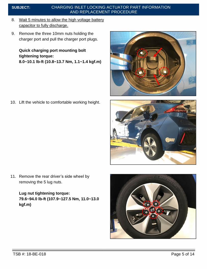
(AE PHEV)
SUBJECT: CHARGING INLET LOCKING ACTUATOR PART INFORMATION
AND REPLACEMENT PROCEDURE
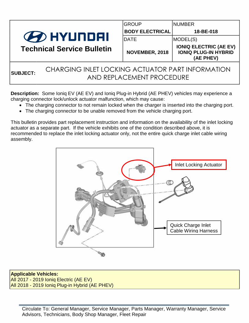
Description: Some Ioniq EV (AE EV) and Ioniq Plug-in Hybrid (AE PHEV) vehicles may experience a charging connector lock/unlock actuator malfunction, which may cause:
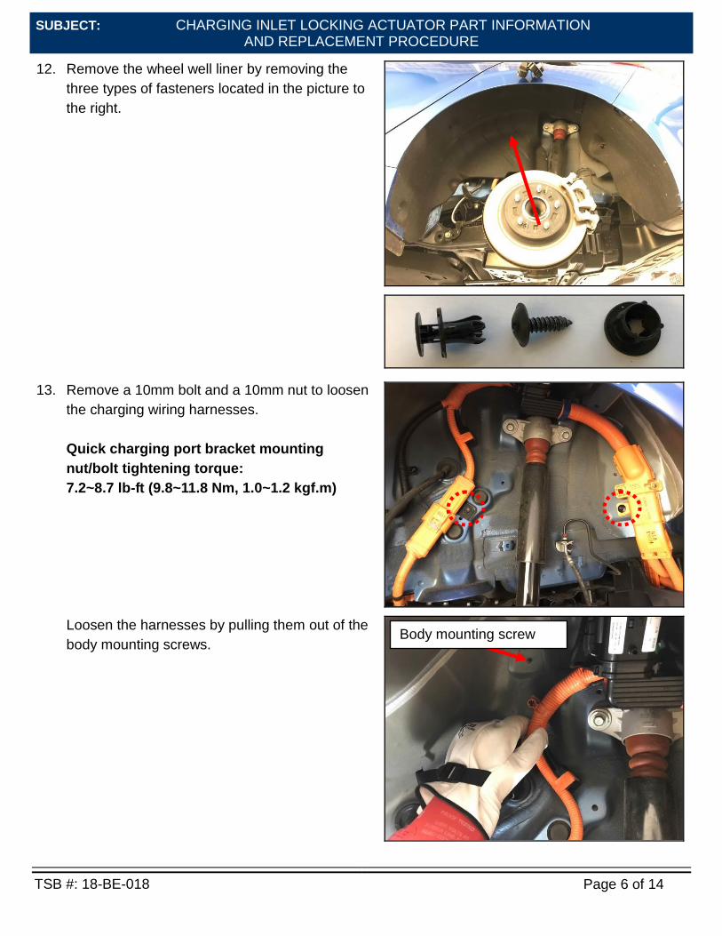
The charging connector to not remain locked when the charger is inserted into the charging port.
The charging connector to be unable removed from the vehicle charging port. This bulletin provides part replacement instruction and information on the availability of the inlet locking actuator as a separate part. If the vehicle exhibits one of the condition described above, it is recommended to replace the inlet locking actuator only, not the entire quick charge inlet cable wiring assembly.
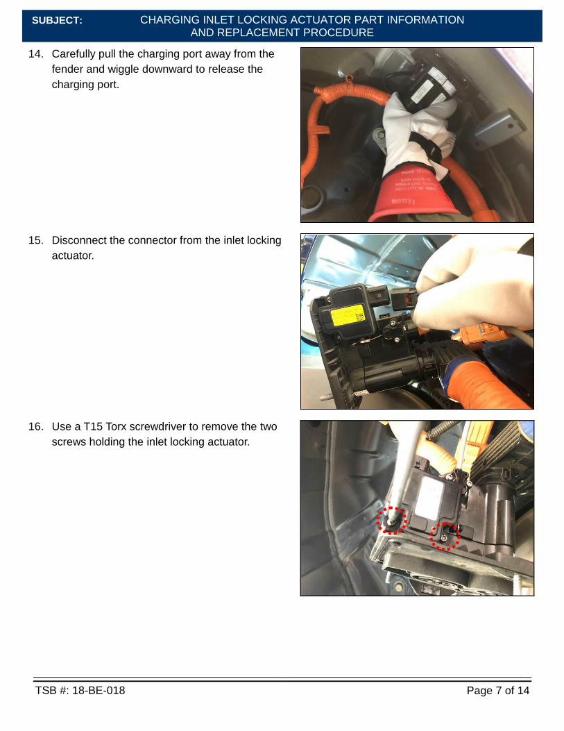
Applicable Vehicles: All 2017 - 2019 Ioniq Electric (AE EV) All 2018 - 2019 Ioniq Plug-in Hybrid (AE PHEV)
Inlet Locking Actuator
Quick Charge Inlet Cable Wiring Harness
CHARGING INLET LOCKING ACTUATOR PART INFORMATION AND REPLACEMENT PROCEDURE
TSB #: 18-BE-018 Page 2 of 14
SUBJECT:
Warranty Information:
MODEL OP. CODE OPERATION OP. TIME CAUSAL PART NATURE CAUSE
Ioniq Electric (AE EV)
91999R00 Inlet Locking
Actuator Replacement
Please see
WEBLTS for current LTS time.
For Causal P/N: Refer to the
Parts Information for the inlet locking
actuator P/N per applicable
model.
I14 ZZ3
Ioniq Plug-in Hybrid
(AE PHEV)
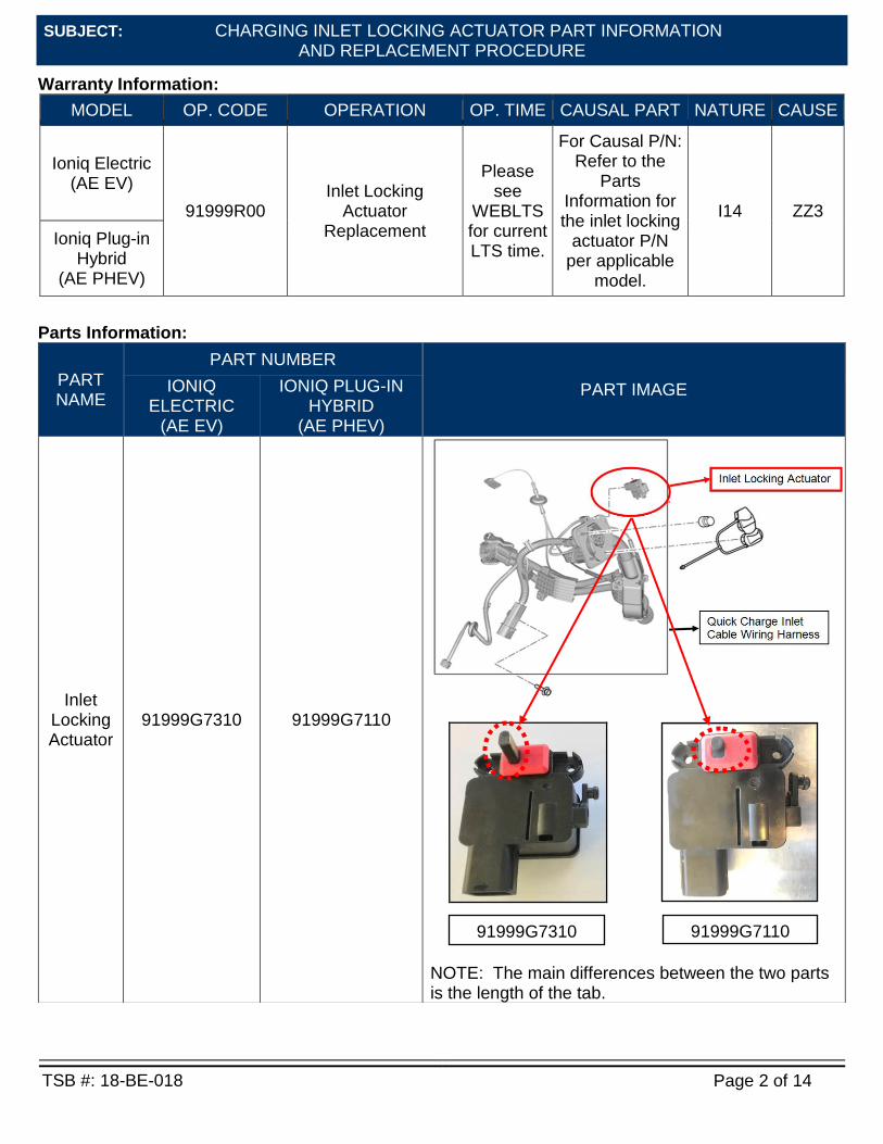
Parts Information:
PART NAME
PART NUMBER
PART IMAGE IONIQ ELECTRIC
(AE EV)
IONIQ PLUG-IN HYBRID
(AE PHEV)
Inlet Locking Actuator
91999G7310
91999G7110
NOTE: The main differences between the two parts is the length of the tab.
91999G7310
91999G7110
CHARGING INLET LOCKING ACTUATOR PART INFORMATION AND REPLACEMENT PROCEDURE
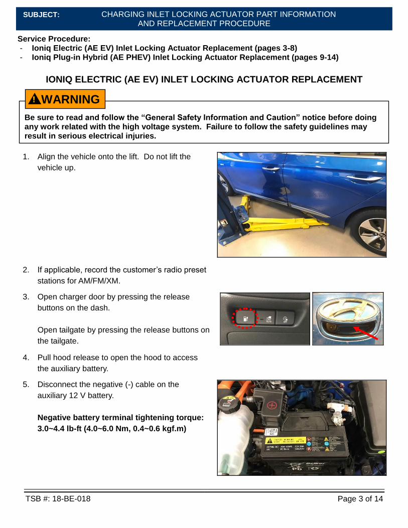
IONIQ ELECTRIC (AE EV) INLET LOCKING ACTUATOR REPLACEMENT
1. Align the vehicle onto the lift. Do not lift the
vehicle up.
2. If applicable, record the customer’s radio preset
stations for AM/FM/XM.
3. Open charger door by pressing the release
buttons on the dash.
Open tailgate by pressing the release buttons on
the tailgate.
4. Pull hood release to open the hood to access
the auxiliary battery.
5. Disconnect the negative (-) cable on the
auxiliary 12 V battery.
Negative battery terminal tightening torque:
3.0~4.4 lb-ft (4.0~6.0 Nm, 0.4~0.6 kgf.m)
Be sure to read and follow the “General Safety Information and Caution” notice before doing any work related with the high voltage system. Failure to follow the safety guidelines may result in serious electrical injuries.
WARNING !
CHARGING INLET LOCKING ACTUATOR PART INFORMATION AND REPLACEMENT PROCEDURE
TSB #: 18-BE-018 Page 4 of 14
SUBJECT:
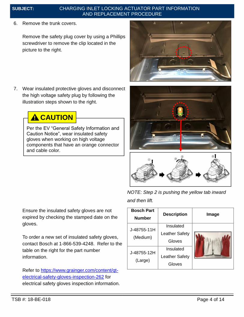
6. Remove the trunk covers.
Remove the safety plug cover by using a Phillips
screwdriver to remove the clip located in the
picture to the right.
7. Wear insulated protective gloves and disconnect
the high voltage safety plug by following the
illustration steps shown to the right.
NOTE: Step 2 is pushing the yellow tab inward
and then lift.
Ensure the insulated safety gloves are not
expired by checking the stamped date on the
gloves.
To order a new set of insulated safety gloves,
contact Bosch at 1-866-539-4248. Refer to the
table on the right for the part number
information.
Refer to https://www.grainger.com/content/qt-
electrical-safety-gloves-inspection-262 for
electrical safety gloves inspection information.
Bosch Part
Number Description Image
J-48755-11H
(Medium)
Insulated
Leather Safety
Gloves
J-48755-12H
(Large)
Insulated
Leather Safety
Gloves
Per the EV “General Safety Information and Caution Notice”, wear insulated safety gloves when working on high voltage components that have an orange connector and cable color.
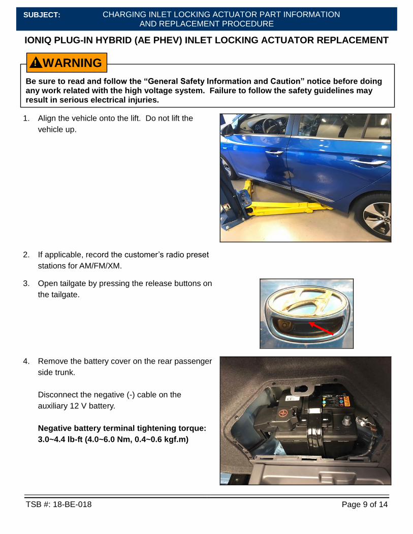
1. Align the vehicle onto the lift. Do not lift the
vehicle up.
2. If applicable, record the customer’s radio preset
stations for AM/FM/XM.
3. Open tailgate by pressing the release buttons on
the tailgate.
4. Remove the battery cover on the rear passenger
side trunk.
Disconnect the negative (-) cable on the
auxiliary 12 V battery.
Negative battery terminal tightening torque:
3.0~4.4 lb-ft (4.0~6.0 Nm, 0.4~0.6 kgf.m)
Be sure to read and follow the “General Safety Information and Caution” notice before doing any work related with the high voltage system. Failure to follow the safety guidelines may result in serious electrical injuries.
WARNING !
CHARGING INLET LOCKING ACTUATOR PART INFORMATION AND REPLACEMENT PROCEDURE
TSB #: 18-BE-018 Page 10 of 14
SUBJECT:
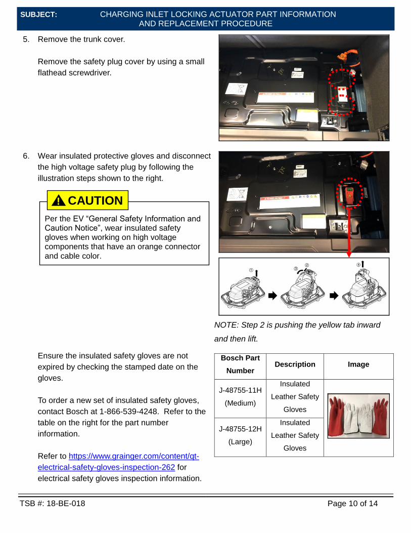
5. Remove the trunk cover.
Remove the safety plug cover by using a small
flathead screwdriver.
6. Wear insulated protective gloves and disconnect
the high voltage safety plug by following the
illustration steps shown to the right.
NOTE: Step 2 is pushing the yellow tab inward
and then lift.
Ensure the insulated safety gloves are not
expired by checking the stamped date on the
gloves.
To order a new set of insulated safety gloves,
contact Bosch at 1-866-539-4248. Refer to the
table on the right for the part number
information.
Refer to https://www.grainger.com/content/qt-
electrical-safety-gloves-inspection-262 for
electrical safety gloves inspection information.
Bosch Part
Number Description Image
J-48755-11H
(Medium)
Insulated
Leather Safety
Gloves
J-48755-12H
(Large)
Insulated
Leather Safety
Gloves
Per the EV “General Safety Information and Caution Notice”, wear insulated safety gloves when working on high voltage components that have an orange connector and cable color.