15
Body Electrical Model Outline Engine Chassis Body for Technician 1 Contents Click a Section Tab
| Date post: | 27-Dec-2015 |
| Category: |
Documents |
| Upload: | francis-lloyd |
| View: | 220 times |
| Download: | 1 times |

Body Electrical
Model Outline Engine Chassis Bodyfor Technician
1
ContentsClick a Section Tab

Body Electrical
Model Outline Engine Chassis Bodyfor Technician
2
K111 CVT
Body Electrical
Model Outline Engine Chassis Bodyfor Technician
3
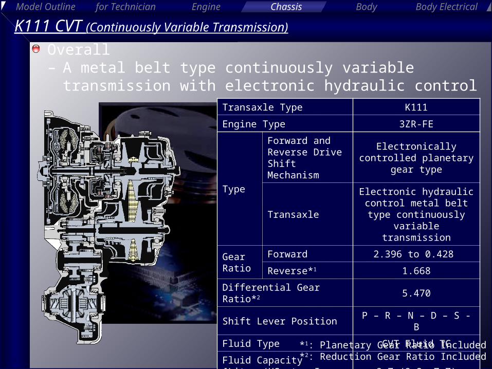
K111 CVT (Continuously Variable Transmission)
Overall– A metal belt type continuously variable transmission
with electronic hydraulic controlTransaxle Type K111
Engine Type 3ZR-FE
Type
Forward and Reverse Drive Shift Mechanism
Electronically controlled planetary gear type
Transaxle
Electronic hydraulic control metal belt type continuously variable
transmission
Gear Ratio
Forward 2.396 to 0.428
Reverse*1 1.668
Differential Gear Ratio*2 5.470
Shift Lever Position P – R – N – D – S - B
Fluid Type CVT Fluid TC
Fluid Capacity[Liter (US qts, Imp. qts)]
8.7 (9.2, 7.7)
*1: Planetary Gear Ratio Included*2: Reduction Gear Ratio Included

Body Electrical
Model Outline Engine Chassis Bodyfor Technician
4
K111 CVTFeatures of CVT– CVT perform speed ratio control using a pair of pulleys
Secondary Pulley
Primary Pulley
Metal Belt
Pulley Width = Large
Operation of CVT
High Speed RatioLow Speed Ratio
Engine Speed
Vehicle Speed
General AT
CVT(Shaded Region)
1st 2nd 3rd
4th
Speed Ratio
INPUT
OUTPUT
Pulley Width = Small
Pulley Width = Small
Pulley Width = Large

Body Electrical
Model Outline Engine Chassis Bodyfor Technician
5
K111 CVTFeatures of CVT– Driving near optimal fuel consumption is allowed
Engine Torque
Optimal Fuel Consumption
Specific Fuel Consumption
Map
Engine Speed
Area used when driving Enlargement of fuel cut area when deceleration
Vehicle Speed
ON
Enlarged Fuel Cut
AreaSpeed Ratio Control Area
for CVT1st 2nd
3rd
4thEngine Speed
Fuel Cut
OFF
: CVT: General AT: CVT: General AT

Body Electrical
Model Outline Engine Chassis Bodyfor Technician
6
K111 CVTFeatures of CVT– Engine speed in a high output range can be maintained
Engine Speed
Time
Engine Speed During Full Throttle Acceleration
Maximum Engine
Output Point
: CVT: General AT: CVT: General AT

Body Electrical
Model Outline Engine Chassis Bodyfor Technician
7
Effective Driving Force Area in CVT
K111 CVTFeatures of CVT– Smooth driving force characteristics
Driving Force
High
Vehicle SpeedHigh
Chart of Driving Force Characteristics
: CVT: General AT: CVT: General AT

Body Electrical
Model Outline Engine Chassis Bodyfor Technician
8
K111 CVTComponents
Torque Converter with Lock-up Clutch
Continuously Variable
Transmission and Metal Belt
Forward and Reverse Drive
Shift Mechanism
Oil Pump
Reduction Gear
Differential Gear
Parking Lock Mechanism
Secondary Pulley
Primary Pulley
Metal Belt

Body Electrical
Model Outline Engine Chassis Bodyfor Technician
9
K111 CVTComponents
Valve Body Unit(Hydraulic Control Unit)
CVT Fluid Warmer
Overflow Plug
3 Speed Sensors
Oil Pressure Sensor

Body Electrical
Model Outline Engine Chassis Bodyfor Technician
10
Reference (K111 CVT)
Components (K210 CVT)
K210 CVT
Secondary Pulley
Primary Pulley
Metal Belt
CVT Fluid
Warmer
Torque Converter with Lock-up Clutch
Forward and Reverse Drive
Shift Mechanism

Body Electrical
Model Outline Engine Chassis Bodyfor Technician
11
K111 CVTTorque Converter with Lock-up Clutch– Damper structure allowing lock-up from low speed
range
Pump Impeller
Stator
Turbine Runner
One-way Clutch
Lock-up Clutch
Damper Structure

Body Electrical
Model Outline Engine Chassis Bodyfor Technician
12
K111 CVTOil Pump– The oil pump is combined with the torque converter,
lubricates the parts and supplies operating pressure to the hydraulic control
Oil Pump

Body Electrical
Model Outline Engine Chassis Bodyfor Technician
13
K111 CVTGear Train– Consists of a planetary gear, continuously variable
transmission, reduction gear and differential gear
Planetary Gear Unit
Continuously Variable
Transmission
Reduction Gear
Final Gear
Input Shaft
Forward Clutch
Reverse Brake
Primary Pulley
Secondary Pulley
Metal Belt

Body Electrical
Model Outline Engine Chassis Bodyfor Technician
14
K111 CVTGear Train– Operation (D Position)
D position(Lowest Ratio)
D position(Highest Ratio)
ON
OFF
Pulley Width = Large
Pulley Width = Small
ON
OFF
Pulley Width = Small
Pulley Width = Large
Body Electrical
Model Outline Engine Chassis Bodyfor Technician
15
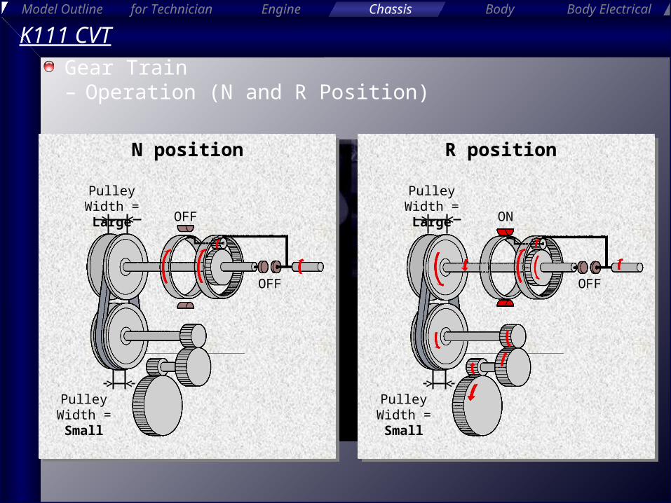
N position R position
K111 CVTGear Train– Operation (N and R Position)
OFF
OFF
Pulley Width = Large
Pulley Width = Small
OFF
ON
Pulley Width = Large
Pulley Width = Small


