BRM-1 BODY EXTERIOR, DOORS, ROOF & VEHICLE SECURITY C D E F G H I J L M SECTION BRM A B BRM N O P CONTENTS BODY REPAIR VEHICLE INFORMATION ............................ 2 BODY EXTERIOR PAINT COLOR .................... 2 Body Exterior Paint Color ...................................... 2 PRECAUTION .............................................. 3 REPAIRING HIGH STRENGTH STEEL ............. 3 High Strength Steel (HSS) ..................................... 3 Handling of Ultra High Strength Steel Plate Parts ...... 5 PREPARATION ........................................... 6 REPAIRING MATERIAL .................................... 6 Foam Repair ............................................................ 6 BODY COMPONENT PARTS ............................ 8 Underbody Component Parts ................................. 8 Body Component Parts .......................................... 10 REMOVAL AND INSTALLATION .............. 13 CORROSION PROTECTION ............................13 Description ............................................................. 13 Undercoating .......................................................... 13 Body Sealing .......................................................... 14 BODY CONSTRUCTION ...................................18 Body Construction .................................................. 18 Rear Fender Hemming Process ............................. 19 REPLACEMENT OPERATIONS .......................21 Description ............................................................. 21 Radiator Core Support ........................................... 23 Hoodledge ..............................................................23 Front Side Member (2WD) .....................................26 Front Side Member (AWD) .....................................29 Front Side Member (Partial Replacement) ..........32 Front Pillar ..............................................................33 Side Body ...............................................................35 Center Pillar ............................................................39 Outer Sill (Partial Replacement) .............................43 Outer Sill ................................................................44 Rear Fender ...........................................................49 Rear Fender Extension ...........................................52 Outer Rear Wheelhouse .........................................52 Rear Panel .............................................................58 Rear Floor Rear ....................................................58 Rear Side Member Extension .................................59 SERVICE DATA AND SPECIFICATIONS (SDS) ........................................................... 61 BODY ALIGNMENT .......................................... 61 Body Center Marks ...............................................61 Description ..............................................................62 Engine Compartment .............................................62 Underbody (2WD) ...................................................64 Underbody (AWD) ..................................................67 Passenger Compartment ........................................70 Rear Body ..............................................................72 LOCATION OF PLASTIC PARTS .................... 75 Precautions for Plastics ..........................................75 Location of Plastic Parts .........................................76 Revision: 2010 June 2011 M37/M56
Transcript
BODY EXTERIOR, DOORS, ROOF & VEHICLE SECURITY
C
D
E
SECTION BRMA
B
BODY REPAIR
F
G
H
I
J
L
M
RM
N
O
P
CONTENTS
B
VEHICLE INFORMATION ............................. 2
BODY EXTERIOR PAINT COLOR ..................... 2Body Exterior Paint Color .......................................2
REPAIRING HIGH STRENGTH STEEL .............. 3High Strength Steel (HSS) ......................................3Handling of Ultra High Strength Steel Plate Parts ......5
REPAIRING MATERIAL ..................................... 6Foam Repair .............................................................6
BODY COMPONENT PARTS ............................. 8Underbody Component Parts ..................................8Body Component Parts ...........................................10
BODY CONSTRUCTION ....................................18Body Construction ...................................................18Rear Fender Hemming Process ..............................19
REPLACEMENT OPERATIONS ........................21Description ..............................................................21Radiator Core Support ............................................23
Hoodledge ...............................................................23Front Side Member (2WD) ......................................26Front Side Member (AWD) ......................................29Front Side Member (Partial Replacement) ...........32Front Pillar ...............................................................33Side Body ................................................................35Center Pillar .............................................................39Outer Sill (Partial Replacement) ..............................43Outer Sill .................................................................44Rear Fender ............................................................49Rear Fender Extension ............................................52Outer Rear Wheelhouse ..........................................52Rear Panel ..............................................................58Rear Floor Rear .....................................................58Rear Side Member Extension ..................................59
SERVICE DATA AND SPECIFICATIONS (SDS) ............................................................61
BODY ALIGNMENT ..........................................61Body Center Marks ................................................61Description ...............................................................62Engine Compartment ..............................................62Underbody (2WD) ....................................................64Underbody (AWD) ...................................................67Passenger Compartment .........................................70Rear Body ...............................................................72
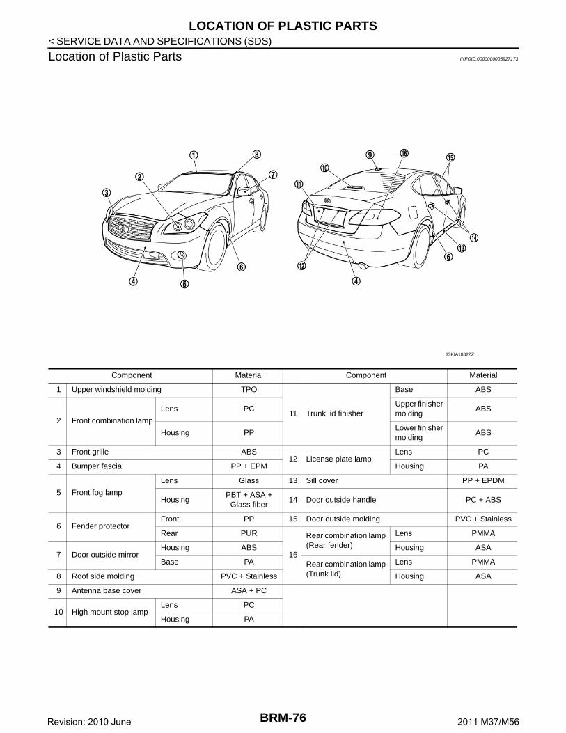
LOCATION OF PLASTIC PARTS ....................75Precautions for Plastics ...........................................75Location of Plastic Parts ..........................................76
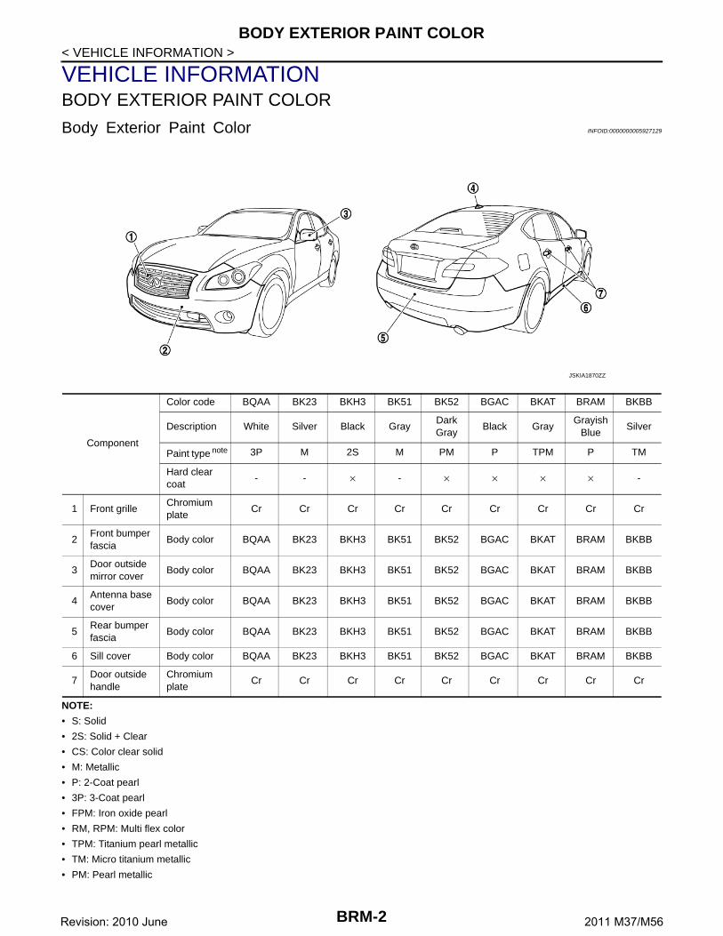
Body color BQAA BK23 BKH3 BK51 BK52 BGAC BKAT BRAM BKBB
3Door outside mirror cover
Body color BQAA BK23 BKH3 BK51 BK52 BGAC BKAT BRAM BKBB
4Antenna base cover
Body color BQAA BK23 BKH3 BK51 BK52 BGAC BKAT BRAM BKBB
5Rear bumper fascia
Body color BQAA BK23 BKH3 BK51 BK52 BGAC BKAT BRAM BKBB
6 Sill cover Body color BQAA BK23 BKH3 BK51 BK52 BGAC BKAT BRAM BKBB
7Door outside handle
Chromium plate
Cr Cr Cr Cr Cr Cr Cr Cr Cr
BRM-2Revision: 2010 June 2011 M37/M56
REPAIRING HIGH STRENGTH STEEL
C
D
E
F
G
H
I
J
L
M
A
B
RM
N
O
P
< PRECAUTION >
B
PRECAUTIONREPAIRING HIGH STRENGTH STEEL
High Strength Steel (HSS) INFOID:0000000005927130
High strength steel is used for body panels in order to reduce vehicle weight.Accordingly, precautions in repairing automotive bodies made of high strength steel are described below:
Read the following precautions when repairing HSS:1. Additional points to consider
Tensile strength Major applicable parts
440 - 780 MPa
• Hoodledge reinforcement• Upper front hoodledge• Front strut housing• Rear floor seat belt anchor reinforcement• Rear seat crossmember reinforcement assembly• 2nd and 3rd crossmember
(Front floor component part) • Inner sill• Center front floor• Lower dash• Lower dash crossmember assembly• Front side member assembly• Front side member closing plate assembly• Front side member outrigger assembly• Rear seat crossmember• Rear tie down hook• Rear side member assembly• Rear side member extension• Inner front roof side rail
(Side body assembly component part) • Outer front pillar reinforcement (Lower)
(Side body assembly component part)• Outer sill reinforcement• Center pillar reinforcement• Outer rear wheelhouse extension (Upper)• Outer rear wheelhouse extension (Lower rear)• Front roof rail• Rear roof rail• Other reinforcements
980 - 1350 MPa
• Front side member stiffener(Front floor component part)
• Front side member rear extension• Inner roof side rail (Front)
(Side body assembly component part)• Outer roof side rail
(Side body assembly component part)• Inner center pillar
(Side body assembly component part)• Outer front pillar reinforcement (Upper)
(Side body assembly component part)• Outer sill extension
(Outer sill reinforcement component part)• Center pillar reinforcement (Upper)• Center pillar seat belt reinforcement
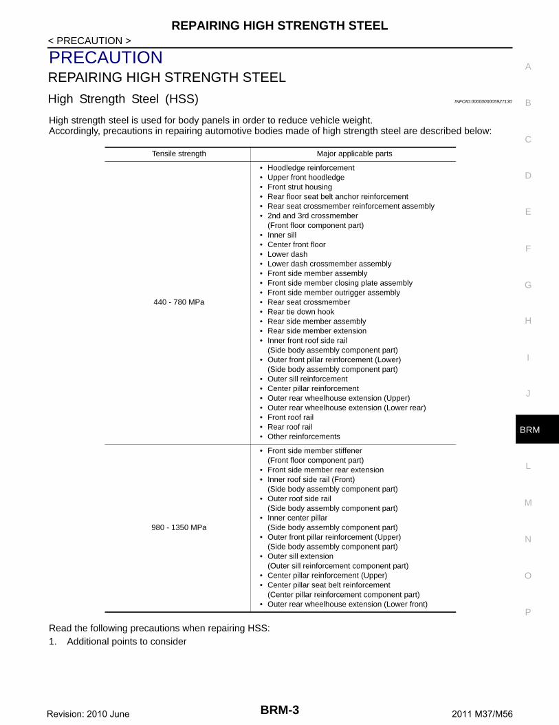
• The repair of reinforcements (such as side members) by heat-ing is not recommended, because it may weaken the compo-nent. When heating is unavoidable, never heat HSS partsabove 550°C (1,022°F).Verify heating temperature with a thermometer.(Crayon-type and other similar type thermometer are appropri-ate.)
• When straightening body panels, use caution in pulling any HSS panel. Because HSS is very strong,pulling may cause deformation in adjacent sections of the body. In this case, increase the number ofmeasuring points, and carefully pull the HSS panel.
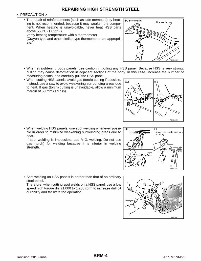
• When cutting HSS panels, avoid gas (torch) cutting if possible.Instead, use a saw to avoid weakening surrounding areas dueto heat. If gas (torch) cutting is unavoidable, allow a minimummargin of 50 mm (1.97 in).
• When welding HSS panels, use spot welding whenever possi-ble in order to minimize weakening surrounding areas due toheat.If spot welding is impossible, use MIG. welding. Do not usegas (torch) for welding because it is inferior in weldingstrength.
• Spot welding on HSS panels is harder than that of an ordinarysteel panel.Therefore, when cutting spot welds on a HSS panel, use a lowspeed high torque drill (1,000 to 1,200 rpm) to increase drill bitdurability and facilitate the operation.
PIIA0115E
PIIA0117E
PIIA0144E
PIIA0145E
BRM-4Revision: 2010 June 2011 M37/M56
REPAIRING HIGH STRENGTH STEEL
C
D
E
F
G
H
I
J
L
M
A
B
RM
N
O
P
< PRECAUTION >
B
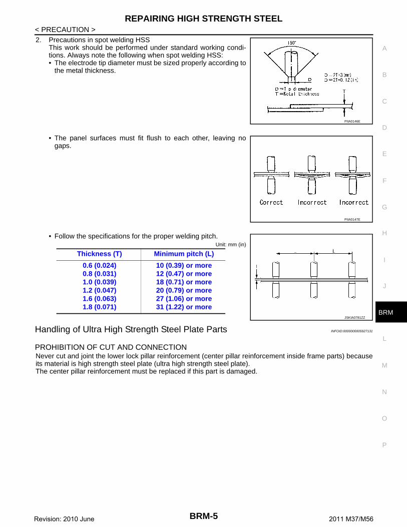
2. Precautions in spot welding HSSThis work should be performed under standard working condi-tions. Always note the following when spot welding HSS:• The electrode tip diameter must be sized properly according to
the metal thickness.
• The panel surfaces must fit flush to each other, leaving nogaps.
• Follow the specifications for the proper welding pitch.Unit: mm (in)
Handling of Ultra High Strength Steel Plate Parts INFOID:0000000005927131
PROHIBITION OF CUT AND CONNECTIONNever cut and joint the lower lock pillar reinforcement (center pillar reinforcement inside frame parts) becauseits material is high strength steel plate (ultra high strength steel plate). The center pillar reinforcement must be replaced if this part is damaged.
10 (0.39) or more12 (0.47) or more18 (0.71) or more20 (0.79) or more27 (1.06) or more31 (1.22) or more
JSKIA0781ZZ
BRM-5Revision: 2010 June 2011 M37/M56
REPAIRING MATERIAL
< PREPARATION >
PREPARATIONREPAIRING MATERIAL
Foam Repair INFOID:0000000005927132
During factory body assembly, foam insulators are installed in certain body panels and locations around thevehicle. Use the following procedure(s) to replace any factory-installed foam insulators.
URETHANE FOAM APPLICATIONSUse commercially available Urethane foam for sealant (foam material) repair of material used on vehicle.
Read instructions on product for fill procedures.
Example of foaming agent filling operation procedure
1. Fill procedures after installation of service part.a. Eliminate foam material remaining on vehicle side.b. Clean area after eliminating form insulator and foam material.c. Install service part.d. Insert nozzle into hole near fill area and fill foam material or fill enough to close gap with the service part.
2. Fill procedures before installation of service part.a. Eliminate foam material remaining on vehicle side.b. Clean area after eliminating foam insulator and foam material.c. Fill foam material on wheelhouse outer side.
<Urethane foam for foaming agent> 3M™ Automix™ Flexible Foam 08463 or equiva-lent
1. Urethane foam
A. Nozzle insert hole
: Vehicle front
JSKIA0129GB
BRM-6Revision: 2010 June 2011 M37/M56
REPAIRING MATERIAL
C
D
E
F
G
H
I
J
L
M
A
B
RM
N
O
P
< PREPARATION >
B
NOTE:Fill enough to close gap with service part while avoiding flangearea.
d. Install service part.NOTE:Refer to label for information on working times.
1. Urethane foam
A. Fill while avoiding flange area
: Vehicle front
JSKIA0130GB
BRM-7Revision: 2010 June 2011 M37/M56
BODY COMPONENT PARTS
< PREPARATION >
BODY COMPONENT PARTS
Underbody Component Parts INFOID:0000000005927133
: Both sided anti-corrosive precoated steel sections
: High strength steel (HSS) sections
: Both sided anti-corrosive steel and HSS sections
JSKIA1871ZZ
BRM-8Revision: 2010 June 2011 M37/M56
BODY COMPONENT PARTS
C
D
E
F
G
H
I
J
L
M
A
B
RM
N
O
P
< PREPARATION >
B
NOTE:
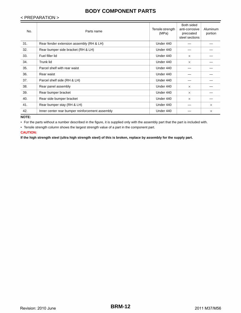
• For the parts without a number described in the figure, it is supplied only with the assembly part that the part is included with.
• Tensile strength column shows the largest strength value of a part in the component part.
CAUTION:
If the high strength steel (ultra high strength steel) of this is broken, replace by assembly for the supply part.
32. Rear bumper side bracket (RH & LH) Under 440 — —
33. Fuel filler lid Under 440 × —
34. Trunk lid Under 440 × —
35. Parcel shelf with rear waist Under 440 — —
36. Rear waist Under 440 — —
37. Parcel shelf side (RH & LH) Under 440 — —
38. Rear panel assembly Under 440 × —
39. Rear bumper bracket Under 440 × —
40. Rear side bumper bracket Under 440 × —
41. Rear bumper stay (RH & LH) Under 440 — ×
42. Inner center rear bumper reinforcement assembly Under 440 — ×
No. Parts nameTensile strength
(MPa)
Both sided anti-corrosive
precoated steel sections
Aluminum portion
BRM-12Revision: 2010 June 2011 M37/M56
CORROSION PROTECTION
C
D
E
F
G
H
I
J
L
M
A
B
RM
N
O
P
< REMOVAL AND INSTALLATION >
B
REMOVAL AND INSTALLATIONCORROSION PROTECTION
Description INFOID:0000000005927135
To provide improved corrosion prevention, the following anti-corrosive measures have been implemented inNISSAN production plants. When repairing or replacing body panels, it is necessary to use the same anti-cor-rosive measures.
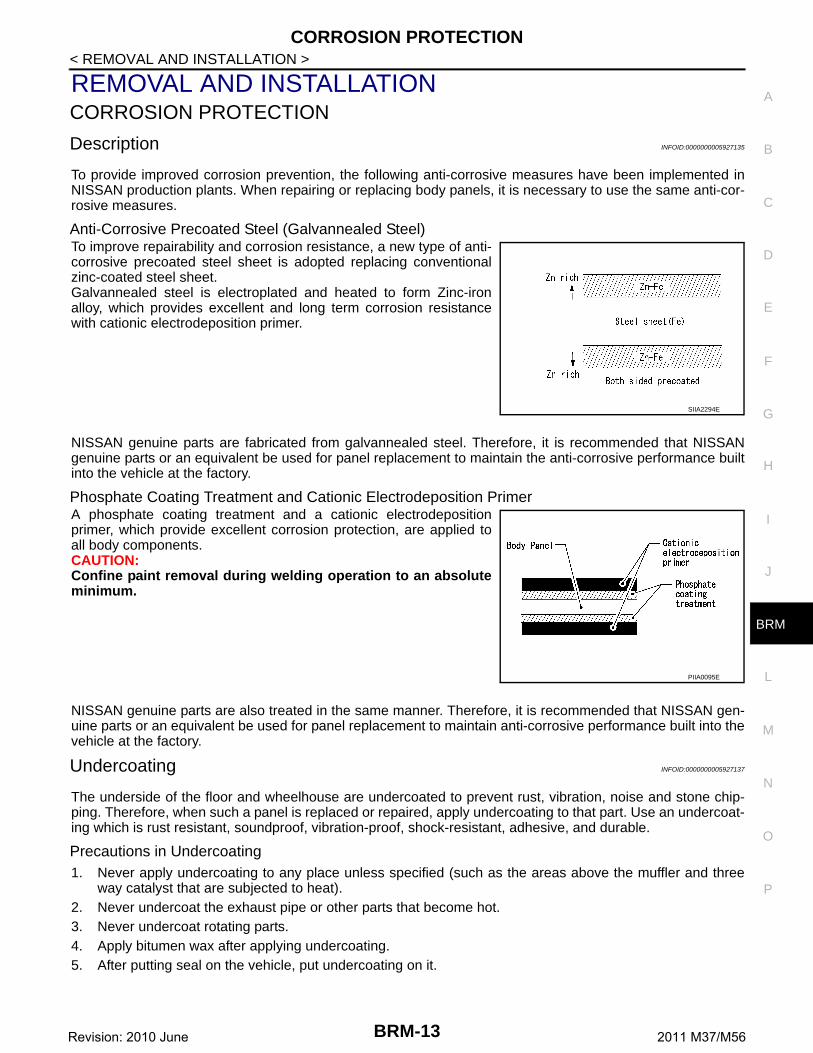
Anti-Corrosive Precoated Steel (Galvannealed Steel)To improve repairability and corrosion resistance, a new type of anti-corrosive precoated steel sheet is adopted replacing conventionalzinc-coated steel sheet.Galvannealed steel is electroplated and heated to form Zinc-ironalloy, which provides excellent and long term corrosion resistancewith cationic electrodeposition primer.
NISSAN genuine parts are fabricated from galvannealed steel. Therefore, it is recommended that NISSANgenuine parts or an equivalent be used for panel replacement to maintain the anti-corrosive performance builtinto the vehicle at the factory.
Phosphate Coating Treatment and Cationic Electrodeposition PrimerA phosphate coating treatment and a cationic electrodepositionprimer, which provide excellent corrosion protection, are applied toall body components.CAUTION:Confine paint removal during welding operation to an absoluteminimum.
NISSAN genuine parts are also treated in the same manner. Therefore, it is recommended that NISSAN gen-uine parts or an equivalent be used for panel replacement to maintain anti-corrosive performance built into thevehicle at the factory.
Undercoating INFOID:0000000005927137
The underside of the floor and wheelhouse are undercoated to prevent rust, vibration, noise and stone chip-ping. Therefore, when such a panel is replaced or repaired, apply undercoating to that part. Use an undercoat-ing which is rust resistant, soundproof, vibration-proof, shock-resistant, adhesive, and durable.
Precautions in Undercoating1. Never apply undercoating to any place unless specified (such as the areas above the muffler and three
way catalyst that are subjected to heat).2. Never undercoat the exhaust pipe or other parts that become hot.3. Never undercoat rotating parts.4. Apply bitumen wax after applying undercoating.5. After putting seal on the vehicle, put undercoating on it.
SIIA2294E
PIIA0095E
BRM-13Revision: 2010 June 2011 M37/M56
CORROSION PROTECTION
< REMOVAL AND INSTALLATION >
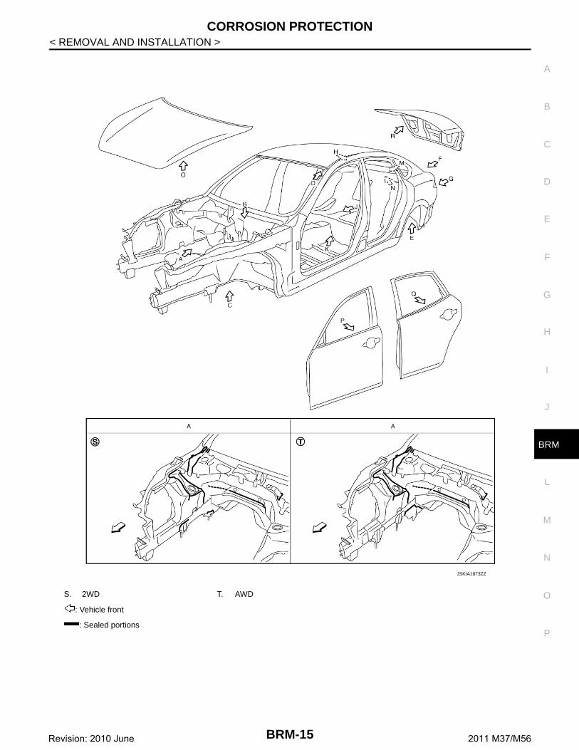
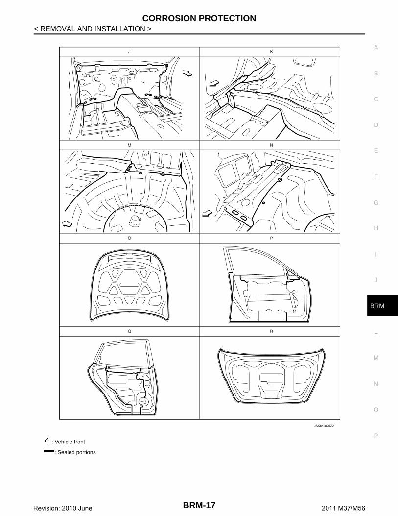
Body Sealing INFOID:0000000005927139
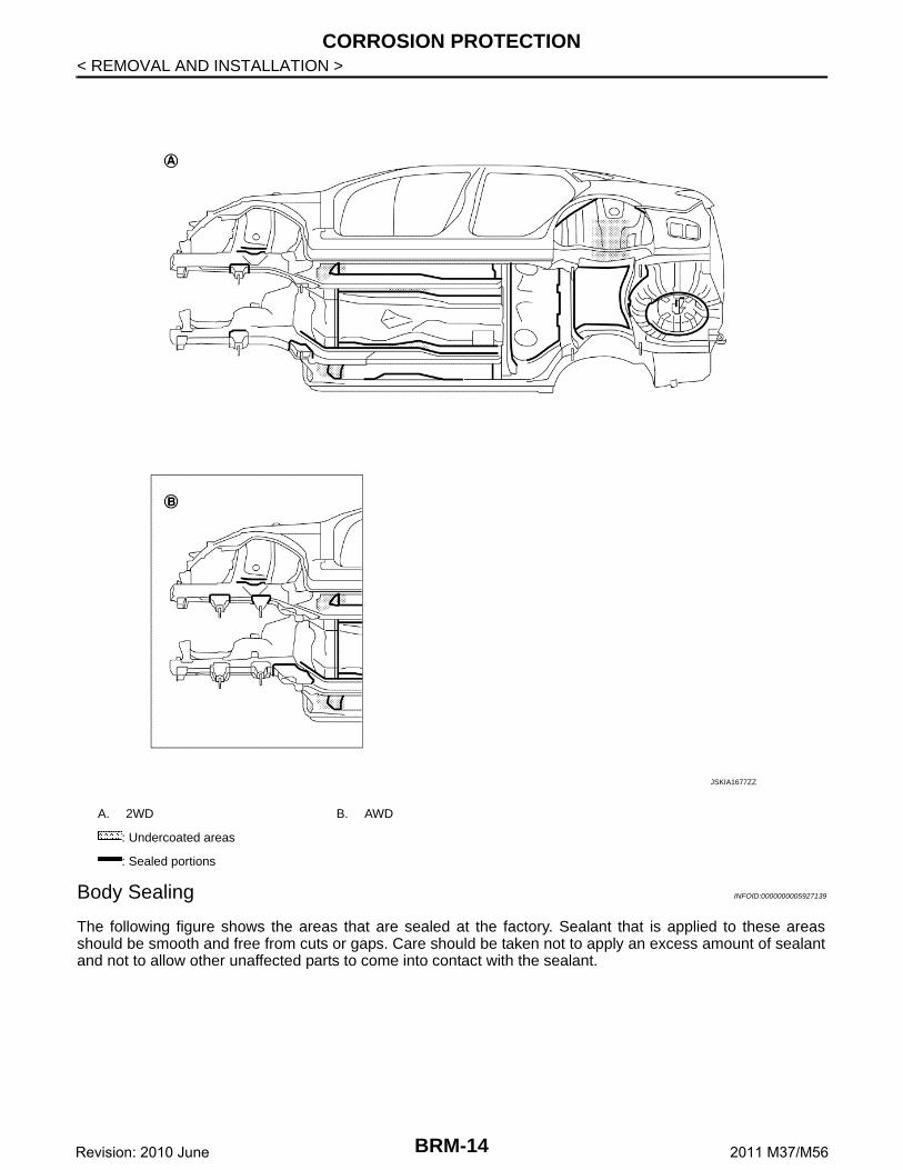
The following figure shows the areas that are sealed at the factory. Sealant that is applied to these areasshould be smooth and free from cuts or gaps. Care should be taken not to apply an excess amount of sealantand not to allow other unaffected parts to come into contact with the sealant.
A. 2WD B. AWD
: Undercoated areas
: Sealed portions
JSKIA1677ZZ
BRM-14Revision: 2010 June 2011 M37/M56
CORROSION PROTECTION
C
D
E
F
G
H
I
J
L
M
A
B
RM
N
O
P
< REMOVAL AND INSTALLATION >
B
S. 2WD T. AWD
: Vehicle front
: Sealed portions
JSKIA1873ZZ
BRM-15Revision: 2010 June 2011 M37/M56
CORROSION PROTECTION
< REMOVAL AND INSTALLATION >
S. 2WD T. AWD
: Vehicle front
: Sealed portions
JSKIA1874ZZ
BRM-16Revision: 2010 June 2011 M37/M56
CORROSION PROTECTION
C
D
E
F
G
H
I
J
L
M
A
B
RM
N
O
P
< REMOVAL AND INSTALLATION >
B
: Vehicle front
: Sealed portions
JSKIA1875ZZ
BRM-17Revision: 2010 June 2011 M37/M56
BODY CONSTRUCTION
< REMOVAL AND INSTALLATION >
BODY CONSTRUCTION
Body Construction INFOID:0000000005927140
1. Outer roof side rail 2. Outer side body 3. Outer front pillar reinforcement
4. Inner roof side rail 5. Outer front pillar bracket 6. Upper rear hoodledge
7. Upper dash 8. Hoodledge reinforcement gusset 9. Front pillar hinge brace
JSKIA1626ZZ
BRM-18Revision: 2010 June 2011 M37/M56
BODY CONSTRUCTION
C
D
E
F
G
H
I
J
L
M
A
B
RM
N
O
P
< REMOVAL AND INSTALLATION >
B
Rear Fender Hemming Process INFOID:0000000005927141
1. A wheel arch is to be installed and hemmed over the left and right outer wheel houses.2. In order to hem the wheel arch, it is necessary to repair any damaged or defaced parts around outer
wheel house.CAUTION:Ensure that the area that is to be glued around the outer wheelhouse is undamaged or defaced.
PROCEDURE OF THE HEMMING PROCESS• Peel off old bonding material on the surface of the outer wheel-
house and clean thoroughly.• Peel off a primer coat in the specified area where new adhesive is
to be applied on rear fender (the replacing part).• Apply new adhesive to both specified areas of the outer wheel-
house and rear fender.
• Attach rear fender to the body of the car, and weld the requiredpart except the hemming part.
• Bend the welded part starting from the center of the wheel archgradually with a hammer and a dolly. (Also hem the end of theflange.)
• Hemming with a hammer is conducted to an approximate angle of80 degrees.
10. Hoodledge reinforcement 11. Weld nut 12. Upper hinge plate
13. Lower dash crossmember 14. Front pillar bracket 15. Lower hinge plate
16. Lower front pillar gusset 17. Center sill reinforcement 18. Inner sill
19. Lower dash 20. Front side member outrigger 21. Outer front sill brace
22. Outer sill extension 23. 2nd crossmember 24. Front floor
25. Outer sill reinforcement 26. Inner center pillar 27. Center pillar seat belt reinforcement
28. Inner center pillar reinforcement 29. Center pillar reinforcement 30. Seat belt anchor
<Adhesive> 3M™ Automix™ Panel Bonding Adhe-sive 08115 or equivalent
JSKIA0136GB
SIIA2245E
BRM-19Revision: 2010 June 2011 M37/M56
BODY CONSTRUCTION
< REMOVAL AND INSTALLATION >• Starting from the center, hem the wheel arch gradually, using slight
back and forth motion with a hemming tool.
• Seal up the area around the hemmed end of the flange.
SIIA2246E
JSKIA0137GB
BRM-20Revision: 2010 June 2011 M37/M56
REPLACEMENT OPERATIONS
C
D
E
F
G
H
I
J
L
M
A
B
RM
N
O
P
< REMOVAL AND INSTALLATION >
B
REPLACEMENT OPERATIONS
Description INFOID:0000000005927142
• This section is prepared for technicians who have attained a high level of skill and experience in repairingcollision-damaged vehicles and also use modern service tools and equipment. Persons unfamiliar with bodyrepair techniques should not attempt to repair collision-damaged vehicles by using this section.
• Technicians are also encouraged to read the Body Repair Manual (Fundamentals) in order to ensure that theoriginal functions and quality of the vehicle are maintained. The Body Repair Manual (Fundamentals) con-tains additional information, including cautions and warnings, that are not including in this manual. Techni-cians should refer to both manuals to ensure proper repair.
• Please note that this information is prepared for worldwide usage, and as such, certain procedures might notapply in some regions or countries.
The symbols used in this section for welding operations are shown below.
Symbol marks Description
2-spot welds
3-spot welds
MIG plug weldFor 3 panels plug weld method
MIG seam weld / Point weld
JSKIA0049ZZ
JSKIA0053ZZ
JSKIA0050ZZ
JSKIA0051ZZ
JSKIA0054ZZ
JSKIA0055ZZ
JSKIA0052ZZ JSKIA0056ZZ
BRM-21Revision: 2010 June 2011 M37/M56
REPLACEMENT OPERATIONS
< REMOVAL AND INSTALLATION >• Front pillar butt joint can be determined anywhere within shaded
area as shown in the figure. The best location for the butt joint is atposition A due to the construction of the vehicle.
• Determine cutting position and record distance from the locatingindent. Use this distance when cutting the service part. Cut outerfront pillar over 60 mm (2.36 in) above the inner front pillar cutposition.
• Prepare a cutting jig to make outer pillar easier to cut. Also, this willpermit the service part to be accurately cut at the joint position.
• An example of cutting operation using a cutting jig is as per the fol-lowing.
1. Mark cutting lines.A: Cut position of outer pillarB: Cut position of inner pillar
2. Align cutting line with notch on jig. Clamp jig to pillar.3. Cut outer pillar along groove of jig (at position A).4. Remove jig and cut remaining portions.5. Cut inner pillar at position B in same manner.
PIIA0150E
JSKIA0104GB
JSKIA0105GB
PIIA0153E
BRM-22Revision: 2010 June 2011 M37/M56
REPLACEMENT OPERATIONS
C
D
E
F
G
H
I
J
L
M
A
B
RM
N
O
P
< REMOVAL AND INSTALLATION >
B
Radiator Core Support INFOID:0000000005927143
Hoodledge INFOID:0000000005927144
Work after radiator core support is removed.
: Vehicle front
Replacement parts
Radiator core support assembly (LH) Front side member connector as-sembly (LH)
JSKIA1628ZZ
BRM-23Revision: 2010 June 2011 M37/M56
REPLACEMENT OPERATIONS
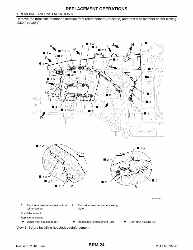
< REMOVAL AND INSTALLATION >Remove the front side member extension front reinforcement (reusable) and front side member center closingplate (reusable).
View B: Before installing hoodledge reinforcement
1. Front side member extension front reinforcement
2. Front side member center closing plate
: Vehicle front
Replacement parts
Upper front hoodledge (LH) Hoodledge reinforcement (LH) Front strut housing (LH)
JSKIA1629ZZ
BRM-24Revision: 2010 June 2011 M37/M56
REPLACEMENT OPERATIONS
C
D
E
F
G
H
I
J
L
M
A
B
RM
N
O
P
< REMOVAL AND INSTALLATION >
B
Unit: mm (in)
: Vehicle front
: Weld the parts onto the back of the component part.
JSKIA1630GB
BRM-25Revision: 2010 June 2011 M37/M56
REPLACEMENT OPERATIONS
< REMOVAL AND INSTALLATION >
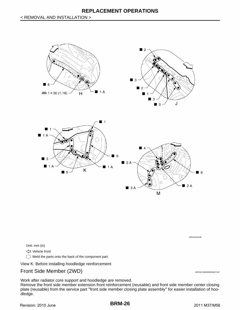
View K: Before installing hoodledge reinforcement
Front Side Member (2WD) INFOID:0000000005927147
Work after radiator core support and hoodledge are removed.Remove the front side member extension front reinforcement (reusable) and front side member center closingplate (reusable) from the service part ″front side member closing plate assembly″ for easier installation of hoo-dledge.
Unit: mm (in)
: Vehicle front
: Weld the parts onto the back of the component part.
JSKIA1631GB
BRM-26Revision: 2010 June 2011 M37/M56
REPLACEMENT OPERATIONS
C
D
E
F
G
H
I
J
L
M
A
B
RM
N
O
P
< REMOVAL AND INSTALLATION >
B
Unit: mm (in)
: Vehicle front: Weld the parts onto the back of the component part.
Replacement parts
Front side member assembly (LH) Front side member closing plate as-sembly (LH)
Front side member outrigger assem-bly (LH)
JSKIA1632GB
BRM-27Revision: 2010 June 2011 M37/M56
REPLACEMENT OPERATIONS
< REMOVAL AND INSTALLATION >
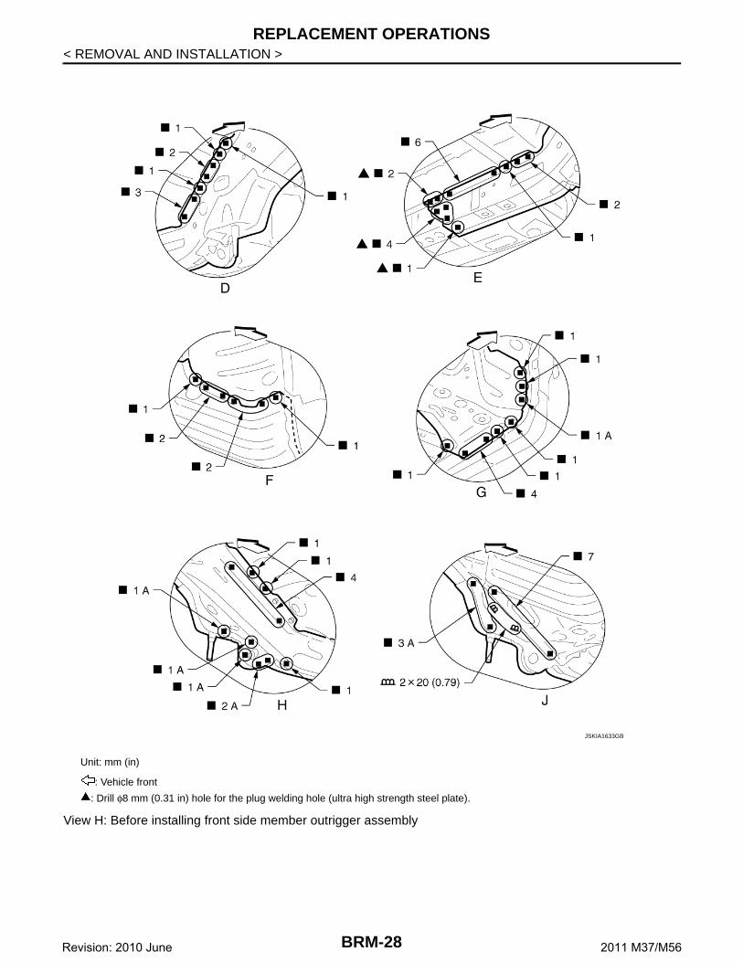
View H: Before installing front side member outrigger assembly
Unit: mm (in)
: Vehicle front
: Drill φ8 mm (0.31 in) hole for the plug welding hole (ultra high strength steel plate).
JSKIA1633GB
BRM-28Revision: 2010 June 2011 M37/M56
REPLACEMENT OPERATIONS
C
D
E
F
G
H
I
J
L
M
A
B
RM
N
O
P
< REMOVAL AND INSTALLATION >
B
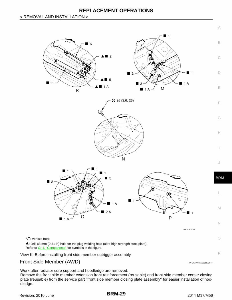
View K: Before installing front side member outrigger assembly
Front Side Member (AWD) INFOID:0000000005931544
Work after radiator core support and hoodledge are removed.Remove the front side member extension front reinforcement (reusable) and front side member center closingplate (reusable) from the service part ″front side member closing plate assembly″ for easier installation of hoo-dledge.
: Vehicle front
: Drill φ8 mm (0.31 in) hole for the plug welding hole (ultra high strength steel plate).Refer to GI-4, "Components" for symbols in the figure.
JSKIA1634GB
BRM-29Revision: 2010 June 2011 M37/M56
REPLACEMENT OPERATIONS
< REMOVAL AND INSTALLATION >
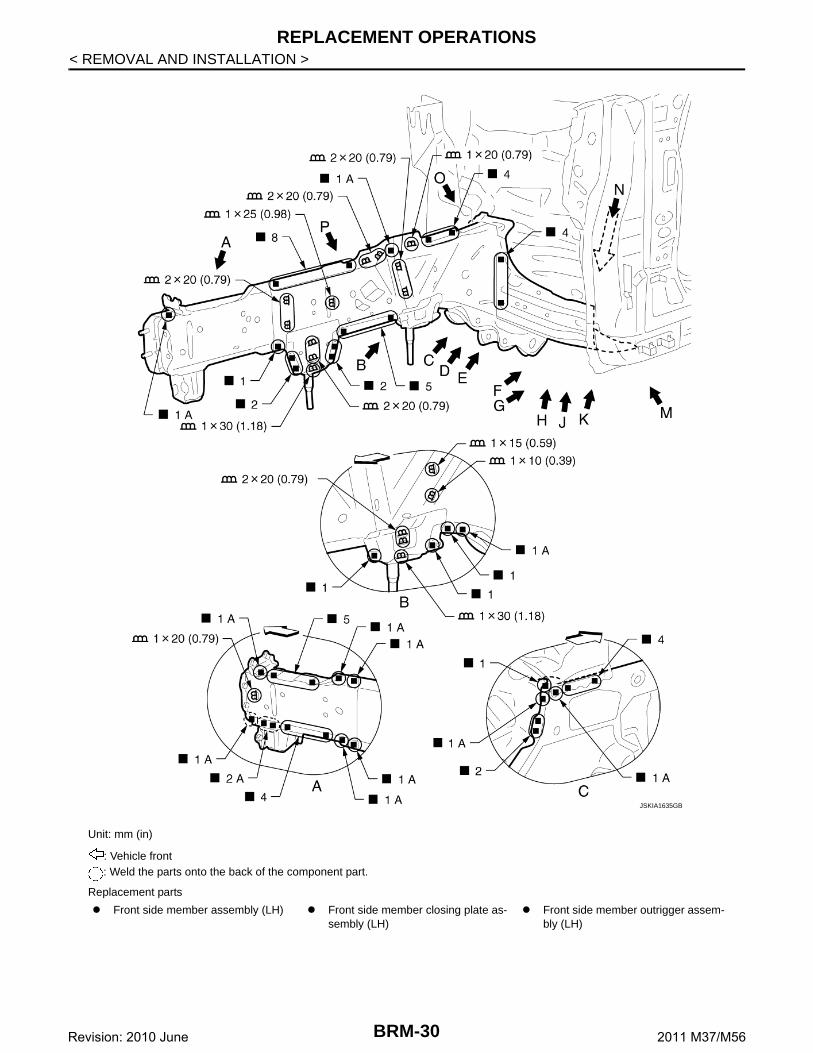
Unit: mm (in)
: Vehicle front: Weld the parts onto the back of the component part.
Replacement parts
Front side member assembly (LH) Front side member closing plate as-sembly (LH)
Front side member outrigger assem-bly (LH)
JSKIA1635GB
BRM-30Revision: 2010 June 2011 M37/M56
REPLACEMENT OPERATIONS
C
D
E
F
G
H
I
J
L
M
A
B
RM
N
O
P
< REMOVAL AND INSTALLATION >
B
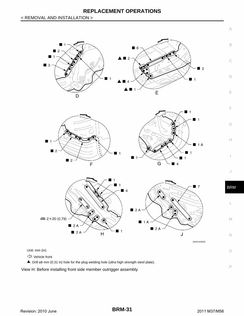
View H: Before installing front side member outrigger assembly
Unit: mm (in)
: Vehicle front
: Drill φ8 mm (0.31 in) hole for the plug welding hole (ultra high strength steel plate).
JSKIA1636GB
BRM-31Revision: 2010 June 2011 M37/M56
REPLACEMENT OPERATIONS
< REMOVAL AND INSTALLATION >
View K: Before installing front side member outrigger assembly
Front Side Member (Partial Replacement) INFOID:0000000005927148
Work after radiator core support is removed.
: Vehicle front
: Drill φ8 mm (0.31 in) hole for the plug welding hole (ultra high strength steel plate).Refer to GI-4, "Components" for symbols in the figure.
JSKIA1637GB
BRM-32Revision: 2010 June 2011 M37/M56
REPLACEMENT OPERATIONS
C
D
E
F
G
H
I
J
L
M
A
B
RM
N
O
P
< REMOVAL AND INSTALLATION >
B
Front Pillar INFOID:0000000005927149
Work after hoodledge reinforcement and roof are removed.
Unit: mm (in)
: Vehicle front
Replacement parts
Front side member front extension (LH)
Front side member front closing plate (LH)
JSKIA1638GB
BRM-33Revision: 2010 June 2011 M37/M56
REPLACEMENT OPERATIONS
< REMOVAL AND INSTALLATION >
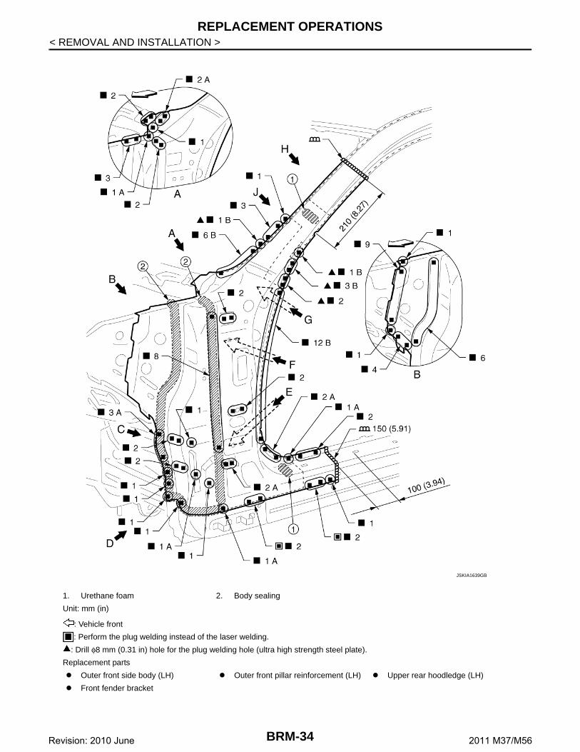
1. Urethane foam 2. Body sealing
Unit: mm (in)
: Vehicle front
: Perform the plug welding instead of the laser welding.
: Drill φ8 mm (0.31 in) hole for the plug welding hole (ultra high strength steel plate).
Replacement parts
Outer front side body (LH) Outer front pillar reinforcement (LH) Upper rear hoodledge (LH)
Front fender bracket
JSKIA1639GB
BRM-34Revision: 2010 June 2011 M37/M56
REPLACEMENT OPERATIONS
C
D
E
F
G
H
I
J
L
M
A
B
RM
N
O
P
< REMOVAL AND INSTALLATION >
B
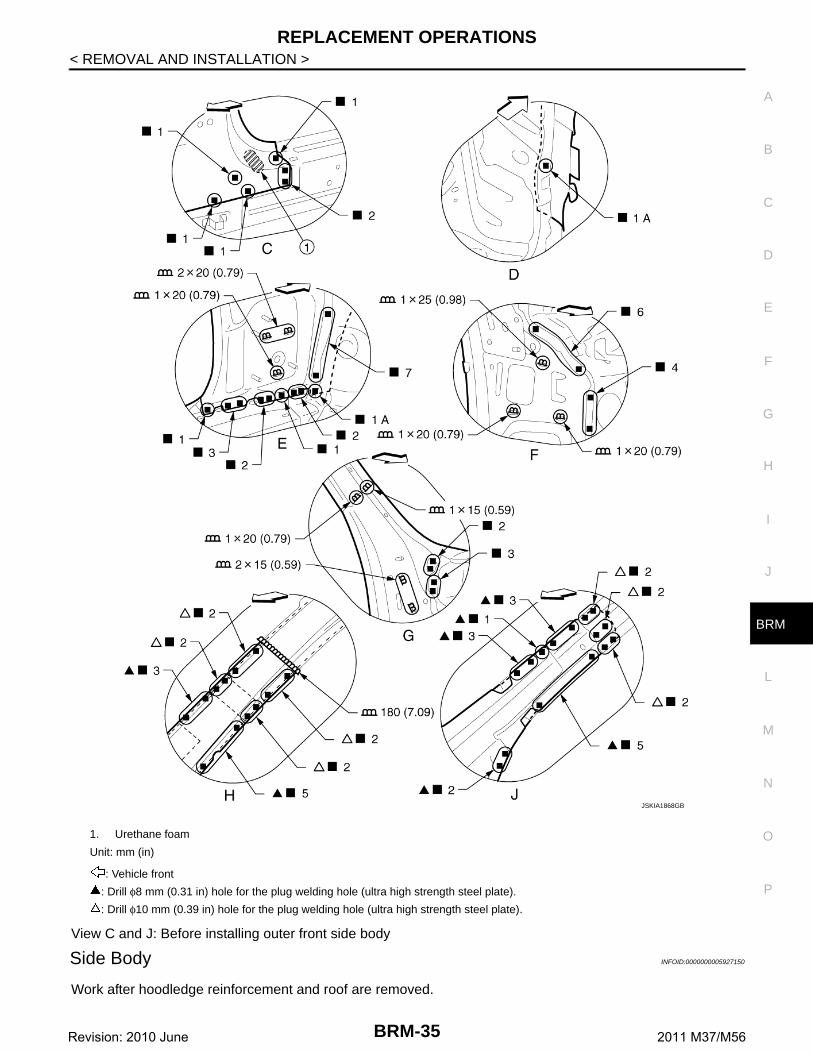
View C and J: Before installing outer front side body
Side Body INFOID:0000000005927150
Work after hoodledge reinforcement and roof are removed.
1. Urethane foam
Unit: mm (in)
: Vehicle front
: Drill φ8 mm (0.31 in) hole for the plug welding hole (ultra high strength steel plate).
: Drill φ10 mm (0.39 in) hole for the plug welding hole (ultra high strength steel plate).
JSKIA1868GB
BRM-35Revision: 2010 June 2011 M37/M56
REPLACEMENT OPERATIONS
< REMOVAL AND INSTALLATION >
: Vehicle front
: Drill φ8 mm (0.31 in) hole for the plug welding hole (ultra high strength steel plate).
: Weld the parts onto the back of the component part.
Replacement parts
Side body assembly (LH) Upper rear hoodledge (LH)
JSKIA1641ZZ
BRM-36Revision: 2010 June 2011 M37/M56
REPLACEMENT OPERATIONS
C
D
E
F
G
H
I
J
L
M
A
B
RM
N
O
P
< REMOVAL AND INSTALLATION >
B
Unit: mm (in)
: Vehicle front
: Drill φ8 mm (0.31 in) hole for the plug welding hole (ultra high strength steel plate).
: Weld the parts onto the back of the component part.Refer to GI-4, "Components" for symbols in the figure.
JSKIA1642GB
BRM-37Revision: 2010 June 2011 M37/M56
REPLACEMENT OPERATIONS
< REMOVAL AND INSTALLATION >
View M: Before installing side body assemblyView N: Side body assembly (replacement parts)
1. Urethane foam
Unit: mm (in)
: Vehicle front
: Drill φ8 mm (0.31 in) hole for the plug welding hole (ultra high strength steel plate).
: Weld the parts onto the back of the component part.Refer to GI-4, "Components" for symbols in the figure.
JSKIA1643GB
BRM-38Revision: 2010 June 2011 M37/M56
REPLACEMENT OPERATIONS
C
D
E
F
G
H
I
J
L
M
A
B
RM
N
O
P
< REMOVAL AND INSTALLATION >
B
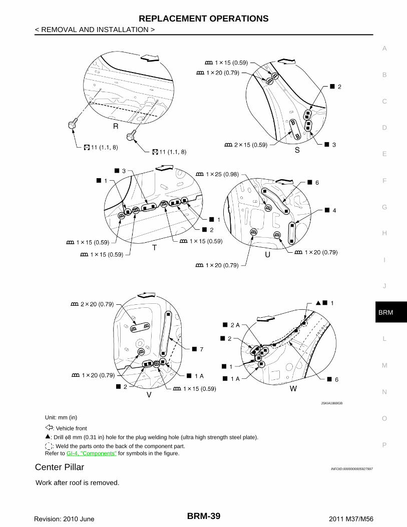
Center Pillar INFOID:0000000005927997
Work after roof is removed.
Unit: mm (in)
: Vehicle front
: Drill φ8 mm (0.31 in) hole for the plug welding hole (ultra high strength steel plate).
: Weld the parts onto the back of the component part.Refer to GI-4, "Components" for symbols in the figure.
JSKIA1869GB
BRM-39Revision: 2010 June 2011 M37/M56
REPLACEMENT OPERATIONS
< REMOVAL AND INSTALLATION >
1. Urethane foam
Unit: mm (in)
: Vehicle front
: Drill φ8 mm (0.31 in) hole for the plug welding hole (ultra high strength steel plate).
: Drill φ10 mm (0.39 in) hole for the plug welding hole (ultra high strength steel plate).
Replacement parts
Outer front side body (LH) Center pillar reinforcement (LH) Inner center pillar (LH)
JSKIA1645GB
BRM-40Revision: 2010 June 2011 M37/M56
REPLACEMENT OPERATIONS
C
D
E
F
G
H
I
J
L
M
A
B
RM
N
O
P
< REMOVAL AND INSTALLATION >
B
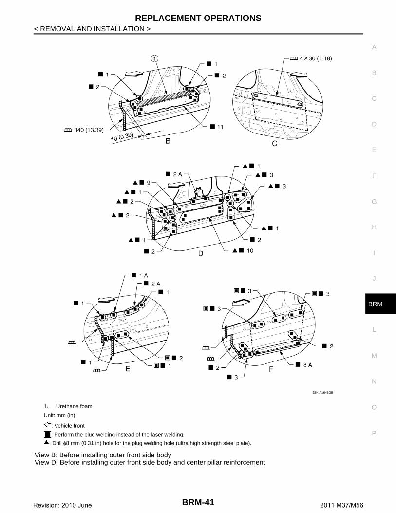
View B: Before installing outer front side bodyView D: Before installing outer front side body and center pillar reinforcement
1. Urethane foam
Unit: mm (in)
: Vehicle front
: Perform the plug welding instead of the laser welding.
: Drill φ8 mm (0.31 in) hole for the plug welding hole (ultra high strength steel plate).
JSKIA1646GB
BRM-41Revision: 2010 June 2011 M37/M56
REPLACEMENT OPERATIONS
< REMOVAL AND INSTALLATION >
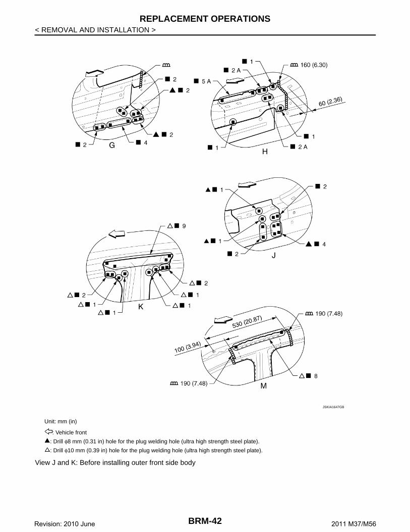
View J and K: Before installing outer front side body
Unit: mm (in)
: Vehicle front
: Drill φ8 mm (0.31 in) hole for the plug welding hole (ultra high strength steel plate).
: Drill φ10 mm (0.39 in) hole for the plug welding hole (ultra high strength steel plate).
: Perform the plug welding instead of the laser welding.
: Drill φ8 mm (0.31 in) hole for the plug welding hole (ultra high strength steel plate).
Replacement parts
Outer sill (LH) Outer sill reinforcement (LH)
JSKIA1648GB
BRM-43Revision: 2010 June 2011 M37/M56
REPLACEMENT OPERATIONS
< REMOVAL AND INSTALLATION >
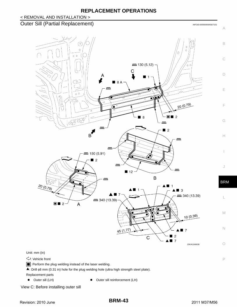
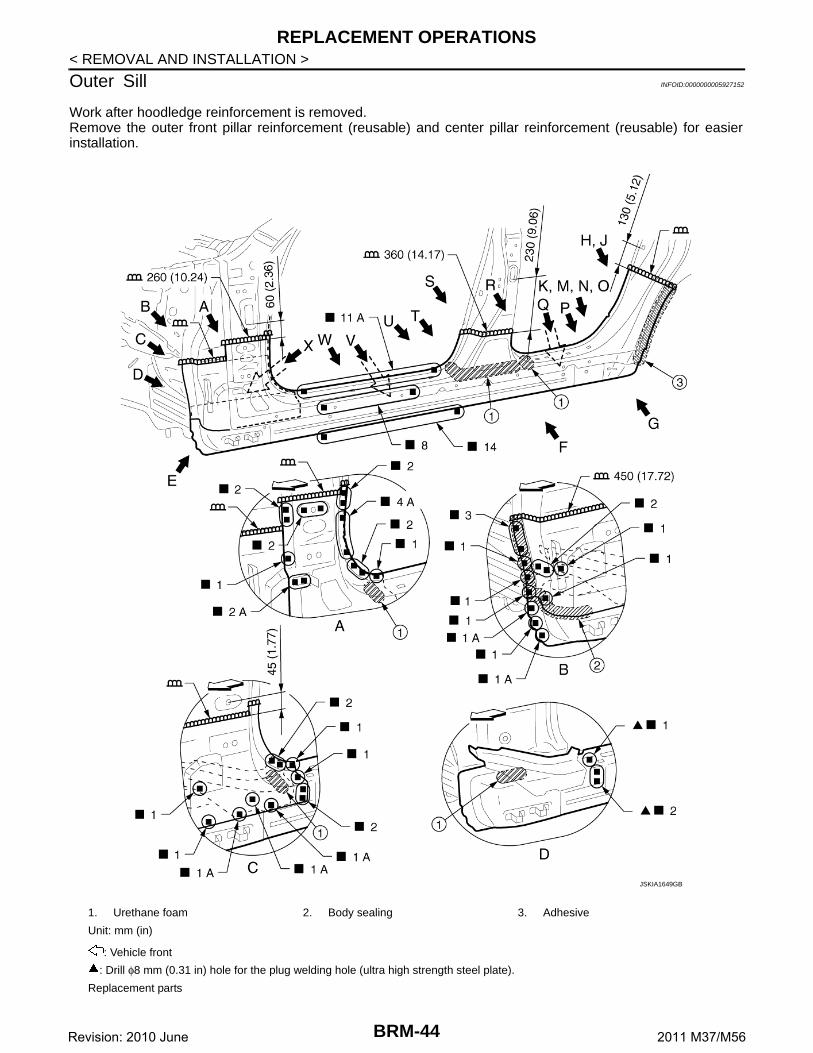
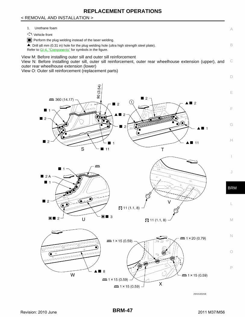
Outer Sill INFOID:0000000005927152
Work after hoodledge reinforcement is removed.Remove the outer front pillar reinforcement (reusable) and center pillar reinforcement (reusable) for easierinstallation.
1. Urethane foam 2. Body sealing 3. Adhesive
Unit: mm (in)
: Vehicle front
: Drill φ8 mm (0.31 in) hole for the plug welding hole (ultra high strength steel plate).
Replacement parts
JSKIA1649GB
BRM-44Revision: 2010 June 2011 M37/M56
REPLACEMENT OPERATIONS
C
D
E
F
G
H
I
J
L
M
A
B
RM
N
O
P
< REMOVAL AND INSTALLATION >
B
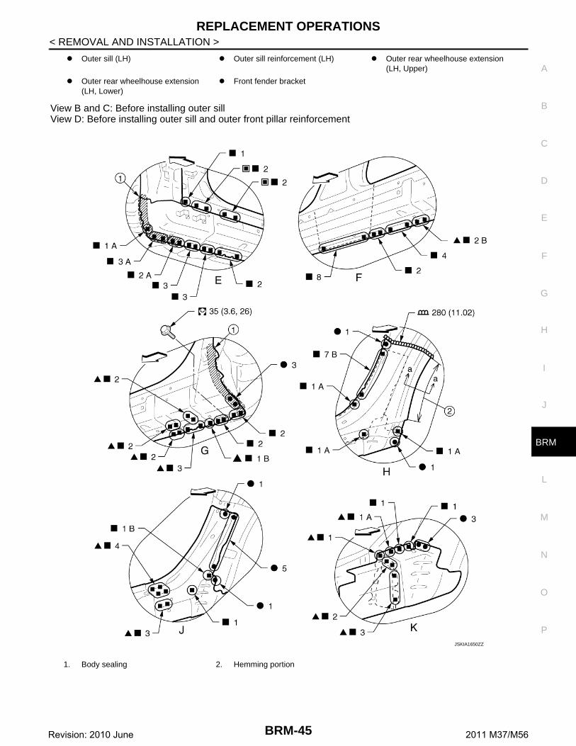
View B and C: Before installing outer sillView D: Before installing outer sill and outer front pillar reinforcement
: Drill φ8 mm (0.31 in) hole for the plug welding hole (ultra high strength steel plate).
: Weld the parts onto the back of the component part.
Replacement parts
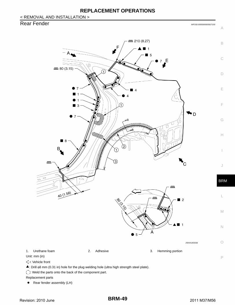
Rear fender assembly (LH)
JSKIA1653GB
BRM-49Revision: 2010 June 2011 M37/M56
REPLACEMENT OPERATIONS
< REMOVAL AND INSTALLATION >
View G: Right side rear fender
POINT
1. Body sealing 2. Adhesive
Unit: mm (in)
: Vehicle front
: Weld the parts onto the back of the component part.
JSKIA1654GB
BRM-50Revision: 2010 June 2011 M37/M56
REPLACEMENT OPERATIONS
C
D
E
F
G
H
I
J
L
M
A
B
RM
N
O
P
< REMOVAL AND INSTALLATION >
B
• Perform the hemming to the flange of wheelarch after applying theadhesive.
• Apply the sealing to the flange end.• Refer to BRM-19, "Rear Fender Hemming Process".
1. Outer rear wheelhouse2. Rear fender3. Adhesive
4. SealantJSKIA0204GB
BRM-51Revision: 2010 June 2011 M37/M56
REPLACEMENT OPERATIONS
< REMOVAL AND INSTALLATION >
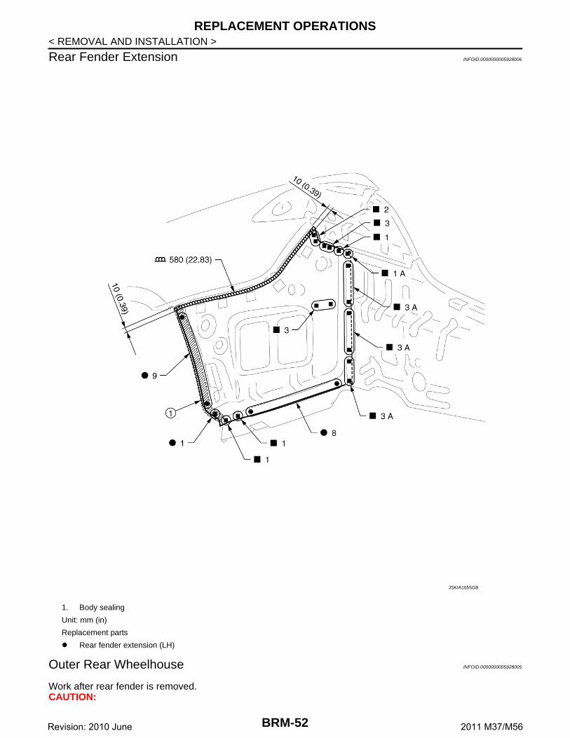
Rear Fender Extension INFOID:0000000005928006
Outer Rear Wheelhouse INFOID:0000000005928005
Work after rear fender is removed.CAUTION:
1. Body sealing
Unit: mm (in)
Replacement parts
Rear fender extension (LH)
JSKIA1655GB
BRM-52Revision: 2010 June 2011 M37/M56
REPLACEMENT OPERATIONS
C
D
E
F
G
H
I
J
L
M
A
B
RM
N
O
P
< REMOVAL AND INSTALLATION >
B
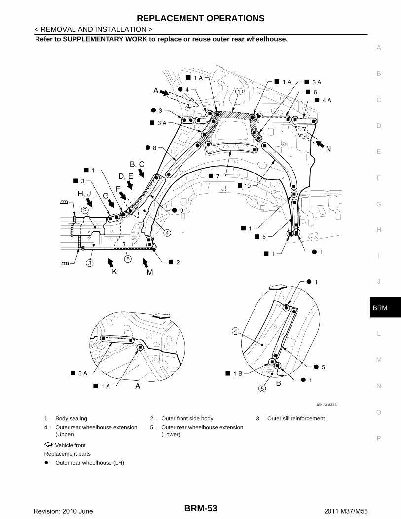
Refer to SUPPLEMENTARY WORK to replace or reuse outer rear wheelhouse.
1. Body sealing 2. Outer front side body 3. Outer sill reinforcement
4. Outer rear wheelhouse extension (Upper)
5. Outer rear wheelhouse extension (Lower)
: Vehicle front
Replacement parts
Outer rear wheelhouse (LH)
JSKIA1656ZZ
BRM-53Revision: 2010 June 2011 M37/M56
REPLACEMENT OPERATIONS
< REMOVAL AND INSTALLATION >
View C and E: Before installing outer front side body, outer sill reinforcement, and outer rear wheelhouseextension (Upper)View D: Before installing outer front side body and outer sill reinforcementView G: Before installing outer front side body, outer sill reinforcement, outer rear wheelhouse extension(upper), and outer rear wheelhouse extension (Lower)
1. Outer rear wheelhouse extension (Upper)
2. Outer rear wheelhouse extension (Lower)
Unit: mm (in)
: Vehicle front
: Drill φ8 mm (0.31 in) hole for the plug welding hole (ultra high strength steel plate).
JSKIA1657GB
BRM-54Revision: 2010 June 2011 M37/M56
REPLACEMENT OPERATIONS
C
D
E
F
G
H
I
J
L
M
A
B
RM
N
O
P
< REMOVAL AND INSTALLATION >
B
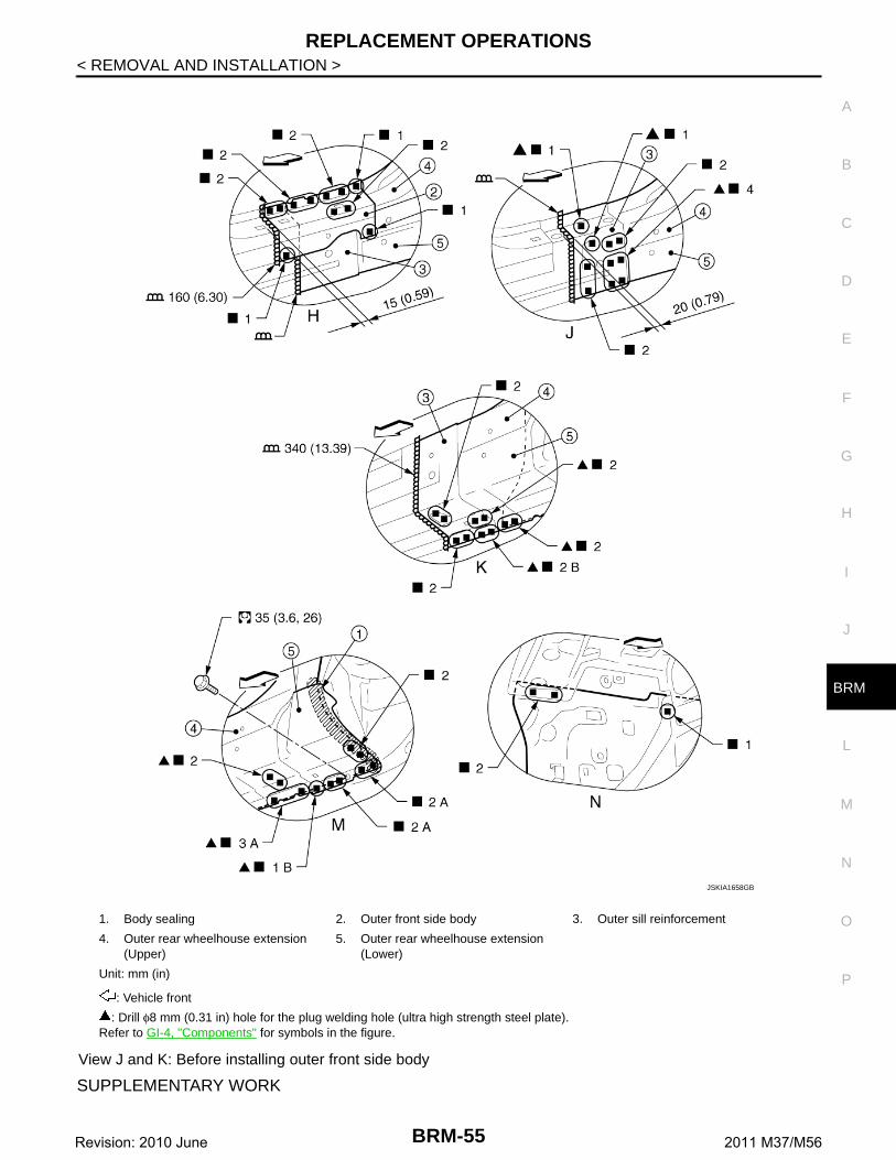
View J and K: Before installing outer front side body
SUPPLEMENTARY WORK
1. Body sealing 2. Outer front side body 3. Outer sill reinforcement
4. Outer rear wheelhouse extension (Upper)
5. Outer rear wheelhouse extension (Lower)
Unit: mm (in)
: Vehicle front
: Drill φ8 mm (0.31 in) hole for the plug welding hole (ultra high strength steel plate).Refer to GI-4, "Components" for symbols in the figure.
JSKIA1658GB
BRM-55Revision: 2010 June 2011 M37/M56
REPLACEMENT OPERATIONS
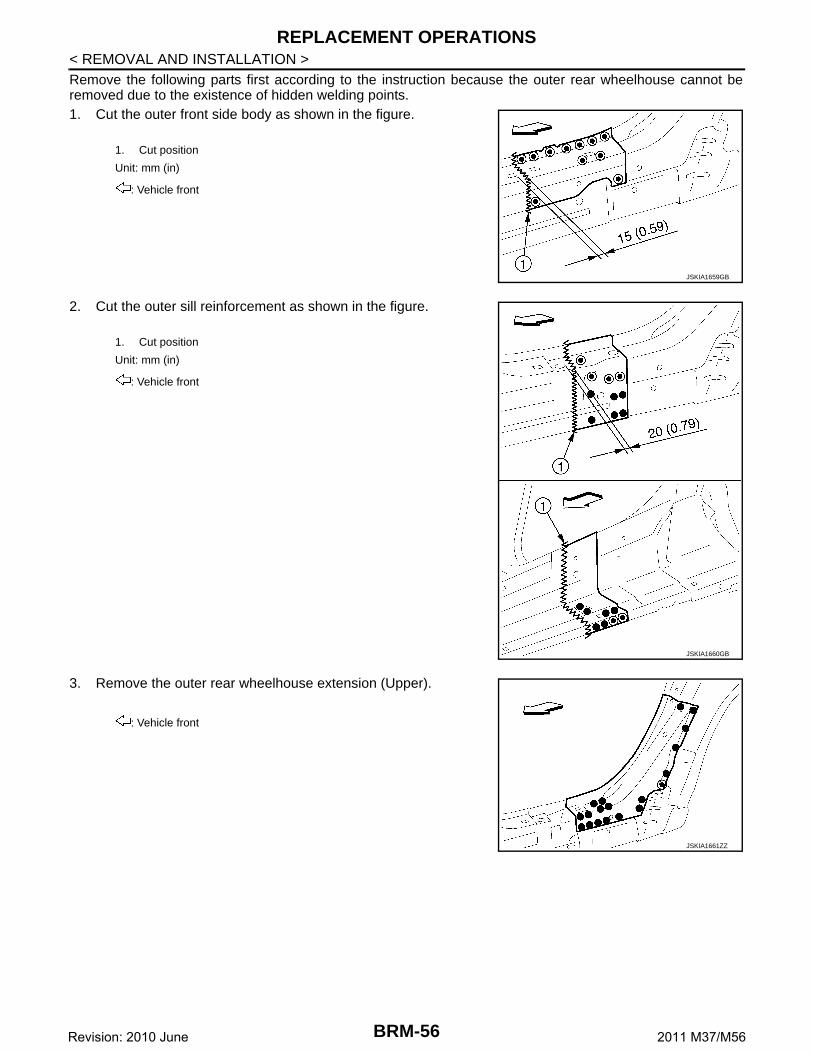
< REMOVAL AND INSTALLATION >Remove the following parts first according to the instruction because the outer rear wheelhouse cannot beremoved due to the existence of hidden welding points.1. Cut the outer front side body as shown in the figure.
2. Cut the outer sill reinforcement as shown in the figure.
3. Remove the outer rear wheelhouse extension (Upper).
1. Cut position
Unit: mm (in)
: Vehicle front
JSKIA1659GB
1. Cut position
Unit: mm (in)
: Vehicle front
JSKIA1660GB
: Vehicle front
JSKIA1661ZZ
BRM-56Revision: 2010 June 2011 M37/M56
REPLACEMENT OPERATIONS
C
D
E
F
G
H
I
J
L
M
A
B
RM
N
O
P
< REMOVAL AND INSTALLATION >
B
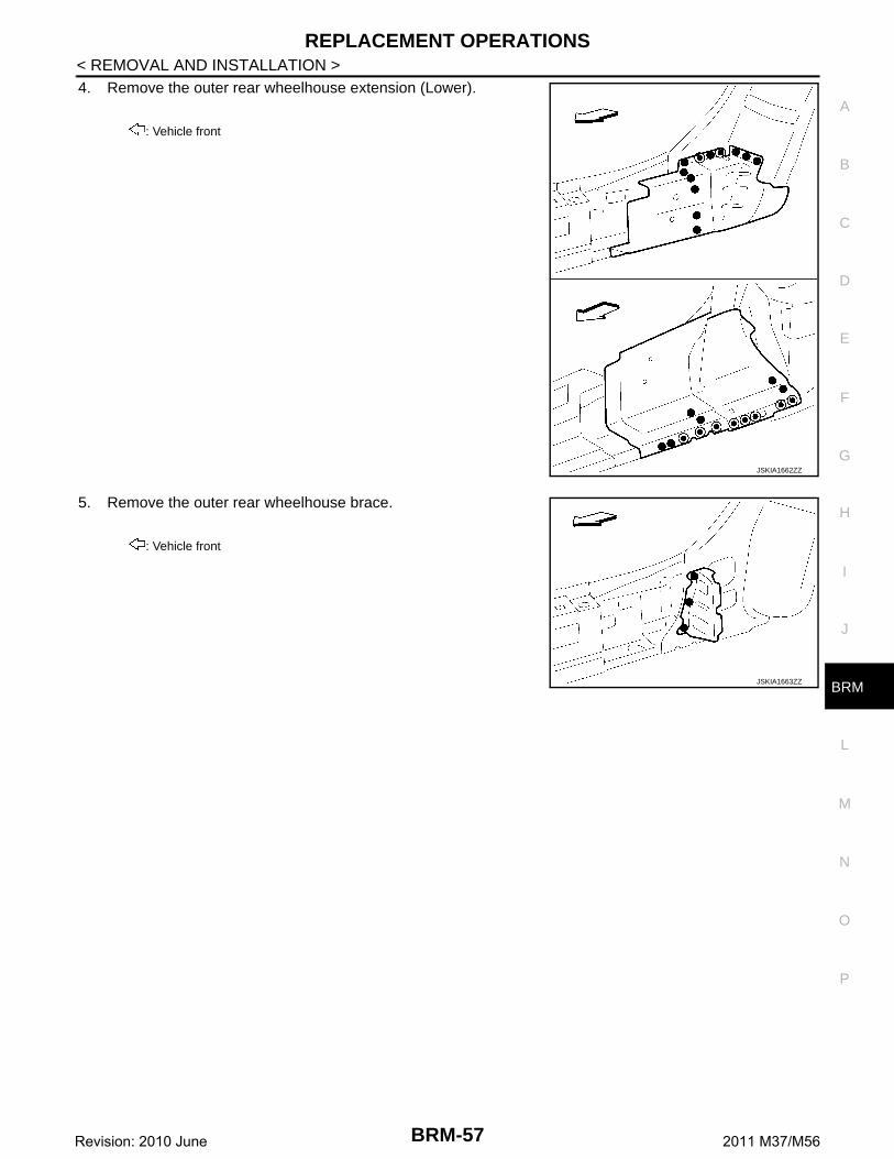
4. Remove the outer rear wheelhouse extension (Lower).
5. Remove the outer rear wheelhouse brace.
: Vehicle front
JSKIA1662ZZ
: Vehicle front
JSKIA1663ZZ
BRM-57Revision: 2010 June 2011 M37/M56
REPLACEMENT OPERATIONS
< REMOVAL AND INSTALLATION >
Rear Panel INFOID:0000000005927160
Rear Floor Rear INFOID:0000000005927161
Work after rear panel is removed.
: Welding method and the number of welding points apply to both side of the vehicle.
Replacement parts
Rear panel assembly
JSKIA1664ZZ
BRM-58Revision: 2010 June 2011 M37/M56
REPLACEMENT OPERATIONS
C
D
E
F
G
H
I
J
L
M
A
B
RM
N
O
P
< REMOVAL AND INSTALLATION >
B
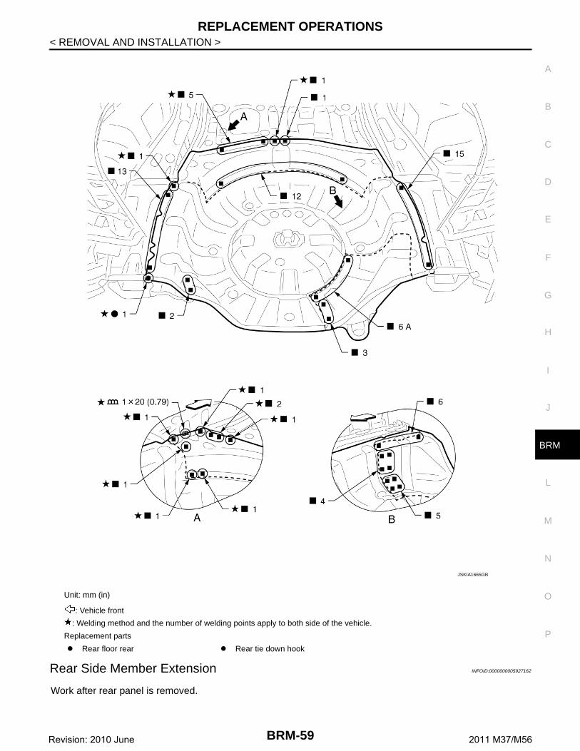
Rear Side Member Extension INFOID:0000000005927162
Work after rear panel is removed.
Unit: mm (in)
: Vehicle front
: Welding method and the number of welding points apply to both side of the vehicle.
Replacement parts
Rear floor rear Rear tie down hook
JSKIA1665GB
BRM-59Revision: 2010 June 2011 M37/M56
REPLACEMENT OPERATIONS
< REMOVAL AND INSTALLATION >
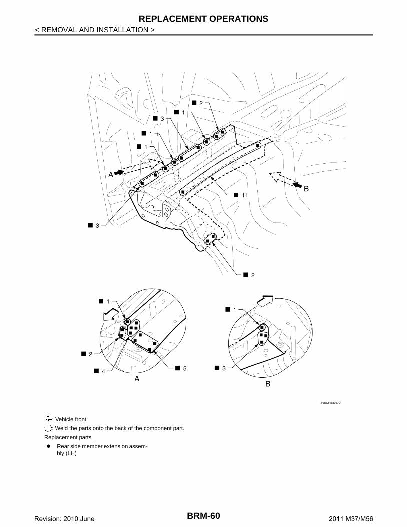
: Vehicle front
: Weld the parts onto the back of the component part.
Replacement parts
Rear side member extension assem-bly (LH)
JSKIA1668ZZ
BRM-60Revision: 2010 June 2011 M37/M56
BODY ALIGNMENT
C
D
E
F
G
H
I
J
L
M
A
B
RM
N
O
P
< SERVICE DATA AND SPECIFICATIONS (SDS)
B
SERVICE DATA AND SPECIFICATIONS (SDS)BODY ALIGNMENT
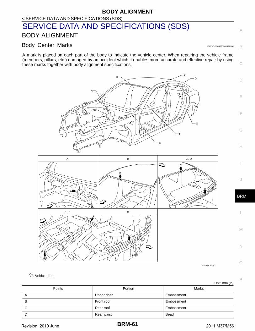
Body Center Marks INFOID:0000000005927166
A mark is placed on each part of the body to indicate the vehicle center. When repairing the vehicle frame(members, pillars, etc.) damaged by an accident which it enables more accurate and effective repair by usingthese marks together with body alignment specifications.
Unit: mm (in)
: Vehicle front
Points Portion Marks
A Upper dash Embossment
B Front roof Embossment
C Rear roof Embossment
D Rear waist Bead
JSKIA1876ZZ
BRM-61Revision: 2010 June 2011 M37/M56
BODY ALIGNMENT
< SERVICE DATA AND SPECIFICATIONS (SDS)
Description INFOID:0000000005927167
• All dimensions indicated in the figures are actual.• When using a tracking gauge, adjust both pointers to equal length. Then check the pointers and gauge itself
to make sure there is no free play.• When a measuring tape is used, check to be sure there is no elongation, twisting or bending.• Measurements should be taken at the center of the mounting holes.• An asterisk (*) following the value at the measuring point indicates that the measuring point on the other side
is symmetrically the same value.• The coordinates of the measurement points are the distances measured from the standard line of ″X″, ″Y″
and ″Z″.• ″Z″: Imaginary base line [200 mm (7.87 in) below datum line (″0Z″ at design plan)]
Engine Compartment INFOID:0000000005927168
MeasurementDimensions marked with ″*″ indicate symmetrically identical dimensions on both the right and left hand of thevehicle.
E Trans control reinforcement Hole 14×12 (0.55×0.47)
F Rear seat crossmember reinforcement Hole φ5 (0.20)
G Rear panel Indent
Points Portion Marks
1. Vehicle center 2. Front axle center 3. Imaginary base line
JSKIA0073GB
BRM-62Revision: 2010 June 2011 M37/M56
BODY ALIGNMENT
C
D
E
F
G
H
I
J
L
M
A
B
RM
N
O
P
< SERVICE DATA AND SPECIFICATIONS (SDS)
B
«The others»Unit: mm (in)
Measurement Points
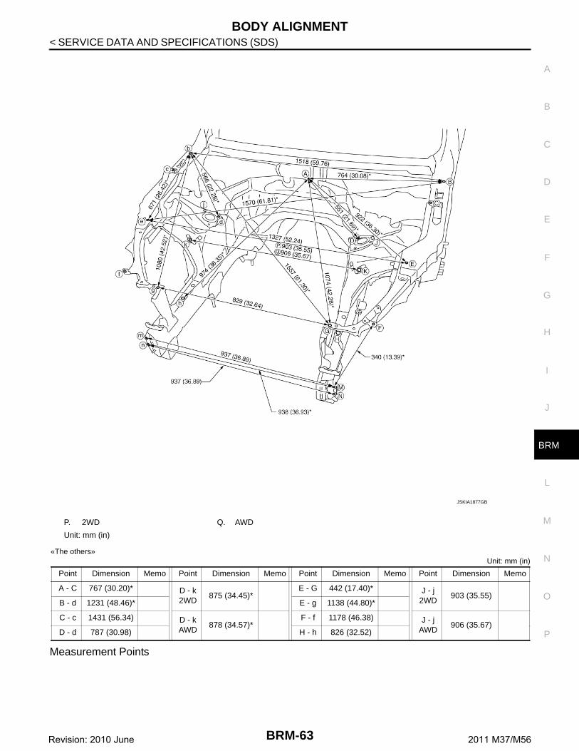
P. 2WD Q. AWD
Unit: mm (in)
Point Dimension Memo Point Dimension Memo Point Dimension Memo Point Dimension Memo
A - C 767 (30.20)* D - k2WD
875 (34.45)*E - G 442 (17.40)* J - j
2WD903 (35.55)
B - d 1231 (48.46)* E - g 1138 (44.80)*
C - c 1431 (56.34) D - kAWD
878 (34.57)*F - f 1178 (46.38) J - j
AWD906 (35.67)
D - d 787 (30.98) H - h 826 (32.52)
JSKIA1877GB
BRM-63Revision: 2010 June 2011 M37/M56
BODY ALIGNMENT
< SERVICE DATA AND SPECIFICATIONS (SDS)
Unit: mm (in)
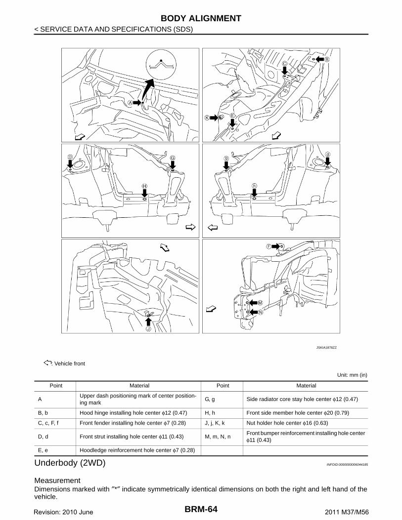
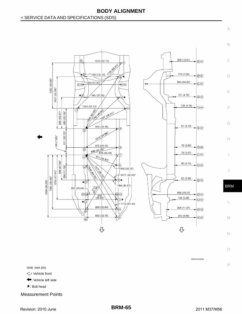
Underbody (2WD) INFOID:0000000006044185
MeasurementDimensions marked with ″*″ indicate symmetrically identical dimensions on both the right and left hand of thevehicle.
: Vehicle front
JSKIA1878ZZ
Point Material Point Material
AUpper dash positioning mark of center position-ing mark
G, g Side radiator core stay hole center φ12 (0.47)
B, b Hood hinge installing hole center φ12 (0.47) H, h Front side member hole center φ20 (0.79)
C, c, F, f Front fender installing hole center φ7 (0.28) J, j, K, k Nut holder hole center φ16 (0.63)
D, d Front strut installing hole center φ11 (0.43) M, m, N, nFront bumper reinforcement installing hole center φ11 (0.43)
E, e Hoodledge reinforcement hole center φ7 (0.28)
BRM-64Revision: 2010 June 2011 M37/M56
BODY ALIGNMENT
C
D
E
F
G
H
I
J
L
M
A
B
RM
N
O
P
< SERVICE DATA AND SPECIFICATIONS (SDS)
B
Measurement Points
Unit: mm (in)
: Vehicle front
: Vehicle left side
: Bolt head
JSKIA1616GB
BRM-65Revision: 2010 June 2011 M37/M56
BODY ALIGNMENT
< SERVICE DATA AND SPECIFICATIONS (SDS)
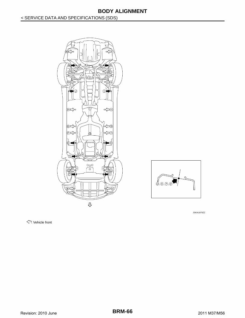
: Vehicle front
JSKIA1879ZZ
BRM-66Revision: 2010 June 2011 M37/M56
BODY ALIGNMENT
C
D
E
F
G
H
I
J
L
M
A
B
RM
N
O
P
< SERVICE DATA AND SPECIFICATIONS (SDS)
B
Unit: mm (in)
Underbody (AWD) INFOID:0000000006044186
MeasurementDimensions marked with ″*″ indicate symmetrically identical dimensions on both the right and left hand of thevehicle.
PointsCoordinates
Remarks PointsCoordinates
RemarksX Y Z X Y Z
A, a±415.8
(±16.370)−588.0
(−23.150)224.6
(8.843)Hole φ13 (0.51) H, h
±437.5(±17.224)
1810.0(71.260)
81.2 (3.197)
Hole φ16 (0.63)
B416.2
(16.386)−368.0
(−14.488)303.5
(11.949)Hole φ16 (0.63) J, j
±662.0(±26.063)
2354.0(92.677)
108.5(4.272)
Hole φ8 (0.31)
b−413.0
(−16.260)−368.0
(−14.488)303.5
(11.949)Hole φ16 (0.63) K, k
±472.6(±18.606)
2653.8(104.480)
120.8(4.756)
Bolt head
C, c±415.0
(±16.339)−104.0
(−4.094)133.5
(5.256)Bolt head M, m
±451.5(±17.776)
3213.9(126.531)
179.0(7.047)
Bolt head
D, d±392.0
(±15.433)414.0
(16.299)64.5
(2.539)Bolt head N, n
±535.0(±21.063)
3590.0(141.338)
328.3(12.925)
Hole 18×16 (0.71×0.63)
E, e±428.0
(±16.850)816.6
(32.150)80.0
(3.150)Hole 18×16 (0.71×0.63)
O, o±426.1
(±16.776)37.1
(1.461)665.8
(26.213)Hole φ50.1 (1.972)
F, f±438.0
(±17.244)1100.0
(43.307)78.0
(3.071)Hole φ16 (0.63) P, p
±531.3(±20.917)
2995.8(117.945)
864.1(34.020)
Hole φ68 (2.677)
G, g±437.5
(±17.224)1299.0
(51.142)76.0
(2.992)Hole φ16 (0.63)
BRM-67Revision: 2010 June 2011 M37/M56
BODY ALIGNMENT
< SERVICE DATA AND SPECIFICATIONS (SDS)
Measurement Points
Unit: mm (in)
: Vehicle front
: Vehicle left side
: Bolt head
JSKIA1617GB
BRM-68Revision: 2010 June 2011 M37/M56
BODY ALIGNMENT
C
D
E
F
G
H
I
J
L
M
A
B
RM
N
O
P
< SERVICE DATA AND SPECIFICATIONS (SDS)
B
: Vehicle front
JSKIA1880ZZ
BRM-69Revision: 2010 June 2011 M37/M56
BODY ALIGNMENT
< SERVICE DATA AND SPECIFICATIONS (SDS)
Unit: mm (in)
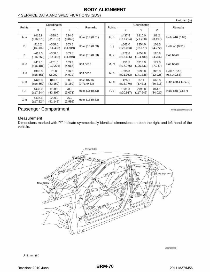
Passenger Compartment INFOID:0000000005927170
MeasurementDimensions marked with ″*″ indicate symmetrically identical dimensions on both the right and left hand of thevehicle.
PointsCoordinates
Remarks PointsCoordinates
RemarksX Y Z X Y Z
A, a±415.8
(±16.370)−588.0
(−23.150)224.6
(8.843)Hole φ13 (0.51) H, h
±437.5(±17.224)
1810.0(71.260)
81.2 (3.197)
Hole φ16 (0.63)
B416.2
(16.386)−368.0
(−14.488)303.5
(11.949)Hole φ16 (0.63) J, j
±662.0(±26.063)
2354.0(92.677)
108.5(4.272)
Hole φ8 (0.31)
b−413.0
(−16.260)−368.0
(−14.488)303.5
(11.949)Hole φ16 (0.63) K, k
±472.6(±18.606)
2653.8(104.480)
120.8(4.756)
Bolt head
C, c±411.0
(±16.181)−261.0
(−10.276)103.3
(4.067)Bolt head M, m
±451.5(±17.776)
3213.9(126.531)
179.0(7.047)
Bolt head
D, d±395.0
(±15.551)76.0
(2.992)126.3
(4.972)Bolt head N, n
±535.0(±21.063)
3590.0(141.338)
328.3(12.925)
Hole 18×16 (0.71×0.63)
E, e±428.0
(±16.850)816.6
(32.150)80.0
(3.150)Hole 18×16 (0.71×0.63)
O, o±426.1
(±16.776)37.1
(1.461)665.8
(26.213)Hole φ50.1 (1.972)
F, f±438.0
(±17.244)1100.0
(43.307)78.0
(3.071)Hole φ16 (0.63) P, p
±531.3(±20.917)
2995.8(117.945)
864.1(34.020)
Hole φ68 (2.677)
G, g±437.5
(±17.224)1299.0
(51.142)76.0
(2.992)Hole φ16 (0.63)
Unit: mm (in)
JSKIA1622GB
BRM-70Revision: 2010 June 2011 M37/M56
BODY ALIGNMENT
C
D
E
F
G
H
I
J
L
M
A
B
RM
N
O
P
< SERVICE DATA AND SPECIFICATIONS (SDS)
B
«The others»Unit: mm (in)
Measurement Points
Point Dimension Memo Point Dimension Memo Point Dimension Memo Point Dimension Memo
E - e 1431 (56.34) J - j 1485 (58.46) P - p 1338 (52.68) T - N 871 (34.29)*
E - g 1597 (62.87)* K - k 1501 (59.09) P - r 1586 (62.44)* T - O 796 (31.34)*
E - h 1627 (64.05)* M - m 1361 (53.58) Q - q 1468 (57.80) T - P 1076 (42.36)*
E - k 1681 (66.18)* M - o 1555 (61.22)* R - r 1522 (59.92) T - Q 923 (36.34)*
F - f 1494 (58.82) M - p 1521 (59.88)* S - E 930 (36.61)* T - R 821 (32.32)*
F - j 1800 (70.87)* M - r 1657 (65.24)* S - F 766 (30.16)* U - W 1220 (48.03)*
G - g 1513 (59.57) N - n 1485 (58.46) S - G 758 (29.84)* U - X 1206 (47.48)*
G - h 1908 (75.12)* N - q 1630 (64.17)* S - H 1390 (54.72)* V - W 1278 (50.31)*
G - k 1746 (68.74)* O - o 1501 (59.09) S - J 1279 (50.35)* V - X 1183 (46.57)*
H - h 1365 (53.74) O - p 1727 (67.99)* S - K 1125 (44.29)*
H - k 1565 (61.61)* O - r 1614 (63.54)* T - M 968 (38.11)*
JSKIA1881ZZ
BRM-71Revision: 2010 June 2011 M37/M56
BODY ALIGNMENT
< SERVICE DATA AND SPECIFICATIONS (SDS)
Unit: mm (in)
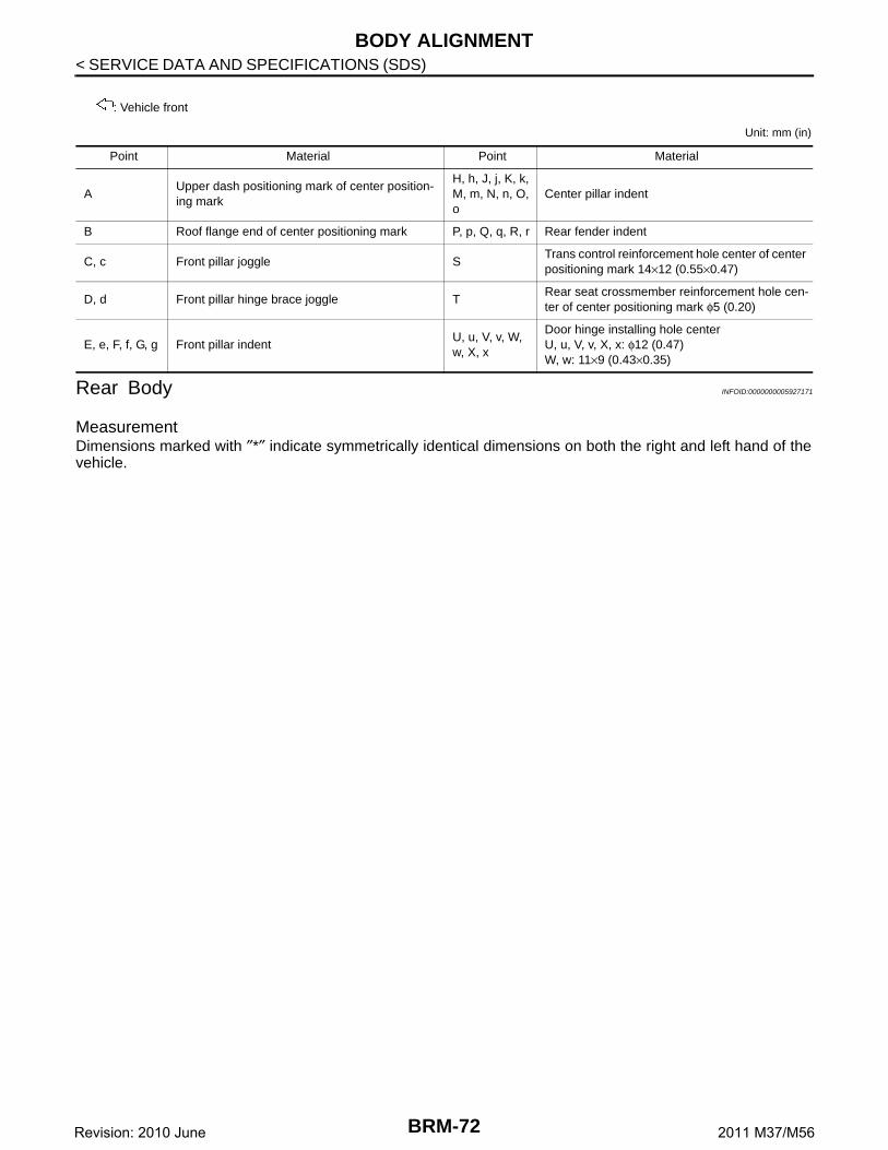
Rear Body INFOID:0000000005927171
MeasurementDimensions marked with ″*″ indicate symmetrically identical dimensions on both the right and left hand of thevehicle.
: Vehicle front
Point Material Point Material
AUpper dash positioning mark of center position-ing mark
H, h, J, j, K, k, M, m, N, n, O, o
Center pillar indent
B Roof flange end of center positioning mark P, p, Q, q, R, r Rear fender indent
C, c Front pillar joggle STrans control reinforcement hole center of center positioning mark 14×12 (0.55×0.47)
D, d Front pillar hinge brace joggle TRear seat crossmember reinforcement hole cen-ter of center positioning mark φ5 (0.20)
E, e, F, f, G, g Front pillar indentU, u, V, v, W, w, X, x
Door hinge installing hole centerU, u, V, v, X, x: φ12 (0.47)W, w: 11×9 (0.43×0.35)
BRM-72Revision: 2010 June 2011 M37/M56
BODY ALIGNMENT
C
D
E
F
G
H
I
J
L
M
A
B
RM
N
O
P
< SERVICE DATA AND SPECIFICATIONS (SDS)
B
Measurement Points
Unit: mm (in)
JSKIA1624GB
BRM-73Revision: 2010 June 2011 M37/M56
BODY ALIGNMENT
< SERVICE DATA AND SPECIFICATIONS (SDS)
: Vehicle front
JSKIA1625ZZ
Point Material Point Material
A Roof flange end of center positioning mark D Rear waist flange end of center positioning mark
B, b Outer side body joggle F, f, G, g Rear combination lamp base joggle
C, c, E, e Rear fender corner joggle HUpper rear panel indent of center positioning mark
BRM-74Revision: 2010 June 2011 M37/M56
LOCATION OF PLASTIC PARTS
C
D
E
F
G
H
I
J
L
M
A
B
RM
N
O
P
< SERVICE DATA AND SPECIFICATIONS (SDS)
B
LOCATION OF PLASTIC PARTS
Precautions for Plastics INFOID:0000000005927172
CAUTION:
• When repairing and painting a portion of the body adjacent to plastic parts, consider their characteristics (influence of heatand solvent) and remove them if necessary or take suitable measures to protect them.
• Plastic parts should be repaired and painted using methods suiting the materials, characteristics.
Abbre-viation
Material nameHeat resisting temperature
°C (°F)
Resistance to gasoline and solvents
Other cautions
PE Polyethylene 60 (140)Gasoline and most solvents are harmless if applied for a very short time (wipe out quickly).