Product Architect and Engineer Specifications Rev. N This Product Architect and Engineer Specifications document has been provided to assist you in the bidding process. This Microsoft Word ® file allows you to cut and paste Architect and Engineer Specifications directly into your proposal file. Each product A&E can be located using the alphabetical listing below and then clicking on the specific model number. Before proceeding, please click on and read the disclaimer below. DISCLAIMER INDEX A B C D E F G H I J K L M N O P Q R S T U V W X Y Z 1200 MacArthur Blvd., Suite 304
Transcript
Product Architect and Engineer Specifications Rev. N
This Product Architect and Engineer Specifications document has been provided to assist you in the bidding process. This Microsoft Word® file allows you to cut and paste Architect and Engineer Specifications directly into your proposal file.
Each product A&E can be located using the alphabetical listing below and then clicking on the specific model number. Before proceeding, please click on and read the disclaimer below.
A2, A2TThe loudspeaker shall be a NEAR Model A2 (8-ohm) or Model A2T (70V) in Black (BLK), White (WHT) or Green (GRN) or approved equivalent loudspeaker consisting of one 6-inch nominal low frequency transducer, one 1/2-inch nominal high frequency transducer mounted coaxially, with a filter network for dividing frequencies between the transducers. A weather-tight enclosure shall house all components. The enclosure shall be constructed from an injection-molded, high density (30% or greater), mineral-filled polypropylene material compounded with UV inhibitors.
Three molded-in colors shall be made available (Black, White, and Green). Perforated speaker grilles shall be made from heavy-gauge PVC, color-matched to the enclosure.
The low frequency driver shall utilize a metal-alloy cone with deep-anodized surface treatment for rigidity and corrosion resistance. The cone shall provide a heat transfer element for the voice coil under high power input. Compounded rubber cone surrounds shall be formulated to withstand all-environment installations, including salt spray, ultraviolet light (UV), heat, cold, and constant humidity. The voice coil will be centered via a high gauss, low viscosity magnetic fluid (ferrofluid), which increases the heat transfer rate from the voice coil under long-term, high-power use. The magnetic fluid shall prevent corrosion from occurring in the magnet gap.
The high frequency driver shall utilize an environmentally stable polycarbonate diaphragm. Ferrofluid shall dampen the voice coil and assist in the heat transfer for higher power capability.
Environmental testing shall ensure long-term operation in any weather. Specifications shall exceed Mil-Std-810E Test Methods for Temperature, Humidity, Ultraviolet Light, and Salt Spray.
The mounting bracket shall be designed with multiple angles to facilitate installation in corners or when angulation is required. An integral safety strap mounting point shall be included. The loudspeaker shall rotate, on its axis, a minimum of 180o. The bracket shall be formed from heavy-gauge aluminum (minimum 3mm thick), and finished with a scratch-resistant paint (color-matched to the enclosure).
The input connectors for 8-ohm and 70-volt systems shall be gold-plated screws with integral clamping washers.
Dimensions of each speaker shall not exceed 9" Diameter x 8" Deep. Weight shall not exceed 8 lb. (A2), and 10 lb. (A2T). The speaker shall be a NEAR Model A2 (8-ohm) or Model A2T (70V) in Black (BLK), White (WHT) or Green (GRN).
Part No. 54-8008-01CReturn to Index
A6, A6TThe loudspeaker shall be a NEAR Model A6 (8-ohm) or Model A6T (70V) in Black (BLK), White (WHT), or Green (GRN), or approved equivalent, loudspeaker consisting of one 6-inch nominal low frequency transducer, one
1-1/8-inch nominal titanium high frequency transducer with a filter network for dividing frequencies between the transducers. A weather-tight enclosure shall house all components. The enclosure shall be constructed from an injection-molded, high density (30% or greater) mineral-filled polypropylene material compounded with UV inhibitors.
Three molded-in colors shall be made available (Black, White, and Green). Perforated speaker grilles shall be made from heavy-gauge PVC, color-matched to the enclosure.
The low frequency driver shall utilize a metal-alloy cone with deep-anodized surface treatment for rigidity and corrosion resistance. The cone shall provide a heat transfer element for the voice coil under high-power input. Compounded rubber cone surrounds shall be formulated to withstand all-environment installations, including salt spray, ultraviolet light (UV), heat, cold, and constant humidity. The voice coil will be centered via a high gauss, low viscosity magnetic fluid (ferrofluid), which increases the heat transfer rate from the voice coil under long-term high-power use. The magnetic fluid shall prevent corrosion from occurring in the magnet gap.
The high frequency driver shall utilize an environmentally stable titanium diaphragm. Ferrofluid shall dampen the voice coil and assist in the heat transfer for higher power capability.
Environmental testing shall ensure long-term operation in any weather. Specifications shall exceed Mil-Std-810E Test Methods for Temperature, Humidity, Ultraviolet Light, and Salt Spray.
The mounting bracket shall be designed with multiple angles to facilitate installation in corners or when angulation is required. An integral safety strap mounting point shall be included. The loudspeaker shall rotate, on its axis, a minimum of 180o. The bracket shall be formed from heavy-gauge aluminum (minimum 3mm thick), and finished with a scratch-resistant paint (color-matched to the enclosure).
The input connectors for 8-ohm and 70-volt systems shall be gold-plated screws with integral clamping washers.
Dimensions of each speaker shall not exceed 7-1/8" W x 13-7/16" H x 7-11/16" D. Weight shall not exceed 11 lb. (A6) and 12 lb. (A6T).
Part No. 54-8009-01CReturn to Index
A8, A8TThe loudspeaker shall be a NEAR Model A8 (8-ohm) or Model A8T (70V) with a power handling capacity of 175W (8-ohm) or 64W (70V) or approved equivalent. The loudspeaker shall consist of one 8-inch nominal low frequency transducer and one 1-1/8-inch nominal titanium high frequency transducer with a filter network for dividing frequencies between the transducers. A weather-tight enclosure shall house all components. The enclosure shall be constructed from an injection-molded, high density (30% or greater) mineral-filled polypropylene material compounded with UV inhibitors.
Three molded-in colors shall be made available (Black, White, and Green). Perforated speaker grilles shall be made from heavy-gauge PVC, color-matched to the enclosure.
The low frequency driver shall utilize a metal-alloy cone with deep-anodized surface treatment for rigidity and corrosion resistance. The cone shall provide a heat transfer element for the voice coil under high-power input. Compounded rubber cone surrounds shall be formulated to withstand all-environment installations, including salt spray, ultraviolet light (UV), heat, cold, and constant humidity. The voice coil will be centered via a high gauss, low viscosity magnetic fluid (ferrofluid), which increases the heat transfer rate from the voice coil under long-term high-power use. The magnetic fluid shall prevent corrosion from occurring in the magnet gap.
The high frequency driver shall utilize an environmentally stable titanium diaphragm. Ferrofluid shall dampen the voice coil and assist in the heat transfer for higher power capability.
Environmental testing shall ensure long-term operation in all weather. Specifications shall exceed Mil-Std-810E Test Methods for Temperature, Humidity, Ultraviolet Light, and Salt Spray.
The mounting bracket shall be designed with multiple angles to facilitate installation in corners or when angulation is required. An integral safety strap mounting point shall be included. The loudspeaker shall rotate about its axis a minimum of 180o. The bracket shall be formed from heavy-gauge stainless steel (minimum 3mm thick), and finished with a scratch-resistant paint (color-matched to the enclosure).
The input connectors for 8-ohm and 70-volt systems shall be gold-plated screws with integral clamping washers.
Dimensions of each speaker shall not exceed 10-1/4" W x 17-7/8" H x 10-7/8" D. Weight shall not exceed 18 lb. (A8), and 20 lb. (A8T).
Part No. 54-8010-01DReturn to Index
A12The loudspeaker shall be a NEAR Model A12 with a power handling capacity of 225W (16-ohm) or 128W (70V) or approved equivalent. The loudspeaker shall consist of two 6.5" nominal low-frequency transducers and one 1.9" nominal mylar high-frequency transducer with a filter network for dividing and smoothing frequencies between the transducers. A mathematically-aligned, vented enclosure shall house all components. All vents shall be further protected from water ingress by acoustically transparent fabric designed to shed water. The enclosure shall be constructed from an injection-molded, high-density (30% or greater) mineral-filled polypropylene material compounded with UV inhibitors.
Enclosure shall be molded in black. Surface shall be able to accept paint. Perforated speaker grilles shall be made from color-matched perforated polypropylene, also able to accept paint if required.
The low-frequency drivers shall utilize a metal-alloy cone with deep-anodized surface treatment for rigidity and corrosion resistance. The cone shall provide a heat transfer thermal path for the voice coil under high-power inputs. Compounded rubber cone surrounds shall be formulated to withstand all-environment installations, including salt spray, ultraviolet light (UV), chlorine exposure, heat, cold, and constant humidity. The voice coil will be centered via a high-gauss, low-viscosity magnetic fluid (Ferrofluid), which increases the heat transfer rate from the voice coil under long-term high-power use. The magnetic fluid shall prevent corrosion from occurring in the magnet gap.
The high-frequency driver shall utilize an environmentally stable Mylar diaphragm. An integrated horn and phase compensation device shall provide increased output sensitivity and controlled coverage of the output.
The mounting yoke provided with the speaker shall be designed with a built-in angle to facilitate installation when downward angulation is required, as well as 180- degree left-to-right adjustment. The yoke shall be formed from heavy-gauge stainless steel (minimum 3mm thick), and finished with a scratch-resistant paint. In addition, an optional Adjustable Tilt-Mount Adapter (Model TMA812) shall be available which provides additional angles for precise orientation vertically over 18 specified points.
The input connectors for 16-ohm and 70-volt systems shall be gold-plated, rust-proof screws with integral clamping washers.
Dimensions of the loudspeaker shall not exceed 10-1/4" W x 17-7/8" H x 11-3/4" D. Weight shall not exceed 22 lb
Part No. 54-8023-41CReturn to Index
ACD2X2, ACD2X2UThe speaker shall be a Bogen Model ACD2X2 (or ACD2X2U) Drop-In Self-Amplified Ceiling Speaker, which shall be fully enclosed and constructed of industrial grade steel. It shall be comprised of a damped high-compliance factory-mounted 8" loudspeaker that shall consist of an 8" treated paper cone and a 10-ounce magnet, including a secondary cone.
The unit shall have a 1-watt amplifier. The typical current consumption shall be 1 CU (50 mA). Frequency response shall be 95 Hz - 12 kHz. Input sensitivity shall be 125 mVrms. Input impedance shall be 2k ohms. Dispersion shall be 100°.
The speaker shall have a non-reflective, off-white (or bright white for ACD2X2U) metal finish grille with a recessed volume control accessible through front grille. It shall include 4 seismic attachment points.
The speaker assembly will fit into 2' x 2' and 2' x 4' ceiling tiles. For 2' x 2' installations, a support rail shall not be needed and no cuts to the ceiling shall be necessary. For 2' x 4' installations, a single cut to the ceiling tile and an included support rail shall be needed.
The speaker shall measure 23-7/8" W x 5" H x 23-7/8" D and shall weigh 12 lb.
Part No. 54-8023-23DReturn to Index
ADP1Analog door phone shall be a Bogen Model ADP1.
The door phone shall be telephone line powered (18V DC / 20 mA minimum), answer a ring voltage of 40V AC RMS minimum, and have a ringer equivalence number of 0.7A.
Connection shall be made via a 2-position pluggable terminal block that is pre-wired to an RJ11 connector.
The ADP1 shall include controls for adjusting microphone level, speaker volume, and call timer duration.
The call timer shall be jumper defeatable.
The ADP1 shall include an auto answer feature.
The unit shall include a vandal-resistant brushed stainless steel faceplate with mounting gasket and heavy-duty call button and a plastic cone speaker with puncture-resistant, protective screen.
The ADP1 shall measure 5" W x 5" H x 1-3/4" D when fully assembled without the bezel and 6-1/4" W x 6-1/4" H x 1-3/4" D fully assembled with the bezel. It shall weigh 4 lb. The ADP1 shall fit into most indoor and outdoor dual gang electrical boxes with a minimum clearance of 4-5/8" W x 4-5/8" H x 2" D.
Part No. 54-8021-01AReturn to Index
AFDS2The amplifier failure detector and automatic substitutor shall be a Bogen Model AFDS2, or equivalent, capable of continuously supervising the operation of any main power amplifier and its standby amplifier in a sound system.
It shall be capable of detecting a loss of as little as 2 dB in either amplifier and automatically switch operation from main to standby amplifier, should the main amplifier be at fault. The failure of either amplifier shall be indicated by a corresponding front, panel-mounted LED and an aural fault alert tone. It shall be possible to silence the tone by depressing the SILENCE button, which shall automatically reset when the failure is corrected.
A 40 kHz signal, originated within the AFDS2, shall be pulsed into the inputs of the main and standby amplifiers and their outputs shall be continuously analyzed; if either amplifier should fall below 2 dB*, the AFDS2 shall be activated.
It shall be suitable for operation with, and capable of detecting failure in, any 25V or 70V balanced or unbalanced system.
The device shall be powered from either a 120V AC, 60 Hz line or a 12V DC source, with power consumption limited to 15W or 0.5A, respectively. Screwdriver-adjustable controls shall be provided on the unit for setting the sensitivity of the device and the level of the 40 kHz oscillator.
The unit shall be 19" W x 3-1/2" H x 7-1/2" D and shall weigh 8 lb. The panel shall be fabricated from #16 gauge cold-rolled steel and shall be finished in black enamel.
*Threshold is adjustable.
Part No. 54-7584-07BReturn to Index
AH5A, AH15AThe loudspeaker shall be a Bogen Model _____ amplified horn-type loudspeaker, or approved equivalent, and shall incorporate a ___-watt amplifier with volume control. (Specify AH5A/5-watt or AH15A/15-watt.) Frequency response shall be from 275 Hz to 14 kHz; dispersion shall be 110°. The loudspeaker shall operate from 24V DC source, and shall provide an input impedance of 1000 ohms.
AH5A
Maximum power output shall be 5 watts RMS. Sound pressure level, measured four feet on axis with 5 watt output @ 1 kHz shall be at least 116 dB. Typical operating current shall be 6 CU (300 mA). Sensitivity shall be 32 mV across 600 ohms.
AH15A
Maximum power output shall be 15 watts RMS. Sound pressure level, measured four feet on axis with 15 watt output @ 1 kHz shall be at least 121 dB. Typical operating current shall be 18 CU (900 mA). Sensitivity shall be 58 mV across 600 ohms.
The loudspeaker shall be of weatherproof, all-metal construction, with driver enclosed within a waterproof housing. A 4-conductor, color-coded cable shall be provided for quick connection to audio and power sources. The loudspeaker shall include a self-aligning, field-replaceable diaphragm. A plastic cover shall be provided for strain relief and to protect the volume control.
An all-purpose mounting bracket shall provide precise positioning in the vertical and horizontal planes with a single adjustment. The bracket shall include banding slots to permit mounting on beams and pillars. The bracket and loudspeaker shall be finished in textured mocha enamel. The unit shall measure 9" diameter x 9-1/4" deep. Product weight shall be 4 pounds.
Part No. 54-7757-04BReturn to Index
AMBSL1, AMBSQ1The speaker shall be a Bogen Model _____ (specify AMBSQ1 or AMBSL1) amplified loudspeaker, or equivalent, utilizing an 8" cone and a built-in amplifier with volume control. The frequency response shall be 110 Hz to 15 kHz.
For all models sensitivity shall be 125 mV and input impedance shall be 2000 ohms. The loudspeaker shall be powered by a suitable 24V DC power supply and shall consume 1 CU (50 mA) at typical operational levels. Sound pressure level, measured 1 meter on axis with 1W output shall be at least 92 dB.
The speaker enclosure shall be full steel construction and allow for surface mounting. The enclosure shall be painted off-white and measure ___ (specify 11-5/8" W X 11-5/8" H X 4-1/4" D for AMBSQ1 or 11-5/8" W X 11-3/8" H X 5-3/8" D [top] and 11-5/8" W X 11-3/8" H X 3-1/8" D [bottom] for AMBSL1). The speaker enclosure shall also provide Wiremold® knockouts. Product weight shall be 9 lb.
AMBSL1Front face shall be angled downward by 12.5 degrees.
Part No. 54-8023-34BReturn to Index
ANS1RThe ANS1R module shall have a maximum gain control that sets the maximum amount of gain added, from 0 dB to 22 dB of gain, once the ambient noise level surpasses the sound pressure level set by the ambient threshold. The ANS1R shall have a ramp speed control that sets the speed by which gain is added to the signal once the ambient noise level surpasses the threshold, from less than 1 dB/s to greater than 20 dB/s.
The module shall have an activity threshold control with a corresponding bi-color LED that will illuminate amber when at mix bus threshold. The ANS1R shall have an ambient threshold control that shall adjust the microphone input threshold from 64 dBSPL to 112 dBSPL with the same LED illuminating green when at mic threshold.
The ANS1R module shall have stereo unbalanced RCA inputs that provide 20 k-ohm input impedance. The unbalanced inputs shall be electronically mono-summed and connected to the amplifier’s front level control for the bay in which it is installed so that the input is not lost when using the output module. Or, it can be fed directly to the mix bus through the modules’ Aux level control, which bypasses the gain control function. The AUX level shall control the input source when jumpered to the mix bus only. Aux inputs shall have the ability to be muted by higher priority modules. It shall have a gradual fade back from mute when the mute control is deactivated. The module shall have a 4-pin input screw terminal barrier strip connector to make the input connection for the microphone and to connect a remote defeat switch (contact closure).
Part No. 54-8014-01R1Return to Index
ANS501, ANS500MThe Ambient Noise Sensor system shall consist of a Bogen Model ANS501 control module, a Bogen Model ANS500M microphone module, and a 12V/0.4A wall-mounted power supply. The system shall be designed to electronically adjust the level of a page announcement in an area where ambient noise levels are continuously changing.
The system shall continuously monitor the ambient noise level through the microphone module located in the subject area and change page signal levels to make pages audible over noise.
Up to four (4) microphone modules may be wired in parallel to monitor larger locations. The wire run between control unit and microphone module, when composed of 2-conductor AWG20, shall be able to reach a length of 2,000 feet with no appreciable loss of signal strength.
All wiring connections to the control module shall be made via pluggable screw terminals or RCA jacks.
The control module shall include controls for maximum boost; activity threshold; relative gain; AUX input level; ramp speed; and ambient MIC input threshold.
The control module shall include two unbalanced RCA inputs with mono summing stereo; balanced and unbalanced inputs; balanced and unbalanced outputs; a sensor MIC input; and a defeat input.
The control module shall include a mode switch and power and status LED’s.
The control module is designed to be wall-mounted. The microphone module shall include an adjustable mounting bracket for precise positioning.
The system shall be powered by a 12V power supply, which shall operate from 120V AC. Current draw shall not exceed 400 mA.
Dimensions of the control unit shall be 5-1/4" W x 3" H x 1-1/4" D. Dimensions of the microphone module shall be 2" W x 2-1/8" H x 7/8" D.
Part No. 54-8022-01AReturn to Index
AS1, ASWB1, ASUG1, ASWG1, ASUG1DK, ASWG1DKThe loudspeaker shall be a Bogen Model ________ (Insert AS1, ASWB1, ASUG1, ASWG1, ASUG1DK, or ASWG1DK) amplified loudspeaker, or equivalent, utilizing an 8" cone-type loudspeaker and a built-in amplifier with volume control, providing a frequency response from 100 Hz to 10 kHz.
(Use for All Models) Sensitivity shall be 125 mV and input impedance shall be 2000 ohms. The loudspeaker shall be powered by a suitable 24V DC power supply and shall consume 1 CU (50 mA) at typical operational levels.
Sound pressure level, measured four feet on axis with one watt output at 1000 Hz shall be at least 92 dB.
(Use for Model ASWB1) The loudspeaker shall be assembled in a wall baffle for surface mounting (with slight downward sound dispersion), constructed of 3/8" particle board in simulated walnut, with a black grille cloth. The unit shall measure 9-1/2" W x 9-1/2" H x 5-1/4" D (top), 4-1/8" D (base). The product weight shall be 8 lb.
(Use for Model ASUG1) The loudspeaker shall be assembled on a 12-7/8" diameter steel ceiling grille, finished in bright white semi-gloss enamel, for recessed installation. The loudspeaker shall include a fixed volume control knob. The product weight shall be 5 lb.
(Use for Model ASWG1) The loudspeaker shall be assembled on a 12-7/8" diameter steel ceiling grille, finished in off-white semi-gloss enamel, for recessed installation. The loudspeaker shall include a fixed volume control knob. The product weight shall be 5 lb.
(Use for Model ASUG1DK) The loudspeaker shall be assembled on a 12-7/8" diameter steel ceiling grille, finished in bright white semi-gloss enamel, for recessed installation. The loudspeaker shall include a detachable volume control knob. The product weight shall be 5 lb.
(Use for Model ASWG1DK) The loudspeaker shall be assembled on a 12-7/8" diameter steel ceiling grille, finished in off-white semi-gloss enamel, for recessed installation. The loudspeaker shall include a detachable volume control knob. The product weight shall be 5 lb.
Part No. 54-7764-04CReturn to Index
ASM1The speaker shall be a Bogen Model ASM1. The speaker shall have a 1-watt amplifier. The typical current consumption shall be 1 CU (50 mA). The frequency response shall be 125 Hz to 15 kHz. Dispersion angle shall be no less than 120°. Sensitivity, measured 1-watt @ 1 meter on axis, shall be a minimum of 90 dBspl. Input sensitivity shall be 125 mVrms. Input impedance shall be 2k ohms.
The speaker shall comply with NFPA National Code 160b that allows speakers to be installed in plenums and other air handling spaces. The speaker shall also comply with UL-2043 (report available).
The speaker shall be of durable ABS plastic construction and shall be mounted using specially designed studs that easily pierce ceiling tiles. The speaker shall have a front-mounted volume control. Custom-designed wing nuts shall be used for securing the speaker to the ceiling tile. Four standard wire nuts will connect the speaker wires to the studs. One set of studs shall be used to connect 24V (nominal) power, and the other set shall be used to connect an audio signal to the speaker. In each set of studs, color-coding will be used as a means of designating polarity. Copper-plated studs shall be positive (+) and nickel-plated studs shall be negative (-). The speaker shall include a large, rubber O-ring seal to hold the base of the speaker cavity tight to the ceiling tile. A tile bridge support (Model SMTB) shall be available for distributing the weight of the speaker in suspended ceilings.
The unit shall measure 9-1/2"?in diameter by 3" in depth. Base diameter against ceiling shall be 8-3/4". Product weight shall be 2 lb.
Part No. 54-8023-37CReturn to Index
AT10A, AT35AThe speaker line attenuator shall be a Bogen model (specify AT10A or AT35A), and shall permit setting the output level at loudspeakers on a 25V or 70V line without altering the amplifier volume setting. The attenuator shall provide a choice of 10 stops and an “off” position, and shall be capable of controlling up to 10-/35-watt speaker systems. The attenuator shall measure (2-7/8" W x 4-5/8" H x 3" D for AT10A or 4-3/4" W x 4-3/4" H x 2-1/2" D for AT35A) and weigh (1 lb. for AT10A or 2 lb. for AT35A).
Part No. 54-8023-33BReturn to Index
ATP10, ATP35The speaker line attenuator shall be a Bogen model (specify ATP10 or ATP35), and shall permit setting the output level at loudspeakers on a 25V or 70V line without altering the amplifier volume setting. The attenuator shall also have the ability to override the volume control setting when activated by 9V to 30V DC so that important and emergency messages will be heard at all speaker locations. The attenuator shall provide a choice of 10 stops and an “off” position, and shall be capable of controlling up to 10-/35-watt speaker systems. The attenuator shall measure (2-7/8” W x 4-5/8" H x 2-1/2" D for ATP10 or 4-3/4" W x 4-3/4" H x 2-1/2" D for ATP35), weigh (1 lb. for ATP10 or 2 lb. for ATP35), and feature etched faceplate markings.
Part No. 54-8023-33BReturn to Index
BAL2SThe BAL2S input module shall be a stereo, high-impedance, electronically-balanced input module. It shall be mutable by higher priority modules and shall feature an internal PCB jumper to enable or disable muting from the priority bus system. It shall have a continuously variable ducking control that will enable attenuation of the input signal from a minimum of 10 dB to a maximum of 48 dB relative to the normal unmuted condition. The module shall have a rapid mute when the mute function is activated and a gradual fade back from mute when the mute control is deactivated. Gain shall be switch selectable per channel and shall be 0 dB or +18 dB.
Part No. 54-5093-01DReturn to Index
BDT30AThe loudspeaker shall be a Bogen Model BDT30A, or approved equivalent, reentrant horn type loudspeaker. The frequency response shall be from 225Hz to 14kHz. Rated power output shall be 30 watts RMS continuous. Dispersion shall be 100º, each horn. Sound pressure level, measured four feet on axis with 30 watt input @ 1000Hz, shall be at least 121dB for each horn.
The unit shall incorporate a seven-position weather-sealed switch, to allow matching the loudspeaker to a 25V or 70V constant-voltage line. Power handling capacity shall be adjustable at 70V to 30, 15, 7.5, 3.7 or 1.8 watts, and at 25V to 15, 7.5, 3.7 or 1.8 watts.
The loudspeaker shall be of weatherproof all-metal construction, with driver enclosed within a waterproof housing. The loudspeaker shall include a self-aligning, field replaceable diaphragm.
Screw terminals shall be provided for connection to the audio line. A plastic cover shall be provided to protect the connectors and impedance selector switch, and to provide strain relief for the audio line.
An all-purpose mounting bracket shall provide precise positioning in the vertical and horizontal planes with a single adjustment. The bracket shall include banding slots to permit mounting the loudspeaker on beams or pillars. Bracket and loudspeaker shall be finished in textured mocha enamel. The unit shall measure 9-5/8" dia. (each horn) x 12-1/8" D. Shipping weight shall be 8 lb.
Part No. 54-7761-02D
Return to Index
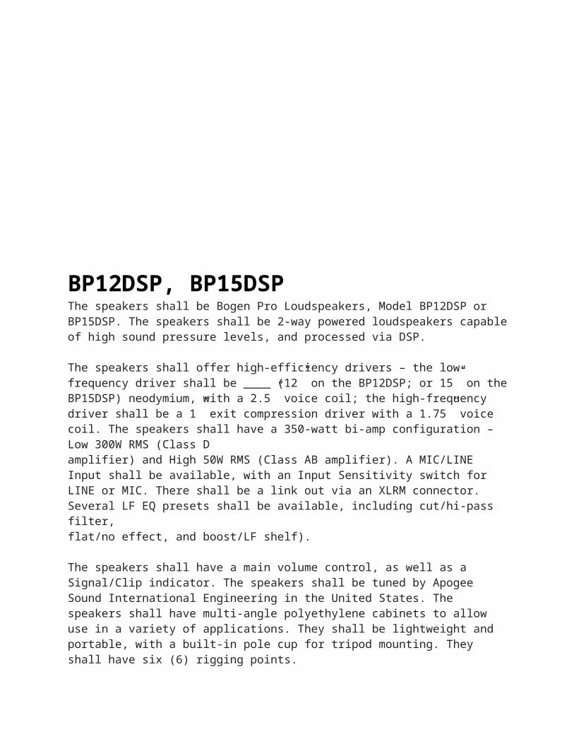
BP12DSP, BP15DSPThe speakers shall be Bogen Pro Loudspeakers, Model BP12DSP or BP15DSP. The speakers shall be 2-way powered loudspeakers capable of high sound pressure levels, and processed via DSP.
The speakers shall offer high-efficiency drivers – the low-frequency driver shall be ____ (12” on the BP12DSP; or 15” on the BP15DSP) neodymium, with a 2.5” voice coil; the high-frequency driver shall be a 1” exit compression driver with a 1.75” voice coil. The speakers shall have a 350-watt bi-amp configuration – Low 300W RMS (Class Damplifier) and High 50W RMS (Class AB amplifier). A MIC/LINE Input shall be available, with an Input Sensitivity switch for LINE or MIC. There shall be a link out via an XLRM connector. Several LF EQ presets shall be available, including cut/hi-pass filter,flat/no effect, and boost/LF shelf).
The speakers shall have a main volume control, as well as a Signal/Clip indicator. The speakers shall be tuned by Apogee Sound International Engineering in the United States. The speakers shall have multi-angle polyethylene cabinets to allow use in a variety of applications. They shall be lightweight and portable, with a built-in pole cup for tripod mounting. They shall have six (6) rigging points.
They shall measure _____________________(15-1/2” W x 26-1/8” H x 14-1/4” D for theBP12DSP; or 15-1/2” W x 26-1/8” H x 15-7/8” D for the BP15DSP) and weigh _______________ (38.5 for the BP12DSP; or 40.5 for the BP15DSP) lbs.
BPA60The amplifier shall be a Bogen BPA60 power amplifier or approved equivalent. It shall be of solid-state construction and shall have integrated circuits, silicon transistors and diodes to provide for continuous high-quality sound.
The rated output shall be achieved with an input signal not greater than 300mV (75mV with Model TL600 accessory transformer). The frequency response shall be flat within -2dB, from 20Hz to 20kHz. Hum and noise shall be at least 85dB below rated output. Output regulation shall be better than 2dB from no load to full load.
The amplifier shall supply 60 watts RMS from 50Hz to 15kHz at less than 2% THD into rated load impedances. Output impedances shall be 8-ohms/25V, 16-ohms, 25VCT and 70V. Power consumption shall not exceed 180 watts at full rated output. The amplifier shall measure 15-1/4"W x 3-1/2"H x 8"D ; weight shall not exceed 19 lbs.
Input impedances shall be: unbalanced, high impedance (50k-ohms); balanced/unbalanced, low impedance (600-ohms) with accessory transformer. Line bridging shall be possible using an accessory transformer. Overall gain shall be adjustable by means of an input level control located on the rear panel. A lo-cut filter switch shall provide -10dB attenuation at 100Hz.
The amplifier shall operate within a temperature range of -4°F to +131°F (-20° C to +55° C). A thermostat control shall be provided to prevent operation at excessive ambient temperatures. Additional overload protection shall be provided by transient protection diodes and a resettable electric circuit breaker.
The amplifier shall contain an illuminated on/off power switch, and shall operate from a 120V AC, 60Hz source. An auxiliary power receptacle (not switched) shall be provided, which shall be grounded, provided that the amplifier line cord is properly grounded.
The amplifier shall be designed for mounting within a standard 19-inch EIA equipment rack, using optional rack panel brackets.
Part No. 54-7609-06R2Return to Index
BRG1RThe BRG1R input module shall have a mono-balanced input and a buffered pseudo-balanced output that will enable the connection of several amplifiers to each other in a daisy chain configuration without creating ground loops between units. It shall have an RCA jack for both the input and the output connections. The module shall have a gain/trim control that will allow the gain to be adjusted plus or minus 5 dB relative to 0 dB nominal gain. It shall have the ability to mute lower priority modules and be muted by higher priority modules. The module shall be able to assume any of 4 priority levels. It shall have a continuously variable ducking control that will enable attenuation of the input signal from a minimum of 10 dB to a maximum of 48 dB relative to the normal unmuted condition and a gradual fade back from mute when the mute control is deactivated. The buffered output shall not be mutable. The module shall have a VOX/gating circuit to control muting of lower priority modules and an internal gating circuit with controls for threshold and duration. The module’s output shall be assignable to either or both of two mixing buses.
Part No. 54-5093-01DReturn to Index
BUFEXThe Level Controller shall be a continuously variable speaker attenuator that can remotely control the volume of a network of speakers, Bogen Model BUFEX. It shall provide output buffering for up to 150 self-amplified speaker inputs and allow speaker system expansion of existing 100V, 70V, or 25V central amplifier systems.
The BUFEX shall include a bypass function for overriding the volume control knob setting when activated by a contact closure or open collector output. A PCB-mounted bypass trim control shall adjust the volume when in bypass mode with a maximum of 12 dB of attenuation.
The BUFEX power consumption shall be 1 CU (50 mA) @ 24V DC.
The Tip (T) and Ring (R) connections shall be audio outputs with an output impedance of 8 ohms.
The BUFEX shall have a rugged and attractive stainless steel plate with engraved lettering.
The BUFEX shall measure 2-13/16" W x 4-9/16" H x 2-3/8" D and fit into a single gang electrical box. The BUFEX shall weigh 3 ounces.
Part No. 54-8023-15AReturn to Index
C10, C20The public address amplifier shall be a Bogen Model _________, or approved equivalent, with a full power rating of _______watts. (Specify:C10/10 watts or C20/20 watts.) The frequency response shall be 70Hz to 16kHz ±1dB, with less than 1% distortion at rated power output. Input sensitivity shall be 600µV for low-impedance balanced microphones, 85mV for auxiliary inputs, and 75mV for the telephone input. Hum and noise shall be 55dB below rated output for the MIC input, and 70dB below rated output for the AUX and TEL inputs.
The amplifier shall provide simultaneous mixing of two low-impedance balanced microphones and one telephone input; or one microphone, one auxiliary input, and one telephone input. The unit shall have a front panel selector switch which shall allow one of the input channels (MIC 2/AUX) to be selected for use as a microphone or an auxiliary input. It shall be possible to mute the auxiliary input when a customer-supplied SPST switch is attached to the AUX MUTE terminals on the rear panel.
The TEL input shall provide signal-activated paging with muting of the AUX channel. A VOX threshold control shall be included to eliminate activation of the channel by noise on the telephone line. The threshold control and TEL volume control shall be located on the rear panel.
The microphone inputs shall be equipped with filters to protect against RF interference. Independent volume controls and a treble cut control (-11dB @ 10kHz) shall be incorporated.
The amplifier shall provide output impedances of 4-, 8-, and 16-ohm speaker systems as well as for 25V and 70V constant voltage systems.
The amplifier shall contain a self resetting thermostat in the power transformer to protect against heat build-up and short circuited or overloaded connections.
The amplifier shall be mountable in 19-inch equipment racks, using an optional rack panel kit (Bogen Model RPK35B), or in a flush-in-wall mounting cabinet with tilt-out locking panel (Bogen Model WMK1). Dimensions shall be 11-3/8" W x 2-7/8" H x 7-3/8" D. Shipping weight shall be 5 lbs. for Model C10 and 6 lbs. for Model C20.
Part No. 54-7852-03R2Return to Index
C35, C60, C100The public address amplifier shall be a Bogen Model _________, or approved equivalent, with a full power rating of _______watts. (Specify: C35/35 watts, C60/60 watts or C100/100 watts.) The frequency response (transformer) shall be 70 Hz to 16 kHz ±2 dB @ 2 dB, with less than 1% distortion; 70 Hz to 16 kHz @ -2 dB. Input sensitivity shall be 600µV for low-impedance balanced microphones, and 85mV for auxiliary inputs. Hum and noise shall be 55 dB below rated output for the MIC inputs, and 70 dB below rated output for the AUX input.
The amplifier shall provide two low-impedance balanced microphone inputs, two Hi-Z auxiliary inputs, and one telephone line input. Active mixing of the inputs (2 MIC/1 AUX plus TEL, or 1 MIC/2 AUX, plus TEL) shall be provided. A switch shall be provided to select either the MIC 2 or AUX 1 input.
The microphone inputs shall be equipped with filters to protect against RF interference. Independent volume controls for each input as well as TREBLE control (±11 dB @ 10 kHz) and BASS control (±11 dB @ 100 Hz) shall be incorporated. A precedence circuit shall mute the AUX 2 input when a customer-supplied switch is actuated.
The amplifier shall provide output impedances of 4-, 8-, and 16-ohm speaker systems as well as for 25V and 70V constant voltage systems. Two high-impedance outputs shall be provided to drive a tape recorder or booster amplifier and, when used with an accessory transformer, to feed a 500/600-ohm telephone line.
The amplifier shall contain a resettable thermostat in the power transformer to protect against heat build-up and short-circuited or overloaded connections.
Provision shall be included to mount the amplifier in 19-inch equipment racks, using an optional rack panel kit (Model RPK50). Dimensions shall be 14-1/2" W x 3-3/4" H x 11" D. Shipping weight shall be ______lb. (Insert 16 lb. for C35, 18 lb. for C60 or 20 lb. for C100.)
Part No. 54-7853-01R2Return to Index
CA10A, CA11A, CA15C, CA17,CA19, & CA21BThe call-in switch shall be a Bogen Model ________ (specify CA10A, CA11A, CA15C, CA17, CA19, or CA21B), or equivalent, designed for flush- or surface-mount installation in a standard single-gang outlet box. It shall be mounted on a brushed aluminum faceplate, 4-1/2" H x 2-3/4" W, with beveled edges. The plate shall have two holes drilled to conform to the positions of the tapped holes on the outlet box. Two oval-head machine screws shall be supplied for mounting.
Use for all except CA17. The switch shall be furnished with insulated, color-coded connecting leads, stripped and tinned.
Use for CA10A. The switch shall be a two-position, rocker-type, single-pole, normally open switch, designed for use with Bogen PI35A and SI35A systems, and Bogen Multi-Graphic Series 115B, 2223, and 2233 systems. The depressed position shall be momentary. When pressed, the switch shall energize the corresponding annunciator lamp and the call-in tone at the room selector panel, and shall maintain this condition after the switch is released and until the call is acknowledged by the operator. The holding action shall be accomplished without the use of relays or other mechanical devices.
Use for CA11A. The switch shall be a three-position, rocker-type switch, designed for use with Bogen PI35A and SI35A systems, and Bogen Multi-Graphic Series 115B, 2223, and 2233 systems. It shall have two single-pole circuits that are open in the normal center position, labeled TALK. One circuit shall close when the switch is pressed downward, a momentary position that energizes the corresponding annunciator lamp and the call-in tone at the room selector panel. This condition shall be maintained after the switch is released and until the call is acknowledged by the operator. The holding action shall be accomplished without the use of relays or other mechanical devices. The other circuit shall close when the switch is pressed upward to the fixed position labeled PRIVACY. When the switch is in this position, it shall be impossible for the system operator to monitor the associated staff loudspeaker. However, this shall not affect the transmission of program material or intercommunication from the control center to the loudspeaker (privacy is not available with 2-wire call-in).
Use for CA15C. The switch shall be a two-position, rocker-type, single-pole, normally open switch, designed for use with Bogen Multicom 2000 systems. The depressed position shall be momentary. When pressed, the switch shall cause a designated administrative phone to ring. When pressed four times, it shall activate an “emergency call.”
Use for CA17. The switch shall be a two-position, push-button type, single-pole, normally open switch. It shall be designed for use with Bogen PI35A, SI35A, and Multi-Graphic systems equipped with the Bogen SCR25A module. The depressed, momentary position shall activate the corresponding annunciator lamp and the call-in tone at the room selector panel.
Use for CA19. The switch shall be a two-position, rocker-type, single-pole, normally open switch, designed for use with enhanced staff stations in Bogen Multicom 2000 systems. The depressed position shall be momentary. When pressed, the switch shall cause a designated administrative phone to ring. When pressed two times, it shall activate an “emergency call.”
Use for CA21B. The switch shall be a three-position, rocker-type switch, designed for use with Bogen Multicom 2000 systems. It shall have two single-pole circuits that are open in the normal center position, labeled TALK. One circuit shall close when the switch is pressed downward, a momentary position that shall cause a designated administrative phone to ring. When pressed three times, the switch shall activate an “emergency call.” The other circuit shall close when the switch is pressed upward to the fixed position labeled PRIVACY. When the switch is in this fixed position, it shall be impossible for an administrator to monitor the associated staff loudspeaker. However, this shall not affect the transmission of program material or intercommunication to the loudspeaker.
Part No. 54-7858-02BReturn to Index
CAM2The unit shall be a Bogen Model CAM2 or approved equivalent. It shall operate from 120V AC, 60 Hz. Inputs shall be provided for four balanced, low- impedance microphones and one high-impedance, high-level, auxiliary sound source. All microphone inputs shall use XLR connectors and have individual phantom power switches. Each input shall include a front-mounted clip indicator and the main output shall be monitored by a 5-segment LED meter. The pre-amplifier shall incorporate active mixing to minimize both mixing bus noise and interaction between channel gain controls, while providing excellent crosstalk isolation between channels. The pre-amplifier shall provide a balanced output that can be switched between providing a line-level or microphone-level output signal. A separate unbalanced line-level output shall be provided. A bridging input shall be provided that allows multiple CAM2 units to be interconnected without the need to use any of the MIC or AUX inputs. Operating parameters shall be as set forth in the Technical Specifications table above.
Part No. 54-5099-01BReturn to Index
CAM8PROThe unit shall be a Bogen Model CAM8PRO. Frequency response shall be 20 Hz to 20 kHz, ±1 dB. Power requirements shall be 18V AC center-tapped, 21V AC/120V AC at 60 Hz. The unit shall utilize an external power supply.
The unit shall measure 19" W x 1-3/4" H x 6" D, weigh 7 pounds, and be rack-mounted in a standard rack or placed on a flat surface.
The unit shall have 8 inputs, each with Main/AUX output selector, Gain/Trim Control, Input Level Control knob, Low Cut Filter, and MIC/Line switch.
The unit shall have balanced inputs and outputs with an Output Level Control knob for Main and AUX outputs.
The unit shall have an additional Auxiliary output.
The MIC inputs shall have switchable Phantom Power (+30V DC) for condenser microphones.
The unit shall be of heavy-duty construction with sealed potentiometers and pluggable terminal strip connections.
The CAM8PRO shall include a Compressor/Limiter with adjustable Threshold and Ratio Controls, an LED Bar Graph Output Meter, and a Bypass switch. It will also include a Headphone Output.
Part No. 54-8007-01CReturn to Index
CDR1The auxiliary program source shall be a Bogen Model CDR1 CD Player with AM/FM Receiver, or equivalent.
The program source shall include manual tuning and auto seek control. The auto seek control shall automatically ascend (or descend) the frequency scale to the next strong frequency. It shall be possible to program up to 5 bands (FM1, FM2, FM3, AM1, AM2) with up to 6 stations each for a total of 30 stations. A preset scan control shall be provided to scroll and select from available presets. The FM section shall have a frequency range from 87.5 MHz – 108 MHz, the AM section will have a frequency range of 520 kHz – 1620 kHz. Pluggable screw terminal inputs shall be available for an AM loop antenna, a FM dipole antenna, and for speaker outputs. An F-type coax antenna connector shall also be available.
The CD player system shall include Browse, Repeat, Random Play, and Pause functions. The CD player shall be capable of playing CD, CD-R, or CD-RW discs.
The CDR1 shall have a frequency response of 20 Hz – 20 kHz (< 5 dB).
The following controls shall be provided: Power/Volume, Disc Eject, Mode (Radio, CD, AUX), Audio/Menu Select (Volume, Bass, Treble, Balance, Display, Seek, and Clock), Mute, Scan, Stereo/Mono, Station Store/Select, Loudness Contour, Band, and Station Select. An LCD digital readout shall be provided to show selected frequency and band (in Radio Mode) or track (in CD Mode) information.
The unit shall operate on 12V DC (3A) power with an included desktop-style AC power adapter. It shall be possible to drive 8-ohm loudspeakers directly from 1W per channel (Right/Left) outputs. A 50-ohm mono-summed RCA output shall also be available, in addition to stereo.
The unit shall be 7-1/4" W x 2-1/8" H x 9-1/4" D and shall weigh 4 lb. The unit shall mount in a standard 19-inch rack system (2 rack spaces high) with the RK78 rack mounting kit (sold separately).
Part No. 54-8023-39AReturn to Index
CMP1RThe CMP1R module shall have a compressor ratio control adjustable from 2:1 to infinite to alter the dynamics of the signal above the limiting threshold. The module shall have a gain/trim control that will allow the gain to be compensated up to +15 dB relative to 0 dB nominal gain. The CMP1R shall have a threshold control adjustable from -40 dBV to +10 dBV with the center of rotation being approximately -10 dBV. The module shall also have a compression bypass switch to enable or disable the compression for instant comparison between compression and no compression while tuning the system.
The CMP1R module shall have an unbalanced RCA input that provides a 20 k-ohm input impedance. The unbalanced input shall connect to the amplifier’s front level control for the bay in which it is installed so that the input shall not be forfeited when using the output module. Aux inputs shall have the ability to be muted by higher priority modules. It shall have a gradual fade back from mute when the mute control is deactivated.
Part No. 54-8014-01R1Return to Index
CORE8X8The Digital Audio Platform shall be available with up to 16 inputs and outputs. Inputs/outputs shall be specified in blocks of 4, up to a total of 16. MIC/Line Input and line level output options shall be available. Inputs/outputs shall be analog, withinternal 24 bit A/D & D/A converters operating at a selectable sample rate of 48 kHz or 96 kHz. All internal processing shall be digital (DSP). Electronically balanced inputs and outputs shall be provided on plug-in barrier strip connectors. Inputs shall be individually programmable for either microphone or line-level audio signal and have assignable 48V Phantom Power. System shall be expandable to up to 12 total DSP units via RJ-45 Digital Links using standard CAT-5 data cabling, up to 32 feet between any two units max. Digital expansion links shall share up to 16 channels of digital audio at 48 kHz or 5 channels of digital audio at 96 kHz sampling rate between multiple units.
Internal system software shall be true drag-and-drop configuration with separate control/monitor GUI via direct data connection or via LAN/WAN using web browser TCP/IP protocol. Available system audio program components shall include (but not be limited to) various forms of: mixers, equalizers, filters, crossovers, dynamics/gain controls, feedback controller, routers, delays, remote controls, meters, noise/tonegenerators, and diagnostics. Ethernet communications shall be utilized for local or remote software control, configuration, and DSP distribution. After initial programming, systems may be controlled/monitored using either TCP/IP or RS-232 serial communication by third-party control systems (such as AMX® and Crestron®), by PC computer, and/or by dedicated remote control devices. Software shall operate on a PC computer running Windows® XP Professional/Vista/Windows 7.
DSP shall include two types of presets - “Master” and “Sub-Preset”. There shall be a minimum of 32 Master Presets, which will allow user to switch the unit between totally different preprogrammed designs. There shall also be a minimum of 16 Sub-Presets that allow user to switch to preprogrammed parameter settings within each Master Preset. The DSP shall incorporate an audio message player that can store up to 53 minutes of 8-bit audio or 18 minutes of 16-bit audio. Audio messages can be played either manually via direct PC selection, external analog or TTL logic input,microphone paging station programmable flex button, or automatically via internal event scheduler. Messages can be manually or automatically routed to any single or multiplezones/outputs. There shall be up to 128 schedules with up to 100 programmable scheduled events per schedule.
The DSP unit shall incorporate 16 logic inputs to trigger events or presets and other logic functions and 8 logic outputs with a common rail contact for controlling external functions. The unit shall also be equipped with 8 front panel control knobs, which shall be totally programmable for any variable function in the design program. This function knob shall also be 100% scalable to limit amount of volume/control. Front panel shall also have multi-color LED for displaying input/output signal presence, routing, and clipping indication for each input and output. DSP shall contain both TTL Logic and RS-485 serial control ports for communicating with a myriad of intelligent remote controls
and microphone paging stations. Remote Intelligent controls shall be either selector switch with volume knob in a5-position or 8-position style (RAC 5 or RAC 8), or an LCD window style with control wheel and selector buttons - (URC for monochrome RS-485) or (URC-200 for multi-color IP-based controller). There shall also be the capability for remote intelligent gooseneck paging stations which incorporate either programmable flex buttons with expansion button units, or touchscreen controllers. Multiple remote serial controldevices can also be daisy-chained by installing optional PPM-WJB junction box.The DSP unit shall be 1RU high, 17-1/8” x 1-3/4” x 11-5/8” (W x H x D). Product weight shall be 8 lb. DSP unit shall be factory warranted for 5 years.
Return to Index
CS1EZThe ceiling speaker shall be a Bogen Model CS1EZ, or approved equivalent ceiling speaker. The frequency response shall be 50 Hz to 12 kHz. The on axis sound pressure level shall be 95 dB, at least four feet with one watt input. Rated power output shall be 1 watt, RMS continuous. The unit shall have an impedance of 4900 ohms.
The ceiling speaker shall be comprised of an eight-inch cone speaker with a 70V matching transformer mounted on a steel ceiling grille painted with white enamel. The unit shall measure 13" Dia. by 3-1/4" D. Product weight shall be 3 lb.
Part No. 54-8006-01BReturn to Index
CSD1X2/U, CSD1X2VR/UThe speaker shall be a Bogen Model CSD1X2. It shall be a 1 ft. x 2 ft. steel assembly with non-reflective, finished metal grille; damped high-compliance factory-mounted 8" loudspeaker with a treated paper cone; and 70V/25V transformer. The 8" main speaker cone shall have a 10 ounce magnet. A secondary high frequency cone speaker shall be included in the assembly. The back of the assembly shall have a back can enclosure. The speaker shall include a seismic attachment point. Output shall be 94 dB @ 1W/1m (min.). Frequency response shall be 110 Hz - 20 kHz (min.). Transformer shall have power taps of 4, 2, 1, 0.5, and 0.25 watts, selectable by rotary switch. A support rail crossbar shall be included. The speaker shall measure 12-7/8" W x 4-3/4" H x 23-3/4" D. The speaker shall weigh 10 lb.
For CSD1X2: Front grille shall be off-white in color.
For CSD1X2U: Front grille finish shall be bright white in color.
For CSD1X2VR: Front grille finish shall be off-white in color. An easily accessible, front-mounted recessed volume control shall be included.
For CSD1X2VRU: Front grille finish shall be bright white in color. An easily accessible, front-mounted recessed volume control shall be included.
Part No. 54-9261-01G
Return to Index
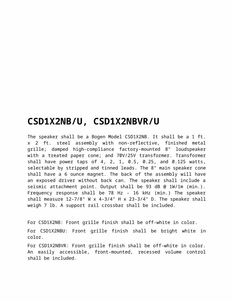
CSD1X2NB/U, CSD1X2NBVR/UThe speaker shall be a Bogen Model CSD1X2NB. It shall be a 1 ft. x 2 ft. steel assembly with non-reflective, finished metal grille; damped high-compliance factory-mounted 8" loudspeaker with a treated paper cone; and 70V/25V transformer. Transformer shall have power taps of 4, 2, 1, 0.5, 0.25, and 0.125 watts, selectable by stripped and tinned leads. The 8" main speaker cone shall have a 6 ounce magnet. The back of the assembly will have an exposed driver without back can. The speaker shall include a seismic attachment point. Output shall be 93 dB @ 1W/1m (min.). Frequency response shall be 78 Hz - 16 kHz (min.) The speaker shall measure 12-7/8" W x 4-3/4" H x 23-3/4" D. The speaker shall weigh 7 lb. A support rail crossbar shall be included.
For CSD1X2NB: Front grille finish shall be off-white in color.
For CSD1X2NBU: Front grille finish shall be bright white in color.
For CSD1X2NBVR: Front grille finish shall be off-white in color. An easily accessible, front-mounted, recessed volume control shall be included.
For CSD1X2NBVRU: Front grille finish shall be bright white in color. An easily accessible, front-mounted, recessed volume control shall be included.
Part No. 54-9279-01CReturn to Index
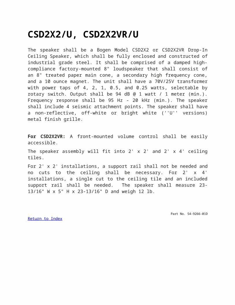
CSD2X2/U, CSD2X2VR/UThe speaker shall be a Bogen Model CSD2X2 or CSD2X2VR Drop-In Ceiling Speaker, which shall be fully enclosed and constructed of industrial grade steel. It shall be comprised of a damped high-compliance factory-mounted 8" loudspeaker that shall consist of an 8" treated paper main cone, a secondary high frequency cone, and a 10 ounce magnet. The unit shall have a 70V/25V transformer with power taps of 4, 2, 1, 0.5, and 0.25 watts, selectable by rotary switch. Output shall be 94 dB @ 1 watt / 1 meter (min.). Frequency response shall be 95 Hz - 20 kHz (min.). The speaker shall include 4 seismic attachment points. The speaker shall have a non-reflective, off-white or bright white (''U'' versions) metal finish grille.
For CSD2X2VR: A front-mounted volume control shall be easily accessible.
The speaker assembly will fit into 2' x 2' and 2' x 4' ceiling tiles.
For 2' x 2' installations, a support rail shall not be needed and no cuts to the ceiling shall be necessary. For 2' x 4' installations, a single cut to the ceiling tile and an included support rail shall be needed. The speaker shall measure 23-13/16" W x 5" H x 23-13/16" D and weigh 12 lb.
Part No. 54-9266-01DReturn to Index
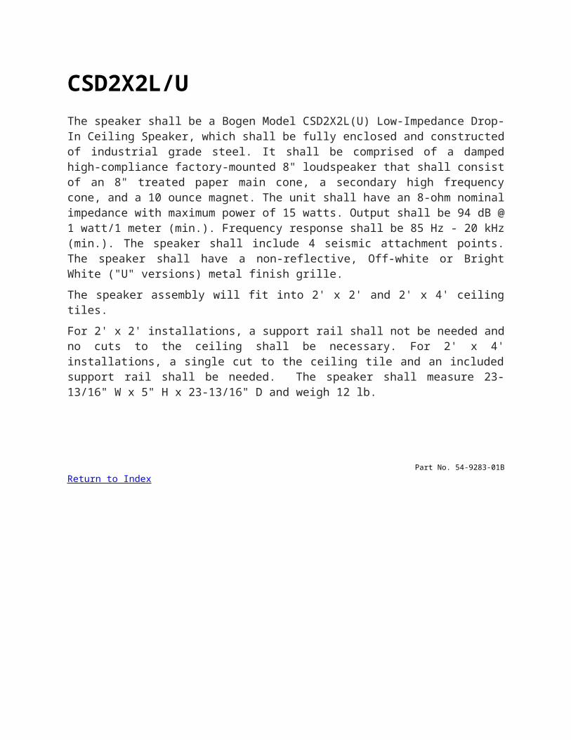
CSD2X2L/UThe speaker shall be a Bogen Model CSD2X2L(U) Low-Impedance Drop-In Ceiling Speaker, which shall be fully enclosed and constructed of industrial grade steel. It shall be comprised of a damped high-compliance factory-mounted 8" loudspeaker that shall consist of an 8" treated paper main cone, a secondary high frequency cone, and a 10 ounce magnet. The unit shall have an 8-ohm nominal impedance with maximum power of 15 watts. Output shall be 94 dB @ 1 watt/1 meter (min.). Frequency response shall be 85 Hz - 20 kHz (min.). The speaker shall include 4 seismic attachment points. The speaker shall have a non-reflective, Off-white or Bright White ("U" versions) metal finish grille.
The speaker assembly will fit into 2' x 2' and 2' x 4' ceiling tiles.
For 2' x 2' installations, a support rail shall not be needed and no cuts to the ceiling shall be necessary. For 2' x 4' installations, a single cut to the ceiling tile and an included support rail shall be needed. The speaker shall measure 23-13/16" W x 5" H x 23-13/16" D and weigh 12 lb.
Part No. 54-9283-01BReturn to Index
CSUBThe subwoofer shall be a Bogen Model CSUB or approved equivalent, consisting of one low frequency transducer in a band-pass alignment enclosure design.
The front baffle shall be injection-molded ABS material and the back can (enclosure) shall be heavy-gauge steel. All components shall be mounted inside the enclosure.
The baffle shall be supplied in off-white with a mild texture finish to promote paint adhesion, if desired. A perforated steel speaker grille shall be provided, color-matched to the baffle.
The driver shall utilize a compounded pulp diaphragm (cone). A compounded rubber cone surround shall be formulated to withstand environmental conditions with high or low heat, high or low humidity, and ultra-violet light
Integral swing-out clamps shall provide a secure installation in the ceiling surface without need for a separate tile bridge. The clamps shall be operated from either the front or the back of the speaker.
A safety cable attachment point shall be provided in the top of the enclosure for adding a 1/4-20 threaded forged eye bolt. An optional 10-foot long cable kit shall be available to serve as a backup safety cable (Model CK10). Use of the CK10 cable kit shall increase the depth of the speaker, and the minimum vertical clearance required, by 1-1/4".
The input connector shall be a 4-screw pluggable input connector, providing loop-through terminals for additional speakers.
Power input selection shall be via a front-mounted rotary switch, located under the removable grille. High impedance tap selections shall be 2, 4, 8, 16, 32, and 64 watts. A low impedance 8-ohm selection shall also be provided.
Dimensions of the speaker shall not exceed 15-1/2" diameter x 11" D. The speaker shall require a minimum vertical clearance of 11" (from front of mounting surface). Weight shall be 19 lb.
Part No. 54-8023-40AReturn to Index
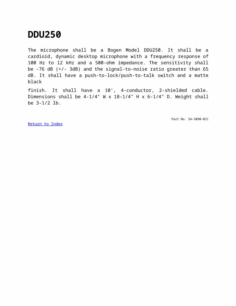
DDU250The microphone shall be a Bogen Model DDU250. It shall be a cardioid, dynamic desktop microphone with a frequency response of 100 Hz to 12 kHz and a 500-ohm impedance. The sensitivity shall be -76 dB (+/- 3dB) and the signal-to-noise ratio greater than 65 dB. It shall have a push-to-lock/push-to-talk switch and a matte black
finish. It shall have a 10', 4-conductor, 2-shielded cable. Dimensions shall be 4-1/4" W x 18-1/4" H x 6-1/4" D. Weight shall be 3-1/2 lb.
Part No. 54-5090-01CReturn to Index
DFT120The feedback termination device shall be a model DFT120, with 240 seconds of memory and the ability to record up to 16 messages while simultaneously playing previously recorded messages. The device’s operation shall be capable of automatic or external control.
The feedback terminator shall provide a frequency response from 100 Hz to 6.8 kHz +/-3 dB. Distortion shall be less than 1% over its bandwidth. The messages shall have a dynamic range of at least 60 dB and a signal to noise ratio of at least 60 dB.
The feedback terminator shall accommodate both loop start trunks and 4-wire dry loop interfaces, selectable by a slide switch. The input connector style for the interface shall be an RJ-11 type.
Further, the device shall provide an output capable of either 8 ohms @ 0.125W or 600 ohms @ +4 dBm, selectable by slide switch. The output connector style for the interface shall be an RJ-11 type. A control to adjust the output signal level shall be provided.
A bank of DIP switches shall be accessible to set device operating features. The feedback terminator shall have the ability to start recording based on dry loop, loop start, audio triggered, or DTMF activation methods. The device shall be capable of stripping the DTMF tones out of the recorded message in either the beginning or in the middle of the message. The device shall be able to regenerate DTMF tones in a message and to limit the number of DTMF tones a message can contain before the recording is aborted. The device shall allow for 2, 3, 4, or an unlimited number of DTMF tones in a message. The device shall allow a recording to be aborted by the issuance of 2 DTMF “#” digits in succession.
The selection of a pre-page tone shall be available. The recorded message shall be able to automatically replay and the time duration between message plays shall be selectable as 1, 2, 5, or 10 seconds.
The feedback terminator shall have contact closures that indicate if the unit is in use, playing and/or recording. An internal jumper shall be able to set the contact for normally open or normally closed operation.
The feedback terminator shall be wall mountable and use an external power supply. The power supply shall be UL and CSA listed.
Part No. 54-7885-02BReturn to Index
DRZ35The paging system shall be the Bogen DRZ35, a self-contained, 4-zone paging system for small- to medium-sized applications. It shall combine a digital tuner, and up to 3inputs (MIC, LINE, and AUX) with a 35-watt output. It shall be capable of driving 4-ohm speaker systems as well as 25V or 70V distributed systems. Pushbuttons on the front panel shall select between the TUNER or AUX input as a music source. The LINE and AUX inputs shall consist of mono-summimg RCA jacks to accept signal from a CD player or other line-level source. Bass, treble, and volume controls shall be provided to adjust the level of program and include a 5-segment LED output meter.
Individual controls for each input shall also be provided. The built-in tuner shall use a PLL synthesizer to provide accurate band selection. An LCD display shall be providedto display frequency readout. It shall be possible to program up to 10 FM and 10 AM preset stations. Push buttons shall be provided to select stations, program presets, and scan preset stations. Auto station search as well as manual tuning shall be available. An integral microphone input shall accept a balanced Lo-Z microphone. Input connection shall be via a three-pin XLR connector. A microphone volume control shall be provided. The input shall also include VOX-activated mute of program from TUNER, LINE, or AUX source. The unit shall supply 21V phantom power for use with condenser microphones.
The DRZ35 shall permit connection of up to four push button-selected paging zones. The unit shall also have LED output signal level indicators on the front panel.It shall be possible to supply telephone line input to the unit when an accessory transformer (Model WMT1A) is used. Outputs shall be provided for direct connection of 4-ohm speakers and for connection of 25 or 70 volt distributed systems. Four individual zone outputs shall be provided. The DRZ35 shall operate from a nominal 120V AC , 60Hz AC source, and shall be listed with a Nationally Recognized Testing Lab (NRTL) for U.S. and Canada. It shall meet FCC Part 15 requirements. It shall be rack-mountable using included mounting brackets. A 300-ohm/FM, 75-ohm FM(F-type) coax, and AM loop antenna connectors are provided. FM Dipole and AM Loop antenna are included. The unit shall include a circuit breaker. There shall be a masterpower switch as well as a separate power switch for the tuner. A red LED indicates power ON/OFF status for the unit.
Return to Index
DST1The tuner shall be a Bogen DST1 Digital Stereo Tuner. It shall incorporate a digital PLL-synthesized tuner for precise reception of FM and AM signals. All tuning shall be accomplished by pushbutton. An alphanumerical readout of frequency shall bedisplayed on a bright fluorescent display panel. FM frequency range shall be from 87.00 to 108.05 MHz. AM frequency range shall be from 530 to 1710 kHz. It shall be possible to select up to 60 total preset stations (FM/AM). It shall be possible to select stationsindividually by pushbutton or by scanning the preset stations.
A stereo and mono output of 1 volt minimum shall be provided via RCA jacks. A stereo output cable and remote control shall be included with the unit. A rear-mounted volume control shall be provided to attenuate the output signal. Connectors shall be provided for 75-ohm FM, 300-ohm FM, and AM loop antennas. FM dipole and AM loop antennas shall be included with the unit. The tuner shall operate from nominal 120V AC, 60 Hz.Dimensions shall be 16-7/8" W × 1-3/4" H × 10" D. With included feet for shelf placement, the unit shall be 2" H. Weight shall be 5 lb. The tuner shall be designed for shelf- or rack-mounted installation and shall be one rack space (1 RU) high. Removable rack mounting ears shall be included.
Return to Index
FG15B, FG15WThe speaker shall be a Bogen Model _____ (enter FG15B or FG15W) background and foreground speaker designed to complement sophisticated music systems.
- (Use for the FG15B) The speaker shall have a rugged molded black plastic housing. The driver shall consist of a 3” paper woofer and a 3/4” mylar tweeter. The speaker shall handle 15 watts @ 8-ohms or 1, 2, 4, 7.5, or 15 watts @ 70 volts.
- (Use for the FG15W) The speaker shall have a rugged molded eggshell white plastic housing. The driver shall consist of a 3” paper woofer and a 3/4” mylar tweeter. The speaker shall handle 15 watts @ 8-ohms or 1, 2, 4, 7.5, or 15 watts @ 70 volts.
The speakers shall include a “U” mounting bracket. Part No. 54-7867-02R2
Return to Index
FMH15TThe loudspeaker shall be a Bogen Model FMH15T, flange-mount, reentrant type horn loudspeaker. The frequency response shall be 475 Hz to 14 kHz. Rated power output shall be 15 watts, RMS continuous when driven by a 70V or 25V amplifier system. Dispersion shall be 95º. Sound pressure level, measured 1 meter on axis with 15-watt input shall be at least 122 dBspl and 111 dBspl with a 1-watt input.
The unit shall incorporate a seven-position weather-sealed switch, to allow matching the loudspeaker to a 70V or 25V constant-voltage line. Power handling capacity shall be adjustable at 15, 7.5, 3.6, 1.8, or 0.9 watts for 70V systems and 15, 7.0, 1.8, 0.9, 0.5, 0.25, or 0.125 watts for 25V systems. The loudspeaker shall be of weatherproof, vandal-resistant, all-metal construction. The loudspeaker shall include a self-aligning, field-replaceable diaphragm. Screw terminals shall be provided for connection to the audio line and a strain relief for the audio line will be provided.
Accessory flush- or surface-mount enclosures, a heavy-duty cast aluminum grille, and an adapter ring shall be available separately to complete installation of
the speaker.
The speaker shall have a black enamel finish. Its flange dimensions shall be 6-7/8" diameter and its body diameter shall be 5-5/8" with a depth of 5-1/4". Shipping weight shall be 4 lb.
Part No. 54-8023-28CReturn to Index
FMRThe background music/music-on-hold source shall be a Bogen Model FMR, especially designed to provide background music over a paging system, or supply music-on-hold to a telephone system. The unit shall have 1-watt and line-level outputs to facilitate connection to a variety of paging/telephone systems including an amplified speaker.
A built-in speaker shall make tuning easy. An LED indicator shall illuminate when the signal is strongest. Automatic frequency control (AFC) will prevent signal drift.
In addition to a built-in telescoping antenna, provisions shall be included to connect an external antenna. A tone control and output volume controls shall be included and shall be screwdriver-adjustable. Screw terminals shall be provided for the outputs, antenna, and 24V power source. A jack shall be included to connect a 12V receptacle-mount power supply. (Power supply not included - PRS40C recommended.) The FMR shall be 3-3/8" W x 6" H x 1-1/2" D, and shall include flanges for wall mounting.
Part No. 54-9142-04R2Return to Index
G8GThe loudspeaker shall be a Bogen Model G8G with a power handling capacity of 150W (8-ohm) or 64W (70V) or approved equivalent. The loudspeaker shall consist of one8-inch nominal low frequency transducer and one 1-inch nominal titanium high frequency transducer with a filter network for dividing frequencies between the transducers. A weather-tight enclosure shall house all components. The enclosure shall be constructed from a rotational molded, LLDPE (Linked Low-Density Polyethylene)compounded with UV inhibitors.
Perforated speaker grilles shall be made from heavy-gauge, stainless steel, color-matched to the enclosure. Available in green.
The low frequency driver shall utilize a metal-alloy cone with deep-anodized surface treatment for rigidity and corrosion resistance. The cone shall provide a heat transferelement for the voice coil under high-power input. Compounded rubber cone surrounds shall be formulated to withstand all-environment installations, including salt spray, ultraviolet light (UV), heat, cold, and constant humidity. The voice coil will be centered via a high gauss, low viscosity magnetic fluid (ferrofluid), which increases the heat transfer rate from the voice coil under long-term high-power use. The magnetic fluid shall prevent corrosion from occurring in the magnet gap.
The high frequency driver shall utilize an environmentally stable titanium diaphragm. Ferrofluid shall dampen the voice coil and assist in the heat transfer for higher powercapability.
Environmental testing shall ensure long-term operation in all weather. Designed to meet or exceed exceed Mil-Std- 810E Test Methods for Temperature, Humidity, UltravioletLight, and Salt Spray.
The input connectors for 8-ohm and 70-volt systems shall be multiple stripped and tinned wires provided to select power input levels at 2W, 4W, 8W, 16W, 32W, 64W Tapsettings.
Dimensions of each speaker shall not exceed 17-1/4" H x 13" W x 12-1/4" D. Product weight shall not exceed 14 lb.
Return to Index
GA-MLE3-E32Bogen Model GA-MLE3-E32 is an Explosion-Proof Loudspeaker manufactured by Atlas Sound® as their Model MLE-3T driver and MLE-32 horn assembly. The explosion-proof loudspeaker shall be UL listed for use in specified hazardous locations and/or combustible atmosphere as classified by the National Electric Code and specified as UL Class 1/Division 1/ Group B, C & D.
The loudspeaker shall have a UL approved compression driver for 30-watt distributed application with internally mounted 30-watt transformer. The transformer shall have primary impedance taps at 2500, 1300, 666, 333, 167, 89, and 45 ohms. Corresponding power taps for 70.7V line use shall be 1.8, 3.7, 7.5, 15, and 30. Power taps for 25Vline shall be 1.89, 3.7, 7, and 15. Secondary impedance shall be 8 ohms.
Driver and transformer shall be mounted within a heavy, cast aluminum housing. Voice coils shall be field-replaceable. Projector horn shall be a reflex type with polycarbonate re-entrant section for 95-degree sound coverage. Driver and horn assembly shall have a frequency response of 200 Hz – 10 kHz with sensitivity of -20 dBm (measured at 10dynes/cm2). Sound pressure level shall be a minimum of 110 dB (measured at 1W/1m).Return to Index
GA2The amplifier shall be a Bogen Model GA2, or equivalent, capable of delivering 1.5 watts at 2% THD, and 1 watt at 0.25% THD from 200 Hz to 15 kHz, +0 dB, -2.5 dB, into 8 ohms. It shall provide one high-impedance input with volume control, one 8-ohm output, and one 600-ohm output. Input impedance shall be 100 kilohms. Output level across balanced 600 ohms shall be 8 dBm/2V. Input sensitivity at full output shall be 50 mV or less; hum and noise shall be at least -72 dB below rated output. Inputs shall be via RCA-type phono jack or screw terminal strip. Output shall be via screw terminals.
The unit shall operate from 120V AC, 60 Hz and shall consume 4 watts. The unit shall measure 5-1/2"W x 4-1/8"H x 2-1/4"D. The shipping weight shall be 2 lb. A 5-1/2-foot AC power cord shall be provided.
Part No. 54-7767-03CReturn to Index
GA6AThe amplifier shall be a Bogen Model GA6A, or equivalent, capable of delivering 6 watts at not more than 1% total harmonic distortion from 75 Hz to 15 kHz. Frequency response shall be 30 Hz to 12 kHz, +0 dB, -3 dB. The amplifier shall provide one low-impedance, balanced or unbalanced microphone input and one high-impedance auxiliary input, with individual front panel controls and mixing capability. Microphone dynamic range shall be 46 dB with mic sensitivity of 0.3 mV. Auxiliary input sensitivity shall be 0.2V or better. Hum and noise shall be -50 dB for microphone, and -64 db for auxiliary inputs.Tone adjustment shall allow 9 dB treble boost or attenuation at 10 kHz, located on rear panel.
Outputs shall be provided on the rear panel for 8-ohm speaker and 25V and 70V lines. Output and microphone connections shall be made at rear-panel screw terminals; auxiliary input shall be via a rear panel RCA-type phono jack.
The amplifier shall operate from 120V AC, 60 Hz, and shall consume 16 watts. A rocker-type, front panel-mounted switch shall illuminate when the unit is switched on. Overload protection shall be by means of a thermally-actuated circuit breaker and a replaceable fuse. The chassis shall be constructed of zinc-plated galvanized steel with protective epoxy, and the cover from black vinyl-clad cold-rolled steel. The front panel shall be finished in black. The unit shall measure 8-1/2"W x 2-5/8"H x 6"D. The shipping weight shall be 5 pounds.
Part No. 54-7767-03CReturn to Index
GCU250The microphone shall be a Bogen Model GCU250. It shall be a cardioid, back electret condenser gooseneck microphone with a frequency response of 50 Hz to 18 kHz and a 250-ohm impedance. The sensitivity shall be -65 dB (+/- 3dB) and the signal-to-noise ratio greater than 65 dB. Max SPL @ 1% THD?shall be greater than 130 dB. It shall have a non-glare black finish. The GCU250 shall have an XLR?male type connector. It requires an external 9V - 52V DC phantom power source. Dimensions shall be 18-1/4" L x 3/4" Dia. Weight shall be 4 ounces.
Part No. 54-5090-01CReturn to Index
GDU150The microphone shall be a Bogen Model GDU150. It shall be a cardioid, dynamic gooseneck microphone with a frequency response of 100 Hz to 12 kHz and a 500-ohm impedance. The sensitivity shall be -75 dB (+/- 3dB) and the signal-to-noise ratio greater than 65 dB. It shall have a push-on/push-off talk switch mounted on its base and a non-glare black finish. The GDU150 shall have an XLR Male type connector. Dimensions shall be 17" L x 1-1/4" Dia. Weight shall be 1 lb.
Part No. 54-5090-01CReturn to Index
GS250The amplifier shall be a model GS250, rated at 250 watts RMS, with three-speed fan cooling.
The amplifier shall accommodate up to 6 Lo-Z balanced microphones, 2 Hi-Z auxiliary sources and a telephone paging input (MIC 5 shall be switch-selected for mic or telephone line; MIC 6 switch-selected for microphone or AUX 1). MIC 1 through 4 shall use XLR-type connectors; AUX input shall be via RCA phono jacks and all other connectors shall use screw terminals. Phantom power shall be supplied for use with condenser microphones. Microphone precedence connections shall be included for MIC 1, 2, 3, 5/TEL, 6/AUX 1, and AUX 2.
The amplifier shall provide a frequency response from 20 Hz to 20 kHz +0/-1 dB at rated power. Distortion shall be 0.3% typically, from 20 Hz to 20 kHz direct at rated power, and from 65 Hz to 20 kHz transformer @ -2 dB.
The amplifier shall include an Aphex Aural Exciter circuit, variable loudness contour control and dual-function equalizer. The equalizer shall be switch-selectable for feedback control or acoustic shaping and shall include 10 center-detent slide controls providing ±12 dB of boost or cut from 62.5 Hz to 16 kHz in acoustic mode and from 125 Hz to 8 kHz in feedback control mode.
The amplifier’s TEL input shall include automatic level control to provide consistent output regardless of who is paging, and a four-step VOX-activated AUX mute level. Provisions shall also be included for remote volume control, using an accessory control unit.
Outputs shall be provided for 4- and 8-ohm speakers and for 25V, 25VCT, and 70V distributed systems. Additional outputs shall be provided to feed a booster amp and tape recorder. A dedicated output shall permit feeding a 600-ohm telephone line using an accessory transformer (Model WMT1A). A Pre-amp out/power amp in circuit shall be provided to insert signal processing equipment.
The amplifier shall be rack mountable using an accessory rack panel kit. It shall be UL and CSA listed.
Part No. 54-7882-03CReturn to Index
GS150D/GS250DThe amplifier shall be a model _____, rated at ____ watts RMS (GS150D/150 watts, GS250D/250 watts).
The amplifier shall accommodate up to 6 Lo-Z balanced microphones, 2 Hi-Z auxiliary sources and a telephone paging input (MIC 5 shall be switch-selected for MIC or telephone line; MIC 6 switch-selected for MIC or AUX 1). MIC 1 through 4 shall useXLR-type connectors; AUX inputs shall be via RCA phono jacks and all other connectors shall use pluggable screw terminals. Phantom power shall be supplied for use with condenser microphones. Microphone precedence connections shall be included for MIC 1, 2, 3, 5/TEL, 6/AUX 1 and AUX 2.
The amplifier shall provide a frequency response from 65 Hz to 20 kHz +0/-2 dB at rated power. Distortion shall be 0.3% typically.
The amplifier shall include an Audio Enhancement circuit, variable loudness contour control, and dual function equalizer. The equalizer shall be switch selectable for feedback control or acoustic shaping and shall include 10 center-detent slide controlsproviding ±12 dB of boost or cut from 62.5 Hz to 16 kHz in acoustic mode and from 125Hz to 8 kHz in feedback control mode.
The amplifier shall include automatic level control to provide consistent output regardless of who is paging, automatic muting complete with a VOX circuit, and a variable mute level. Provisions shall also be included for remote volume control,using an accessory control unit (GSRVC).
Outputs shall be provided for 4- and 8-ohm speakers and for 25V, 25VCT, and 70V distributed systems. Additional outputs shall be provided to feed a booster amp and tape recorder. A dedicated output shall permit feeding a 600-ohm telephone line using an accessory transformer (Model WMT1A). A Preamp out/power amp in circuit shall be provided to insert signal processing equipment.
The amplifier shall be rack mountable using an accessory rack panel kit (GSDRPK). It shall carry the necessary safety agency listings for both the US and Canada.
Return to Index
HDO100The microphone shall be a Bogen Model HDO100. It shall be an omni-directional, dynamic handheld microphone with a frequency response of 70 Hz to 15 kHz and a 500-ohm impedance. The sensitivity shall be -72 dB (+/- 3dB) and the signal-to-noise ratio greater than 65 dB. It shall have a silent on/off lockable reed switch and a rubberized black finish. The HDO100 shall have an XLR Male connector. Dimensions shall be 6-1/2" D x 1-1/2" Dia. Weight shall be 1 lb.
Part No. 54-5090-01CReturn to Index
HDU150The microphone shall be a Bogen Model HDU150. It shall be a cardioid, dynamic handheld microphone with a frequency response of 70 Hz to 15 kHz and a 500-ohm impedance. The sensitivity shall be -70 dB (+/- 3dB) and the signal-to-noise ratio greater than 65 dB. It shall have a sliding-type on/off switch and a rubberized black finish. The HDU150 shall have an XLR Male connector. Dimensions shall be 6-1/2" D x 1-1/2" Dia. Weight shall be 1 lb.
Part No. 54-5090-01CReturn to Index
HDU250The microphone shall be a Bogen Model HDU250. It shall be a cardioid, dynamic handheld microphone with a frequency response of 50 Hz to 18 kHz and a 250-ohm impedance. The sensitivity shall be -72 dB (+/- 3dB) and the signal-to-noise ratio greater than 65 dB. It shall have a sliding-type on/off switch and a rubberized black finish. The HDU250 shall have an XLR Male connector. Dimensions shall be 7" D x 2" Dia. Weight shall be 1 lb.
Part No. 54-5090-01CReturn to Index
HFCS1/B, HFCS1LP/BThe loudspeaker shall be a Bogen Model HFCS1/B or HFCS1LP/B Ceiling Speaker or approved equivalent, consisting of one 6-1/2" (nominal) low frequency transducer, one 3/4" (nominal) high frequency transducer, and a filter network for dividing frequencies between the transducers.
The front baffle shall be injection-molded ABS material and the back can (enclosure) shall be plated steel. All components shall be mounted inside the enclosure.
The baffle shall be supplied in off-white with a mild texture finish to promote paint adhesion, if desired. A perforated steel speaker grille shall be provided, color-matched to the baffle.
The low-frequency driver shall utilize a molded polypropylene diaphragm (cone). A compounded rubber cone surround shall be formulated to withstand environmental conditions with high or low heat, high or low humidity, and ultra-violet light.
The high-frequency driver shall utilize a diaphragm consisting of black polycarbonate.
Integral swing-out clamps shall provide a secure installation in the ceiling surface. A safety cable attachment point shall be included in the removable terminal enclosure cover. An optional 10-foot long cable kit shall be available to serve as a backup safety cable (Model CK10). An optional tile bridge/support ring installation bracket shall provide additional support when mounting the loudspeaker into suspended ceilings (Model TBCR). The bracket shall also serve as a pre-installation guide for new construction installations, and provide attachment to either 16" OC or 24" OC mounting.
The input connector shall be a 4-screw pluggable input connector, providing loop-through terminals for additional speakers.
Power input selection shall be via a front-mounted rotary switch, located under the removable grille. High impedance tap selections shall be 1, 2, 4, 8, 16, and 32 watts. A low impedance 16-ohm selection shall also be provided.
Dimensions of the speaker shall not exceed 12-5/16" diameter x 12" D (HFCS1/B) or 12-5/16" diameter x 7-3/4" D (HFCS1LP/B). The speaker shall require a minimum vertical clearance of 11" (HFCS1/B) or 6-3/4" (HFCS1LP/B). Weight shall be 9 lb. (HFCS1/B) or 7-3/4 lb. (HFCS1LP/B).
Part No. 54-8016-03B
Return to Index
HFSF1The loudspeaker shall be a Bogen Model HFSF1 High-Fidelity, Small-Footprint ceiling speaker or approved equivalent, consisting of one 4" (nominal) low-frequency transducer; one 3/4" (nominal) high-frequency transducer; and a filter network for dividing frequencies between the transducers. Frequency response shall be 78 Hz to 20 kHz. Sensitivity, measured 1 watt at 1 meter, shall be 86 dBspl. Max. power input shall be 50W at 16 ohms, or 16W at 70V.
The front baffle shall be injection-molded ABS material and the enclosure (back can) shall be plated steel. All components shall be mounted inside the enclosure.
The baffle bezel shall be supplied in off-white with a mild texture finish to promote paint adhesion, if desired. A perforated steel speaker grille shall be provided, color-matched to the bezel.
The low-frequency driver shall utilize a molded polypropylene diaphragm (cone). A compounded rubber surround shall be formulated to withstand environmental conditions with high or low heat, high or low humidity, and ultra-violet light.
The high-frequency driver shall utilize a diaphragm consisting of black polycarbonate.
Integral swing-out clamps shall provide a secure installation in the ceiling surface. A safety cable attachment point shall be included on the side of the steel enclosure. An optional 10-foot long cable kit shall be available to serve as a backup safety cable (Model CK10). An optional tile bridge support installation bracket shall provide additional support when mounting the loudspeaker in suspended ceilings (Model TBSF).
The input connector shall be a 4-screw pluggable input connector, providing loop-through terminals for additional speakers.
Power input selection shall be via a front-mounted rotary switch, located under the removable grille. High- impedance tap selections (70V) shall be 16, 8, 4, 2, and 1 watts. A low-impedance 16-ohm input shall also be available via the rotary switch.
The speaker shall require a minimum vertical clearance of 7-1/8" from the front surface of the ceiling. Overall dimensions of the speaker shall not exceed 7-1/4" Diameter x 7-1/2" Deep. Weight shall be 4.5 lb.
Part No. 54-8023-38A
Return to Index
HS7EZ, HS15EZ, HS30EZThe loudspeaker shall be a Bogen Easy Design Horn Loudspeaker, Model HS7EZ, HS15EZ, or HS30EZ.
HS7EZRated power output shall be 7.5 watts RMS continuous. Frequency response shall be 250 Hz to 14 kHz. Dispersion shall be 120º. Sound pressure level shall be at least 105 dB*. Impedance shall be 653 ohms. The speaker shall feature a 12" lead wire for electrical connections.
HS15EZRated power output shall be 15 watts RMS continuous. Frequency response shall be 275 Hz to 14 kHz. Dispersion shall be 110º. Sound pressure level shall be at least 121 dB*. Impedance shall be 326 ohms. A screw terminal shall be provided for connection to the audio line.
HS30EZRated power output shall be 30 watts RMS continuous. Frequency response shall be 225 Hz to 14 kHz. Dispersion shall be 100º. Sound pressure level shall be at least 125 dB*. Impedance shall be 163 ohms. A screw terminal shall be provided for connection to the audio line.
The loudspeaker shall be of weatherproof, all metal construction. An all-purpose mounting bracket shall provide precise positioning in the vertical and horizontal planes with a single adjustment. The bracket shall include banding slots to permit mounting the loudspeaker on beams or pillars. Bracket and loudspeaker shall be finished in textured mocha enamel.
The driver shall be enclosed within a waterproof housing. The loudspeaker shall include a self-aligning, field-replaceable diaphragm.
A plastic cover shall be provided to protect the connectors and stepped volume control, and provide strain relief for the audio line.
The HS7EZ shall measure 6" diameter by 4" depth, the HS15EZ shall measure 9" diameter by 9-1/4", and the HS30EZ shall measure 11" diameter by 10-1/2" depth. Product weight shall be 2 lb., 5 lb., and 7 lb., respectively.
An I-beam mounting bracket (Model BC1) shall be available as an accessory.
* Sound pressure level measured four feet on axis with Rated power output @ 1 kHz.
Part No. 54-7888-01BReturn to Index
HTA125AThe power amplifier shall be a Bogen Model HTA125A or approved equal solid-state amplifier incorporating state-of-the-art MOSFET power transistors. Amplifiers utilizing conventional or bipolar power transistors shall not be acceptable.
The amplifier shall deliver an audio output of 125 watts (rms continuous). The total harmonic distortion shall be less than 0.5% at the 125-watt rating over the frequency range of 20 to 20,000Hz. The rated output shall be obtained with an input signal that is not greater than 500 millivolts (rms). Hum and noise shall be at least 90dB below rated output. The frequency response, when measured at full rated output, shall be flat within ±1dB, from 20 to 20,000Hz.
The amplifier shall provide either balanced or unbalanced constant-voltage outputs of 25 VCT and 70 volts, plus 4 and 8 ohm balanced or unbalanced outputs. Output regulation shall be within 2dB from no load to full load.
The amplifier shall provide an input of 50,000 ohms unbalanced high impedance, or 600 ohm balanced/unbalanced low impedance, or line bridging with an optional accessory plug-in transformer. Overall gain shall be adjustable by means of a single level control located on the rear panel. An internal low-cut filter (-10dB @ 100Hz) also shall be provided. The front of the amplifier shall contain an illuminated on/off power switch. The amplifier shall incorporate electronic shutdown circuitry which shall activate whenever an overload or short circuit occurs on the output of the amplifier. A front panel overload shutdown LED shall illuminate to indicate the discontinuance of power output; the circuitry shall automatically restore power output once the cause of the shutdown condition has been removed.
The amplifier shall operate from a 120 VAC, 60Hz source and shall consume 45 watts or less at idle and 260 watts at full rated output.
The amplifier shall have thermostatic control to prevent operation at excessive ambient temperatures. The amplifier also shall include electronic overload limiting, short-circuit protection and a 4 amp Slo-Blo fuse.
The amplifier shall have a standard EIA 19-inch front panel suitable for rack mounting. The amplifier shall be 19" wide, 5-1/4" high and 11" deep, finished in black and shall weigh 36 lbs.
Part No. 54-7790-04R2Return to Index
HTA250AThe power amplifier shall be a Bogen Model HTA250A or approved equivalent using power MOSFET circuitry.
The amplifier shall deliver an audio output of 250 watts (rms continuous). Total harmonic distortion shall be less than 0.5% at the 250-watt rating over the frequency range of 20 to 20,000 Hz. The rated output shall be obtained with an input that is not greater than 500mV (rms). Hum and noise shall be at least 90 dB below rated output. The frequency response, when measured at full rated output, shall be flat within ±1dB, 20 to 20,000 Hz.
The amplifier shall provide either balanced or unbalanced constant-voltage outputs of 25 VCT and 70 volts, plus 4 and 8 ohm balanced or unbalanced outputs. Output regulation shall be within 2dB from no load to full load.
The amplifier shall provide an input of 50,000 ohms unbalanced high impedance, or 600 ohms balanced or unbalanced low impedance, or line bridging with optional accessory plug-in transformers. Overall gain shall be adjustable by means of a single level control located on the rear panel. An internal low-cut filter
(-10dB @ 100Hz) shall also be provided. The front of the amplifier shall contain an illuminated on/off power switch. The amplifier shall incorporate electronic shutdown circuitry which shall activate whenever an overload or short occurs on the output of the amplifier. A front panel overload shutdown LED shall illuminate to indicate the discontinuance of power output; the circuitry shall automatically restore power output once the cause of the shutdown condition has been removed.
The amplifier shall operate from a 120 VAC, 60 Hz source and shall consume 60 watts or less at idle and 520 watts at full rated output. The amplifier shall have thermostatic control to prevent operation at excessive ambient temperatures. The amplifier also shall include electronic overload limiting, short-circuit protection and a 7-amp Slo-Blo fuse.
The amplifier shall have a standard EIA 19-inch front panel suitable for rack mounting. The amplifier shall be 19" wide, 5-1/4" high and 11" deep, finished in black and shall weigh 50 lb.
Part No. 54-7773-06BReturn to Index
IH8AThe loudspeaker shall be a Bogen Model IH8A reentrant horn-type loudspeaker, or approved equivalent, providing a frequency response from 350Hz to 12kHz. Input impedance shall be 8 ohms. Rated power output shall be 15 watts. Dispersion shall be 130°. Sound pressure level, measured four feet on axis at rated output, shall be at least 120dB.
The loudspeaker shall be of weatherproof, all metal construction, with driver enclosed within a waterproof housing. A 12-inch connecting cable shall be provided.
An all-purpose mounting bracket shall provide precise positioning in the vertical and horizontal planes. Bracket and loudspeaker shall be finished in textured mocha enamel. The unit shall measure 6-1/4" dia. x 6"D. The product weight shall be 2-1/2 lbs.
Part No. 54-7774-03R2Return to Index
KFLDS30T
The loudspeaker shall be a Bogen Model KFLDS30T. It shall be a wide dispersion, reentrant-type horn loudspeaker. The frequency response shall be 300 Hz to 12 kHz. Rated power output shall be 30 Watts RMS continuous when driven by a 70V amplified system and 15 Watts RMS when driven by a 25V amplified system. Dispersion shall be 70° × 95° with the rotatable horn flare allowing control of the dispersion orientation. Sound pressure level, measured 1 meter on axis at 30 Watts input, shall be at least 119 dBspl.The unit shall incorporate a seven-position weather-sealed switch to allow selection of output power taps. Power tap capacity shall be adjustable at 70V to 1.8, 3.7, 7.5, 15, or 30 Watts; and at 25V to 0.25, 0.5, 0.9, 1.8, 3.7, 7.5, or 15 Watts.The loudspeaker shall be of weatherproof aluminum construction with polycarbonate horn flare. The driver shall be enclosed within a waterproof housing. The loudspeaker shall include a self-aligning, field-replaceable diaphragm.Screw terminals shall be provided for connection to the audio line. A plastic cover shall be provided to protect the connectors and tap selector switch, and provide strain relief for the audio line. An optional terminal and tap selector fitting (Model TCSPT1, sold separately) shall allow placement of rigid or flex conduit to wrap to back of horn.An all-purpose mounting bracket shall provide precise positioning in the vertical and horizontal planes with a single wingnut adjustment. The bracket shall include banding slots to permit mounting the loudspeaker on beams or pillars and provisions for use of a Bogen BC1 beam clamp.Bracket and horn loudspeaker shall be finished in mocha. The unit shall measure 14-3/8" W × 8-1/4" H × 12-7/8" D. Shipping weight shall be 8 lb.
Part No. 54-8023-27BReturn to Index
LMM1S
The LMM1S module shall be a LINE/MIC level input module. Input shall be via front-mounted screw terminals. It shall have an internal, 24V DC phantom power supply that is enabled by a PCB jumper. The module shall have a gain control that will allow gain to be adjusted from 18 dB to 60 dB in MIC position, or from -2 dB to 40 dB in LINE position. It shall have the ability to mute lower priority modules and be muted by higher priority modules. The module shall be able to assume any of four priority levels. The module shall have an internal gating circuit with controls for threshold and duration. The module shall have bass and treble controls with cut and boost of 10 dB at 100 Hz and 10 kHz, respectively. The module’s output shall be assignable to either or both of two mixing buses.
Part No. 54-5093-01DReturn to Index
LMR1S
The LMR1S module shall be a LINE/MIC level input module with remote volume control capability. Input level control shall be by remote potentiometer or by direct voltage input (0 – 4.5V DC). Input shall be via front-mounted screw terminals. The LMR1S shall have an internal, 24V DC phantom power supply that is enabled by a PCB jumper. The module shall have a gain control that will allow gain to be adjusted from 18 dB to 60 dB in MIC position, or from -2 dB to 40 dB in LINE position. It shall have the ability to mute lower priority modules and be muted by higher priority modules. The module shall be able to assume any of four priority levels. The module shall have an internal gating circuit with controls for threshold and duration. It shall have a built-in limiter to control the maximum output level of the module. The module shall have an LED to indicate limiter activity. The module shall have bass and treble controls with cut and boost of 10 dB at 100 Hz and 10 kHz, respectively. The module’s output shall be assignable to either or both of two mixing buses.A Remote Volume Control Panel is included with the module. The panel shall be wall mountable and shall be able to control input level from a distance of up to 200 feet using a 2-conductor cable, or up to 2,000 feet using a 3-conductor shielded cable.
Part No. 54-5093-01DReturn to Index
M300, M450, M600The amplifier shall be a Bogen M-Class Amplifier, Model M600, M450 or M300. The amplifier shall provide a mono 70V output capable of 1200, 900 or 600 watts respectively or, it can provide two independent amplifier channels rated at 600, 450 or 300 watts/channel into 4 ohms, respectively.
The amplifier shall provide 2 module bays for the installation of various input modules. A dual-channel (balanced or unbalanced), high-impedance input module shall come installed as a standard module in the amplifier.
The amplifier shall be capable of 3 distinct modes of operation. These are Stereo, Dual Mono, and 70V Mono. In Dual Mono and 70V Mono, the amplifier shall provide the function of a 2 x 1 mixer of the installed input modules. Additionally, in the Dual Mono and 70V Mono modes, the amplifier shall allow one module to mute the other installed module if desired.
The amplifier shall drive the speaker load directly without the use of an output transformer. The amplifier shall allow a user-selectable low frequency roll-off of 65 Hz, 125 Hz, or no roll-off.
The amplifier shall have a defeatable sleep mode that greatly reduces idle power consumption when the amplifier has not received audio for more than 3 minutes. The amplifier shall also include a clip limiting feature that automatically reduces amplifier clipping.
The amplifier shall have three indicators that correspond to status, signal, and clip/limit.
The amplifier shall allow the connection of external signal processing equipment when in Dual Mono or 70V Mono modes. The signal flow shall automatically be diverted to external equipment when connected to the effects loop. The amplifier shall also provide both pre- and post-EQ signal feeds for distribution to other equipment.
The amplifier shall include a system that automatically compensates for surges or sags in AC line voltages of up to +/-10%. Additionally, the amplifier shall be protected against over-currents, overloads, excessive thermal dissipation, DC voltage, and short circuit on the outputs.
The amplifier shall be enclosed in a heavy-gauge steel chassis with recessed level control knob, which can be protected by a removable plastic cover. The amplifier shall be cooled by 2 independent continuously variable speed fans with easily removable fan filters.
The amplifier shall allow the attachment of rack ears (rear rack ears optional) and fit into a 19" rack using two rack spaces. It shall also allow the attachment of feet for tabletop placement.
Part No. 54-5092-01R2
Return to Index
MAX1RThe MAX1R module shall be a mono, high-impedance, unbalanced input module. The module shall have an RCA jack as its input connector. The module shall have a gain/trim control that will allow the gain to be adjusted from -20 dB to +6 dB relative to 0 dB nominal gain. It shall have the ability to mute lower priority modules and be muted by higher priority modules. The module shall be able to assume any of 4 priority levels. It shall have a continuously variable ducking control that will enable attenuation of the input signal from a minimum of 10 dB to a maximum of 48 dB relative to the normal unmuted condition and a gradual fade back from mute when the mute or gate control is deactivated. The module shall have a VOX/gating circuit to control muting of lower priority modules and its internal gating circuit, with controls for threshold and duration. The module shall have bass and treble controls with cut or boost of 10 dB at 100 Hz and 10 kHz, respectively. The module’s output shall be assignable to either or both of two mixing buses.
Part No. 54-5093-01DReturn to Index
MB8TSL, MB8TSQ, MB8TSLVR, and MB8TSQVR
The speaker shall be a Bogen Model _____ (specify MB8TSQ, MB8TSQVR, MB8TSL, or MB8TSLVR). The unit shall include an 8" paper cone speaker with 6 oz. magnet. The frequency response shall be 110 Hz to 15 kHz. Dispersion angle shall be no less than 100°. Sensitivity, measured 1 watt @ 1 meter on axis, shall be a minimum of 96 dBspl.The unit shall incorporate a transformer with tap selection wires corresponding to power settings of 4, 2, 1, 1/2, 1/4, and 1/8 watts for both 70V and 25V constant voltage speaker systems. Models with VR suffix shall feature a recessed volume control centered in the front speaker grille.The speaker enclosure shall be full steel construction and allow for surface mounting. The enclosure shall be painted off-white and measure ___ [specify 11-5/8" W X 11-5/8" H X 4-1/4" D for MB8TSQ(VR) or 11-5/8" W X 11-5/8" H X 5-3/8" D (top) and 11-5/8" W X 11-5/8" H X 3-1/8" D (bottom) for MB8TSL(VR)]. The speaker enclosure shall also provide Wiremold® knockouts.Front face of models MB8TSL(VR) shall be angled by 12.5 degrees downward. Product weight shall be 9 lb.
Part No. 54-8023-30DReturn to Index
MGN19The microphone shall be a Bogen Model MGN19 dynamic-type, omni-directional microphone. Frequency response shall be uniform from 50 Hz to 12 kHz, with a presence boost at 2 kHz for natural, intelligible sound. Impedance shall be 400 ohms. A sealed push-to-talk microswitch shall be mounted on the microphone housing. The sensitivity shall be -76 dB (+/- 3dB). The microphone shall be furnished with a 19" chrome-plated flexible gooseneck and mounting flange and seven feet of rugged synthetic-jacketed 4-conductor, 2-shielded cable. The microphone shall have a black Cycolac® cap and housing with chrome plated screen and shall measure 4-5/8" long with a maximum diameter of 1-3/8". Removable set screws shall secure the front cap to the microphone and the microphone to the gooseneck. Dimensions shall be 23-1/2" L x 1-1/4" Dia. Weight shall be 1-1/4 lb.
Part No. 54-5090-01CReturn to Index
MIC1SThe MIC1S module shall have a transformer-isolated, balanced input with screw terminal connector. It shall interface with low-impedance dynamic microphones. It shall also interface with electret condenser microphones and shall have an internal 24V DC phantom power supply to provide the bias supply that is enabled by a PCB jumper. The module shall have a gain control that will allow the gain to be adjusted from 28 dB to 62 dB. It shall have the ability to mute lower priority modules and be muted by higher priority modules. The module shall be able to assume any of 4 priority levels. The module shall have a VOX/gating circuit to control muting of lower priority modules and its internal gating circuit with controls for threshold and duration. It shall have a built-in limiter, with a threshold control, to limit the maximum output level of the module. A front panel LED will indicate limiter activity. The module shall have bass and treble controls with cut or boost of 10 dB at 100 Hz and 10 kHz, respectively. The module’s output shall be assignable to either or both of two mixing buses.
Part No. 54-5093-01DReturn to Index
MIC1XThe MIC1X module shall have a transformer-isolated, balanced input with XLR connector. It shall interface with low-impedance dynamic microphones. It shall also interface with electret condenser microphones and shall have an internal 24V DC phantom power supply to provide the bias supply that is enabled by a PCB jumper. The module shall have a gain control that will allow the gain to be adjusted from 28 dB to 62 dB. It shall have the ability to mute lower priority modules and be muted by higher priority modules. The module shall be able to assume any of 4 priority levels. The module shall have a VOX/gating circuit to control muting of lower priority modules and its internal gating circuit with controls for threshold and duration. It shall have a built-in limiter, with a threshold control, to limit the maximum output level of the module. A front panel LED will indicate limiter activity. The module shall have bass and treble controls with cut or boost of 10 dB at 100 Hz and 10 kHz, respectively. The module’s output shall be assignable to either or both of two mixing buses.
Part No. 54-5093-01DReturn to Index
MIC2SThe MIC2S module shall have an electronically-balanced input with screw terminal connector. It shall interface with low-impedance dynamic microphones. It shall also interface with electret condenser microphones and shall have an internal 24V DC phantom power supply to provide the bias supply that is enabled by a PCB jumper. The module shall have a gain control that will allow the gain to be adjusted from 18 dB to 62 dB. It shall have the ability to mute lower priority modules and be muted by higher priority modules. The module shall be able to assume any of 4 priority levels. The module shall have a VOX/gating circuit to control muting of lower priority modules and its internal gating circuit with a threshold control. It shall have a built-in limiter, with a threshold control, to limit the maximum output level of the module. The module shall have bass and treble controls with cut only of 10 dB at 100 Hz and 3 kHz, respectively. The module shall have a voice enhancement control for improving voice intelligibility. The module’s output shall be assignable to either or both of two mixing buses.
Part No. 54-5093-01DReturn to Index
MIC2XThe MIC2X module shall have an electronically-balanced input with XLR connector. It shall interface with low-impedance dynamic microphones. It shall also interface with electret condenser microphones and shall have an internal 24V DC phantom power supply to provide the bias supply that is enabled by a PCB jumper. The module shall have a gain control that will allow the gain to be adjusted from 18 dB to 62 dB. It shall have the ability to mute lower priority modules and be muted by higher priority modules. The module shall be able to assume any of 4 priority levels. The module shall have a VOX/gating circuit to control muting of lower priority modules and its internal gating circuit with a threshold control. It shall have a built-in limiter, with a threshold control, to limit the maximum output level of the module. The module shall have bass and treble controls with cut only of 10 dB at 100 Hz and 3 kHz, respectively. The module shall have a voice enhancement control for improving voice intelligibility. The module’s output shall be assignable to either or both of two mixing buses.
Part No. 54-5093-01DReturn to Index
MPS1/2The loudspeakers shall be:
For MPS1: Bogen model MPS1W (white) and MPS1B (black) or approved equivalent, consisting of one 4-1/2" (nominal) low-frequency transducer with integral high-frequency radiator. A passive filtering network equalizes frequencies for optimum response.
For MPS2: Bogen model MPS2W (white) and MPS2B (black) or approved equivalent, consisting of one 4-1/2" (nominal) low-frequency transducer and one 3/4" (nominal) high-frequency transducer. A passive filtering network equalizes frequencies for optimum response.
For MPS1/2: The injection molded enclosure shall be supplied in either white or black in color with a mild texture finish to promote paint adhesion if desired. A perforated speaker grille shall be made from heavy-gauge steel, color-matched to the enclosure.
The suspension cable shall be attached directly to the integral enclosure hanging bracket. A secondary safety cable attachment point shall be included in the enclosure hanging bracket as well.
An accessory 10-foot cable kit CK10 (silver), CK10B (black), or CK10W (white) shall be available to serve as a back-up safety cable and/or main suspension drop cable.
The input connector shall be a 2-screw terminal snap-lock removable plug.
Power input selection shall be via a rear-mounted rotary switch. 70V (high-impedance) tap selections shall be provided at 1, 2, 4, 8, 16, and 32 watts; a low-impedance 16-ohm selection shall also be provided. Usable coverage area shall be 140°.
Dimensions of the speaker shall not exceed 12" diameter x 7-7/8" high. Weight shall not exceed 4 lb. 8 oz (MPS1) / 5 lb. (MPS2). The loudspeaker shall be model MPS1B/MPS2B (black) or MPS1W/MPS2W (white).
Return to Index
MR8The plaster ring shall be a Bogen model MR8, or equivalent, circular cold-rolled steel unit that will mount any Bogen ceiling grille. It shall be finished in a rust-resistant primer coating, and the dimensions shall be: 12" dia. x 3/4" D.
Part No. 54-7777-10AReturn to Index
MVP130BG, MVP210BG, MVP410BG, and MVP810BGBogen’s VoIP gateways (Models MVP130BG, MVP210BG, MVP410BG, and VP810BG) are 1, 2, 4, and 8 analog port voice over IP gateways that shall allow paging communication to be sent over an existing IP network or the Internet.
All models shall include FXS/FXO for direct connection to Bogen’s telephone paging interfaces.
All models shall utilize the H.323 or SIP protocols to provide complete interoperability with other Internet telephony solutions and shall support SPP protocol for the use of dynamic IP addresses.
All models shall incorporate PSTN fail-over to automatically route calls over the PSTN network if the IP network is disabled and shall provide call transfer, call forwarding, call hold, call waiting, and name identification.
Configuration and management shall be possible using a Web browser or Microsoft Windows®.
The MVP130BG shall measure 4-3/8" W x 1" H x 5-5/8" D and weigh less than 1 lb. The MVP210BG shall measure 6-1/4" W x 1-1/2" H x 9" D and weigh 2 lb. The MVP410BG and MVP810BG shall measure 17-1/2" W x 3-7/8" H x 8" D and weigh 8 lb.
(For Use with Multi-port Models):The VoIP Gateway shall provide contact closure Receive & Transmit in E&M mode.
Part No. 54-8023-25BReturn to Index
NR100The Night Ringer shall be a Bogen model NR100. The NR100 night ringer will send an electronic tone through paging system speakers when triggered by the telephone system’s night bell circuit. The NR100 can be used to signal security guards or other late-working personnel.
The NR100 complies with Part 68 of FCC rules. It is easily connected to the AUX input of a paging amplifier and can be activated by either 90V ring or contact closure. The unit will produce an electronic warble tone and will be equipped with a volume adjustment. Connections will be included for a background music source. The ringer will preempt the background music automatically.
Rugged and compact in design, the unit will measure only 5.25" W x 3" H x 1.25" D and will have flanges for easy wall mounting. It will operate from a 24V DC power source (not included), Bogen PRSLSI recommended.
Part No. 54-9134-03CReturn to Index
OCS1(B)The loudspeaker shall be a NEAR Orbit Model OCS1(B) Ceiling Speaker or approved equivalent, consisting of one
6-1/2" (nominal) low frequency transducer, one 20mm (3/4") (nominal) high frequency transducer with a filter network for dividing frequencies between the transducers.
The front baffle shall be injection-molded, ABS material containing fire inhibitors with a 94VO rating, and the back can (enclosure) shall be plated steel. All components shall be mounted inside the enclosure.
The baffle shall be supplied in off-white with a mild texture finish to promote paint adhesion if desired. A perforated speaker grille shall be made from heavy-gauge steel, color-matched to the baffle.
The low-frequency driver shall utilize a metal-alloy cone with hard-anodized surface treatment for rigidity and corrosion resistance. The cone shall provide a heat transfer element for the voice coil under high-power input. A compounded rubber cone surround shall be formulated to withstand environmental conditions with high or low heat, high or low humidity, and ultra-violet light. The voice coil shall be protected via a high gauss low viscosity magnetic liquid (ferrofluid), to prevent corrosion from occurring in the magnet gap. The fluid will also serve as a thermal path to further reduce heat build-up in the voice coil. The driver will utilize the ferrofluid to provide centering force for the voice coil in the magnet gap.
The high-frequency driver shall utilize a diaphragm consisting of black polycarbonate. Ferrofluid shall dampen the voice coil and facilitate the transfer of heat from the coil to the magnet structure.
Integral swing-out clamps shall provide a secure installation in the ceiling surface. A safety cable attachment point shall be included in the removable terminal cover enclosure. An optional 10-foot long cable kit shall be available to serve as a back-up support cable (Model CK10). An optional tile bridge support ring installation bracket shall provide additional support when mounting the loudspeaker into suspended ceilings (Model TBCR). The bracket shall also serve as a pre-installation guide for new construction installations, providing attachment to either 16" OC or 24" OC mounting.
The input connector shall be a 4-screw snap-lock input connector, providing "loop-through" for additional speakers.
Power input selection shall be via a front-mounted rotary switch, located under the removable grille. 70V (high-impedance) tap selections shall be 1, 2, 4, 8, 16, and 32 watts; 100V (high-impedance) tap selections shall be 2, 4, 8, 16, and 32 watts. A low-impedance 16-ohm selection shall also be provided. Usable coverage area shall be 140°
Dimensions of the speaker shall not exceed 12-3/8" diameter x 12" D. Weight shall be 10 lb.
Part No. 54-8016-01BReturn to Index
OPS1(B/W)The loudspeakers shall be NEAR ORBIT Model OPS1W (Off-white), and OPS1B (Dark Gray) or approved equivalent, consisting of one 6-1/2" (nominal) low frequency transducer, and one 20mm (3/4") (nominal) high frequency transducer with a filter network for dividing frequencies between the transducers.
An injection-molded, ABS material containing fire inhibitors with a 94VO rating, shall house all components.
The enclosure shall be supplied in either off-white or dark gray in color with a mild texture finish to promote paint adhesion if desired. A perforated speaker grille shall be made from heavy-gauge steel, color-matched to the enclosure.
The low-frequency driver shall utilize a metal-alloy cone with hard-anodized surface treatment for rigidity and corrosion resistance. The cone shall provide a heat transfer element for the voice coil under high-power input. A compounded rubber cone surround shall be formulated to withstand environmental conditions with high or low heat, high or low humidity, and ultra-violet light. The voice coil shall be protected via a high gauss low viscosity magnetic liquid (ferrofluid), to prevent corrosion from occurring in the magnet gap. The fluid will also serve as a thermal path to further reduce heat build-up in the voice coil. The driver will utilize the ferrofluid to provide a centering force for the voice coil in the magnet gap.
The high-frequency driver shall utilize a diaphragm consisting of black polycarbonate. Ferrofluid shall dampen the voice coil and facilitate the transfer of heat from the coil to the magnet structure.
The hanging cables shall be designed with forged eye bolts captured on one end to attach directly to the enclosure. The other end of the cables shall have a secured loop that will attach to a quick connect clip. An integral safety cable attachment point shall be included in the enclosure. An optional 10-foot cable kit (CK10) shall be available to serve as a back-up safety cable or main suspension drop cable. An internal safety strap ensures that the drivers are secured to the upper suspension.
The input connector shall be a 4-screw snap-lock removable connector, providing "loop-through" for additional speakers.
Power input selection shall be via a front-mounted rotary switch, located under the removable grille. 70V (high-impedance) tap selections shall be 1, 2, 4, 8, 16, and 32 watts; 100V (high-impedance) tap selections shall be 2, 4, 8, 16, and 32 watts. A low-impedance 16-ohm selection shall also be provided. Usable coverage area shall be 140°.
Dimensions of the speaker shall not exceed 15" diameter x 9-1/4" high. Weight shall not exceed 10 lb.
Part No. 54-8016-02BReturn to Index
PCM2000 (Modules PCMCPU, PCMTBM, PCMTIM, and PCMZPM)The zone paging system shall be the Bogen PCM2000 Zone Paging System, designed for direct connection to loop start and ground start trunks, to PBX or KEY paging ports which supply DTMF capability, and to analog T/R lines. The unit shall allow total system amplifier power of up to 250W.
The unit shall include flanges with keyhole slots for wall-mounted installation. Operation shall require a 12V (1.5A) DC power supply. A suitable power supply shall be provided (PCMPS2 power supply).
The system shall consist of the appropriate modules as specified and shall be registered under Part 68 of FCC rules.
ModulesAll modules shall be designed for wall-mounted installation. All modules shall be equipped with a ribbon cable and connector and power cable with connector to permit them to be interconnected to each other. The face plates of each module shall be finished in black, with each control/connector clearly labeled in white. Each face plate shall have knockouts to facilitate cable and wire dressing. All connections shall be made using a small regular screwdriver or common jacks (RJ11 or RCA).
The following modules shall be available:
PCMTIM - Telephone Interface Module. One PCMTIM module shall be provided per PCM2000 system. The module shall provide for telephone interface selection via built-in DIP switches. It shall include a volume control for tone and BGM source, and RJ11 jacks for night ringer, telephone line, and override. A connector block, using screw terminal connections, shall be provided for BGM source, and two (2) C-form relay contact sets. A power-on LED indicator shall be provided to indicate power-applied status.
PCMCPU - Central Processing Module. One PCMCPU module shall be provided for the first nine (9) zones in the system. One PCMCPU module shall be needed for each satellite system.
The module shall provide for satellite system identification via built-in DIP switches. It shall include a locking program/run selector switch (with program LED), satellite data link RCA jack, and 12V DC power source jack. A connector block, using screw terminal connections, shall be provided for paging amplification connection, low-power and high-power BGM connections, emergency/shift change signal activation, AUX contact closure, and 12V DC power source connection. A power-on LED indicator shall be provided to indicate power-applied status.
PCMZPM - Zone Paging Module. One PCMZPM module shall be provided for each three (3) paging zones in the system. Up to three (3) PCMZPM modules may be connected to the master system, for a total zone capacity of 9 zones. Up to three (3)
additional PCMZPM modules may be connected with a PCMCPU module to form a satellite system to further increase zone capacity.
The PCMZPM module shall provide built-in DIP switches to set talkback on/off for each zone. It shall include a power-on LED, low-power background music volume control, background music out/in jumper field, local BGM selection jumpers, and high-power/low-power operation selector switch. A connector block, using screw terminal connections, shall be included to connect local background music, zone wiring, and relay driver outputs.
PCMTBM - Talkback Module. One PCMTBM talkback module shall be provided per system (including any satellite systems). The module shall provide for talkback operation in centrally-amplified zones (only). The module shall provide a power-on LED, talkback volume control, and talkback switching delay control. A connector block, using screw terminal connectors shall be included for paging amplification wiring.
The PCM Zone Paging System shall supply the following features and functions:
1. Simultaneous high-power and low-power paging. Total system high-power audio capacity of 250W.
2. A minimum of three paging zones and maximum zone capacity of ninety-nine (99) paging zones. The system shall be expandable in groups of three zones.
3. Up to 32 field-programmable paging zone groups, each consisting of 1 to 99 zones.
4. Field programmable Night Ringer Zone Group, consisting of from 1 to 99 zones. This feature shall be activated by high-voltage ring signal or contact closure.
5. Field programmable Emergency/Shift change Zone Group, consisting of from 1 to 99 zones. This feature shall require activation by a customer-supplied contact closure, and sound a user-selected tone. The user shall have the choice of no tone (allowing use of outside tone source), tone burst (1-7 sec. duration, user-selected), single chime, or quad beep.
6. Emergency All-Facility Page Override. This feature shall be activated through a loop start trunk or through contact closure and dry audio input. It shall override the normal paging features of the system, sound a user-defeatable alert tone in all zones, and open an audio channel for a voice page.
7. Built-in, talkback amplification of central-amplified zones. This feature shall require the addition of the PCMTBM module.
8. Background music assigned per zone and local background music sourcing capability.
9. Field programmable Code Call Zone Group, consisting of from 1 to 99 zones. The user shall have the choice of pattern or echo code calls, and repeat functions.
10. Eight daily time-triggered signaling events. This feature requires the use of the PCMTBM module.
11. Two (2) C-form relay contact sets for activating external equipment. The contacts shall change state when the unit is activated.
12. Capability of providing uninterrupted background music to all zones not being paged.
13. Non-volatile RAM shall be included to allow for retention of programming information during power interruptions
14. Screwdriver-adjustable volume control of confirmation, pre-announce, error, and shift change/emergency-call tones.
Part No. 54-7833-03CReturn to Index
PCMPS2The power supply shall be a Bogen Model PCMPS2, or approved equivalent, and shall supply unregulated 12V DC, 1.5A from a 120V AC, 60 Hz source. Maximum power consumption shall be 28 watts. The unit shall measure 2-5/8" W x 3-3/8" H x 2-3/4" D and weigh 1 lb. The power supply shall be UL and C-UL listed.
Part No. 54-7610-03EReturn to Index
PEQ1RThe PEQ1R module shall have a ‘Q’ control that provides control over the ‘Q’ (bandwidth) of the two parametric filters. The ‘Q’ shall be continuously adjustable from 1.5 octaves to 1/6 octave in order to meet both wideband and narrow-band equalization requirements. The PEQ1R shall have a frequency control that shall provide control over the center frequency of the 2 parametric filters with a frequency range of 200 Hz to 4 kHz (Lo-Mid) and 1 kHz to 8 kHz (Hi-Mid). The parametric bands shall have a gain control that will allow 14 dB of cut or boost. The PEQ1R shall have bass and treble controls with a gain range of 12 dB cut or boost at 100 Hz for the bass and at 10 kHz for the treble. The PEQ1R shall have an equalizer bypass switch that shall provide instant comparison between equalization and no equalization during the tuning of the system.
The PEQ1R module shall have an unbalanced RCA input that provides a 20 k-ohm input impedance. The unbalanced input shall connect to the amplifier’s front level control for the bay in which it is installed so that the input shall not be forfeited when using the output module. Aux inputs shall have the ability to be muted by higher priority modules. It shall have a gradual fade back from mute when the mute control is deactivated.
Part No. 54-8014-01R1Return to Index
PG8UThe ceiling speaker grille shall be a Bogen model PG8U steel grille, or equivalent, capable of protecting and concealing a recessed 8" cone-type loudspeaker. The diameter of the grille shall be 13" and it shall be low profile and finished in bright white semi-gloss enamel. Mounting hardware shall be included.
Part No. 54-7777-11AReturn to Index
PG8WThe ceiling speaker grille shall be a Bogen model PG8W steel grille, or equivalent, capable of protecting and concealing a recessed 8" cone-type loudspeaker. The diameter of the grille shall be 13" and it shall be low profile and finished in off-white semi-gloss enamel. Mounting hardware shall be included.
Part No. 54-7777-11AReturn to Index
PI35AThe intercom system shall be a Bogen Model PI35A.
The PI35A shall provide instantaneous intercommunication and background music (or other program) for up to 25 speaker-equipped stations. A 20-watt intercom amplifier shall feature a frequency response that has been shaped for maximum intelligibility. A built-in 35-watt program amplifier shall ensure that program material and/or emergency announcements are clearly heard and easily understood. The front panel shall include step-by-step instructions and color-coded guidelines for easy access and operation.
Complete facilities shall be provided for distributing program material from microphones, CD player, or other background music source. Distribution shall be accomplished by simple push-button selection, following color-coded guidelines. Emergency announcements shall take precedence over program distribution and shall be accomplished with a single push-button selection and a built-in console microphone. Provision shall be included to permit the distribution of a time signal to all stations.
Optional paging facilities shall permit emergency all-call paging from a remote telephone or microphone. Telephone paging captures system priority and overrides all system functions except the emergency page feature.
The PI35A shall include a built-in time tone that can be sent to the entire system, supervisory tone to signal unauthorized monitoring from the control panel, and monitor speaker to monitor a program or listen to a station.
A room selector panel shall be provided to select intercom and program functions for each station. Calls from stations shall be initiated through call-in switches and shall be announced at the control center by light and tone annunciation. Provisions shall be made for two-wire hook-up or voice call-in wiring.
The PI35A shall be enclosed in a space-saving console, finished in an attractive simulated wood grain finish. The system shall provide a 25-volt balanced output and operate from a 120V AC, 60 Hz source. Maximum power consumption shall be 100 watts. Dimensions shall be 20-1/2" W x 8-1/2" H x 11" D. Shipping weight shall be 29 lb.
Part No. 54-7796-03CReturn to Index
PM3180The amplifier shall be a Bogen ProMatrix Digitally Matrixed Amplifier, Model PM3180. It shall incorporate three independent amplifier channels rated at 20, 60, and 100 watts. The user interface shall be all-digital and shall automatically control the distribution of multiple program and paging inputs to separate areas served by the amplifier.
The amplifier shall provide 2 Lo-Z balanced Mic inputs. It shall be possible to configure Mic B as a 600-ohm transformer balanced input for telephone paging applications. There shall be automatic level control for Mic inputs as well as a choice of microphone precedence activation (VOX, Normally Open, Normally Closed) and available phantom power for use with condenser microphones.
There shall be 4 auxiliary inputs (RCA unbalanced). Input trim controls shall be provided to adjust for differing audio source input levels.
The amplifier shall provide for automatic switching of inputs based on input activity. It shall be possible to assign a priority level for each input on each amplifier channel.
Each amplifier channel shall have separate 4- and 8-ohm outputs as well as 25 and 70 volt taps. Audio processing inserts shall be included for each amp channel to facilitate the insertion of external signal processing equipment. Front panel mounted LED output level meters shall be provided for each amp channel.
The amplifier shall provide automatic fade-in of audio source after a microphone page or when switching to a lower priority input. The paging over music level shall be adjustable.
A front-mounted, removable control panel and a wireless infrared remote control unit shall be provided.
There shall be two (2) modes of operation. The User mode shall permit the selection of an amplifier channel to perform the following operations: a) manual selection of an input source; b) adjustment of volume level; c) adjustment of bass and treble response. The Programming mode shall be password-protected and shall permit the following operations: a) Assignment of priority levels; b) Set microphone precedence activation, ALC, phantom power and mic/tel assignment; c) Preset volume, bass and treble levels; d) Limit maximum volume for each amp/input combination; e) Inhibit user’s ability to make volume or tone adjustments; f) Set mute level of aux inputs during a microphone page; g) Set audio processing link operation; h) Change program mode password; i) Create custom display labels for input sources; j) Reset all features to factory defaults.
All programming steps shall be displayed and verified on an alphanumeric display panel. It shall be possible to program the unit using the control panel or infrared remote control unit. Non-volatile memory shall be used to retain user control settings.
The amplifier shall operate from a 110V AC source. The unit shall be rack-mounted with optional mounting kit (RPK79). The display panel shall be wall-mounted with optional mounting kit (RMPWMK3).
Part No. 54-7873-01R2Return to Index
PRS2403The power supply shall be a Bogen Model PRS2403, or approved equivalent, and shall supply unregulated 24V DC at 300 mA (6 CU) from a 120V AC, 60 Hz source. The power supply shall be capable of being connected to barrel-type connectors or screw terminal connections via an included adapter. It shall be receptacle-mounted. The unit shall measure 2-1/4" W x 3-1/4" H x 2" D and weigh 1 lb. The power supply shall be UL listed.
Part No. 54-7610-03EReturn to Index
PRS40CThe power supply shall be a Bogen Model PRS40C, or approved equivalent, and shall supply unregulated 12V DC at 300 mA from a 120V DC, 60 Hz source. Maximum power consumption shall be 8 watts. The sleeve of the mini plug (and the lead with the white tracer) shall be positive. The unit shall measure 2" W x 2-3/8" H x 1-5/8" D. The power supply shall be UL listed.
Part No. 54-7610-03EReturn to Index
PRS48The power supply shall be a Bogen Model PRS48, or approved equivalent, and shall supply regulated 48V DC at 100 mA from a 120V AC, 60 Hz source. Maximum power consumption shall be 24 watts. The unit shall measure 2-1/2" W x 3" H x 2" D and weigh 1 lb. The power supply shall be UL and ETL listed.
Part No. 54-7610-03EReturn to Index
PRSLSIThe loop start interface and power supply shall be a Bogen Model PRSLSI, or approved equivalent, and shall supply regulated 24V DC at 450 mA (9 CU), as well as Tip and Ring terminals with 24V talk battery for connection to a loop start trunk, and enough audio capacity to drive up to 25 self-amplified speaker inputs. Audio flow shall be one direction from loop start terminals to the buffered audio outputs. No talk back capability shall be provided. It shall include a six-terminal barrier strip. The power supply shall include flanges for wall mounting and rubber feet for shelf mounting. The unit shall measure 2-3/4" W x 4-1/2"H x 2-1/2" D and weigh 3 lb. The power supply shall be UL and C-UL listed.
Part No. 54-7610-03EReturn to Index
RE84The protective enclosure for the 8" cone-type loudspeakers shall be a Bogen model RE84, or equivalent, designed for recessed installations. It shall be constructed of one-piece heavy-gauge steel, and shall include a speaker mounting ring. A foam insert shall be permanently attached to the inner surface, to prevent metallic resonance. Four combination 1/2" – 3/4" conduit knockouts shall be provided at 90 degree intervals, and the unit shall be finished in a rust-resistant primer coating. The dimensions shall be: 12-1/4" dia. x 4-1/2" D.
Part No. 54-7777-10AReturn to Index
RF12AThe power supply shall be a Bogen Model RF12A, or approved equivalent, and shall supply regulated 12V DC at 1A from a 120V AC, 60 Hz source. Maximum power consumption shall be 24 watts. An LED pilot lamp, recessed screw terminals and provisions for wall-mounting shall be provided. The power supply shall measure 3” W x 2-3/4” H x 4-3/4” D.
Part No. 54-7610-03R3Return to Index
RF24AThe power supply shall be a Bogen Model RF24A, or approved equivalent, and shall supply regulated 24V DC at 1A from a 120V AC, 60 Hz source. Maximum power consumption shall be 48 watts. An LED pilot lamp, recessed screw terminals, and provisions for wall-mounting shall be provided. The power supply shall measure 3” W x 2-3/4” H x 4-3/4” D.
Part No. 54-7610-03R3Return to Index
RIO1SThe module shall be a Bogen Model RIO1S relay/input/output transformer-balanced module.
InputThe RIO1S shall have a transformer-isolated, balanced line-level input. The input connection shall be made via a screw terminal connector.
It shall have a jumper selectable input impedance of 600 ohms or 10k ohms. It shall include a level control with a gain range from -11 dB to +19 dB.
The input shall be mutable by higher priority modules with signal fade back. Muting shall be jumper defeatable.
The module’s input signal can be jumper-configured to Bus A, Bus B, or both.
OutputThe RIO1S shall have a transformer-isolated, balanced line-level output. The output can be selected to turn on when a user-selected priority level is met or to be on continuously.
The output connection shall be made via a screw terminal connector. It shall include a level control with a gain control range from OFF to 0 dB/+7 dB (8-ohm / 600-ohm load).
The output shall be capable of being loaded down to 8 ohms/0.75W.
The module’s output signal can be jumper-configured from either Bus A, Bus B, or Mix Bus.
Page Port OutputThe page port output connection shall be made via an RJ11 connector. It shall contain a dedicated N.O. contact and output signal.
Relay ContactThe RIO1S shall provide a relay contact that will respond to any of three priority levels (jumper selectable). The relay connection shall be made via a screw terminal connector.
The relay contact (N.O. or N.C.) shall have a rating of 0.6A @ 120V AC or 2A @ 30V DC.
Mute ControlThe RIO1S shall provide external access to each of the priority buses (jumper selectable) through the mute control. The mute control connection shall be made via a screw terminal connector.
The RIO1S shall measure 13/8" W x 31/8" H x 31/2" D and shall weigh 4.1 ounces.
Part No. 54-8019-01CReturn to Index
S4/T
The loudspeaker shall be Bogen Model S4 or S4T with a power handling capacity of 75 watts @ 8 ohms, or 16W @ 70V input (S4T), or approved equivalent. The loudspeaker shall consist of one 4-1/2 inch metal-alloy low-frequency diaphragm transducer and one 1-inch titanium high-frequency diaphragm transducer. A crossover network provides dividing and smoothing of frequencies between the transducers. A mathematically-aligned and vented molded enclosure shall house all components. High-density ABS cabinet material and powder-coated aluminum grille material will assure long-term cosmetic stability.
The high-frequency driver shall utilize a rigid titanium diaphragm and integral compounded rubber surround for proper damping and long-term reliability.
The low-frequency driver shall utilize a metal-alloy diaphragm with deep-anodized surface treatment for rigidity and corrosion resistance.
The cone shall provide a heat transfer thermal path for the voice coil under high-power inputs. Compounded rubber cone surrounds shall be formulated to provide a high degree of damping and long-term performance without decay.
The voice coil will be centered via a high gauss, low viscosity magnetic fluid (Ferrofluid), which increases the heat transfer efficiency from the voice coil to the speakerʼs mechanical structure under long-term high-power use. The magnetic fluid shall provide corrosion resistance in the magnet gap.
The mounting bracket provided with the speaker shall be designed to provide angular movement horizontally and vertically to facilitate proper directional coverage. It shall allow both vertical and horizontal orientation of the loudspeaker. The bracket shall be formed from cast metal-alloys with a scratch-resistant, powder-coated finish.
The input connectors for 8-ohm and 70V systems shall be via a positive pressure-clamping device to facilitate connection of the speaker input wires.
Dimensions of the speaker shall not exceed 5-1/4” W x 8-1/4” H x 5-3/8” D without the bracket attached; or, 5-1/4” W x 8-1/4” H x 7-3/8” D with the bracket attached. Weight shall not exceed 5 lbs. for the S4, or 6 lbs. for the S4T.
Return to Index
S5/T
The loudspeaker shall be Bogen Model S5 or S5T with a power handling capacity of 150 watts @ 8 ohms, or 32W @ 70V input (S5T), or approved equivalent. Theloudspeaker shall consist of one 5-1/4 inch metal-alloy low-frequency diaphragm transducer and one horn-loaded 1-inch titanium high-frequency diaphragmtransducer. A crossover network provides dividing and smoothing of frequencies between the transducers.
A mathematically-aligned and vented molded enclosure shall house all components. High-density ABS cabinet material and powder-coated aluminum grille material willassure long-term cosmetic stability.
The high-frequency driver shall utilize a rigid titanium diaphragm and integral compounded rubber surround for proper damping and long-term reliability.
The low-frequency driver shall utilize a metal-alloy diaphragm with deep-anodized surface treatment for rigidity and corrosion resistance.
The cone shall provide a heat transfer thermal path for the voice coil under high-power inputs. Compounded rubber cone surrounds shall be formulated to provide a high degree of damping and long-term performance without decay.
The voice coil will be centered via a high gauss, low viscosity magnetic fluid (Ferrofluid), which increases the heat transfer efficiency from the voice coil to the speakerʼs mechanical structure under long-term high-power use. The magnetic fluid shall provide corrosion resistance in the magnet gap.
The mounting bracket provided with the speaker shall be designed to provide angular movement horizontally and vertically to facilitate proper directional coverage. It shall allow both vertical and horizontal orientation of the loudspeaker. The bracket shall be formed from cast metal-alloys with a scratch-resistant, powder-coated finish.
The input connectors for 8-ohm and 70V systems shall be via a positive pressure-clamping device to facilitate connection of the speaker input wires.
Dimensions of the speaker shall not exceed 6-7/8” W x 9-3/4” H x 6-1/8” D without the bracket attached; or, 6-7/8” W x 9-3/4” H x 8-1/8” D with the bracket attached. Weight shall not exceed 8 lbs. for the S5, or 9 lbs. for the S5T.
Return to Index
S86The loudspeaker shall be a Bogen model S86, or equivalent, 8" cone-type loudspeaker, having a frequency response of at least 50 Hz to 12 kHz. Axial sensitivity shall be 95 dB, measured at 1-watt/4 feet. The loudspeaker shall have a 6 oz. ceramic magnet, a 3/4" inch voice coil, and a power handling capacity of 7W, minimum. Mounting holes shall be provided for attaching an optional transformer. Speaker depth shall be 3-1/4".
Part No. 54-7777-07AReturn to Index
S810The loudspeaker shall be a Bogen model S810 or equivalent 8" cone-type loudspeaker, having a frequency response of at least 70 Hz to 15k Hz. Axial sensitivity shall be 96 dB, measured at 1-watt/4 feet. The loudspeaker shall have a 10 oz. ceramic magnet, a 1" voice coil, and power handling capacity of 15 watts, minimum. Mounting holes shall be provided for attaching an optional transformer. Speaker depth shall be 3-1/4".
Part No. 54-7777-07AReturn to Index
SAH5, SAH15, SAH30The SAH5, SAH15, and SAH30 shall be self-amplified horn loudspeakers. All loudspeakers shall operate from a 24V DC (nominal) power source. All models shall employ digital switching amplifier technology to provide low DC?current draw and heat dissipation.
The shape of the horn flare shall provide a controlled dispersion of sound for better intelligibility.
All models shall include a screw terminal strip and a volume control knob located under a removable access cover.
The SAH5, SAH15, and SAH30 shall include a simple to use and secure cast aluminum swivel mount and a mounting strap to permit mounting to electrical boxes. All shall be capable of being positioned in any orientation (rotate, tilt, or swivel).
All models shall be comprised of weatherproof, UV-protected plastic housing.
All models shall be mountable to an I-beam flange using Bogen's BC1 beam clamp (not included).
Product dimensions of all models shall be 10-5/8" W x 12" H x 11-1/2" D. Product weight for all models shall be 6 lb.
SAH5The SAH5 shall be a 5-watt self-amplified horn loudspeaker. The typical current consumption shall be 4 CU?(200 mA). The loudspeaker shall operate from a 24V DC (nominal) power source. The maximum output level shall be 119 dBspl. The input sensitivity shall be 125 mVrms. The frequency response shall be 275 Hz - 14 kHz. The input impedance shall be 2k ohms. The dispersion shall be 120° x 90º.
SAH15The SAH15 shall be a 15-watt self-amplified horn loudspeaker. The typical current consumption shall be 9 CU (450 mA). The loudspeaker shall operate from a 24V DC (nominal) power source. The maximum output level shall be 124 dBspl. The input sensitivity shall be 125 mVrms. The frequency response shall be 275 Hz - 14 kHz. The input impedance shall be 2k ohms. The dispersion shall be 120° x 90º.
SAH30The SAH30 shall be a 30-watt self-amplified horn loudspeaker. The typical current consumption shall be 17 CU (850 mA). The loudspeaker shall operate from a 24V DC (nominal) power source. The maximum output level shall be 127 dBspl. The input sensitivity shall be 125 mVrms. The frequency response shall be 275 Hz - 14 kHz. The input impedance shall be 2k ohms. The dispersion shall be 120° x 90º.
Part No. 54-8023-16BReturn to Index
SAX1RThe SAX1R module shall be a stereo, high-impedance, unbalanced input module. The module shall have two RCA jacks for its input connectors. The module shall have a gain/trim control that will allow the gain to be adjusted from -20 dB to +6 dB relative to 0 dB nominal gain. It shall have the ability to mute lower priority modules and be muted by higher priority modules. The module shall be able to assume any of 4 priority levels. It shall have a continuously variable ducking control that will enable attenuation of the input signal from a minimum of 10 dB to a maximum of 48 dB relative to the normal unmuted condition and a gradual fade back from mute when the mute or gate control is deactivated. The module shall have a VOX/gating circuit to control muting of lower priority modules and its internal gating circuit, with controls for threshold and duration. The module shall have bass and treble controls with cut or boost of 10 dB at 100 Hz and 10 kHz, respectively. The module’s outputs shall be independently assignable to each of two mixing buses. The module shall allow stereo sources to be summed and sent mono to either or both of two mixing buses.
Part No. 54-5093-01DReturn to Index
SBA225The Room Selector Panel shall be a Bogen Model SBA225 or approved equal.
The panel shall be capable of connecting up to 25 speaker-equipped locations to a program, off or intercom channel. The panel shall provide 25 lever-action three-position, four-pole selector switches with positive detents and 25 red LEDs. Switch positions shall be legibly identified as PROGRAM A, OFF and INTERCOM C, each with a color-coded guideline in accordance with the operating method used in Bogen Multi-Graphic Systems.
The individual switches shall be designed for maximum reliability and a life expectancy of over 250,000 operations. Switches which have a lower life expectancy shall not be accepted. Switch handles shall be permanently affixed to the levers. Knobs and handles held in place by friction will not be accepted. Switches shall be self-wiping with precious metal contact surfaces.
The annunciator system shall provide for automatic call cancellation, and shall operate on less than 15VDC to eliminate any shock hazard. Annunciator systems which do not provide automatic call cancellation, or which use holding relays or other mechanical devices will not be accepted.
The room selector panel shall provide for the ready accommodation of add-on TZMA Time Zone Module and/or SCR25A Call-In Module.
Part No. 54-7857-02CReturn to Index
SCR25AThe call-in module shall be a Bogen Model SCR25A, or approved equivalent, and shall operate with room selector panels in Bogen Multi-Graphic systems. The module shall provide annunciator latching capacity for up to 25 circuits.
The module shall provide 25 silicon controlled rectifiers and shall permit the use of momentary switches without SCRs for call-in to a central console.
Connection to the room selector panel shall be via simple plug-in method. Support brackets shall be supplied. Termination shall be via centerline pins. The module shall measure 16-3/4" W x 3/4" H x 3-1/2" D, and shall weigh 8 ounces.
Part No. 54-7618-04BReturn to Index
SCU250The microphone shall be a Bogen Model SCU250. It shall be a cardioid, back electret condenser boundary microphone with a frequency response of 20 Hz to 18 kHz and a 250-ohm impedance. The sensitivity shall be -58 dB (+/- 3dB) and the signal-to-noise ratio greater than 65 dB. It shall have a matte black finish and will require an external 9V - 52V DC phantom power source. It shall have a male XLR?connector. Dimensions shall be 2-3/4" W x 3/4" H x 3-1/4" D. Weight shall be 1 lb.
Part No. 54-5090-01CReturn to Index
SCW20The sound column shall be a Bogen Model SCW20, or approved equivalent. It shall contain four 5-inch cone speakers and shall have an input impedance of 8 ohms. The cabinet shall be sturdily constructed of 3/8-inch particle board, acoustically lined, and finished in simulated oiled walnut, with a black grille.
The column shall have a (continuous) wattage rating of 20 watts. Maximum sound pressure level, measured four (4) feet on axis with 1 watt input shall be 100dB. The frequency response shall be from 80 to 14kHz. Dispersion shall be 45° in the vertical plane and 90° in the horizontal plane.
The removable rear panel shall provide a polarized screw-terminal strip and plate for mounting a line-matching transformer. Dimensions shall be 7-1/2"W x 20"H x 4-1/2"D; shipping weight shall be 12 lbs.
Part No. 54-7551-06R2Return to Index
SCW35
The sound column shall be a Bogen Model SCW35, or approved equivalent. It shall contain six 6-inch cone speakers and shall have an input impedance of 8 ohms. The cabinet shall be sturdily constructed of 1/2-inch particle board, acoustically lined, and finished in simulated oiled walnut, with a black grille.
The column shall have a (continuous) wattage rating of 35 watts. Maximum sound pressure level, measured four (4) feet on axis with 1 watt input shall be 105dB. The frequency response shall be from 70 to 16kHz. Dispersion shall be 25° in the vertical plane and 120° in the horizontal plane.
The removable rear panel shall provide a polarized screw-terminal strip and plate for mounting a line-matching transformer. Dimensions shall be 9-1/2"W x 42"H x 5-1/4"D; shipping weight shall be 26 lbs.
Part No. 54-7551-06R2Return to Index
SEC4T
The loudspeaker shall be a Bogen Model SEC4T (or equivalent), 4-inch wide-range cone-type speaker utilizing a secondary high-frequency cone. The frequency response shall be 70Hz to 20kHz. A transformer capable of matching an 8-ohm loudspeaker to a 25-volt or 70 volt line and providing taps of 4, 2, 1, 1/2, 1/4, and 1/8 watt(s) shall be included and mounted to the loudspeaker frame. Dispersion angle shall be no less than110 degrees. The speaker frame shall be made of steel with a white enamel finish. Metal mesh shall protect the back of the speaker by preventing ingress of debris fromthe ceiling.
The speaker assembly shall fit into a 6-inch diameter hole. The speaker shall be secured in a ceiling tile by spring-loaded clamps which snap into place as the speaker assembly is pushed into position, and no additional fasteners or tools shall be necessary.
Dimensions of the loudspeaker shall be 7.125” diameter and 3.00” overall height. Product weight shall be 2 lb.
Return to Index
SG8WThe ceiling speaker grille shall be a Bogen model SG8W steel grille, or equivalent, capable of protecting and concealing a recessed 8" cone-type loudspeaker. The diameter of the grille shall be 13", the speaker mounting studs shall be hidden, and the grille shall be low profile and finished in bright white semi-gloss enamel. Mounting hardware shall be included.
Part No. 54-7777-11AReturn to Index
SI35AThe he school communication Control Center shall be a Bogen Model SI35A, or approved equivalent. The Control Center shall be engineered for optimum simplicity of operation, made possible by the use of function-identified push buttons with associated color-coded guidelines, and supported by step-by-step instructions printed on the front panel.
Communication Control Centers, which are difficult to operate and do not provide push-button operation, color-coded guidelines, and operating instructions permanently printed on the panels shall not be considered. The Control Center shall provide at least the following features and functions:
1. Direct two-way voice communication between the Control Center and any classroom or speaker-equipped location, with simultaneous distribution of program material or voice announcements to any other classroom or location.
2. Distribution of voice announcements from the Control Center to any or all speakers.
3. Facilities for automatically sounding a supervisory tone signal over any loudspeaker selected for two-way communication, to alert the teacher to the call, and to prevent unauthorized monitoring. The tone signal shall sound whenever the classroom is being monitored and shall repeat at regular intervals.
4. Distribution of program material to any or all classrooms.
5. Ability to transmit a program or announcement simultaneously to all classrooms by simple operation of a program source push button and the All Rooms push button.
6. Separate inputs for two low-impedance balanced microphones and one high-impedance auxiliary program source (CD player/tuner, etc.). Program source selection shall be accomplished by simply pressing the appropriately labeled push button.
7. Aural and visual monitoring of all program material.
8. Facilities for voice call origination to the Control Center from any classroom equipped with a voice call origination switch.
9. Facilities for annunciator call-in to the Control Center from any classroom equipped with a call origination switch. (Note: Specify Bogen CA10A Call Switch for this feature.)
10. Facilities to positively prevent the Control Center from monitoring any classroom whose call origination switch is in the Privacy position. (Note: Specify Bogen CA11A Call/Privacy Switch for this feature.)
11. Provision for the instantaneous distribution of emergency messages from the Control Center to all locations equipped with loudspeakers, simply by pressing a single, red push button. This action shall override all other programs and bypass all other controls. The emergency message shall be transmitted at a predetermined level.
12. Provision for an optional emergency page feature which shall permit emergency announcements from a remote telephone or microphone to all locations equipped with loudspeakers.
13. Classroom call origination with light annunciation and tone signal at the Control Center. Call origination shall require only a momentary depression of the call-origination switch, which shall activate a repetitive tone signal and light the annunciator lamp associated with the calling classroom. The annunciator lamp shall remain lit until the call is answered and then be automatically cancelled.
14. Provision to optionally distribute a classroom change signal to all speaker-equipped stations.
15. Functionally-identified push buttons and color-coded guidelines for each function of the Control Center. The intercom channel shall be identified by green guidelines. The program channel shall be identified by amber guidelines. The emergency page push button shall be red.
16. Provision to include an optional CD player-AM/FM tuner. (Note: Specify Bogen Model CDR1.)
To fulfill the above requirements, a Bogen Model SI35A, or approved equivalent Control Center shall be used, meeting the following technical requirements:
It shall be designed for continuous duty service in institutional and industrial applications on line voltages of 120 volts, 60 Hz AC, over a temperature range of 0°F to 130°F. Power consumption of the MCP35A control panel, at rated output, shall not exceed 100 watts.
It shall include two separate amplifiers. The program amplifier shall be capable of producing 35 watts RMS at less than 1% distortion at rated power and bandwidth. The frequency response shall be within +1, -3 dB from 80 Hz to 15 kHz. The intercom amplifier shall have an output rating of 20 watts RMS; frequency response shall be shaped for maximum intelligibility. Both amplifiers shall have a balanced 25-volt line output.
It shall include inputs for two Lo-Z balanced microphones, one Hi-Z unbalanced AUX input, telephone paging accessories, and booster amplifier. Terminals shall be provided for the time signalling and telco page (activation) features.
It shall provide all controls necessary for two-way intercom communication with any classroom, distribution of general announcements or program material to any or all classrooms, and transmission of emergency announcements to all classrooms. Provisions shall be included for optional emergency paging from a remote telephone or microphone.
Complete facilities for aural (monitor speaker) and visual (LED) monitoring of all program material shall be provided.
It shall include three-position (Program, Off, Intercom) room selector switches and associated LEDs, and Press To Talk, All-Call, and Emergency Page push buttons. The Emergency switch shall gather all station lines to permit single push-button distribution of announcements to all speaker locations. Similarly, the All Rooms switch shall permit
single push-button distribution of program material to all speaker locations, except for those on the intercom channel.
It shall include facilities for voice-call origination from classrooms and for selective classroom privacy; the latter shall prevent the Control Center from monitoring any classroom whose call origination switch is in the Privacy position.
The Control Center shall measure 20-1/2" W x 14" H x 11" D (with sloped top). The cabinet shall be constructed of sturdy material and finished in simulated wood grain finish; control panels shall be finished in black. Shipping weight shall be 35 lb.
(Also include all program source equipment, classroom loudspeakers, call origination switches, and other associated material, hardware and cable required.)
The system shall be supplied or installed by or under the direct supervision of an authorized local distributor who has been trained by the manufacturer in the proper installation, operation, and service of the equipment.
Part No. 54-7795-05CReturn to Index
SLCThe Level Controller shall be a continuously variable passive volume control that can remotely control the volume of up to 150 self-amplified speakers, Bogen Model SLC. The SLC output terminals shall be able to control up to 150 speaker inputs. Output wiring shall be made via two separate two-position screw terminal blocks for input and output signals.
The SLC shall have a rugged and attractive stainless steel plate with engraved lettering.
The SLC shall measure 2-13/16" W x 4-9/16" H x 1-15/16" D and fit into a single gang electrical box. The SLC shall weigh 2.4 ounces.
Part No. 54-8023-15AReturn to Index
SM1EZ/SM4TThe speaker shall be a Bogen Model _____ (specify SM1EZ or SM4T). The frequency response shall be 125 Hz to 15 kHz. Dispersion angle shall be no less than 120°. Sensitivity, measured 1-watt @ 1 meter on axis, shall be a minimum of 90 dBspl.
The speaker shall comply with NFPA National Code 160b that allows speakers to be installed in plenums and other air handling spaces. The speaker shall also comply with UL-2043 (report available).
The speaker shall be of durable ABS plastic construction and shall be mounted using specially designed studs that easily pierce ceiling tiles. Custom-designed wing nuts shall be used for securing the speaker to the ceiling tile, as well as two standard wire nuts to connect the speaker wires to the studs. One stud shall be copper-plated and the other nickel-plated as a means of designating polarity. The speaker shall include a large, rubber O-ring seal to hold the base of the speaker cavity tight to the ceiling tile.
A Tile Bridge Support accessory (Model SMTB) shall be available for distributing the weight in suspended ceilings.
The unit shall measure 9-1/2" in diameter by 3" in depth. Base diameter against ceiling shall be 8-3/4". Product weight shall be 2 lb.
Use for SM1EZ.The unit shall incorporate a 1-watt single-tap with wire-wound volume control for use in 25V/70V constant voltage speaker systems.
Use for SM4T. The unit shall incorporate a rotary switch to select power settings of 4, 2, 1, 1/2, and ¼ watts with wire-wound volume control for use in 25V/70V constant voltage speaker systems. The speaker’s settings are to be rotary-switch selectable, 25V/70V selectable with jumper on PCB.
Return to Index
SPS2406 The power supply shall be a Bogen Model SPS2406, or approved equivalent, and shall supply regulated 24V DC at 600 mA (12 CU) from a 120V AC, 60 Hz source. The power supply shall employ switching technology that shall result in large current capacities while generating minimal heat. The SPS2406 can be connected to both barrel-type connectors or screw terminal connections. The power supply shall be receptacle-mounted. The unit shall measure 2" W x 3-3/8" H x 1-1/4" D and weigh 2 lb. The power supply shall be UL and C-UL listed.
Part No. 54-7610-03EReturn to Index
SPS2410 The power supply shall be a Bogen Model SPS2410, or approved equivalent, and shall supply regulated 24V DC at 1A (20 CU) from a 120V AC, 60 Hz source. The power supply shall employ switching technology that shall result in large current capacities while generating minimal heat. It shall be wall-mountable using a holster with pluggable terminal strip. The unit shall measure 2-1/2" W x 4-1/4" H x 1-1/4" D and weigh 2 lb. The power supply shall be UL and C-UL listed.
Part No. 54-7610-03EReturn to Index
SPS2425 The power supply shall be a Bogen Model SPS2425, or approved equivalent, and shall supply regulated 24V DC at 2.5A (50 CU) from a 120V AC, 60 Hz source. The power supply shall employ switching technology that shall result in large current capacities while generating minimal heat. It shall be wall-mountable using a holster with pluggable terminal strip. The unit shall measure 3" W x 5-3/4" H x 1-3/4" D and weigh 2 lb. The power supply shall be UL and
C-UL listed.
Part No. 54-7610-03EReturn to Index
SP58A, SPT5A The loudspeaker shall be a Bogen Model ________ (specify SP58A or SPT5A), or approved equivalent, reentrant type horn loudspeaker. The frequency response shall be 250Hz to 14kHz. Rated power output shall be 7.5 watts, RMS continuous. Dispersion shall be 120º. Sound pressure level, measured four feet on axis with 7.5-watt input @ 1000Hz, shall be at least 105dB.
(Use for SPT5A) The unit shall incorporate a five-position weather-sealed switch, to allow matching the loudspeaker to a 25V or 70V constant-voltage line. Power handling capacity shall be adjustable at 70V to 7.5, 5, 2.5, 1.25, or 0.65 watts, and at 25V to 1, 0.62, or 0.31 watts.
(Use for SP58A) The unit shall have an impedance of 8 ohms.
The loudspeakers shall have a weatherproof, all-metal housing. An all-purpose mounting bracket shall provide precise positioning in the vertical and horizontal planes. Bracket and loudspeaker shall be finished in textured mocha enamel. The loudspeakers shall measure 6" Dia. by 4" D. Weight shall be ________ (insert 2 lbs. for SPT5A, 1.25 lbs. for SP58A).
Part No. 54-7760-03R2
Return to Index
SP158A, SPT15A The loudspeaker shall be a Bogen Model ____ (specify SPT15A or SP158A), or approved equal, reentrant type horn loudspeaker. The frequency response shall be 275Hz to 14kHz. Rated power output shall be 15 watts, RMS continuous. Dispersion shall be 110º. Sound pressure level, measured four feet on axis with 15 watt input @ 1000Hz, shall be at least 121dB.
Use for SPT15A. The unit shall incorporate a seven-position weather-sealed switch, to allow matching the loudspeaker to a 25V or 70V constant-voltage line. Power handling capacity shall be adjustable at 70V to 0.9, 1.8, 3.8, 7.5, or 15 watts, and at 25V to 0.48, 0.94, 1.8, 7.5, or 15 watts.
Use for SP158A. The unit shall have an impedance of 8 ohms.
The loudspeaker shall be of weatherproof, all-metal construction, with driver enclosed within a weather-proof housing. The loudspeaker shall include a self-aligning, field-replaceable diaphragm.
Screw terminals shall be provided for connection to the audio line. A plastic cover shall be provided to protect the connectors and impedance selector switch, and provide strain relief for the audio line.
An all-purpose mounting bracket shall provide precise positioning in the vertical and horizontal planes with a single adjustment. The bracket shall include banding slots to permit mounting the loudspeaker on beams or pillars. Bracket and loudspeaker shall be finished in textured mocha enamel. The unit shall measure 9" diameter by 9-1/4"D. Shipping weight shall be ________ (insert 4-1/2 lb. for SPT15A, 4 lb. for SP158A).
Part No. 54-7612-05CReturn to Index
SP308A, SPT30A The loudspeaker shall be a Bogen Model ____ (specify SPT30A or SP308A), or approved equivalent, reentrant type horn loudspeaker. The frequency response shall be 225Hz to 14kHz. Rated power output shall be 30 watts, RMS continuous. Dispersion shall be 100º. Sound pressure level, measured four feet on axis with 30 watt input @ 1000Hz, shall be at least 125dB.
Use for SPT30A. The unit shall incorporate a seven-position weather-sealed switch, to allow matching the loudspeaker to a 25V or 70V constant-voltage line. Power handling capacity shall be adjustable at 70V to 1.8, 3.7, 7.5, 15, or 30 watts, and at 25V to 1.8, 3.7, 7.5, or 15 watts.
Use for SP308A. The unit shall have an impedance of 8 ohms.
The loudspeaker shall be of weatherproof, all-metal construction, with driver enclosed within a weather-proof housing. The loudspeaker shall include a self-aligning, field-replaceable diaphragm.
Screw terminals shall be provided for connection to the audio line. A plastic cover shall be provided to protect the connectors and impedance selector switch, and provide strain relief for the audio line.
An all-purpose mounting bracket shall provide precise positioning in the vertical and horizontal planes with a single adjustment. The bracket shall include banding slots to permit mounting the loudspeaker on beams or pillars. Bracket and loudspeaker shall be finished in textured mocha enamel. The unit shall measure 11" in diameter by 10-1/2"D. Shipping weight shall be 6 lb.
Part No. 54-7759-04CReturn to Index
T725, T72510
T725: The impedance-matching transformer shall be a Bogen Model T725, or equivalent, capable of matching the 70V or 25V output of an amplifier. An 8-ohm secondary shall connect to a speaker, and a multi-tap primary shall connect to the 70V or 25V amplifier output. Available power taps shall be 4, 2, 1, 1/2, 1/4, and 1/8watts. The unit shall measure 2-1/2" W × 1-1/4" H × 1-3/8" D. The unit shall weigh approx. 6 oz.
T72510: The impedance-matching transformer shall be a Bogen Model T72510, or equivalent, capable of matching the 70V or 25V output of an amplifier. An 8-ohm secondary shall connect to a speaker, and a multi-tap primary shall connect to the 70V or 25V amplifier output. Available power taps shall be 10, 5, 2-1/2, 1-1/4, and 5/8 watts. The unit shall measure 3" W × 1-1/2" H × 1-1/2" D. The unit shall weigh approx. 10 oz.
Return to Index
TAMB2/PSThe telephone-access voice-paging adapter shall be a Bogen Model TAMB2 (or TAMB2PS) capable of providing either trunk port or station port access to paging amplifier, multi-zone paging adapter, or talk back amplifiers.
The adapter shall have station port compatibility, 2-wire analog with a ringer equivalence number of 1.3B, and trunk port compatibility with 2-wire loop start or ground start. The paging frequency response shall be 200 Hz to 8000 Hz, ±1 dB, and the input/output impedance shall be 600 ohms, nominal.
All operational modes require the unit to be supplied with 24V DC @ 150mA max draw. Reversal of the power supply connection polarity will not damage the unit. The unit shall be capable of generating an 800 Hz (± 20%), 1/2-second duration signal to be used as a pre-announce or confirmation tone; the tone level shall be controlled by an adjustment that shall be accessible without removing the cover.
When used in the station access mode, the device shall be capable of three methods ofrelease following a page: (1) Loop Current Interruption CPC Pulse, (2) Voice-OperatedDisconnect, and (3) Default Disconnect Timer. The loop current interruption detection circuit shall, if the particular line to which the device is connected issues a disconnect signal (a loss of loop current for longer than 30 milliseconds), recognize this signal and immediately disconnect the device from the line. The voice-operated disconnect circuit shall be enabled/disabled via mode switches or an external signal.
A default disconnect timer circuit shall set the maximum time allotment for paging and ensure that the unit will always disengage the line if the other disconnect circuits are inoperative. The default disconnect timer duration shall be adjustable from 1 to 200 seconds and the VOX disconnect timer duration shall be adjustable from 1 to 11 seconds. Time duration is controlled using DIP switches and rotary controls. Both timers can be independently inhibited.
When used in the trunk port access mode, the device shall automatically terminate paging access upon release of the trunk port. A stereo combining RCA-type input shall be included to accept a line-level input from a suitable background music source. A control shall be provided to set the background music volume.
One C-Form (N.O. and N.C.) set of contacts shall be provided for use with auxiliary equipment. The contacts shall be rated at 30V DC, 2A/125V AC, 0.6A /110V DC, 0.6A (resistive).
The device shall be mounted in a steel enclosure and finished in black enamel with white lettering. It shall be listed to UL standard 60950 and comply with Part 68 of FCC Rules and Regulations. The overall dimensions shall be 8-1/2" W x 1-3/4" Hx 3" D. The product weight shall be 2 lb.
Capable of wall-mount, single-unit rack mount (with optional rack kit), or side-by-side dual-unit rack mount.
Power supply is required for TAMB2, power supply included with TAMB2PS.
Return to Index
TB8The load-bearing T-bar support shall be a Bogen model TB8, or equivalent, capable of sustaining the weight of an 8" speaker, grille and protective enclosure in suspended ceiling construction. It shall be manufactured of steel and shall be finished with a rust-resistant galvanized coating. The unit shall measure: 23-3/4" W x 3/4" H x 14-1/2" D.
Part No. 54-7777-10AReturn to Index
TBA15The paging/talkback amplifier shall be a Bogen TBA15, approved under part 68 of FCC rules. The unit shall provide two-way communication between a
telephone and remote loudspeakers. It shall provide automatic electronic switching of the direction of conversation, without the use of relays or other moving parts.
The amplifier shall have a rated power output of 15 watts. The frequency response shall be shaped for maximum intelligibility and background noise rejection. Distortion shall be less than 3% at rated power. Attack time for the voice-activated circuit shall be less than 5ms. (3ms., typ.). Switching delay time shall be adjustable from less than 50ms. to greater than 0.5 sec. Screwdriver-adjustable controls shall be provided to adjust switching sensitivity, switching delay, and loudspeaker and handset volume levels.
Terminals shall be provided for connection of a 600-ohm transformer-coupled telephone input line, and 25V/70V constant-voltage outputs. Mute terminals shall be provided to defeat the talkback function. Terminals shall be housed within a panel recess and protected by a removable cover.
The amplifier shall operate from a 120V AC, 60 Hz source. Circuit safeguards shall include a press-to-reset AC circuit breaker, safe operating area (SOA) and thermal protection. A power lamp shall be provided on the front panel.
The amplifier enclosure shall be constructed of sheet metal and finished in black enamel. Overall dimensions shall be 5-1/4" H x 19" W x 2-7/8" D. Keyhole slots and machine-screw holes shall be provided for wall- or rack-mounted installation.
Part No. 54-7801-02BReturn to Index
TBL1SThe TBL1S input module shall be a transformer-isolated, line-level, balanced input module. The module shall have a pluggable 3-pin screw terminal input barrier strip connector to make the input connection. The module shall have a jumper selectable input impedance of 600 ohms or 10k ohms. The module shall have a gain/trim control that will allow the gain to be adjusted from -11 dB to +19 dB. It shall have the ability to mute lower priority modules and be muted by higher priority modules. The module shall be able to assume any of 4 priority levels. The module shall have a VOX/gating circuit to control muting of lower priority modules and its internal gating circuit with controls for threshold and duration. It shall have a continuously variable ducking control that will enable attenuation of the input signal from a minimum of -10 dB to a maximum of -72 dB relative to the normal unmuted condition and a gradual fade back from mute when the mute or gate control is deactivated. The module’s output shall be assignable to either or both of two mixing buses.
Part No. 54-5093-01DReturn to Index
TEL1SThe TEL1S module shall have a transformer-isolated, balanced input and configuration jumpers that will allow it to interface with both wet and dry loop telephone systems. In the dry loop mode, this module shall allow connections to page port systems. In the wet mode of operation, it shall allow connections to both ground start and loop start telephone systems. The module shall have a 6-pin screw terminal input barrier strip connector to make the input connection. The module shall provide for the connection of an external talk-battery power supply of 48V DC. The module shall have a gain control that will allow the gain to be adjusted from 0 dB to 30 dB. It shall have the ability to mute lower priority modules and be muted by higher priority modules. The module shall be able to assume any of 4 priority levels. The module shall have a VOX/gating circuit to control muting of lower priority modules and its internal gating circuit with controls for threshold and duration. It shall have a built-in limiter, with a threshold control, to limit the maximum output level of the module. The module’s output shall be assignable to either or both of two mixing buses.
Part No. 54-5093-01DReturn to Index
TG4CThe multiple tone generator shall be a Bogen Model TG4C, or equivalent, with a rated output level of one volt RMS into a 600-ohm load.
The device shall be activated by an external contact closure. It shall be capable of generating four distinct signals: (1) pulsed alarm tone, (2) slow whoop, (3) repetitive chime, and (4) steady tone signal.
The pulsed signal shall be a square wave with cycle on-off timing of 1.2 seconds on, 0.4 seconds off, 1.6 seconds on, and a frequency range of 650-1300 Hz. The slow whoop signal shall be a slowly ascending, low to high swept signal with cycle on-off timing of 1.2 seconds on, 0.4 seconds off, 1.6 seconds on, and a frequency range of 500-1200 Hz. The chime tone shall be a signal with exponential decay slope of 6.5 seconds, cycle on-off timing of 0.3 seconds on, 0.7 seconds off, and a frequency range of 650-1300 Hz. The steady tone shall be a square wave with adjustable frequency range of 650-1300 Hz. The all-solid-state unit shall offer a choice of continuous signal of any of the four tone-types or double-burst signal of any tone type except the steady tone.
The tone generator shall accommodate input from a high-level program source. Built-in precedence shall allow the tone signal to override program material. When used with a public address amplifier, the unit shall be capable of pre-announce signalling of a voice announcement over the program source.
Both the output level and pitch control shall be adjustable. The unit shall operate from 12-48V DC, positive or negative ground. Construction shall be steel, finished in silver gray. The overall dimensions shall be 6-3/4" W x 5-3/4" H x 2" D. The shipping weight shall be 3 lb.
Part No. 54-7779-04R2Return to Index
TL100The matching transformer shall be a Bogen Model TL100, or equivalent, and shall provide a balanced one-to-one input for matching and isolation. The primary impedance shall be the same value as the total termination of the input impedance to the amplifier(s). The frequency response shall pass frequencies within ±2 dB from 20 Hz to 15 kHz. The unit shall incorporate mumetal shielding for hum reduction. The transformer connections shall terminate in a keyed nine-pin miniature plug, which shall fit into a matching nine-pin receptacle. The transformer shall be cylindrical in shape with a 1" diameter and the overall length (including pins) shall not exceed 2".
Part No. 54-7775-02R2Return to Index
TL600The line transformer shall be a Bogen Model TL600, or equivalent, and shall match a balanced 600-ohm zero level transmission line, or provide a 600-ohm output from a pre-amplifier. The secondary impedance shall be 10,000 ohms. The overall frequency response shall pass frequencies within ±1 dB from 20 Hz to 20 kHz. The unit shall incorporate mumetal shielding for hum reduction. The transformer connections shall terminate in a keyed nine-pin miniature plug, which shall fit into a matching nine-pin female receptacle. The transformer shall be cylindrical in shape, with a 1" diameter and the overall length (including pins) shall not exceed 2".
Part No. 54-7775-02R2Return to Index
TNG1SThe TNG1S input module shall be a multiple tone generator input module. The module shall have a 5-pin screw terminal input barrier strip connector to make the trigger connections. The module shall include 8 tones: 512 Hz burst/steady, slow whoop, siren, mechanical bell, Klaxon, night ringer, double chime, and doorbell tones. The module shall permit 4 of the 8 tones to be triggered. Momentary and continuous playback modes shall be available. The module shall have a level control. It shall have the ability to mute lower priority modules and be muted by higher priority modules. The module shall be able to assume any of 4 priority levels. The module shall have a gradual fade back from mute when the mute control is deactivated. The module’s output shall be assignable to either or both of two mixing buses.
Part No. 54-5093-01DReturn to Index
TPU15AThe telephone paging amplifier shall be a Bogen Model TPU15A, or equivalent, with a power rating of 15 watts. Distortion shall be less than 2%. Frequency response shall be ±2dB from 70Hz to 12kHz for the music channel and the page channel shall be shaped for maximum intelligibility. Sensitivity shall be -20dBm, 600 ohms for the page channel, and 70mV for the music channel. Signal-to-noise shall be -70dB ("A" weighted). Tone control action shall be -3dB at 2.5kHz; 6dB per octave; the low-cut filter action shall be -3dB at 350Hz; 6dB per octave. The amplifier shall provide a 600-ohm balanced page channel input, and a 25-kilohm, unbalanced auxiliary/music channel input. The page channel shall incorporate automatic level control (ALC) limiting output level change to +1, -3dB with 15dB input level change (ref.-20dBm rated input sensitivity). The amplifier shall also provide a night ringer, which shall be triggered by an external contact closure. Outputs shall be 25V, 70V, and 8 ohms balanced and transformer-coupled.
The amplifier components shall be completely solid-state and the unit shall mount directly to a wall. Electronic circuitry shall provide voice-activated muting of background music during a page. Amplifiers that require the use of telephone system-supplied external relays shall not be accepted.
Screw terminal barrier strips shall be provided for all input and output connections. Individual controls shall consist of Page Volume, Music Volume, Night Ringer Volume, and Tone, all of which shall be screwdriver-adjustable. A Peak Level LED indicator, Lo-Cut filter switch and a circuit breaker shall be provided.
The amplifier shall operate from a 120V AC, 60Hz power source. The unit shall be professionally finished (silver on black) and shall measure 11"W x 2-3/4"H x 2-3/8"D. The shipping weight shall be four pounds.
Part No. 54-7797-03R2Return to Index
TPU35B, TPU60B, TPU100B, TPU250The telephone paging amplifier shall be a Bogen Model ___, with a full power rating of ___ watts. (Specify: TPU35B/35 watts, TPU60B/60 watts, TPU100B/100 watts, TPU250/250 watts.) The amplifier shall provide a frequency response of ±1dB from 70Hz to 15kHz, and shall deliver rated power at less than 1% distortion.
The amplifier shall permit paging from telephone and/or microphone. The signal-activated paging channel shall automatically mute background music during a telephone page, eliminating the need for manual activation of switches and the use of external relays. Provision shall be included to set to mute the level of background music during a page. Music level shall be returned to its normal level after a page.
The telephone paging channel shall have a VOX sensitivity adjustment to eliminate transmission of background noise, and automatic output leveling (ALC) to compensate for varying voice levels and paging techniques of persons using the system.
An Aphex® Aural Exciter circuit shall be included to regenerate the harmonics lost during the amplification process. A control shall be provided to set the level of the Aphex effect.
A night ringer shall be included to alert personnel of incoming calls during non-business hours. The night ringer shall be activated by a contact closure or by 90-volt ring signal from the telephone line.
Input terminals shall be furnished for a telephone line and LO-Z balanced microphone. A choice of RCA jack or screw terminals shall be provided for the music source. Terminals shall also be provided to control music muting during a mic page, and for contact closure or ring signal activation of the night ringer. Bridging jacks shall be provided to bridge two TPU-series amplifiers.
Balanced or unbalanced outputs shall be provided for 16-ohm, 25V, 25VCT, and 70V speaker lines. Provision shall be included to feed a 600-ohm telephone line, LO-Z input or balanced microphone input of another amplifier, using an accessory line-matching transformer (Model WMT1A).
Individual controls shall be provided to set the telephone and mic page volume, music volume, night ringer volume, VOX sensitivity, and music mute level. Bass and treble controls shall permit tonal adjustments. An automatic level control (ALC) and VOX sensitivity controls shall be included. A peak level indicator shall illuminate when the amplifier is driven into clipping. A power indicator shall also be provided. The amplifier shall operate from a 120V AC, 60Hz source, and shall be equipped with a resettable circuit breaker and thermal and electronic overload protection (TPU250 has a 6A slow-blo fuse).
Installation shall be facilitated by flanges with keyhole slots for mounting on a suitable backboard. Dimensions for the 35, 60, and 100 models shall be 14-3/16" W x 8-3/8" H x 3-5/8" D. Dimensions for the TPU250 shall be 19" W x 10-1/2" H x 3- 13/16” D.
Part No. 54-7836-02R3Return to Index
TWK351, TWK354 The A two-wire adapter shall be provided and shall eliminate the need for a three-annunciator lead for call-in singaling with the Multi-Graphic communication systems. When used with Multi-Graphic products, the TWK351 shall provide for normal, urgent, and emergency signaling over two wires + shielded. The TWK351 shall facilitate 24 station positions per card. Only one TWK351 required per system. The system shall be expandable in increments of 24 and shall provide for a maximum of 10 watts of audio power per channel. The TWK351 shall operate from 24V DC, consuming not more than 2.4 watts. It shall connect with system components using plug-in centerline connectors. The TWK354 shall be used for 2233 systems.
Part No. 54-7813-02CReturn to Index
UTI1The UTI1 Universal Telephone Interface shall provide single-zone paging for one-way applications such as self-amplified speaker systems.
It shall be compatible with all standard analog port types: loop start trunk, ground start trunk, station access (analog ring-up), page port contact closure activation, and page port voice activation.
It shall include two audio outputs (page only and page and background music) with level controls, each of which shall provide audio for 150 Bogen self-amplified speakers and be compatible with 70V amplifier inputs.
The UTI1 shall provide 1A @ 24V DC (+20 CU) AUX power for powering amplified speakers.
It shall include a high impedance transformer isolated background music input with volume control and variable music mute.
It shall include an adjustable output limiter with threshold and active indicator and variable music mute.
It shall provide override paging (using loop start trunk or page port contact closure activation), a night ringer input (contact closure activation) with programmable tone, and a tone trigger input (contact closure activation) with programmable tone and duration.
DTMF programming shall be available through the override input. It shall include DTMF block to help suppress DTMF tones from being heard over the paging system.
The unit shall include programmable timers to control page duration (station and trunk) that can be inhibited.
The unit shall include a programmable pre-announce/confirmation tone that can be set to be heard at the speakers being paged or at the calling telephone or both, as well as a setup tone to assist in volume setting, both of which can be inhibited.
The unit shall include a tone level control that sets the level for all tones.
The UTI1 shall offer a tone burst, a double chime tone, and a slow whoop tone.
The unit shall include a programming reset to return the UTI1 system to the original factory default values.
The UTI1 shall provide a dual form contact rated at 2A @ 30V DC and 0.6A @ 125V AC that can be used to activate external equipment.
The UTI1 shall allow the installer to program a number of different parameters to control the way in which the AUX relay contacts activate. The UTI1 shall allow programming of which input events the AUX relay will respond to, whether it will respond to the event only or to a combination of the event and its place in the priority structure, and if it will respond during the event or after the event ends.
It shall include non-volatile memory for setup data (no backup battery required).
The UTI1 shall be wall and rack mountable (rack panel kit RPKUTI1 sold separately).
The UTI1 shall be C-UL approved (UL60950), FCC Part 68 Registered, FCC Part 15 Compliant, and Industry Canada CS-03.
Dimensions of the unit shall be 12-1/4" W x 5-1/4" H x 2-1/2" D. Product weight shall be 5 lb.
Part No. 54-8017-01AReturn to Index
UTI312The UTI312 Zone Paging Controller shall provide multi-zone paging for one-way applications such as self-amplified speaker systems expandable from 3 to 12 zones using ZX3 modules. It shall also provide up to 24 programmable paging zone groups.
It shall be compatible with all standard analog port types: loop start trunk, ground start trunk, station access (analog ring-up), page port contact closure activation, and page port voice activation.
The UTI312 shall include a pre-installed ZX3 zone module for up to three zones of paging with an audio output with level control per zone. Each output shall provide audio for 150 self-amplified speakers. Each zone shall include zone activity LEDs.
The unit shall provide 1A @ 24V DC (+20 CU) for powering external equipment.
It shall include two high impedance transformer-isolated background music inputs with volume control. Background music source shall be selectable per zone.
It shall include an adjustable output limiter with threshold and active indicator.
The UTI312 shall provide override paging (using loop start trunk or page port contact closure activation) with zone group.
The UTI312 shall include an all-call paging zone group, an auto select paging zone group, night ringer (90V and contact closure activation) with zone group and two tone triggers (tone and duration selectable, closure activated) with individual zone groups. The unit shall include code calling with zone group.
The UTI312 shall include a flexible dialing plan for zone and zone group numbers, programmable from two to five digits.
DTMF programming shall be available through the override input. It shall include DTMF block to help suppress DTMF tones from being heard over the paging system.
The unit shall include programmable timers to control page duration (station and trunk) that can be inhibited.
The unit shall include programmable pre-announce and confirmation tones that can be set to be heard at the speakers being paged or at the calling telephone or both, as well as a setup tone to assist in volume setting, both of which can be inhibited.
The unit shall include a tone level control that sets the level for all tones.
The unit shall include a night ring level control.
The unit shall include a programming reset to return the UTI312 system to the original factory default values.
Each zone output shall provide a dual form contact rated at 2A @ 30V DC and 0.6A @ 125V AC that changes state when the zone is accessed.
The UTI312 shall allow the installer to program a number of different parameters to control the way in which the AUX relay contacts activate. The UTI312 shall allow programming of which input events the AUX relay will respond to, whether it will
respond to the event only or to a combination of the event and its place in the priority structure, and if it will respond during the event or after the event ends.
It shall include non-volatile memory for setup data (no backup battery required)
The UTI312 shall be wall and rack mountable using reversible brackets included with the unit.
The UTI312 shall be C-UL approved (UL60950), FCC Part 68 Registered, FCC Part 15 Compliant, and Industry Canada CS-03.
Dimensions of the unit shall be 16-3/8" W x 3-1/2" H x 4-7/8" D and 19" W x 3-1/2" H x 4-7/8" D with mounting flanges. Product weight shall be 8 lb.
Part No. 54-8023-17AReturn to Index
V35B, V60, V100, V150, V250The amplifier shall be a Bogen Power Vector Amplifier, Model V35, V60, V100, V150, or V250. The amplifier shall be compatible with both high- (70/25V) and low- (4/8-ohm) impedance speakers, with the capability of 35, 60, 100, 150, or 250 watts, respectively.
The amplifier shall provide 8 module bays for plug-in input modules with two of the bays also capable of handling plug-in signal-processing output modules. There shall be 4 levels of priority available between all modules.
Each of the 8 module bays shall have an associated independent volume control. Each independent volume control shall have a signal/clip LED to indicate signal condition. Each amplifier shall also include bass and treble controls, as well as a motorized master volume control, which can be remotely operated using the RVCP accessory (sold separately).
For larger applications, the amplifier shall be able to bridge to another Power Vector amplifier or mixer using a built-in bridging jack and mute terminals. This connection shall effectively increase the number of inputs.
An 11-segment LED output level meter will register either the average or peak level of the amplifier’s output level, as selected by an Average/Peak switch. Each Power Vector amplifier shall have a Tone Control Bypass switch and a Low-Cut Filter switch, both located on the rear of the amplifier in module bay 6.
A lockable switch will permit the selection of transformer-coupled output or direct output for speaker connections.
Signal-processing Insert jacks (RCA connectors) will allow external equipment to be inserted between the pre-amp output and the power amp input.
Each model will have a Pre-EQ, unbalanced (RCA jack), buffered output whose signal is post all volume controls, tone controls, and output module signal-processing, but before (pre-EQ) any external signal-processing equipment connected to the Insert jacks.
Each amplifier will have bridging in/out capability and individual access to internal module priority buses for easy connection of multiple amplifiers or mixers in a system.
Each amplifier will include a 500W maximum, unswitched AC power receptacle.
The amplifier shall fit into a 19" rack and fit in two rack spaces (2 RU). It shall allow the attachment of feet for tabletop placement. Each model shall measure 16-1/2" W x 3-1/2" H x 12" D. The V35 shall weigh 24 lb., the V60 - 28 lb., the V100 - 32 lb., the V150 - 35 lb., and the V250 - 40 lb.
Part No. 54-8013-01CReturn to Index
VAR1The VAR1 Voice-Activated Relay shall be a DPDT relay device. It shall be activated when an audio signal is detected at the microphone pre-amp or at 70V, 25V, or 600-ohm line level inputs. A slide switch shall be provided to allow selection of pre-amp or the line inputs.
A VOX detect circuit shall be provided and shall include sensitivity and delay controls. The audio output shall be an isolated 600-ohm transformer. Line impedance shall be 600 ohms, with a frequency response of 100 Hz to 10 kHz. Sensitivity and delay shall be controlled via recessed potentiometers. Time delay range shall be adjustable from approximately 0.25 to 25 seconds.
MIC Pre-amp shall provide 62 dB gain, with volume control via a recessed potentiometer. The frequency response of the MIC pre-amp shall be 200 Hz to 10 kHz. Output signal-to-noise ratio shall be 55 dB.
The VAR1 shall operate from a 12V to 24V DC power source (sold separately).
Dimensions shall be 5-3/8" W x 3-7/8" H x 1-3/8" D. Weight of the unit shall not exceed 2 lb.
Part No. 54-8023-46A
Return to Index
VMIXThe mixer shall be the Bogen VMIX, or equivalent, with 8 module bays capable of accepting advanced plug-in modules, with 2 bays capable of accepting signal-processing plug-in output modules. Each channel shall have its own independent volume control, and LED signal/clip indicator. The mixer shall have a master volume control, bass and treble controls, and an 11-segment LED output level meter to monitor the output level of the mixer with Peak Hold meter switch.
The mixer shall have an unbalanced output jack, a 125 Hz Lo-cut feature, tone control bypass switch (balanced transformer-isolated output), balanced output signal level switch (-50, -10, and +4 dBµ), resettable circuit breaker, power indicator, and grounded unswitched AC convenience receptacle with a 500W maximum capacity provided for external equipment.
For larger applications, the mixer shall be able to bridge to another mixer using a built-in bridging jack and mute terminals, allowing the number of inputs to be increased.
The mixer shall have a motorized volume control that can be remotely operated (with RVCP Remote Volume Control Panel).
The mixer shall be rack mountable (with RPK87 rack mounting kit). Security covers shall be available to protect volume, bass, and treble controls (with PVSC); and 8 security covers shall be included to prevent tampering with module controls or to cover empty module spaces (with PVMC). The mixer shall have a three-year warranty, shall weigh 18 lb., and measure 16-1/2" W x 3-1/2" H x 12" D.
Part No. 54-8023-26BReturn to Index
VRS1, VRS2The vandal-resistant speaker shall be a Bogen Model [VRS1] [VRS2], or approved equivalent. It shall provide for hands-free, two-way communication. The vandal-resistant speaker assembly shall consist of a 3-inch, weather-resistant, cone-type speaker, and a 25V line-matching transformer tapped at 1/2 watt. It shall be possible to bypass the transformer when 8-ohm operation is desired.
All components shall be mounted to a #11-gauge stainless steel faceplate. The speaker shall be protected by the faceplate and by a baffle plate with stamped perforations and a grille screen. The faceplate shall measure 5-1/2" W x 7-3/4" H, and shall include mounting holes corresponding to the location of threaded holes on a 2-1/2" deep dual-gang box (4-1/2" W x 6-13/16" H), such as the Thomas & Betts Model H2BD-3/4 & 1 or equivalent.
(Use for VRS1) The speaker station shall include a heavy-duty metal push-button type switch, which shall be wired to provide for call-in to the control center. It shall be possible to wire the switch for use with systems that require a momentary contact closure for call annunciation. A silicone-controlled rectifier circuit shall be included for use with systems that require “latching” operation for call annunciation.
Part No. 54-7817-02CReturn to Index
WB1EZThe surface mounting loudspeaker shall be a Bogen Model WB1EZ, or equivalent, 8" cone-type loudspeaker having a frequency response of at least 50 Hz to 12 kHz. The on axis sound pressure level shall be 95 dB, at least four feet with one-watt input. The loudspeaker shall have a six-ounce ceramic magnet and a 3/4" voice coil.
The loudspeaker shall be assembled in a wall baffle for surface-mounting, angled for additional downward sound dispersion. The baffle shall be constructed of 3/8" particle board, glued and covered in simulated walnut vinyl. Glue blocks shall be used to reinforce all side corner joints. The speaker opening shall be covered with a black grille cloth.
Overall dimensions shall be 9-1/2" W x 9-1/2" H x 5-1/4" D [top] (3-1/4" D base).
Part No. 54-7886-01BReturn to Index
WB8The loudspeaker wall baffle shall be a Bogen model WB8, or equivalent, capable of housing an 8" cone-type loudspeaker and angled (13.5 degrees) for additional downward sound dispersion. The baffle shall be constructed of 3/8" particle board, glued and covered in simulated walnut vinyl. Glue blocks shall be used to reinforce all side corner joints. The speaker opening shall be covered with a black grille cloth. Hardware for mounting the speaker to the baffle shall be supplied. Overall dimensions shall be 9-1/2" W x 9-1/2" H x 5-1/4" D (top) x 3-1/4" D (bottom).
Part No. 54-7777-11AReturn to Index
WBS8T725, WBS8T725BR, WBS8T725BRV, WBS8T725V The surface-mounting loudspeaker assembly shall be a Bogen model WBS8T725 (or WBS8T725V, WBS8T725BR, or WBS8T725BRV), or equivalent, 8" cone-type loudspeaker having a frequency response of at least 50 Hz to 12 kHz. Axial sensitivity shall be 95 dB, measured at 1-watt/4 feet. The loudspeaker shall have a 6 oz. ceramic magnet and a 3/4" voice coil. A transformer, capable of matching an 8-ohm loudspeaker to a 25-volt or 70-volt line, and providing power taps of 4, 2, 1, 1/2, 1/4, and 1/8 watts shall be included. The transformer primary and secondary leads shall be stripped, tinned, and shall be at least 6" in length.
The loudspeaker shall be assembled in a wall baffle for surface mounting, angled 13.5 degrees for downward sound dispersion. The baffle shall be constructed of 3/8” particle board, glued and covered in simulated walnut vinyl. Glue blocks shall be used to reinforce all side corner joints. The speaker opening shall be covered with a black grille cloth. Overall dimensions shall be 9-1/2" W x 9-1/2" H x 5-1/4" D (top) x 3-1/4" D (bottom).
(For WBS8T725V add) The assembly shall include a control for adjusting the volume of the loudspeaker.
(For WBS8T725BR add) A terminal strip shall be included for connection of the audio line. Terminals shall be labeled for 4, 2, 1, 1/2, 1/4, and 1/8-watt power connection.
(For WBS8T725BRV add) A terminal strip shall be included for connection of the audio line. Terminals shall be labeled for 4, 2, 1, 1/2, 1/4, and 1/8-watt power connection. A control shall also be included for adjusting the volume of the loudspeaker.
Part No. 54-7777-09AReturn to Index
WBS810T725The surface mounting loudspeaker shall be a Bogen model WBS810T725, or equivalent, 8" cone-type loudspeaker having a frequency response of at least 70 Hz to 15 kHz. Axial sensitivity shall be 96 dB, measured at 1-watt/4-feet. The loudspeaker shall have a 10 oz. ceramic magnet and a 1" voice coil. A transformer, capable of matching an 8-ohm loudspeaker to a 25-volt or 70-volt line, and providing power taps of 4, 2, 1, 1/2, 1/4, and 1/8 watts shall be included. The transformer primary and secondary leads shall be stripped, tinned, and shall be at least 6" in length.
The loudspeaker shall be assembled in a wall baffle for surface mounting, angled 13.5 degrees for downward sound dispersion. The baffle shall be constructed of 3/8" particle board, glued and covered in simulated walnut vinyl. Glue blocks shall be used to reinforce all side corner joints. The speaker opening shall be covered with a black grille cloth. Overall dimensions shall be 9-1/2" W x 9-1/2" H x 5-1/4" D (top) x 3-1/4" D (bottom).
Part No. 54-7777-09AReturn to Index
WCU250The microphone shall be a Bogen Model WCU250 hanging microphone. It shall be a cardioid, back electret condenser microphone with a frequency response of 50 Hz to 18 kHz and a 250-ohm impedance. The sensitivity shall be -65 dB (+/- 3dB) and the signal-to-noise ratio greater than 65 dB. It shall have a matte black finish and will require an external 9V - 52V DC phantom power source with a connecting cable of 20'. It shall have a female mini-XLR connector with a mini-XLR to standard XLR (male) adapter. Dimensions shall be 1-1/4" D x 1/2" Dia. Weight shall be 5 ounces.
Part No. 54-5090-01CReturn to Index
WMA80, WMA160The wall-mounted mixer/amplifier shall be a Bogen Model [WMA-80] [WMA160] or approved equal having a continuous power rating of [80 watts] [160 watts]. It shall be modular in design for maximum flexibility, shall offer three-level priority operation between input modules, and have Power MOSFET output stages for improved performance and reliability. Conventional mixer amplifiers which do not provide modular flexibility, three-level priority operation, or Power MOSFET reliability will not be accepted as an equal.
The amplifier shall provide 8 input channels; a Lo-Z microphone input (with female XLR connector), a Hi-Z projector input (with 1/4” connector), and 6 modular input ports for use with any combination of Bogen’s input modules. The module ports shall be located on the rear side of the amplifier chassis, to prevent tampering after installation. Module ports shall be of the plug-in type, utilizing ribbon-type connectors.
A 10-band graphic equalizer shall be included and shall provide ±8dB at ISO centers of 125, 200, 315, 500, 800, 1.2k, 2k, 3.1k, 5k, and 8kHz. Equalizer controls shall be located behind the front cover. A built-in compressor circuit shall limit the output of the preamplifier to 1 volt, for safe operation. A low-cut filter switch (providing -3dB @ 65Hz, 6dB/octave) and tone control bypass switch shall also be provided. These switches shall be located in the module cage to prevent accidental activation.
Frequency response at all power levels up to the full rated output shall be within 0 to -2dB from 20Hz to 20kHz for the direct output, and within 0 to -3dB on the transformer-coupled outputs. Distortion at all power levels up to the rated output shall be less than 0.3% over the same frequency range. Signal-to-noise ratio shall be at least -75dB or better.
The amplifier shall include level controls for each input, a Master Gain Control and associated bar graph type LED output level meter, and an illuminated power switch. A hinged, locking panel in the front cover shall protect the controls and secure the unit.
The amplifier shall provide a direct 4-ohm output and transformer-coupled 8-ohm and 25V and 70V outputs.
The amplifier shall be installed in a (flush-/surface-mount) back box, Bogen Model (BB-F/BB-S), which shall have provisions for entry of power cable and for all input and output lines. The front cover shall be designed so that it may not be removed without access to the area behind its locking panel. The amplifier shall operate on line voltages of 120V, 60Hz AC, and include an AC line circuit breaker.
Part No. 54-9138-03Return to Index
WMT1A, WMT1ASWMT1A: The line-matching transformer shall be a Bogen Model WMT1A, or equivalent, capable of matching either inputs from, or outputs to, a 600-ohm line.
It shall provide a perfect impedance match between a 600-ohm balanced line and the high-impedance input of an amplifier, or the 25V output of an amplifier. Frequency response shall be ±2 dB from 50 Hz to 20 kHz. Less than 0.1 volt across a 600-ohm line shall be required for full output power from an average amplifier (maximum level, +20 dBm). Output shall be approximately 1.73 volts when connected across the 25V output tap or WMT1A Hi-Z output connection of a Bogen amplifier.
Line input or output connections from the 600-ohm line shall be made via a three-screw terminal strip.
Connection to the auxiliary input of an amplifier shall be by means of a shielded cable terminated in an RCA plug. Provisions shall be included to connect the unit to a microphone input. The mounting bracket shall allow the transformer to be mounted by means of two steel screws. The unit shall measure 2" W x 2-3/8" H x 1-1/4" D and the product weight shall be 4 oz.
WMT1AS: The line-matching transformer shall be a Bogen Model WMT1AS, or equivalent, capable of matching either inputs from, or outputs to, a 600-ohm line. It shall provide a perfect impedance match between a 600-ohm balanced line and the high-impedance input of an amplifier, or the 25V output of an amplifier.
Frequency response shall be ±2 dB from 50 Hz to 20 kHz. Less than 0.1 volt across a 600-ohm line shall be required for full output power from an average amplifier (maximum level, +20 dBm). Output shall be approximately 1.73 volts when connected across the 25V output tap or WMT1AS Hi-Z output connection of a Bogen amplifier.
Line input or output connections from the 600-ohm line shall be made via a three-screw terminal strip. Connection to the auxiliary input of an amplifier shall be by means of a shielded cable terminated in an RCA plug. Provisions shall be included to connect the unit to a microphone input. The WMT1AS can also adapt speaker-level signals (25V/70V systems) to a level suitable for the AUX input of an amplifier. The mountingbracket shall allow the transformer to be mounted by means of two steel screws. The unit shall measure 2" W x 2-3/8" H x 1-1/4" D and the product weight shall be 4 oz.
Return to Index
WV100, WV150, WV250The amplifier shall be a Bogen Wall-Mount Power Vector Amplifier, Model WV100, WV150 or WV250. The amplifier shall be compatible with both high- (70/25V) and low- (4/8-ohm) impedance speakers, with the capability of 100, 150, or 250 watts, respectively.
The amplifier shall provide 8 module bays for plug-in input modules with two of the bays also capable of handling plug-in signal processing output modules. There shall be 4 levels of priority between modules.
Each of the 8 module bays shall have an associated independent volume control. Each independent volume control shall have a signal/clip LED to indicate if a clipping condition is occuring at the module’s output. Each amplifier shall also include detented bass and treble controls, as well as a motorized master volume control, which can be remotely operated using the RVCP accessory (sold separately).
The amplifier shall include an adjustable output level limiter with indicator LED. A tape output jack shall be available on the front panel and an optional front panel input combo jack with 1/4" stereo phone and female XLR capabilities may be installed.
Screw terminals shall be provided for invoking a master mute function that will interrupt all audio from the mixer section of the amplifier.
An 11-segment LED output level meter will register either the average or peak level of the amplifier’s output level, determined by an Average/Peak switch. Each amplifier shall have a Tone Control Bypass switch and a Low-Cut Filter switch located on the rear of the amplifier in module bay 6.
A switch will permit the selection of transformer-coupled output or direct output for speaker runs. Master mute and remote volume control functions are controlled using a screw terminal.
The amplifier shall be flush-mounted or surface-mounted into a wall using either a BBF or BBS back box (sold separately). A front cover door shall be required (WMAD sold separately). Each model shall measure 14-1/8" W x 21" H. The WV100 shall weigh 27 lb.; the WV150, 29 lb.; and the WV250, 28 lb.
Part No. 54-8015-01AReturn to Index
X300, X450, X600The amplifier shall be a Bogen Black Max Amplifier, Model X600, X450 or X300. The amplifier shall provide two independent channels of 70V output each with the capability of 600, 450 or 300 watts, respectively.
The amplifier shall provide 2 separate electronically balanced inputs available through pluggable 3-pin terminal strips. The input impedance shall be 10k ohms in a balanced configuration. Each input channel shall have a continuously adjustable input level control mounted on the rear panel of the amplifier.
The amplifier shall have the ability to be wired to other Black Max amplifiers in such a way as to provide power-up sequencing of all amplifiers so wired. Sequential turn-on connections shall be made through a 4-pin pluggable terminal strip. Sequential turn-on shall be defeatable via a rear-mounted, low-profile switch. A power status indicator on the rear of the unit shall provide information as to the amplifier’s current AC power state. The indicator shall indicate either unpowered, standby, or active state of the amplifier.
The amplifier shall drive the 70V speaker loads directly without the use of an output transformer. The amplifier shall allow a user-defeatable low frequency roll-off at 60Hz for each channel independently to protect transformer-coupled speakers from saturation.
The amplifier shall have a defeatable sleep mode that greatly reduces idle power consumption when the amplifier has not received audio for more than 3 minutes. The amplifier shall also include a clip limiting feature that automatically reduces amplifier clipping.
The amplifier shall have three indicators that correspond to status, signal, and limit.
The amplifier shall include Bogen’s patented Back-Slope AC voltage regulation that automatically compensates for surges or sags in AC line voltages of up to +/-10%. Additionally, the amplifier shall be protected against over-currents, overloads, excessive thermal dissipation, DC voltage, and short circuits on the outputs.
The amplifier shall be enclosed in a heavy-gauge steel chassis with a cast aluminum front and flexible plastic fan grilles. The amplifier shall be cooled by 2 independent fans with continuously variable speed control and easily replaceable fan filters.
The amplifier shall fit into a 19" rack and use two rack spaces. It shall allow the attachment of feet for tabletop placement.
Part No. 54-8011-01BReturn to Index
ZPM3The zone paging control module shall be a Bogen Model ZPM3. It shall be designed for direct connection to loop start and ground start trunks, and to PBX or KEY paging ports that supply a normally-open contact closure and DTMF capability. It shall also connect to analog station ports using a suitable access module.The unit shall include flanges with keyhole slots for wall-mounted installation and a built-in 60-terminal punch block. Operation shall require a 24V power supply for all applications. Contacts shall be provided for connection to an additional 48V power supply when 48V talk battery operation is required.The paging control module shall be registered under Part 68 of FCC rules and shall provide at least the following features and functions:1. Up to three one- or two-way paging zones plus All-Call.2. Total power handling ability of 100 watts and operation with self-amplified paging systems or central-amplified paging systems. 3. Up to three paging zone groups. Each paging zone group shall be field-programmable and shall contain up to three user-selected zones.4. Night ringer circuitry which, when activated by high-voltage ring signal or contact closure, shall sound a night ringer tone in all zones. Alternately, it shall be possible to field-program (via tone phone) a night ringer zone group that shall sound the night ringer tone in up to three user-selected zones.5. Shift change or emergency call signalling as described below:— (Use for shift change feature) A shift change tone feature shall be provided. This feature shall be activated by a customer-supplied contact closure, which will energize a customer-supplied external relay, disconnect any current page, and sound a user-selected tone in all zones. Alternately, it shall be possible to field-program (via tone phone) a shift change zone group that shall sound the shift change tone in up to three user-selected zones. — (Use for emergency call feature) An emergency call feature shall be provided. This feature shall be activated by a customer-supplied contact closure (requires a preamplified microphone with built-in contact closure or microphone and other customer-supplied switch). The emergency call feature shall override the normal paging features of the module, sound a user-selected alert tone in all zones, and open an audio channel for the emergency page. Alternately, it shall be possible to field-program (via tone phone) an emergency call zone group which shall preempt normal operation, sound the alert tone, and open the audio channel for an emergency page in up to three user-selected zones. — (Use for shift change and emergency call feature) A choice of tones shall be provided for the shift change signal (or emergency call alert signal). The desired tone shall be selected via field programming and shall consist of either a single-tone burst or dual-tone burst, each with a duration of one second.6. Built-in DIP switches which shall enable/disable the field-programming mode, select the zone type (one-way or two-way), Talk Battery type (24V or 48V), and tone options (pre-announce and confirmation tones).
7. Field-programming from a touch-tone phone. Field-programmable functions shall include assigning individual zones to the paging zone groups, night bell zone group and shift change/emergency call zone group. Field-programming shall also be used to enable/disable a privacy beep over two-way (talk back) zones, select the desired shift change/emergency-call tone, and enable/disable access to All-Call paging. 8. Mute contacts which go to a normally-open state whenever the unit is accessing a two-way zone. These contacts may be used to operate the talk back muting function on talk back amplifiers. 9. External contact closure for activating external equipment or for use in ground start trunks, shift change and emergency call applications. The contacts shall change state when the unit goes off hook.10. Capability of providing uninterrupted background music to all zones not being paged.11. Battery backup option which will retain user-programmed parameters for up to two hours in the event of a power failure. The battery backup option shall require four (4) AA size nickel cadmium batteries.12. Background music source input jack and screwdriver-adjustable volume control.13. Screwdriver-adjustable volume control of confirmation, pre-announce, error, and shift change/emergency call tones.14. Screwdriver-adjustable night ringer volume control.15. Wall-mounting design with dimensions of 9" W x 7-1/4" H x 1-3/8" D. Shipping weight shall be 4 lb.
Part No. 54-7802-04CReturn to Index
DISCLAIMERNote: Bogen endeavors to provide correct and current product information. However, product specifications will change from time to time. The specifications contained on this disk may not reflect the most current specifications. Please contact Bogen technical support at 201-934-8500 ext. 3950 to confirm current product specifications prior to placing your order or designing your system. Bogen is not responsible for claims arising from the improper use of products even if incorrect or not up-to-date product information is provided in this document.