Part Number 550-110-732/0703 Contents Page 1 Prepare boiler location ........................................................ 2 2 Prepare boiler ..................................................................... 8 3 Install water piping .............................................................. 9 4 Venting and combustion air ............................................... 12 5 Gas piping ........................................................................ 12 6 Field wiring ....................................................................... 13 7 Start-up ............................................................................ 14 8 Checkout procedure ......................................................... 16 9 Sequence of operation ...................................................... 17 10 Operating instructions ....................................................... 19 11 Service and maintenance ................................................. 20 12 Troubleshooting ................................................................ 25 13 Replacement parts ........................................................... 33 14 Dimensions ...................................................................... 38 15 Ratings ............................................................................. 39 Boiler Manual GWS Gas-Fired Water Boilers This manual must only be used by a qualified heating installer/service technician. Failure to comply could result in severe personal injury, death or substantial property damage. When calling or writing about the boiler— Please have: • boiler model number from the boiler rating label and • CP number from the boiler jacket. You may list the CP number in the space provided on the “Installation and service certificate” found on page 16. Hazards that will or can cause minor personal injury or property damage. Special instructions on installation, operation or maintenance that are important but not related to personal injury or property damage. INSTALLER — Read all instructions before installing. Read page 2 first. Follow all instructions in proper order to prevent personal injury or death. • Consider piping and installation when determining boiler location. • Any claims for damage or shortage in shipment must be filed immediately against the transportation company by the consignee. USER — Please read the following. Failure to comply could result in severe personal injury, death or substantial property damage. • This manual is for use only by your qualified heating installer/service technician. • Please see the User’s Information Manual for your reference. • Have the boiler serviced by a qualified service technician, at least annually. Hazards that will cause severe personal injury, death or substantial property damage. Hazards that can cause severe personal injury, death or substantial property damage. Hazard definitions
This manual must only be used by a qualified heating installer/service technician. Failure to comply could result insevere personal injury, death or substantial property damage.
When calling or writing about the boiler— Please have: • boiler model number from the boiler rating label and • CP numberfrom the boiler jacket. You may list the CP number in the space provided on the “Installation and service certificate” found onpage 16.
Hazards that will or can cause minor personal injuryor property damage.
Special instructions on installation, operation ormaintenance that are important but not related topersonal injury or property damage.
INSTALLER — Read all instructions beforeinstalling. Read page 2 first. Follow all instructionsin proper order to prevent personal injury or death.
• Consider piping and installation when determiningboiler location.
• Any claims for damage or shortage in shipmentmust be filed immediately against thetransportation company by the consignee.
USER — Please read the following. Failure tocomply could result in severe personal injury, deathor substantial property damage.
• This manual is for use only by your qualifiedheating installer/service technician.
• Please see the User’s Information Manual foryour reference.
• Have the boiler serviced by a qualified servicetechnician, at least annually.
Hazards that will cause severe personal injury,death or substantial property damage.
Hazards that can cause severe personal injury,death or substantial property damage.
Hazard definitions
GWS Gas-Fired Water Boilers – Boiler Manual
2 Part Number 550-110-732/0703
Codes & checklist
When servicing boiler —1. To avoid electric shock, disconnect electrical supply
before performing maintenance.2. To avoid severe burns, allow boiler to cool before
performing maintenance.
Boiler operation —3. Do not block flow of combustion or ventilation air to
boiler.4. Should overheating occur or gas supply fail to shut off,
do not turn off or disconnect electrical supply tocirculator. Instead, shut off the gas supply at a locationexternal to the appliance.
5. Do not use this boiler if any part has been under water.Immediately call a qualified service technician to inspectthe boiler and to replace any part of the control systemand any gas control that has been under water.
Boiler water —6. DO NOT use petroleum-based cleaning or sealing
compounds in boiler system. Water seal deterioration willoccur, causing leakage between boiler sections, circulatorflanges, diaphragm tanks or other system components.This can result in substantial property damage.
7. DO NOT use "homemade cures" or "boiler patentmedicines". Serious damage to boiler, personnel and/orproperty may result.
8. Continual fresh makeup water will reduce boiler life. Mineralbuildup in sections reduces heat transfer, overheats castiron, and causes section failure. Addition of oxygen andother gases can cause internal corrosion. Leaks in boileror piping must be repaired at once to prevent makeupwater.
9. Do not add cold water to hot boiler. Thermal shock cancause sections to crack.
Glycol — potential fire hazard —All glycol is flammable when exposed to high temperatures.If glycol is allowed to accumulate in or around the boiler orany other potential ignition source, a fire can develop. Inorder to prevent potential severe personal injury, death orsubstantial property damage from fire and/or structuraldamage:• Never store glycol of any kind near the boiler or any
potential ignition source.• Monitor and inspect the system and boiler regularly for
leakage. Repair any leaks immediately to prevent possibleaccumulation of glycol.
• Never use automotive antifreeze or ethylene glycol in thesystem. Using these glycols can lead to hazardousleakage of glycol in the boiler system.
1 Prepare boiler locationRead this first!
Installations must follow these codes:• Local, state, provincial, and national codes, laws, regulations
and ordinances.• National Fuel Gas Code, ANSI Z223.1–latest edition.• Standard for Controls and Safety Devices for Automatically
Fired Boilers, ANSI/ASME CSD-1, when required.• National Electrical Code.• For Canada only: B149.1 or B149.2 Installation Code, CSA
C22.1 Canadian Electrical Code Part 1 and any local codes.
Certification
The GWS boiler gas manifold and controls met safelighting and other performance criteria when boilerunderwent tests specified in ANSI Z21.13–latestedition.
Before locating the boiler:❏ Check for nearby connection to:
• System water piping• Venting connections• Gas supply piping• Electrical power
❏ Check area around boiler. Remove any combustiblematerials, gasoline and other flammable liquids.
Failure to keep boiler area clear and free ofcombustible materials, gasoline and other flammableliquids and vapors can result in severe personalinjury, death or substantial property damage.
❏ Boiler must be installed so that gas control system componentsare protected from dripping or spraying water or rain duringoperation or service.
❏ If new boiler will replace existing boiler, check for and correctsystem problems, such as:1. System leaks causing oxygen corrosion or section cracks from
hard water deposits.2. Incorrectly-sized expansion tank.3. Lack of antifreeze (when required) in boiler water causing system
and boiler to freeze and leak.
The boiler contains ceramic fiber andfiberglass materials. Use care when handlingthese materials per instructions on page 21of this manual. Failure to comply could resultin severe personal injury.
Failure to adhere to the guidelines below canresult in severe personal injury, death orsubstantial property damage.
3Part Number 550-110-732/0703
GWS Gas-Fired Water Boilers – Boiler Manual
1 Prepare boiler location continued
Service clearances1. Provide minimum clearances for cleaning and servicing the
boiler and for access to controls and components as listed inTable 1 below:
2. Provide at least screwdriver clearance to jacket front panelscrews for removal of front panel for inspection and minorservice. If unable to provide at least screwdriver clearance,install unions and shutoff valves in system so boiler can bemoved for servicing.
Clearances
Flooring and foundation
FlooringThe GWS boiler is approved for installation on combustibleflooring, but must never be installed on carpeting.
Do not install boiler on carpeting even if foundationis used. Fire can result, causing severe personalinjury, death or substantial property damage.
Foundation1. Provide a solid brick or minimum 2-inch thick concrete
foundation pad if any of the following is true:• floor can become flooded.• the boiler mounting area is not level.
2. See Table 2, below, for minimum foundation dimensions.
Residential garage installations
Take the following special precautions when installing the boiler ina residential garage. If the boiler is located in a residential garage,per ANSI Z223.1, paragraph 5.1.9:• Mount the boiler a minimum of 18 inches above the floor of the
garage to assure the burner and ignition devices will be no lessthan 18 inches above the floor.
• Locate or protect the boiler so it cannot be damaged by a movingvehicle.
Minimum clearance to combustible materials1. Hot water pipes must be at least ½" from combustible material.2. Vent pipe must be at least 2 inches from combustible material
except where otherwise noted in GWS Venting Manual.
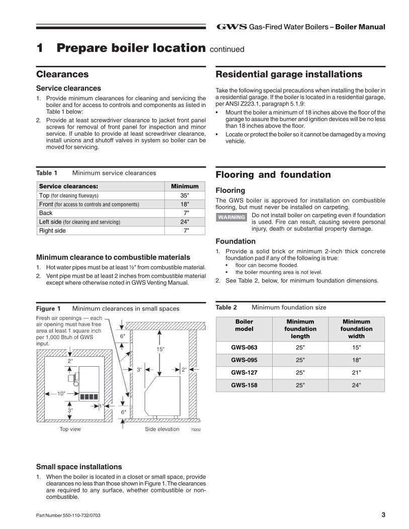
Small space installations1. When the boiler is located in a closet or small space, provide
clearances no less than those shown in Figure 1. The clearancesare required to any surface, whether combustible or non-combustible.
Table 2 Minimum foundation size
Boilermodel
Minimumfoundation
length
Minimumfoundation
width
GWS-063 25" 15"
GWS-095 25" 18"
GWS-127 25" 21"
GWS-158 25" 24"
Figure 1 Minimum clearances in small spaces
Service clearances: Minimum
Top (for cleaning flueways) 35"Front (for access to controls and components) 18"Back 7"
Left side (for cleaning and servicing) 24"Right side 7"
Table 1 Minimum service clearances
GWS Gas-Fired Water Boilers – Boiler Manual
4 Part Number 550-110-732/0703
1 Prepare boiler location continued
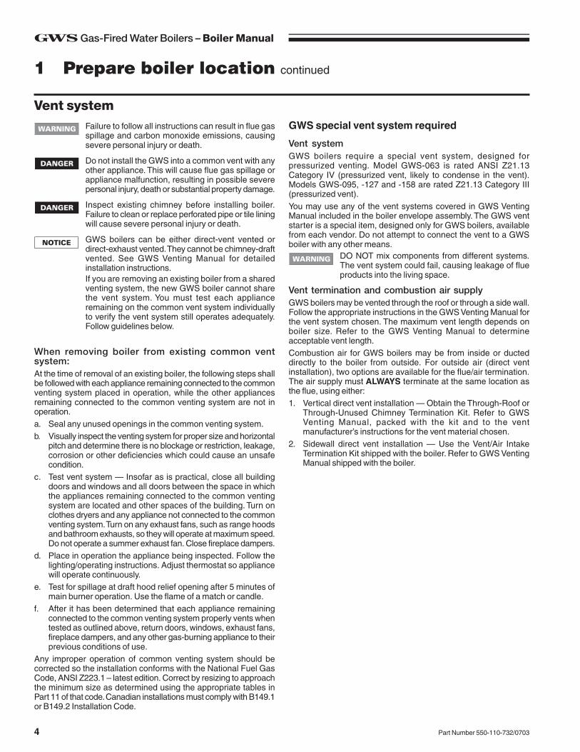
GWS special vent system required
Vent systemGWS boilers require a special vent system, designed forpressurized venting. Model GWS-063 is rated ANSI Z21.13Category IV (pressurized vent, likely to condense in the vent).Models GWS-095, -127 and -158 are rated Z21.13 Category III(pressurized vent).You may use any of the vent systems covered in GWS VentingManual included in the boiler envelope assembly. The GWS ventstarter is a special item, designed only for GWS boilers, availablefrom each vendor. Do not attempt to connect the vent to a GWSboiler with any other means.
DO NOT mix components from different systems.The vent system could fail, causing leakage of flueproducts into the living space.
Vent termination and combustion air supplyGWS boilers may be vented through the roof or through a side wall.Follow the appropriate instructions in the GWS Venting Manual forthe vent system chosen. The maximum vent length depends onboiler size. Refer to the GWS Venting Manual to determineacceptable vent length.Combustion air for GWS boilers may be from inside or ducteddirectly to the boiler from outside. For outside air (direct ventinstallation), two options are available for the flue/air termination.The air supply must ALWAYS terminate at the same location asthe flue, using either:1. Vertical direct vent installation — Obtain the Through-Roof or
Through-Unused Chimney Termination Kit. Refer to GWSVenting Manual, packed with the kit and to the ventmanufacturer’s instructions for the vent material chosen.
2. Sidewall direct vent installation — Use the Vent/Air IntakeTermination Kit shipped with the boiler. Refer to GWS VentingManual shipped with the boiler.
Failure to follow all instructions can result in flue gasspillage and carbon monoxide emissions, causingsevere personal injury or death.
Do not install the GWS into a common vent with anyother appliance. This will cause flue gas spillage orappliance malfunction, resulting in possible severepersonal injury, death or substantial property damage.
Inspect existing chimney before installing boiler.Failure to clean or replace perforated pipe or tile liningwill cause severe personal injury or death.
GWS boilers can be either direct-vent vented ordirect-exhaust vented. They cannot be chimney-draftvented. See GWS Venting Manual for detailedinstallation instructions.If you are removing an existing boiler from a sharedventing system, the new GWS boiler cannot sharethe vent system. You must test each applianceremaining on the common vent system individuallyto verify the vent system still operates adequately.Follow guidelines below.
When removing boiler from existing common ventsystem:At the time of removal of an existing boiler, the following steps shallbe followed with each appliance remaining connected to the commonventing system placed in operation, while the other appliancesremaining connected to the common venting system are not inoperation.a. Seal any unused openings in the common venting system.b. Visually inspect the venting system for proper size and horizontal
pitch and determine there is no blockage or restriction, leakage,corrosion or other deficiencies which could cause an unsafecondition.
c. Test vent system — Insofar as is practical, close all buildingdoors and windows and all doors between the space in whichthe appliances remaining connected to the common ventingsystem are located and other spaces of the building. Turn onclothes dryers and any appliance not connected to the commonventing system. Turn on any exhaust fans, such as range hoodsand bathroom exhausts, so they will operate at maximum speed.Do not operate a summer exhaust fan. Close fireplace dampers.
d. Place in operation the appliance being inspected. Follow thelighting/operating instructions. Adjust thermostat so appliancewill operate continuously.
e. Test for spillage at draft hood relief opening after 5 minutes ofmain burner operation. Use the flame of a match or candle.
f. After it has been determined that each appliance remainingconnected to the common venting system properly vents whentested as outlined above, return doors, windows, exhaust fans,fireplace dampers, and any other gas-burning appliance to theirprevious conditions of use.
Any improper operation of common venting system should becorrected so the installation conforms with the National Fuel GasCode, ANSI Z223.1 – latest edition. Correct by resizing to approachthe minimum size as determined using the appropriate tables inPart 11 of that code. Canadian installations must comply with B149.1or B149.2 Installation Code.
Vent system
5Part Number 550-110-732/0703
GWS Gas-Fired Water Boilers – Boiler Manual
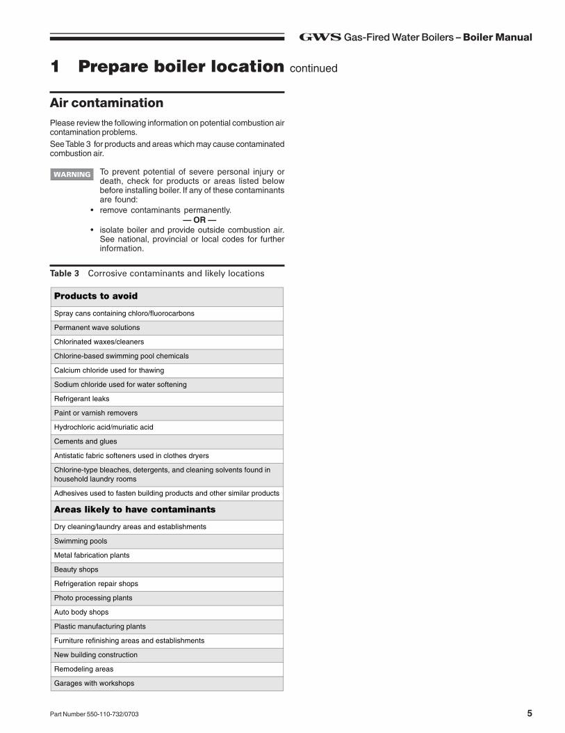
Table 3 Corrosive contaminants and likely locations
To prevent potential of severe personal injury ordeath, check for products or areas listed belowbefore installing boiler. If any of these contaminantsare found:
• remove contaminants permanently.— OR —
• isolate boiler and provide outside combustion air.See national, provincial or local codes for furtherinformation.
Please review the following information on potential combustion aircontamination problems.See Table 3 for products and areas which may cause contaminatedcombustion air.
Air contamination
Products to avoid
Spray cans containing chloro/fluorocarbons
Permanent wave solutions
Chlorinated waxes/cleaners
Chlorine-based swimming pool chemicals
Calcium chloride used for thawing
Sodium chloride used for water softening
Refrigerant leaks
Paint or varnish removers
Hydrochloric acid/muriatic acid
Cements and glues
Antistatic fabric softeners used in clothes dryers
Chlorine-type bleaches, detergents, and cleaning solvents found in household laundry rooms
Adhesives used to fasten building products and other similar products
Areas likely to have contaminants
Dry cleaning/laundry areas and establishments
Swimming pools
Metal fabrication plants
Beauty shops
Refrigeration repair shops
Photo processing plants
Auto body shops
Plastic manufacturing plants
Furniture refinishing areas and establishments
New building construction
Remodeling areas
Garages with workshops
1 Prepare boiler location continued
GWS Gas-Fired Water Boilers – Boiler Manual
6 Part Number 550-110-732/0703
Air openingsUsing inside air — direct exhaust ventingThe GWS boiler can use inside air if no contaminants are presentin the boiler space. If contaminants are likely to be present, installthe GWS boiler as a direct vent appliance, using the appropriateinstructions in the GWS Venting Manual and the instructions in thismanual.
Using outside air — direct ventingCombustion air can be ducted directly from outside to the GWSboiler air intake fitting. This method is defined as direct vent (alsoreferred to as sealed combustion). Refer to the appropriateinstructions in the GWS Venting Manual and the instructions in thismanual. Two options are available: sidewall or vertical direct vent.Each requires a special vent component kit.
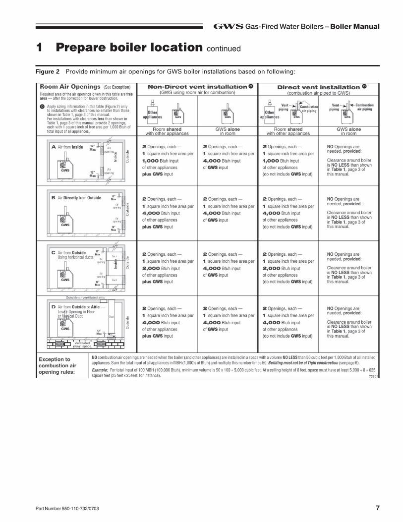
Sizing air openingsAir openings provide for ventilation (as well as combustion air) toprevent overheating of the boiler controls and boiler space. Air isalso needed for other appliances located in the same space.Use Figure 2, page 7, selecting the appropriate installation conditions.Note that the sizing given in Figure 2 applies only to GWSinstallations with clearances no smaller than shown in Table 1, page3 of this manual. For smaller clearances, regardless of how the airopenings are arranged, two openings providing free area of 1 squareinch per 1,000 Btuh input of all appliances in the space are required.
Air openings must be sized to handle all appliancesand air movers (exhaust fans, etc.) using the airsupply.
The sizing given in Figure 2 is based on the National Fuel GasCode, ANSI Z223.1, allowing adequate air opening for gravity-ventedgas appliances. The air openings recommended in Figure 2 willallow adequate ventilation and combustion air provided the boilerroom is not subjected to negative pressure due to exhaust fans orother mechanical ventilation devices. Refer to the National FuelGas Code for dealing with other conditions.
Louver allowanceThe free area of openings means the area after reduction for anyinstalled louvers or grilles. Be sure to consider this reduction whensizing the air openings.
Special considerations
Tight constructionANSI Z223.1 defines unusually tight construction where:a. Walls and ceilings exposed to the outside atmosphere have a
continuous water vapor retarder with a rating of 1 perm or lesswith openings gasketed, and . . .
b. Weather-stripping has been added on openable windows anddoors, and . . .
c. Caulking or sealants are applied to areas such as joints aroundwindows and door frames, between sole plates and floors,between wall-ceiling joints, between wall panels, at penetrationsfor plumbing, electrical, and gas lines, and in other openings.
For buildings with such construction, provide air openings into thebuilding from outside, sized per the appropriate case in Figure 2.
Exhaust fans and air moversThe appliance space must never be under a negative pressure,unless the appliances are installed as direct vent. Always provideair openings sized not only to the dimensions required for the firingrate of all appliances, but also to handle the air movement rate ofthe exhaust fans or air movers using air from the building or space.
Motorized air dampersIf the air openings are fitted with motorized dampers, electricallyinterlock the damper to:• Prevent the boiler from firing if the damper is not fully open.• Shut the boiler down should the damper close during boiler
operation.To accomplish this interlock, wire an isolated contact (proving thedamper open) in series with the thermostat input to the boiler. Theboiler will not start if this contact is open, and will shut down shouldit open during operation.
1 Prepare boiler location continued
7Part Number 550-110-732/0703
GWS Gas-Fired Water Boilers – Boiler Manual
Figure 2 Provide minimum air openings for GWS boiler installations based on following:
1 Prepare boiler location continued
GWS Gas-Fired Water Boilers – Boiler Manual
8 Part Number 550-110-732/0703
Perform hydrostatic pressure testPressure test boiler before attaching water or gas piping or electricalsupply (except as noted below).
Prepare boiler for test1. Remove the shipping nipple (from GWS supply tapping) and
remove the boiler relief valve. Temporarily plug the relief valvetapping with a ¾" NPT pipe plug.
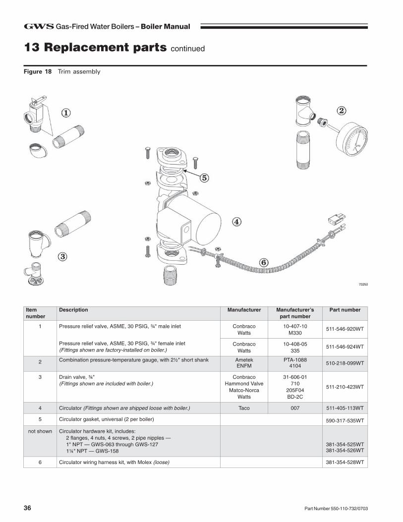
2. Remove 1¼" nipple, reducing tee and drain valve fromaccessory bag. Install in boiler return connection as shown onin Figure 18, item 3, page 36. Install circulator on either thereturn or supply.
3. Remove 1¼" nipple, 1¼" tee, bushing and pressure/temperaturegauge from accessory bag. Pipe to boiler supply connection asshown in Figure 18, item 2, page 36. (Use pipe dope sparingly.)
4. Connect a hose to boiler drain valve, the other end connectedto a fresh water supply. Make sure hose can also be used todrain boiler after test.
5. Connect a nipple and shutoff valve to system supply connectionon the 1¼" tee. This valve will be used to bleed air during the fill.(Valve and nipple are not included with boiler.)
6. Connect a nipple and shutoff valve to system return connection(at circulator flange if circulator installed on return). This valvewill be used to bleed air during the fill. (Valve and nipple are notincluded with boiler.)
Fill and pressure test1. Open the shutoff valves you installed on supply and return
connections.
Pressure test2. Slowly open boiler drain valve and fresh water supply to fill
boiler with water.3. When water flows from shutoff valves, close boiler drain valve.4. Close shutoff valves.5. Slowly reopen boiler drain valve until test pressure of not more
than 45 psi is reached on the pressure/temperature gauge.6. Test at no more than 45 psi for no more than 10 minutes.
Do not leave boiler unattended. A cold water fill couldexpand and cause excessive pressure, resulting insevere personal injury, death or substantial propertydamage.
7. Make sure constant gauge pressure has been maintainedthroughout test. Check for leaks. Repair if found.
Leaks must be repaired at once. Failure to do so candamage boiler, resulting in substantial propertydamage.Do not use petroleum-based cleaning or sealingcompounds in boiler system. Severe damage to boilerwill occur, resulting in substantial property damage.
Drain and remove fittings1. Disconnect fill water hose from water source.2. Drain boiler at drain valve or out hose, whichever provides best
access to drain. Remove hose after draining if used to drainboiler.
3. Remove nipples and valves unless they will remain for use inthe system piping.
4. Remove plug from relief valve tapping. See Section 3, page 9,to replace relief valve.
2 Prepare boiler
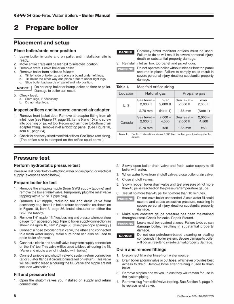
Table 4 Manifold orifice sizing
Place boiler/crate near position1. Leave boiler in crate and on pallet until installation site is
ready.2. Move entire crate and pallet next to selected location.3. Remove crate. Leave boiler on pallet.4. Remove boiler from pallet as follows:
a. Tilt left side of boiler up and place a board under left legs.b. Tilt boiler the other way and place a board under right legs.c. Slide boiler backwards off pallet and into position.
Do not drop boiler or bump jacket on floor or pallet.Damage to boiler can result.
5. Check level.a. Shim legs, if necessary.b. Do not alter legs.
Inspect orifices and burners; connect air adapter1. Remove front jacket door. Remove air adapter fitting from air
inlet hose (see Figure 17, page 35, items 9 and 10) and screwinto opening on jacket top. Reconnect air hose to bottom of airadapter fitting. Remove inlet air box top panel. (See Figure 16,item 13, page 34).
2. Check for correctly-sized manifold orifices. See Table 4 for sizing.(The orifice size is stamped on the orifice spud barrel.)
Placement and setupCorrectly-sized manifold orifices must be used.Failure to do so will result in severe personal injury,death or substantial property damage.
3. Reinstall inlet air box top panel and jacket door.Do not operate boiler without inlet air box top panelsecured in place. Failure to comply could result insevere personal injury, death or substantial propertydamage.
9Part Number 550-110-732/0703
GWS Gas-Fired Water Boilers – Boiler Manual
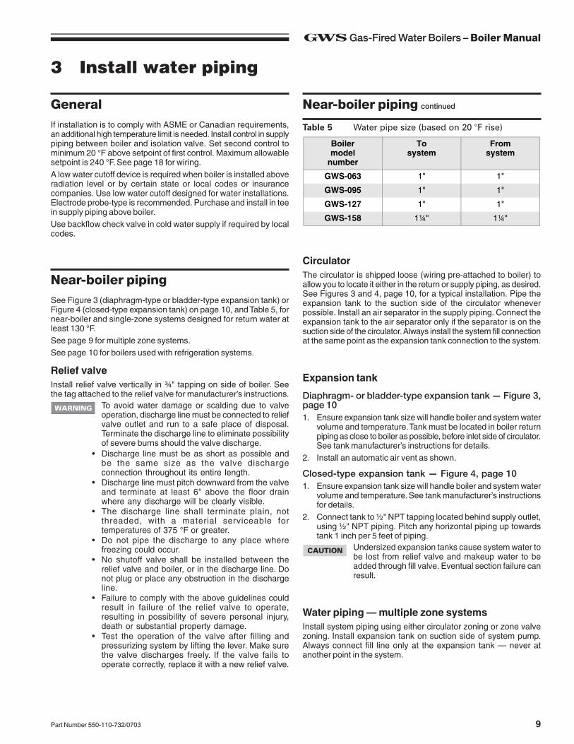
Table 5 Water pipe size (based on 20 °F rise)
3 Install water piping
Expansion tank
Diaphragm- or bladder-type expansion tank — Figure 3,page 101. Ensure expansion tank size will handle boiler and system water
volume and temperature. Tank must be located in boiler returnpiping as close to boiler as possible, before inlet side of circulator.See tank manufacturer’s instructions for details.
2. Install an automatic air vent as shown.
Closed-type expansion tank — Figure 4, page 101. Ensure expansion tank size will handle boiler and system water
volume and temperature. See tank manufacturer’s instructionsfor details.
2. Connect tank to ½" NPT tapping located behind supply outlet,using ½" NPT piping. Pitch any horizontal piping up towardstank 1 inch per 5 feet of piping.
Undersized expansion tanks cause system water tobe lost from relief valve and makeup water to beadded through fill valve. Eventual section failure canresult.
GeneralIf installation is to comply with ASME or Canadian requirements,an additional high temperature limit is needed. Install control in supplypiping between boiler and isolation valve. Set second control tominimum 20 °F above setpoint of first control. Maximum allowablesetpoint is 240 °F. See page 18 for wiring.A low water cutoff device is required when boiler is installed aboveradiation level or by certain state or local codes or insurancecompanies. Use low water cutoff designed for water installations.Electrode probe-type is recommended. Purchase and install in teein supply piping above boiler.Use backflow check valve in cold water supply if required by localcodes.
See Figure 3 (diaphragm-type or bladder-type expansion tank) orFigure 4 (closed-type expansion tank) on page 10, and Table 5, fornear-boiler and single-zone systems designed for return water atleast 130 °F.See page 9 for multiple zone systems.See page 10 for boilers used with refrigeration systems.
Near-boiler piping
Water piping — multiple zone systemsInstall system piping using either circulator zoning or zone valvezoning. Install expansion tank on suction side of system pump.Always connect fill line only at the expansion tank — never atanother point in the system.
Relief valveInstall relief valve vertically in ¾" tapping on side of boiler. Seethe tag attached to the relief valve for manufacturer’s instructions.
To avoid water damage or scalding due to valveoperation, discharge line must be connected to reliefvalve outlet and run to a safe place of disposal.Terminate the discharge line to eliminate possibilityof severe burns should the valve discharge.
• Discharge line must be as short as possible andbe the same size as the valve dischargeconnection throughout its entire length.
• Discharge line must pitch downward from the valveand terminate at least 6" above the floor drainwhere any discharge will be clearly visible.
• The discharge line shall terminate plain, notthreaded, with a material serviceable fortemperatures of 375 °F or greater.
• Do not pipe the discharge to any place wherefreezing could occur.
• No shutoff valve shall be installed between therelief valve and boiler, or in the discharge line. Donot plug or place any obstruction in the dischargeline.
• Failure to comply with the above guidelines couldresult in failure of the relief valve to operate,resulting in possibility of severe personal injury,death or substantial property damage.
• Test the operation of the valve after filling andpressurizing system by lifting the lever. Make surethe valve discharges freely. If the valve fails tooperate correctly, replace it with a new relief valve.
CirculatorThe circulator is shipped loose (wiring pre-attached to boiler) toallow you to locate it either in the return or supply piping, as desired.See Figures 3 and 4, page 10, for a typical installation. Pipe theexpansion tank to the suction side of the circulator wheneverpossible. Install an air separator in the supply piping. Connect theexpansion tank to the air separator only if the separator is on thesuction side of the circulator. Always install the system fill connectionat the same point as the expansion tank connection to the system.
Near-boiler piping continued
Boilermodel
number
Tosystem
Fromsystem
GWS-063 1" 1"
GWS-095 1" 1"
GWS-127 1" 1"
GWS-158 1¼" 1¼"
GWS Gas-Fired Water Boilers – Boiler Manual
10 Part Number 550-110-732/0703
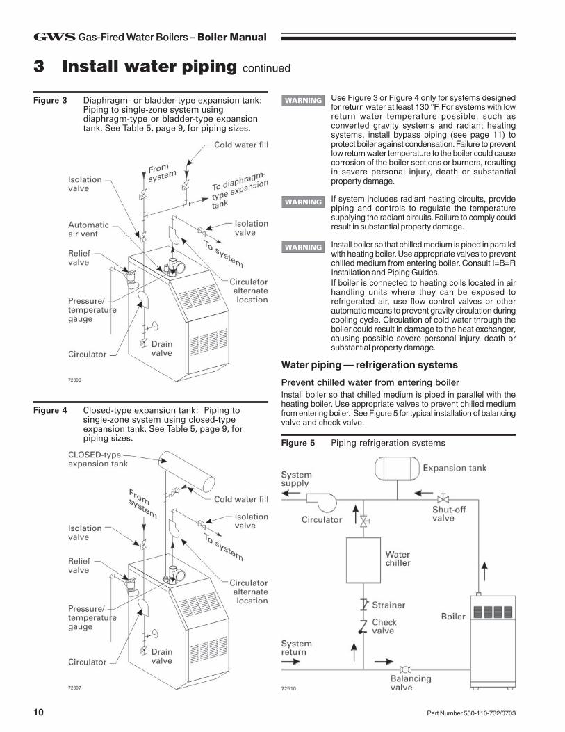
Figure 3 Diaphragm- or bladder-type expansion tank:Piping to single-zone system usingdiaphragm-type or bladder-type expansiontank. See Table 5, page 9, for piping sizes.
Figure 4 Closed-type expansion tank: Piping tosingle-zone system using closed-typeexpansion tank. See Table 5, page 9, forpiping sizes. Figure 5 Piping refrigeration systems
3 Install water piping continued
Water piping — refrigeration systems
Prevent chilled water from entering boilerInstall boiler so that chilled medium is piped in parallel with theheating boiler. Use appropriate valves to prevent chilled mediumfrom entering boiler. See Figure 5 for typical installation of balancingvalve and check valve.
Install boiler so that chilled medium is piped in parallelwith heating boiler. Use appropriate valves to preventchilled medium from entering boiler. Consult I=B=RInstallation and Piping Guides.If boiler is connected to heating coils located in airhandling units where they can be exposed torefrigerated air, use flow control valves or otherautomatic means to prevent gravity circulation duringcooling cycle. Circulation of cold water through theboiler could result in damage to the heat exchanger,causing possible severe personal injury, death orsubstantial property damage.
If system includes radiant heating circuits, providepiping and controls to regulate the temperaturesupplying the radiant circuits. Failure to comply couldresult in substantial property damage.
Use Figure 3 or Figure 4 only for systems designedfor return water at least 130 °F. For systems with lowreturn water temperature possible, such asconverted gravity systems and radiant heatingsystems, install bypass piping (see page 11) toprotect boiler against condensation. Failure to preventlow return water temperature to the boiler could causecorrosion of the boiler sections or burners, resultingin severe personal injury, death or substantialproperty damage.
11Part Number 550-110-732/0703
GWS Gas-Fired Water Boilers – Boiler Manual
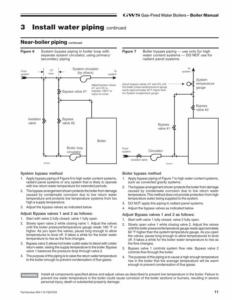
Figure 6 System bypass piping in boiler loop withseparate system circulator, using primary/secondary piping
Figure 7 Boiler bypass piping — use only for highwater content systems — DO NOT use forradiant panel systems
Near-boiler piping continued
Install all components specified above and adjust valves as described to prevent low temperature in the boiler. Failure toprevent low water temperature in the boiler could cause corrosion of the boiler sections or burners, resulting in severepersonal injury, death or substantial property damage.
3 Install water piping continued
System bypass method1. Apply bypass piping of Figure 6 to high water content systems,
radiant panel systems or any system that is likely to operatewith low return water temperature for extended periods.
2. The bypass arrangement shown protects the boiler from damagecaused by condensate corrosion due to low return watertemperature and protects low temperature systems from toohigh a supply temperature.
3. Adjust the bypass valves as indicated below.
Adjust Bypass valves 1 and 2 as follows:1. Start with valve 2 fully closed, valve 1 fully open.2. Slowly open valve 2 while closing valve 1. Adjust the valves
until the boiler pressure/temperature gauge reads 160 °F orhigher. As you open the valves, pause long enough to allowtemperatures to level off. It takes a while for the boiler watertemperature to rise as the flow changes.
3. Bypass valve 2 allows hot boiler outlet water to blend with colderreturn water, raising the supply temperature to the boiler. Bypassvalve 1 balances the pressure drop through valve 2.
4. The purpose of this piping is to raise the return water temperatureto the boiler enough to prevent condensation of flue gases.
Boiler bypass method1. Apply bypass piping of Figure 7 to high water content systems,
such as converted gravity systems.2. The bypass arrangement shown protects the boiler from damage
caused by condensate corrosion due to low return watertemperature. This method does not provide protection from hightemperature water being supplied to the system.
3. DO NOT apply this piping to radiant panel systems.4. Adjust the bypass valves as indicated below.
Adjust Bypass valves 1 and 2 as follows:1. Start with valve 1 fully closed, valve 2 fully open.2. Slowly open valve 1 while closing valve 2. Adjust the valves
until the boiler pressure/temperature gauge reads approximately60 °F higher than the system temperature gauge. As you openthe valves, pause long enough to allow temperatures to leveloff. It takes a while for the boiler water temperature to rise asthe flow changes.
3. Bypass valve 1 controls system flow rate. Bypass valve 2controls flow through the boiler.
4. The purpose of this piping is to cause a high enough temperaturerise in the boiler that the average temperature will be warmenough to prevent condensation of flue gases.
GWS Gas-Fired Water Boilers – Boiler Manual
12 Part Number 550-110-732/0703
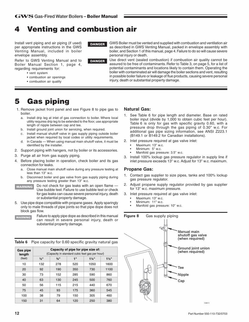
Figure 8 Gas supply piping
Table 6 Pipe capacity for 0.60 specific gravity natural gas
1. Remove jacket front panel and see Figure 8 to pipe gas toboiler.a. Install drip leg at inlet of gas connection to boiler. Where local
utility requires drip leg to be extended to the floor, use appropriatelength of nipple between cap and tee.
b. Install ground joint union for servicing, when required.c. Install manual shutoff valve in gas supply piping outside boiler
jacket when required by local codes or utility requirements.d. In Canada — When using manual main shutoff valve, it must be
identified by the installer.
2. Support piping with hangers, not by boiler or its accessories.3. Purge all air from gas supply piping.4. Before placing boiler in operation, check boiler and its gas
connection for leaks.a. Close manual main shutoff valve during any pressure testing at
less than 13" w.c.b. Disconnect boiler and gas valve from gas supply piping during
any pressure testing greater than 13" w.c.
Do not check for gas leaks with an open flame —Use bubble test. Failure to use bubble test or checkfor gas leaks can cause severe personal injury, deathor substantial property damage.
5. Use pipe dope compatible with propane gases. Apply sparinglyonly to male threads of pipe joints so that pipe dope does notblock gas flow.
Failure to apply pipe dope as described in this manualcan result in severe personal injury, death orsubstantial property damage.
Natural Gas:1. See Table 6 for pipe length and diameter. Base on rated
boiler input (divide by 1,000 to obtain cubic feet per hour).Table 6 is only for gas with specific gravity 0.60, with apressure drop through the gas piping of 0.30" w.c. Foradditional gas pipe sizing information, see ANSI Z223.1(B149.1 or B149.2 for Canadian installations).
2. Inlet pressure required at gas valve inlet:• Maximum: 13" w.c.• Minimum: 5" w.c.• Manifold gas pressure: 3.5" w.c.
3. Install 100% lockup gas pressure regulator in supply line ifinlet pressure exceeds 13" w.c. Adjust for 13" w.c. maximum.
Propane Gas:1. Contact gas supplier to size pipes, tanks and 100% lockup
gas pressure regulator.2. Adjust propane supply regulator provided by gas supplier
for 13" w.c. maximum pressure.3. Inlet pressure required at gas valve inlet:
Capacity of pipe for pipe size of:(Capacity in standard cubic feet gas per hour)
½" ¾" 1" 1¼" 1½"
10 132 278 520 1050 1600
20 92 190 350 730 1100
30 73 152 285 590 860
40 63 130 245 500 760
50 56 115 215 440 670
75 45 93 175 360 545
100 38 79 150 305 460
150 31 64 120 250 380
4 Venting and combustion air
GWS Boiler must be vented and supplied with combustion and ventilation airas described in GWS Venting Manual, packed in envelope assembly withboiler, and Section 1 of this manual, page 4. Failure to do so will cause severepersonal injury or death.Use direct vent (sealed combustion) if combustion air quality cannot beassured to be free of contaminants. Refer to Table 3, on page 5, for a list ofpotential contaminants and locations likely to contain them. Operating theboiler with contaminated air will damage the boiler sections and vent, resultingin possible boiler failure or leakage of flue products, causing severe personalinjury, death or substantial property damage.
Install vent piping and air piping (if used)per appropriate instructions in the GWSVenting Manual, included in boilerenvelope assembly.Refer to GWS Venting Manual and toBoiler Manual Section 1, page 4,regarding requirements for:
• vent system• combustion air openings• combustion air quality
5 Gas piping
13Part Number 550-110-732/0703
GWS Gas-Fired Water Boilers – Boiler Manual
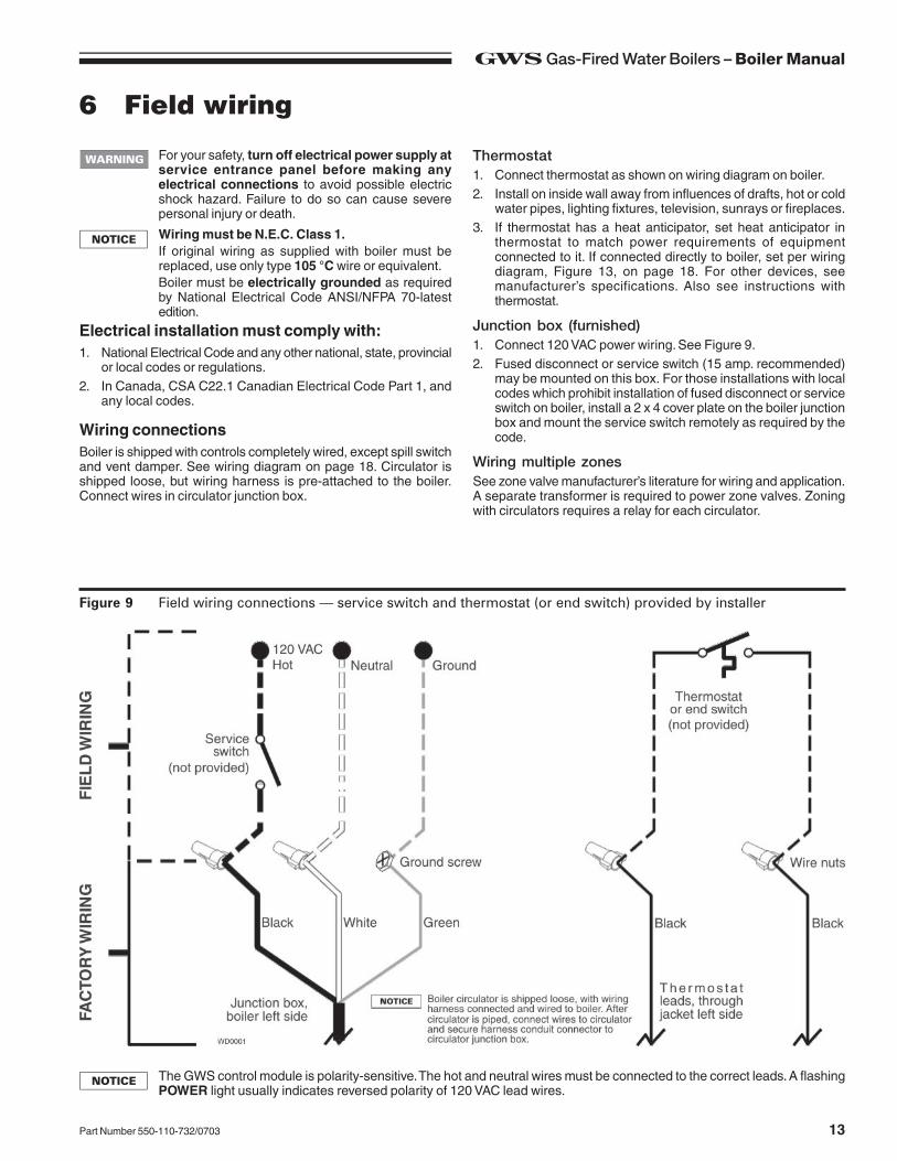
For your safety, turn off electrical power supply atservice entrance panel before making anyelectrical connections to avoid possible electricshock hazard. Failure to do so can cause severepersonal injury or death.
Figure 9 Field wiring connections — service switch and thermostat (or end switch) provided by installer
6 Field wiring
Thermostat1. Connect thermostat as shown on wiring diagram on boiler.2. Install on inside wall away from influences of drafts, hot or cold
water pipes, lighting fixtures, television, sunrays or fireplaces.3. If thermostat has a heat anticipator, set heat anticipator in
thermostat to match power requirements of equipmentconnected to it. If connected directly to boiler, set per wiringdiagram, Figure 13, on page 18. For other devices, seemanufacturer’s specifications. Also see instructions withthermostat.
Junction box (furnished)1. Connect 120 VAC power wiring. See Figure 9.2. Fused disconnect or service switch (15 amp. recommended)
may be mounted on this box. For those installations with localcodes which prohibit installation of fused disconnect or serviceswitch on boiler, install a 2 x 4 cover plate on the boiler junctionbox and mount the service switch remotely as required by thecode.
Wiring multiple zonesSee zone valve manufacturer’s literature for wiring and application.A separate transformer is required to power zone valves. Zoningwith circulators requires a relay for each circulator.
The GWS control module is polarity-sensitive. The hot and neutral wires must be connected to the correct leads. A flashingPOWER light usually indicates reversed polarity of 120 VAC lead wires.
Wiring must be N.E.C. Class 1.If original wiring as supplied with boiler must bereplaced, use only type 105 °C wire or equivalent.Boiler must be electrically grounded as requiredby National Electrical Code ANSI/NFPA 70-latestedition.
Electrical installation must comply with:1. National Electrical Code and any other national, state, provincial
or local codes or regulations.2. In Canada, CSA C22.1 Canadian Electrical Code Part 1, and
any local codes.
Wiring connectionsBoiler is shipped with controls completely wired, except spill switchand vent damper. See wiring diagram on page 18. Circulator isshipped loose, but wiring harness is pre-attached to the boiler.Connect wires in circulator junction box.
GWS Gas-Fired Water Boilers – Boiler Manual
14 Part Number 550-110-732/0703
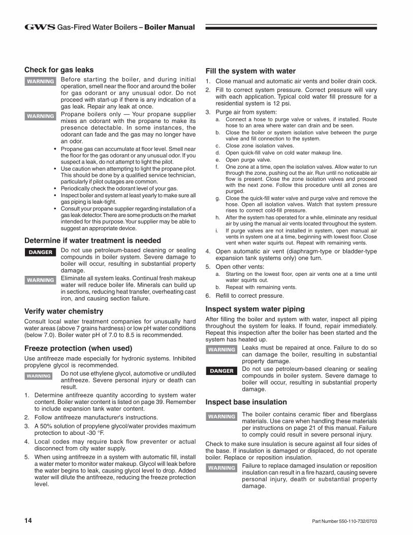
Check for gas leaksBefore starting the boiler, and during initialoperation, smell near the floor and around the boilerfor gas odorant or any unusual odor. Do notproceed with start-up if there is any indication of agas leak. Repair any leak at once.Propane boilers only — Your propane suppliermixes an odorant with the propane to make itspresence detectable. In some instances, theodorant can fade and the gas may no longer havean odor.
• Propane gas can accumulate at floor level. Smell nearthe floor for the gas odorant or any unusual odor. If yoususpect a leak, do not attempt to light the pilot.
• Use caution when attempting to light the propane pilot.This should be done by a qualified service technician,particularly if pilot outages are common.
• Periodically check the odorant level of your gas.• Inspect boiler and system at least yearly to make sure all
gas piping is leak-tight.• Consult your propane supplier regarding installation of a
gas leak detector. There are some products on the marketintended for this purpose. Your supplier may be able tosuggest an appropriate device.
Determine if water treatment is neededDo not use petroleum-based cleaning or sealingcompounds in boiler system. Severe damage toboiler will occur, resulting in substantial propertydamage.Eliminate all system leaks. Continual fresh makeupwater will reduce boiler life. Minerals can build upin sections, reducing heat transfer, overheating castiron, and causing section failure.
Verify water chemistryConsult local water treatment companies for unusually hardwater areas (above 7 grains hardness) or low pH water conditions(below 7.0). Boiler water pH of 7.0 to 8.5 is recommended.
Freeze protection (when used)Use antifreeze made especially for hydronic systems. Inhibitedpropylene glycol is recommended.
Do not use ethylene glycol, automotive or undilutedantifreeze. Severe personal injury or death canresult.
1. Determine antifreeze quantity according to system watercontent. Boiler water content is listed on page 39. Rememberto include expansion tank water content.
2. Follow antifreeze manufacturer's instructions.3. A 50% solution of propylene glycol/water provides maximum
protection to about -30 °F.4. Local codes may require back flow preventer or actual
disconnect from city water supply.5. When using antifreeze in a system with automatic fill, install
a water meter to monitor water makeup. Glycol will leak beforethe water begins to leak, causing glycol level to drop. Addedwater will dilute the antifreeze, reducing the freeze protectionlevel.
Fill the system with water1. Close manual and automatic air vents and boiler drain cock.2. Fill to correct system pressure. Correct pressure will vary
with each application. Typical cold water fill pressure for aresidential system is 12 psi.
3. Purge air from system:a. Connect a hose to purge valve or valves, if installed. Route
hose to an area where water can drain and be seen.b. Close the boiler or system isolation valve between the purge
valve and fill connection to the system.c. Close zone isolation valves.d. Open quick-fill valve on cold water makeup line.e. Open purge valve.f. One zone at a time, open the isolation valves. Allow water to run
through the zone, pushing out the air. Run until no noticeable airflow is present. Close the zone isolation valves and proceedwith the next zone. Follow this procedure until all zones arepurged.
g. Close the quick-fill water valve and purge valve and remove thehose. Open all isolation valves. Watch that system pressurerises to correct cold-fill pressure.
h. After the system has operated for a while, eliminate any residualair by using the manual air vents located throughout the system.
i. If purge valves are not installed in system, open manual airvents in system one at a time, beginning with lowest floor. Closevent when water squirts out. Repeat with remaining vents.
4. Open automatic air vent (diaphragm-type or bladder-typeexpansion tank systems only) one turn.
5. Open other vents:a. Starting on the lowest floor, open air vents one at a time until
water squirts out.b. Repeat with remaining vents.
6. Refill to correct pressure.
Inspect system water pipingAfter filling the boiler and system with water, inspect all pipingthroughout the system for leaks. If found, repair immediately.Repeat this inspection after the boiler has been started and thesystem has heated up.
Leaks must be repaired at once. Failure to do socan damage the boiler, resulting in substantialproperty damage.Do not use petroleum-based cleaning or sealingcompounds in boiler system. Severe damage toboiler will occur, resulting in substantial propertydamage.
Inspect base insulation
Check to make sure insulation is secure against all four sides ofthe base. If insulation is damaged or displaced, do not operateboiler. Replace or reposition insulation.
Failure to replace damaged insulation or repositioninsulation can result in a fire hazard, causing severepersonal injury, death or substantial propertydamage.
The boiler contains ceramic fiber and fiberglassmaterials. Use care when handling these materialsper instructions on page 21 of this manual. Failureto comply could result in severe personal injury.
15Part Number 550-110-732/0703
GWS Gas-Fired Water Boilers – Boiler Manual
7 Start-up continued
Check burner flame — Pilot burner
Proper pilot flame (see Figure 10):1. Blue flame.2. Inner cone engulfing pilot flame sensor.3. Pilot flame sensor glowing cherry red.
Improper pilot flame:1. Overfired — Large flame lifting or blowing past pilot flame sensor.2. Underfired — Small flame. Inner cone not engulfing pilot flame
sensor.3. Lack of primary air — Yellow flame tip.4. Incorrectly heated pilot flame sensor.
Check burner flames — Main burner
Proper main burner flame (see Figure 11):1. Yellow-orange streaks may appear (caused by dust).
Improper main burner flame:1. Overfired — Large flames.2. Underfired — Small flames.3. Lack of primary air — Yellow tipping on flames (sooting will
occur).
Figure 11 Typical main burner flame
Verify operation
Figure 10 Typical pilot burner flame
Operate boilerDO NOT proceed with boiler operation unlessboiler and system have been filled with water andall instructions and procedures of previous manualsections have been completed. Failure to do so couldresult in severe personal injury, death or substantialproperty damage. Before starting the boiler . . .
• Read manual Sections 8 and 9 and “Operatinginstructions”, page 19.
• Verify the boiler and system are full of water.• Verify the Start-up preparation procedures of this
section have been completed.
Start the boilerFollow “Operating instructions”, page 19. If boiler fails to start,see “If boiler doesn’t start . . . Check for:” on this page.
Check system and boilerEliminate all system leaks. Continual fresh makeupwater will reduce boiler life. Minerals can build up insections, reducing heat transfer, overheating cast iron,and causing section failure.If you discover evidence of any gas leak, shut downthe boiler at once. Find the leak source with bubbletest and repair immediately. Do not start boiler againuntil corrected. Failure to comply could result insevere personal injury, death or substantial propertydamage.Do not use petroleum-based cleaning or sealingcompounds in boiler system. Severe damage to boilerwill occur, resulting in substantial property damage.
1. Check system piping for leaks. If found, shut down boiler andrepair immediately.
2. Vent air from system using manual vents. Air in the systemwill interfere with circulation and cause heat distribution problemsand noise.
3. Inspect vent system thoroughly for signs of deterioration fromcorrosion, physical damage or sagging. Verify that masonrychimney liners are in good condition, with no obstructions, andthere are no openings into the chimney.
Venting system must be sealed gas-tight to preventflue gas spillage and carbon monoxide emissions.Failure to comply could result in severe personal injuryor death.
4. Check around the boiler for gas odor following the procedureof Section 7, page 14 of this manual.
5. Verify operation using procedures below. Perform checkoutprocedure in Section 8, page 16, and fill in the “Installation andservice certificate”.
If boiler doesn’t start . . . Check for:1. Loose connections, blown fuse or service switch off?2. High limit switch set below boiler water temperature?3. Thermostat set below room temperature?4. Gas not turned on at meter or boiler?5. Incoming gas pressure less than:
5" w.c. for natural gas? 11" w.c. for propane gas?6. If none of the above corrects the problem, see “Troubleshooting,”
page 25 of this manual.
GWS Gas-Fired Water Boilers – Boiler Manual
16 Part Number 550-110-732/0703
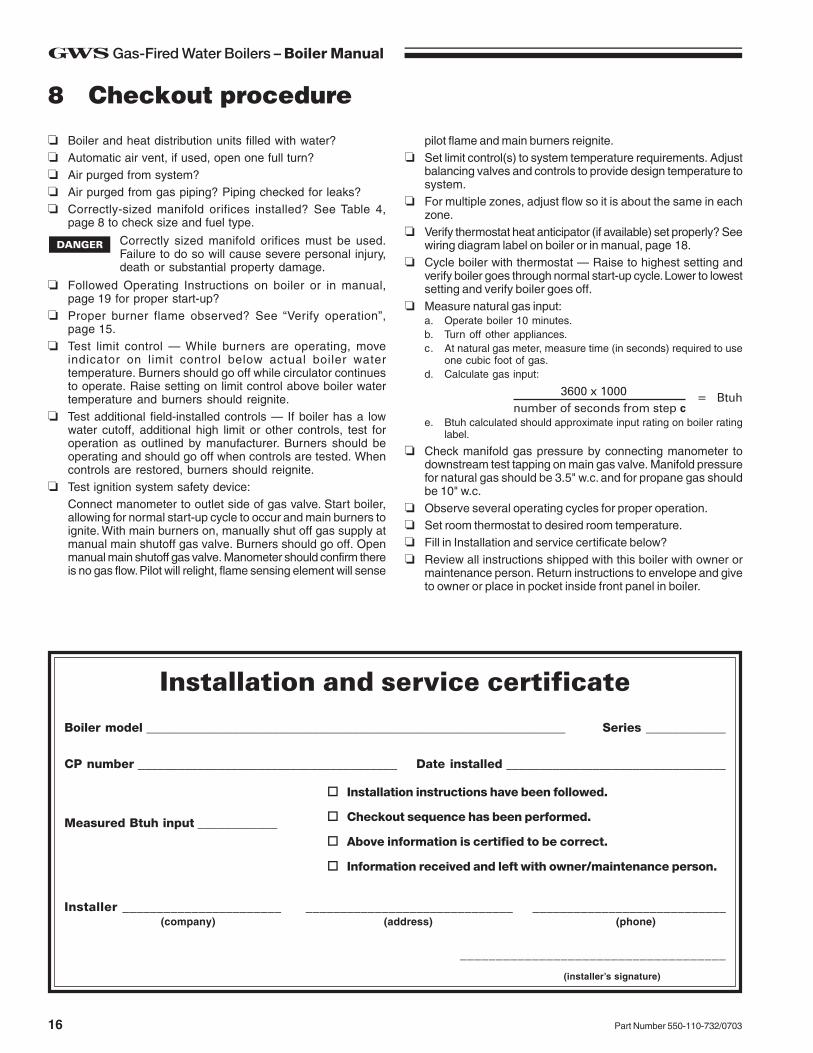
Boiler model _______________________________________________________________ Series ____________
CP number _______________________________________ Date installed _________________________________
❏ Boiler and heat distribution units filled with water?❏ Automatic air vent, if used, open one full turn?❏ Air purged from system?❏ Air purged from gas piping? Piping checked for leaks?❏ Correctly-sized manifold orifices installed? See Table 4,
page 8 to check size and fuel type.
Correctly sized manifold orifices must be used.Failure to do so will cause severe personal injury,death or substantial property damage.
❏ Followed Operating Instructions on boiler or in manual,page 19 for proper start-up?
❏ Proper burner flame observed? See “Verify operation”,page 15.
❏ Test limit control — While burners are operating, moveindicator on limit control below actual boiler watertemperature. Burners should go off while circulator continuesto operate. Raise setting on limit control above boiler watertemperature and burners should reignite.
❏ Test additional field-installed controls — If boiler has a lowwater cutoff, additional high limit or other controls, test foroperation as outlined by manufacturer. Burners should beoperating and should go off when controls are tested. Whencontrols are restored, burners should reignite.
❏ Test ignition system safety device:Connect manometer to outlet side of gas valve. Start boiler,allowing for normal start-up cycle to occur and main burners toignite. With main burners on, manually shut off gas supply atmanual main shutoff gas valve. Burners should go off. Openmanual main shutoff gas valve. Manometer should confirm thereis no gas flow. Pilot will relight, flame sensing element will sense
pilot flame and main burners reignite.❏ Set limit control(s) to system temperature requirements. Adjust
balancing valves and controls to provide design temperature tosystem.
❏ For multiple zones, adjust flow so it is about the same in eachzone.
❏ Verify thermostat heat anticipator (if available) set properly? Seewiring diagram label on boiler or in manual, page 18.
❏ Cycle boiler with thermostat — Raise to highest setting andverify boiler goes through normal start-up cycle. Lower to lowestsetting and verify boiler goes off.
❏ Measure natural gas input:a. Operate boiler 10 minutes.b. Turn off other appliances.c. At natural gas meter, measure time (in seconds) required to use
one cubic foot of gas.d. Calculate gas input:
3600 x 1000number of seconds from step c
= Btuh
e. Btuh calculated should approximate input rating on boiler ratinglabel.
❏ Check manifold gas pressure by connecting manometer todownstream test tapping on main gas valve. Manifold pressurefor natural gas should be 3.5" w.c. and for propane gas shouldbe 10" w.c.
❏ Observe several operating cycles for proper operation.❏ Set room thermostat to desired room temperature.❏ Fill in Installation and service certificate below?❏ Review all instructions shipped with this boiler with owner or
maintenance person. Return instructions to envelope and giveto owner or place in pocket inside front panel in boiler.
Installation instructions have been followed.
Checkout sequence has been performed.
Above information is certified to be correct.
Information received and left with owner/maintenance person.
Installation and service certificate
17Part Number 550-110-732/0703
GWS Gas-Fired Water Boilers – Boiler Manual
9 Sequence of operation
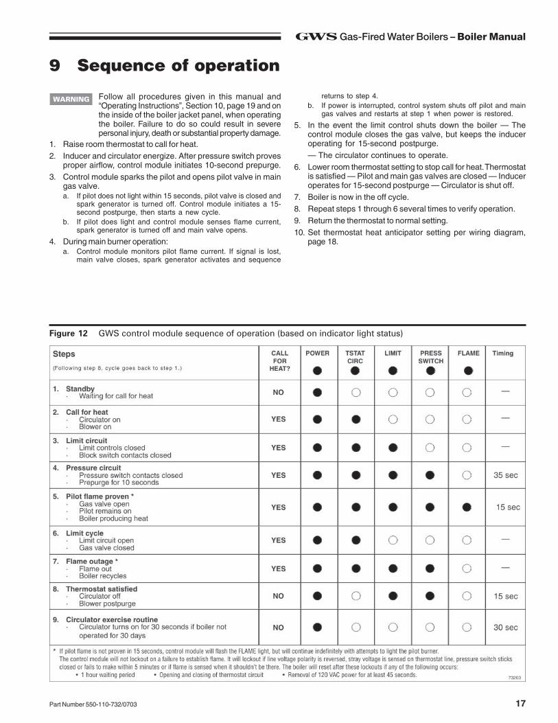
Figure 12 GWS control module sequence of operation (based on indicator light status)
Follow all procedures given in this manual and“Operating Instructions”, Section 10, page 19 and onthe inside of the boiler jacket panel, when operatingthe boiler. Failure to do so could result in severepersonal injury, death or substantial property damage.
1. Raise room thermostat to call for heat.2. Inducer and circulator energize. After pressure switch proves
proper airflow, control module initiates 10-second prepurge.3. Control module sparks the pilot and opens pilot valve in main
gas valve.a. If pilot does not light within 15 seconds, pilot valve is closed and
spark generator is turned off. Control module initiates a 15-second postpurge, then starts a new cycle.
b. If pilot does light and control module senses flame current,spark generator is turned off and main valve opens.
4. During main burner operation:a. Control module monitors pilot flame current. If signal is lost,
main valve closes, spark generator activates and sequence
returns to step 4.b. If power is interrupted, control system shuts off pilot and main
gas valves and restarts at step 1 when power is restored.
5. In the event the limit control shuts down the boiler — Thecontrol module closes the gas valve, but keeps the induceroperating for 15-second postpurge.— The circulator continues to operate.
6. Lower room thermostat setting to stop call for heat. Thermostatis satisfied — Pilot and main gas valves are closed — Induceroperates for 15-second postpurge — Circulator is shut off.
7. Boiler is now in the off cycle.8. Repeat steps 1 through 6 several times to verify operation.9. Return the thermostat to normal setting.10. Set thermostat heat anticipator setting per wiring diagram,
page 18.
GWS Gas-Fired Water Boilers – Boiler Manual
18 Part Number 550-110-732/0703
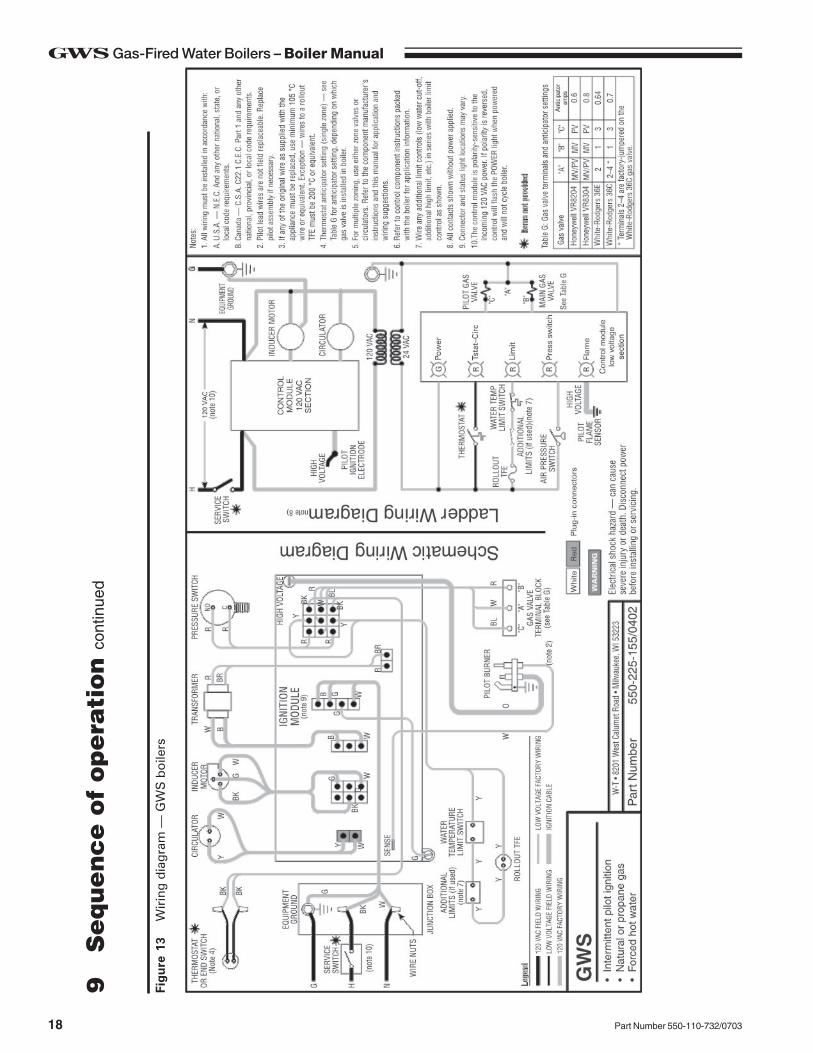
Figu
re 1
3W
irin
g d
iagr
am —
GW
S b
oile
rs
9S
equence o
f opera
tion c
ontin
ued
19Part Number 550-110-732/0703
GWS Gas-Fired Water Boilers – Boiler Manual
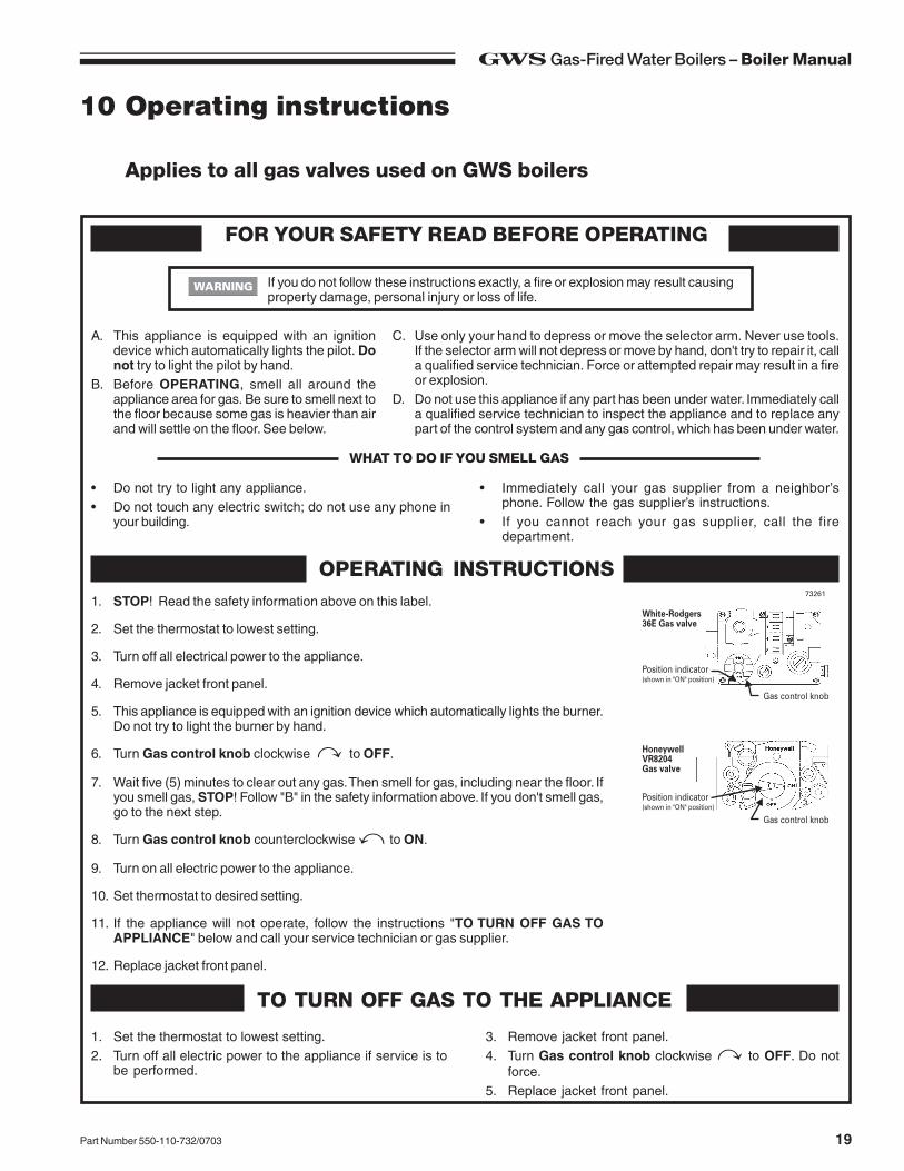
10 Operating instructions
Applies to all gas valves used on GWS boilers
FOR YOUR SAFETY READ BEFORE OPERATING
If you do not follow these instructions exactly, a fire or explosion may result causingproperty damage, personal injury or loss of life.
A. This appliance is equipped with an ignitiondevice which automatically lights the pilot. Donot try to light the pilot by hand.
B. Before OPERATING, smell all around theappliance area for gas. Be sure to smell next tothe floor because some gas is heavier than airand will settle on the floor. See below.
C. Use only your hand to depress or move the selector arm. Never use tools.If the selector arm will not depress or move by hand, don't try to repair it, calla qualified service technician. Force or attempted repair may result in a fireor explosion.
D. Do not use this appliance if any part has been under water. Immediately calla qualified service technician to inspect the appliance and to replace anypart of the control system and any gas control, which has been under water.
• Do not try to light any appliance.• Do not touch any electric switch; do not use any phone in
your building.
• Immediately call your gas supplier from a neighbor’sphone. Follow the gas supplier’s instructions.
• If you cannot reach your gas supplier, call the firedepartment.
WHAT TO DO IF YOU SMELL GAS
1. STOP! Read the safety information above on this label.
2. Set the thermostat to lowest setting.
3. Turn off all electrical power to the appliance.
4. Remove jacket front panel.
5. This appliance is equipped with an ignition device which automatically lights the burner.Do not try to light the burner by hand.
6. Turn Gas control knob clockwise to OFF.
7. Wait five (5) minutes to clear out any gas. Then smell for gas, including near the floor. Ifyou smell gas, STOP! Follow "B" in the safety information above. If you don't smell gas,go to the next step.
8. Turn Gas control knob counterclockwise to ON.
9. Turn on all electric power to the appliance.
10. Set thermostat to desired setting.
11. If the appliance will not operate, follow the instructions "TO TURN OFF GAS TOAPPLIANCE" below and call your service technician or gas supplier.
12. Replace jacket front panel.
OPERATING INSTRUCTIONS
TO TURN OFF GAS TO THE APPLIANCE
1. Set the thermostat to lowest setting.2. Turn off all electric power to the appliance if service is to
be performed.
3. Remove jacket front panel.4. Turn Gas control knob clockwise to OFF. Do not
force.5. Replace jacket front panel.
GWS Gas-Fired Water Boilers – Boiler Manual
20 Part Number 550-110-732/0703
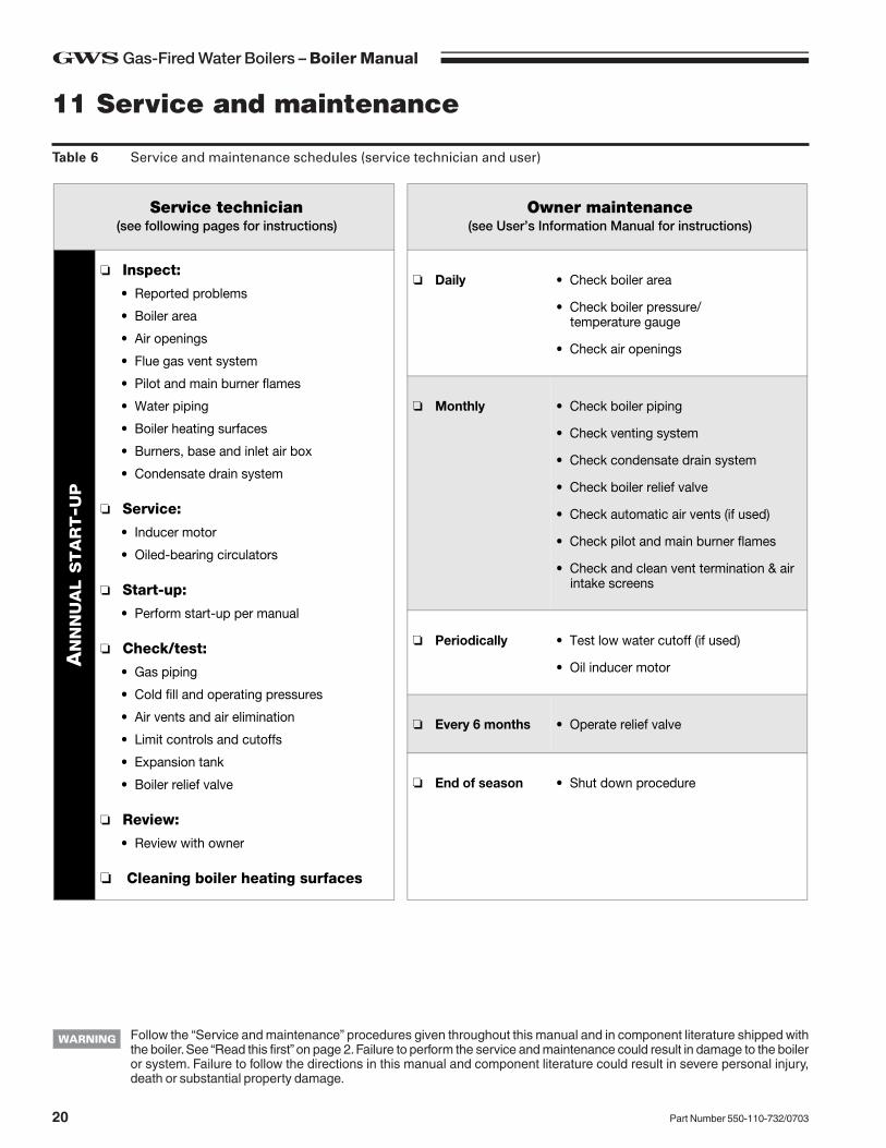
Follow the “Service and maintenance” procedures given throughout this manual and in component literature shipped withthe boiler. See “Read this first” on page 2. Failure to perform the service and maintenance could result in damage to the boileror system. Failure to follow the directions in this manual and component literature could result in severe personal injury,death or substantial property damage.
Table 6 Service and maintenance schedules (service technician and user)
11 Service and maintenance
Service technician(see following pages for instructions)
Owner maintenance(see User’s Information Manual for instructions)
AN
NN
UA
L S
TA
RT-U
P
❏ Inspect:
• Reported problems
• Boiler area
• Air openings
• Flue gas vent system
• Pilot and main burner flames
• Water piping
• Boiler heating surfaces
• Burners, base and inlet air box
• Condensate drain system
❏ Service:
• Inducer motor
• Oiled-bearing circulators
❏ Start-up:
• Perform start-up per manual
❏ Check/test:
• Gas piping
• Cold fill and operating pressures
• Air vents and air elimination
• Limit controls and cutoffs
• Expansion tank
• Boiler relief valve
❏ Review:
• Review with owner
❏ Cleaning boiler heating surfaces
❏ Daily • Check boiler area
• Check boiler pressure/temperature gauge
• Check air openings
❏ Monthly • Check boiler piping
• Check venting system
• Check condensate drain system
• Check boiler relief valve
• Check automatic air vents (if used)
• Check pilot and main burner flames
• Check and clean vent termination & air intake screens
❏ Periodically • Test low water cutoff (if used)
• Oil inducer motor
❏ Every 6 months • Operate relief valve
❏ End of season • Shut down procedure
21Part Number 550-110-732/0703
GWS Gas-Fired Water Boilers – Boiler Manual
Handling ceramic fiber and fiberglass materials
REMOVAL OF COMBUSTION CHAMBER LINING OR BASE PANELS
The combustion chamber lining or base insulation panels in this product contain ceramic fiber materials. Ceramicfibers can be converted to cristobalite in very high temperature applications. The International Agency for Researchon Cancer (IARC) has concluded, "Crystalline silica inhaled in the form of quartz or cristobalite from occupationalsources is carcinogenic to humans (Group 1).":
■ Avoid breathing dust and contact with skin and eyes.
• Use NIOSH certified dust respirator (N95). This type of respirator is based on the OSHA requirements forcristobalite at the time this document was written. Other types of respirators may be needed depending onthe job site conditions. Current NIOSH recommendations can be found on the NIOSH web site at http://www.cdc.gov/niosh/homepage.html. NIOSH approved respirators, manufacturers, and phone numbers arealso listed on this web site.
• Wear long-sleeved, loose fitting clothing, gloves, and eye protection.
■ Apply enough water to the combustion chamber lining or base insulation to prevent airborne dust.
■ Remove combustion chamber lining or base insulation from the boiler and place it in a plastic bag for disposal.
■ Wash potentially contaminated clothes separately from other clothing. Rinse clothes washer thoroughly.
NIOSH stated First Aid.■ Eye: Irrigate immediately
■ Breathing: Fresh air.
REMOVAL OF FIBERGLASS WOOL — OR —
INSTALLATION OF FIBERGLASS WOOL, COMBUSTION CHAMBER LINING OR BASE PANELS:
This product contains fiberglass jacket insulation and ceramic fiber materials in combustion chamber lining or basepanels in gas fired products. Airborne fibers from these materials have been listed by the State of California as apossible cause of cancer through inhalation.
■ Avoid breathing dust and contact with skin and eyes.
• Use NIOSH certified dust respirator (N95). This type of respirator is based on the OSHA requirements forfiberglass wool at the time this document was written. Other types of respirators may be needed dependingon the job site conditions. Current NIOSH recommendations can be found on the NIOSH web site at http://www.cdc.gov/niosh/homepage.html. NIOSH approved respirators, manufacturers, and phone numbers arealso listed on this web site.
• Wear long-sleeved, loose fitting clothing, gloves, and eye protection.
■ Operations such as sawing, blowing, tear out, and spraying may generate airborne fiber concentration requiringadditional protection.
■ Wash potentially contaminated clothes separately from other clothing. Rinse clothes washer thoroughly.
NIOSH stated First Aid.■ Eye: Irrigate immediately
■ Breathing: Fresh air.
11 Service and maintenance continued
GWS Gas-Fired Water Boilers – Boiler Manual
22 Part Number 550-110-732/0703
11 Service and maintenance continued
❏❏❏❏❏ Inspect . . . . . . . . . .Reported problemsInspect any problems reported by owner and correct beforeproceeding.
Boiler area1. Verify that boiler area is free of any combustible materials,
gasoline and other flammable vapors and liquids.2. Verify that boiler area (and air intake) is free of any of the
contaminants listed in Table 3 on page 5 of this manual. If any ofthese are present in the boiler intake air vicinity, they must beremoved. If they cannot be removed, install combustion air pipingto the boiler in accordance with national, provincial or localcodes.
Air openings1. Verify that combustion and ventilation air openings to the boiler
room and/or building are open and unobstructed. Checkoperation and wiring of automatic combustion air dampers, ifused.
2. Verify that boiler vent discharge and air intake are clean andfree of obstructions.
Flue gas vent system1. Visually inspect entire flue gas venting system for blockage,
deterioration or leakage. Repair any joints that show signs ofleakage in accordance with vent manufacturer’s instructions.
2. Verify that masonry chimneys are lined, lining is in goodcondition, and there are not openings into the chimney.
Failure to inspect for the above conditions and havethem repaired can result in severe personal injury ordeath.
Pilot and main burner flames1. Visually inspect pilot burner and main burner flames as directed
under Section 7, page 15 of this manual.
Water piping1. Check the boiler interior piping and all system piping for signs
of leaks.2. Repair any leaks before proceeding.
Electrical shock hazard — Turn off power to the boilerbefore any service operation on the boiler except asnoted otherwise in this instruction manual. Failure toturn off electrical power could result in electricalshock, causing severe personal injury or death.Do not use petroleum-based cleaning or sealingcompounds in boiler system. Severe damage to boilerwill occur, resulting in substantial property damage.Eliminate all system or boiler leaks. Continual freshmakeup water will reduce boiler life. Minerals canbuild up in sections, reducing heat transfer,overheating cast iron, and causing section failure.Leaking water may also cause severe propertydamage.
Boiler heating surfaces1. Disconnect the vent pipe at the boiler inducer outlet connection
after turning off power to the boiler.2. Use a bright light to inspect the flue pipe interior and inducer
interior.3. Inspect the boiler vent outlet area and heating surfaces by
looking through the opening.4. If the vent pipe or inducer interior show evidence of soot, follow
Cleaning boiler heating surfaces in this manual section to removethe flue collector and clean the boiler if necessary after closeinspection of boiler heating surfaces. If there is evidence of rustyscale deposits, check the water piping and control system tomake sure the boiler return water temperature is properlymaintained (per this manual).
5. Reconnect vent to inducer outlet and replace all boilercomponents before returning to service.
6. Check inside and around boiler for evidence of any leaks fromthe boiler. If found, locate source of leaks and repair.
Burners and base1. After turning off power to the boiler, remove the inlet air box top
panel (Figure 16, item 13, page 34).2. Inspect gasket (Figure 16, item 14, page 34).2. Inspect burners and all other components in the inlet air box
and boiler base.3. If burners must be cleaned, access the burner assembly by
first removing the burner baffle (Figure 16, item 4, page 34).Then remove the screws securing the burner tray to themanifold. Slide the burner tray out. Then brush and vacuum theburners thoroughly, making sure all ports are free of debris.
4. Inspect the base insulation. Verify that the insulation is intactand secure against all four sides of the base.
The boiler contains ceramic fiber and fiberglassmaterials. Use care when handling these materialsper instructions on page 21 of this manual. Failureto comply could result in severe personal injury.If insulation is damaged or displaced, do notoperate the boiler. Replace or reposition insulationas necessary. Failure to replace damaged insulationcan result in a fire hazard, causing severe personalinjury, death or substantial property damage.
5. Replace inlet air box top panel.Do not operate boiler without inlet air box top panelsecured in place. Failure to comply could result insevere personal injury, death or substantial propertydamage.
Condensate drain system1. If vent system is equipped with a condensate drain, check the
hose and connections for tightness.2. Verify the hose is unobstructed and in good condition and that
condensate can flow freely. Replace hose if necessary.
The boiler contains ceramic fiber and fiberglass materials. Use care when handling these materials per instructions onpage 21 of this manual. Failure to comply could result in severe personal injury.
23Part Number 550-110-732/0703
GWS Gas-Fired Water Boilers – Boiler Manual
Inducer motor1. With boiler power OFF, place a few drops of S.A.E. 20 motor oil
in each of the two motor oiling cups.Use only S.A.E. 20 motor oil to lubricate inducer motor.Do not universal household oils. Motor could bedamaged, resulting possible severe property damage.
Oiled-bearing circulators1. The circulator shipped with the GWS boiler is water-lubricated.
No oiling is required.2. Check other circulators in the system. Oil any circulators
requiring oil, following circulator manufacturer’s instructions.Over-oiling will damage the circulator.
❏❏❏❏❏ Service. . . . . . . . . .
❏❏❏❏❏ Start-up. . . . . . . . . .
1. Perform start-up procedures of Section 7, pages 14–15,including procedure to verify operation of burners on page 15.
2. Verify cold fill pressure is correct and that fill system is workingproperly.
3. Verify antifreeze level (if used) is at the right concentration andthat inhibitor level is correct.
4. Check gas piping, per manual Section 5, page 12, and section7, page 14, verifying no indications of leakage and all pipingand connections are in good condition.
5. Read “Operating instructions”, Section 10, page 19.6. Start the boiler following “Operating instructions”, Section 10,
page 19.
❏❏❏❏❏ Check/test. . . . . . . . . .Gas piping1. Sniff near floor and around boiler area for any indication of a
gas leak.2. Test gas piping using bubble test, per Section 5, page 12 of this
manual, if there is any indication of a leak.
Cold fill and operating pressures1. While the system is cold, note the pressure reading on the boiler
pressure/temperature gauge. Verify that cold fill pressure iscorrect.
2. Watch the pressure as the boiler and system heat up to ensurepressure rise is normal. Too high a rise would indicate awaterlogged or undersized expansion tank.
Air vents and air elimination1. Inspect automatic air vents (if used). Also inspect air separators
to ensure they are operational.
2. The cap must be unscrewed one turn to allow air to escape.3. If the air vent is leaking, remove cap and briefly push valve —
then release to clean the valve seat.4. Replace cap by twisting all the way onto valve and then
unscrewing one turn.
Limit controls and cutoffs1. Inspect and test the boiler limit control. Verify operation by turning
control set point below boiler temperature. Boiler should cycleoff. Return dial to original setting.
2. Inspect and test additional limit controls or low water cutoffsinstalled on system.
Expansion tank1. Expansion tanks provide space for water to move in an out as
the heating system water expands due to temperature increaseor contracts as the water cools. Tanks may be open, closed ordiaphragm- or bladder-type. See Section 3, page 9 of thismanual for suggested locations of expansion tanks and aireliminators.Open-type — located above highest radiator or baseboard unit,usually in the attic or closet. Has a gauge glass and overflowpipe to a drain.Closed-type — welded gas tight and located above boiler. Tankis partially filled with water, leaving an air cushion for expansion.• Make sure this type of tank is fitted with a tank fitting, such as
the B & G Tank-Trol or Taco Taco-Trol. This fitting reduces gravitycirculation of air-saturated tank water back to the system andprevents the air from bubbling up through the water as it returnsfrom the system.
• Do not use automatic air vents in systems with closed-typetanks. The air will escape from the system instead of returningto the tank. Eventually, the tank will waterlog and no longercontrol pressurization. The boiler relief valve will weep frequently.
Diaphragm- or bladder-type — welded gas tight with a rubbermembrane to separate the tank pressurizing air and the water.May be located at any point in the system, but most often foundnear the boiler.• Systems with this type of expansion tank require at least one
automatic air vent, preferably located on top of an air eliminator,as shown in examples in manual Section 3, page 10.
2. If relief valve has tended to weep frequently, the expansiontank may be waterlogged or undersized.Closed-type tank — tank is most likely waterlogged. Install atank fitting if not already installed. Then check fill level per fittingmanufacturer’s instructions. If fill level is correct, check tanksize against manufacturer’s instructions. Replace with a largertank if necessary.Diaphragm- or bladder-type — first, check tank size to be sureit is large enough for the system. If size is too small, addadditional tank(s) as necessary to provide sufficient expansion.If tank size is large enough, remove tank from system andcheck charge pressure (usually 12 psig for residentialapplications). If tank won’t hold pressure, membrane has beendamaged. Replace tank.
11 Service and maintenance continued
GWS Gas-Fired Water Boilers – Boiler Manual
24 Part Number 550-110-732/0703
❏❏❏❏❏ Check/test. . . . . . . . . . continued ❏❏❏❏❏ Review with owner1. Review the User’s Information Manual with the owner.2. Emphasize the need to perform the maintenance schedule
specified in the User’s Information Manual (and in this manualas well).
3. Remind the owner of the need to call in a licensed contractorshould the boiler or system exhibit any unusual behavior.
4. Remind the owner to follow the proper shutdown procedureand to schedule an annual start-up at the beginning of the nextheating season.
Boiler relief valve1. Inspect the relief valve and lift the lever to verify flow as in the
following warnings, excerpted from a relief valve manufacturer’swarning label. Before operating any relief valve, ensure that it ispiped with its discharge in a safe area to avoid severe scaldpotential. Read manual Section 3, page 9, before proceedingfurther.
Safety relief valves should be reinspected AT LEASTONCE EVERY THREE YEARS, by a licensed plumb-ing contractor or authorized inspection agency, toensure that the product has not been affected bycorrosive water conditions and to ensure that thevalve and discharge line have not been altered ortampered with illegally. Certain naturally occurringconditions may corrode the valve or its componentsover time, rendering the valve inoperative. Such con-ditions are not detectable unless the valve and itscomponents are physically removed and inspected.This inspection must only be conducted by a plumb-ing contractor or authorized inspection agency — notby the owner. Failure to reinspect the boiler relief valveas directed could result in unsafe pressure buildup,which can result in severe personal injury, death orsubstantial property damage.
2. After following the above warning directions, if the relief valveweeps or will not seat properly, replace the relief valve. Ensurethat the reason for relief valve weeping is the valve and notover-pressurization of the system due to expansion tankwaterlogging or undersizing.
Following installation, the valve lever must beoperated AT LEAST ONCE A YEAR to ensure thatwaterways are clear. Certain naturally occurringmineral deposits may adhere to the valve, renderingit inoperative. When manually operating the lever,water will discharge and precautions must be takento avoid contact with hot water and to avoid waterdamage. Before operating lever, check to see that adischarge line is connected to this valve directing theflow of hot water from the valve to a proper place ofdisposal otherwise severe personal injury may result.If no water flows, valve is inoperative. Shut downboiler until a new relief valve has been installed.
11 Service and maintenance continued
1. Shut down boiler:• Follow “To Turn Off Gas to Appliance” instructions on boiler and
“Operating instructions” page 19.• Do not drain boiler unless it will be exposed to freezing
temperatures. If using antifreeze in system, do not drain.
2. Follow shutdown procedure.3. Remove venting system connection to boiler.4. Remove top jacket panel. Turn back insulation.5. Remove collector box/transition assembly. Clean sealant
from assembly and sections.6. Remove radiation plates hanging between sections.7. Remove burners from base. Brush and vacuum burners to
remove all dust and lint. Verify that all burner ports are free ofdebris.
8. Place newspapers in base of boiler to collect soot.9. Clean between sections with wire flue brush.10. Remove newspaper and soot. Vacuum or brush base and
surrounding area.11. Reinstall radiation plates.12. Replace collector box/transition assembly. Seal with sealant.
Obtain gas-tight seal to prevent flue gas spillage and carbonmonoxide emissions, resulting in severe personal injury or death.
13. Replace insulation and jacket top panel.14. Start up boiler following Section 7, pages 14-15 of this manual
and the boiler “Operating instructions”, page 19. Excessivesooting indicates improper gas combustion. If found, check forproper combustion and make any necessary adjustments.
❏❏❏❏❏ Cleaning boiler heating surfacesThe boiler contains ceramic fiber and fiberglassmaterials. Use care when handling these materialsper instructions on page 21 of this manual. Failureto comply could result in severe personal injury.
25Part Number 550-110-732/0703
GWS Gas-Fired Water Boilers – Boiler Manual
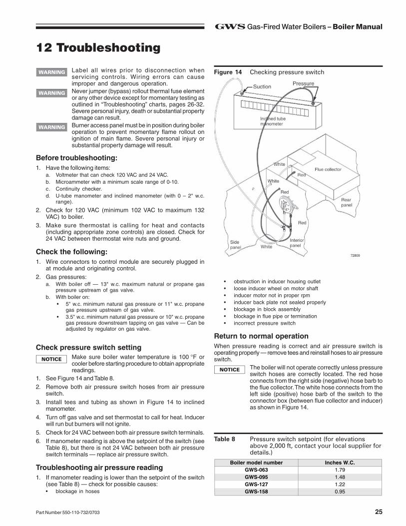
12 Troubleshooting
Figure 14 Checking pressure switchLabel all wires prior to disconnection whenservicing controls. Wiring errors can causeimproper and dangerous operation.Never jumper (bypass) rollout thermal fuse elementor any other device except for momentary testing asoutlined in “Troubleshooting” charts, pages 26-32.Severe personal injury, death or substantial propertydamage can result.Burner access panel must be in position during boileroperation to prevent momentary flame rollout onignition of main flame. Severe personal injury orsubstantial property damage will result.
Before troubleshooting:1. Have the following items:
a. Voltmeter that can check 120 VAC and 24 VAC.b. Microammeter with a minimum scale range of 0-10.c. Continuity checker.d. U-tube manometer and inclined manometer (with 0 – 2" w.c.
range).
2. Check for 120 VAC (minimum 102 VAC to maximum 132VAC) to boiler.
3. Make sure thermostat is calling for heat and contacts(including appropriate zone controls) are closed. Check for24 VAC between thermostat wire nuts and ground.
Check the following:1. Wire connectors to control module are securely plugged in
at module and originating control.2. Gas pressures:
a. With boiler off — 13" w.c. maximum natural or propane gaspressure upstream of gas valve.
b. With boiler on:• 5" w.c. minimum natural gas pressure or 11" w.c. propane
gas pressure upstream of gas valve.• 3.5" w.c. minimum natural gas pressure or 10" w.c. propane
gas pressure downstream tapping on gas valve — Can beadjusted by regulator on gas valve.
Check pressure switch settingMake sure boiler water temperature is 100 °F orcooler before starting procedure to obtain appropriatereadings.
1. See Figure 14 and Table 8.2. Remove both air pressure switch hoses from air pressure
switch.3. Install tees and tubing as shown in Figure 14 to inclined
manometer.4. Turn off gas valve and set thermostat to call for heat. Inducer
will run but burners will not ignite.5. Check for 24 VAC between both air pressure switch terminals.6. If manometer reading is above the setpoint of the switch (see
Table 8), but there is not 24 VAC between both air pressureswitch terminals — replace air pressure switch.
Troubleshooting air pressure reading1. If manometer reading is lower than the setpoint of the switch
(see Table 8) — check for possible causes:• blockage in hoses
• obstruction in inducer housing outlet• loose inducer wheel on motor shaft• inducer motor not in proper rpm• inducer back plate not sealed properly• blockage in block assembly• blockage in flue pipe or termination• incorrect pressure switch
Return to normal operationWhen pressure reading is correct and air pressure switch isoperating properly — remove tees and reinstall hoses to air pressureswitch.
The boiler will not operate correctly unless pressureswitch hoses are correctly located. The red hoseconnects from the right side (negative) hose barb tothe flue collector. The white hose connects from theleft side (positive) hose barb of the switch to theconnector box (between flue collector and inducer)as shown in Figure 14.
Table 8 Pressure switch setpoint (for elevationsabove 2,000 ft, contact your local supplier fordetails.)
Boiler model number Inches W.C.GWS-063 1.79GWS-095 1.48GWS-127 1.22GWS-158 0.95
The boiler contains ceramic fiber and fiberglass materials. Use care when handling these materials per instructions onpage 21 of this manual. Failure to comply could result in severe personal injury.
GWS Gas-Fired Water Boilers – Boiler Manual
34 Part Number 550-110-732/0703
Figure 16 Base assembly, manifold, orifices and burners
13 Replacement parts continued
The boiler contains ceramic fiber and fiberglass materials. Use care when handling these materials per instructions onpage 21 of this manual. Failure to comply could result in severe personal injury.
35Part Number 550-110-732/0703
GWS Gas-Fired Water Boilers – Boiler Manual
Figure 17 Jacket assembly
13 Replacement parts continued
The boiler contains ceramic fiber and fiberglass materials. Use care when handling these materials per instructions onpage 21 of this manual. Failure to comply could result in severe personal injury.
GWS Gas-Fired Water Boilers – Boiler Manual
36 Part Number 550-110-732/0703
Figure 18 Trim assembly
13 Replacement parts continued
37Part Number 550-110-732/0703
GWS Gas-Fired Water Boilers – Boiler Manual
Figure 19 Gas control assembly
13 Replacement parts continued
GWS Gas-Fired Water Boilers – Boiler Manual
38 Part Number 550-110-732/0703
Figure 20 Dimensional drawing — ALL DIMENSIONS IN INCHES
14 Dimensions
Boilermodelnumber
Supply tapping
(inches NPT)
Return tapping
(inches NPT)
Gasconnection size
Note 3(inches NPT)
Gasmanifold size
Note 3(inches NPT)
“A”Air inlet
pipe center(inches)
“W”Jacketwidth
(inches)
GWS-063 1 ¼ 1 ¼ ½ ½ 6½ 13
GWS-095 1 ¼ 1 ¼ ½ ½ 8 16
GWS-127 1 ¼ 1 ¼ ½ ½ 9½ 19
GWS-158 1 ¼ 1 ¼ ½ ½ 11 22
Note 3: Gas piping from meter to boiler to be sized per local utility requirements.
39Part Number 550-110-732/0703
GWS Gas-Fired Water Boilers – Boiler Manual
15 Ratings
DOE
Install GWS boilers for residential radiant panel systems, converted gravityheating systems or other low water temperature applications per instruc-tions in this manual to avoid damage due to condensation.GWS boilers are CSA design certified for installation on combustible floor-ing.GWS boilers are ASME rated for 50 psig working pressure.
1. Add “N-I” for natural gas boiler — “P-I” for propane gas boiler.2. Based on standard test procedures prescribed by the United States Department
of Energy.3. Net I=B=R ratings are based on net installed radiation of sufficient quantity for the
requirements of the building and nothing need be added for normal piping andpickup. Ratings are based on a piping and pickup allowance of 1.15. An additionalallowance should be made for unusual piping and pickup loads.
4. GWS boilers require special venting, consistent with Category III or IV boiler. Useonly the vent materials and methods specified in GWS Vent Manual. GWS boilersmay be direct-vented (using 3" diameter air piping) as specified in the GWS VentManual.
5. As an Energy Star Partner, W-T has determined that the GWS-063 meets theEnergy Star guidelines for energy efficiency.
6. The boiler must be equipped with specially-sized orifices for high altitudeapplications. See page 8 for details.