22
Boiler Tubing Failure Reduction IDEA’s 29 th Campus Energy Conference February 8-16, 2016 Austin, Texas Joe Maciejczyk, PE Structural Integrity Associates

Boiler Tubing Failure
Reduction
IDEA’s 29th Campus Energy
Conference
February 8-16, 2016
Austin, Texas
Joe Maciejczyk, PE
Structural Integrity Associates
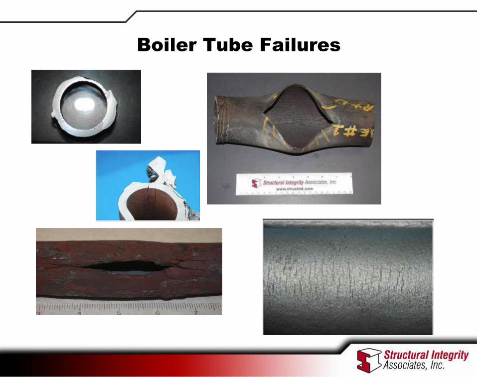
Boiler Tube Failures


Metallurgical Analysis
• A determination of the mode of damage responsible for
the failure is an essential component of the root cause
analysis, although in most cases it is not sufficient for
identifying the root cause of failure.
• For critical boiler pressure parts, and tubing in particular,
Metallurgical Analysis is the primary tool for determining
the active damage mechanism, or mechanisms.
• An erroneous or incomplete analysis is worse than no
analysis at all, since it will prompt inappropriate responses
that do not address the basic cause of failure - and BTFs
will continue

Elements of a Successful Metallurgical
Analysis
• A sample containing the failure of interest or containing evidence of the
damage responsible for the failure
• Accurate background information
• A laboratory equipped to conduct all non-destructive and destructive
tests required to fully characterize the metallurgical condition of the
Sample
• Materials specialists who can formulate a test program to accurately
reveal the metallurgical condition of the sample, who can execute that
program, and who then can correctly interpret the information obtained
from the tests – Expertise in ferrous metallurgy, with broad experience in non-ferrous
– A basic understanding of the design and operation of boilers and pressure
parts
– A basic understanding of manufacturing/construction processes as they apply
to boiler tubing

Tube Sampling
• Photo documentation of failed area
• Drawing/sketch showing failure location in the boiler
• Labeling of the tube(s) in-situ (flow direction, hot side)
• Removal of the tube(s) via mechanical means
• Data snap shot of operations, water chemistry,
excursions.


Failure Mechanisms
Water Touched Tubes
SELECTIVE WELD ATTACK • Corrosion Fatigue
• Flyash Erosion
• Hydrogen Damage
• Acid Phosphate Corrosion
• Caustic Gouging
• Waterwall Fireside Corrosion
• Thermal Fatigue (Waterwalls, Economizer Inlet
Headers)
• Thermal-Mechanical and Vibrational Fatigue
• Flow-Accelerated Corrosion
• Sootblower Erosion
• Short-term Overheating
• Low Temperature Creep
• Pitting
• Coal Particle Erosion
• Acid Dewpoint Corrosion

• Longterm Overheating/Creep
• SH/RH Fireside Corrosion
• Dissimilar Metal Weld Failures
• Short-term Overheating
• Stress Corrosion Cracking
• Explosive Cleaning Damage
• Thermal-Mechanical and Vibrational Fatigue
• Rubbing/Fretting
• Pitting
• Graphitization
• Chemical Cleaning Damage
• Maintenance Damage
• Material Flaws
• Welding/Repair Defects
Failure Mechanisms
Steam-Touched Tubes

Cycle Chemistry
Cycle Chemistry (CC) is one of the most important factors
of availability and performance or boilers and HRSG’s
• influences about 50% of the boiler tube failures (BTF)
• influences about 70% of the HRSG tube failures (HTF)
• influences/controls every one of the main damage
mechanisms in the steam turbine except liquid droplet
erosion
• has a major influence on condenser tube and feedwater
heater tube failures.
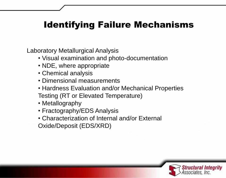
Identifying Failure Mechanisms
Laboratory Metallurgical Analysis
• Visual examination and photo-documentation
• NDE, where appropriate
• Chemical analysis
• Dimensional measurements
• Hardness Evaluation and/or Mechanical Properties
Testing (RT or Elevated Temperature)
• Metallography
• Fractography/EDS Analysis
• Characterization of Internal and/or External
Oxide/Deposit (EDS/XRD)

• Visual examination and photo-documentation - A preliminary diagnosis of the
mechanism can often be made based on visual examination of the macroscopic
damage features; this will determine the number and location of specimens
removed for destructive analysis.
• Photo-documentation will record distinctive features of the damage prior to sample
cutting and can indicate location of specimens removed for destructive analysis.
• Dimensional Measurements can:
Identify location and magnitude of wall loss
Identify degree of service-induced swelling, which is a measure of accumulated
creep damage
Identifying Failure Mechanisms

Identifying Failure Mechanisms
Metallography • Microstructure
• Microstructural degradation (spheroidization,
graphitization) or transformation
• Damage type, extent, and morphology
(cracking/fracture path, rupture features, corrosion,
pitting, cavitation)
• Appearance and thickness of internal and external
oxides/scales/deposits

Visual examination and photo-documentation – A preliminary diagnosis of the mechanism can often be made based on visual
examination of the macroscopic damage features; this will determine the number
and location of specimens removed for destructive analysis.
– Photo-documentation will record distinctive features of the damage prior to
sample cutting and can indicate location of specimens removed for destructive
analysis

Carbon Steel Graphitization
Alloy Steel Creep

Metallography-Damage Extent and Morphology
Manufacturing Lap

Fatigue striations indicating high cycle
fatigue. Arrow indicates area of
fatigue striations and the direction of
propagation.
“Thumb-nail” shaped fatigue
crack initiating at attachment
weld on OD surface of tube.

Characterization of Internal and/or External Oxides/Deposits

Compositional Analysis – Does the material meet specifications? • Are elements critical to service at low end/high end of permissible
range (e.g., Cr, Mo, Cb, N, Al)
– Equally important, are non-specified elements present at levels
that would affect material performance adversely • Low strength stainless steel (low nitrogen)
• Low temperature creep crack growth (high nitrogen and surface-active
tramps, such as arsenic, tin, antimony)
• Poor rupture ductility in welds and BM (high surface-active tramps)


Take-Aways
• You don’t have to live with Boiler or HRSG Tube
Failures
• Attack problem from a systematic, continuous
improvement approach
• Don’t assume what caused the failure, may failures
look the same but have a completely different
mechanism. Metallography and deposit analysis are
necessary to determine the correct mechanism
• Water Chemistry!
• All met labs are not created equal

Joe Maciejczyk, PE
Structural Integrity Associates
Cell: 804-502-2820
www.structint.com


