3-PASS FIREBOX DESIGN with Wet Back Firetube Construction LOW PRESSURE BOILER Capacities from 7.4 to 650 BHP. 248 to 21759 MBTU/HR. SERIES 100 BOILER & WELDING CO., INC. SKID MOUNTED MODULAR PACKAGED STEAM Pressure 15 max PSI. HOT WATER Section IV 30-60, 100 PSI. “The 100 Series has a large furnace volume for Ultimate Combustion Efficiency.”
Transcript
3-PASS FIREBOX DESIGNwith Wet Back Firetube Construction
LOW PRESSURE BOILERCapacities from 7.4 to 650 BHP.
248 to 21759 MBTU/HR.
SERIES 100
BOILER & WELDING CO., INC.
SKID MOUNTEDMODULAR PACKAGED
STEAMPressure 15 max PSI.
HOT WATER
Section IV30-60, 100 PSI.
“The 100 Series has a large furnace volume for Ultimate Combustion Efficiency.”
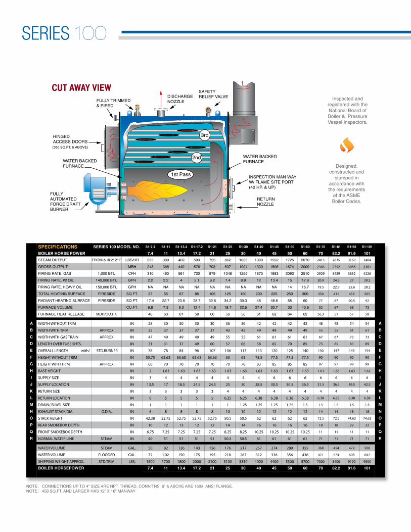
CUT AWAY VIEW
(350 SQ.FT. & ABOVE)
SPECIFICATIONS SERIES 100 MODEL NO. S1-7.4 S1-11 S1-13.4 S1-17.2 S1-21 S1-25 S1-30 S1-40 S1-45 S1-50 S1-60 S1-70 S1-81 S1-92 S1-101
NOTE: CONNECTIONS UP TO 4” SIZE ARE NPT. THREAD, CONN’TNS. 6” & ABOVE ARE 150# ANSI FLANGE.NOTE: 458 SQ.FT. AND LARGER HAS 12” X 16” MANWAY
SERIES 100
Designed, constructed and
stamped inaccordance with the requirements
of the ASME Boiler Codes.
Inspected and registered with the National Board of Boiler & Pressure Vessel Inspectors.
BOILER DESIGN: Three-Pass “FireBox” design with stress relieving “Wet Back” Firetube construction. Pressure designs for steam aren 7.4-650 HP } 15 psi. max.Built to Section-IV ASME Code.Hot Water pressures models are fromn 7.4-332 HP } 100 psi. max.n 400- 650 HP } 60 psi. max. Built to Section-IV ASME Code. Hot water temperature not to exceed 250°F at or near the outlet of boiler.
STEAM MODEL TRIM: Safety relief valve, operating pressure control, high limit pressure control with manual reset, steam pressure gauge with syphon, combination pump control and low water cut-off with gauge glass assembly and drain valve, auxiliary low water cut-off with manual reset.
HOT WATER MODEL TRIM: Safety relief valve, operating temperature control, high limit temperature control with manual reset, combination pres-sure & temperature gauge, low watercut-off control with manual reset.
BURNER: Matched UL listed “forced draft” power burners with factory pre-piped, wired and tested fuel configu-rations for natural gas, propane (LP) gas, No. 2 (diesel) oil, or combination of both gas/oil.
ALL DIMENSIONS ARE IN INCHES CERTIFIED DRAWING AVAILABLE UPON REQUEST.DIMENSIONS SUBJECT TO CHANGE WITHOUT NOTICE.
SERIES 100
HBC-0950808/2014
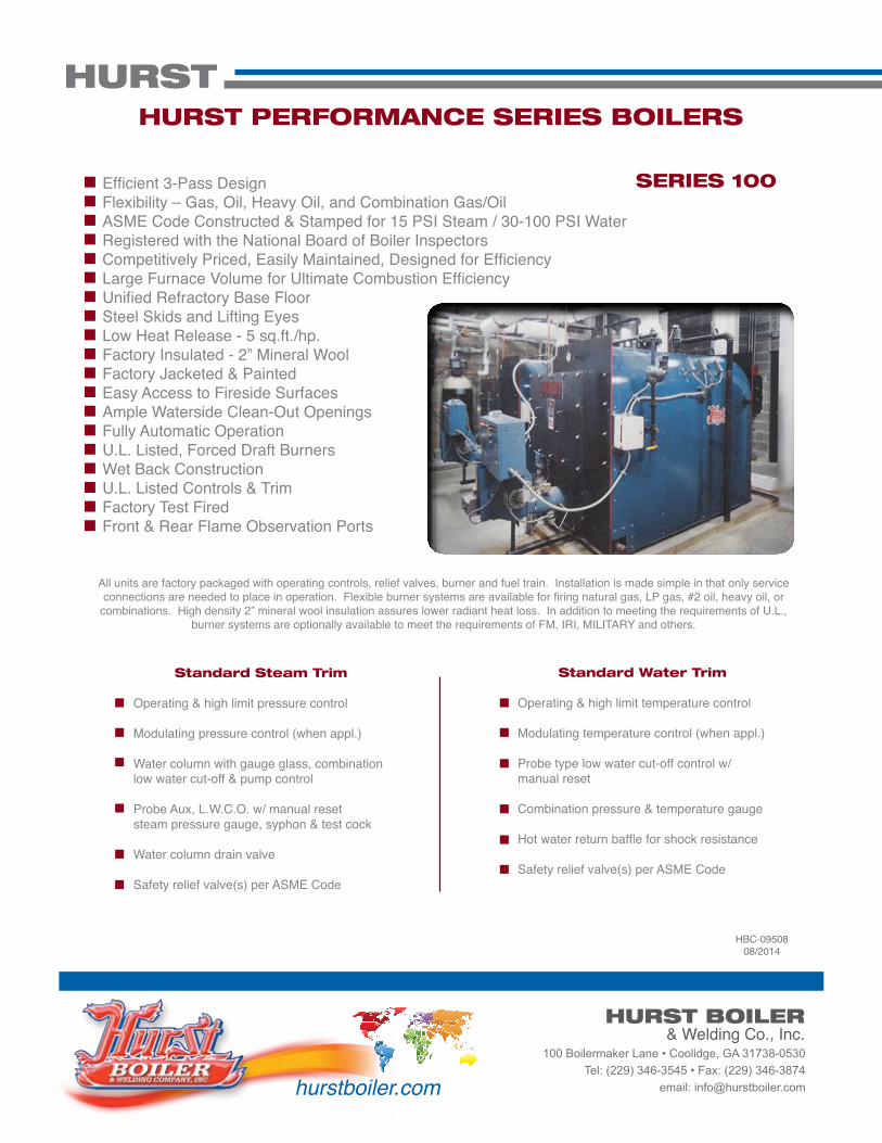
All units are factory packaged with operating controls, relief valves, burner and fuel train. Installation is made simple in that only service connections are needed to place in operation. Flexible burner systems are available for firing natural gas, LP gas, #2 oil, heavy oil, or
combinations. High density 2” mineral wool insulation assures lower radiant heat loss. In addition to meeting the requirements of U.L., burner systems are optionally available to meet the requirements of FM, IRI, MILITARY and others.
Efficient 3-Pass DesignFlexibility – Gas, Oil, Heavy Oil, and Combination Gas/OilASME Code Constructed & Stamped for 15 PSI Steam / 30-100 PSI WaterRegistered with the National Board of Boiler InspectorsCompetitively Priced, Easily Maintained, Designed for Efficiency Large Furnace Volume for Ultimate Combustion EfficiencyUnified Refractory Base FloorSteel Skids and Lifting EyesLow Heat Release - 5 sq.ft./hp.Factory Insulated - 2” Mineral WoolFactory Jacketed & PaintedEasy Access to Fireside SurfacesAmple Waterside Clean-Out OpeningsFully Automatic OperationU.L. Listed, Forced Draft BurnersWet Back ConstructionU.L. Listed Controls & TrimFactory Test FiredFront & Rear Flame Observation Ports
Standard Steam Trim
Operating & high limit pressure control
Modulating pressure control (when appl.) Water column with gauge glass, combinationlow water cut-off & pump control Probe Aux, L.W.C.O. w/ manual resetsteam pressure gauge, syphon & test cock
Water column drain valve
Safety relief valve(s) per ASME Code
Standard Water Trim
Operating & high limit temperature control Modulating temperature control (when appl.)
Probe type low water cut-off control w/ manual reset