Boiling Heat Transfer Dr Vishwas Wadekar Technology Director HTFS Research Aspen Technology Definitions/Terminology Saturation temperature (T sat ) - boiling point temperature at prevailing pressure. For a mixture this will be bubble point temp. Superheat-excess temperature over the saturation value (T - T sat ) •Wall superheat = (T wall -T sat ) Subcooling- opposite of superheat given by (T sat - T ) Quality- Vapour phase mass fraction, ratio of vapour flowrate to total flowrate Subcooled and saturated boiling Pool Boiling
Transcript
Boiling Heat Transfer
Dr Vishwas Wadekar
Technology Director HTFS Research Aspen Technology
Definitions/Terminology�Saturation temperature (Tsat ) - boiling point temperature at prevailing pressure. For a mixture this will be bubble point temp.
� Superheat-excess temperature over the saturation value (T - Tsat)•Wall superheat = (Twall - Tsat)
�Subcooling- opposite of superheat given by (Tsat - T )
�Quality- Vapour phase mass fraction, ratio of vapour flowrate to total flowrate
�Subcooled and saturated boiling
Pool Boiling
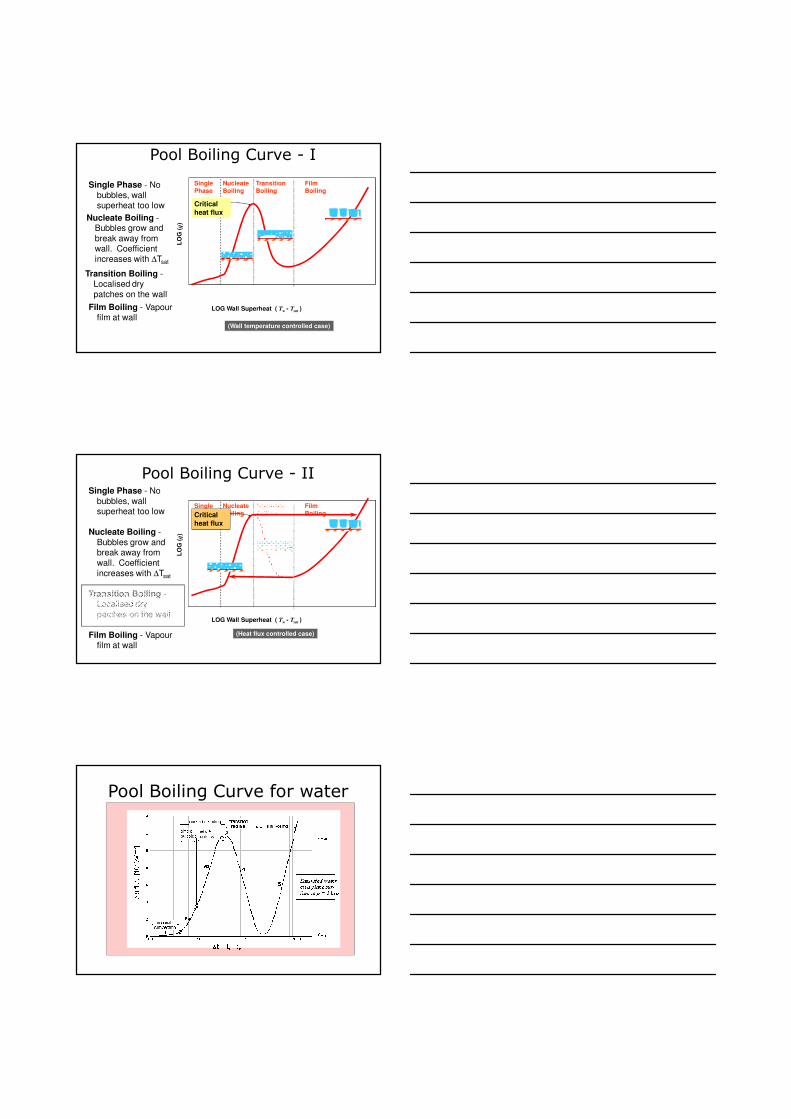
Pool Boiling Curve - I
Single
Phase
Nucleate
Boiling
Transition
Boiling
Film
Boiling
LOG Wall Superheat ( Tw - Tsat )
LO
G (
q)
Critical
heat flux
(Wall temperature controlled case)
Single Phase - No
bubbles, wall superheat too low
Nucleate Boiling -Bubbles grow and
break away from wall. Coefficient
increases with ∆Tsat
Transition Boiling -Localised dry
patches on the wall
Film Boiling - Vapour film at wall
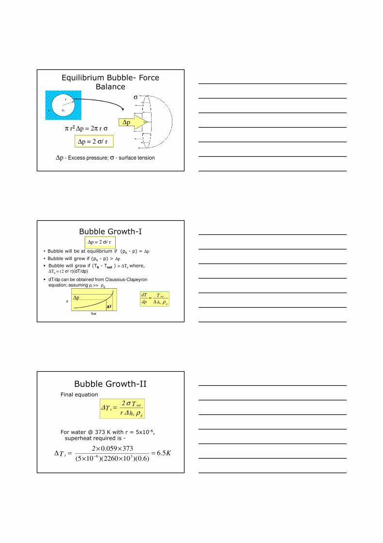
Pool Boiling Curve - II
Single
Phase
Nucleate
Boiling
Transition
Boiling
Film
Boiling
LOG Wall Superheat ( Tw - Tsat )
LO
G (
q)
Critical
heat flux
(Heat flux controlled case)
Single Phase - No
bubbles, wall superheat too low
Nucleate Boiling -
Bubbles grow and break away from
wall. Coefficient
increases with ∆Tsat
Transition Boiling -Localised dry
patches on the wall
Film Boiling - Vapour film at wall
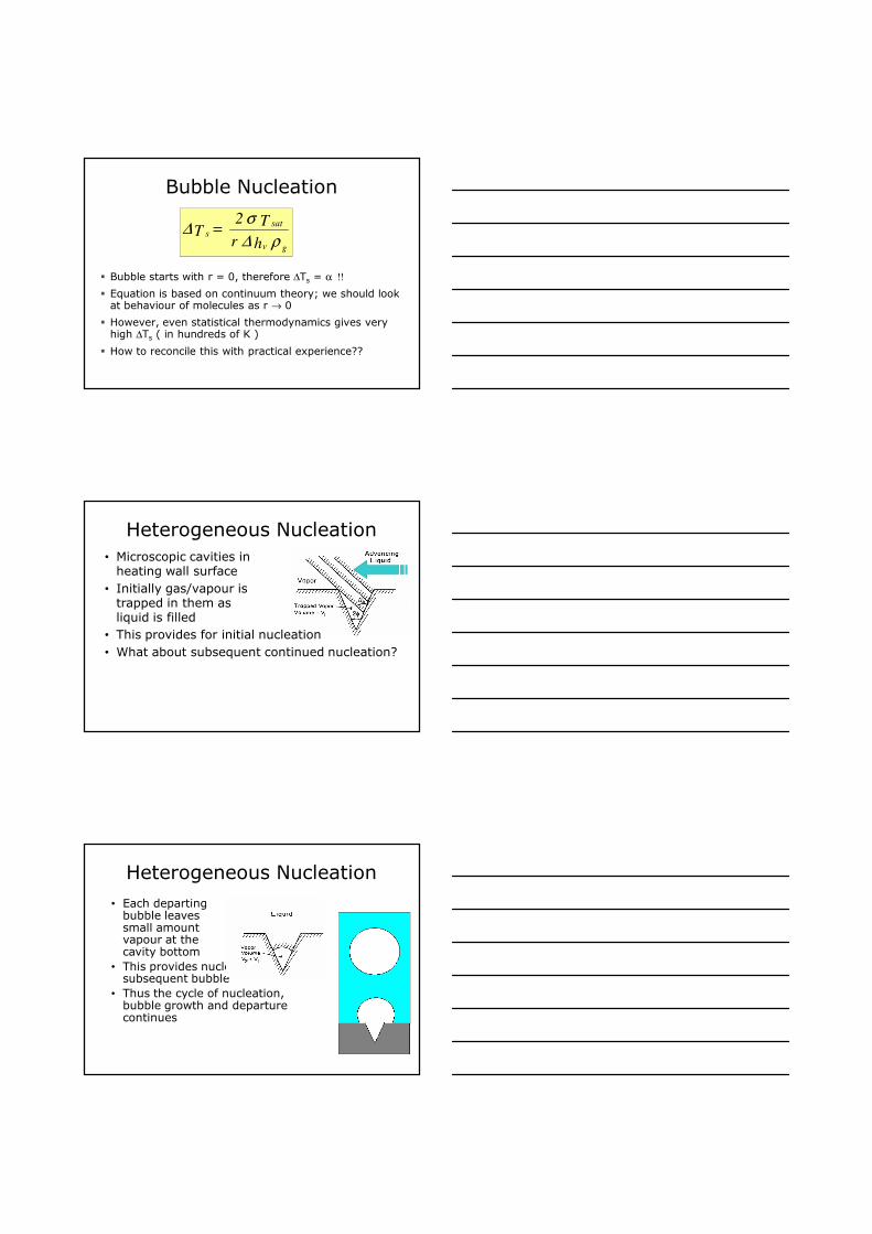
Pool Boiling Curve for water
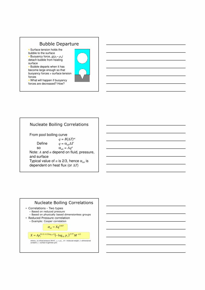
Equilibrium Bubble- Force Balance
r
π r2 ∆p = 2π r σ
∆p = 2 σ/ r
σ
∆p
∆p - Excess pressure; σ - surface tension
p pb
Bubble Growth-I
� Bubble will be at equilibrium if (pb - p) = ∆p
� Bubble will grow if (pb - p) > ∆p
ρ gv
sat
h
T =
dp
dT
∆∆p
∆∆∆∆T
Tsat
p
∆p = 2 σ/ r
� Bubble will grow if (Tb - Tsat ) > ∆Τs where,∆Ts = (2 σ/ r)(dT/dp)
� dT/dp can be obtained from Claussius-Clapeyron
equation; assuming ρl >> ρg
Bubble Growth-IIFinal equation
For water @ 373 K with r = 5x10⁻⁶, superheat required is -
ρ∆
σ∆
gv
sats
h r
T 2 T =
K2
T s 5.6)6.0)(102260)(105(
373059.036
=××
××=∆
−
Bubble Nucleation
� Bubble starts with r = 0, therefore ∆Ts = α !!
� Equation is based on continuum theory; we should look at behaviour of molecules as r → 0
� However, even statistical thermodynamics gives very high ∆Ts ( in hundreds of K )
� How to reconcile this with practical experience??
ρ∆
σ∆
gv
sats
h r
T 2 T =
Heterogeneous Nucleation
• Microscopic cavities in heating wall surface
• Initially gas/vapour is trapped in them as liquid is filled
• This provides for initial nucleation
• What about subsequent continued nucleation?
Heterogeneous Nucleation
• Each departing bubble leaves small amount vapour at the cavity bottom
• This provides nucleation for subsequent bubble
• Thus the cycle of nucleation, bubble growth and departure continues
Bubble Departure� Surface tension holds the bubble to the surface� Buoyancy force, g(ρL– ρV)detach bubble from heating surface � Bubble departs when it has become large enough so that buoyancy forces > surface tension
forces� What will happen if buoyancy forces are decreased? How?
Nucleate Boiling Correlations
From pool boiling curveq = B(∆T)m
Define q = αnb∆T
so αnb = Aqn
Note: A and n depend on fluid, pressure,
and surfaceTypical value of n is 2/3, hence αnb is dependent on heat flux (or ∆T)
Nucleate Boiling Correlations
• Correlations - Two types– Based on reduced pressure
– Based on physically based dimensionless groups
• Reduced Pressure correlation– Example: Cooper correlation
667.0Xqnb =α
where pc is critical pressure (N/m2), pr = p/pc, , M = molecular weight, A =dimensional
constant, ε = surface roughness (µm)
( )( ) 5.055.0
10
log21.012.0log10 −−−
−= MpApX rr
ε
Two-phase Flow Patterns and ∆p Prediction
Definitions/Terminologylg MMM &&& +=
( )lg
g
gMM
Mx
&&
&
+=
( )S
Mm;
S
Mm;
S
MM
S
Mm l
l
g
g
lg&
&
&
&
&&&
& ==+
==
( )
l
g
l
g
g
g
xmU;
xmU
ρρ
−==
1&&
– Mass flow rate
– Vapour quality
– Mass flux
– Superficial velocity
Definitions: Void Fraction
– Void fraction is a volume fraction for gas phase
– For one dimensional model this becomes the area fraction for gas phaseAg
S - total area Ag - gas phase
flow area
S
Ag
g =ε
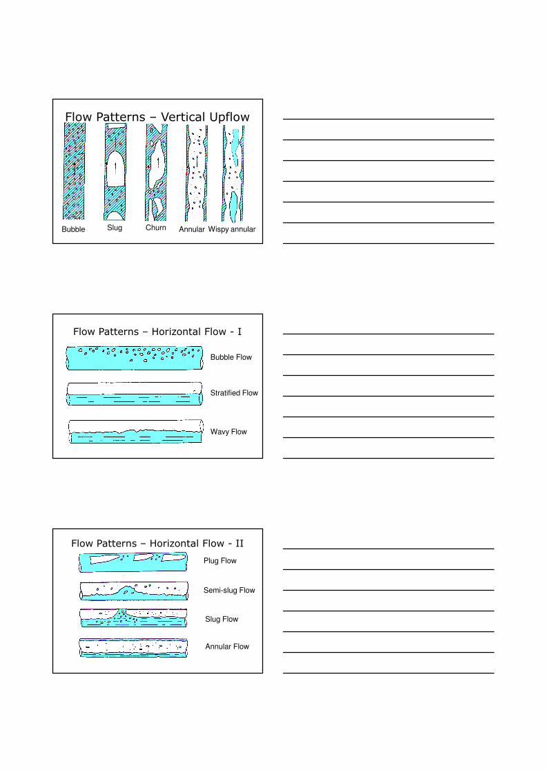
Flow Patterns – Vertical Upflow
Bubble Slug Churn Annular Wispy annular
Flow Patterns – Horizontal Flow - I
Bubble Flow
Stratified Flow
Wavy Flow
Flow Patterns – Horizontal Flow - II
Annular Flow
Slug Flow
Plug Flow
Semi-slug Flow
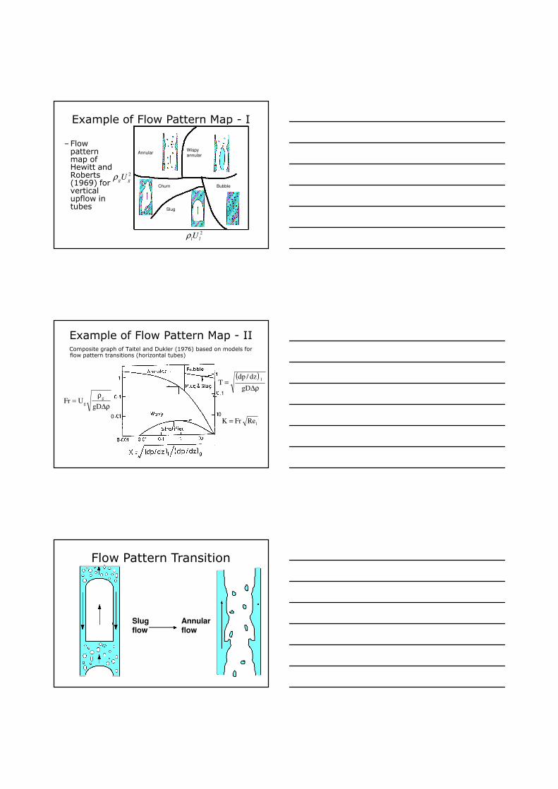
Example of Flow Pattern Map - I
–Flow pattern map of Hewitt and Roberts (1969) for vertical upflow in tubes
2
llUρ
2
ggUρ
AnnularWispy
annular
Churn
Slug
Bubble
Example of Flow Pattern Map - IIComposite graph of Taitel and Dukler (1976) based on models for flow pattern transitions (horizontal tubes)
ρ∆
ρ=
gDUFr
g
g
( )
ρ∆=
gD
dz/dpT
l
lReFrK =00
.1
Flow Pattern Transition
Slug flow
Annular flow
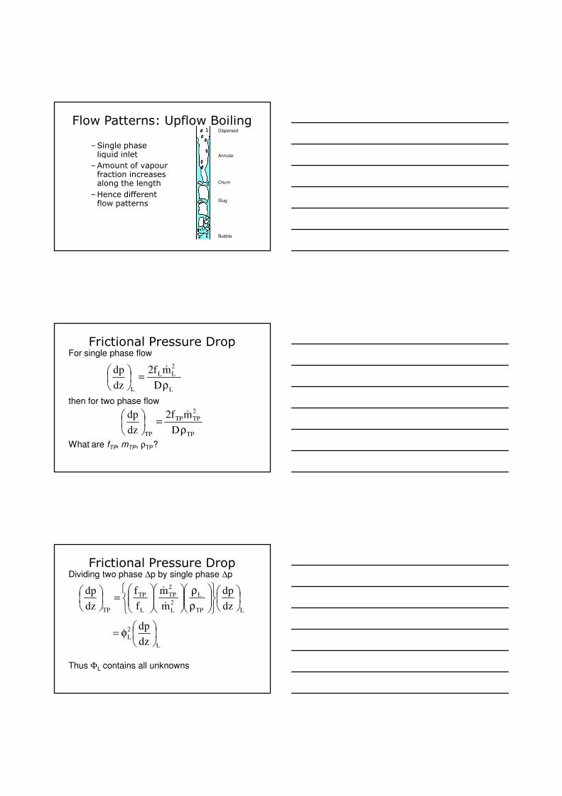
Flow Patterns: Upflow Boiling
Annular
Churn
Slug
Bubble
Dispersed
–Single phase liquid inlet
–Amount of vapour fraction increases along the length
–Hence different flow patterns
Frictional Pressure Drop
L
2
LL
L D
mf2
dz
dp
ρ=
&
TP
2
TPTP
TP D
mf2
dz
dp
ρ=
&
For single phase flow
then for two phase flow
What are fTP, mTP, ρTP?
Frictional Pressure Drop
LTP
L
2
L
2
TP
L
TP
TP dz
dp
m
m
f
f
dz
dp
ρ
ρ
=
&
&
Dividing two phase ∆p by single phase ∆p
Thus ΦL contains all unknowns
L
2
Ldz
dp
φ=
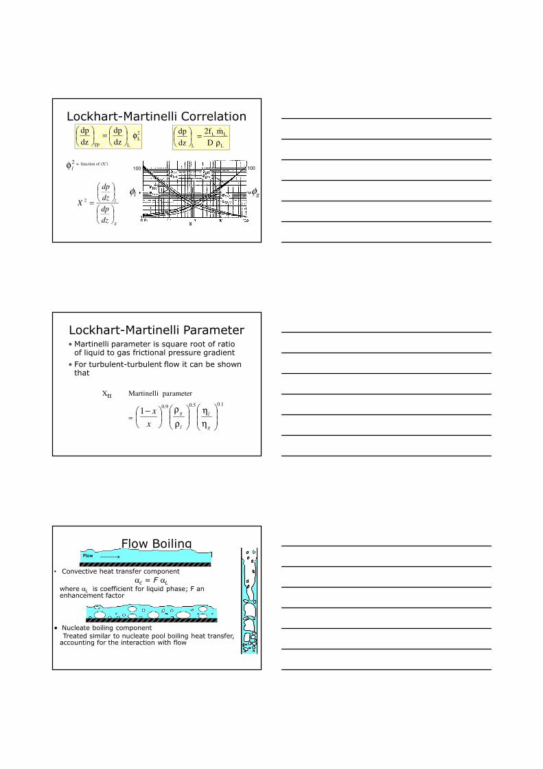
Lockhart-Martinelli Correlation2
L
LTP dz
dp
dz
dpφ
=
L
LL
L D
mf2
dz
dp
ρ=
&
= function of (X2)2
lφ
g
l
dz
dp
dz
dp
X
=2
φl φg
100
X
100
Lockhart-Martinelli Parameter• Martinelli parameter is square root of ratio of liquid to gas frictional pressure gradient
• For turbulent-turbulent flow it can be shown that
Xtt Martinelli parameter
=
1.05.09.01
η
η
ρ
ρ
−
g
l
l
g
x
x
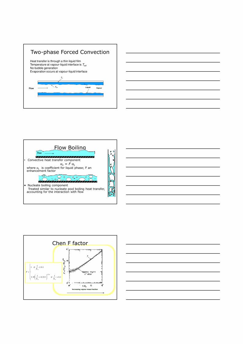
Flow Boiling
• Convective heat transfer component
αc = F αLwhere αL is coefficient for liquid phase; F an enhancement factor
•• Nucleate boiling component
Treated similar to nucleate pool boiling heat transfer, accounting for the interaction with flow
Flow
Components of Flow Boiling
Typical variation of
α for fixed mass
flux
Quality
Heat Tra
nsfe
r C
oeff
icie
nt (W
/m2K
)
Nucleate boiling region
Decreasing q&
Convective Component
Two-phase convective heat transfer componentHere the heat transfer is through faster moving liquid
film being dragged by higher velocity vapour Favourable conditions
- Low pressure and low heat flux- High flow rate and high vapour quality- Plain surface
Flow
Nucleate Boiling Component
Nucleate boiling componentHere the heat transfer is driven by vapour bubble dynamics
Favourable conditions- High pressure and high heat flux


![A study on film boiling using a Coupled Level Setgrowth in Film Boiling. Son and Dhir [10] simulated film boiling on a horizontal surface, solving governing equations for both liquid](https://static.documents.pub/doc/80x56/5e6f3ea98fb2d905a90386f5/a-study-on-film-boiling-using-a-coupled-level-growth-in-film-boiling-son-and-dhir.jpg)


![A study on film boiling using a Coupled Level Set · growth in Film Boiling. Son and Dhir [10] simulated film boiling on a horizontal surface, solving governing equations for both](https://static.documents.pub/doc/80x56/5e6f3a4dac3fa621a44d3e37/a-study-on-film-boiling-using-a-coupled-level-set-growth-in-film-boiling-son-and.jpg)