39
1 Bolted connectors Nexans Power Accessories

1
Bolted connectors
Nexans Power Accessories
2
Summary
1. The function of bolted connectorsThe functionPhysical parametersCrimped versus bolted connectorsAdvantages of bolted connectors
2. Presentation of GHP connectorsHistory of the screwsScrew designsMulti shear level: screw of GPHInstallation with cordless impact wrenchLow voltage bolted connectorsMedium voltage bolted connectorsTests according to EN 61238High voltage screwed connectorsBimetallic contactsSplit bolted contacts
3. ApplicationsRequirements of EDFExamples
4. Conclusion

3
1. The function of bolted connectors

4
The function of bolted connectors
Connecting of power cables or with other energy devices Low voltage, medium voltage and high voltage With conductor cross sections 6 – 300 – 630 – 1000 – 2000 – 2500 mm²
The connection must transmit electrical energy - means high current - duringthe whole lifetime without negative influence on:
the own function joints, terminations and plugs concerning their
thermal, mechanical and insulation behaviour

5
Electrical Contact – Quality Factor
pretented contact areaAsmechanical suporting area At
electrical conductive areaAw
non conductivelayer
homogeneousconductor connectio
n
Rconnector
Rconductor
RconnectorRconductor
quality factor k =
Aw << As
micro contacts
6
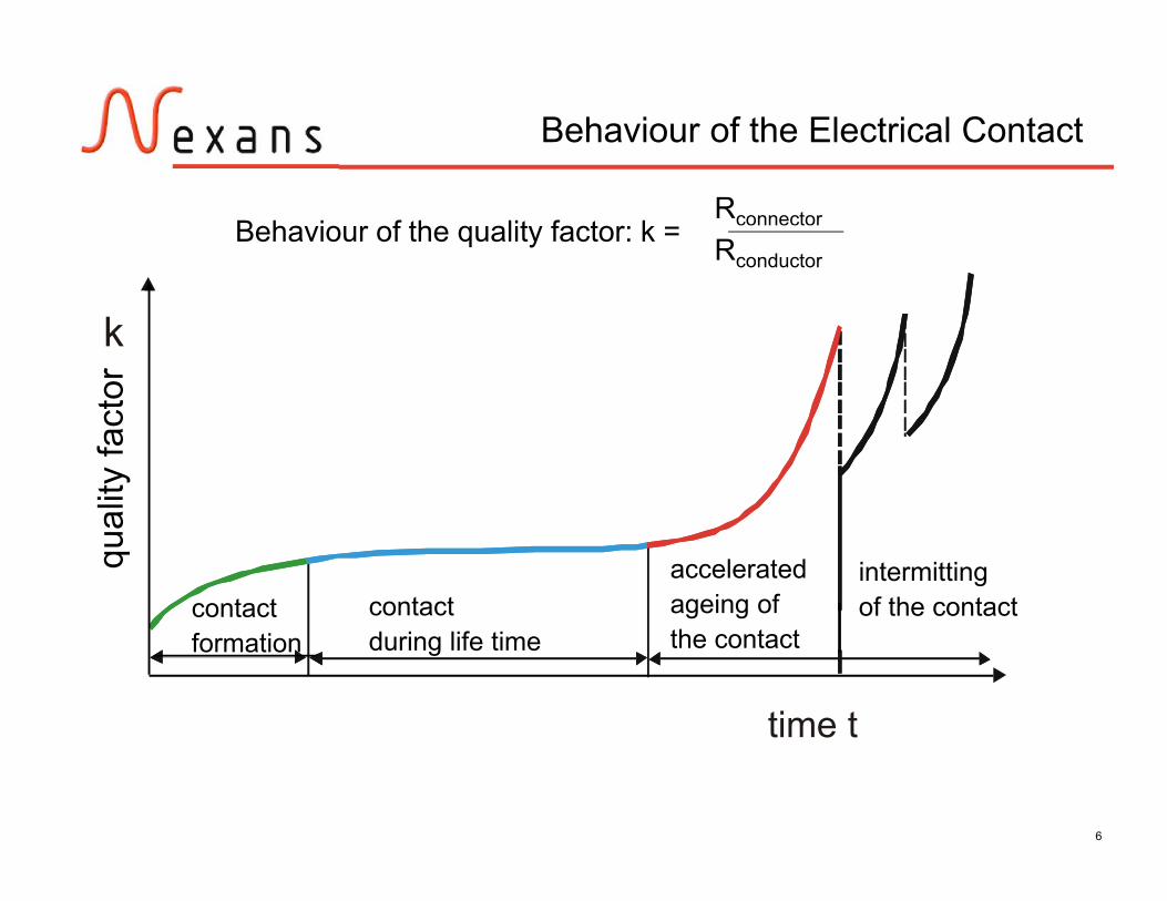
Behaviour of the Electrical Contact
time t
k
Rconnector
RconductorBehaviour of the quality factor: k =
qual
ity fa
ctor
contactformation
contactduring life time
acceleratedageing ofthe contact
intermittingof the contact

7
Rscrews
Iscrews
Rbody
Ibody
current Iconductorconductor
current I
connector resistance Rconn
The connector resistance Rconn depends on: the resistance of the connector body and of the screws (material, shape) the contact resistance between conductor and connector body the contact resistance between conductor and screw tip the contact resistance between the wires of the conductor
The high rated currents Iof the cable have to becarried by the connectorduring the whole life time.
The temperature*) of the connection must be low to decrease the ageing of the contacts.That means that the losses P = I² * Rconn must be low.For that reason the connector resistance Rconn must be low.
*) the temperature can be influenced by heat transfer due to conduction, radiation, convection (continuous current) and heat storage(short circuit current)
Connector Resistance and Losses

8
contactshapecontact force
contact resistance
cont
act r
esis
tanc
e [
]
contact force Fc [N]
*)
*) from: Böhme, H. : Mittelspannungstechnik.Verlag Technik GmbH; Berlin, München,1992
material matching
A low contact resistance Rconn between: conductor and connector body conductor and screw tip the wires of the conductor can be achievedby a high contact force F grooves to break non conductive
layers and to generate a defined contact area
Effects on the Contact Resistance
grooves
F
Mscrew
conductor
force F
Connector groove
force F
current
conductor
oxide layer
current path

9
Contact Resistance dependingon the Screwing Moment
screwing moment Mscrew
contact force Fc
connector resistanceRconn
MscrewFscrew=
k1 P + k2 µG d2 + k3 µS D
diameterthreadpitch
friction
k1: 0,16k2: 0,58k3: 0,5
tipdiameterfriction thread
Fscrew
Fc
tip
thread
Mscrew
conn
ecto
r res
ista
nce
Rco
nn[µ
]
screwing moment Mscrew [Nm]
Measured resistanceof differentconnectors

10
Contact Ageing
The electrical resistance of a connection can be increased by:
chemical ageing, means increasing of oxide layers anddue to that constriction of micro contacts
floating - espacially of aluminium conductors - and due tothat reducing of the contact force
Both effects will be accelerated at higher temperatures
Because of that the electrical losses should be as small aspossible

11
Bolted connections – screwing
• Are range taking concerning conductorcross section for low and mediumvoltage application.• Are adapted to the cross section rangeof the accessories.• Copper and aluminium conductors, whichcould be round or sectoral shaped,stranded or solid,can be connected
• No special toolsfor the installation.
Compression connections – crimping
• For every cross section a special crimpconnector is needed.• A copper conductor needs a copperconnector.• An aluminium conductor needs analuminium connector.
• Heavy tools and alot of different diesare necessary
Crimped versus Bolted Connectors

12
Range taking concerning conductor cross section for low and mediumvoltage application
Adapted to the cross section range of the accessories
Copper and aluminium conductor
Round, sectoral shaped
Stranded, solid
No special tools for the installation.
Advantages of Bolted Connectors

13
2. Presentation of the GHP connectors

14
History of Screw Development
Development of bolted contacts since the eighties worldwide.
1. Headless screws (grub screw) with inner hexagon installation with a torque wrench which shows the required moment or depending on the „intuition“ of the installer
2. Shear screws with one shear level predetermination of the right shear moment by the manufacturer usable for low voltage connectors / high voltage connectors
3. Multilevel shear screws for medium voltage application predetermination of the right shear moment regarding the cross section NPAG screw: biggest conductor with the biggest moment (contact force) screw shears off nearly flash with the surface of the connector no negative influence on the electrical field of the accessories

15
Design of Bolted Contacts/Screwsdepending on the Voltage Level
Low Voltage- big excentricity and rel. big excess length after shear-off allowed- screws with 1 - 2 shear levels
Medium Voltage-only small excentricity and small excess length after shear-off- screws with 2 - 4 shear levels
High Voltage- round conductor channel especially adapted to the conductor- no excentricity- one shear level- high force screws for aluminium Milliken conductor with big cross section

16
Multi Shear Level Screw from NPAG
The NPAG multi shear level screwis the only one on the market whichhas both main advantages.
Biggest momentfor the biggest cross section:means biggest contact forcefor the biggest conductorwith the biggest nominal current
Installation with standard keys whichare commercially available
During shear off the contact partof the screw will not be influenced(no constriction of the contact part).
Force
Force
Installation with:allen key
hexagon socket

17
Low Voltage Screwing Connectors

18
Low Voltage Screwing Connectors
Screws with one (max. two) shear levels
• sectoral shaped orround conductor channel
• rel. big excentricity• grooves cross and lengthwise piercing of solid conductors

19
Typical Low Voltage Screwing Connectors
416 MS-SV 6-16 4-16 6-16SE1650 25-50 10-50 35-50 35-50 10-50SE25150 35-150 25-50 35-120 25-95 25-9535150 SV 35-150 35-50 35-120 35-95 35-9525150 SV 25-150 25-50 35-120 25-95 25-95SE25150SM 35-150 25-50 35-150 25-150 25-150SE150300 150-300 / 150-300 150-300 150-300

20
Medium Voltage Screwing Connectors

21
Medium Voltage Screwing Connectors
Screws with 2 - 4 shear levels, made of brass with tinned surfaceor made of aluminium alloy Connector body made of aluminium alloy Sectoral shaped or round conductor channel with small excentricity,with or without separating web, tinned surface Centering rings (plastic) Additional tinned tubes for very small cross section .

22
Al in mm2 Cu in mm2
rm(v) re rm(v)M16-95 16-95 16-95 10-95M50-150 50-150 50-150 50-120M70-240*) 70-240 70-240 70-240M95-240 95-240 95-240 95-240MRL(T)95-240 95-240 95-240 95-185M120-300 120-300 120-300 120-300M185-400 185-400 185-400 185-400M400-630 400-630 400-630 400-630
*) sectoral shaped conductor possible
Typical Medium Voltage Screwing Connectors

23
Test according to EN 61238-1
Electrical test procedure
6 connectors have to be tested: 200 load cycles
(median connector 100°C;reference conductor: 120 – 140 °C)
6 short circuits(reference conductor: 250 – 270 °C) 800 load cycles measuring of the resistance and of
the temperature.
Mechanical test procedure
3 connectors have to be tested:- tensile force F during 1 min no damaging or sliding

24
High Voltage Screwing Connector
Screws with one shear level (up to 100 .. 120 Nm) High force screws for Aluminium Milliken conductor Round conductor channel especially adapted to the conductor No excentricity Connecting parts up to 2000 (2500) mm² according to customerrequirements

25
Connectors – Electrical Contacts
Electrical and mechanical requirements
Transmission of electrical energy during the whole lifetimewithout negative influence on the own function joints, terminations and plugs concerning their
thermal, mechanical and insulation behaviour
Ensure the required tensile strength

26
Lean Bolted Connector M70 – 240 for round andsectoral shaped Al and Cu conductor
Integrated separation webagainst moisture and oil;absolutely leakproofbecause of machining
Optimized fine thread fora big force and a high stability
Well defined grooves:very good electrical contact and mechanicalbehaviour

27
Copper Aluminium Parts
Connecting of copper and aluminiumby a very high force ideal electrical contact
between both materials
Manufacturing of cable lugs or otherby forging and / or machiningfor an especially high current carrying capability
28
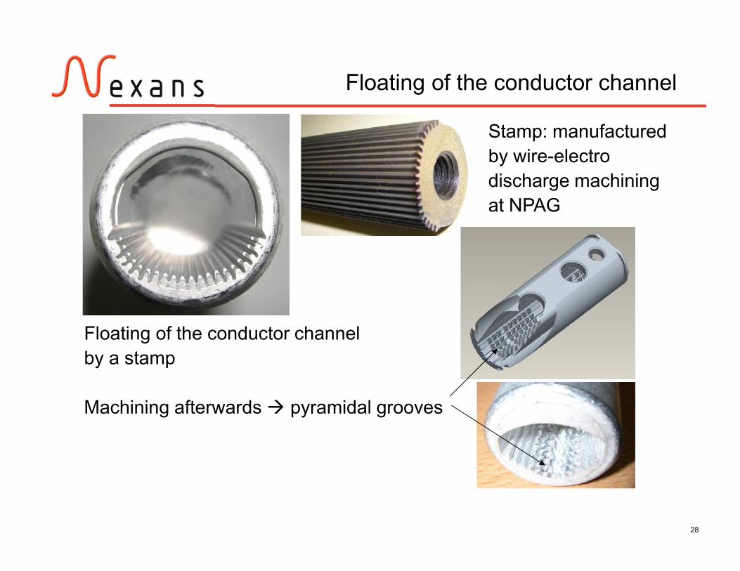
Floating of the conductor channel
Floating of the conductor channelby a stamp
Machining afterwards pyramidal grooves
Stamp: manufacturedby wire-electrodischarge machiningat NPAG

29
Split Bolt Connectors
split screw with one shear level
Split Bolt BranchConnector according tocustomer requirements
split with grooves to reduce the electrical resistance
Available:70 – 240 mm²120 – 300 mm²185 – 400 mm²
split with grooves to reduce the electrical resistanceSpecial shape for adjustmentduring connection of both parts

30
3. Applications

31
Demand of EDF France
EDF wants the introduction of bolted contacts for the whole rangeof the medium accessories: joints, terminations and connectors by2010.
All the accessoires need to pass the electrical qualification tests onthe contacts (IEC 61238) and the products (Cenelec HD629.1 S1).
The product redesign program is now half way. The joints, outdoorterminations and 400A connectors are already qualified.

32
EDF will change from deep indent to bolted contacts until 2010.>>> NPAG developed connectors and lugs for that reason.
M70-240 connector 400A T-plug lug Indoor/outdoor lugs Branch connector
For cross sections 70mm² - 240mm² round and sectoral shaped aluminium and copperconductors (50 mm² is possible by using tinned aluminium tubes)
250 A elbow and straight lug (with screwed copper PIN)for cross sections 35 – 95 mm² round stranded copper and aluminium conductor
Bolted Contacts for EDF

33
Test of Bolted Contacts for EDF according toEN 61238-1
Electrical test procedure
6 connectors have to be tested.
- 200 load cycles: median connector 100°C; reference conductor: 120 – 140 °C- 6 short circuits: reference conductor: 250 – 270 °C- 800 load cycles- measuring of the resistance and of the temperature
Mechanical test procedure
3 connectors have to be tested.
- tensile force F during 1 min no damaging or sliding

34
Test of Bolted Contacts for EDF according toEN 61238-1
400A T-plug lug
Heating cycle with 800 A
reference conductor
6 barrels
Test arrangement
240 mm² aluminiumround stranded

35
barrelpalm
Test of Bolted Contacts for EDF according toEN 61238-1
400 A T-plug lug
Palm
Barrel with 240 mm² aluminiumround stranded
Barrel
400A T-plug lug

36
Test of Bolted Contacts for EDF according toEN 61238-1
Connector M 70-240
Electrical test with 240 mm² copper
Tensile test with 240 mm² copper

37
Export of NPAG Products into around50 Countries
NPAGHof (Germany)

38
4. Conclusion

39
Conclusion
Bolted contacts are getting more and more the standard in‘advanced countries’ in electrotechnical applications.
Nexans has with GPH the state of the art in the development ofthis product line.
Special and customised designs are possible based on an indepth product knowledge.


