Page 1
S1
Supporting Information
Bonding state synergy of NiF2/Ni2P hybrid with co-existence of covalent and ionic bond as a robust catalyst for energy-relevant water and urea electrooxidation
Hui Liu, Zong Liu and Ligang Feng*
School of Chemistry and Chemical Engineering, Yangzhou University, Yangzhou 225002, PR
China.
Email: [email protected] ; [email protected] (L Feng*);
Electronic Supplementary Material (ESI) for Nanoscale.This journal is © The Royal Society of Chemistry 2019
Page 2
S2
1. Experimental section
1.1 Materials
All chemicals used were of analytical grade and used as received. Nickel nitrate hexahydrate
(Ni(NO3)2·6H2O), Urea (NH2CONH2), ammonium fluoride (NH4F) and Sodium
hypophosphite monohydrate (NaH2PO2) are from Aladdin Chemistry Co Ltd. Nafion (5
wt%) is from Sigma-Aldrich Co. Ultrapure water (resistivity ≥ 18.2 MΩ cm-1) was used to
prepare the solutions.
1.2 Preparation of precursor and NiF2, Ni2P, NiF2/Ni2P
The precursor was synthesized by hydrothermal method. Ni(NO3)26H2O, urea (molar ratio
1:5) and an appropriate amount of ammonium fluoride were added into 30 mL ultrapure
water under magnetic stirring to form a homogeneous solution. Then, the obtained solution
was transferred into a 50 mL Teflon-lined stainless steel autoclave and heated at 120 oC for
6 h. After cooling down to room temperature, the product was collected by centrifugation
and washed with deionized water several times. Finally, it was dried at 60 oC in a vacuum
oven for further use.
The as-prepared precursor and ammonium fluoride were loaded into a ceramic boat with a
molar ratio of 1:20. The ammonium fluoride was placed at the upstream of the ceramic boat.
Then, it was calcined at 350 oC for 2 h under N2 protection. After cooling to room
temperature, NiF2 was achieved by centrifugation and drying in a vacuum oven overnight.
The chemical reaction can be express as follows for the NiF2 synthesis[1].
(1)𝑁𝑖2 + + 4𝑁𝐻4𝐹 100℃
→ (𝑁𝐻4)2𝑁𝑖𝐹4 + 2𝑁𝐻4+
(2) (𝑁𝐻4)2𝑁𝑖𝐹4 ∆
→ 𝑁𝐻4𝑁𝑖𝐹3 + 𝑁𝐻3↑ + 𝐻𝐹
(3) 𝑁𝐻4𝑁𝑖𝐹3 350℃
→ 𝑁𝑖𝐹2 + 𝑁𝐻3↑ + 𝐻𝐹
The as-prepared precursor and sodium hypophosphite monohydrate were loaded into a
ceramic boat with a molar ratio of 1:5 and the sodium hypophosphite monohydrate was
placed at the upstream of the ceramic boat. Then, it was calcined at 300 °C for 2 h under N2
protection. After cooling to room temperature, Ni2P was obtained by centrifugation and
Page 3
S3
drying in a vacuum oven overnight. The relevant chemical reaction can be denoted as below
for the Ni2P fabrication[2].
(1) 2𝑁𝑎𝐻2𝑃𝑂2 200℃
→ 2𝑁𝑎 + + 𝐻𝑃𝑂42 ‒ + 𝑃𝐻3↑
(2)16𝑁𝑖2 + + 9𝑃𝐻3 + 4𝐻2𝑂 300 ℃
→ 8𝑁𝑖2𝑃 + 𝐻𝑃𝑂42 ‒ + 34 𝐻 +
Typically, NiF2 and sodium hypophosphite monohydrate were put into a quartz boat with a
molar ratio of 1:5 and calcined at 300 °C for 2 h under N2 protection in a tube furnace. After
cooling to room temperature, NiF2/Ni2P was obtained by centrifugation and drying in the
vacuum oven for use.
1.3 Physical characterization
Powder X-ray diffraction (XRD) patterns were tested on a Bruker D8 Advance powder X-
ray diffractometer using a Cu Kα (λ = 1.5405 Å) radiation source operating at 40 kV and 40
mA, and at a scanning rate of 5 ° min−1. The morphology and microstructure of NiF2/Ni2P
were analyzed by scanning electron microscopy (FESEM, Hitachi, S-4800 II, Japan). All
transmission electron microscopy (TEM) and high-resolution TEM (HRTEM)
measurements were conducted on a TECNAI G2 operating at 200 kV. The energy dispersive
X-ray detector spectrum (EDX) images were obtained on a TECNAI G2 transmission
electron microscope equipped with an EDXA detector. All X-Ray photoelectron
spectroscopy (XPS) measurements were carried out on a Kratos XSAM-800 spectrometer
with an Al Kα radiation source. The gas products of NiF2/Ni2P during oxygen evolution
reaction and urea oxidation reaction were probed by gas chromatography (GC, Kechuang,
GC9800) equipped with a thermal conductivity detector (TCD), using a packed TDX01 (1m)
and molecular sieve 5A column (1.5 m). The carrier gas for TCD is Ar (purity≥99.999%),
and the detection limit is ca. 50 ppm. The GC calibration curves were generated by running
various concentration of the H2, O2, N2 using Ar and then response peak area was plotted
against the concentration.
1.4 Electrochemical measurements
The working electrode is prepared as follows. 4 mg as-prepared catalyst and 1 mg carbon
were dispersed entirely into the mixture of 950 μL ethanol and 50 μL Nafion (5 wt %).
Page 4
S4
After sonicated for 30 min to make a homogeneous solution, 10 μL ink was dropped into the
surface of the glass carbon electrode. The electrolyte (1M KOH with and without 0.33 M
urea) were saturated by N2 atmosphere before use. The catalyst of NiF2, Ni2P and NiF2/Ni2P
were comparatively studied. The catalyst ink of NiF2/Ni2P without carbon was also prepared
with the same approach and studied for relevant electrochemical measurements for
comparison.
All the electrochemical measurements were tested in a typical three-electrode system linked
to a Bio-Logic SAS analyzer (France). The NiF2/Ni2P electrode was served as the working
electrode with a graphite rod as the counter electrode; a saturated calomel electrode (SCE)
as the reference electrode was employed through a double salt-bridge and luggin capillary
connected to the working electrode and it was calibrated before and after the experiments.
The working electrode used was a glassy carbon electrode (3.0 mm diameter). All the
potentials used were converted into RHE. (E(RHE) = E(SCE) +0.0591*pH+0.24V)
The catalytic performance of the three samples for OER and UOR were evaluated by cyclic
voltammetry (CV) at a scan rate of 5 mV/s. Electrochemical impedance spectroscopy (EIS)
which was recorded in the above three-electrode cell with the frequency varies from 1000
kHz to 10 mHz. Chronoamperometry of OER was tested in 1.53V vs RHE and UOR was
tested in 1.38V vs RHE. All tests were measured at room temperature (about 25℃).
1.5 Overall water splitting and urea electrolysis
Overall water splitting and urea electrolysis tests were measured in a two-electrode system
with the different catalysts as an anode and commercial Pt/C as a cathode. The CV curves
were tested in the absence and presence of 0.33M urea in 1M KOH at a scan rate of 5 mV/s
with the potential scan range from 1.0 to 1.8 V. The long-term durability of the NiF2/Ni2P
electrode was assessed at constant voltage (1.6V) electrolysis. All data for the two electrode
tests were recorded without iR correction .
1.6 Turnover frequency (TOF) calculation
The TOF values were calculated from the following equation:
Page 5
S5
TOF=(jA)/(4Fn)
j is the current density at overpotential. A is the surface area of the electrode. F is the Faraday
constant (96485 C mol-1), n is the number of moles of active materials that are deposited
onto the electrode. The active sites number actually is not easy to obtain, a simple method
generally employed by assuming all metal cation as an “active site” was also used here and
it was estimated by the number of moles of active materials that are deposited onto the
electrode.[3, 4]
𝑇𝑂𝐹 =𝑗 × 0.07𝑐𝑚2 × 0.001
4 × 96485 ×0.04𝑚𝑔 × 0.001 × 𝑀𝑁𝑖 𝑀𝑡𝑜𝑡𝑎𝑙
𝑀𝑁𝑖
𝑇𝑂𝐹𝑁𝑖𝐹2/𝑁𝑖2𝑃 =𝑗𝜂 = 350 𝑚𝑉 × 0.07𝑐𝑚2 × 0.001
4 × 96485 ×0.04𝑚𝑔 × 0.001 × 59 119
59
= 0.02 𝑆 ‒ 1
𝑇𝑂𝐹𝑁𝑖2𝑃 =𝑗𝜂 = 350 𝑚𝑉 × 0.07𝑐𝑚2 × 0.001
4 × 96485 ×0.04𝑚𝑔 × 0.001 × 59 149
59
= 0.008 𝑆 ‒ 1
𝑇𝑂𝐹𝑁𝑖𝐹2 =𝑗𝜂 = 350 𝑚𝑉 × 0.07𝑐𝑚2 × 0.001
4 × 96485 ×0.04𝑚𝑔 × 0.001 × 59 97
59
= 0.002 𝑆 ‒ 1
𝑁𝑎𝑐𝑡𝑖𝑣𝑒 𝑠𝑖𝑡𝑒𝑠 𝑛𝑢𝑚𝑏𝑒𝑟 = 𝑛 × 𝑁𝐴
𝑁𝑁𝑖𝐹2/𝑁𝑖2𝑃 =0.04𝑚𝑔 × 0.001 × 59 119
59× 𝑁𝐴 = 2.02 × 10¹⁷
𝑁𝑁𝑖𝐹2 =0.04𝑚𝑔 × 0.001 × 59 97
59× 𝑁𝐴 = 2.48 × 10¹⁷
𝑁𝑁𝑖2𝑃 =0.04𝑚𝑔 × 0.001 × 59 149
59× 𝑁𝐴 = 1.62 × 10¹⁷
1.7 Faradaic efficiency calculation for OER
A gas-tight electrochemical cell coupling with a gas sensor to evaluate the gas produced was
used to probe the faradaic yield of NiF2/Ni2P. The working electrode was prepared by drop-
casting catalyst suspension on the glassy carbon electrode with the surface area of 0.07 cm2.
A constant potential (1.53 V vs. RHE) was applied on the electrode and the volume of the
Page 6
S6
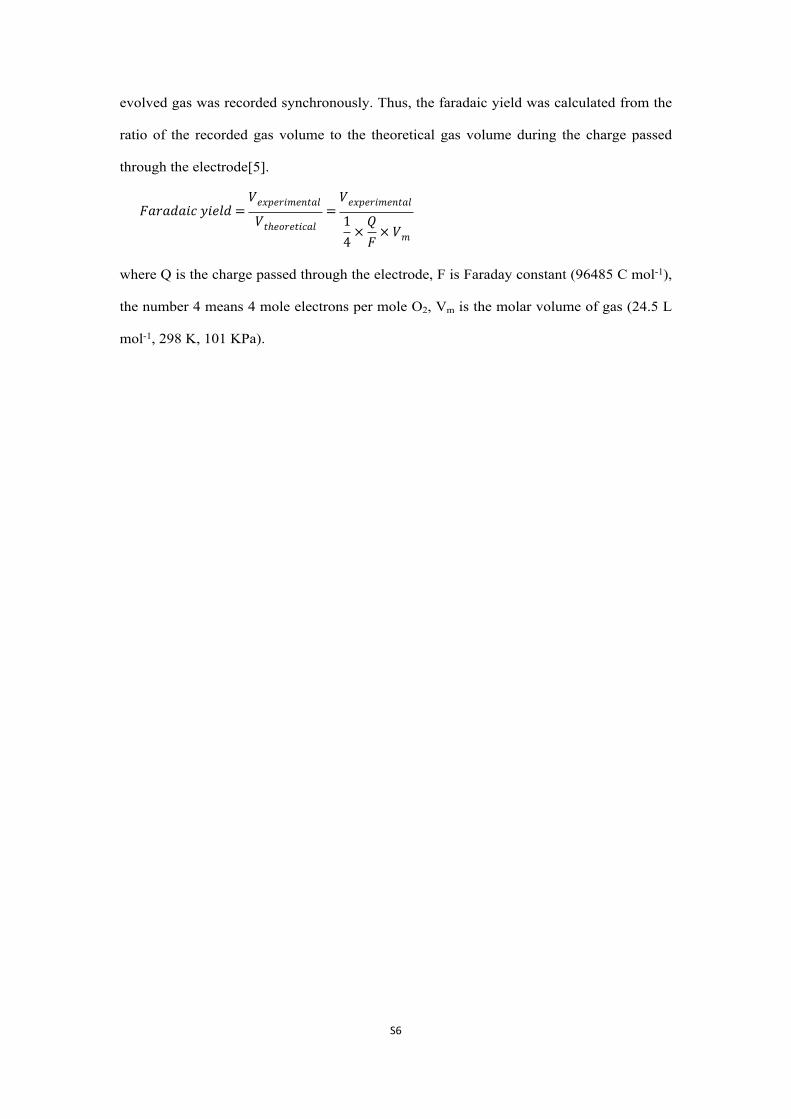
evolved gas was recorded synchronously. Thus, the faradaic yield was calculated from the
ratio of the recorded gas volume to the theoretical gas volume during the charge passed
through the electrode[5].
𝐹𝑎𝑟𝑎𝑑𝑎𝑖𝑐 𝑦𝑖𝑒𝑙𝑑 =𝑉𝑒𝑥𝑝𝑒𝑟𝑖𝑚𝑒𝑛𝑡𝑎𝑙
𝑉𝑡ℎ𝑒𝑜𝑟𝑒𝑡𝑖𝑐𝑎𝑙=
𝑉𝑒𝑥𝑝𝑒𝑟𝑖𝑚𝑒𝑛𝑡𝑎𝑙
14
×𝑄𝐹
× 𝑉𝑚
where Q is the charge passed through the electrode, F is Faraday constant (96485 C mol-1),
the number 4 means 4 mole electrons per mole O2, Vm is the molar volume of gas (24.5 L
mol-1, 298 K, 101 KPa).
Page 7
S7
10 20 30 40 50 60 70 80
Ni(OH)2 0.75H2O PDF#38-0715 Ni(OH)2 0.75H2O
In
tens
ity(a
.u.)
2/degree
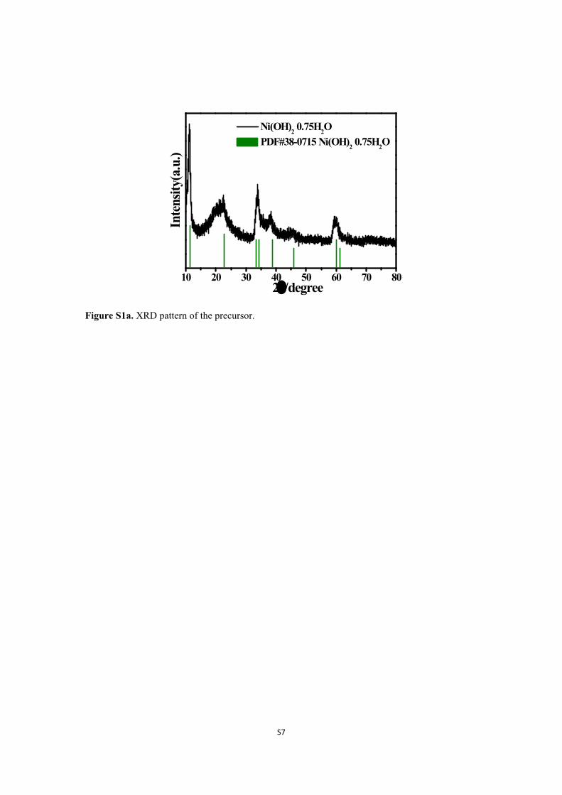
Figure S1a. XRD pattern of the precursor.
Page 8
S8
1200 1000 800 600 400 200 0
P 2pC 1sO 1s
Ni 2p
C 1sO 1s
F 1sNi 2p
P 2pC 1sO 1sF 1s
Ni 2p
Binding energy (eV)
Inte
nsity
(a.u
.)
NiF2/Ni2P Ni2P NiF2
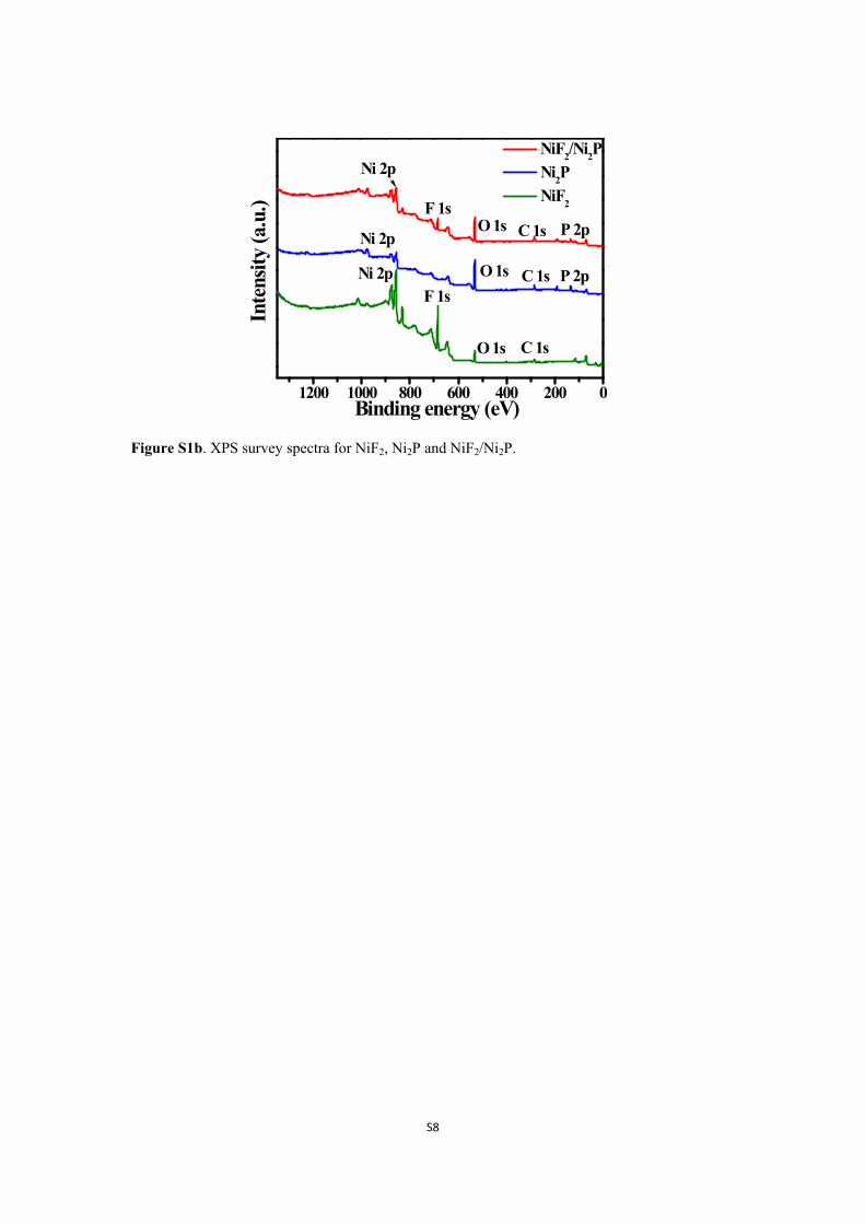
Figure S1b. XPS survey spectra for NiF2, Ni2P and NiF2/Ni2P.
Page 9
S9
280 285 290 295 300
Inte
nsity
(a.u
.)
Binding energy (eV)
NiF2
Ni2P
NiF2/Ni2P
C 1s 284.8eV
Figure S2. XPS spectra of C 1s for NiF2, Ni2P and NiF2/Ni2P.
Page 10
S10
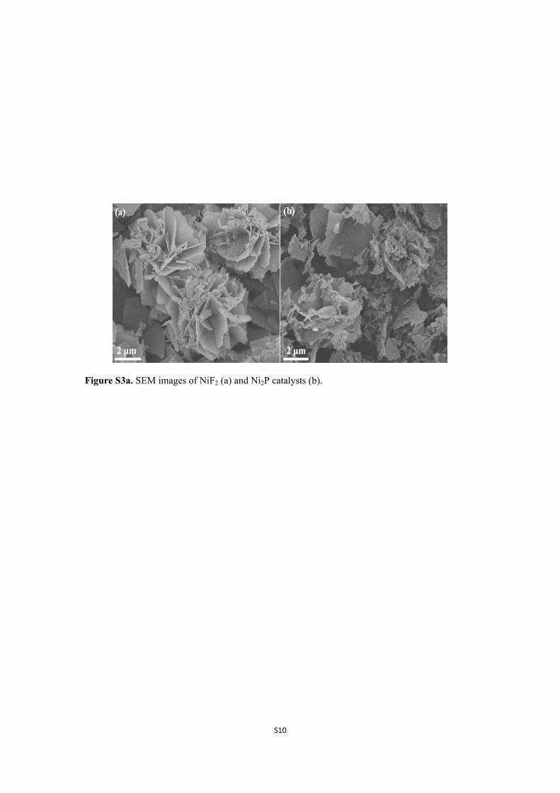
Figure S3a. SEM images of NiF2 (a) and Ni2P catalysts (b).
Page 11
S11
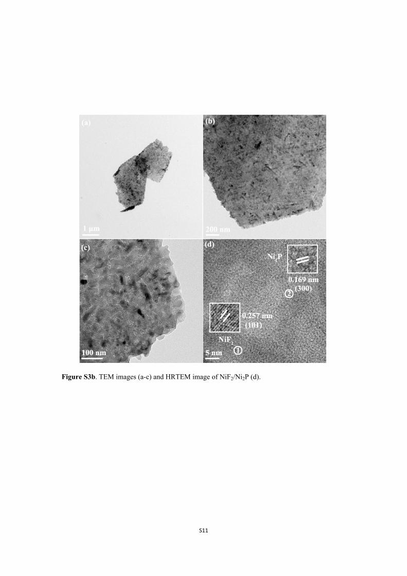
Figure S3b. TEM images (a-c) and HRTEM image of NiF2/Ni2P (d).
Page 12
S12
Figure S3c. HRTEM image of NiF2/Ni2P.
Page 13
S13
1.1 1.2 1.3 1.4 1.5 1.6 1.7
0
20
40
60
80
283 mV 317 mV
Potential (V vs. RHE)
Curr
ent d
ensit
y (m
A cm
-2)
NiF2/Ni2P + carbon pure NiF2/Ni2P pure carbon
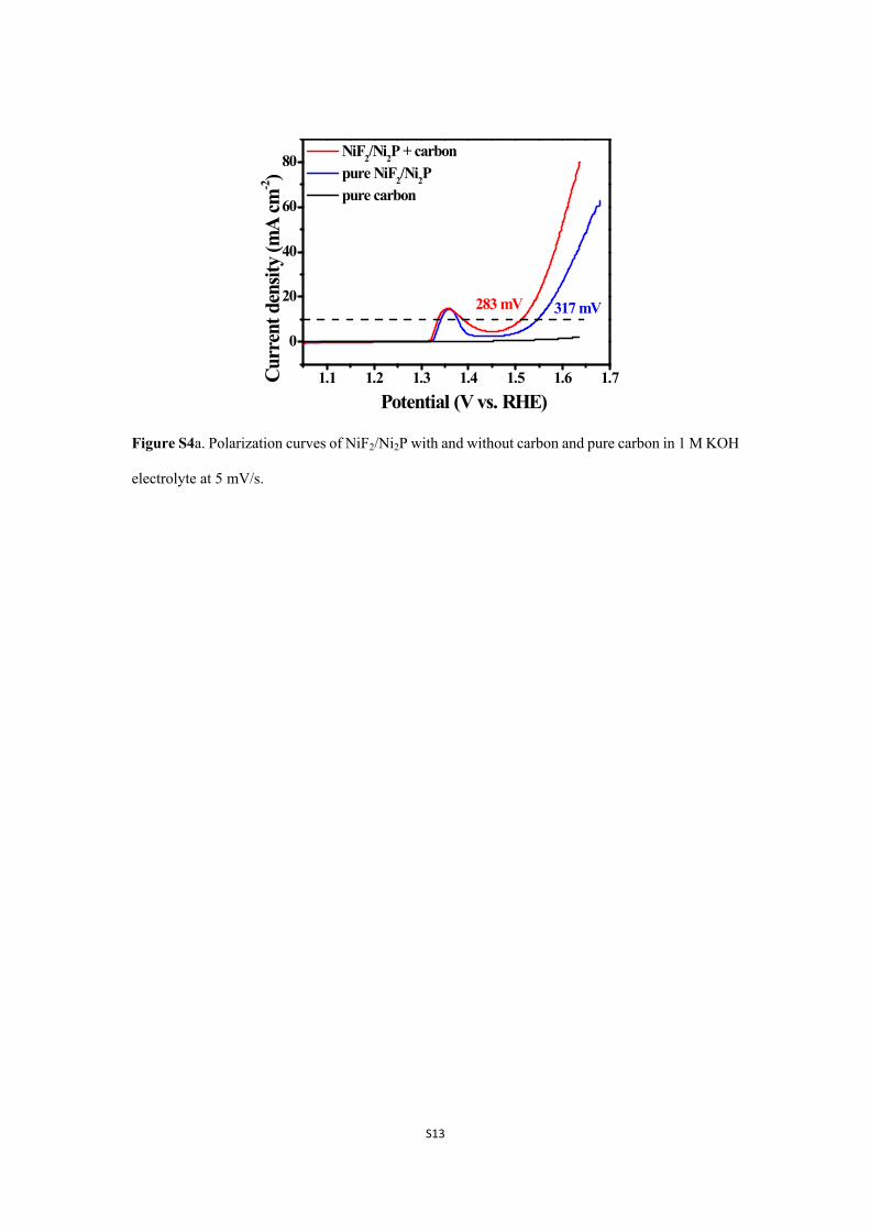
Figure S4a. Polarization curves of NiF2/Ni2P with and without carbon and pure carbon in 1 M KOH
electrolyte at 5 mV/s.
Page 14
S14
RS
R0 Rct
CPE2CPECPE1
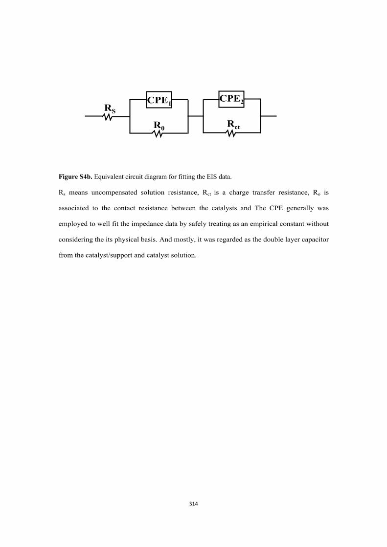
Figure S4b. Equivalent circuit diagram for fitting the EIS data.
Rs means uncompensated solution resistance, Rct is a charge transfer resistance, Ro is
associated to the contact resistance between the catalysts and The CPE generally was
employed to well fit the impedance data by safely treating as an empirical constant without
considering the its physical basis. And mostly, it was regarded as the double layer capacitor
from the catalyst/support and catalyst solution.
Page 15
S15
0.85 0.90 0.95 1.00 1.05
-0.06
-0.04
-0.02
0.00
0.02
0.04
0.06(a)
Curr
ent d
ensit
y(m
A cm
-2)
Potential (V vs. RHE)
10mV/s 20mV/s 30mV/s 40mV/s 50mV/s
0.85 0.90 0.95 1.00 1.05
-0.03
-0.02
-0.01
0.00
0.01
0.02
0.03
Curr
ent d
ensit
y(m
A cm
-2)
Potential (V vs. RHE)
10mV/s 20mV/s 30mV/s 40mV/s 50mV/s
(b)
0.85 0.90 0.95 1.00 1.05-0.08
-0.06
-0.04
-0.02
0.00
0.02
0.04
0.06(c)
Potential (V vs. RHE)
Curr
ent d
ensit
y(m
A cm
-2)
10mV/s 20mV/s 30mV/s 40mV/s 50mV/s
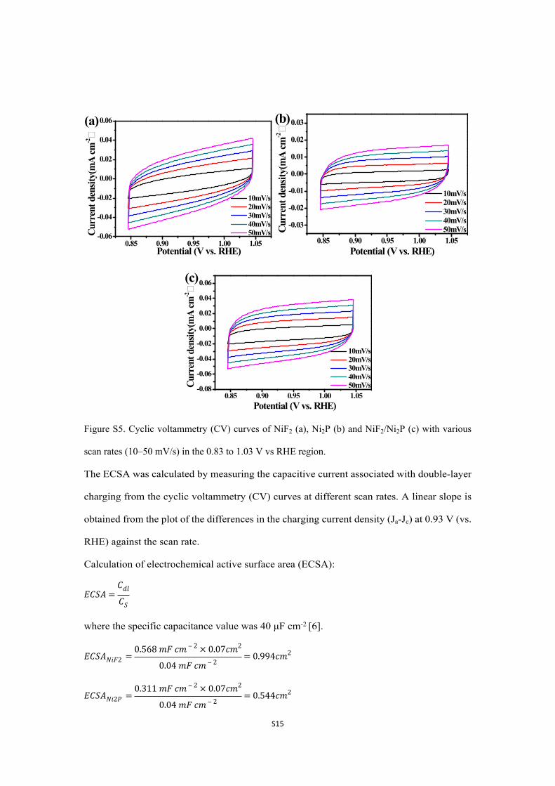
Figure S5. Cyclic voltammetry (CV) curves of NiF2 (a), Ni2P (b) and NiF2/Ni2P (c) with various
scan rates (10–50 mV/s) in the 0.83 to 1.03 V vs RHE region.
The ECSA was calculated by measuring the capacitive current associated with double-layer
charging from the cyclic voltammetry (CV) curves at different scan rates. A linear slope is
obtained from the plot of the differences in the charging current density (Ja-Jc) at 0.93 V (vs.
RHE) against the scan rate.
Calculation of electrochemical active surface area (ECSA):
𝐸𝐶𝑆𝐴 =𝐶𝑑𝑙
𝐶𝑆
where the specific capacitance value was 40 μF cm-2 [6].
𝐸𝐶𝑆𝐴𝑁𝑖𝐹2 =0.568 𝑚𝐹 𝑐𝑚 ‒ 2 × 0.07𝑐𝑚2
0.04 𝑚𝐹 𝑐𝑚 ‒ 2= 0.994𝑐𝑚2
𝐸𝐶𝑆𝐴𝑁𝑖2𝑃 =0.311 𝑚𝐹 𝑐𝑚 ‒ 2 × 0.07𝑐𝑚2
0.04 𝑚𝐹 𝑐𝑚 ‒ 2= 0.544𝑐𝑚2
Page 16
S16
𝐸𝐶𝑆𝐴𝑁𝑖𝐹2/𝑁𝑖2𝑃 =0.692 𝑚𝐹 𝑐𝑚 ‒ 2 × 0.07𝑐𝑚2
0.04 𝑚𝐹 𝑐𝑚 ‒ 2= 1.211𝑐𝑚2
Roughness Factor (RF) [7]:
𝑅𝑜𝑢𝑔ℎ𝑛𝑒𝑠𝑠 𝐹𝑎𝑐𝑡𝑜𝑟 (𝑅𝐹) =𝐸𝑙𝑒𝑐𝑡𝑟𝑜𝑐ℎ𝑒𝑚𝑖𝑐𝑎𝑙 𝑠𝑢𝑟𝑓𝑎𝑐𝑒 𝑎𝑟𝑒𝑎 (𝐸𝐶𝑆𝐴)
𝐺𝑒𝑜𝑚𝑒𝑡𝑟𝑖𝑐𝑎𝑙 𝑠𝑢𝑟𝑓𝑎𝑐𝑒 𝑎𝑟𝑒𝑎 (𝐺𝑆𝐴)
𝑅𝐹𝑁𝑖𝐹2 =0.994𝑐𝑚2
0.07𝑐𝑚2= 14.2
𝑅𝐹𝑁𝑖2𝑃 =0.544𝑐𝑚2
0.07𝑐𝑚2= 7.77
𝑅𝐹𝑁𝑖𝐹2/𝑁𝑖2𝑃 =1.211𝑐𝑚2
0.07𝑐𝑚2= 17.3
Page 17
S17
1.1 1.2 1.3 1.4 1.5 1.6 1.7
0.00
0.02
0.04 NiF2
Ni2P NiF2/Ni2P
Potential (V vs. RHE)
TOF
/S-1
350 mV
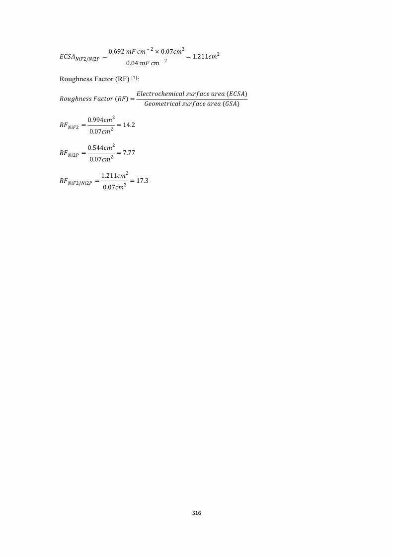
Figure S6. The turnover frequency curve for NiF2, Ni2P and NiF2/Ni2P.
Page 18
S18
0 10 20 30 40 50 600.00
0.05
0.10
0.15
V O2 (
mL)
Time (min)
Experimental Theoretical
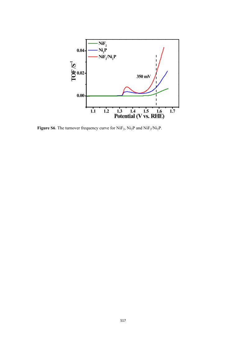
Figure S7. Faradaic efficiency of NiF2/Ni2P. The amount of O2 produced during the electrolysis
matches well with the theoretic amount of O2 generated assuming four electrons transferred for one
oxygen indicating a nearly 100% current efficiency.
Page 19
S19
0 1 2 3 4 5 6Time (min)
Inte
nsity
O2
H2
Experimental spectrum
Reference spectrum
(a)
0 5 10 15 20 25 30 35 400
100
200
300
400
500
600(b)
Concentration /%
Peak
are
a
y=15.15851x-6.22164R2=0.99961
H2
fitting line
5 10 15 20 25 30
40
80
120
160
200(c)y=6.63476x-2.00365R2=0.99861
O2
fitting line
Peak
are
a
Concentration /%
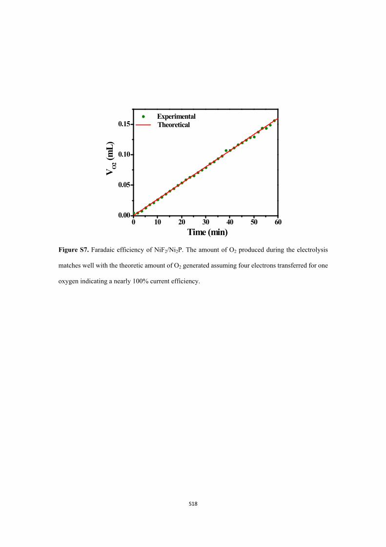
Figure S8. Purity of the gas obtained from water splitting measured by gas chromatography
spectrum (a). Calibration curves for H2 (b) and O2 (c).
Page 20
S20
1.1 1.2 1.3 1.4 1.5
0
5
10
15
20
25
30
Potential (V vs. RHE)
(a)
Curr
ent d
ensit
y (m
A cm
-2)
1mV/s 2mV/s 5mV/s 10mV/s
1.1 1.2 1.3 1.4 1.50
102030405060708090
100110120(b) 1mV/s
2mV/s 5mV/s 10mV/s
Curr
ent d
ensit
y (m
A cm
-2)
Potential (V vs. RHE)
1.0 1.5 2.0 2.5 3.0 3.5
20
40
60
80
100
120
140
160slope 45.10
slope 32.67
I p / (m
A cm
-2)
V1/2/(mV s-1)1/2
NiF2
Ni2P NiF2/Ni2P fitting line
slope 3.30
(c)
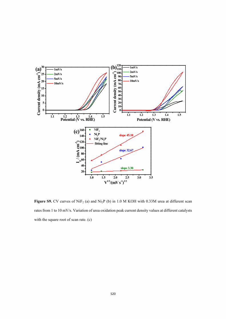
Figure S9. CV curves of NiF2 (a) and Ni2P (b) in 1.0 M KOH with 0.33M urea at different scan
rates from 1 to 10 mV/s. Variation of urea oxidation peak current density values at different catalysts
with the square root of scan rate. (c)
Page 21
S21
1.1 1.2 1.3 1.4 1.5
0
40
80
120
160
0.01M Urea 0.05M 0.1M 0.33M 0.6M
1MKOH+ Urea(a)
Curr
ent d
ensit
y (m
A cm
-2)
Potential (V vs. RHE)
NiF2/Ni2P
1.1 1.2 1.3 1.4 1.5
0
50
100
150
200(b)
Potential (V vs. RHE)
Curr
ent d
ensit
y (m
A cm
-2) KOH+0.33M Urea
NiF2/Ni2P
0.1M KOH 0.5M 1M 2M
Figure S10. Effect of urea concentrations on the electrocatalytic oxidation of urea at NiF2/Ni2P
electrode in 1M KOH at a scan rate of 10 mV/s, the concentration of urea used was (1) 0.01 M, (2)
0.05 M, (3) 0.1 M, (4) 0.33 M, (5) 0.66M.(a) Effect of KOH concentrations on the electrocatalytic
oxidation of urea at NiF2/Ni2P electrode in 0.33 M urea at a scan rate of 10 mV/s, the concentration
of KOH used was (1) 0.1 M, (2) 0.5 M, (3) 1 M, (4) 2 M.(b)
The reaction kinetics for urea oxidation was relevant to the concentration of urea and OH-. The
effect of urea concentration from 0.01 to 0.66 M in 1M KOH electrolyte was investigated for urea
oxidation. As can be seen, increasing the concentration of urea gave rise to larger activity until
concentrations of 0.33 M. The activity was not improved further by increasing the concentration
from 0.33 to 0.66 M. The urea oxidation peak was clearly observed due to the insufficient urea
(from 0.01 to 0.1 M) available for the reaction, thus a broad oxidation peak was found in the forward
scan direction and no such high oxidation current was found in the backward scan direction.
Sufficient urea was available for the active sites by increasing urea concentration to 0.33M, a similar
oxidation current was obtained for the forward and backward scan direction. When the urea
concentration reached 0.66 M, the local surface coverage of the Ni catalyst by excess urea and
reaction products will restrict the contact with OH- as the OH- is required for the formation of
NiOOH, the active catalyst for UOR. Thus the performance was reduced. Similar case was found
on the effect of KOH concentrations. The performance of urea oxidation was increased by
increasing the KOH concentration and it can be attributed to the increased ion conductivity and
NiOOH active sites for the reaction. By increasing the KOH concentration, more active sites of
NiOOH can be formed, the improved catalytic performance like higher oxidation current and
reduced onset potential was found.[8, 9]
Page 22
S22
0 1 2 3 4 5 6
Experimental spectrum
Reference spectrumN2H2
Time (min)
Inte
nsity
(a)
5 10 15 20 25 30
50
100
150
200
250
300
350
y=11.60425x-7.62138R2=0.99968
Peak
are
a
Concentration /%
N2
fitting line
(b)
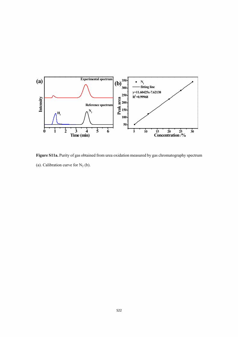
Figure S11a. Purity of gas obtained from urea oxidation measured by gas chromatography spectrum
(a). Calibration curve for N2 (b).
Page 23
S23
1.4 1.5 1.6 1.7 1.80.0
0.2
0.4
0.6
0.8
1.0
0
20
40
60
801.52V
1.35V
KOH KOH+Urea
Potential (V)
Curr
ent d
ensit
y (m
A cm
-2)
Cur
rent
ratio
of u
rea
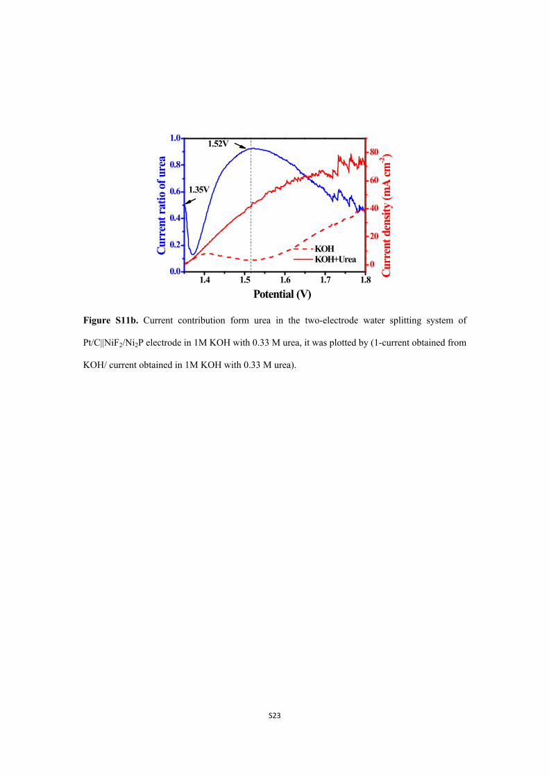
Figure S11b. Current contribution form urea in the two-electrode water splitting system of
Pt/C||NiF2/Ni2P electrode in 1M KOH with 0.33 M urea, it was plotted by (1-current obtained from
KOH/ current obtained in 1M KOH with 0.33 M urea).
Page 24
S24
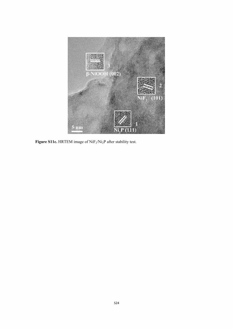
Figure S11c. HRTEM image of NiF2/Ni2P after stability test.
Page 25
S25
Table S1. The binding energy of Ni 2p components for all samples.
Binding energy/eVCatalysts
Ni 2p1/2 satellite Ni 2p3/2 satellite
NiF2 875.6 863.4 857.6 881.3
Ni2P 870.1 874.7 862.5 852.9 856.7 880.8
NiF2/Ni2P 870.1 875.6 863.2 852.9 857.6 881.3
Page 26
S26
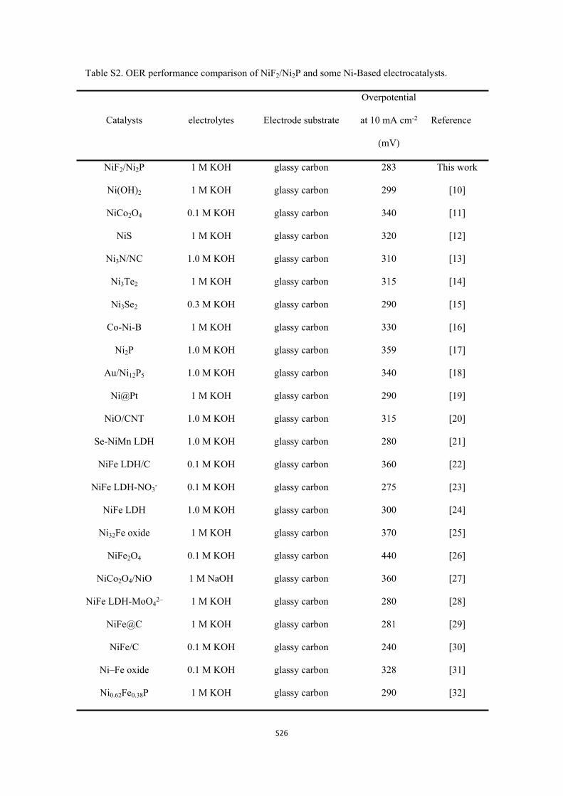
Table S2. OER performance comparison of NiF2/Ni2P and some Ni-Based electrocatalysts.
Catalysts electrolytes Electrode substrate
Overpotential
at 10 mA cm-2
(mV)
Reference
NiF2/Ni2P 1 M KOH glassy carbon 283 This work
Ni(OH)2 1 M KOH glassy carbon 299 [10]
NiCo2O4 0.1 M KOH glassy carbon 340 [11]
NiS 1 M KOH glassy carbon 320 [12]
Ni3N/NC 1.0 M KOH glassy carbon 310 [13]
Ni3Te2 1 M KOH glassy carbon 315 [14]
Ni3Se2 0.3 M KOH glassy carbon 290 [15]
Co-Ni-B 1 M KOH glassy carbon 330 [16]
Ni2P 1.0 M KOH glassy carbon 359 [17]
Au/Ni12P5 1.0 M KOH glassy carbon 340 [18]
Ni@Pt 1 M KOH glassy carbon 290 [19]
NiO/CNT 1.0 M KOH glassy carbon 315 [20]
Se-NiMn LDH 1.0 M KOH glassy carbon 280 [21]
NiFe LDH/C 0.1 M KOH glassy carbon 360 [22]
NiFe LDH-NO3- 0.1 M KOH glassy carbon 275 [23]
NiFe LDH 1.0 M KOH glassy carbon 300 [24]
Ni32Fe oxide 1 M KOH glassy carbon 370 [25]
NiFe2O4 0.1 M KOH glassy carbon 440 [26]
NiCo2O4/NiO 1 M NaOH glassy carbon 360 [27]
NiFe LDH-MoO42– 1 M KOH glassy carbon 280 [28]
NiFe@C 1 M KOH glassy carbon 281 [29]
NiFe/C 0.1 M KOH glassy carbon 240 [30]
Ni–Fe oxide 0.1 M KOH glassy carbon 328 [31]
Ni0.62Fe0.38P 1 M KOH glassy carbon 290 [32]
Page 27
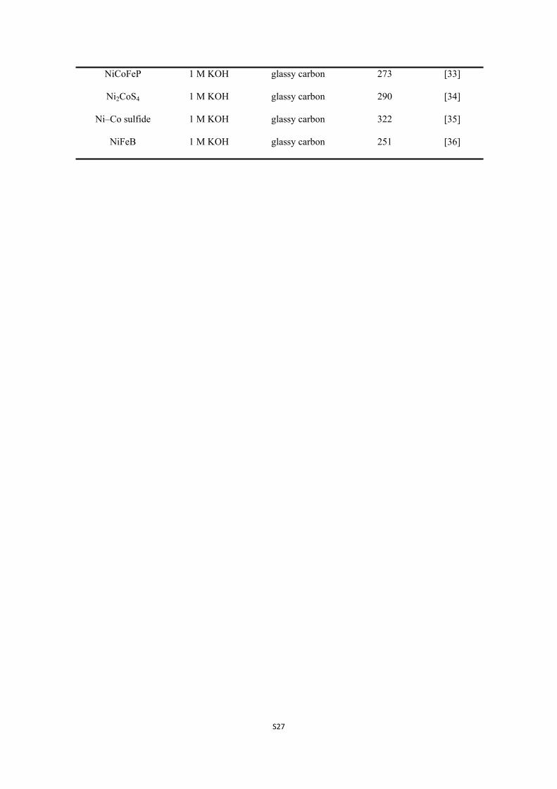
S27
NiCoFeP 1 M KOH glassy carbon 273 [33]
Ni2CoS4 1 M KOH glassy carbon 290 [34]
Ni–Co sulfide 1 M KOH glassy carbon 322 [35]
NiFeB 1 M KOH glassy carbon 251 [36]
Page 28
S28
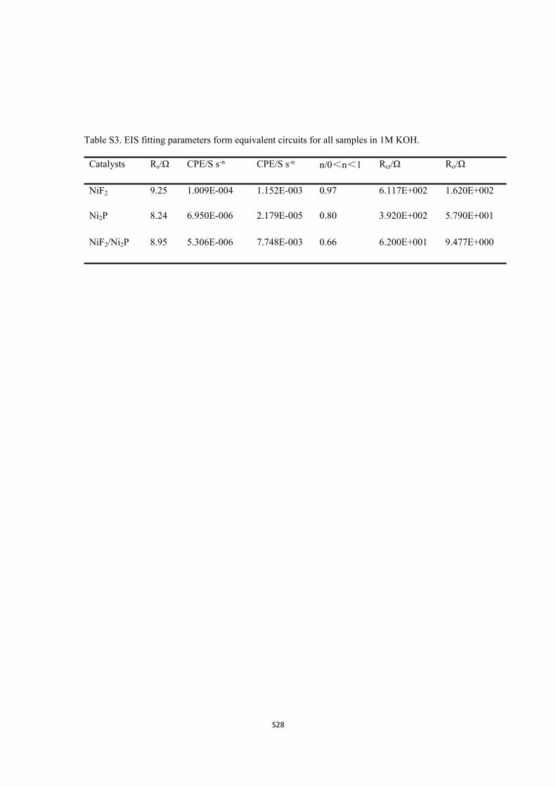
Table S3. EIS fitting parameters form equivalent circuits for all samples in 1M KOH.
Catalysts Rs/Ω CPE/S s-n CPE/S s-n n/0<n<1 Rct/Ω Ro/Ω
NiF2 9.25 1.009E-004 1.152E-003 0.97 6.117E+002 1.620E+002
Ni2P 8.24 6.950E-006 2.179E-005 0.80 3.920E+002 5.790E+001
NiF2/Ni2P 8.95 5.306E-006 7.748E-003 0.66 6.200E+001 9.477E+000
Page 29
S29
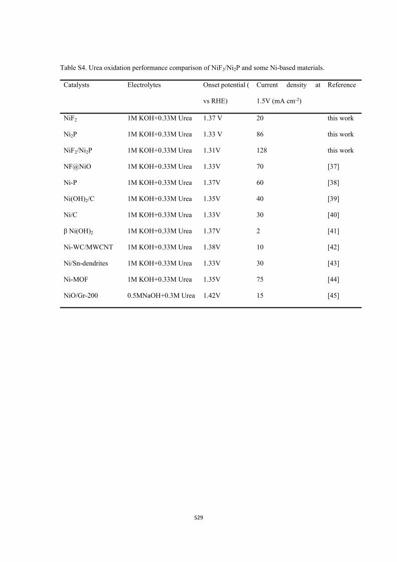
Table S4. Urea oxidation performance comparison of NiF2/Ni2P and some Ni-based materials.
Catalysts Electrolytes Onset potential (
vs RHE)
Current density at
1.5V (mA cm-2)
Reference
NiF2 1M KOH+0.33M Urea 1.37 V 20 this work
Ni2P 1M KOH+0.33M Urea 1.33 V 86 this work
NiF2/Ni2P 1M KOH+0.33M Urea 1.31V 128 this work
NF@NiO 1M KOH+0.33M Urea 1.33V 70 [37]
Ni-P 1M KOH+0.33M Urea 1.37V 60 [38]
Ni(OH)2/C 1M KOH+0.33M Urea 1.35V 40 [39]
Ni/C 1M KOH+0.33M Urea 1.33V 30 [40]
β Ni(OH)2 1M KOH+0.33M Urea 1.37V 2 [41]
Ni-WC/MWCNT 1M KOH+0.33M Urea 1.38V 10 [42]
Ni/Sn-dendrites 1M KOH+0.33M Urea 1.33V 30 [43]
Ni-MOF 1M KOH+0.33M Urea 1.35V 75 [44]
NiO/Gr-200 0.5MNaOH+0.3M Urea 1.42V 15 [45]
Page 30
S30
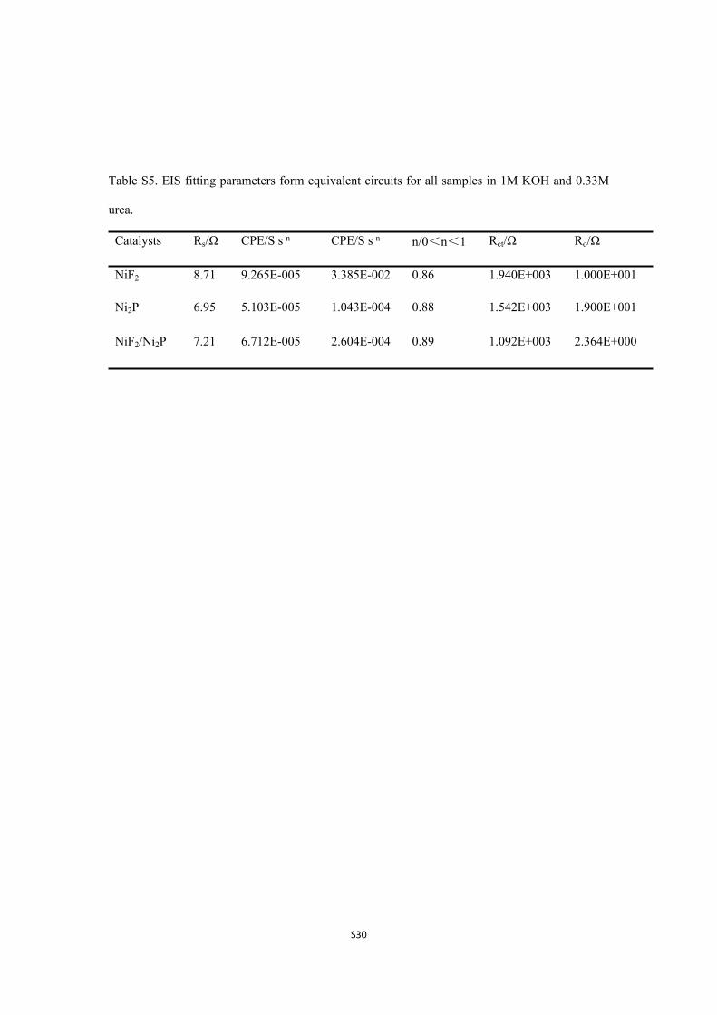
Table S5. EIS fitting parameters form equivalent circuits for all samples in 1M KOH and 0.33M
urea.
Catalysts Rs/Ω CPE/S s-n CPE/S s-n n/0<n<1 Rct/Ω Ro/Ω
NiF2 8.71 9.265E-005 3.385E-002 0.86 1.940E+003 1.000E+001
Ni2P 6.95 5.103E-005 1.043E-004 0.88 1.542E+003 1.900E+001
NiF2/Ni2P 7.21 6.712E-005 2.604E-004 0.89 1.092E+003 2.364E+000
Page 31
S31
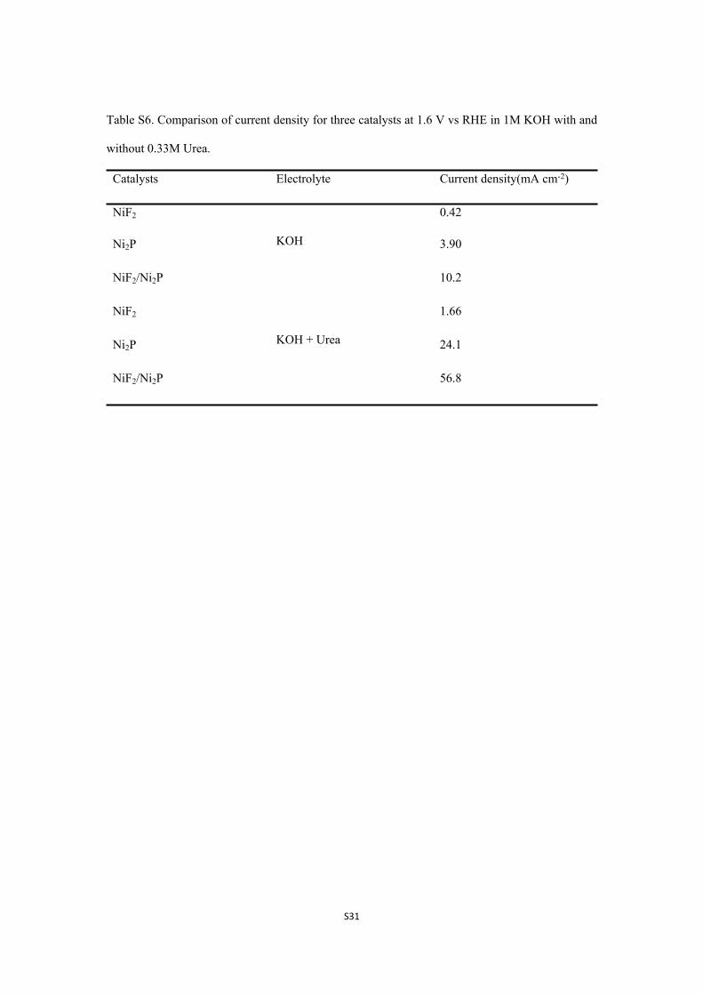
Table S6. Comparison of current density for three catalysts at 1.6 V vs RHE in 1M KOH with and
without 0.33M Urea.
Catalysts Electrolyte Current density(mA cm-2)
NiF2 0.42
Ni2P 3.90
NiF2/Ni2P
KOH
10.2
NiF2 1.66
Ni2P 24.1
NiF2/Ni2P
KOH + Urea
56.8
Page 32
S32
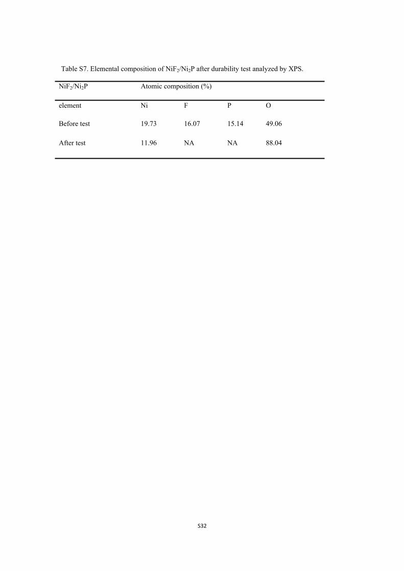
Table S7. Elemental composition of NiF2/Ni2P after durability test analyzed by XPS.
NiF2/Ni2P Atomic composition (%)
element Ni F P O
Before test 19.73 16.07 15.14 49.06
After test 11.96 NA NA 88.04
Page 33
S33
References
[1] J. Chun, C. Jo, S. Sahgong, M.G. Kim, E. Lim, D.H. Kim, J. Hwang, E. Kang, K.A. Ryu, Y.S. Jung, Y. Kim, J.
Lee, Ammonium Fluoride Mediated Synthesis of Anhydrous Metal Fluoride–Mesoporous Carbon Nanocomposites
for High-Performance Lithium Ion Battery Cathodes, ACS Appl Mater Interfaces, 2016, 8, 35180-35190.
[2] R. Prins, M.E. Bussell, Metal Phosphides: Preparation, Characterization and Catalytic Reactivity, Catal Lett,
2012, 142, 1413-1436.
[3] T. Zhou, Z. Cao, P. Zhang, H. Ma, Z. Gao, H. Wang, Y. Lu, J. He, Y. Zhao, Transition metal ions regulated
oxygen evolution reaction performance of Ni-based hydroxides hierarchical nanoarrays, Sci. Rep., 2017, 7, 46154.
[4] M. Gao, W. Sheng, Z. Zhuang, Q. Fang, S. Gu, J. Jiang, Y. Yan, Efficient Water Oxidation Using Nanostructured
α-Nickel-Hydroxide as an Electrocatalyst, J Am Chem Soc, 2014, 136, 7077-7084.
[5] J. Wang, K. Li, H.-x. Zhong, D. Xu, Z.-l. Wang, Z. Jiang, Z.-j. Wu, X.-b. Zhang, Synergistic effect between
metal-nitrogen-carbon sheets and NiO nanoparticles for enhanced electrochemical water-oxidation performance,
Angew. Chem. Int. Ed., 2015, 54, 10530-10534.
[6] B. Zhao, R. Ran, L. Sun, Z. Yang, X. Wu, D. Weng, A high-surface-area La-Ce-Mn mixed oxide with enhanced
activity for CO and C3H8 oxidation, Catal. Commun., 2018, 105, 26-30.
[7] C.C.L. McCrory, S. Jung, J.C. Peters, T.F. Jaramillo, Benchmarking Heterogeneous Electrocatalysts for the
Oxygen Evolution Reaction, J. Am. Chem. Soc., 2013, 135, 16977-16987.
[8] R.P. Forslund, J.T. Mefford, W.G. Hardin, C.T. Alexander, K.P. Johnston, K.J. Stevenson, Nanostructured
LaNiO3 Perovskite Electrocatalyst for Enhanced Urea Oxidation, ACS Catal., 2016, 6, 5044-5051.
[9] R.M. Tesfaye, G. Das, B.J. Park, J. Kim, H.H. Yoon, Ni-Co bimetal decorated carbon nanotube aerogel as an
efficient anode catalyst in urea fuel cells, Sci. Rep., 2019, 9, 479.
[10] L.-A. Stern, X. Hu, Enhanced oxygen evolution activity by NiOx and Ni(OH)2 nanoparticles, Faraday Discuss,
2014, 176, 363-379.
[11] X. Lv, Y. Zhu, H. Jiang, X. Yang, Y. Liu, Y. Su, J. Huang, Y. Yao, C. Li, Hollow mesoporous NiCo2O4
nanocages as efficient electrocatalysts for oxygen evolution reaction, Dalton Trans., 2015, 44, 4148-4154.
[12] P. Luo, H. Zhang, L. Liu, Y. Zhang, J. Deng, C. Xu, N. Hu, Y. Wang, Targeted synthesis of unique Nickel
sulfide (NiS, NiS2) microarchitectures and the applications for the enhanced water splitting system, ACS Appl.
Mater. Interfaces, 2017, 9, 2500-2508.
[13] M. Chen, J. Qi, D. Guo, H. Lei, W. Zhang, R. Cao, Facile synthesis of sponge-like Ni3N/NC for electrocatalytic
water oxidation, Chem. Commun., 2017, 53, 9566-9569.
[14] Z. Wang, L. Zhang, Nickel Ditelluride Nanosheet Arrays: A Highly Efficient Electrocatalyst for the Oxygen
Evolution Reaction, ChemElectroChem, 2018, 5, 1153-1158.
[15] A.T. Swesi, J. Masud, M. Nath, Nickel selenide as a high-efficiency catalyst for oxygen evolution reaction,
Energy Environ. Sci., 2016, 9, 1771-1782.
[16] J. Zhang, X. Li, Y. Liu, Z. Zeng, X. Cheng, Y. Wang, W. Tu, M. Pan, Bi-metallic boride electrocatalysts with
enhanced activity for the oxygen evolution reaction, Nanoscale, 2018, 10, 11997-12002.
[17] H. Sun, X. Xu, Z. Yan, X. Chen, F. Cheng, P.S. Weiss, J. Chen, Porous multishelled Ni2P hollow microspheres
as an active electrocatalyst for hydrogen and oxygen evolution, Chem. Mater., 2017, 29, 8539-8547.
[18] Y. Xu, S. Duan, H. Li, M. Yang, S. Wang, X. Wang, R. Wang, Au/Ni12P5 core/shell single-crystal nanoparticles
as oxygen evolution reaction catalyst, Nano Research, 2017, 10, 3103-3112.
[19] F. Wang, G. Chen, X. Liu, F. Chen, H. Wan, L. Ni, N. Zhang, R. Ma, G. Qiu, Advanced Electrocatalytic
Performance of Ni-Based Materials for Oxygen Evolution Reaction, Acs Sustain Chem Eng, 2019, 7, 341-349.
[20] Y. Fan, Y. Wu, G. Clavel, M.H. Raza, P. Amsalem, N. Koch, N. Pinna, Optimization of the Activity of Ni-
Based Nanostructures for the Oxygen Evolution Reaction, ACS Appl. Energy Mater., 2018, 1, 4554-4563.
Page 34
S34
[21] J. Du, Z. Zou, A. Yu, C. Xu, Selenization of NiMn-layered double hydroxide with enhanced electrocatalytic
activity for oxygen evolution, Dalton Trans., 2018, 47, 7492-7497.
[22] F. Dionigi, T. Reier, Z. Pawolek, M. Gliech, P. Strasser, Design Criteria, Operating Conditions, and Nickel–
Iron Hydroxide Catalyst Materials for Selective Seawater Electrolysis, ChemSusChem, 2016, 9, 962-972.
[23] Y. Xu, Y. Hao, G. Zhang, Z. Lu, S. Han, Y. Li, X. Sun, Room-temperature synthetic NiFe layered double
hydroxide with different anions intercalation as an excellent oxygen evolution catalyst, RSC Adv, 2015, 5, 55131-
55135.
[24] F. Song, X. Hu, Exfoliation of layered double hydroxides for enhanced oxygen evolution catalysis, Nat
Commun, 2014, 5, 4477.
[25] M. Yu, G. Moon, E. Bill, H. Tueysuez, Optimizing Ni-Fe Oxide Electrocatalysts for Oxygen Evolution Reaction
by Using Hard Templating as a Toolbox, ACS Appl. Energy Mater., 2019, 2, 1199-1209.
[26] M. Li, W. Wang, M. Yang, F. Lv, L. Cao, Y. Tang, R. Sun, Z. Lu, Large-scale fabrication of porous carbon-
decorated iron oxide microcuboids from Fe-MOF as high-performance anode materials for lithium-ion batteries, Rsc
Adv., 2015, 5, 7356-7362.
[27] C. Mahala, M. Basu, Nanosheets of NiCo2O4/NiO as Efficient and Stable Electrocatalyst for Oxygen Evolution
Reaction, ACS Omega, 2017, 2, 7559-7567.
[28] N. Han, F. Zhao, Y. Li, Ultrathin nickel–iron layered double hydroxide nanosheets intercalated with molybdate
anions for electrocatalytic water oxidation, J Mater Chem A, 2015, 3, 16348-16353.
[29] Y. Feng, X.-Y. Yu, U. Paik, N-doped graphene layers encapsulated NiFe alloy nanoparticles derived from
MOFs with superior electrochemical performance for oxygen evolution reaction, Sci. Rep., 2016, 6, 34004.
[30] Y. Feng, H. Zhang, Y. Zhang, X. Li, Y. Wang, Ultrathin Two-Dimensional Free-Standing Sandwiched NiFe/C
for High-Efficiency Oxygen Evolution Reaction, ACS Appl Mater Interfaces, 2015, 7, 9203-9210.
[31] J. Qi, W. Zhang, R. Xiang, K. Liu, H.-Y. Wang, M. Chen, Y. Han, R. Cao, Porous Nickel–Iron Oxide as a
Highly Efficient Electrocatalyst for Oxygen Evolution Reaction, Adv. Sci., 2015, 2, 1500199.
[32] H.-H. Zou, C.-Z. Yuan, H.-Y. Zou, T.-Y. Cheang, S.-J. Zhao, U.Y. Qazi, S.-L. Zhong, L. Wang, A.-W. Xu,
Bimetallic phosphide hollow nanocubes derived from a prussian-blue-analog used as high-performance catalysts for
the oxygen evolution reaction, Catal. Sci. Technol., 2017, 7, 1549-1555.
[33] Y. Guo, J. Tang, Z. Wang, Y. Sugahara, Y. Yamauchi, Hollow Porous Heterometallic Phosphide Nanocubes
for Enhanced Electrochemical Water Splitting, Small, 2018, 14, 1802442.
[34] Y.-R. Hong, S. Mhin, K.-M. Kim, W.-S. Han, H. Choi, G. Ali, K.Y. Chung, H.J. Lee, S.-I. Moon, S. Dutta, S.
Sun, Y.-G. Jung, T. Song, H. Han, Electrochemically activated cobalt nickel sulfide for an efficient oxygen evolution
reaction: partial amorphization and phase control, J Mater Chem A, 2019, 7, 3592-3602.
[35] Y.-R. Hong, S. Mhin, J. Kwon, W.-S. Han, T. Song, H. Han, Synthesis of transition metal sulfide and reduced
graphene oxide hybrids as efficient electrocatalysts for oxygen evolution reactions, R. Soc. Open Sci., 2018, 5,
180927.
[36] G. Liu, D. He, R. Yao, Y. Zhao, J. Li, Amorphous NiFeB nanoparticles realizing highly active and stable oxygen
evolving reaction for water splitting, Nano Res., 2018, 11, 1664-1675.
[37] M.-S. Wu, F.-Y. Chen, Y.-H. Lai, Y.-J. Sie, Electrocatalytic oxidation of urea in alkaline solution using
nickel/nickel oxide nanoparticles derived from nickel-organic framework, Electrochim Acta, 2017, 258, 167-174.
[38] R. Ding, X. Li, W. Shi, Q. Xu, L. Wang, H. Jiang, Z. Yang, E. Liu, Mesoporous Ni-P nanocatalysts for alkaline
urea electrooxidation, Electrochim Acta, 2016, 222, 455-462.
[39] D. Wang, S. Liu, Q. Gan, J. Tian, T.T. Isimjan, X. Yang, Two-dimensional nickel hydroxide nanosheets with
high-content of nickel (III) species towards superior urea electro-oxidation, J. Electroanal. Chem., 2018, 829, 81-87.
[40] L. Wang, L.T. Ren, X.R. Wang, X. Feng, J.W. Zhou, B. Wang, Multivariate MOF-Templated Pomegranate-
Like Ni/C as Efficient Bifunctional Electrocatalyst for Hydrogen Evolution and Urea Oxidation, ACS Appl Mater
Page 35
S35
Interfaces, 2018, 10, 4750-4756.
[41] R.K. Singh, A. Schechter, Electrochemical investigation of urea oxidation reaction on β Ni(OH)2 and
Ni/Ni(OH)2, Electrochim. Acta, 2018, 278, 405-411.
[42] L. Wang, T. Du, J. Cheng, X. Xie, B. Yang, M. Li, Enhanced activity of urea electrooxidation on nickel catalysts
supported on tungsten carbides/carbon nanotubes, J. Power Sources, 2015, 280, 550-554.
[43] R.K. Singh, P. Subramanian, A. Schechter, Enhanced Urea Activity of Oxidation on Nickel-Deposited Tin
Dendrites, ChemElectroChem, 2017, 4, 1037-1043.
[44] D.D. Zhu, C.X. Guo, J.L. Liu, L. Wang, Y. Dub, S.Z. Qiao, Two-dimensional metal-organic frameworks with
high oxidation states for efficient electrocatalytic urea oxidation, Chem Commun, 2017, 53, 10906-10909.
[45] R.M.A. Hameed, S.S. Medany, NiO nanoparticles on graphene nanosheets at different calcination temperatures
as effective electrocatalysts for urea electro-oxidation in alkaline medium, J Colloid Interf Sci, 2017, 508, 291-302.