Spare parts MT20-24 BOOK OF SPARE PARTS FOR HOOK LIFT TRAILERS TYPE MT20-24 Text table with the list of parts for the given team or mechanism is enclosed to each of the drawing To find the catalogue number for required part first you need to look at the picture of team or mechanism. Each part on the drawing has a number. These numbers you will find in the tables. By the order you have to give as follows: - full address of the buyer , - number of the part agree with the catalogue, - catalogue number - quantity of ordered parts, - the year of production and trailer’s serial number Drawings: 1. Draw.1 Table 1 – Main frame . 2. Draw. 2 Table 2 - Intermedia frame I. 3. Draw. 3 Table 3 - Intermedia farme II. 4. Draw. 4 Table 4 - Arm. 5. Draw. 5 Table 5 - Rocker left + right 6. Draw. 6a Table 6a – Hydraulic brake. 7. Draw. 6b Table 6b – Pneumatic brake ( 2-lines). 8. Draw. 6c Table 6c – Pneumatic brake (1-line). 9. Draw. 7 Table 7 - Hydraulic installation of lifting. 10. Draw. 8 Table 8 - Hydraulic installation of lock. 11. Draw. 9 Table 9 - Hydraulic installation of supports.. 12. Draw. 10a Table 10a – Hydraulic installation of advance of arm. 13. Draw. 10b Table 10b – Hydraulic installation of advance of arm with hydraulic blocking of container 14. Draw.11a Table 11a - Hydraulic blocking of container SS 3021. 15. Draw.11b Table 11b – Hydraulic blcoking of container DIN 30 722. 16. Draw.12 Table 12 – Hydraulic installation of wall of container 17. Draw.13 Table 13 – Hydraulic installation of torsional axle. 18. Draw.14 Table 14 – Hydraulic installation of distributor. 19. Draw.15 Table 15 – Power from traktor.. 20. Draw.16 Table 16 – Electric installation. 21. Draw.17 Table 17 – Steering installation. 22. Draw.18 Table 18 – Complete axle. 23. Draw.19 Table 19 – Spring susupension. 1
Transcript
Spare parts MT20-24
BOOK OF SPARE PARTS FOR HOOK LIFT TRAILERS TYPE MT20-24
Text table with the list of parts for the given team or mechanism is enclosed to each of the drawing To find the catalogue number for required part first you need to look at the picture of team or mechanism. Each part on the drawing has a number. These numbers you will find in the tables. By the order you have to give as follows: - full address of the buyer , - number of the part agree with the catalogue, - catalogue number - quantity of ordered parts, - the year of production and trailer’s serial number
Drawings:
1. Draw.1 Table 1 – Main frame . 2. Draw. 2 Table 2 - Intermedia frame I. 3. Draw. 3 Table 3 - Intermedia farme II. 4. Draw. 4 Table 4 - Arm. 5. Draw. 5 Table 5 - Rocker left + right 6. Draw. 6a Table 6a – Hydraulic brake. 7. Draw. 6b Table 6b – Pneumatic brake ( 2-lines). 8. Draw. 6c Table 6c – Pneumatic brake (1-line). 9. Draw. 7 Table 7 - Hydraulic installation of lifting. 10. Draw. 8 Table 8 - Hydraulic installation of lock. 11. Draw. 9 Table 9 - Hydraulic installation of supports.. 12. Draw. 10a Table 10a – Hydraulic installation of advance of arm. 13. Draw. 10b Table 10b – Hydraulic installation of advance of arm with hydraulic blocking of
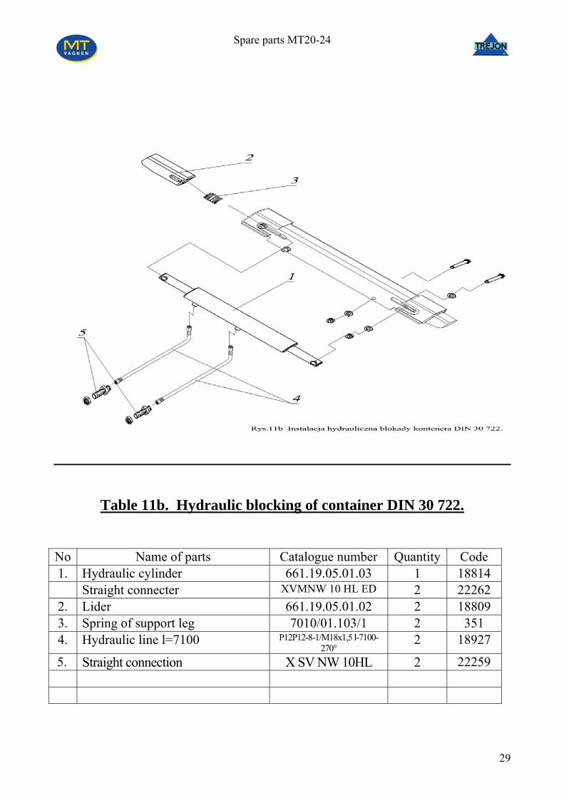
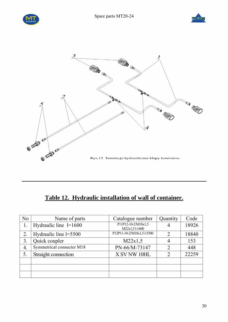
container 14. Draw.11a Table 11a - Hydraulic blocking of container SS 3021. 15. Draw.11b Table 11b – Hydraulic blcoking of container DIN 30 722. 16. Draw.12 Table 12 – Hydraulic installation of wall of container 17. Draw.13 Table 13 – Hydraulic installation of torsional axle. 18. Draw.14 Table 14 – Hydraulic installation of distributor. 19. Draw.15 Table 15 – Power from traktor.. 20. Draw.16 Table 16 – Electric installation. 21. Draw.17 Table 17 – Steering installation. 22. Draw.18 Table 18 – Complete axle. 23. Draw.19 Table 19 – Spring susupension.
1
Spare parts MT20-24
2
Spare parts MT20-24
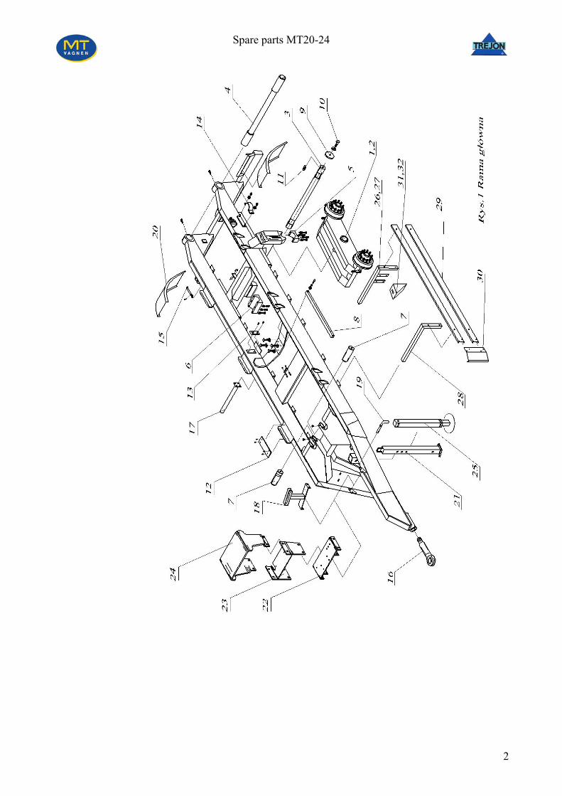
Table 1: Main frame. No Name fo part Catalogue number Quantity Code 1 Complete set of left rocker PH19/01.001 1 21346 2 Complete set of right rocker PH19/01.002 1 21347 3 Bolt of rocker PH19/01.003 1 21937 4 Complete set of back beam PH19/01.004 1 22229 5 Lower handle PH19/01.005 2 21282 6 Lower inside handle PH19/01.006 1 21287 7 Bolt of main cylinder PH16/01.006 2 4607 8 Support PH15/01.007 1 3356 9 Special washer PH19/01. 007 2 21619 10 Special screw PH19/01.008 2 21625 11 Prismatic inlet A28x16x80 DIN 6885-1 1 21626 12 Sliding plate I PH16/01.010 6 11153 13 Sliding plate II PH16/01.011 2 4480 14 Clamping ring of cylinder PH16/01.014 2 3226 15 Bolt of cylinder PH19/01.009 2 21700 16 Eye hitch ø 50 006634500 1 18499
Ball hitch 80 006639320 1 18498 17 Bracket of mudguards PH19/01.010 2 6863 18 Complete set of stand PH19/01.011 1 19903 19 Bolt of leg PH16/01.024 1 6380 20 Mudguards with handles 4/8 2877+356
21 Support leg PH16/01.005 1 3368 22 Stand PH19/01.012 1 18953 23 Stand PH19/01.013 1 20972 24 Cover PH19/01.014 1 18948 25 Hydraulic support leg PH19/01.015 1 14096 26 Right bracket I PH19/01.016 1 21812 27 Left bracket II PH19/01.017 1 21816 28 Bracket III PH19/01.018 2 21819 29 Sleeve PH19/01.019 4 21826 30 Frontal profile PH19/01.020 2 21828 31 Wedge of wheels - 2 1760 32 Shore of wedge - 2 2469
3
Spare parts MT20-24
4
Spare parts MT20-24
Table 2: Intermedia frame I
No Name of parts Catalque parts Quantity Code 1 Intermedia frame I PH16/02.001 1 11127 2 Complete roll PH16/02.002 2 10910 3 Cover of roll PH16/02.003 2 3945 4 Connective bolt PH16/02.004 1 4610 5 Buckling beam PH16/02.005 1 4614 6 Sliding bush I PH16/02.006 2 1955 7 Bracket of lock PH16/02.007 1 4617 8 Spring of lock PH16/02.008 1 9522 9 Bolt of lock PH16/02.009 1 11130
5
Spare parts MT20-24
6
Spare parts MT20-24
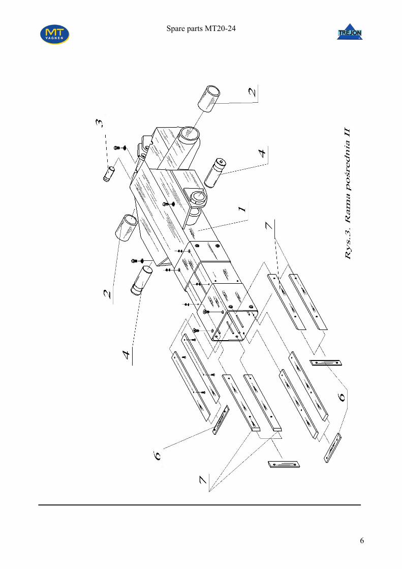
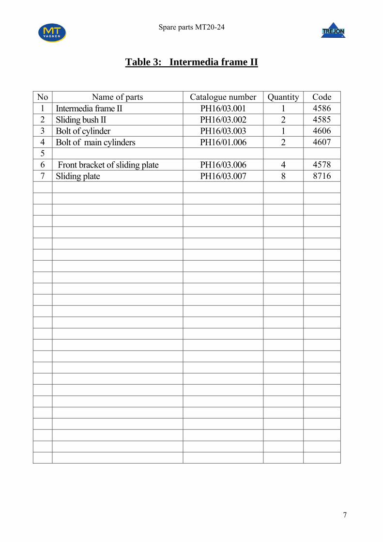
Table 3: Intermedia frame II
No Name of parts Catalogue number Quantity Code 1 Intermedia frame II PH16/03.001 1 4586 2 Sliding bush II PH16/03.002 2 4585 3 Bolt of cylinder PH16/03.003 1 4606 4 Bolt of main cylinders PH16/01.006 2 4607 5 6 Front bracket of sliding plate PH16/03.006 4 4578 7 Sliding plate PH16/03.007 8 8716
7
Spare parts MT20-24
8
Spare parts MT20-24
Table 4: Arm
No Name of parts Catalogue number Quantity Code 1 Arm of hook PH19/04.001 1 19891 2 Bolt of cylinder PH16/04.002 1 4605 3 Cover of bolt PH16/04.003 2 4608 4 Hook PH16/04.004 1 3359 5 Sliding plate PH16/04.005 4 8718 OPTIONS
6 Hook for containers DIN 30722 PH19/04.002 1 21134 7 Hook for containers SS 3021 PH19/04.003 1 22286 8 Complete claw PH19/04.004 1 21138 9 Bolt PH19/04.005 1 21141
9
Spare parts MT20-24
10
Spare parts MT20-24
Table 5: Left + right rocker
No Name of parts Catalogue number Quantity Code 1 Rocker PH19/01.001/2 1/1 21346/21347
2 Cylindrical bush PEL 100/120x100 2 21169 3 Drum PH16/05.003 2 4 Expander PH16/05.004 2 5 Lever of expander PH16/05.005 2 6 Rest of distance PH16/05.006 2 7 Back conic bearing PH16/05.007 2 8 Front conic bearing PH16/05.008 2 9 Jaw with lining PH16/05.009 4 10 Spring PH16/05.010 4 11 Pin of wheel M22x1,5 PH16/05.011 20 12 Nut of pin of Wheel M22x1,5 Fe/Zn 5 PH16/05.012 20 13 Rest PH16/05.013 2 14 Castellated nut PH16/05.014 2 15 Cotter PH16/05.015 2 16 Calpack PH16/05.016 2 17 Tyre 550/60 x 22,5 fi 1235 mm - 4 18 Wheel band - 4
11
Spare parts MT20-24
12
Spare parts MT20-24
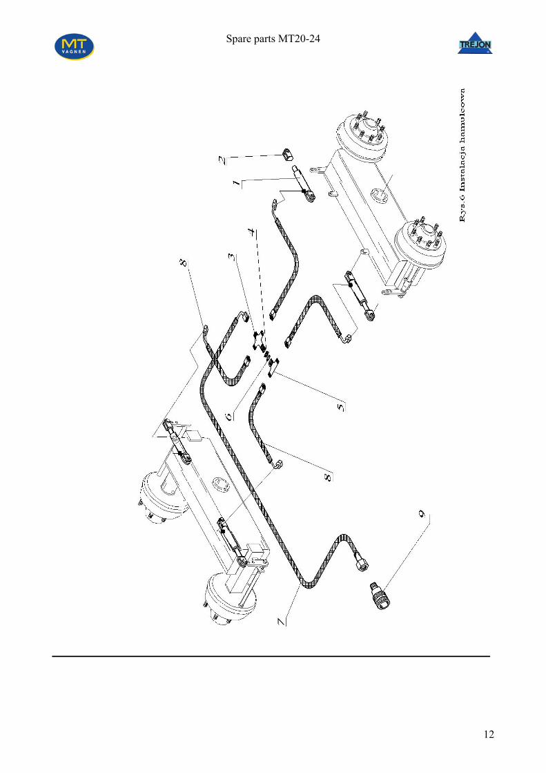
Table 6a: Hydraulic brake installation
No Name of parts Catalgue number Quantity Code 1 Hydraulic cylinder PH16/06.001 4 163 2 Fork of cylinder PH16/06.002 4 2522 3 Four way piece PH16/06.003 1 420 4 Short nut M22x1,5 PH16/06.004 1 1869 5 Special three way piece PH16/06.004 1 451 6 Copper basket PH16/06.004 1 1686 7 Hydraulic line l=7700 PH16/06.004 1 17760 8 Hydraulic line l=1100 PH16/06.004 4 17757 9 Brake quick-coupler PFT.1.1318.102 1 11629 10 11 12 13 14 15 16 17 18 19 20 21 22 23 24 25 26 27 28 29 30 31 32 33 34 35 36 37
13
Spare parts MT20-24
14
Spare parts MT20-24
Table 6b: Pneumatic brake installation. (2-lines)
No Name fo parts Catalogue number Quantity Code 1 Tympanic cylinder 24” 4 188 2 Main brake valve 44 12 011 0 1 4781 3 Air tank 60 l 1 253 4 Line-filter 81 10 010 0 2 520 5 Automatic connecter 87 10 030 0 1 198 6 Yellow air line 1 184 7 Straight connecter with long
thread M22/fi15 2 15423
8 Three way connecter fi15/fi15/fi15 1 15415 9 Knee conecter M22/fi15x12 4 15419 10 Knee conecter M16/fi15 2 15420 11 Spring of tympanic cylinder 4 370 12 Long fork of cylinder 2 284 13 Bolt of fork 4 14 Short fork of cylinder 2 2522 15 Control coupling M22 zew 1 15425 16 Drain valve 83 10 011 0 1 333 17 Screwed cork M22x1,5 1 1836 18 Straight connecter M22/fi15 M22/fi15 2 17844 19 Three way connecter M22/fi15/M22 2 15421 20 Regulator of power braking 1 4782 21 Paneumatic line Ø15x1,5 22 Connection of autoamtic line 87 15 030 0 1 208 23 Straight long connecter M22/M16/M22 1 15418 24 Connection automatic line 87 15 020 0 1 207 25 Connection of automatic line 87 10 020 0 1 195 26 Spiral red line 1 178 27 28 29 30 31 32 33 34 35 36 37
15
Spare parts MT20-24
16
Spare parts MT20-24
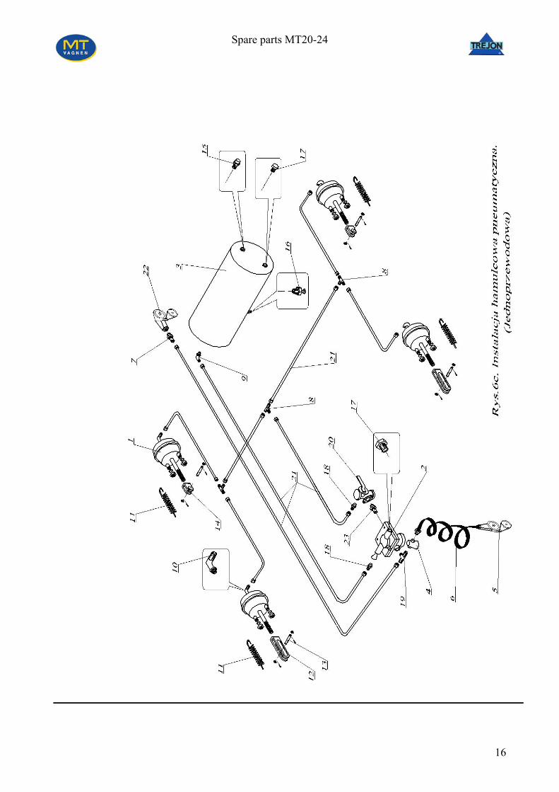
Table 6c: Pneumatic brake installation (1-line)
No Name of parts Catalogue number Quantity Code 1 Tympanic cylinder 24” 4 188 2 Main brake valve 44 12 011 0 1 4781 3 Air tank 60 l 1 253 4 Line- filter 81 10 010 0 2 520 5 Automatic connecter 87 10 030 0 1 198 6 Yellow air line 1 184 7 Straight connecter with long
thread M22/fi15 1 15423
8 Three way connecter fi15/fi15/fi15 1 15415 9 Knee connecter M22/fi15x12 4 15419 10 Knee connecter M16/fi15 2 15420 11 Spring of tympanie cylinder 4 370 12 Long fork of cylinder 2 284 13 Bolt of fork 4 14 Short fork of cylinder 2 2522 15 Control coupling M22 zew 1 15425 16 Dehydrating valve 83 10 011 0 1 333 17 Screwed cork M22x1,5 2 1836 18 Straight connecter M22/fi15 M22/fi15 2 17844 19 Three way connecter M22/fi15/M22 1 15421 20 Regulator of power braking 1 4782 21 Pneumatic line Ø15x1,5 22 Connection of automatic line 87 15 030 0 1 208 23 Straight long connecter M22/M16/M22 1 15418 24 25 26 27 28
17
Spare parts MT20-24
18
Spare parts MT20-24
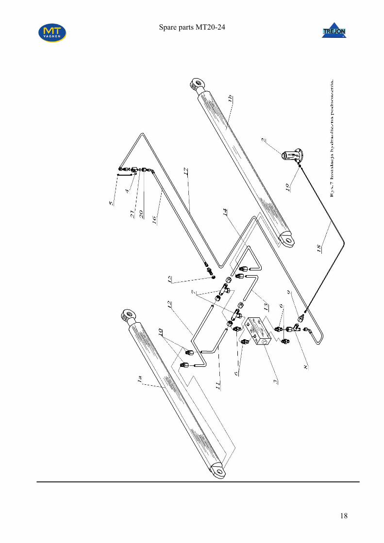
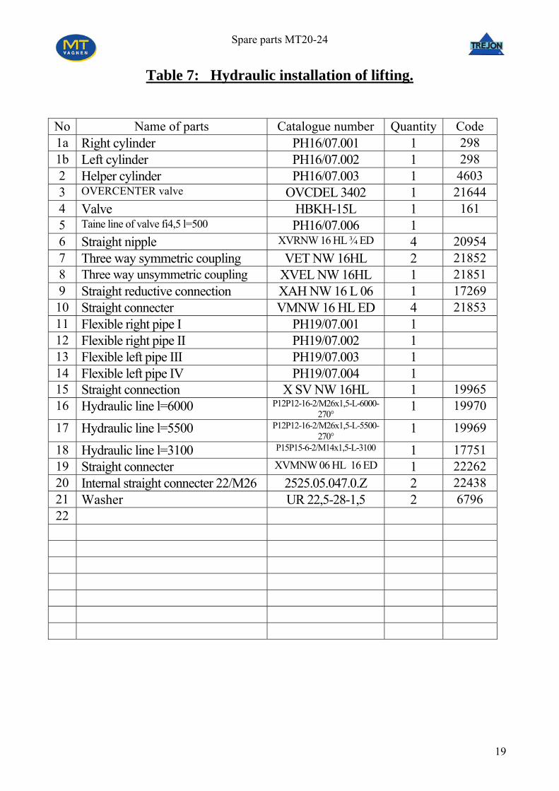
Table 7: Hydraulic installation of lifting.
No Name of parts Catalogue number Quantity Code 1a Right cylinder PH16/07.001 1 298 1b Left cylinder PH16/07.002 1 298 2 Helper cylinder PH16/07.003 1 4603 3 OVERCENTER valve OVCDEL 3402 1 21644 4 Valve HBKH-15L 1 161 5 Taine line of valve fi4,5 l=500 PH16/07.006 1 6 Straight nipple XVRNW 16 HL ¾ ED 4 20954 7 Three way symmetric coupling VET NW 16HL 2 21852 8 Three way unsymmetric coupling XVEL NW 16HL 1 21851 9 Straight reductive connection XAH NW 16 L 06 1 17269 10 Straight connecter VMNW 16 HL ED 4 21853 11 Flexible right pipe I PH19/07.001 1 12 Flexible right pipe II PH19/07.002 1 13 Flexible left pipe III PH19/07.003 1 14 Flexible left pipe IV PH19/07.004 1 15 Straight connection X SV NW 16HL 1 19965 16 Hydraulic line l=6000 P12P12-16-2/M26x1,5-L-6000-
270° 1 19970
17 Hydraulic line l=5500 P12P12-16-2/M26x1,5-L-5500- 270°
o Name of parts Catalogue number Quantity Code NExtreme v1 alve VFC 38 1 21646
2 Identical valve VBD-L 38 1 21645 3 Cylinder of lock P H16/08.003 1 294 4 Straight connecter XV D MNW 10 HL 18E 2 22260 5 Straight connection XVRNW 10 HL ED 6 3064 6 7 Hydraulic line l=5500 P12P11-10-2/M 1,5 l-5500 18x 1 18840 8 Hydraulic line l=4100 P11P11-10-2/M18x1,5 l-4100 1 17756 9 Hydarulic line l=2600 P12P11-10-2/M18x1,5 l-2600 1 18841 10 Hydraulic line l=3300 P15P11-10-2/M18x1,5 l-3300 1 17763 11 Hydraulic line l=3400 P15P11-10-2/M18x1,5 l-3400 1 17765 12 Straight connection X SV NW 10HL 2 22259 13
21
Spare parts MT20-24
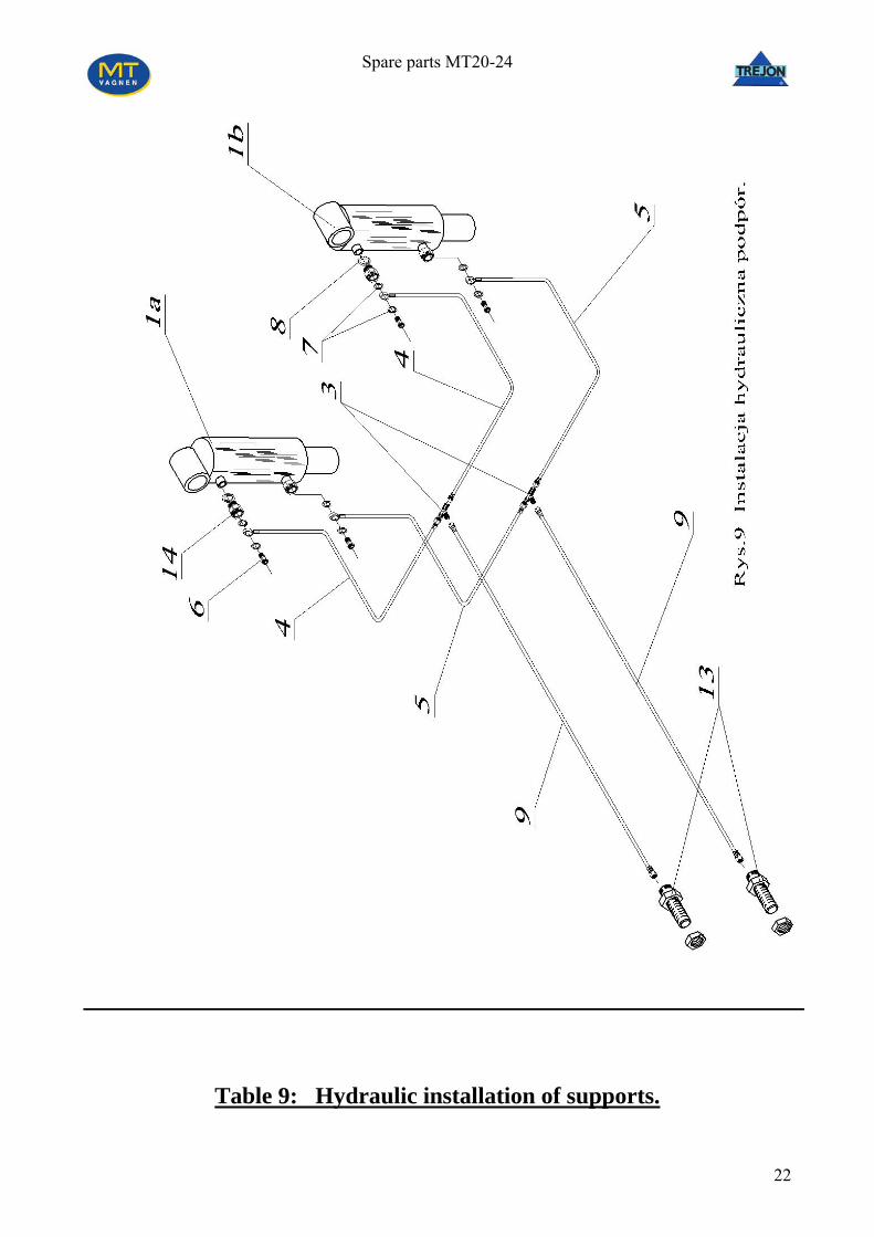
Table 9: Hydraulic installation of supports.
22
Spare parts MT20-24
o Name of parts Catalogue number Quantity Code N1a Cylinder of right rocker PH16/09.001 1 3232 1b. Cylinder of left rocker PH16/09.002 1 3232 2. 3. Symmetrical connecter M18 PN-66/M-73147 2 448 4. Hydraulic line l=800 P 1 11P01-10-2/M18x1,5 l-800 2 8546
5. Hydarulic line l=1100 P11P01-10-2/M18x1,5 l-1100 2 18596 6. Special screw M18x1,5 PH16/09.007 4 4621 7. Copper basket Ø18 8 1683 8. Copper gasket Ø20 4 1684 9. Hydraulic line l=5500 P12P11-10 1,5 l-5500 -2/M18x 2 18840 10. 11. 12. 13. Straight connection X SV NW 10HL 2 22259 14. Connecter from ½ on M18x1,5 H24.05.065.0.Z 4 22497
23
Spare parts MT20-24
24
Spare parts MT20-24
Table 10a: Hydraulic installation of advance of arm.
Table 10b: Hydraulic installation of advance arm with hydraulic blocking of container.
o Name of parts Catalogue number Quantity Code N1. Cylinder PH16/10.001 1 297 2. Straight connecter XVMNV 10HL 18ED 2 2 22603. Straight connection X SV NW 10HL 2 22259 4. Complete valve H24.05.031 1 20109 5. Knee connection XVEW NW 13HL 2 20141 6. Hydraulic line l=10100 P12P12-10-2/M18x1,5 l-10100-
90° 1 18839
7. Hydraulic line l=2750 P12P12-10-2/M18x1,5 l-2750-180° 1 20143
8. Hydraulic line l=8250 P12P12-10-2/M18x1,5 l-8250-180° 1 20142
27
Spare parts MT20-24
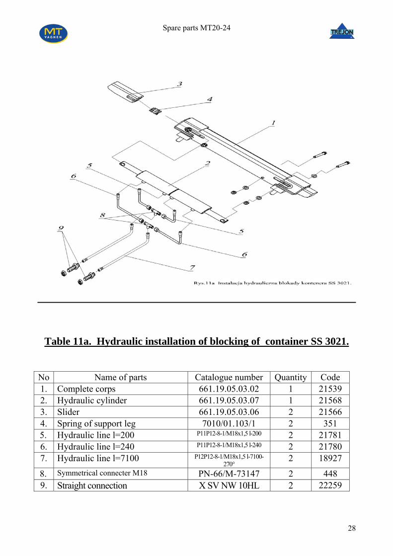
Table 11a. Hydraulic installation of blocking of container SS 3021.
No Name of parts Catalogue number Quantity Code 1. Complete corps 661.19.05.03.02 1 21539 2. Hydraulic cylinder 661.19.05.03.07 1 21568 3. Slider 661.19.05.03.06 2 21566 4. Spring of support leg 7010/01.103/1 2 351
5. Hydraulic line l=200 P11P12-8-1/M18x1,5 l-200 2 21781 6. Hydraulic line l=240 P11P12-8-1/M18x1,5 l-240 2 21780 7. Hydraulic line l=7100 P12P12-8-1/M18x1,5 l-7100-
Table 13. Hydraulic installation of steering axle.
No Name of parts Catalogue number Quantity Code 1. Straight connecter XVRNW 10HL ED 2 3064 2. Symmetrical connecter M18 PN-66/M-73147 2 448 3. Straight connection X SV NW 10HL 2 22259 4. Hydraulic line l=1350 P11P11-10-2/M18x1,5 l-1350 2 20912
5. Hydraulic line l=5500 P12P11-10-2/M18x1,5 l-5500 2 18840
Spare parts MT20-24
32
Spare parts MT20-24
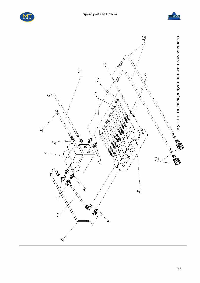
Table 14: Hydraulic installation of distributor.
No Name of parts Catalogue number Quantity Code 1. Valvular block NG10 DS5-S1/10N-
11. Hydraulic line l=2200 P11P12-16-2/M26x1,5 l-2200 2 20049 12. Hydraulic line l=850 P11P11-10-2/M18x1,5 l-850 10 18854 13. Hydraulic line l=500 P11P11-10-2/M18x1,5 l-500 2 18802 14. Quick coupler
wg ISO 7241-1:1987 (PN-92/M-73182/01)
M26x1,5 2 11628
15. Hydraulic pipe Ø18x2 0,15 20955
33
Spare parts MT20-24
34
Spare parts MT20-24
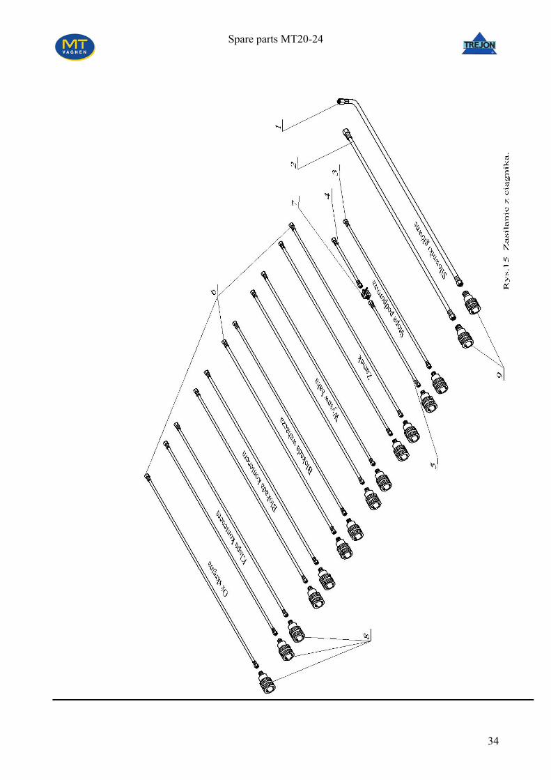
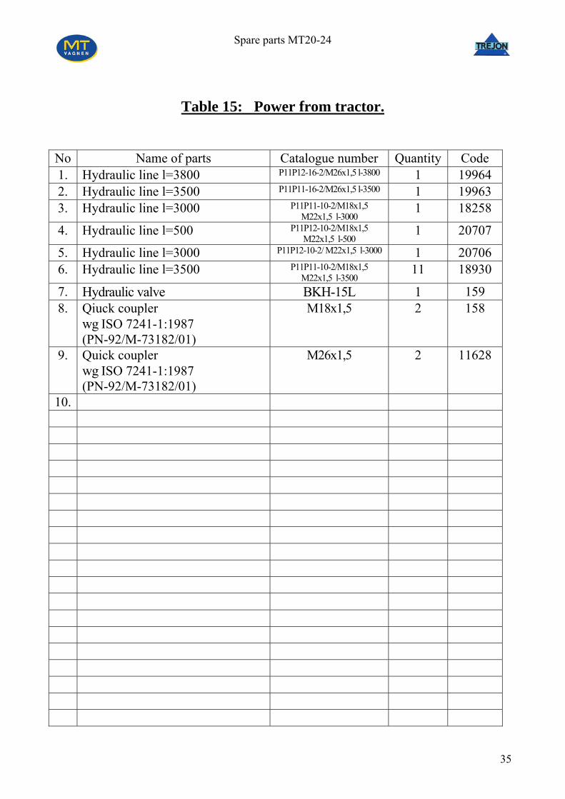
Table 15: Power from tractor.
No Name of parts Catalogue number Quantity Code 1. Hydraulic line l=3800 P11P12-16-2/M26x1,5 l-3800 1 19964 2. Hydraulic line l=3500 P11P11-16-2/M26x1,5 l-3500 1 19963 3. Hydraulic line l=3000 P11P11-10-2/M18x1,5
M22x1,5 l-3000 1 18258
4. Hydraulic line l=500 P11P12-10-2/M18x1,5 M22x1,5 l-500
1 20707
5. Hydraulic line l=3000 P11P12-10-2/ M22x1,5 l-3000 1 20706 6. Hydraulic line l=3500 P11P11-10-2/M18x1,5
M22x1,5 l-3500 11 18930
7. Hydraulic valve BKH-15L 1 159 8. Qiuck coupler
wg ISO 7241-1:1987 (PN-92/M-73182/01)
M18x1,5 2 158
9. Quick coupler wg ISO 7241-1:1987 (PN-92/M-73182/01)
M26x1,5 2 11628
10.
35
Spare parts MT20-24
36
Spare parts MT20-24
Table 16. Electric installation
No Name of parts Catalogue number Quantity Code 1 Back right lamp E549P 1 775 2 Back left lamp E549L 1 774 3 Orange reflection rectangle 8 872 4 Number plate illumination lamp 2 772 5 Electric box IP-42 1 9259 6 Electric box cover - 1 9259 7 Red-white back contour lamp - 2 771 8 Side lamp – white colour - 2 773 9 White front contour lamp - 2 863 10 Reflection triangle - 2 862 11 Outstanding triangle - 1 3352 12 13 Bracket of side lamp 661.19.05.04 2 21714 14 Left bracket of front lamp PH10/10.003 1 6340 15 Right bracket of front lamp PH10/10.004 1 6343 16 Bolt of bracket PH16/01.017 1 3357 17 Plug for connection on the traktor
with 7 electrical points - 2 1794
18 Electric line 6x1x1,5 - 1 858 19 Electric line 2x1 - 8 844 20 Electric line 4x1 - 2 850 21 Electric line 2x1 - 2 844
37
Spare parts MT20-24
38
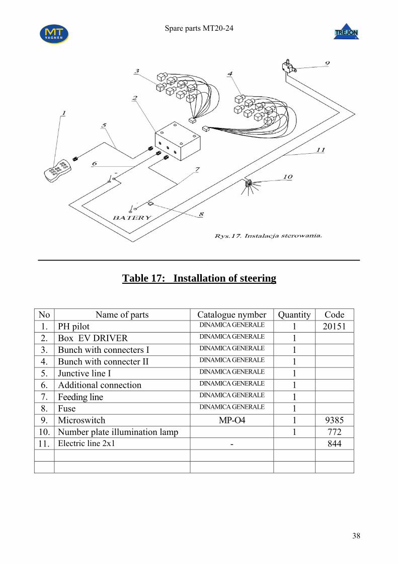
Table 17: Installation of steering
No Name of parts Catalogue nymber Quantity Code 1. PH pilot DINAMICA GENERALE 1 20151 2. Box EV DRIVER DINAMICA GENERALE 1 3. Bunch with connecters I DINAMICA GENERALE 1 4. Bunch with connecter II DINAMICA GENERALE 1 5. Junctive line I DINAMICA GENERALE 1 6. Additional connection DINAMICA GENERALE 1 7. Feeding line DINAMICA GENERALE 1 8. Fuse DINAMICA GENERALE 1 9. Microswitch MP-O4 1 9385 10. Number plate illumination lamp 1 772 11. Electric line 2x1 - 844
Spare parts MT20-24
39
Table 18: Complete axle. No Name of parts Catalogue number Quantity Code 1 Complete axle PH19/13.003 1 20277
2 Tire 550/60 X 22,5 4 19910 3 Wheel band 16,00x22,5 4 19910 4 Expander PH19/14.001 2 5 Lever of expander PH19/14.002 2 6 Distance washer PH19/14.003 2 7 Back conic bearing PH19/14.004 2 8 Front conic bearing PH19/14.005 2 9 Jaw with facing PH19/14.006 4 10 Spring PH19/14.007 4 11 Pin of wheel M22x1,5 PH19/14.008 20 12 Nut of pin of wheel M22x1,5 Fe/Zn 5 PH19/14.009 20 13 Washer PH19/14.010 2 14 Castellated nut PH19/14.011 2 15 Cotter PH19/14.012 2 16 Calpack PH19/14.013 2
Spare parts MT20-24
40
Spare parts MT20-24
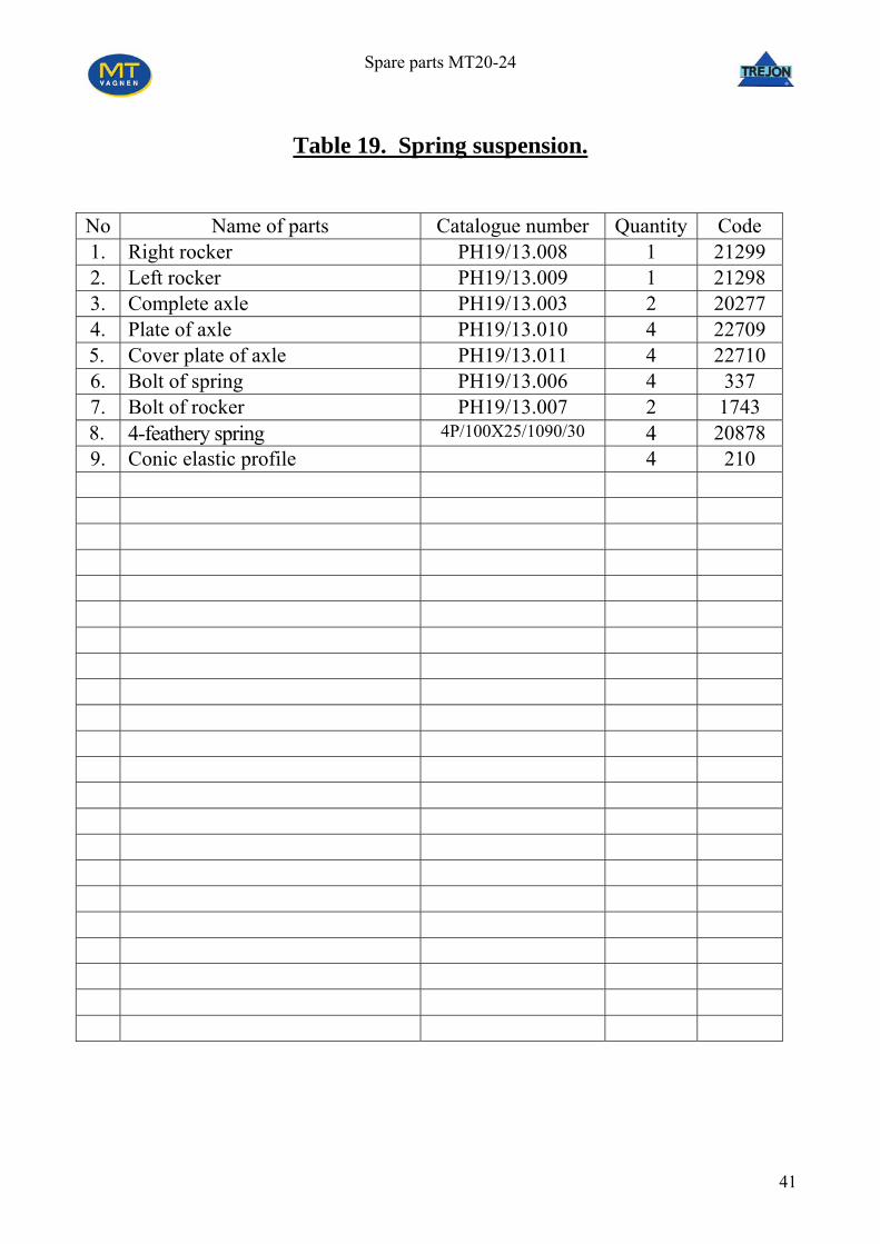
Table 19. Spring suspension.
No Name of parts Catalogue number Quantity Code 1. Right rocker PH19/13.008 1 21299 2. Left rocker PH19/13.009 1 21298 3. Complete axle PH19/13.003 2 20277 4. Plate of axle PH19/13.010 4 22709
5. Cover plate of axle PH19/13.011 4 22710 6. Bolt of spring PH19/13.006 4 337 7. Bolt of rocker PH19/13.007 2 1743