38
Boolean Logic CS.352.F12

Boolean LogicCS.352.F12

Boolean Algebra
Boolean Algebra
Mathematical system used tomanipulate logic equations.
● Boolean: deals with binary values(True/False, yes/no, on/off, 1/0)
● Algebra: set of operations to manipulate values and evaluate expressions
Boolean Functions
A Boolean function is a function that operates on binary inputs and returns binary outputs.
● Play a central role in the specification, construction, and optimization of hardware architectures.
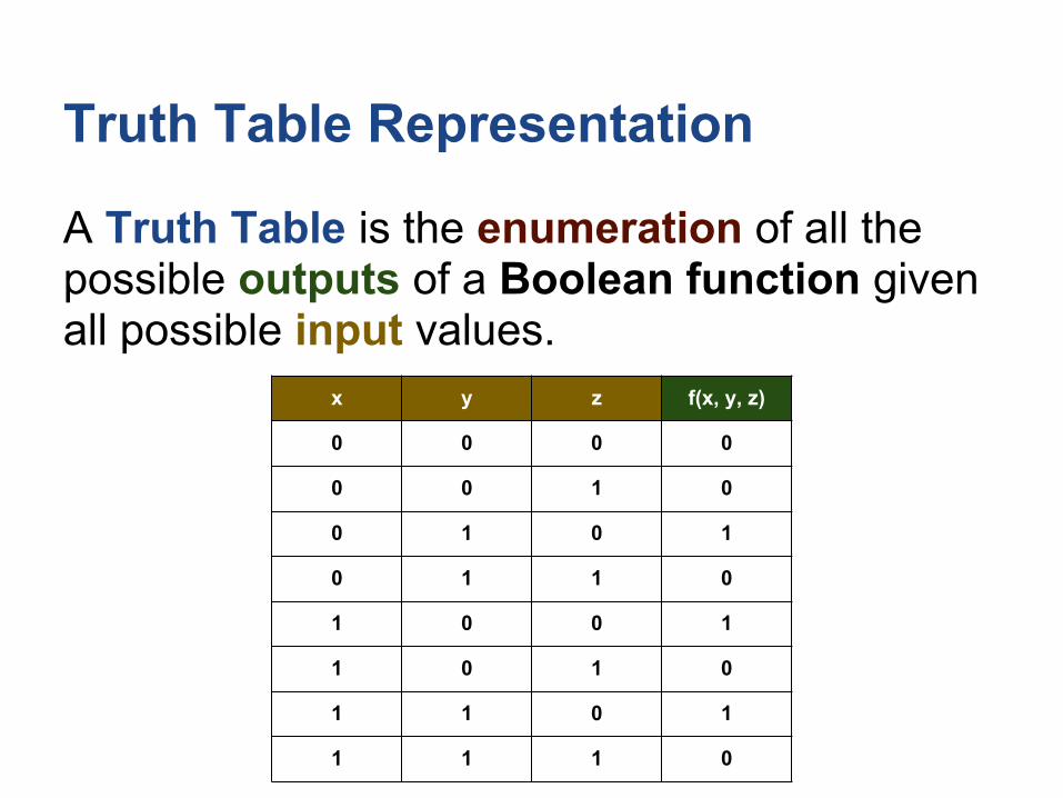
Truth Table Representation
A Truth Table is the enumeration of all the possible outputs of a Boolean function given all possible input values.
x y z f(x, y, z)
0 0 0 0
0 0 1 0
0 1 0 1
0 1 1 0
1 0 0 1
1 0 1 0
1 1 0 1
1 1 1 0
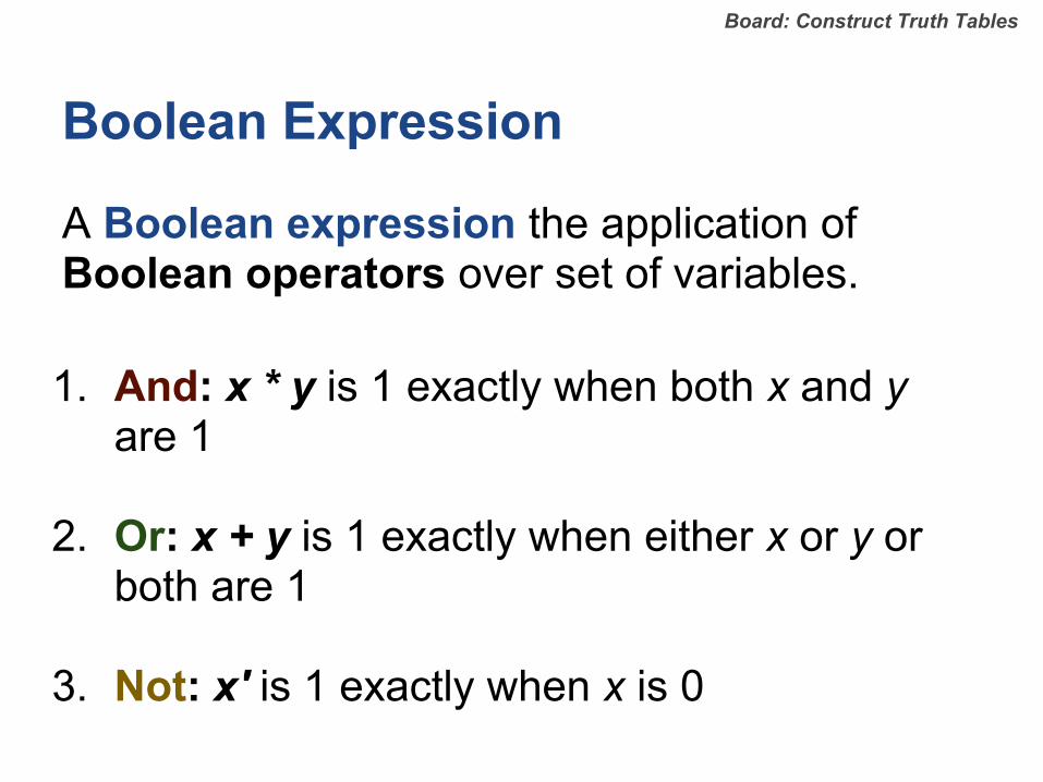
Boolean Expression
A Boolean expression the application of Boolean operators over set of variables.
1. And: x * y is 1 exactly when both x and y are 1
2. Or: x + y is 1 exactly when either x or y or both are 1
3. Not: x' is 1 exactly when x is 0
Board: Construct Truth Tables

Exercise 1: Boolean Expression -> Truth Tables
Construct truth tables for the following boolean expressions:
1. f(x, y) = x' + y
2. f(x, y, z) = (x * y) + (y * z')

Exercise 1: Boolean Expression -> Truth Tables
1. f(x, y) = x' + y
x y f(x, y)
0 0 1
0 1 1
1 0 0
1 1 1
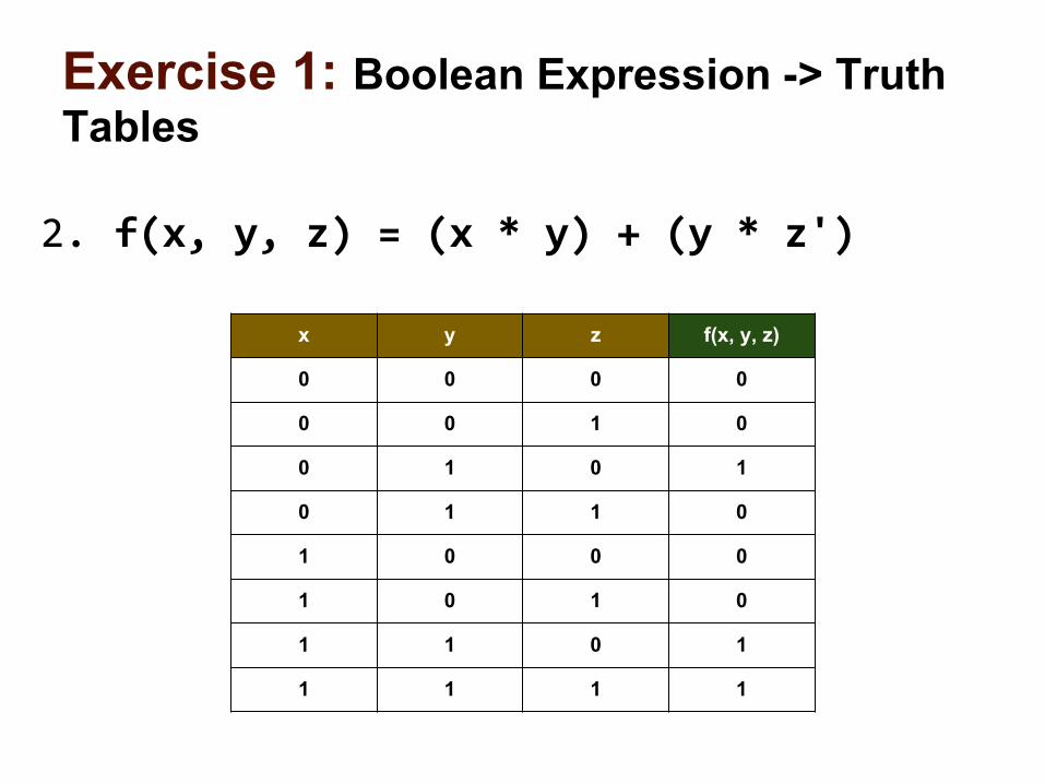
Exercise 1: Boolean Expression -> Truth Tables
2. f(x, y, z) = (x * y) + (y * z')
x y z f(x, y, z)
0 0 0 0
0 0 1 0
0 1 0 1
0 1 1 0
1 0 0 0
1 0 1 0
1 1 0 1
1 1 1 1

Canonical Representation
Every Boolean function can be expressed using at least one Boolean expression called the canonical representation:
For each row in truth table where output is 1, construct a term by And-ing together the variables of that row, and then Or all of these terms to form a Sum of Products.
Every Boolean function, no matter how complex, can be expressed using three Boolean operators only: And,
Or, and Not.
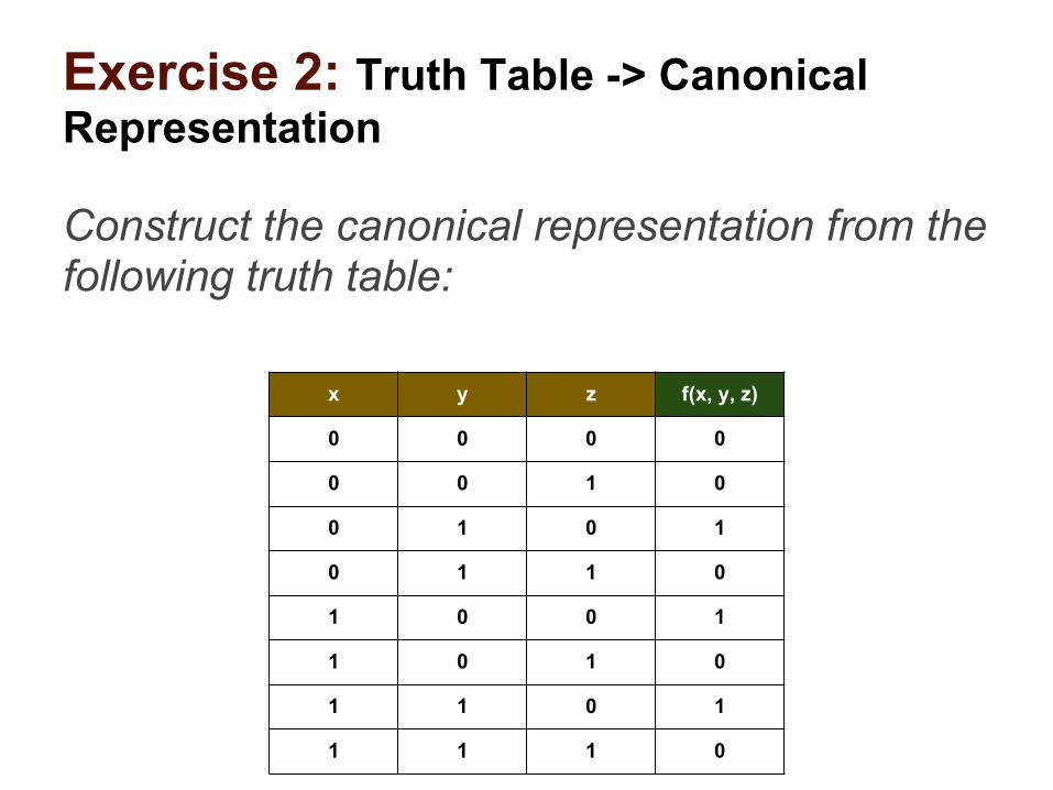
Exercise 2: Truth Table -> Canonical Representation
Construct the canonical representation from the following truth table:
x y z f(x, y, z)
0 0 0 0
0 0 1 0
0 1 0 1
0 1 1 0
1 0 0 1
1 0 1 0
1 1 0 1
1 1 1 0

Exercise 2: Truth Table -> Canonical Representation
f(x, y, z) = x'yz' + xy'z' + xyz'
x y z f(x, y, z)
0 0 0 0
0 0 1 0
0 1 0 1
0 1 1 0
1 0 0 1
1 0 1 0
1 1 0 1
1 1 1 0

Minimization
While there is only one truth table representation for every Boolean function, there may exist multiple boolean expressions.
For economic reasons, we usually want to minimize or reduce the number of logical operators used in our boolean expression.

Minimization: Algebraic Laws
Identity A * 1 = A
A + 0 = A
Annulment A + 1 = 1
A * 0 = 0
Complement A + A' = 1
A * A' = 0
Indempotent A + A = A
A * A = A

Minimization: More Algebraic Laws
Associative Law A * B * C = (A * B) * C = A * (B * C)
A + B + C = (A + B) + C = A + (B + C)
Commutative Law A * B * C = B * A * C = ...
A + B + C = B + A + C = ...
Distributive Law A * (B + C) = (A * B) + (A * C)
A + (B * C) = (A + B) * (A + C)
DeMorgan's Law (A * B)' = A' + B'
(A + B)' = A' * B'

Exercise 3: Minimize with Algebraic Laws
Simplify the following Boolean function:
f(x, y, z) = x'yz' + xy'z' + xyz'

Exercise 3: Minimize with Algebraic Laws
f(x, y, z) = x'yz' + xy'z' + xyz'
factor = z'(x'y + xy' + xy)
factor = z'(x'y + x(y' + y))
complement = z'(x'y + x(1))
identity = z'(x'y + x)
distribute = z'((x' + x) * (y + x))
complement = z'((1) * (y + x))
identity = z'(y + x)

Minimization: Karnaugh Maps
Logic graph where all logic domains are continuous, making logic relationships easy to identify.
Board: Simplify Expression
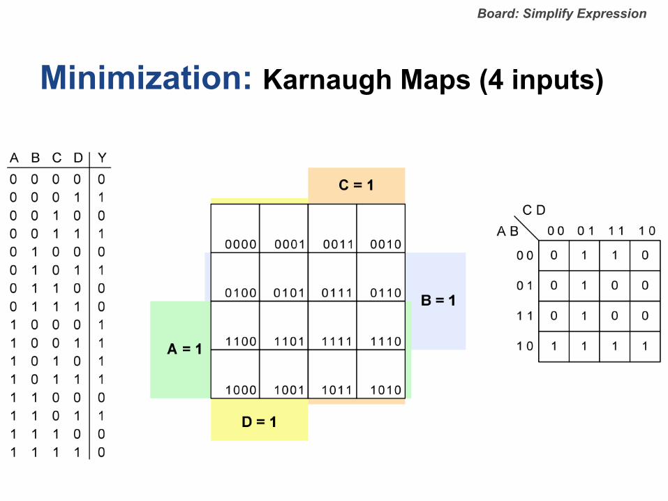
Minimization: Karnaugh Maps (4 inputs)
Board: Simplify Expression
Logic Gate
Logic Gate
A gate is a physical device that implements a Boolean function.
- Inputs and outputs of a Boolean Function = Input and output pins of gate.
- Today, most gates are implemented as transistors etched in silicon (chips).
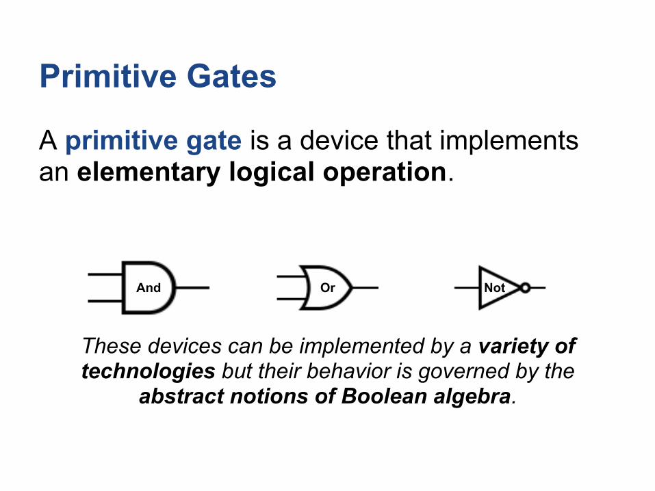
Primitive Gates
A primitive gate is a device that implements an elementary logical operation.
These devices can be implemented by a variety of technologies but their behavior is governed by the
abstract notions of Boolean algebra.
And Or Not
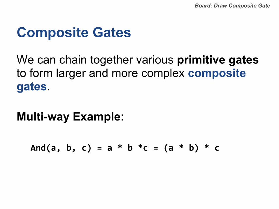
Composite Gates
We can chain together various primitive gates to form larger and more complex composite gates.
Multi-way Example:
And(a, b, c) = a * b *c = (a * b) * c
Board: Draw Composite Gate

Exercise 4: boolean function -> gates
Implement the following boolean functions as composite gates:
1. Nand(a, b) = (a*b)'
2. Xor(a, b) = a*b' + a'*b
3. And(a, b, c, d) = a*b*c*d

Exercise 4: boolean function -> gates
Draw composite gates on the board.

Interface vs Implementation
Each logic gate has a unique interface, but may have multiple implementations.
Interface: the input and output pins exposed to the outside world and the specified behavior.
Implementation: the manner in which the specified behavior is accomplished.
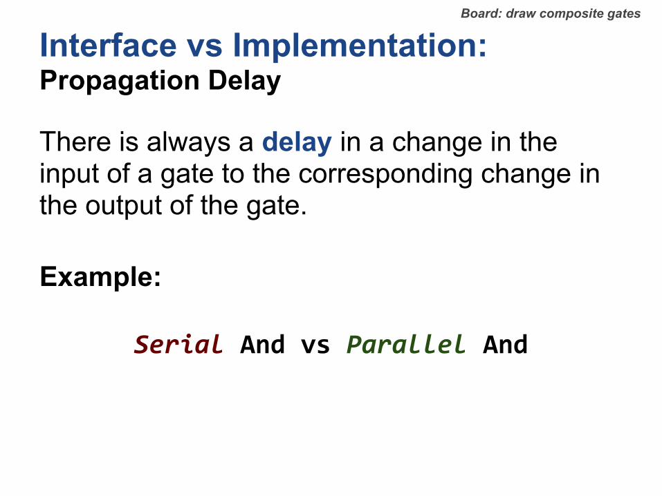
Interface vs Implementation: Propagation Delay
There is always a delay in a change in the input of a gate to the corresponding change in the output of the gate.
Example:
Serial And vs Parallel And
Board: draw composite gates

Multiplexers
A multiplexer is a three-input gate that uses one of the inputs, called the "selection bit", to select and output one of the other two inputs, called "data bits".
Board: Write Truth table & Boolean Expression
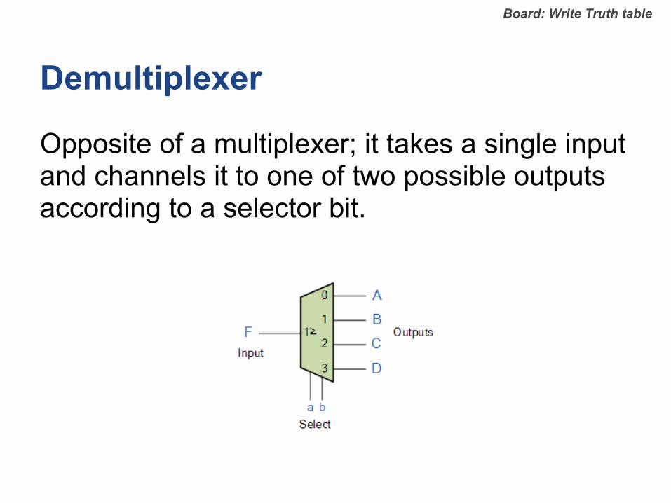
Demultiplexer
Opposite of a multiplexer; it takes a single input and channels it to one of two possible outputs according to a selector bit.
Board: Write Truth table
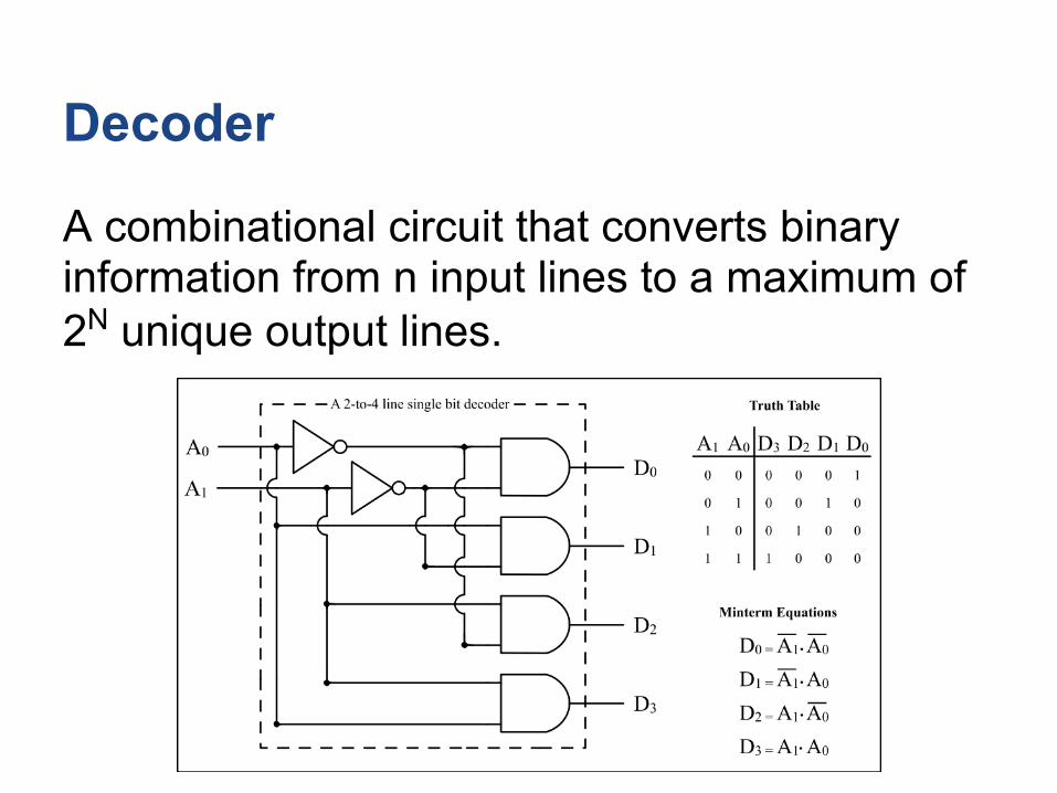
Decoder
A combinational circuit that converts binary information from n input lines to a maximum of 2N unique output lines.

Exercise 5: multiplexer
Implement a 4-to-1 multiplexor.

Exercise 5: multiplexer
1. Use 2-to-4 decoder and 4 And gates and an Or gate
2. Use 4 And3 gates and an Or gate
3. Use 3 2-to-1 multiplexers

Multi-bit Gates
Computer hardware normally operates on multi-bit arrays called buses.
Building a multi-bit gate is easy: construct arrays of n elementary gates.
Board: Sketch Multi-bit And

HDL

HDL
Today's hardware designers use Hardware Description Languages to plan and optimize their chip architectures.
- Simulate the hardware.
- Test the hardware.
- Model resource usage.
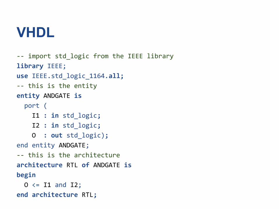
VHDL-- import std_logic from the IEEE library
library IEEE;
use IEEE.std_logic_1164.all;
-- this is the entity
entity ANDGATE is
port (
I1 : in std_logic;
I2 : in std_logic;
O : out std_logic);
end entity ANDGATE;
-- this is the architecture
architecture RTL of ANDGATE is
begin
O <= I1 and I2;
end architecture RTL;
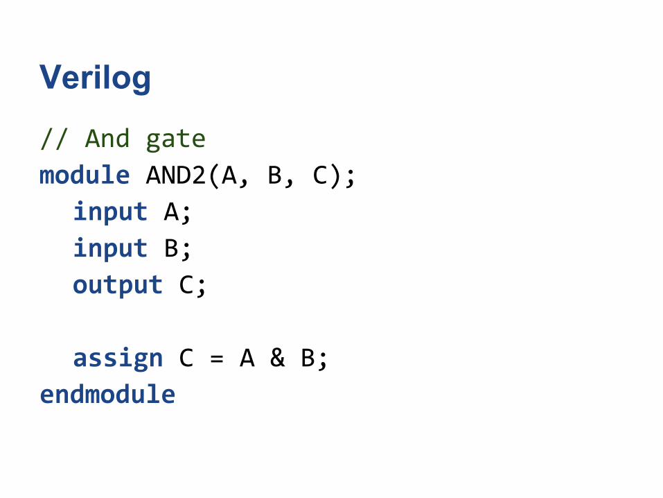
Verilog
// And gate
module AND2(A, B, C);
input A;
input B;
output C;
assign C = A & B;
endmodule


