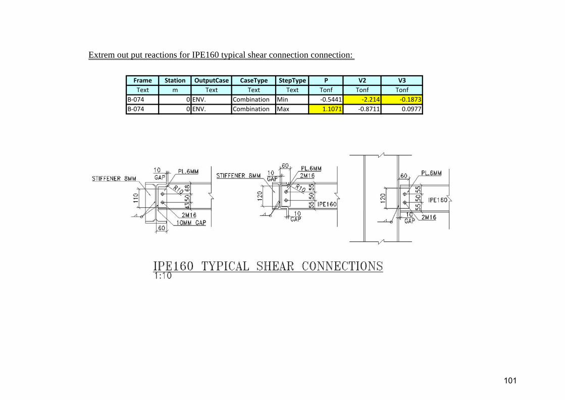
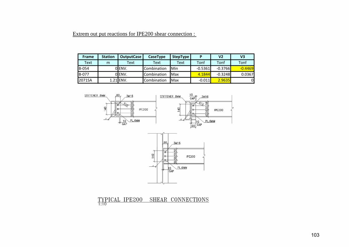
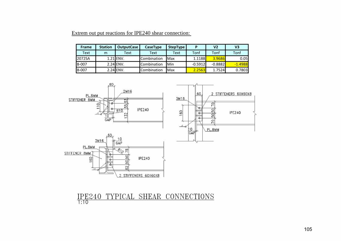
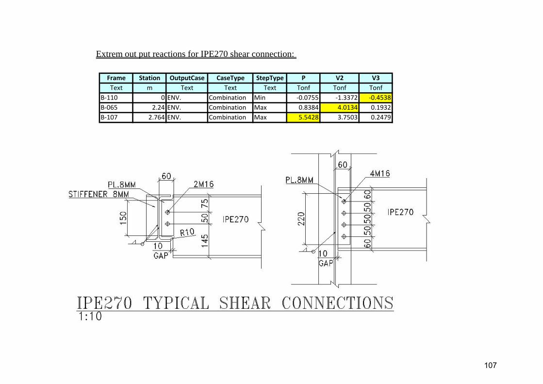
Page 1
ASEC for Manufacturing and Industrial Projects - ARESCO Tebbin Plant
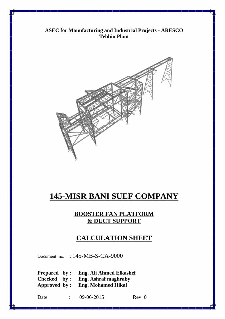
145-MISR BANI SUEF COMPANY
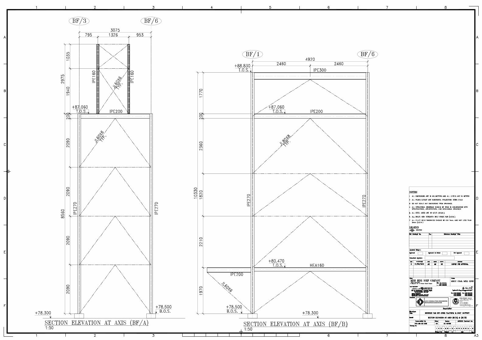
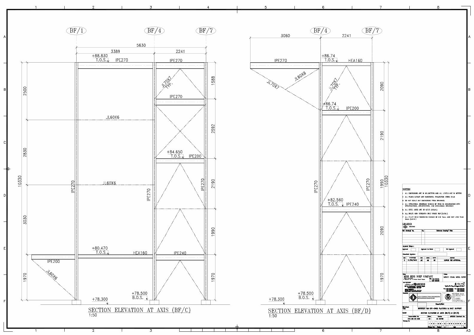
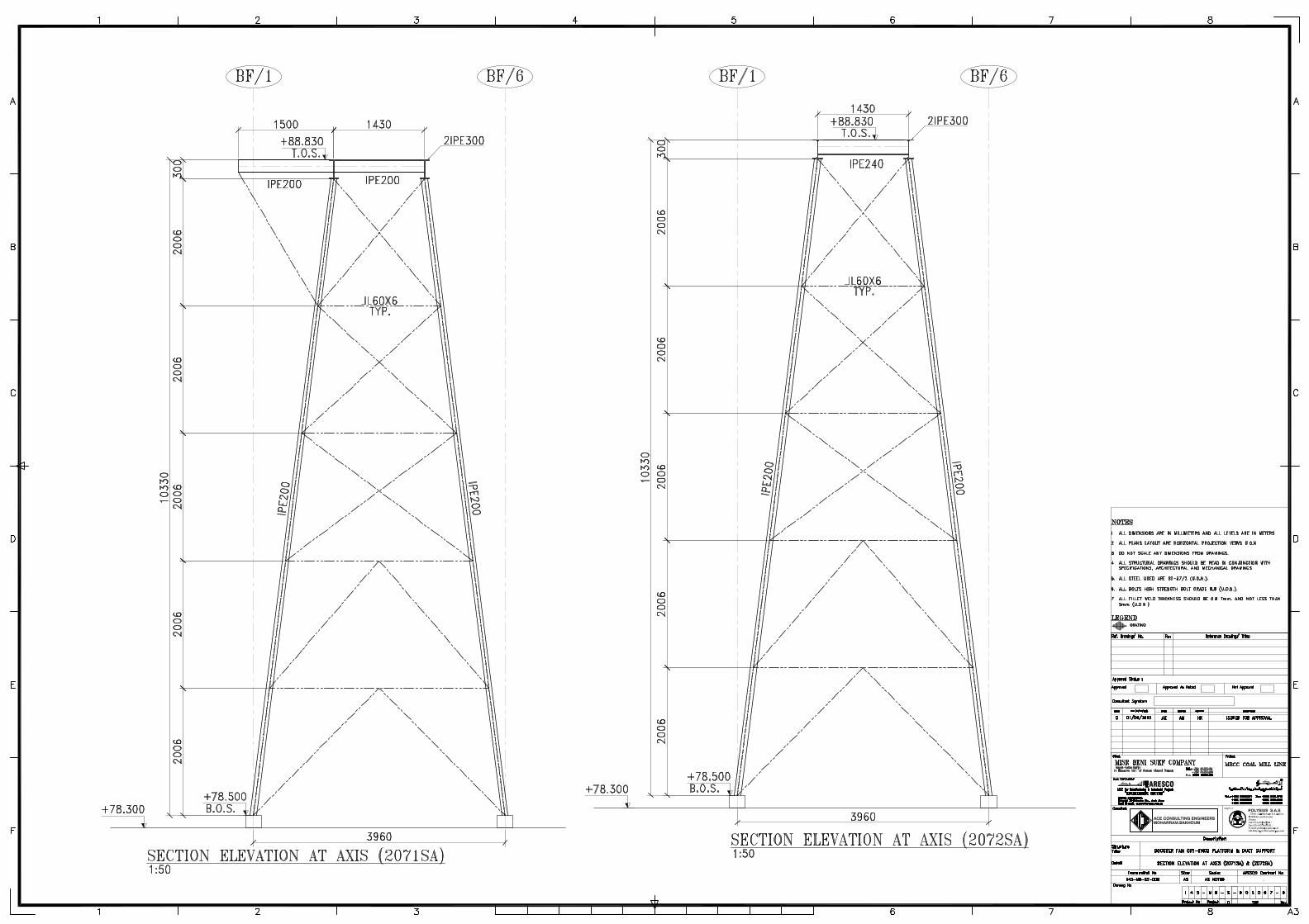
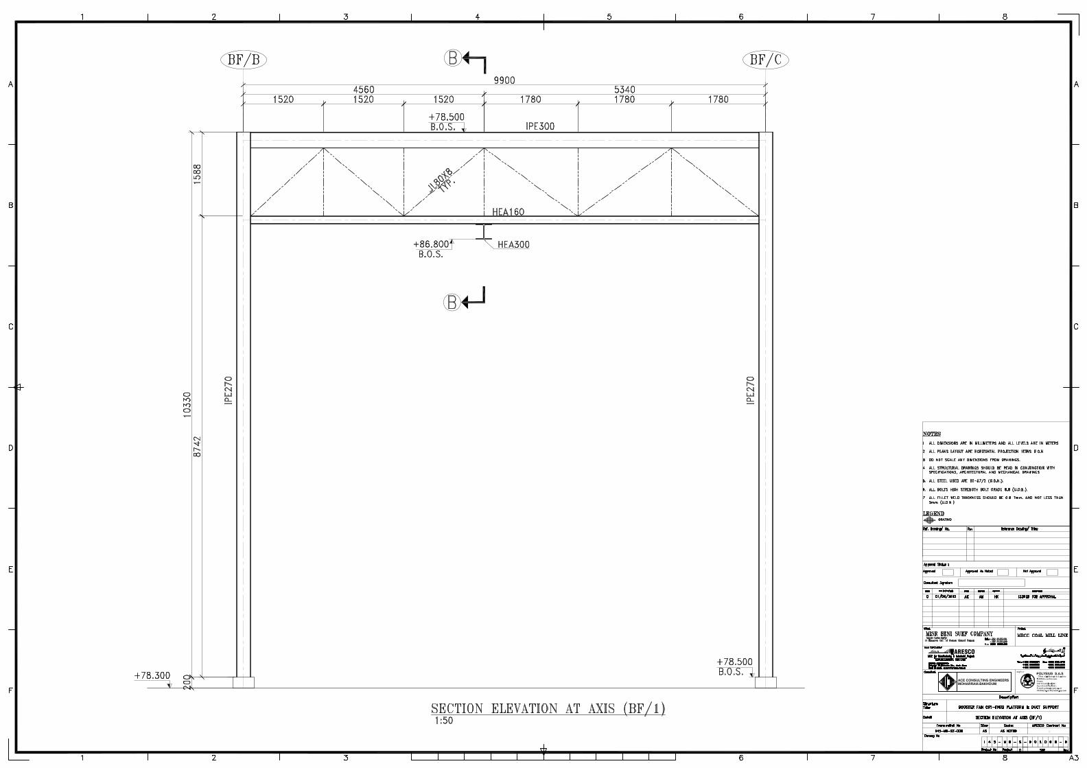
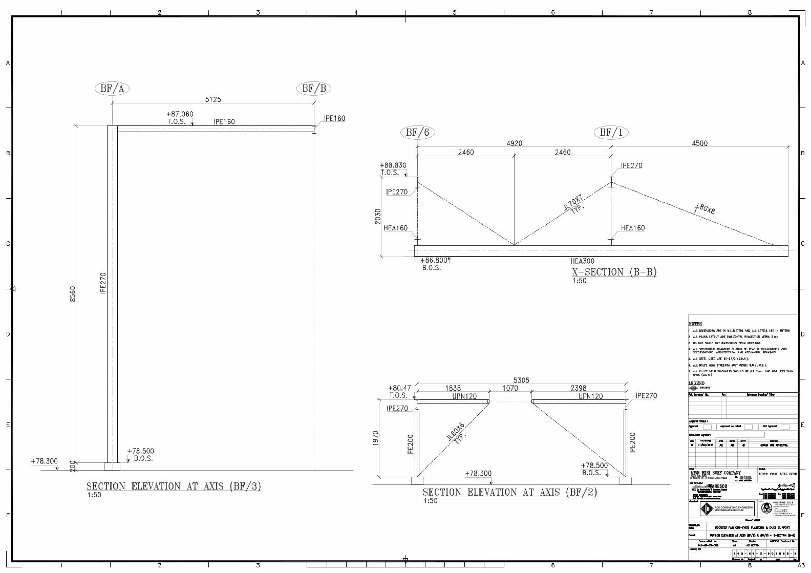
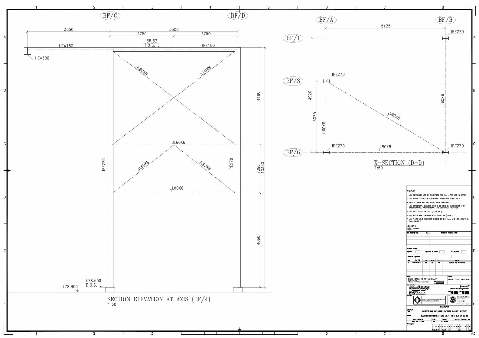
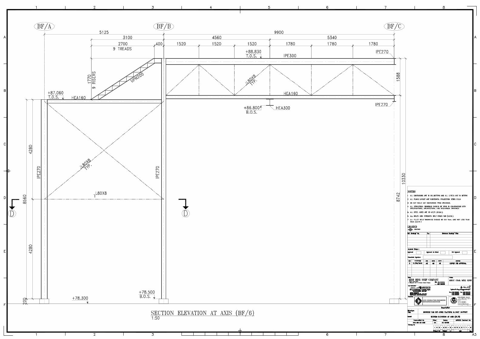
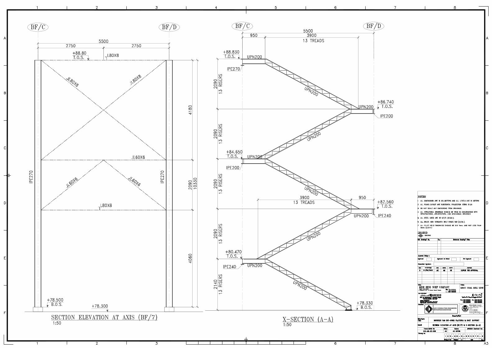
BOOSTER FAN PLATFORM
& DUCT SUPPORT
CALCULATION SHEET Document no. : 145-MB-S-CA-9000 Prepared by : Eng. Ali Ahmed Elkashef Checked by : Eng. Ashraf maghraby Approved by : Eng. Mohamed Hikal Date : 09-06-2015 Rev. 0
Page 2
1. INTRODUCTION 1
2. DESIGN DATA 2
2.1 Applicable codes and standards 22.2 Material Characteristics 22.3 Design Loads 32.4 Technical Specifications 4
3. ANALYSIS 15
3.1 Calculation Method 153.2 Main Assumptions 153.3 Model Configration 153.4 Load Combinations 56
4. DESIGN 60
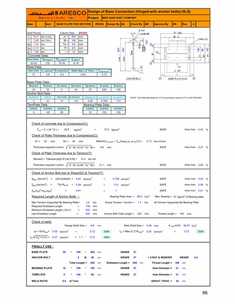
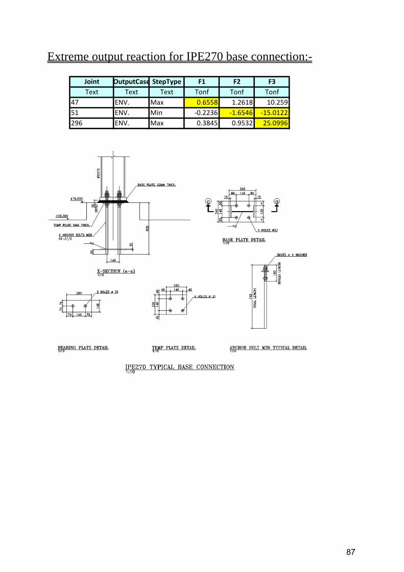
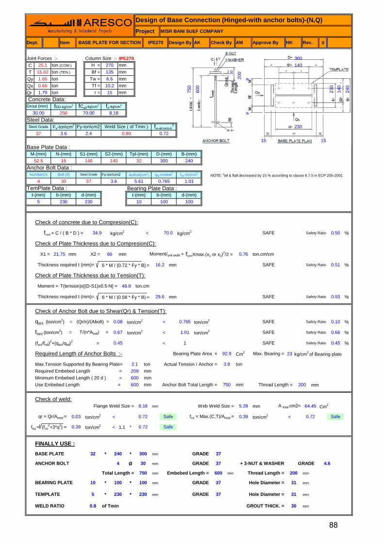
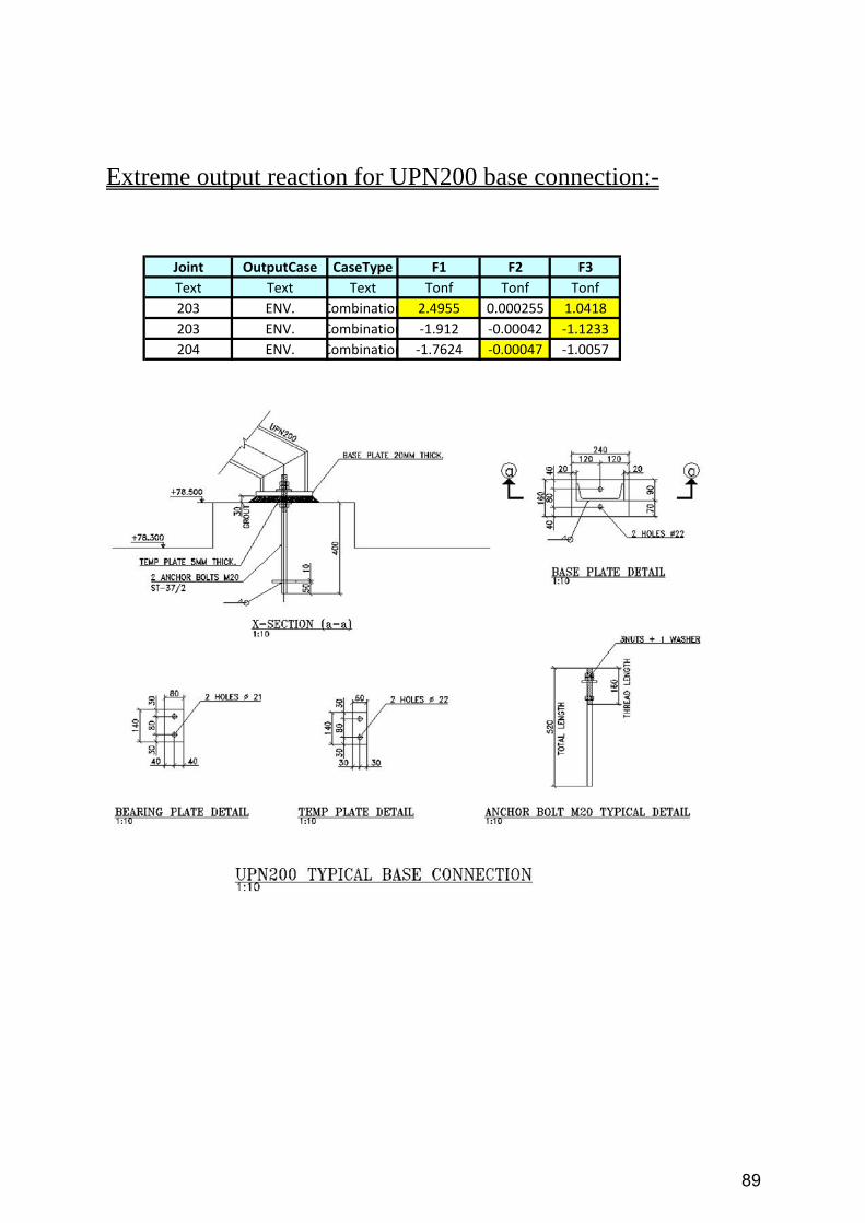
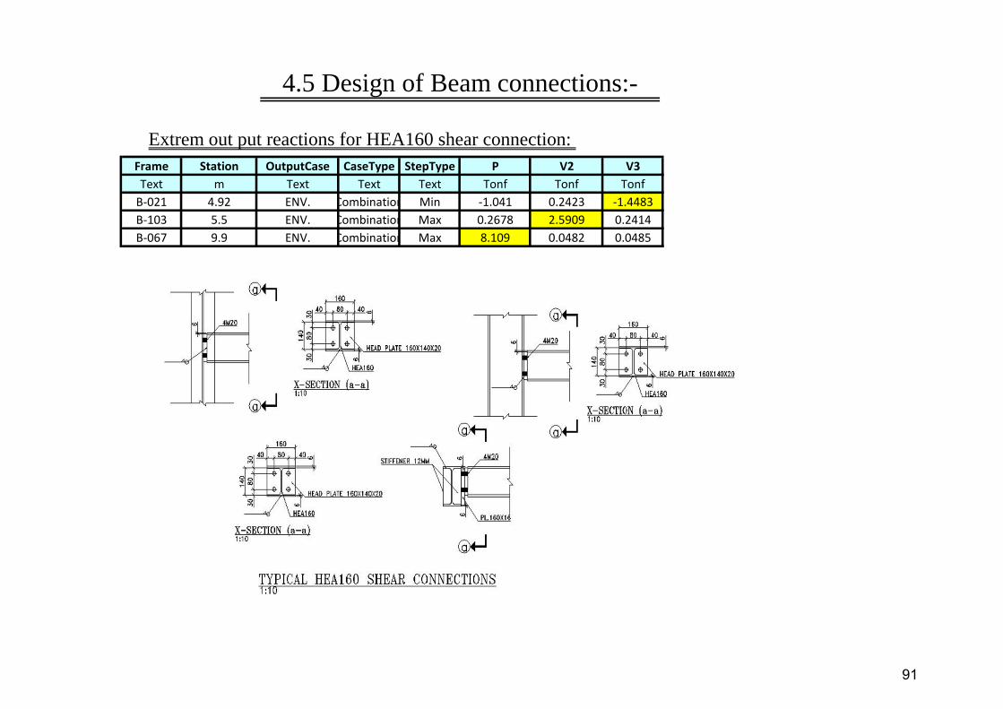
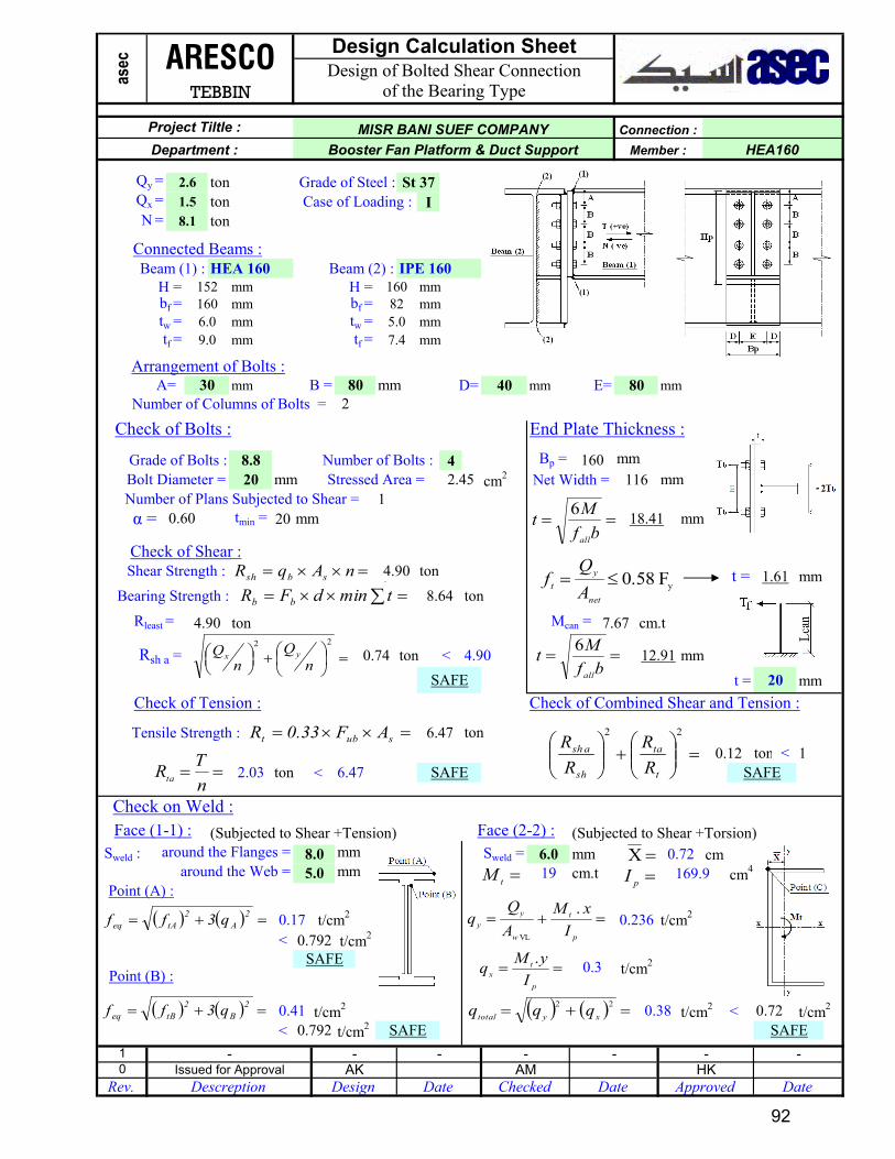
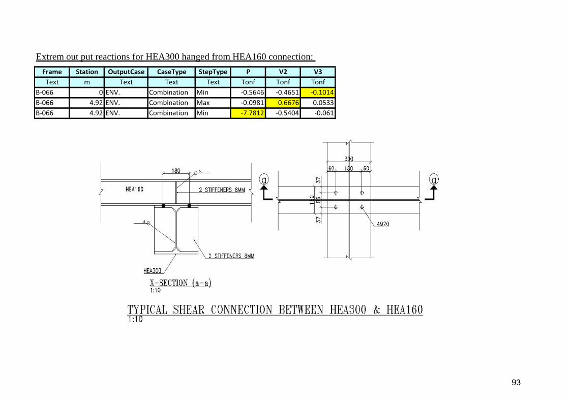
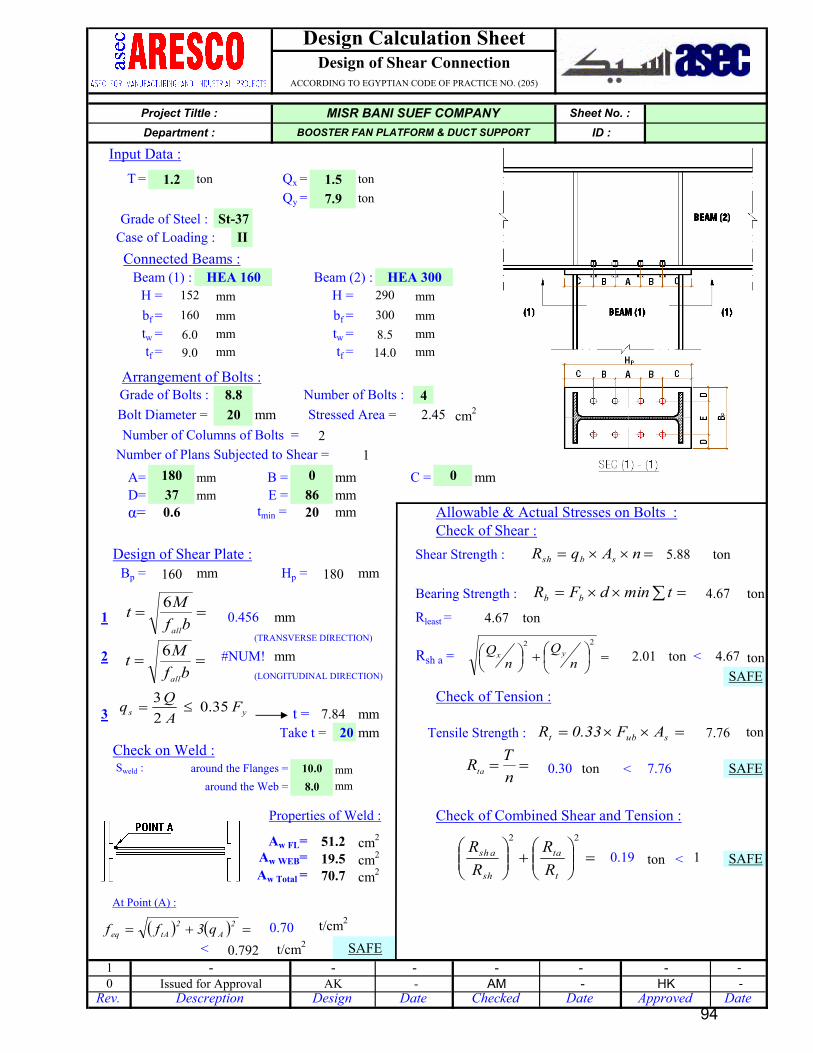
4.1 Allowable Stresses 604.2 Design of Beam Columns 614.3 Design of Bracing members 624.4 Design of Base connections 854.5 Design of Beam connections 91
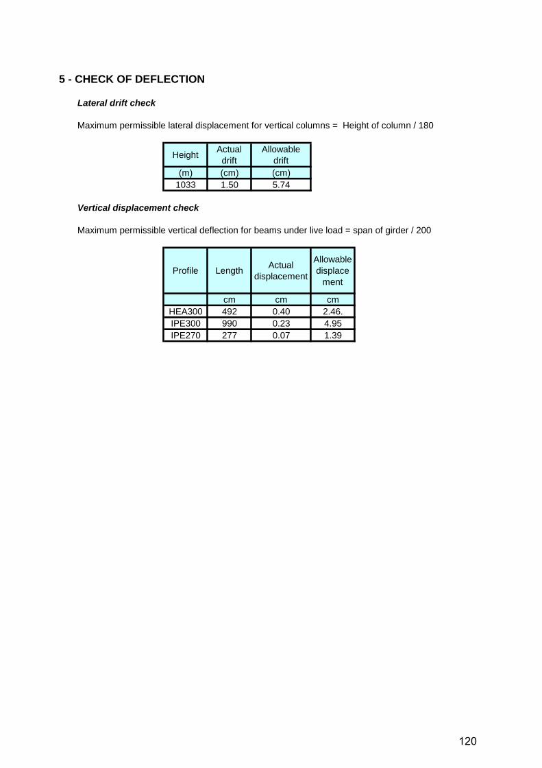
5 - CHECK OF DEFLECTION 120
APPENDIX (1) 121
INDEX
Page 3
1. INTRODUCTION
SAP 2000 V14.2.2
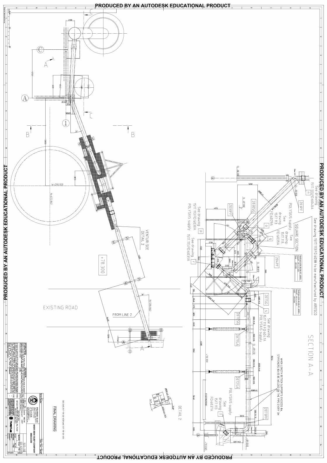
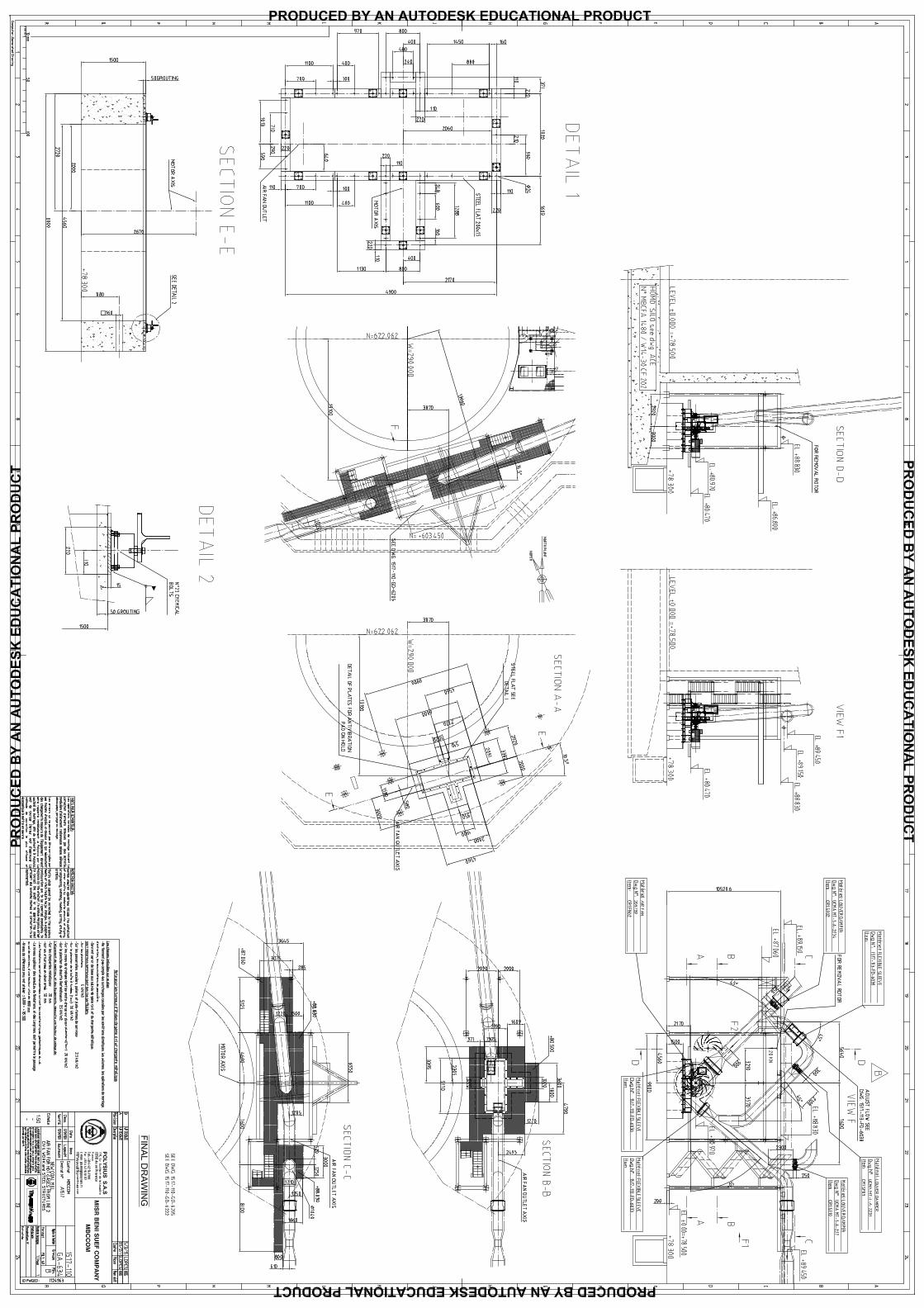
Reference Documents: (refer to Appendix (1)
Mechanical GAs drawings ---------------------------# 1517-110-GA-634B
Analysis has been carried out using the commercial software
This note is concerned with Fan CR1-FN02 platform Of Misr Bani Suef Company Project.
The aim of this document is to design the steel structure supporting the mechanical loads , and carry out all the necessary checks and verifications.
#1517-110-GD-6222#1517-110-GD-6224
1
Page 4
2. DESIGN DATA
2.1 Applicable codes and standards
- Structural steel design is in accordance with the Egyptian Code of Practice for Steel Constructions and Bridges (ASD) Code No. (205). Ministerial Decree No 279 - 2001 - Egyptian Code for Loads on Structural Elements and Buildings Code No. (201).
2.2 Material Characteristics
- Structural Steel :
Mass Density ( ) = 7.85 t/cm3
Modulus of Elasticity (E) = 2100 t/cm2
Coefficient of thermal Expansion () = 1.2x10⁻⁵ / oC
Structural Steel used is of Grade --- ST - 37Nominal ultimate strength ( Fu ) = 3.60 t/cm2 (Thickness < 40 mm)
= 3.40 t/cm2 (40 mm < Thickness < 100 mm)
Nominal yield strength ( Fy ) = 2.40 t/cm2 (Thickness < 40 mm)
= 2.15 t/cm2 (40 mm < Thickness < 100 mm)
- Bolts used are (HSB) High Strength bolts of the following grades:
Grade (8.8)Nominal ultimate strength ( Fub) = 8.00 t/cm2
Nominal yield strength ( Fyb) = 6.40 t/cm2
The bolt follows DIN 931 The nut follows DIN 555 The washer follows DIN 126
- Anchor bolts :
It is of steel grade ST - 37
Nominal ultimate strength ( Fu) = 3.60 t/cm2 (Diameters < 40 mm)
Nominal yield strength ( Fy) = 2.40 t/cm2 (Diameters < 40 mm)
- Welds :
The grade of weld material shall not be less than grade of base metal.
2
Page 5
2.3 Design Loads
(DL) Dead load
The dead loads include the self-weight of steel structure, and covering material.
The unit weight of steel = 7.85 t/m3
Grating plate (30x30x3) = 40 Kg/m2
(LL) Live load
This load applied in the areas with covering material and / or surrounding the machines.
- Live load on platf.(LL) = 250 Kg/m2
- Dust load on platf. = 50 Kg/m2
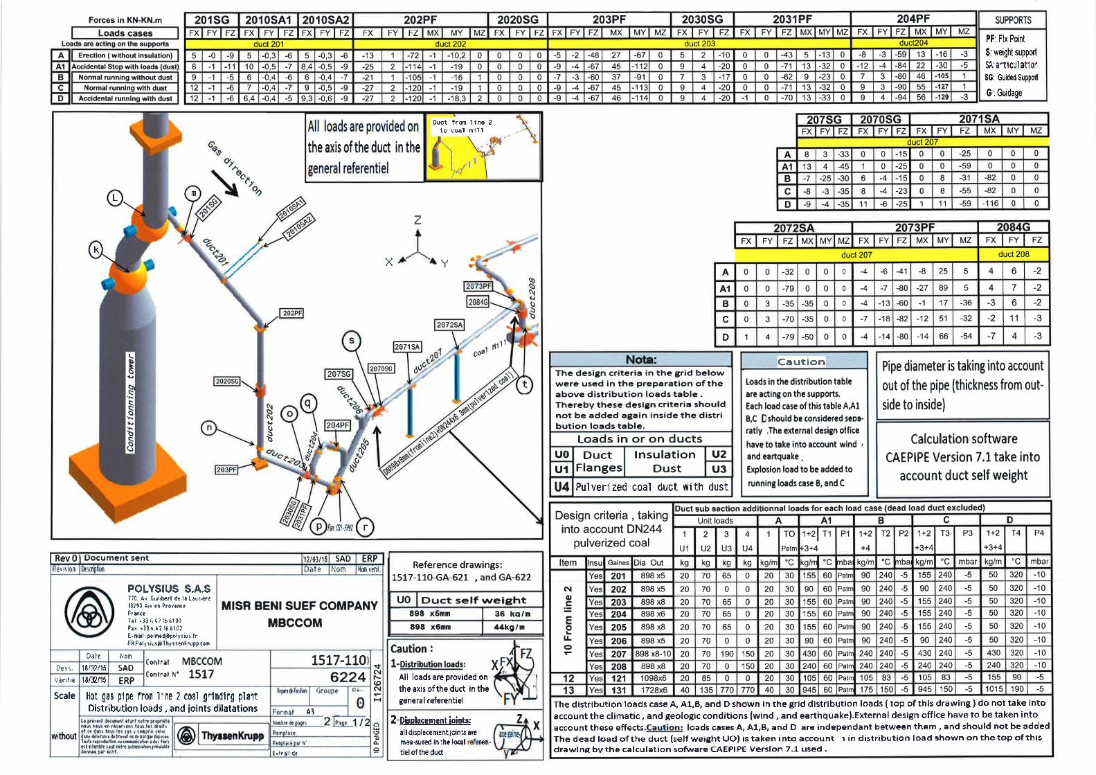
Mechanical loads
Refer to mechanical loads presented in 1517-110-GD-6224 (appendix (1))
(MD) Mechanical dead loads (permanent loads)
- MD ---- cosidered as Load case (A)
(ML) Mechanical live loads
- ML ---- cosidered as Load case (D) - Load case (A) except for support (207SG)
The basic design loads given here below include the most permanent or variable loads that should be considered in load combinations.
will be Load case (B) - Load case (A)
3
Page 6
(W) Wind loads
The design wind load (P) = Ce .k .q Where k is combined height, exposure factor.
Ce is pressure coefficient for the structure or portion of structure.
qs is wind pressure. qs = 0.078 T/m2
(Temp) Temperature load
(EQ) Seismic load
2.4 Technical Specifications
Deformations
Slenderness value for members
- Allowable slenderness ratio ( = K L / i ) should not increase than the following values:
For Tension Members: max < 300
For Compression Members:
For Beam Columns : max < 180
For Bracing Members : max < 200
Ce=1.3 for columns / 1.1 for beams
- The allowable vertical deflection due to live load for beams is limited to Span / 200 and for cantilevers is limited to Span/ 180
- The allowable lateral drift at top of columns due to combined lateral and gravity loads is limited to Height / 150 .
This load is taken in the longitudinal and transversal directions of structure in accordance with Egyptian Code (201).
The temperature effect will be considered by applying the change (increase or decrease) in
temperature = +30/-20 oC
For this type of light weight structures we can neglect its effect as it doesn't govern the design if compared with wind load.
4
Page 7
SAP2000
SAP2000 v14.2.2 - File:BFP - Frame Span Loads (DL) (As Defined) - Tonf, m, C Units
6/7/15 16:04:42
5
Page 8
SAP2000
SAP2000 v14.2.2 - File:BFP - Frame Span Loads (LL) (As Defined) - Tonf, m, C Units
6/7/15 16:05:29
6
Page 9
SAP2000
SAP2000 v14.2.2 - File:BFP - Frame Span Loads (MD) (As Defined) - Tonf, m, C Units
6/7/15 16:11:13
7
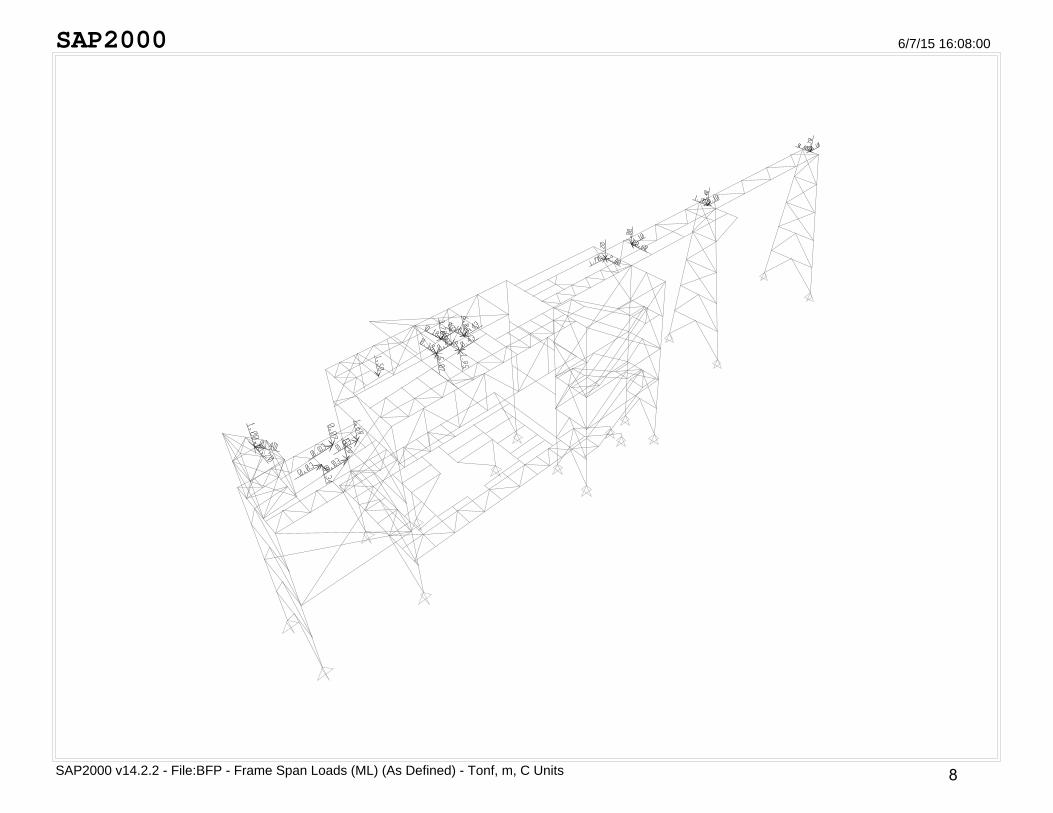
Page 10
SAP2000
SAP2000 v14.2.2 - File:BFP - Frame Span Loads (ML) (As Defined) - Tonf, m, C Units
6/7/15 16:08:00
8
Page 11
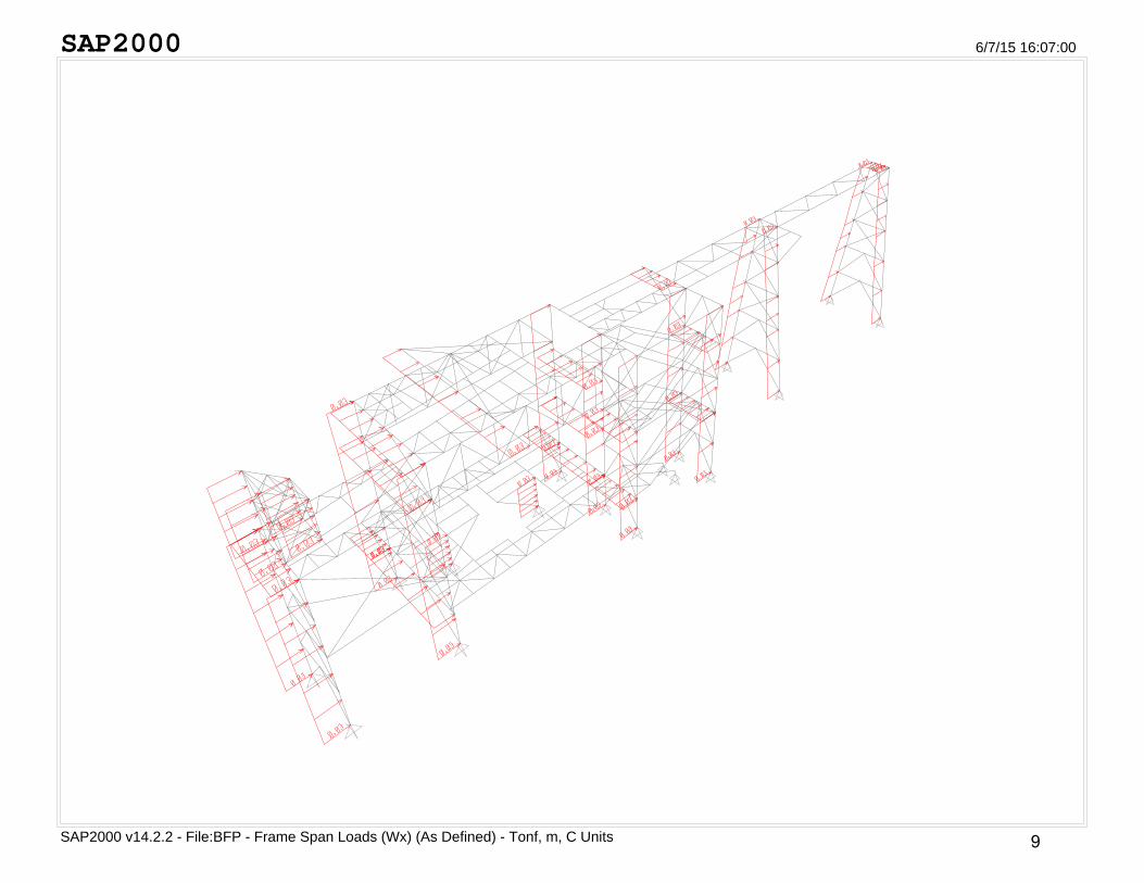
SAP2000
SAP2000 v14.2.2 - File:BFP - Frame Span Loads (Wx) (As Defined) - Tonf, m, C Units
6/7/15 16:07:00
9
Page 12
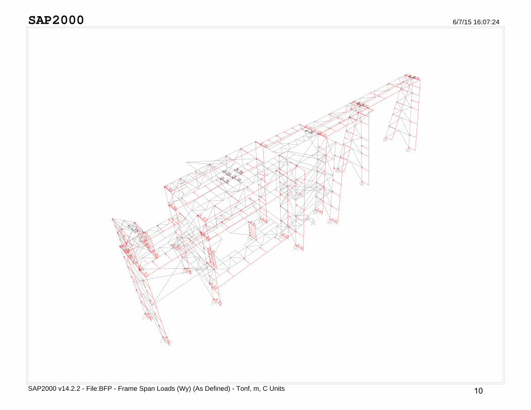
SAP2000
SAP2000 v14.2.2 - File:BFP - Frame Span Loads (Wy) (As Defined) - Tonf, m, C Units
6/7/15 16:07:24
10
Page 13
SAP2000
SAP2000 v14.2.2 - File:BFP - Frame Span Loads (C1) (As Defined) - Tonf, m, C Units
6/7/15 16:11:41
11
Page 14
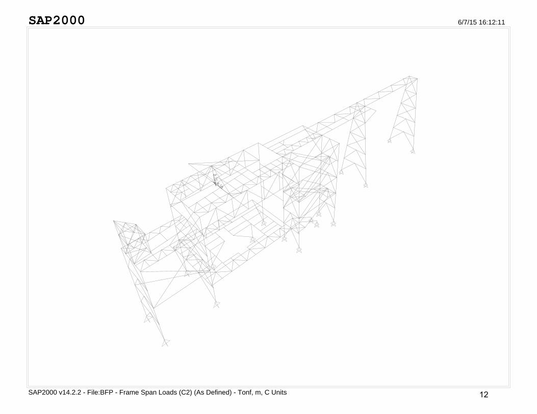
SAP2000
SAP2000 v14.2.2 - File:BFP - Frame Span Loads (C2) (As Defined) - Tonf, m, C Units
6/7/15 16:12:11
12
Page 15
SAP2000
SAP2000 v14.2.2 - File:BFP - Frame Span Loads (C3) (As Defined) - Tonf, m, C Units
6/7/15 16:12:52
13
Page 16
SAP2000
SAP2000 v14.2.2 - File:BFP - Frame Span Loads (C4) (As Defined) - Tonf, m, C Units
6/7/15 16:13:18
14
Page 17
3. ANALYSIS
3.1 Calculation Method
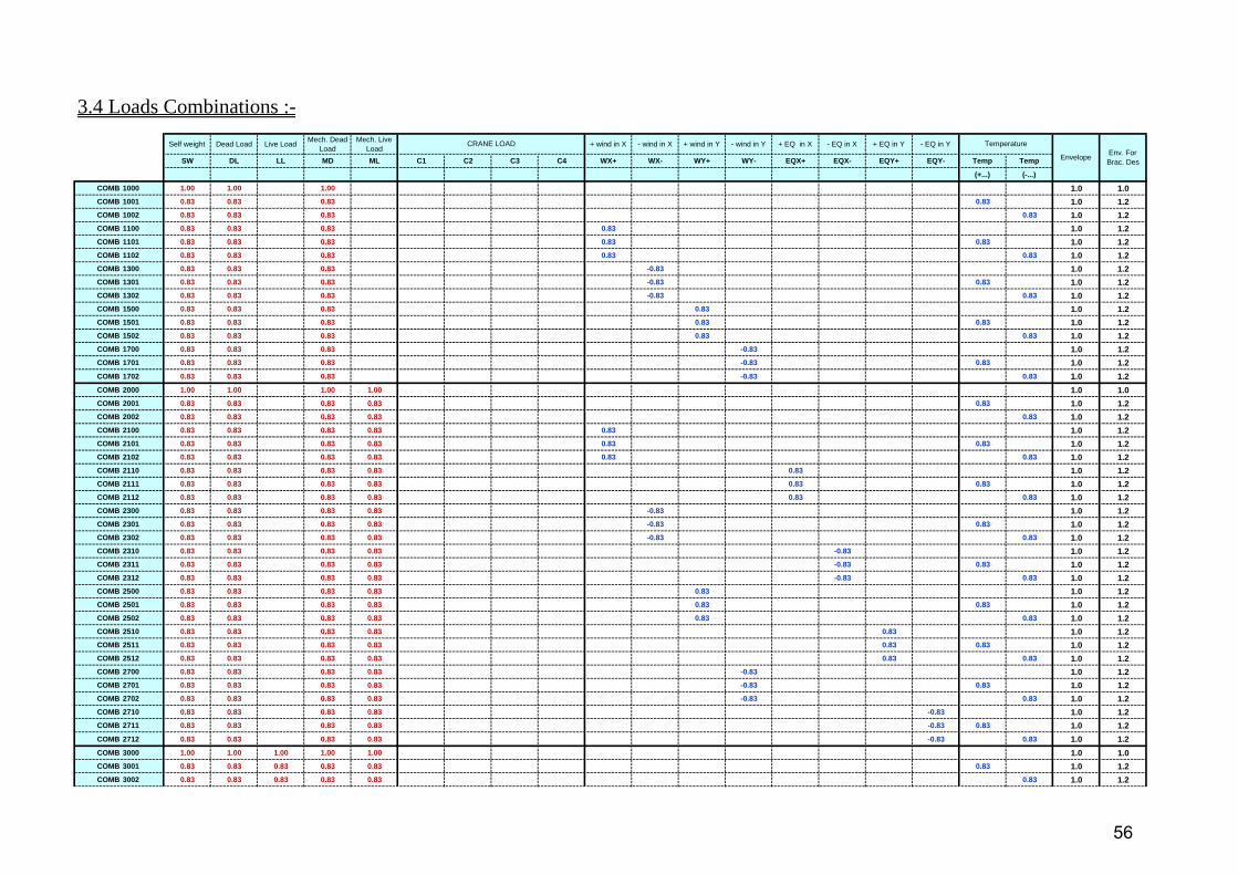
- The calculation will be done considering working stress design method. - For evaluating the maximum stress in elements, the straining actions will be calculated for two cases:
Case :Primary stresses due to ……...dead loads + live loads In design the stresses in members due to case should not exceed the allowable stresses.
Case :Primary and additional stresses due to ………Case loads + Secondary Loads
- Design of connection will be based on bearing type bolts.
3.2 Main Assumptions
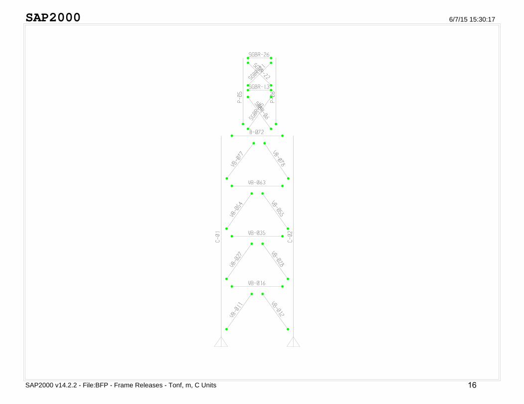
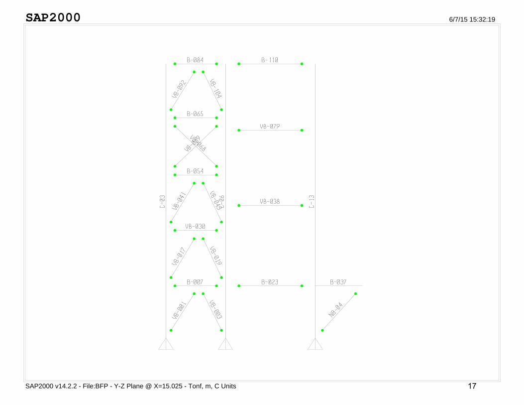
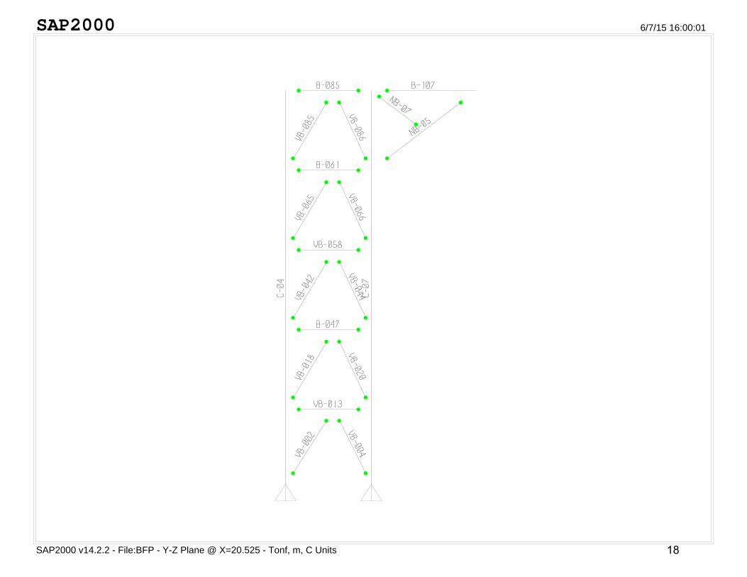
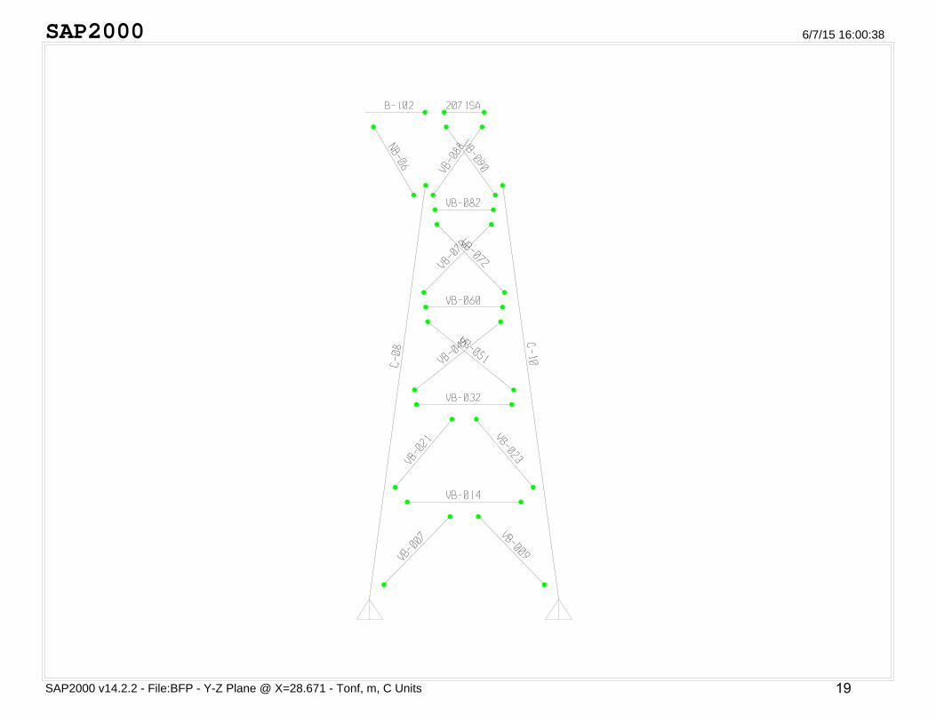
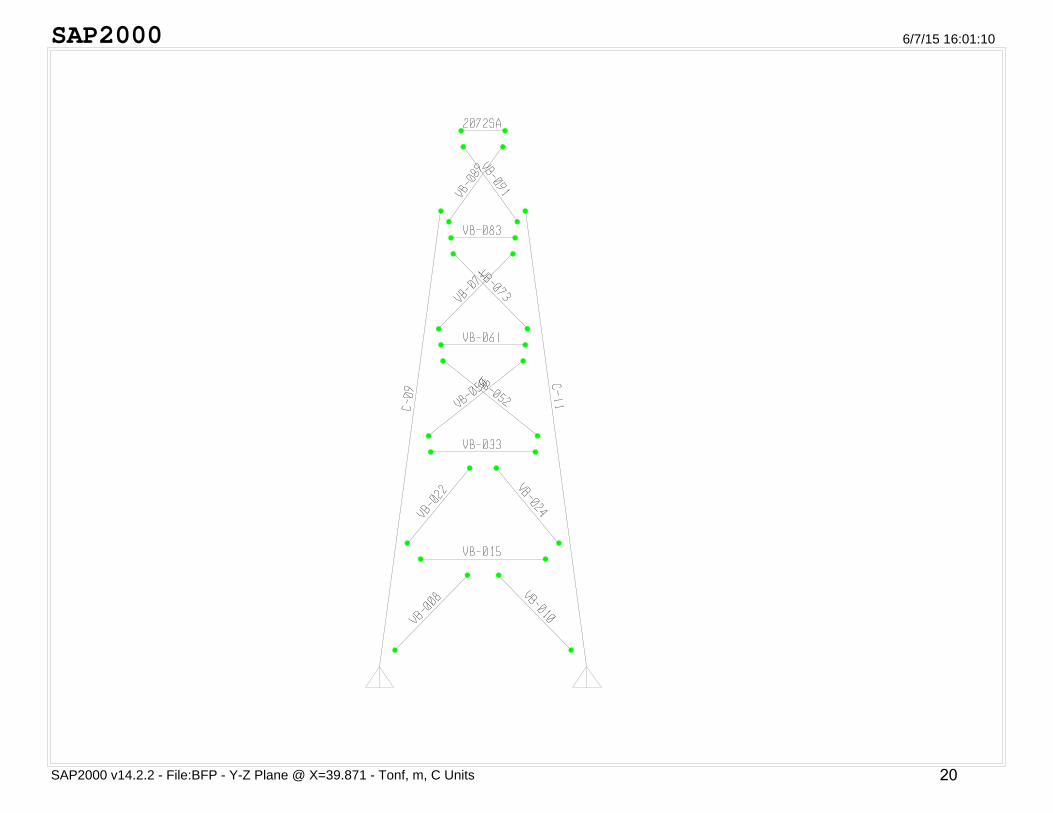
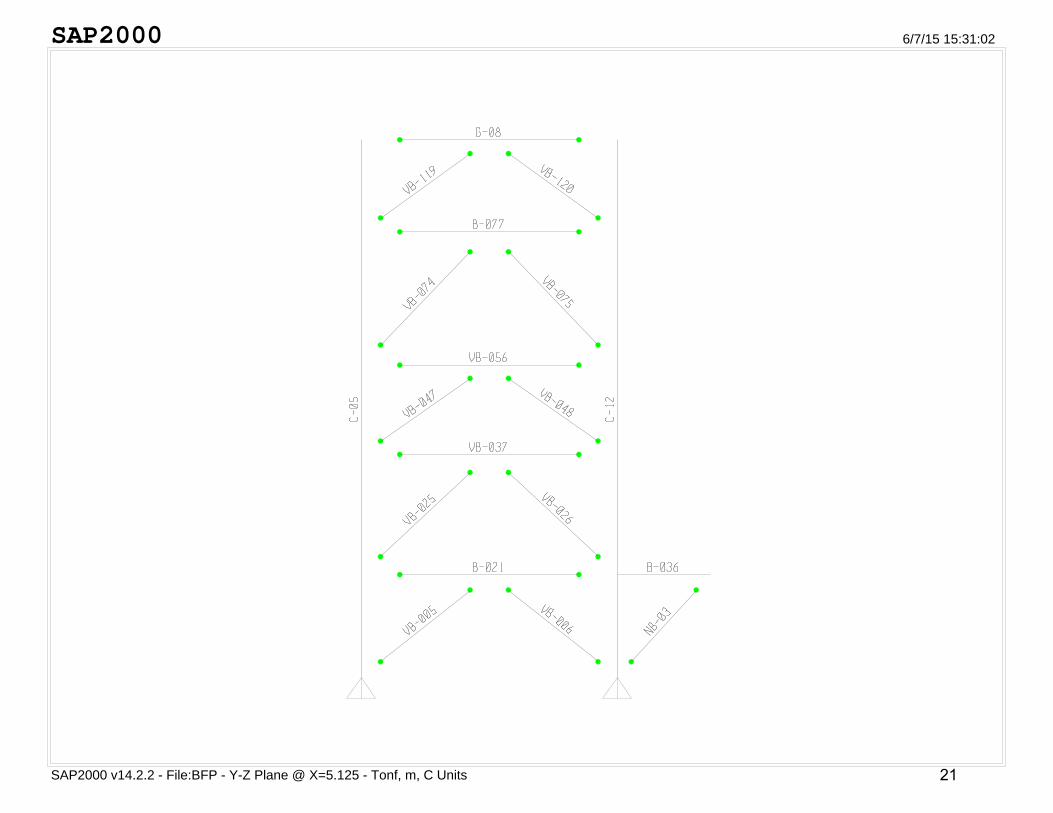
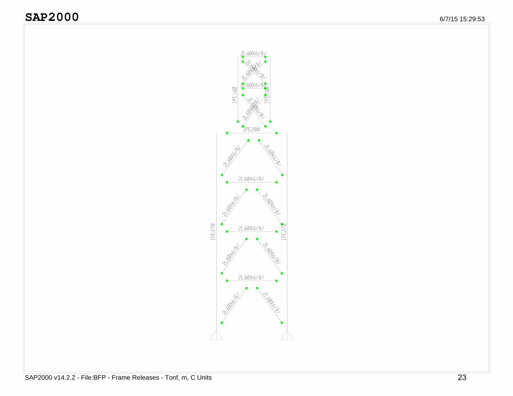
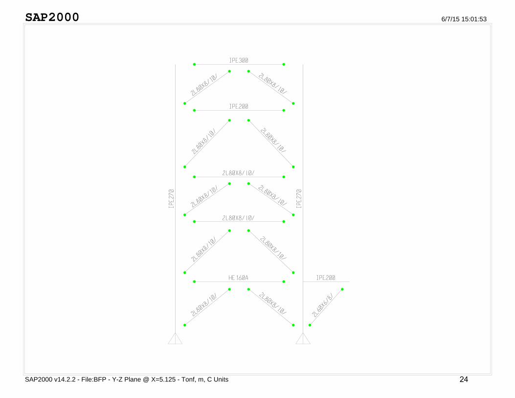
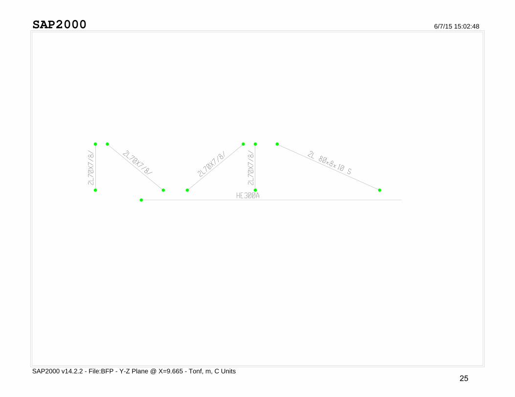
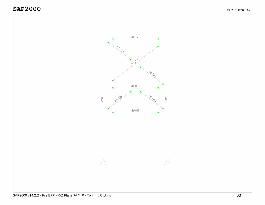
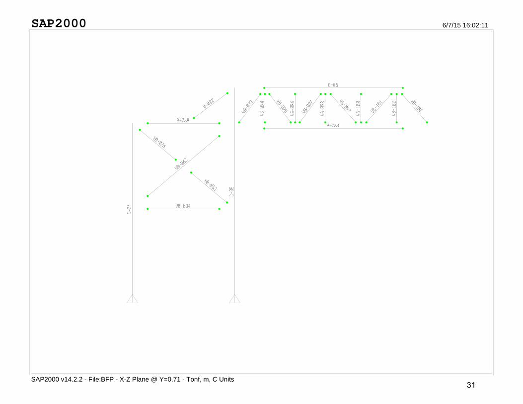
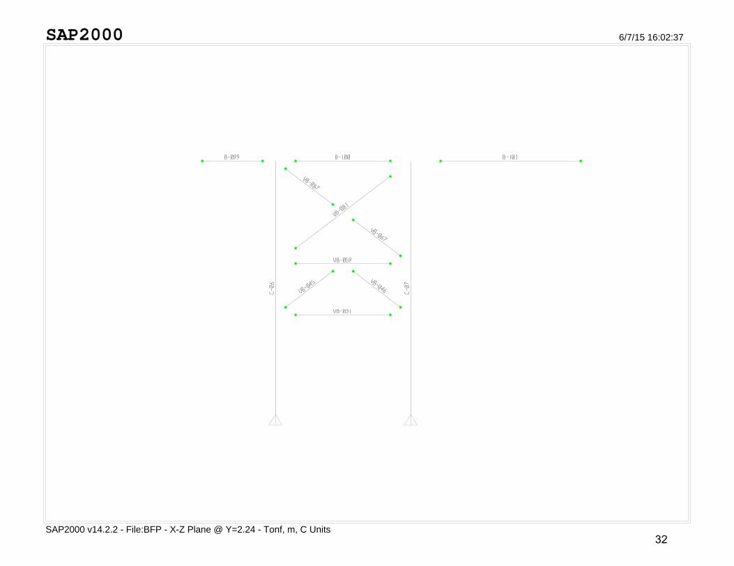
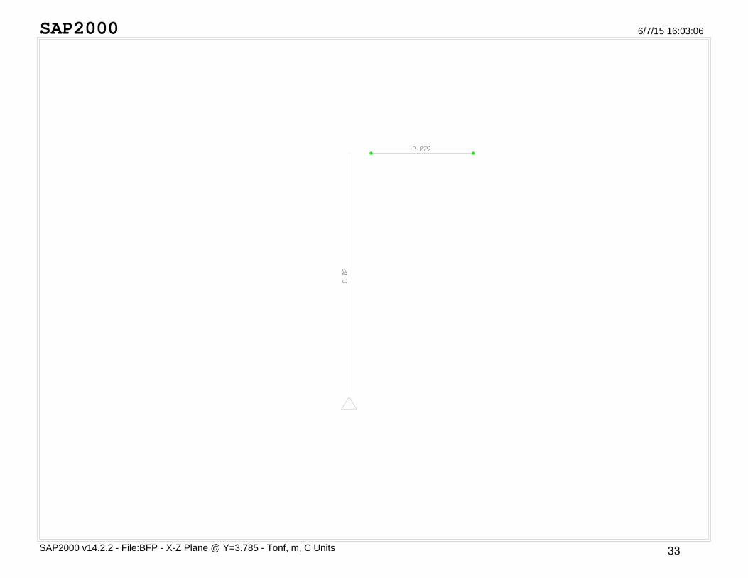
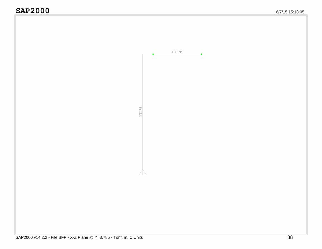
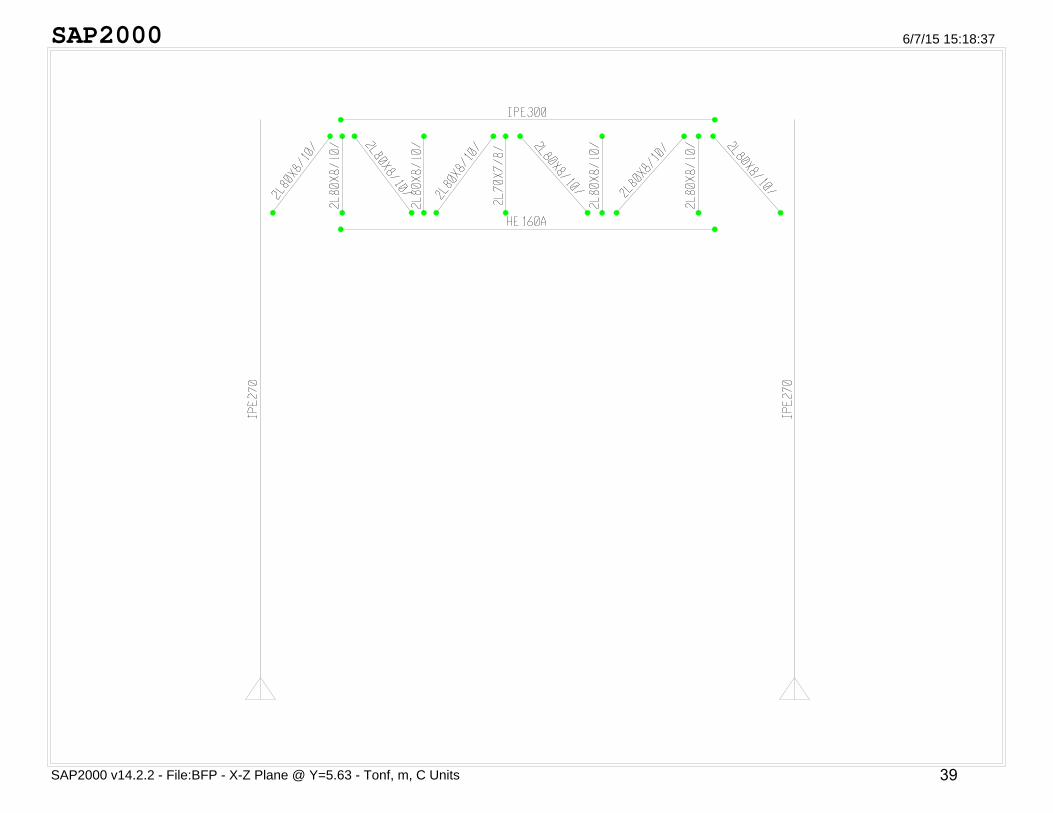
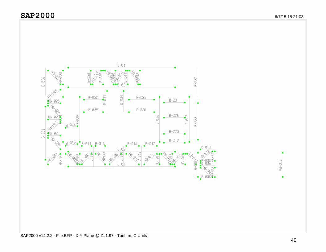
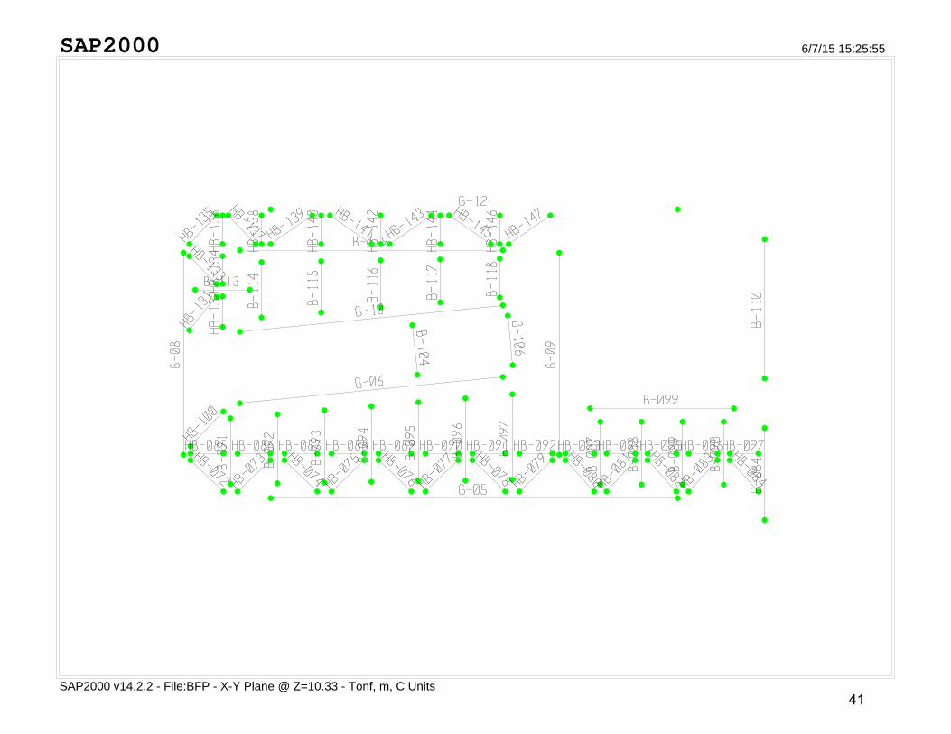
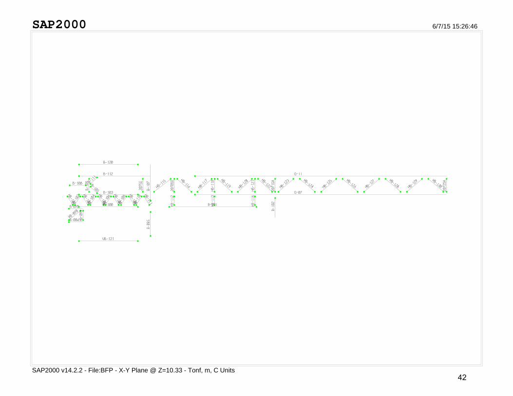
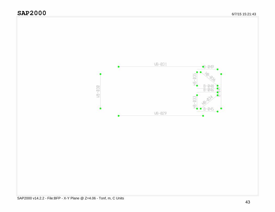
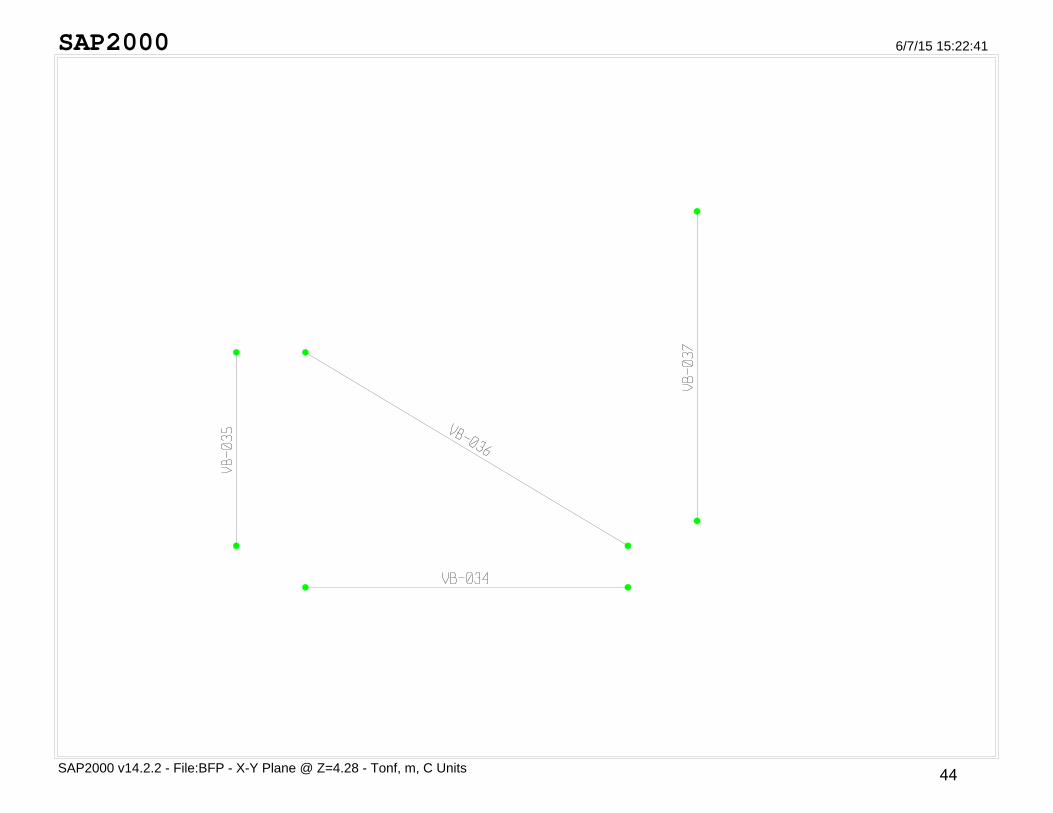
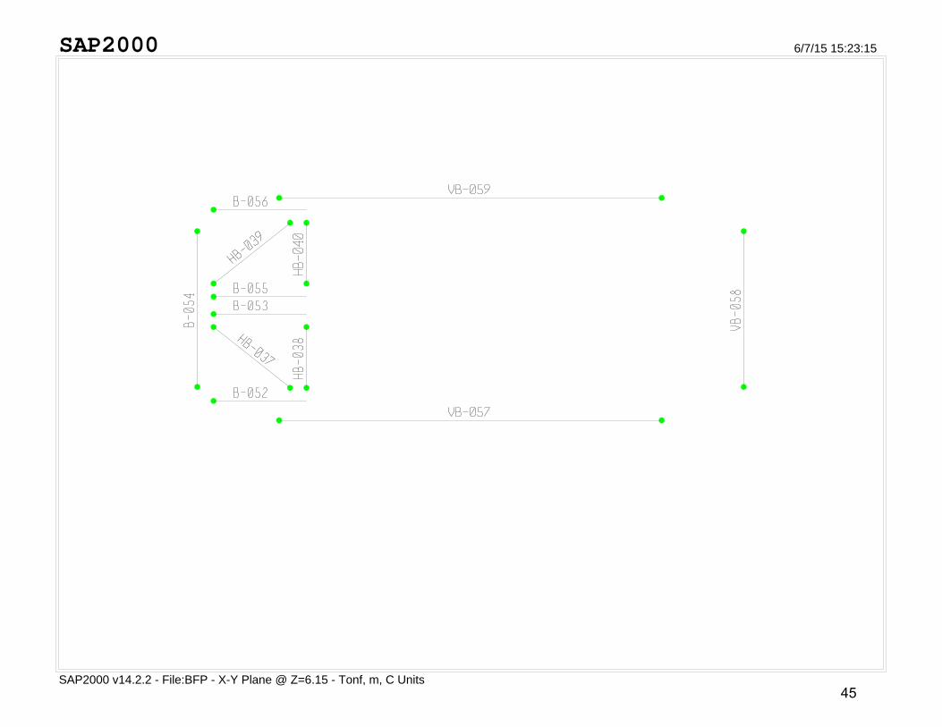
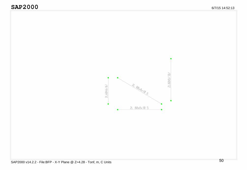
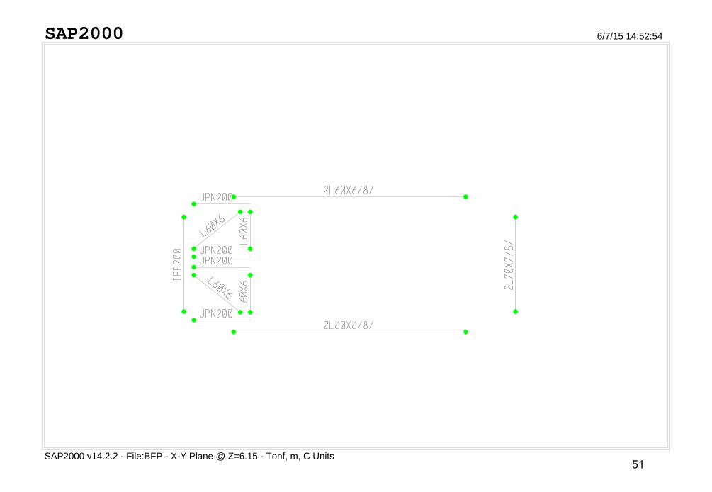
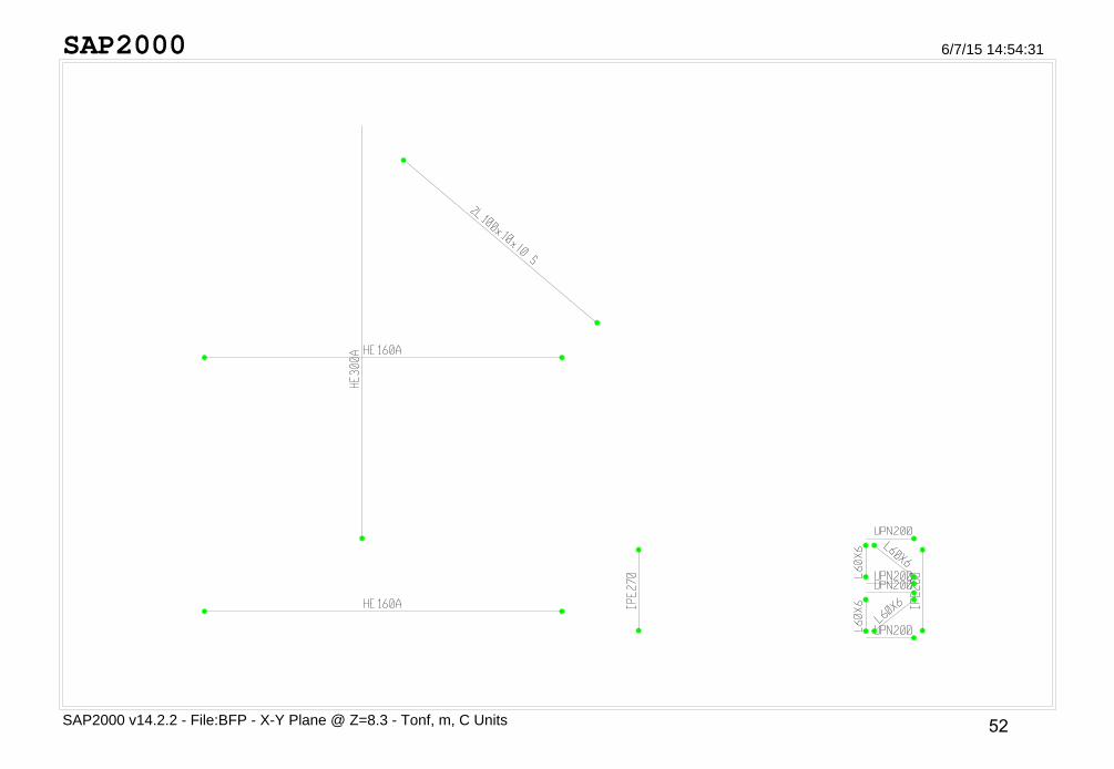
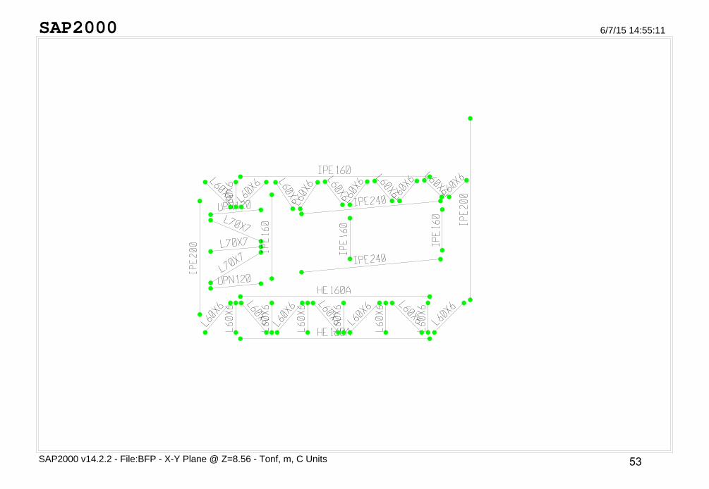
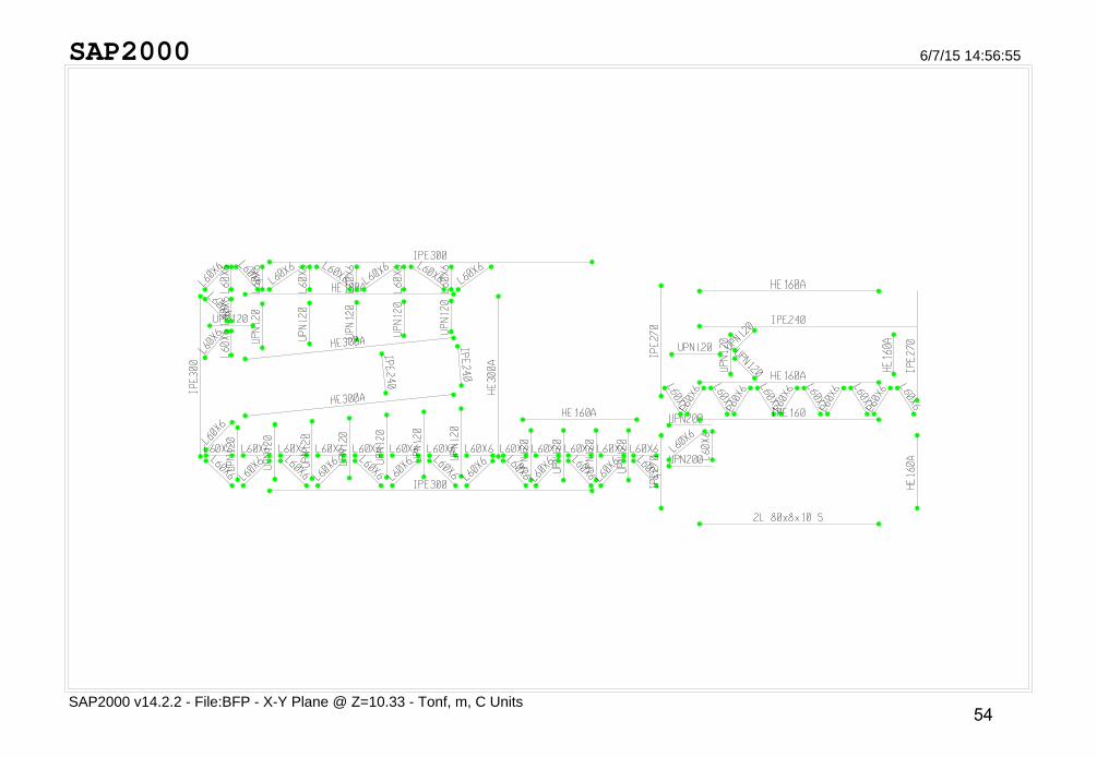
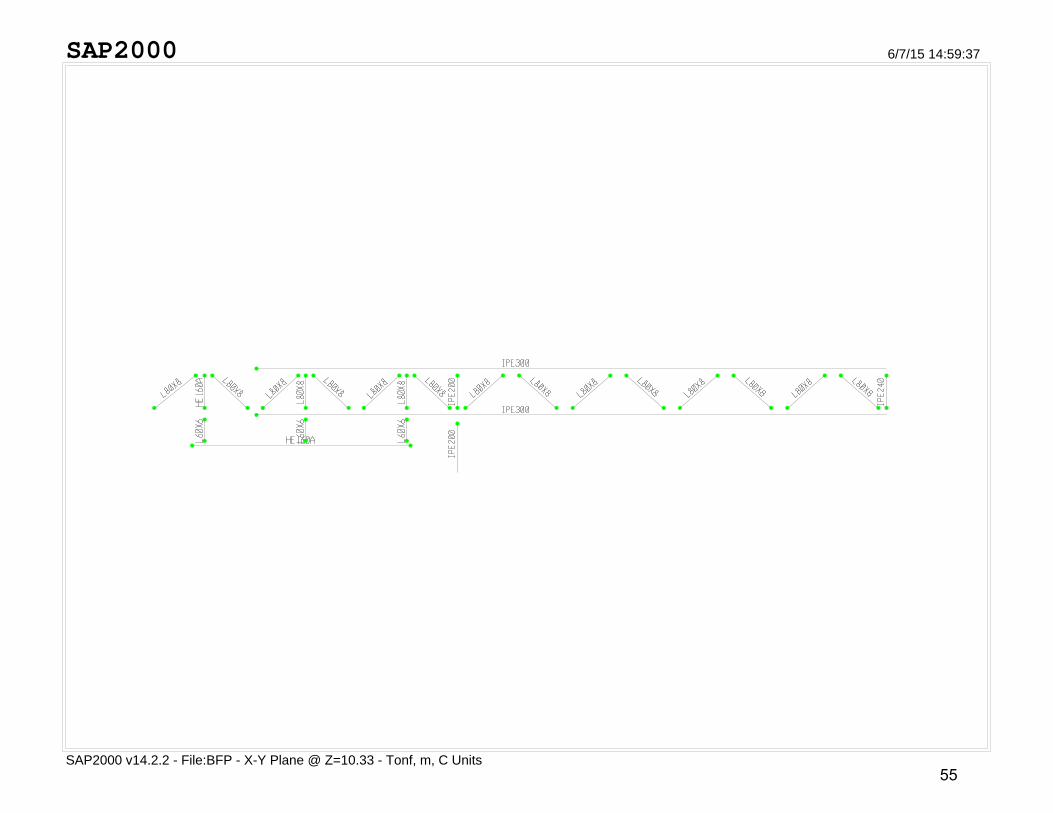
3.3 Model Configuration
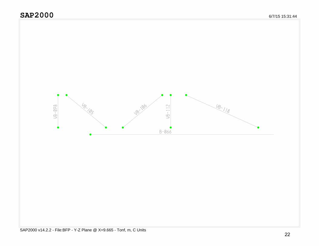
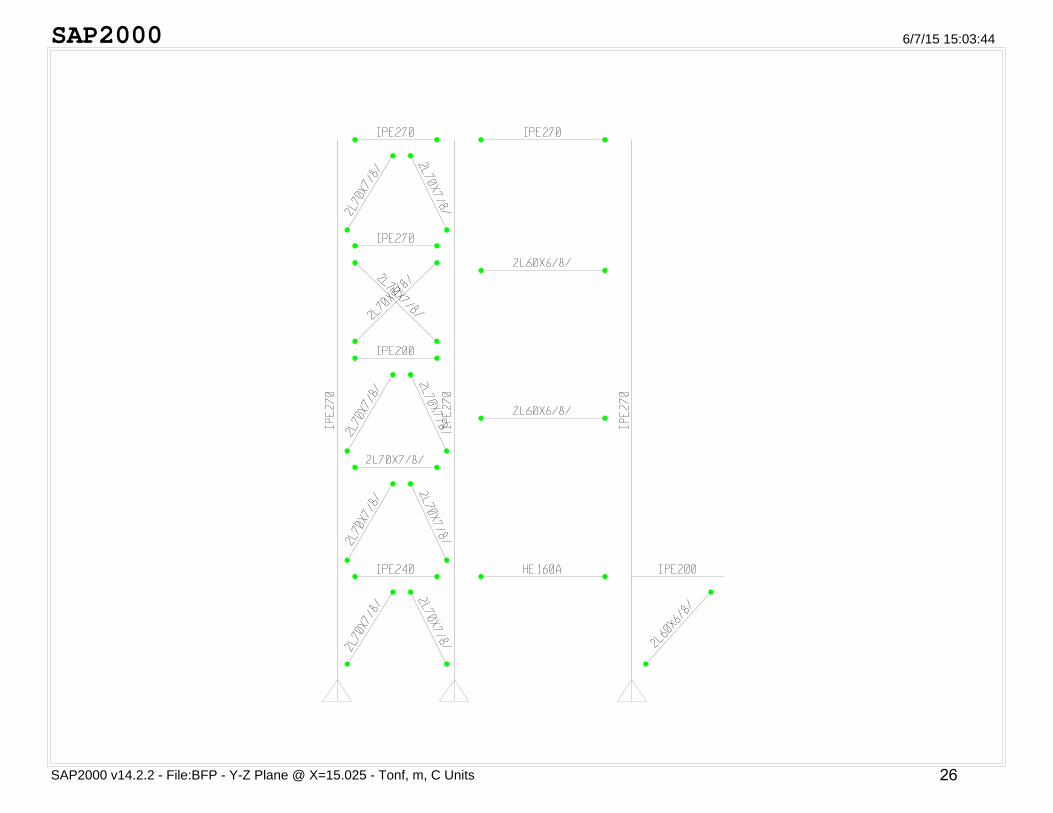
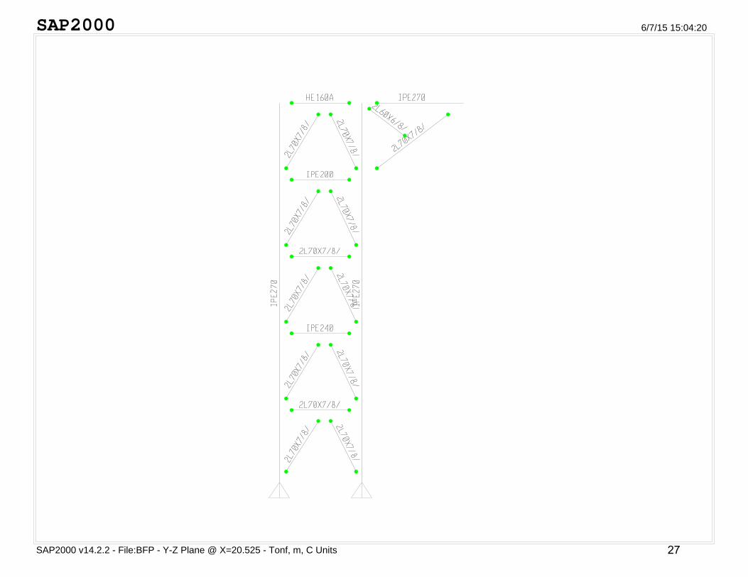
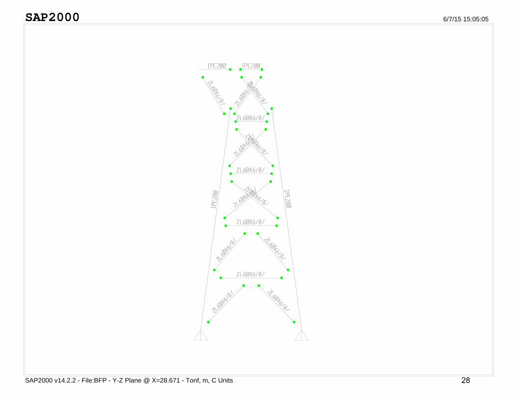
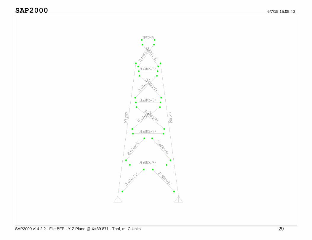
- Here below we will present the frame elements labels and profiles
In design the stresses in members due to case should not exceed the allowable stresses by more than 20%.
- For any moving loads where the impact effect is not considered in the given mechanical loads then load factors have to be added to consider the impact effect by increasing LL by 25%.
15
Page 18
SAP2000
SAP2000 v14.2.2 - File:BFP - Frame Releases - Tonf, m, C Units
6/7/15 15:30:17
16
Page 19
SAP2000
SAP2000 v14.2.2 - File:BFP - Y-Z Plane @ X=15.025 - Tonf, m, C Units
6/7/15 15:32:19
17
Page 20
SAP2000
SAP2000 v14.2.2 - File:BFP - Y-Z Plane @ X=20.525 - Tonf, m, C Units
6/7/15 16:00:01
18
Page 21
SAP2000
SAP2000 v14.2.2 - File:BFP - Y-Z Plane @ X=28.671 - Tonf, m, C Units
6/7/15 16:00:38
19
Page 22
SAP2000
SAP2000 v14.2.2 - File:BFP - Y-Z Plane @ X=39.871 - Tonf, m, C Units
6/7/15 16:01:10
20
Page 23
SAP2000
SAP2000 v14.2.2 - File:BFP - Y-Z Plane @ X=5.125 - Tonf, m, C Units
6/7/15 15:31:02
21
Page 24
SAP2000
SAP2000 v14.2.2 - File:BFP - Y-Z Plane @ X=9.665 - Tonf, m, C Units
6/7/15 15:31:44
22
Page 25
SAP2000
SAP2000 v14.2.2 - File:BFP - Frame Releases - Tonf, m, C Units
6/7/15 15:29:53
23
Page 26
SAP2000
SAP2000 v14.2.2 - File:BFP - Y-Z Plane @ X=5.125 - Tonf, m, C Units
6/7/15 15:01:53
24
Page 27
SAP2000
SAP2000 v14.2.2 - File:BFP - Y-Z Plane @ X=9.665 - Tonf, m, C Units
6/7/15 15:02:48
25
Page 28
SAP2000
SAP2000 v14.2.2 - File:BFP - Y-Z Plane @ X=15.025 - Tonf, m, C Units
6/7/15 15:03:44
26
Page 29
SAP2000
SAP2000 v14.2.2 - File:BFP - Y-Z Plane @ X=20.525 - Tonf, m, C Units
6/7/15 15:04:20
27
Page 30
SAP2000
SAP2000 v14.2.2 - File:BFP - Y-Z Plane @ X=28.671 - Tonf, m, C Units
6/7/15 15:05:05
28
Page 31
SAP2000
SAP2000 v14.2.2 - File:BFP - Y-Z Plane @ X=39.871 - Tonf, m, C Units
6/7/15 15:05:40
29
Page 32
SAP2000
SAP2000 v14.2.2 - File:BFP - X-Z Plane @ Y=0 - Tonf, m, C Units
6/7/15 16:01:47
30
Page 33
SAP2000
SAP2000 v14.2.2 - File:BFP - X-Z Plane @ Y=0.71 - Tonf, m, C Units
6/7/15 16:02:11
31
Page 34
SAP2000
SAP2000 v14.2.2 - File:BFP - X-Z Plane @ Y=2.24 - Tonf, m, C Units
6/7/15 16:02:37
32
Page 35
SAP2000
SAP2000 v14.2.2 - File:BFP - X-Z Plane @ Y=3.785 - Tonf, m, C Units
6/7/15 16:03:06
33
Page 36
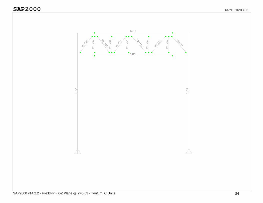
SAP2000
SAP2000 v14.2.2 - File:BFP - X-Z Plane @ Y=5.63 - Tonf, m, C Units
6/7/15 16:03:33
34
Page 37
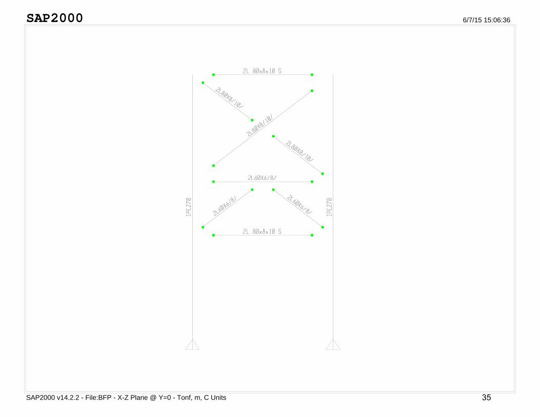
SAP2000
SAP2000 v14.2.2 - File:BFP - X-Z Plane @ Y=0 - Tonf, m, C Units
6/7/15 15:06:36
35
Page 38
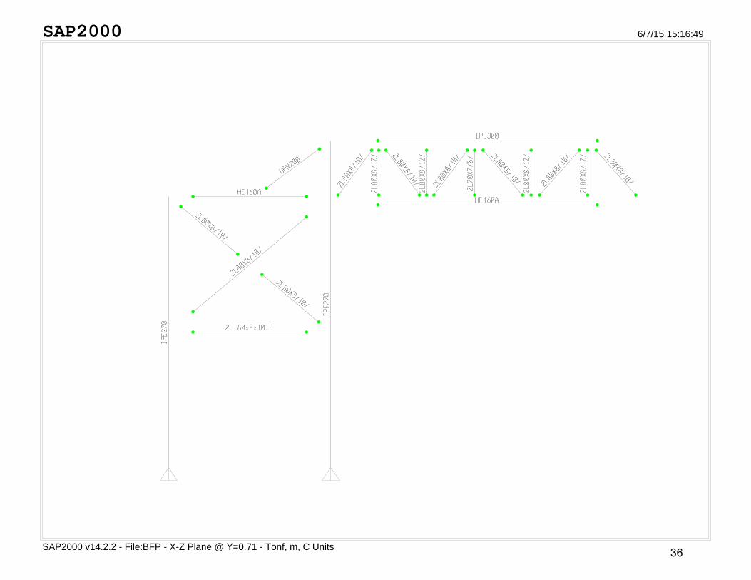
SAP2000
SAP2000 v14.2.2 - File:BFP - X-Z Plane @ Y=0.71 - Tonf, m, C Units
6/7/15 15:16:49
36
Page 39
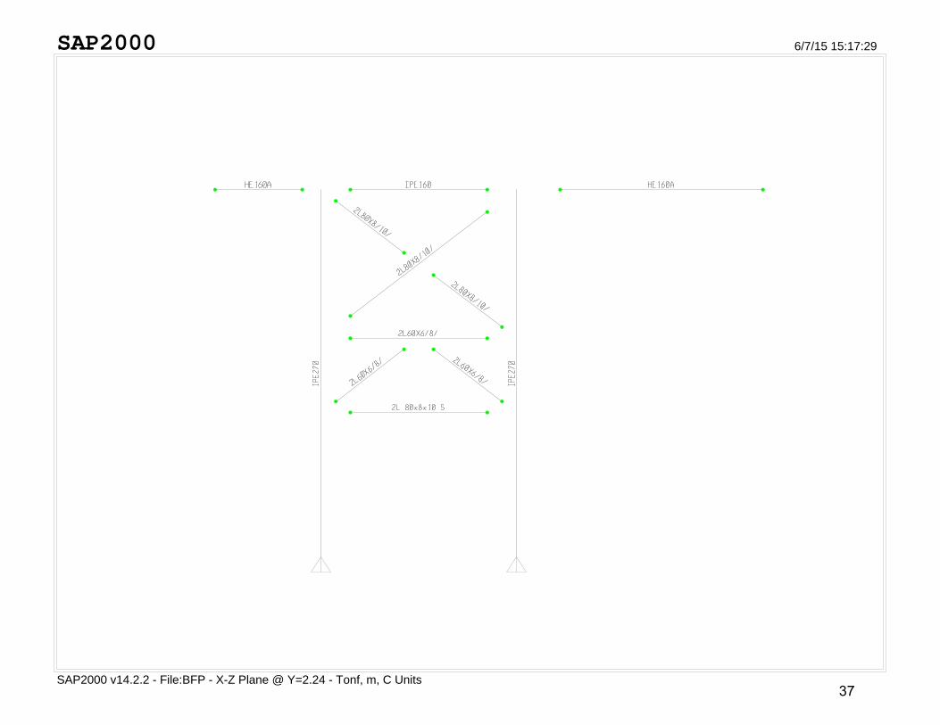
SAP2000
SAP2000 v14.2.2 - File:BFP - X-Z Plane @ Y=2.24 - Tonf, m, C Units
6/7/15 15:17:29
37
Page 40
SAP2000
SAP2000 v14.2.2 - File:BFP - X-Z Plane @ Y=3.785 - Tonf, m, C Units
6/7/15 15:18:05
38
Page 41
SAP2000
SAP2000 v14.2.2 - File:BFP - X-Z Plane @ Y=5.63 - Tonf, m, C Units
6/7/15 15:18:37
39
Page 42
SAP2000
SAP2000 v14.2.2 - File:BFP - X-Y Plane @ Z=1.97 - Tonf, m, C Units
6/7/15 15:21:03
40
Page 43
SAP2000
SAP2000 v14.2.2 - File:BFP - X-Y Plane @ Z=10.33 - Tonf, m, C Units
6/7/15 15:25:55
41
Page 44
SAP2000
SAP2000 v14.2.2 - File:BFP - X-Y Plane @ Z=10.33 - Tonf, m, C Units
6/7/15 15:26:46
42
Page 45
SAP2000
SAP2000 v14.2.2 - File:BFP - X-Y Plane @ Z=4.06 - Tonf, m, C Units
6/7/15 15:21:43
43
Page 46
SAP2000
SAP2000 v14.2.2 - File:BFP - X-Y Plane @ Z=4.28 - Tonf, m, C Units
6/7/15 15:22:41
44
Page 47
SAP2000
SAP2000 v14.2.2 - File:BFP - X-Y Plane @ Z=6.15 - Tonf, m, C Units
6/7/15 15:23:15
45
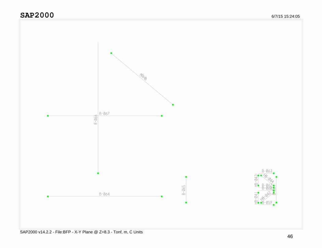
Page 48
SAP2000
SAP2000 v14.2.2 - File:BFP - X-Y Plane @ Z=8.3 - Tonf, m, C Units
6/7/15 15:24:05
46
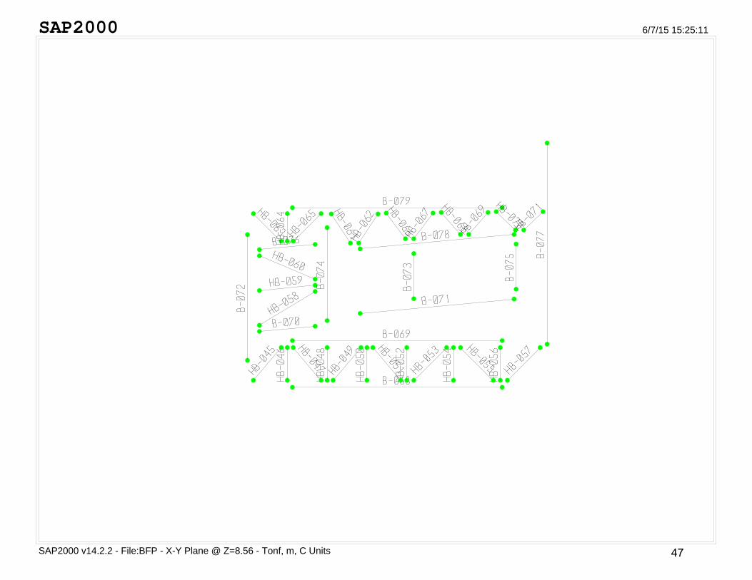
Page 49
SAP2000
SAP2000 v14.2.2 - File:BFP - X-Y Plane @ Z=8.56 - Tonf, m, C Units
6/7/15 15:25:11
47
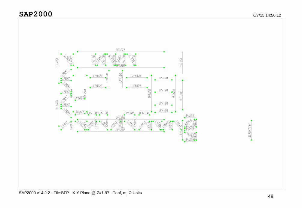
Page 50
SAP2000
SAP2000 v14.2.2 - File:BFP - X-Y Plane @ Z=1.97 - Tonf, m, C Units
6/7/15 14:50:12
48
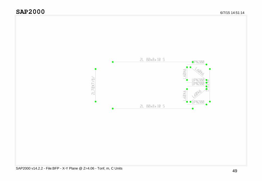
Page 51
SAP2000
SAP2000 v14.2.2 - File:BFP - X-Y Plane @ Z=4.06 - Tonf, m, C Units
6/7/15 14:51:14
49
Page 52
SAP2000
SAP2000 v14.2.2 - File:BFP - X-Y Plane @ Z=4.28 - Tonf, m, C Units
6/7/15 14:52:13
50
Page 53
SAP2000
SAP2000 v14.2.2 - File:BFP - X-Y Plane @ Z=6.15 - Tonf, m, C Units
6/7/15 14:52:54
51
Page 54
SAP2000
SAP2000 v14.2.2 - File:BFP - X-Y Plane @ Z=8.3 - Tonf, m, C Units
6/7/15 14:54:31
52
Page 55
SAP2000
SAP2000 v14.2.2 - File:BFP - X-Y Plane @ Z=8.56 - Tonf, m, C Units
6/7/15 14:55:11
53
Page 56
SAP2000
SAP2000 v14.2.2 - File:BFP - X-Y Plane @ Z=10.33 - Tonf, m, C Units
6/7/15 14:56:55
54
Page 57
SAP2000
SAP2000 v14.2.2 - File:BFP - X-Y Plane @ Z=10.33 - Tonf, m, C Units
6/7/15 14:59:37
55
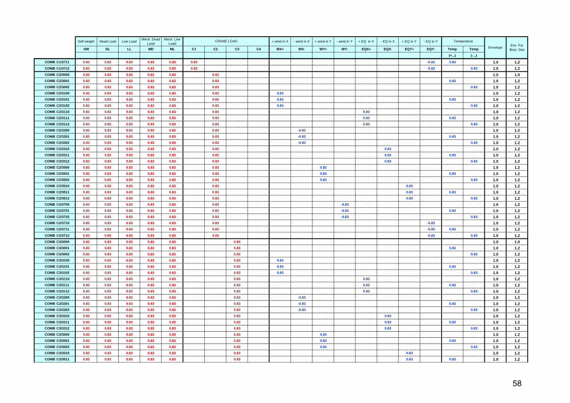
Page 58
Self weight Dead Load Live LoadMech. Dead
LoadMech. Live
Load+ wind in X - wind in X + wind in Y - wind in Y + EQ in X - EQ in X + EQ in Y - EQ in Y
SW DL LL MD ML C1 C2 C3 C4 WX+ WX- WY+ WY- EQX+ EQX- EQY+ EQY- Temp Temp
(+...) (-...)
COMB 1000 1.00 1.00 1.00 1.0 1.0
COMB 1001 0.83 0.83 0.83 0.83 1.0 1.2
COMB 1002 0.83 0.83 0.83 0.83 1.0 1.2
COMB 1100 0.83 0.83 0.83 0.83 1.0 1.2
COMB 1101 0.83 0.83 0.83 0.83 0.83 1.0 1.2
COMB 1102 0.83 0.83 0.83 0.83 0.83 1.0 1.2
COMB 1300 0.83 0.83 0.83 -0.83 1.0 1.2
COMB 1301 0.83 0.83 0.83 -0.83 0.83 1.0 1.2
COMB 1302 0.83 0.83 0.83 -0.83 0.83 1.0 1.2
COMB 1500 0.83 0.83 0.83 0.83 1.0 1.2
COMB 1501 0.83 0.83 0.83 0.83 0.83 1.0 1.2
COMB 1502 0.83 0.83 0.83 0.83 0.83 1.0 1.2
COMB 1700 0.83 0.83 0.83 -0.83 1.0 1.2
COMB 1701 0.83 0.83 0.83 -0.83 0.83 1.0 1.2
COMB 1702 0.83 0.83 0.83 -0.83 0.83 1.0 1.2
COMB 2000 1.00 1.00 1.00 1.00 1.0 1.0
COMB 2001 0.83 0.83 0.83 0.83 0.83 1.0 1.2
COMB 2002 0.83 0.83 0.83 0.83 0.83 1.0 1.2
COMB 2100 0.83 0.83 0.83 0.83 0.83 1.0 1.2
COMB 2101 0.83 0.83 0.83 0.83 0.83 0.83 1.0 1.2
COMB 2102 0.83 0.83 0.83 0.83 0.83 0.83 1.0 1.2
COMB 2110 0.83 0.83 0.83 0.83 0.83 1.0 1.2
COMB 2111 0.83 0.83 0.83 0.83 0.83 0.83 1.0 1.2
COMB 2112 0.83 0.83 0.83 0.83 0.83 0.83 1.0 1.2
COMB 2300 0.83 0.83 0.83 0.83 -0.83 1.0 1.2
COMB 2301 0.83 0.83 0.83 0.83 -0.83 0.83 1.0 1.2
COMB 2302 0.83 0.83 0.83 0.83 -0.83 0.83 1.0 1.2
COMB 2310 0.83 0.83 0.83 0.83 -0.83 1.0 1.2
COMB 2311 0.83 0.83 0.83 0.83 -0.83 0.83 1.0 1.2
COMB 2312 0.83 0.83 0.83 0.83 -0.83 0.83 1.0 1.2
COMB 2500 0.83 0.83 0.83 0.83 0.83 1.0 1.2
COMB 2501 0.83 0.83 0.83 0.83 0.83 0.83 1.0 1.2
COMB 2502 0.83 0.83 0.83 0.83 0.83 0.83 1.0 1.2
COMB 2510 0.83 0.83 0.83 0.83 0.83 1.0 1.2
COMB 2511 0.83 0.83 0.83 0.83 0.83 0.83 1.0 1.2
COMB 2512 0.83 0.83 0.83 0.83 0.83 0.83 1.0 1.2
COMB 2700 0.83 0.83 0.83 0.83 -0.83 1.0 1.2
COMB 2701 0.83 0.83 0.83 0.83 -0.83 0.83 1.0 1.2
COMB 2702 0.83 0.83 0.83 0.83 -0.83 0.83 1.0 1.2
COMB 2710 0.83 0.83 0.83 0.83 -0.83 1.0 1.2
COMB 2711 0.83 0.83 0.83 0.83 -0.83 0.83 1.0 1.2
COMB 2712 0.83 0.83 0.83 0.83 -0.83 0.83 1.0 1.2
COMB 3000 1.00 1.00 1.00 1.00 1.00 1.0 1.0
COMB 3001 0.83 0.83 0.83 0.83 0.83 0.83 1.0 1.2
COMB 3002 0.83 0.83 0.83 0.83 0.83 0.83 1.0 1.2
CRANE LOADEnv. For Brac. Des
Temperature
Envelope
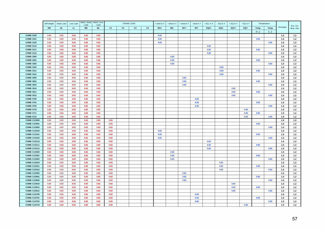
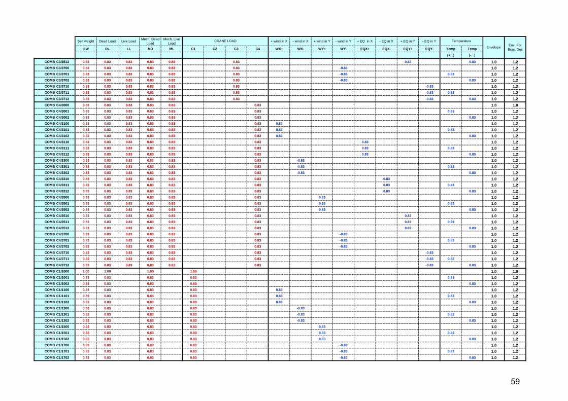
3.4 Loads Combinations :-
56
Page 59
Self weight Dead Load Live LoadMech. Dead
LoadMech. Live
Load+ wind in X - wind in X + wind in Y - wind in Y + EQ in X - EQ in X + EQ in Y - EQ in Y
SW DL LL MD ML C1 C2 C3 C4 WX+ WX- WY+ WY- EQX+ EQX- EQY+ EQY- Temp Temp
(+...) (-...)
CRANE LOADEnv. For Brac. Des
Temperature
Envelope
COMB 3100 0.83 0.83 0.83 0.83 0.83 0.83 1.0 1.2
COMB 3101 0.83 0.83 0.83 0.83 0.83 0.83 0.83 1.0 1.2
COMB 3102 0.83 0.83 0.83 0.83 0.83 0.83 0.83 1.0 1.2
COMB 3110 0.83 0.83 0.83 0.83 0.83 0.83 1.0 1.2
COMB 3111 0.83 0.83 0.83 0.83 0.83 0.83 0.83 1.0 1.2
COMB 3112 0.83 0.83 0.83 0.83 0.83 0.83 0.83 1.0 1.2
COMB 3300 0.83 0.83 0.83 0.83 0.83 -0.83 1.0 1.2
COMB 3301 0.83 0.83 0.83 0.83 0.83 -0.83 0.83 1.0 1.2
COMB 3302 0.83 0.83 0.83 0.83 0.83 -0.83 0.83 1.0 1.2
COMB 3310 0.83 0.83 0.83 0.83 0.83 -0.83 1.0 1.2
COMB 3311 0.83 0.83 0.83 0.83 0.83 -0.83 0.83 1.0 1.2
COMB 3312 0.83 0.83 0.83 0.83 0.83 -0.83 0.83 1.0 1.2
COMB 3500 0.83 0.83 0.83 0.83 0.83 0.83 1.0 1.2
COMB 3501 0.83 0.83 0.83 0.83 0.83 0.83 0.83 1.0 1.2
COMB 3502 0.83 0.83 0.83 0.83 0.83 0.83 0.83 1.0 1.2
COMB 3510 0.83 0.83 0.83 0.83 0.83 0.83 1.0 1.2
COMB 3511 0.83 0.83 0.83 0.83 0.83 0.83 0.83 1.0 1.2
COMB 3512 0.83 0.83 0.83 0.83 0.83 0.83 0.83 1.0 1.2
COMB 3700 0.83 0.83 0.83 0.83 0.83 -0.83 1.0 1.2
COMB 3701 0.83 0.83 0.83 0.83 0.83 -0.83 0.83 1.0 1.2
COMB 3702 0.83 0.83 0.83 0.83 0.83 -0.83 0.83 1.0 1.2
COMB 3710 0.83 0.83 0.83 0.83 0.83 -0.83 1.0 1.2
COMB 3711 0.83 0.83 0.83 0.83 0.83 -0.83 0.83 1.0 1.2
COMB 3712 0.83 0.83 0.83 0.83 0.83 -0.83 0.83 1.0 1.2
COMB C1/3000 0.83 0.83 0.83 0.83 0.83 0.83 1.0 1.0
COMB C1/3001 0.83 0.83 0.83 0.83 0.83 0.83 0.83 1.0 1.2
COMB C1/3002 0.83 0.83 0.83 0.83 0.83 0.83 0.83 1.0 1.2
COMB C1/3100 0.83 0.83 0.83 0.83 0.83 0.83 0.83 1.0 1.2
COMB C1/3101 0.83 0.83 0.83 0.83 0.83 0.83 0.83 0.83 1.0 1.2
COMB C1/3102 0.83 0.83 0.83 0.83 0.83 0.83 0.83 0.83 1.0 1.2
COMB C1/3110 0.83 0.83 0.83 0.83 0.83 0.83 0.83 1.0 1.2
COMB C1/3111 0.83 0.83 0.83 0.83 0.83 0.83 0.83 0.83 1.0 1.2
COMB C1/3112 0.83 0.83 0.83 0.83 0.83 0.83 0.83 0.83 1.0 1.2
COMB C1/3300 0.83 0.83 0.83 0.83 0.83 0.83 -0.83 1.0 1.2
COMB C1/3301 0.83 0.83 0.83 0.83 0.83 0.83 -0.83 0.83 1.0 1.2
COMB C1/3302 0.83 0.83 0.83 0.83 0.83 0.83 -0.83 0.83 1.0 1.2
COMB C1/3310 0.83 0.83 0.83 0.83 0.83 0.83 0.83 1.0 1.2
COMB C1/3311 0.83 0.83 0.83 0.83 0.83 0.83 0.83 0.83 1.0 1.2
COMB C1/3312 0.83 0.83 0.83 0.83 0.83 0.83 0.83 0.83 1.0 1.2
COMB C1/3500 0.83 0.83 0.83 0.83 0.83 0.83 0.83 1.0 1.2
COMB C1/3501 0.83 0.83 0.83 0.83 0.83 0.83 0.83 0.83 1.0 1.2
COMB C1/3502 0.83 0.83 0.83 0.83 0.83 0.83 0.83 0.83 1.0 1.2
COMB C1/3510 0.83 0.83 0.83 0.83 0.83 0.83 0.83 1.0 1.2
COMB C1/3511 0.83 0.83 0.83 0.83 0.83 0.83 0.83 0.83 1.0 1.2
COMB C1/3512 0.83 0.83 0.83 0.83 0.83 0.83 0.83 0.83 1.0 1.2
COMB C1/3700 0.83 0.83 0.83 0.83 0.83 0.83 -0.83 1.0 1.2
COMB C1/3701 0.83 0.83 0.83 0.83 0.83 0.83 -0.83 0.83 1.0 1.2
COMB C1/3702 0.83 0.83 0.83 0.83 0.83 0.83 -0.83 0.83 1.0 1.2
COMB C1/3710 0.83 0.83 0.83 0.83 0.83 0.83 -0.83 1.0 1.2
57
Page 60
Self weight Dead Load Live LoadMech. Dead
LoadMech. Live
Load+ wind in X - wind in X + wind in Y - wind in Y + EQ in X - EQ in X + EQ in Y - EQ in Y
SW DL LL MD ML C1 C2 C3 C4 WX+ WX- WY+ WY- EQX+ EQX- EQY+ EQY- Temp Temp
(+...) (-...)
CRANE LOADEnv. For Brac. Des
Temperature
Envelope
COMB C1/3711 0.83 0.83 0.83 0.83 0.83 0.83 -0.83 0.83 1.0 1.2
COMB C1/3712 0.83 0.83 0.83 0.83 0.83 0.83 -0.83 0.83 1.0 1.2
COMB C2/3000 0.83 0.83 0.83 0.83 0.83 0.83 1.0 1.0
COMB C2/3001 0.83 0.83 0.83 0.83 0.83 0.83 0.83 1.0 1.2
COMB C2/3002 0.83 0.83 0.83 0.83 0.83 0.83 0.83 1.0 1.2
COMB C2/3100 0.83 0.83 0.83 0.83 0.83 0.83 0.83 1.0 1.2
COMB C2/3101 0.83 0.83 0.83 0.83 0.83 0.83 0.83 0.83 1.0 1.2
COMB C2/3102 0.83 0.83 0.83 0.83 0.83 0.83 0.83 0.83 1.0 1.2
COMB C2/3110 0.83 0.83 0.83 0.83 0.83 0.83 0.83 1.0 1.2
COMB C2/3111 0.83 0.83 0.83 0.83 0.83 0.83 0.83 0.83 1.0 1.2
COMB C2/3112 0.83 0.83 0.83 0.83 0.83 0.83 0.83 0.83 1.0 1.2
COMB C2/3300 0.83 0.83 0.83 0.83 0.83 0.83 -0.83 1.0 1.2
COMB C2/3301 0.83 0.83 0.83 0.83 0.83 0.83 -0.83 0.83 1.0 1.2
COMB C2/3302 0.83 0.83 0.83 0.83 0.83 0.83 -0.83 0.83 1.0 1.2
COMB C2/3310 0.83 0.83 0.83 0.83 0.83 0.83 0.83 1.0 1.2
COMB C2/3311 0.83 0.83 0.83 0.83 0.83 0.83 0.83 0.83 1.0 1.2
COMB C2/3312 0.83 0.83 0.83 0.83 0.83 0.83 0.83 0.83 1.0 1.2
COMB C2/3500 0.83 0.83 0.83 0.83 0.83 0.83 0.83 1.0 1.2
COMB C2/3501 0.83 0.83 0.83 0.83 0.83 0.83 0.83 0.83 1.0 1.2
COMB C2/3502 0.83 0.83 0.83 0.83 0.83 0.83 0.83 0.83 1.0 1.2
COMB C2/3510 0.83 0.83 0.83 0.83 0.83 0.83 0.83 1.0 1.2
COMB C2/3511 0.83 0.83 0.83 0.83 0.83 0.83 0.83 0.83 1.0 1.2
COMB C2/3512 0.83 0.83 0.83 0.83 0.83 0.83 0.83 0.83 1.0 1.2
COMB C2/3700 0.83 0.83 0.83 0.83 0.83 0.83 -0.83 1.0 1.2
COMB C2/3701 0.83 0.83 0.83 0.83 0.83 0.83 -0.83 0.83 1.0 1.2
COMB C2/3702 0.83 0.83 0.83 0.83 0.83 0.83 -0.83 0.83 1.0 1.2
COMB C2/3710 0.83 0.83 0.83 0.83 0.83 0.83 -0.83 1.0 1.2
COMB C2/3711 0.83 0.83 0.83 0.83 0.83 0.83 -0.83 0.83 1.0 1.2
COMB C2/3712 0.83 0.83 0.83 0.83 0.83 0.83 -0.83 0.83 1.0 1.2
COMB C3/3000 0.83 0.83 0.83 0.83 0.83 0.83 1.0 1.0
COMB C3/3001 0.83 0.83 0.83 0.83 0.83 0.83 0.83 1.0 1.2
COMB C3/3002 0.83 0.83 0.83 0.83 0.83 0.83 0.83 1.0 1.2
COMB C3/3100 0.83 0.83 0.83 0.83 0.83 0.83 0.83 1.0 1.2
COMB C3/3101 0.83 0.83 0.83 0.83 0.83 0.83 0.83 0.83 1.0 1.2
COMB C3/3102 0.83 0.83 0.83 0.83 0.83 0.83 0.83 0.83 1.0 1.2
COMB C3/3110 0.83 0.83 0.83 0.83 0.83 0.83 0.83 1.0 1.2
COMB C3/3111 0.83 0.83 0.83 0.83 0.83 0.83 0.83 0.83 1.0 1.2
COMB C3/3112 0.83 0.83 0.83 0.83 0.83 0.83 0.83 0.83 1.0 1.2
COMB C3/3300 0.83 0.83 0.83 0.83 0.83 0.83 -0.83 1.0 1.2
COMB C3/3301 0.83 0.83 0.83 0.83 0.83 0.83 -0.83 0.83 1.0 1.2
COMB C3/3302 0.83 0.83 0.83 0.83 0.83 0.83 -0.83 0.83 1.0 1.2
COMB C3/3310 0.83 0.83 0.83 0.83 0.83 0.83 0.83 1.0 1.2
COMB C3/3311 0.83 0.83 0.83 0.83 0.83 0.83 0.83 0.83 1.0 1.2
COMB C3/3312 0.83 0.83 0.83 0.83 0.83 0.83 0.83 0.83 1.0 1.2
COMB C3/3500 0.83 0.83 0.83 0.83 0.83 0.83 0.83 1.0 1.2
COMB C3/3501 0.83 0.83 0.83 0.83 0.83 0.83 0.83 0.83 1.0 1.2
COMB C3/3502 0.83 0.83 0.83 0.83 0.83 0.83 0.83 0.83 1.0 1.2
COMB C3/3510 0.83 0.83 0.83 0.83 0.83 0.83 0.83 1.0 1.2
COMB C3/3511 0.83 0.83 0.83 0.83 0.83 0.83 0.83 0.83 1.0 1.2
58
Page 61
Self weight Dead Load Live LoadMech. Dead
LoadMech. Live
Load+ wind in X - wind in X + wind in Y - wind in Y + EQ in X - EQ in X + EQ in Y - EQ in Y
SW DL LL MD ML C1 C2 C3 C4 WX+ WX- WY+ WY- EQX+ EQX- EQY+ EQY- Temp Temp
(+...) (-...)
CRANE LOADEnv. For Brac. Des
Temperature
Envelope
COMB C3/3512 0.83 0.83 0.83 0.83 0.83 0.83 0.83 0.83 1.0 1.2
COMB C3/3700 0.83 0.83 0.83 0.83 0.83 0.83 -0.83 1.0 1.2
COMB C3/3701 0.83 0.83 0.83 0.83 0.83 0.83 -0.83 0.83 1.0 1.2
COMB C3/3702 0.83 0.83 0.83 0.83 0.83 0.83 -0.83 0.83 1.0 1.2
COMB C3/3710 0.83 0.83 0.83 0.83 0.83 0.83 -0.83 1.0 1.2
COMB C3/3711 0.83 0.83 0.83 0.83 0.83 0.83 -0.83 0.83 1.0 1.2
COMB C3/3712 0.83 0.83 0.83 0.83 0.83 0.83 -0.83 0.83 1.0 1.2
COMB C4/3000 0.83 0.83 0.83 0.83 0.83 0.83 1.0 1.0
COMB C4/3001 0.83 0.83 0.83 0.83 0.83 0.83 0.83 1.0 1.2
COMB C4/3002 0.83 0.83 0.83 0.83 0.83 0.83 0.83 1.0 1.2
COMB C4/3100 0.83 0.83 0.83 0.83 0.83 0.83 0.83 1.0 1.2
COMB C4/3101 0.83 0.83 0.83 0.83 0.83 0.83 0.83 0.83 1.0 1.2
COMB C4/3102 0.83 0.83 0.83 0.83 0.83 0.83 0.83 0.83 1.0 1.2
COMB C4/3110 0.83 0.83 0.83 0.83 0.83 0.83 0.83 1.0 1.2
COMB C4/3111 0.83 0.83 0.83 0.83 0.83 0.83 0.83 0.83 1.0 1.2
COMB C4/3112 0.83 0.83 0.83 0.83 0.83 0.83 0.83 0.83 1.0 1.2
COMB C4/3300 0.83 0.83 0.83 0.83 0.83 0.83 -0.83 1.0 1.2
COMB C4/3301 0.83 0.83 0.83 0.83 0.83 0.83 -0.83 0.83 1.0 1.2
COMB C4/3302 0.83 0.83 0.83 0.83 0.83 0.83 -0.83 0.83 1.0 1.2
COMB C4/3310 0.83 0.83 0.83 0.83 0.83 0.83 0.83 1.0 1.2
COMB C4/3311 0.83 0.83 0.83 0.83 0.83 0.83 0.83 0.83 1.0 1.2
COMB C4/3312 0.83 0.83 0.83 0.83 0.83 0.83 0.83 0.83 1.0 1.2
COMB C4/3500 0.83 0.83 0.83 0.83 0.83 0.83 0.83 1.0 1.2
COMB C4/3501 0.83 0.83 0.83 0.83 0.83 0.83 0.83 0.83 1.0 1.2
COMB C4/3502 0.83 0.83 0.83 0.83 0.83 0.83 0.83 0.83 1.0 1.2
COMB C4/3510 0.83 0.83 0.83 0.83 0.83 0.83 0.83 1.0 1.2
COMB C4/3511 0.83 0.83 0.83 0.83 0.83 0.83 0.83 0.83 1.0 1.2
COMB C4/3512 0.83 0.83 0.83 0.83 0.83 0.83 0.83 0.83 1.0 1.2
COMB C4/3700 0.83 0.83 0.83 0.83 0.83 0.83 -0.83 1.0 1.2
COMB C4/3701 0.83 0.83 0.83 0.83 0.83 0.83 -0.83 0.83 1.0 1.2
COMB C4/3702 0.83 0.83 0.83 0.83 0.83 0.83 -0.83 0.83 1.0 1.2
COMB C4/3710 0.83 0.83 0.83 0.83 0.83 0.83 -0.83 1.0 1.2
COMB C4/3711 0.83 0.83 0.83 0.83 0.83 0.83 -0.83 0.83 1.0 1.2
COMB C4/3712 0.83 0.83 0.83 0.83 0.83 0.83 -0.83 0.83 1.0 1.2
COMB C1/1000 1.00 1.00 1.00 1.00 1.0 1.0
COMB C1/1001 0.83 0.83 0.83 0.83 0.83 1.0 1.2
COMB C1/1002 0.83 0.83 0.83 0.83 0.83 1.0 1.2
COMB C1/1100 0.83 0.83 0.83 0.83 0.83 1.0 1.2
COMB C1/1101 0.83 0.83 0.83 0.83 0.83 0.83 1.0 1.2
COMB C1/1102 0.83 0.83 0.83 0.83 0.83 0.83 1.0 1.2
COMB C1/1300 0.83 0.83 0.83 0.83 -0.83 1.0 1.2
COMB C1/1301 0.83 0.83 0.83 0.83 -0.83 0.83 1.0 1.2
COMB C1/1302 0.83 0.83 0.83 0.83 -0.83 0.83 1.0 1.2
COMB C1/1500 0.83 0.83 0.83 0.83 0.83 1.0 1.2
COMB C1/1501 0.83 0.83 0.83 0.83 0.83 0.83 1.0 1.2
COMB C1/1502 0.83 0.83 0.83 0.83 0.83 0.83 1.0 1.2
COMB C1/1700 0.83 0.83 0.83 0.83 -0.83 1.0 1.2
COMB C1/1701 0.83 0.83 0.83 0.83 -0.83 0.83 1.0 1.2
COMB C1/1702 0.83 0.83 0.83 0.83 -0.83 0.83 1.0 1.2
59
Page 62
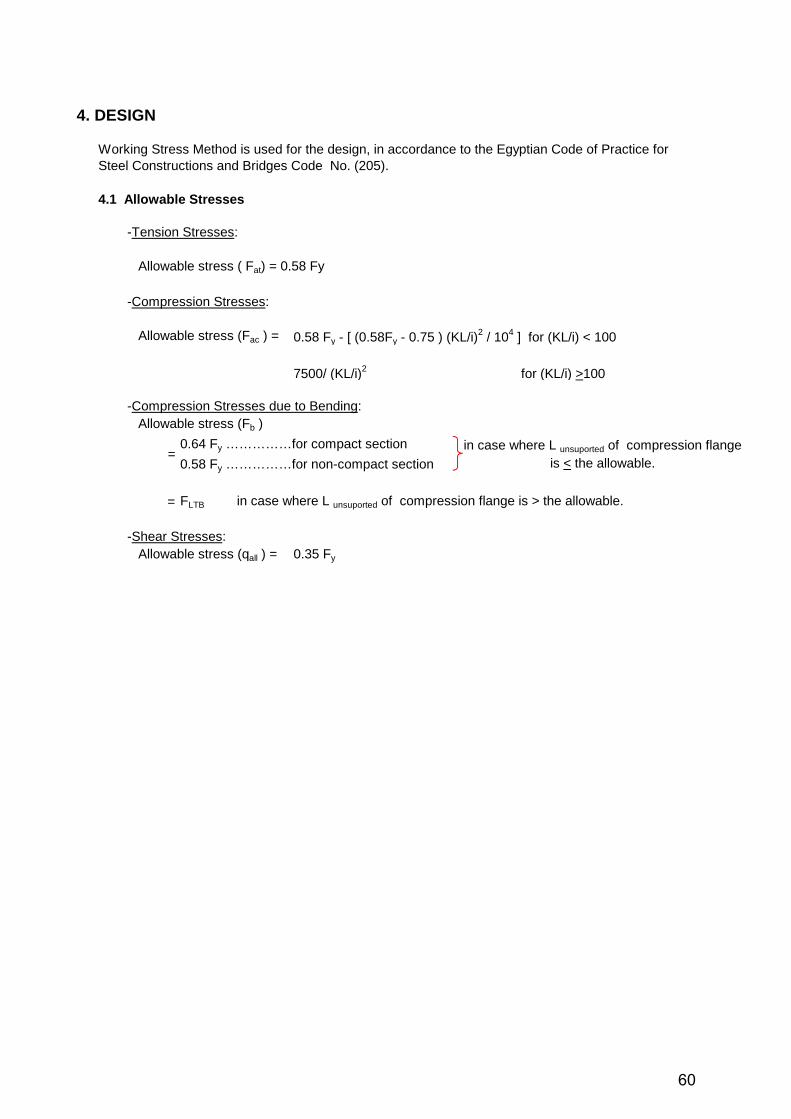
4. DESIGN
4.1 Allowable Stresses
-Tension Stresses:
Allowable stress ( Fat) = 0.58 Fy
-Compression Stresses:
Allowable stress (Fac ) = 0.58 Fy - [ (0.58Fy - 0.75 ) (KL/i)2 / 104 ] for (KL/i) < 100
7500/ (KL/i)2 for (KL/i) >100
-Compression Stresses due to Bending: Allowable stress (Fb )
0.64 Fy ……………for compact section
0.58 Fy ……………for non-compact section
= FLTB in case where L unsuported of compression flange is > the allowable.
-Shear Stresses: Allowable stress (qall ) = 0.35 Fy
Working Stress Method is used for the design, in accordance to the Egyptian Code of Practice for Steel Constructions and Bridges Code No. (205).
in case where L unsuported of compression flange is < the allowable.
=
60
Page 63
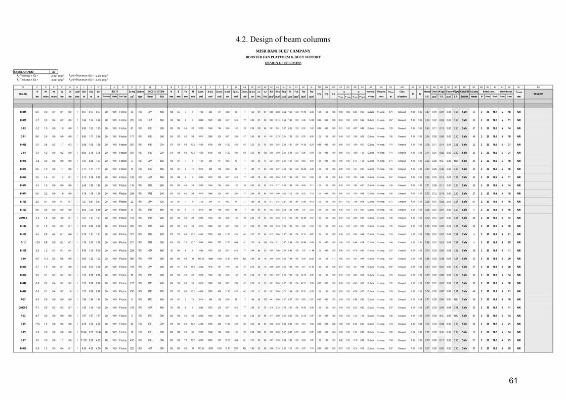
STEEL GRADE: 37 Fy (Thickness ≤ 40) = 2.40 t/cm2 Fy (40>Thickness≤100) = 2.15 t/cm2
Fu (Thickness ≤ 40) = 3.60 t/cm2 Fu (40>Thickness≤100) = 3.40 t/cm2
B C D E F G H I J K L M N O P Q R S T U V W X Y Z AA AB AC AD AE AF AG AH AI AJ AK AL AM AN AO AP AQ AR AS AT AU AV AW AX AY AZ BA BB BC BD BE BF BG BH BI BJ BK BL BM
N Mx My Qy Qx Load Lbx Lby Lu Zx req Section H B Tw Tf A act. Ix act. Zx act. ix act. Iy act. Zy act. iy act. x y fca fbcx fbcy Fc Fcb Fex Fey Max comp. Flange tip Lucom Class Normal Check Of % Safety SBS-weld
ton m.ton m.ton ton ton case m m m Diam-mm Grade Con.Type cm3 type Name Size mm mm mm mm cm2 cm4 cm3 cm cm4 cm3 cm Act. Act. t/cm2 t/cm2 t/cm2 t/cm2 t/cm2 t/cm2 t/cm2 web flange web flange in flange stress m of section S.R. t/cm2 S.R. t/cm2 S.R. Section Margin N D-mm Grade S-mm L-mm mm
B-011 0.0 0.0 0.1 0.1 0.2 1 0.97 0.97 0.97 20 10.9 Friction 36 RS UPN 120 120 55 7 9 17.00 364 61 4.62 43 11 1.59 21 61 0.00 0.03 0.63 1.39 1.39 17.19 2.03 1.00 1.00 1.00 1.00 1.00 0.86 0.04 Outside In comp. 0.71 Compact 1.00 1.00 0.47 0.01 0.01 0.03 0.03 Safe 53 2 20 10.9 5 10 N/R
B-021 -0.7 0.3 0.4 0.2 0.5 1 2.46 1.04 3.66 20 10.9 Friction 228 RS HEA 160 152 160 6 9 38.80 1670 220 6.57 616 77 3.98 37 26 0.02 0.14 0.54 1.30 1.39 5.35 10.93 0.85 0.85 1.00 0.59 1.00 -0.70 0.22 Outside In comp. 2.07 Compact 1.00 1.00 0.50 0.02 0.03 0.03 0.03 Safe 50 2 20 10.9 5 11 N/R
G-03 -0.2 1.0 0.0 1.0 0.0 1 9.90 1.93 1.93 20 10.9 Friction 81 RS IPE 200 200 100 5.6 8.5 28.50 1940 194 8.26 142 29 2.24 120 86 0.01 0.51 0.07 0.52 1.39 0.52 1.02 0.85 0.85 1.00 0.51 1.00 -0.97 0.88 Outside In comp. 1.29 Compact 1.00 1.00 0.43 0.11 0.13 0.00 0.00 Safe 57 2 20 10.9 5 14 N/R
G-01 0.6 2.4 0.0 0.0 0.0 1 9.90 1.17 3.66 20 10.9 Friction 171 RS IPE 240 240 120 6.2 9.8 39.10 3890 324 9.97 284 47 2.69 99 43 0.01 0.73 0.01 1.39 1.39 0.76 4.00 1.00 1.00 1.00 0.49 1.00 -1.05 0.99 Outside In comp. 1.55 Compact 1.00 1.00 0.54 0.00 0.00 0.00 0.00 Safe 46 2 20 10.9 5 18 N/R
B-026 -0.1 3.6 0.2 1.7 0.3 1 2.56 1.05 1.05 20 10.9 Friction 357 RS IPE 270 270 135 6.6 10.2 45.90 5790 429 11.20 420 62 3.02 23 35 0.00 0.84 0.32 1.31 1.54 14.36 6.20 0.85 0.85 1.00 0.50 1.00 -1.00 0.73 Outside In comp. 1.74 Compact 1.00 1.00 0.78 0.11 0.14 0.01 0.02 Safe 22 2 20 10.9 5 21 N/R
G-04 -0.1 4.2 0.0 0.2 0.0 1 9.90 3.76 3.76 20 10.9 Friction 301 RS IPE 270 270 135 6.6 10.2 45.90 5790 429 11.20 420 62 3.02 88 125 0.00 0.98 0.00 0.48 1.39 0.96 0.48 1.00 0.85 1.00 0.50 1.00 -0.99 1.00 Outside In comp. 1.74 Compact 1.00 1.00 0.71 0.01 0.02 0.00 0.00 Safe 29 2 20 10.9 5 21 N/R
B-076 -3.6 0.0 0.0 0.0 0.0 1 1.37 0.69 1.37 20 10.9 Friction 2 RS UPN 120 120 55 7 9 17.00 364 61 4.62 43 11 1.59 30 43 0.21 0.04 0.00 1.27 1.39 8.53 4.04 1.00 0.85 1.00 1.00 1.00 0.77 1.00 Outside In comp. 0.71 Compact 1.03 1.00 0.20 0.00 N/C 0.00 N/C Safe 80 2 20 10.9 5 10 N/R
B-075 0.0 1.0 0.0 1.7 0.0 1 1.11 1.11 1.11 20 10.9 Friction 73 RS IPE 160 160 82 5 7.4 20.10 869 109 6.58 68 17 1.84 17 60 0.00 0.87 0.06 1.39 1.39 26.59 2.08 1.00 1.00 1.00 0.50 1.00 -1.01 0.94 Outside In comp. 1.06 Compact 1.00 1.00 0.67 0.25 0.30 0.00 0.00 Safe 33 2 20 10.9 5 10 N/R
B-069 2.0 1.4 0.1 1.3 0.1 1 5.13 3.76 0.80 20 10.9 Friction 128 RS HEA 160 152 160 6 9 38.80 1670 220 6.57 616 77 3.98 78 95 0.05 0.65 0.07 1.39 1.54 1.23 0.84 1.00 1.00 1.00 0.45 1.00 -1.23 0.89 Outside In comp. 2.07 Compact 1.00 1.00 0.55 0.16 0.19 0.01 0.01 Safe 45 2 20 10.9 5 11 N/R
B-077 4.3 1.5 0.0 0.9 0.0 1 2.46 1.85 1.85 20 10.9 Friction 116 RS IPE 200 200 100 5.6 8.5 28.50 1940 194 8.26 142 29 2.24 30 82 0.15 0.77 0.06 1.39 1.39 8.46 1.11 1.00 1.00 1.00 0.38 1.00 -1.62 0.91 Outside In comp. 1.29 Compact 1.00 1.00 0.71 0.09 0.11 0.00 0.00 Safe 29 2 20 10.9 5 14 N/R
B-071 0.0 3.2 0.0 1.6 0.0 1 3.78 1.76 1.76 20 10.9 Friction 236 RS IPE 240 240 120 6.2 9.8 39.10 3890 324 9.97 284 47 2.69 38 65 0.00 1.00 0.02 1.12 1.39 5.22 1.75 1.00 0.85 1.00 0.50 1.00 -1.00 0.98 Outside In comp. 1.55 Compact 1.00 1.00 0.73 0.12 0.15 0.00 0.00 Safe 27 2 20 10.9 5 18 N/R
B-109 2.0 0.1 0.0 0.1 0.1 1 1.21 0.61 0.61 20 10.9 Friction 22 RS UPN 120 120 55 7 9 17.00 364 61 4.62 43 11 1.59 26 38 0.11 0.16 0.27 1.39 1.54 10.93 5.18 1.00 1.00 1.00 0.51 1.00 -1.05 0.16 Outside In comp. 0.71 Compact 1.00 1.00 0.39 0.01 0.02 0.01 0.01 Safe 61 2 20 10.9 5 10 N/R
B-100 0.6 0.6 0.0 0.0 0.0 1 5.50 1.00 5.50 20 10.9 Friction 44 RS IPE 160 160 82 5 7.4 20.10 869 109 6.58 68 17 1.84 84 54 0.03 0.55 0.02 1.39 0.58 1.07 2.54 1.00 1.00 1.00 0.46 1.00 -1.15 0.97 Outside In comp. 1.06 Compact 1.00 1.00 0.96 0.01 0.01 0.00 0.00 Safe 4 2 20 10.9 5 10 N/R
2071SA -1.2 1.8 0.0 3.0 0.1 1 1.21 1.21 1.21 20 10.9 Friction 144 RS IPE 200 200 100 5.6 8.5 28.50 1940 194 8.26 142 29 2.24 15 54 0.04 0.93 0.11 1.20 1.54 34.95 2.57 1.00 1.00 1.00 0.53 1.00 -0.90 0.90 Outside In comp. 1.29 Compact 1.00 1.02 0.72 0.31 0.37 0.00 0.01 Safe 28 2 20 10.9 5 14 N/R
B-112 1.8 1.6 0.2 0.3 0.1 1 5.50 2.90 2.90 20 10.9 Friction 205 RS IPE 240 240 120 6.2 9.8 39.10 3890 324 9.97 284 47 2.69 55 108 0.05 0.49 0.38 1.39 1.39 2.46 0.64 1.00 1.00 1.00 0.44 1.00 -1.25 0.54 Outside In comp. 1.55 Compact 1.00 1.00 0.66 0.03 0.03 0.01 0.01 Safe 34 2 20 10.9 5 18 N/R
B-107 5.4 2.8 0.4 0.1 0.6 1 2.76 1.21 1.21 20 10.9 Friction 377 RS IPE 270 270 135 6.6 10.2 45.90 5790 429 11.20 420 62 3.02 25 40 0.12 0.66 0.57 1.39 1.54 12.31 4.67 1.00 1.00 1.00 0.39 1.00 -1.54 0.49 Outside In comp. 1.74 Compact 1.00 1.00 0.96 0.01 0.01 0.03 0.04 Safe 4 2 20 10.9 5 21 N/R
G-12 -12.9 0.6 0.5 0.2 0.7 1 1.78 3.50 3.50 20 10.9 Friction 271 RS IPE 300 300 150 7.1 10.7 53.80 8360 557 12.50 604 81 3.35 14 104 0.24 0.11 0.57 0.69 1.39 36.99 0.69 1.00 0.85 1.00 1.00 1.00 0.44 0.38 Outside In comp. 1.94 Compact 1.01 1.31 0.96 0.01 0.01 0.03 0.04 Safe 4 2 20 10.9 5 25 N/R
B-103 -2.0 1.2 0.3 0.3 0.4 1 5.50 1.00 5.00 20 10.9 Friction 229 RS HEA 160 152 160 6 9 38.80 1670 220 6.57 616 77 3.98 84 25 0.05 0.56 0.36 0.94 1.39 1.07 11.88 1.00 0.85 1.05 0.56 1.00 -0.79 0.63 Outside In comp. 2.07 Compact 1.05 1.00 0.74 0.03 0.04 0.02 0.02 Safe 26 2 20 10.9 5 11 N/R
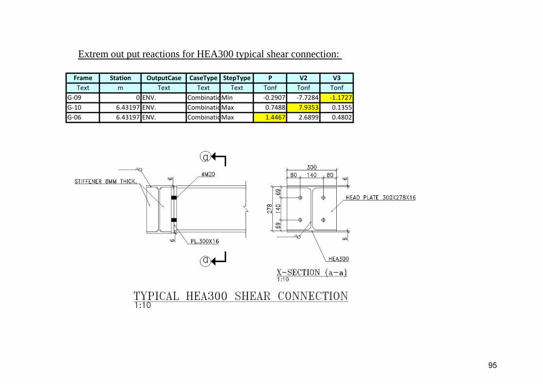
G-09 0.5 11.2 0.2 6.8 0.5 1 4.92 1.22 1.22 20 10.9 Friction 900 RS HEA 300 290 300 8.5 14 113.00 18260 1260 12.70 6310 421 7.49 39 16 0.00 0.89 0.05 1.39 1.54 5.00 28.27 1.00 1.00 1.11 0.50 1.00 -1.01 0.95 Outside In comp. 3.87 Compact 1.00 1.00 0.68 0.33 0.39 0.01 0.01 Safe 32 3 20 10.9 5 29 N/R
B-004 2.7 1.5 0.0 0.1 0.0 1 3.46 0.33 3.46 20 10.9 Friction 109 RS UPN 200 200 75 8.5 11.5 32.20 1910 191 7.70 148 27 2.14 45 15 0.08 0.80 0.00 1.39 1.39 3.71 31.54 1.00 1.00 1.45 0.57 1.00 -1.31 0.99 Outside In comp. 0.97 Compact 1.00 1.00 0.63 0.01 0.01 0.00 0.00 Safe 37 2 20 10.9 5 20 N/R
B-054 0.9 0.1 0.2 0.2 0.2 1 1.25 0.88 0.88 20 10.9 Friction 95 RS IPE 200 200 100 5.6 8.5 28.50 1940 194 8.26 142 29 2.24 15 39 0.03 0.07 0.60 1.39 1.54 32.75 4.92 1.00 1.00 1.00 0.22 1.00 -3.63 0.06 Outside In comp. 1.29 Compact 1.00 1.00 0.50 0.02 0.03 0.01 0.02 Safe 50 2 20 10.9 5 14 N/R
B-047 -0.6 0.2 0.4 0.2 0.2 1 1.25 0.88 0.88 20 10.9 Friction 217 RS IPE 240 240 120 6.2 9.8 39.10 3890 324 9.97 284 47 2.69 13 33 0.01 0.05 0.87 1.32 1.54 47.71 7.09 0.85 0.85 1.00 0.69 1.00 -0.45 0.07 Outside In comp. 1.55 Compact 1.00 1.00 0.67 0.01 0.01 0.01 0.01 Safe 33 2 20 10.9 5 18 N/R
B-084 -0.3 0.1 0.4 0.2 1.0 1 1.25 0.88 0.88 20 10.9 Friction 230 RS IPE 270 270 135 6.6 10.2 45.90 5790 429 11.20 420 62 3.02 11 29 0.01 0.03 0.71 1.34 1.54 60.21 8.93 1.00 1.00 1.00 0.63 1.00 -0.58 0.05 Outside In comp. 1.74 Compact 1.00 1.00 0.54 0.02 0.02 0.06 0.07 Safe 46 2 20 10.9 5 21 N/R
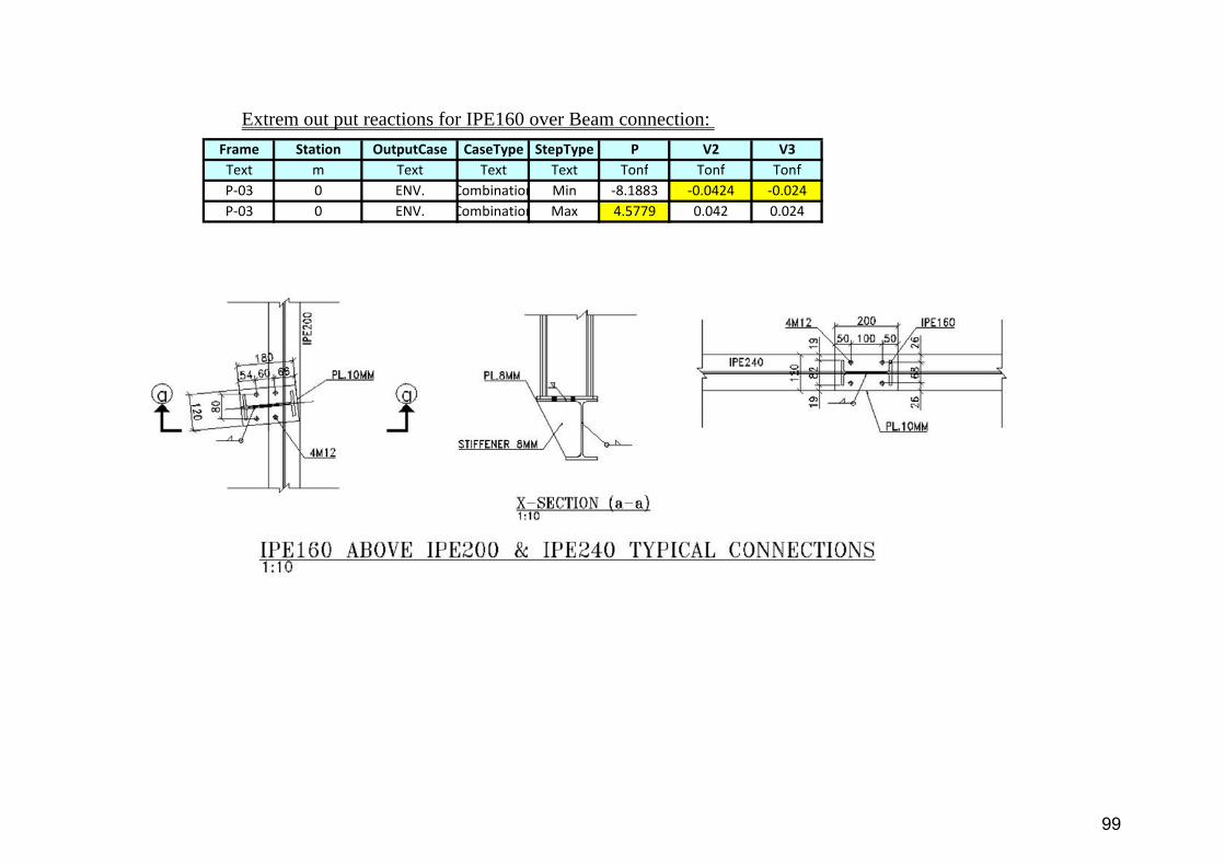
P-03 -8.2 0.0 0.0 0.0 0.0 1 1.94 1.94 1.94 20 10.9 Friction 6 RS IPE 160 160 82 5 7.4 20.10 869 109 6.58 68 17 1.84 29 105 0.41 0.00 0.07 0.67 1.39 8.63 0.67 0.85 0.85 1.75 1.00 1.00 0.99 0.85 Outside In comp. 1.06 Compact 1.00 2.14 0.71 0.00 0.00 0.00 N/C Safe 29 2 20 10.9 5 10 N/R
2030SG -7.1 0.5 0.2 0.3 0.7 1 1.40 1.40 1.40 20 10.9 Friction 129 RS HEA 160 152 160 6 9 38.80 1670 220 6.57 616 77 3.98 21 35 0.18 0.23 0.24 1.31 1.54 16.52 6.06 1.00 1.00 1.00 1.00 1.00 0.03 0.63 Outside In comp. 2.07 Compact 1.01 1.03 0.47 0.03 0.04 0.04 0.04 Safe 53 2 20 10.9 5 11 N/R
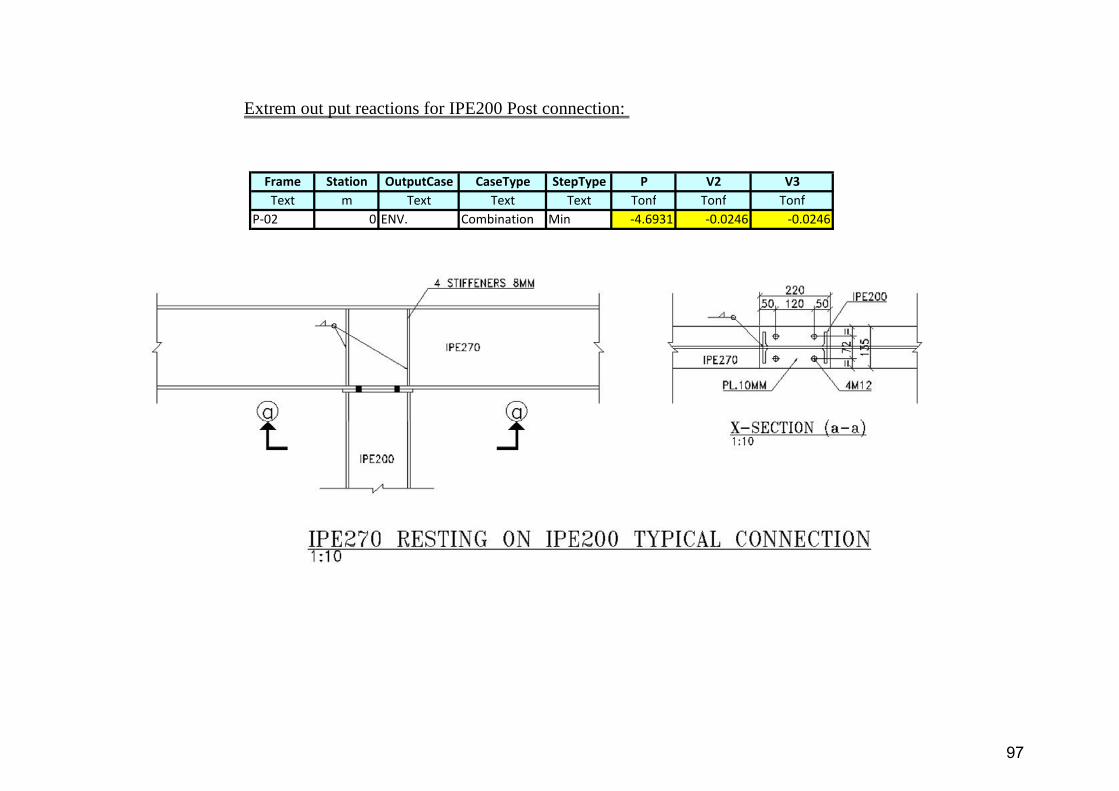
P-02 -4.7 0.0 0.0 0.0 0.0 1 1.97 1.97 1.97 20 10.9 Friction 0 RS IPE 200 200 100 5.6 8.5 28.50 1940 194 8.26 142 29 2.24 24 88 0.17 0.00 0.00 0.90 1.39 13.19 0.97 1.00 0.85 1.00 1.00 1.00 1.00 1.00 Outside In comp. 1.29 Compact 1.01 1.03 0.19 0.00 N/C 0.00 N/C Safe 81 2 20 10.9 5 14 N/R
C-05 -17.6 1.0 0.0 0.5 0.0 1 4.28 2.56 4.28 20 10.9 Friction 83 RS IPE 270 270 135 6.6 10.2 45.90 5790 429 11.20 420 62 3.02 38 85 0.38 0.23 0.04 0.93 1.39 5.14 1.04 0.85 0.85 1.28 1.00 1.00 0.32 0.94 Outside In comp. 1.74 Compact 1.00 1.34 0.62 0.03 0.04 0.00 0.00 Safe 38 2 20 10.9 5 21 N/R
C-09 -9.9 0.0 0.0 0.0 0.0 1 10.42 2.09 10.42 20 10.9 Friction 10 RS IPE 200 200 100 5.6 8.5 28.50 1940 194 8.26 142 29 2.24 126 93 0.35 0.00 0.07 0.47 0.35 0.47 0.87 0.85 0.85 1.04 1.00 1.00 1.00 0.83 Outside In comp. 1.29 Compact 3.28 1.42 0.81 0.00 N/C 0.00 0.00 Safe 19 2 20 10.9 5 14 N/R
G-07 3.9 5.5 0.0 1.7 0.0 1 11.20 2.80 4.23 20 10.9 Friction 410 RS IPE 300 300 150 7.1 10.7 53.80 8360 557 12.50 604 81 3.35 90 84 0.07 0.99 0.04 1.39 1.39 0.93 1.07 1.00 1.00 1.53 0.46 1.00 -1.19 0.96 Outside In comp. 1.94 Compact 1.00 1.00 0.79 0.09 0.11 0.00 0.00 Safe 21 2 20 10.9 5 25 N/R
B-066 -6.5 1.2 0.3 0.4 0.1 1 4.50 4.92 4.50 20 10.9 Friction 222 RS HEA 300 290 300 8.5 14 113.00 18260 1260 12.70 6310 421 7.49 35 66 0.06 0.10 0.06 1.11 1.39 5.97 1.74 0.85 0.85 1.00 0.87 1.00 -0.14 0.70 Outside In comp. 3.87 Compact 1.00 1.00 0.17 0.02 0.02 0.00 0.00 Safe 83 3 20 10.9 5 29 N/R
CROSS SECTIONCmx
MISR BANI SUEF CAMPANYBOOSTER FAN PLATFORM & DUCT SUPPORT
DESIGN OF SECTIONS
Mem. No.BOLTS
A2
Cmy CbCheck Of [qx]
REMARKSA1Check Of [qy] Bolted conn. Welded conn.
4.2. Design of beam columns
61
Page 64
m
70 mm 7 mm cm
cm
cm
< <
< Fc
ton >
ton
2
DateDate
-AM
Checked
-
Date
-HK
Approved
-
Design of Bolted Connection :
SectionSingle angle
70x7
t/cm2
-
10
Stress Ratio = 0.62
Check Stress Ratio :
0.234
0.375Allowable Stress : Fc =
Actual Stress : f ca =
SAFE
SAFE
Actual Stress :
Allowable Stress :
0.251
1.392
Check Stress Ratio :
t/cm2
Ft =
f ta =
30
AK
50
-
MISR BANI SUEF CAMPANY
Issued for Approval
BOOSTER FAN PLATFORM & DUCT SUPPORT
70x7
e =
1 -
67.1
0
q r =
Iv =
Rev. Descreption Design
F tr =
p
(S.R = 0.65)
tG.P
α = 0.8 tmin =
a =
1.50
Bolted
iu = 2.67
Single angle
Properties of Section :
Section :
Area =
M12
300
Lby =
9.40
Check Slenderness Ratio :
Design Calculation Sheet
Design of Angles Subjected to Axial Force According to ECP No.(205)
Kx =
1.97
109.5 200
ARESCOTEBBIN
cm417.6
Thickness of Gusset Plate =
Iu =
t =
cm4
asec
Project Tiltle :
Compression =
ST- 37Tension =
Departement :
2.201.80
t/cm2
1.50
Sheet No. :
1.37
iv =
Case of Loading :ton Grade of Steel : I
Member ID : HB-003
Lbx =
10 mm
ton
1.50 1.0m
Type of Connection :
Length =
Bolts :
m
109.5
7.17 cm2
λv =
Kg/mWeight =
A red =
Check as Tension Member :
cm2
1.0Ky =
7.38
SAFE
< Ft
1.61
3.78
Stress Ratio =
SAFE (S.R = 0.34)
0.18
0.4 Fy = 0.96
6.43
At =
ton
t/cm2
SAFE
2M12(8.8)
e
25
Bolts
Check of Shear Rapture :
Shear Strength :
No. of Bolts = 1.31
Bearing Strength :
R sh = q b x A s x n =
Bolts
R b = F b x d x t min = 2.42
1.68
cm2
cm2
2.2 tonqr x Ash + Ftr x At =
0.725 Fy = 1.74
x
mm7
Check as Compression Member :
Grade of Bolts : 8.8 Ash =Bolts : M12
t/cm2
t/cm2
Check Slenderness Ratio :
λv =
e p p e
x
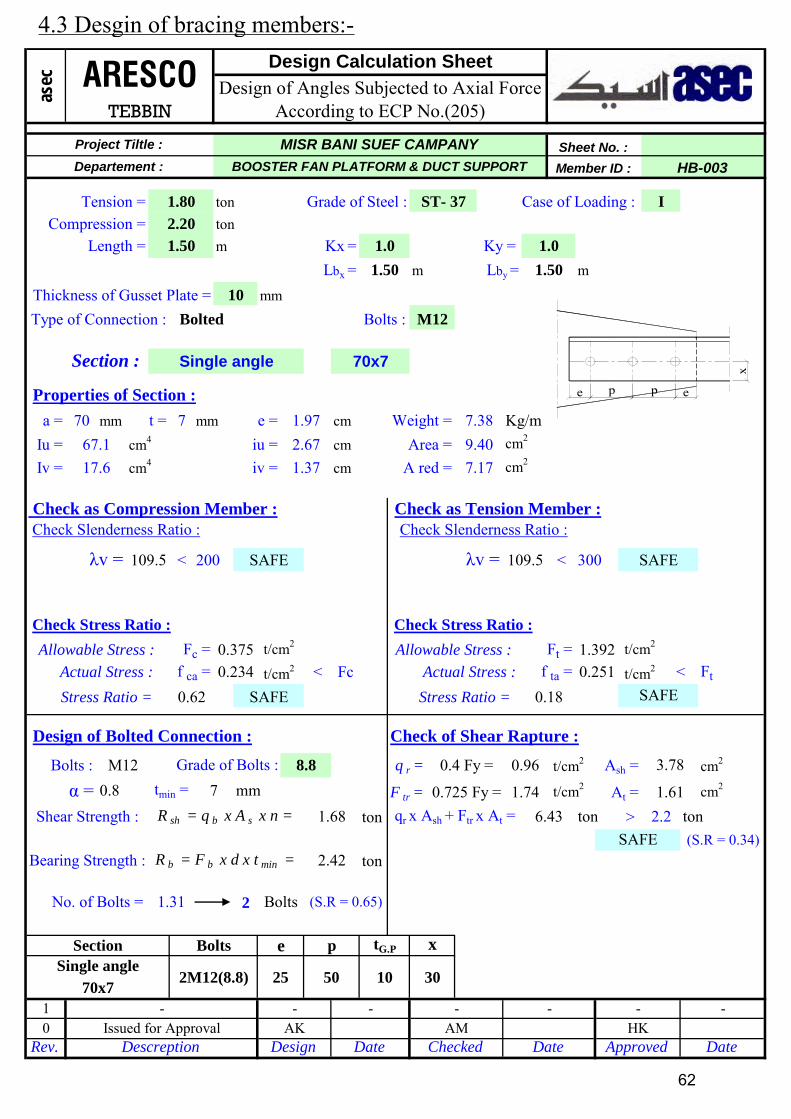
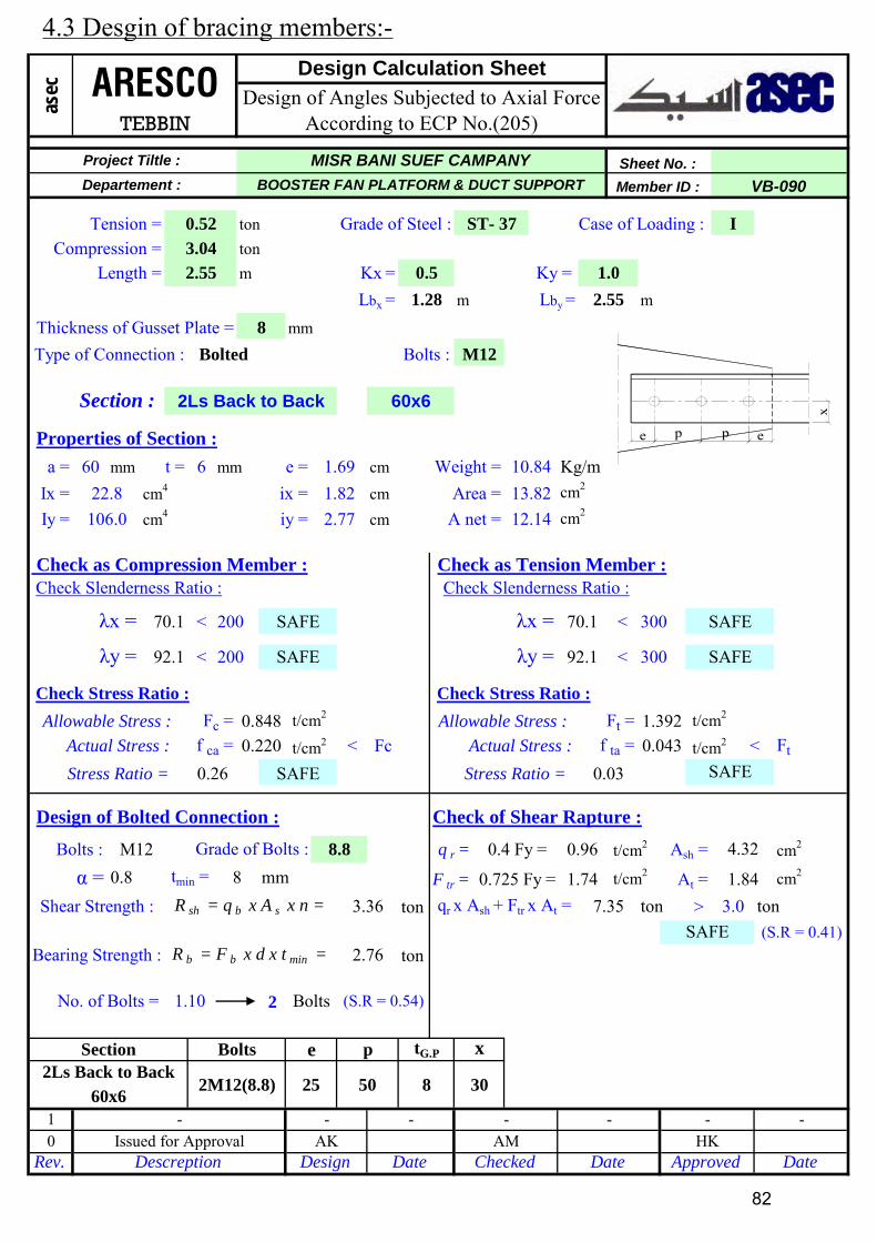
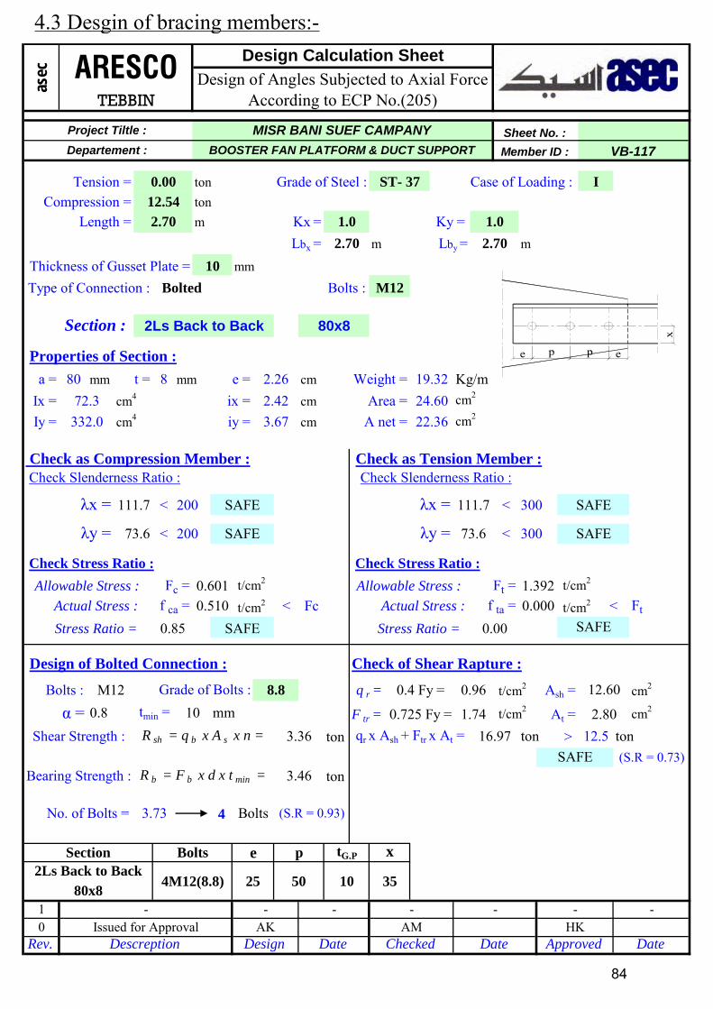
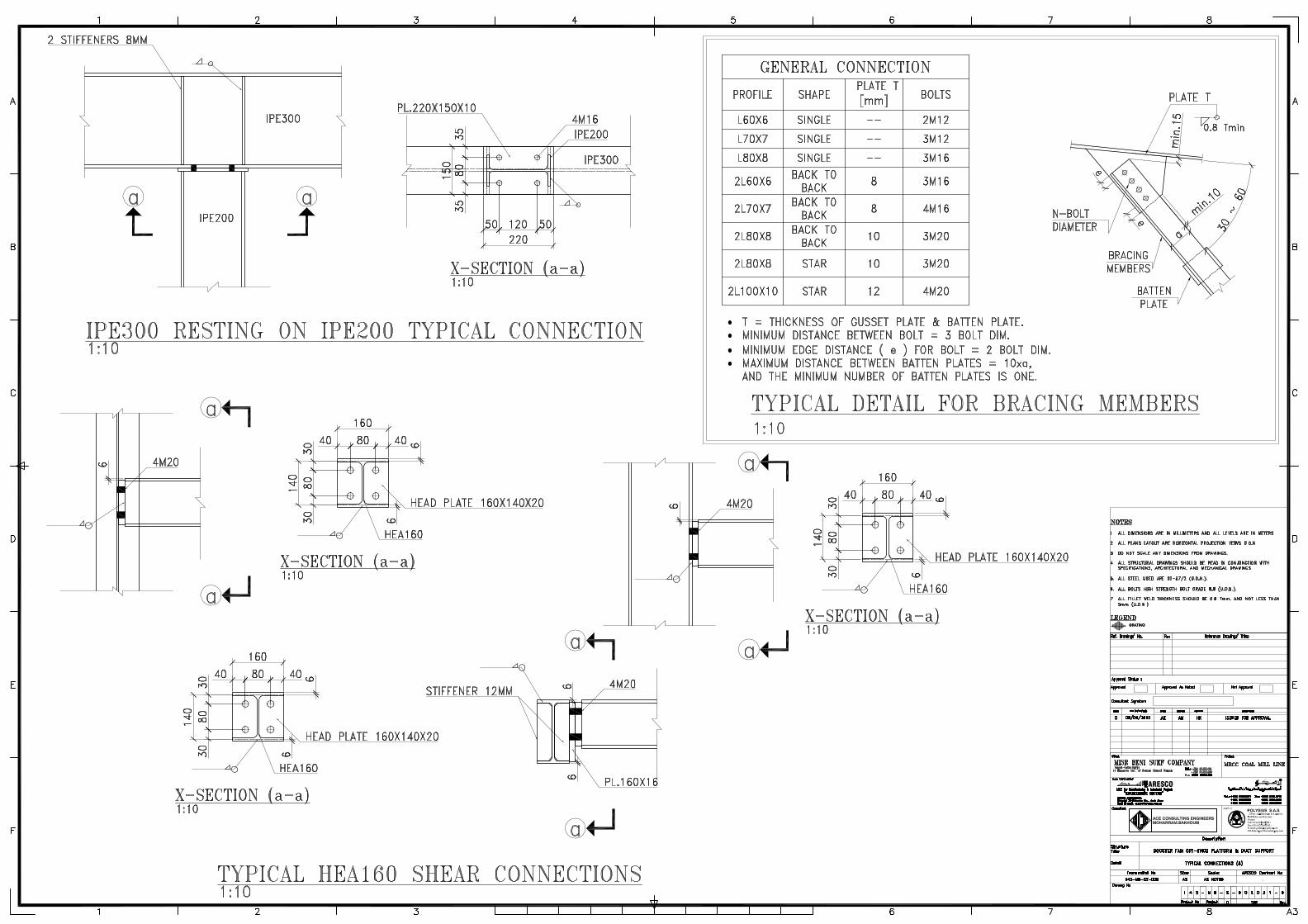
4.3 Desgin of bracing members:-
62
Page 65
m
60 mm 6 mm cm
cm
cm
< <
< Fc
ton >
ton
2
Check as Compression Member :
Grade of Bolts : 8.8 Ash =Bolts : M12
t/cm2
t/cm2
Check Slenderness Ratio :
λv =
qr x Ash + Ftr x At =
0.725 Fy = 1.74
x
mm6
2.07
1.68
cm2
cm2
0.1 tonShear Strength :
No. of Bolts = 0.03
Bearing Strength :
R sh = q b x A s x n =
Bolts
R b = F b x d x t min =
SAFE
2M12(8.8)
e
25
Bolts
Check of Shear Rapture :
Stress Ratio =
SAFE (S.R = 0)
0.00
0.4 Fy = 0.96
5.51
At =
ton
t/cm2
< Ft
1.38
3.24
SAFE
A red =
Check as Tension Member :
cm2
1.0Ky =
5.42
Type of Connection :
Length =
Bolts :
m
120.5
5.12 cm2
λv =
Kg/mWeight =
Lbx =
10 mm
ton
1.41 1.0m
ton Grade of Steel : I
Member ID : HB-039
t/cm2
1.41
Sheet No. :
1.17
iv =
Case of Loading :
asec
Project Tiltle :
Compression =
ST- 37Tension =
Departement :
0.060.03
120.5 200
ARESCOTEBBIN
cm49.4
Thickness of Gusset Plate =
Iu =
t =
cm4
300
Lby =
6.91
Check Slenderness Ratio :
Design Calculation Sheet
Design of Angles Subjected to Axial Force According to ECP No.(205)
Kx =
1.69a =
1.41
Bolted
iu = 2.29
Single angle
Properties of Section :
Section :
Area =
M12
Rev. Descreption Design
F tr =
p
(S.R = 0.01)
tG.P
α = 0.8 tmin =
1 -
36.1
0
q r =
Iv =
30
AK
50
-
MISR BANI SUEF CAMPANY
Issued for Approval
BOOSTER FAN PLATFORM & DUCT SUPPORT
60x6
e =
SAFE
Actual Stress :
Allowable Stress :
0.005
1.392
Check Stress Ratio :
t/cm2
Ft =
f ta =
Stress Ratio = 0.03
Check Stress Ratio :
0.008
0.310Allowable Stress : Fc =
Actual Stress : f ca =
SAFE
Approved
-
Design of Bolted Connection :
SectionSingle angle
60x6
t/cm2
-
10
DateDate
-AM
Checked
-
Date
-HK
e p p e
x
4.3 Desgin of bracing members:-
63
Page 66
m
60 mm 6 mm cm
cm
cm
< <
< Fc
ton >
ton
2
DateDate
-AM
Checked
-
Date
-HK
Approved
-
Design of Bolted Connection :
SectionSingle angle
60x6
t/cm2
-
10
Stress Ratio = 0.36
Check Stress Ratio :
0.191
0.524Allowable Stress : Fc =
Actual Stress : f ca =
SAFE
SAFE
Actual Stress :
Allowable Stress :
0.045
1.392
Check Stress Ratio :
t/cm2
Ft =
f ta =
30
AK
50
-
MISR BANI SUEF CAMPANY
Issued for Approval
BOOSTER FAN PLATFORM & DUCT SUPPORT
60x6
e =
1 -
36.1
0
q r =
Iv =
Rev. Descreption Design
F tr =
p
(S.R = 0.39)
tG.P
α = 0.8 tmin =
a =
1.05
Bolted
iu = 2.29
Single angle
Properties of Section :
Section :
Area =
M12
300
Lby =
6.91
Check Slenderness Ratio :
Design Calculation Sheet
Design of Angles Subjected to Axial Force According to ECP No.(205)
Kx =
1.69
89.8 200
ARESCOTEBBIN
cm49.4
Thickness of Gusset Plate =
Iu =
t =
cm4
asec
Project Tiltle :
Compression =
ST- 37Tension =
Departement :
1.320.23
t/cm2
1.05
Sheet No. :
1.17
iv =
Case of Loading :ton Grade of Steel : I
Member ID : HB-047
Lbx =
10 mm
ton
1.05 1.0m
Type of Connection :
Length =
Bolts :
m
89.8
5.12 cm2
λv =
Kg/mWeight =
A red =
Check as Tension Member :
cm2
1.0Ky =
5.42
SAFE
< Ft
1.38
3.24
Stress Ratio =
SAFE (S.R = 0.23)
0.03
0.4 Fy = 0.96
5.51
At =
ton
t/cm2
SAFE
2M12(8.8)
e
25
Bolts
Check of Shear Rapture :
Shear Strength :
No. of Bolts = 0.79
Bearing Strength :
R sh = q b x A s x n =
Bolts
R b = F b x d x t min = 2.07
1.68
cm2
cm2
1.3 tonqr x Ash + Ftr x At =
0.725 Fy = 1.74
x
mm6
Check as Compression Member :
Grade of Bolts : 8.8 Ash =Bolts : M12
t/cm2
t/cm2
Check Slenderness Ratio :
λv =
e p p e
x
4.3 Desgin of bracing members:-
64
Page 67
m
70 mm 7 mm cm
cm
cm
< <
< Fc
ton >
ton
2
Check as Compression Member :
Grade of Bolts : 8.8 Ash =Bolts : M12
t/cm2
t/cm2
Check Slenderness Ratio :
λv =
qr x Ash + Ftr x At =
0.725 Fy = 1.74
x
mm7
2.42
1.68
cm2
cm2
1.8 tonShear Strength :
No. of Bolts = 1.07
Bearing Strength :
R sh = q b x A s x n =
Bolts
R b = F b x d x t min =
SAFE
2M12(8.8)
e
25
Bolts
Check of Shear Rapture :
Stress Ratio =
SAFE (S.R = 0.27)
0.02
0.4 Fy = 0.96
6.43
At =
ton
t/cm2
< Ft
1.61
3.78
SAFE
A red =
Check as Tension Member :
cm2
1.0Ky =
7.38
Type of Connection :
Length =
Bolts :
m
116.4
7.17 cm2
λv =
Kg/mWeight =
Lbx =
10 mm
ton
1.59 1.0m
ton Grade of Steel : I
Member ID : HB-058
t/cm2
1.59
Sheet No. :
1.37
iv =
Case of Loading :
asec
Project Tiltle :
Compression =
ST- 37Tension =
Departement :
1.800.23
116.4 200
ARESCOTEBBIN
cm417.6
Thickness of Gusset Plate =
Iu =
t =
cm4
300
Lby =
9.40
Check Slenderness Ratio :
Design Calculation Sheet
Design of Angles Subjected to Axial Force According to ECP No.(205)
Kx =
1.97a =
1.59
Bolted
iu = 2.67
Single angle
Properties of Section :
Section :
Area =
M12
Rev. Descreption Design
F tr =
p
(S.R = 0.53)
tG.P
α = 0.8 tmin =
1 -
67.1
0
q r =
Iv =
30
AK
50
-
MISR BANI SUEF CAMPANY
Issued for Approval
BOOSTER FAN PLATFORM & DUCT SUPPORT
70x7
e =
SAFE
Actual Stress :
Allowable Stress :
0.032
1.392
Check Stress Ratio :
t/cm2
Ft =
f ta =
Stress Ratio = 0.58
Check Stress Ratio :
0.191
0.332Allowable Stress : Fc =
Actual Stress : f ca =
SAFE
Approved
-
Design of Bolted Connection :
SectionSingle angle
70x7
t/cm2
-
10
DateDate
-AM
Checked
-
Date
-HK
e p p e
x
4.3 Desgin of bracing members:-
65
Page 68
m
80 mm 8 mm cm
cm
cm
< <
< Fc
ton >
ton
2
DateDate
-AM
Checked
-
Date
-HK
Approved
-
Design of Bolted Connection :
SectionSingle angle
80x8
t/cm2
-
10
Stress Ratio = 0.61
Check Stress Ratio :
0.203
0.334Allowable Stress : Fc =
Actual Stress : f ca =
SAFE
SAFE
Actual Stress :
Allowable Stress :
0.017
1.392
Check Stress Ratio :
t/cm2
Ft =
f ta =
35
AK
50
-
MISR BANI SUEF CAMPANY
Issued for Approval
BOOSTER FAN PLATFORM & DUCT SUPPORT
80x8
e =
1 -
115.0
0
q r =
Iv =
Rev. Descreption Design
F tr =
p
(S.R = 0.74)
tG.P
α = 0.8 tmin =
a =
1.80
Bolted
iu = 3.06
Single angle
Properties of Section :
Section :
Area =
M12
300
Lby =
12.30
Check Slenderness Ratio :
Design Calculation Sheet
Design of Angles Subjected to Axial Force According to ECP No.(205)
Kx =
2.26
116.1 200
ARESCOTEBBIN
cm429.6
Thickness of Gusset Plate =
Iu =
t =
cm4
asec
Project Tiltle :
Compression =
ST- 37Tension =
Departement :
2.500.16
t/cm2
1.80
Sheet No. :
1.55
iv =
Case of Loading :ton Grade of Steel : I
Member ID : HB-120
Lbx =
10 mm
ton
1.80 1.0m
Type of Connection :
Length =
Bolts :
m
116.1
9.58 cm2
λv =
Kg/mWeight =
A red =
Check as Tension Member :
cm2
1.0Ky =
9.66
SAFE
< Ft
2.24
4.32
Stress Ratio =
SAFE (S.R = 0.31)
0.01
0.4 Fy = 0.96
8.04
At =
ton
t/cm2
SAFE
2M12(8.8)
e
25
Bolts
Check of Shear Rapture :
Shear Strength :
No. of Bolts = 1.49
Bearing Strength :
R sh = q b x A s x n =
Bolts
R b = F b x d x t min = 2.76
1.68
cm2
cm2
2.5 tonqr x Ash + Ftr x At =
0.725 Fy = 1.74
x
mm8
Check as Compression Member :
Grade of Bolts : 8.8 Ash =Bolts : M12
t/cm2
t/cm2
Check Slenderness Ratio :
λv =
e p p e
x
4.3 Desgin of bracing members:-
66
Page 69
m
60 mm 6 mm cm
cm
cm
< <
< Fc
ton >
ton
2
Check as Compression Member :
Grade of Bolts : 8.8 Ash =Bolts : M12
t/cm2
t/cm2
Check Slenderness Ratio :
λv =
qr x Ash + Ftr x At =
0.725 Fy = 1.74
x
mm6
2.07
1.68
cm2
cm2
2.6 tonShear Strength :
No. of Bolts = 1.53
Bearing Strength :
R sh = q b x A s x n =
Bolts
R b = F b x d x t min =
SAFE
2M12(8.8)
e
25
Bolts
Check of Shear Rapture :
Stress Ratio =
SAFE (S.R = 0.46)
0.07
0.4 Fy = 0.96
5.51
At =
ton
t/cm2
< Ft
1.38
3.24
SAFE
A red =
Check as Tension Member :
cm2
1.0Ky =
5.42
Type of Connection :
Length =
Bolts :
m
105.1
5.12 cm2
λv =
Kg/mWeight =
Lbx =
10 mm
ton
1.23 1.0m
ton Grade of Steel : I
Member ID : HB-147
t/cm2
1.23
Sheet No. :
1.17
iv =
Case of Loading :
asec
Project Tiltle :
Compression =
ST- 37Tension =
Departement :
2.570.47
105.1 200
ARESCOTEBBIN
cm49.4
Thickness of Gusset Plate =
Iu =
t =
cm4
300
Lby =
6.91
Check Slenderness Ratio :
Design Calculation Sheet
Design of Angles Subjected to Axial Force According to ECP No.(205)
Kx =
1.69a =
1.23
Bolted
iu = 2.29
Single angle
Properties of Section :
Section :
Area =
M12
Rev. Descreption Design
F tr =
p
(S.R = 0.76)
tG.P
α = 0.8 tmin =
1 -
36.1
0
q r =
Iv =
30
AK
50
-
MISR BANI SUEF CAMPANY
Issued for Approval
BOOSTER FAN PLATFORM & DUCT SUPPORT
60x6
e =
SAFE
Actual Stress :
Allowable Stress :
0.092
1.392
Check Stress Ratio :
t/cm2
Ft =
f ta =
Stress Ratio = 0.91
Check Stress Ratio :
0.371
0.407Allowable Stress : Fc =
Actual Stress : f ca =
SAFE
Approved
-
Design of Bolted Connection :
SectionSingle angle
60x6
t/cm2
-
10
DateDate
-AM
Checked
-
Date
-HK
e p p e
x
4.3 Desgin of bracing members:-
67
Page 70
m
100 mm 10 mm cm
cm
cm
< <
< Fc
ton >
ton
2
Check as Compression Member :
Grade of Bolts : 8.8 Ash =Bolts : M12
t/cm2
t/cm2
Check Slenderness Ratio :
λu =
qr x Ash + Ftr x At =
0.725 Fy = 1.74
x
mm10
3.46
1.68
cm2
cm2
0.2 tonShear Strength :
No. of Bolts = 0.09
Bearing Strength :
R sh = q b x A s x n =
Bolts
R b = F b x d x t min =
SAFE
2M12(8.8)
e
25
Bolts
Check of Shear Rapture :
Stress Ratio =
SAFE (S.R = 0.01)
0.00
0.4 Fy = 0.96
11.80
At =
ton
t/cm2
< Ft
3.80
5.40
SAFE
A net =
Check as Tension Member :
cm2
1.0Ky =
30.2
Type of Connection :
Length =
Bolts :
m
183.2
35.60 cm2
λu =
Kg/mWeight =
Lbx =
10 mm
ton
7.00 1.0m
ton Grade of Steel : I
Member ID : MRHB
t/cm2
7.00
Sheet No. :
1.95
iv =
Case of Loading :
asec
Project Tiltle :
Compression =
ST- 37Tension =
Departement :
0.120.16
183.2 200
ARESCOTEBBIN
cm473.3
Thickness of Gusset Plate =
Iu =
t =
cm4
300
Lby =
38.40
Check Slenderness Ratio :
Design Calculation Sheet
Design of Angles Subjected to Axial Force According to ECP No.(205)
Kx =
2.82a =
7.00
Bolted
iu = 3.82
2Ls Star-Shaped
Properties of Section :
Section :
Area =
M12
Rev. Descreption Design
F tr =
p
(S.R = 0.04)
tG.P
α = 0.8 tmin =
1 -
280.0
0
q r =
Iv =
45
AK
50
-
MISR BANI SUEF CAMPANY
Issued for Approval
BOOSTER FAN PLATFORM & DUCT SUPPORT
100x10
e =
SAFE
Actual Stress :
Allowable Stress :
0.004
1.392
Check Stress Ratio :
t/cm2
Ft =
f ta =
Stress Ratio = 0.01
Check Stress Ratio :
0.003
0.223Allowable Stress : Fc =
Actual Stress : f ca =
SAFE
Approved
-
Design of Bolted Connection :
Section2Ls Star-Shaped
100x10
t/cm2
-
10
DateDate
-AM
Checked
-
Date
-HK
e p p e
x
4.3 Desgin of bracing members:-
68
Page 71
m
60 mm 6 mm cm
cm
cm
< <
< <
< Fc
ton >
ton
2
DateDate
-AM
Checked
-
Date
-HK
Approved
-
Design of Bolted Connection :
Section2Ls Back to Back
60x6
t/cm2
-
8
Stress Ratio = 0.51
Check Stress Ratio :
0.178
0.351Allowable Stress : Fc =
Actual Stress : f ca =
SAFE
SAFE
Actual Stress :
Allowable Stress :
0.000
1.392
Check Stress Ratio :
t/cm2
Ft =
96.1
f ta =
30
AK
50
-
MISR BANI SUEF CAMPANY
Issued for Approval
BOOSTER FAN PLATFORM & DUCT SUPPORT
60x6
e =
1 -
22.8
96.1
0
λy =
q r =
Iy =
λy = 200
Rev. Descreption Design
F tr =
p
(S.R = 0.44)
tG.P
α = 0.8 tmin =
a =
2.66
Bolted
ix = 1.82
2Ls Back to Back
Properties of Section :
Section :
Area =
M12
300
300
Lby =
13.82
Check Slenderness Ratio :
Design Calculation Sheet
Design of Angles Subjected to Axial Force According to ECP No.(205)
Kx =
1.69
146.2 200
ARESCOTEBBIN
cm4106.0
Thickness of Gusset Plate =
Ix =
t =
cm4
asec
Project Tiltle :
Compression =
ST- 37Tension =
Departement :
2.460.00
t/cm2
2.66
Sheet No. :
2.77
SAFE
iy =
Case of Loading :ton Grade of Steel : I
Member ID : NB-03
Lbx =
8 mm
ton
2.66 1.0m
Type of Connection :
Length =
Bolts :
m
146.2
12.14 cm2
λx =
Kg/mWeight =
A net =
Check as Tension Member :
cm2
1.0Ky =
10.84
SAFE
SAFE
< Ft
1.84
4.32
Stress Ratio =
SAFE (S.R = 0.33)
0.00
0.4 Fy = 0.96
7.35
At =
ton
t/cm2
SAFE
2M12(8.8)
e
25
Bolts
Check of Shear Rapture :
Shear Strength :
No. of Bolts = 0.89
Bearing Strength :
R sh = q b x A s x n =
Bolts
R b = F b x d x t min = 2.76
3.36
cm2
cm2
2.5 tonqr x Ash + Ftr x At =
0.725 Fy = 1.74
x
mm8
Check as Compression Member :
Grade of Bolts : 8.8 Ash =Bolts : M12
t/cm2
t/cm2
Check Slenderness Ratio :
λx =
e p p e
x
4.3 Desgin of bracing members:-
69
Page 72
m
70 mm 7 mm cm
cm
cm
< <
< <
< Fc
ton >
ton
4
Check as Compression Member :
Grade of Bolts : 8.8 Ash =Bolts : M12
t/cm2
t/cm2
Check Slenderness Ratio :
λx =
qr x Ash + Ftr x At =
0.725 Fy = 1.74
x
mm8
2.76
3.36
cm2
cm2
8.4 tonShear Strength :
No. of Bolts = 3.04
Bearing Strength :
R sh = q b x A s x n =
Bolts
R b = F b x d x t min =
SAFE
4M12(8.8)
e
25
Bolts
Check of Shear Rapture :
Stress Ratio =
SAFE (S.R = 0.65)
0.00
0.4 Fy = 0.96
12.88
At =
ton
t/cm2
< Ft
1.84
10.08
SAFE
SAFE
A net =
Check as Tension Member :
cm2
1.0Ky =
14.76
Type of Connection :
Length =
Bolts :
m
81.8
16.84 cm2
λx =
Kg/mWeight =
Lbx =
8 mm
ton
3.47 0.5m
ton Grade of Steel : I
Member ID : NB-05
t/cm2
3.47
Sheet No. :
3.18
SAFE
iy =
Case of Loading :
asec
Project Tiltle :
Compression =
ST- 37Tension =
Departement :
8.400.00
81.8 200
ARESCOTEBBIN
cm4190.4
Thickness of Gusset Plate =
Ix =
t =
cm4
300
300
Lby =
18.80
Check Slenderness Ratio :
Design Calculation Sheet
Design of Angles Subjected to Axial Force According to ECP No.(205)
Kx =
1.97a =
1.74
Bolted
ix = 2.12
2Ls Back to Back
Properties of Section :
Section :
Area =
M12
Rev. Descreption Design
F tr =
p
(S.R = 0.75)
tG.P
α = 0.8 tmin =
1 -
42.4
109.0
0
λy =
q r =
Iy =
λy = 200
30
AK
50
-
MISR BANI SUEF CAMPANY
Issued for Approval
BOOSTER FAN PLATFORM & DUCT SUPPORT
70x7
e =
SAFE
Actual Stress :
Allowable Stress :
0.000
1.392
Check Stress Ratio :
t/cm2
Ft =
109.0
f ta =
Stress Ratio = 0.71
Check Stress Ratio :
0.447
0.631Allowable Stress : Fc =
Actual Stress : f ca =
SAFE
Approved
-
Design of Bolted Connection :
Section2Ls Back to Back
70x7
t/cm2
-
8
DateDate
-AM
Checked
-
Date
-HK
e p p e
x
4.3 Desgin of bracing members:-
70
Page 73
m
60 mm 6 mm cm
cm
cm
< <
< <
< Fc
ton >
ton
3
Check as Compression Member :
Grade of Bolts : 8.8 Ash =Bolts : M12
t/cm2
t/cm2
Check Slenderness Ratio :
λx =
qr x Ash + Ftr x At =
0.725 Fy = 1.74
x
mm8
2.76
3.36
cm2
cm2
6.4 tonShear Strength :
No. of Bolts = 2.31
Bearing Strength :
R sh = q b x A s x n =
Bolts
R b = F b x d x t min =
SAFE
3M12(8.8)
e
25
Bolts
Check of Shear Rapture :
Stress Ratio =
SAFE (S.R = 0.63)
0.38
0.4 Fy = 0.96
10.11
At =
ton
t/cm2
< Ft
1.84
7.20
SAFE
SAFE
A net =
Check as Tension Member :
cm2
1.0Ky =
10.84
Type of Connection :
Length =
Bolts :
m
65.2
12.14 cm2
λx =
Kg/mWeight =
Lbx =
8 mm
ton
2.37 0.5m
ton Grade of Steel : I
Member ID : SGBR-08
t/cm2
2.37
Sheet No. :
2.77
SAFE
iy =
Case of Loading :
asec
Project Tiltle :
Compression =
ST- 37Tension =
Departement :
5.606.40
65.2 200
ARESCOTEBBIN
cm4106.0
Thickness of Gusset Plate =
Ix =
t =
cm4
300
300
Lby =
13.82
Check Slenderness Ratio :
Design Calculation Sheet
Design of Angles Subjected to Axial Force According to ECP No.(205)
Kx =
1.69a =
1.19
Bolted
ix = 1.82
2Ls Back to Back
Properties of Section :
Section :
Area =
M12
Rev. Descreption Design
F tr =
p
(S.R = 0.77)
tG.P
α = 0.8 tmin =
1 -
22.8
85.7
0
λy =
q r =
Iy =
λy = 200
30
AK
50
-
MISR BANI SUEF CAMPANY
Issued for Approval
BOOSTER FAN PLATFORM & DUCT SUPPORT
60x6
e =
SAFE
Actual Stress :
Allowable Stress :
0.527
1.392
Check Stress Ratio :
t/cm2
Ft =
85.7
f ta =
Stress Ratio = 0.44
Check Stress Ratio :
0.405
0.920Allowable Stress : Fc =
Actual Stress : f ca =
SAFE
Approved
-
Design of Bolted Connection :
Section2Ls Back to Back
60x6
t/cm2
-
8
DateDate
-AM
Checked
-
Date
-HK
e p p e
x
4.3 Desgin of bracing members:-
71
Page 74
m
60 mm 6 mm cm
cm
cm
< <
< <
< Fc
ton >
ton
3
DateDate
-AM
Checked
-
Date
-HK
Approved
-
Design of Bolted Connection :
Section2Ls Back to Back
60x6
t/cm2
-
8
Stress Ratio = 0.50
Check Stress Ratio :
0.504
1.012Allowable Stress : Fc =
Actual Stress : f ca =
SAFE
SAFE
Actual Stress :
Allowable Stress :
0.387
1.392
Check Stress Ratio :
t/cm2
Ft =
50.6
f ta =
30
AK
50
-
MISR BANI SUEF CAMPANY
Issued for Approval
BOOSTER FAN PLATFORM & DUCT SUPPORT
60x6
e =
1 -
22.8
50.6
0
λy =
q r =
Iy =
λy = 200
Rev. Descreption Design
F tr =
p
(S.R = 0.84)
tG.P
α = 0.8 tmin =
a =
1.40
Bolted
ix = 1.82
2Ls Back to Back
Properties of Section :
Section :
Area =
M12
300
300
Lby =
13.82
Check Slenderness Ratio :
Design Calculation Sheet
Design of Angles Subjected to Axial Force According to ECP No.(205)
Kx =
1.69
76.9 200
ARESCOTEBBIN
cm4106.0
Thickness of Gusset Plate =
Ix =
t =
cm4
asec
Project Tiltle :
Compression =
ST- 37Tension =
Departement :
6.974.70
t/cm2
1.40
Sheet No. :
2.77
SAFE
iy =
Case of Loading :ton Grade of Steel : I
Member ID : SGBR-14
Lbx =
8 mm
ton
1.40 1.0m
Type of Connection :
Length =
Bolts :
m
76.9
12.14 cm2
λx =
Kg/mWeight =
A net =
Check as Tension Member :
cm2
1.0Ky =
10.84
SAFE
SAFE
< Ft
1.84
7.20
Stress Ratio =
SAFE (S.R = 0.68)
0.28
0.4 Fy = 0.96
10.11
At =
ton
t/cm2
SAFE
3M12(8.8)
e
25
Bolts
Check of Shear Rapture :
Shear Strength :
No. of Bolts = 2.52
Bearing Strength :
R sh = q b x A s x n =
Bolts
R b = F b x d x t min = 2.76
3.36
cm2
cm2
7.0 tonqr x Ash + Ftr x At =
0.725 Fy = 1.74
x
mm8
Check as Compression Member :
Grade of Bolts : 8.8 Ash =Bolts : M12
t/cm2
t/cm2
Check Slenderness Ratio :
λx =
e p p e
x
4.3 Desgin of bracing members:-
72
Page 75
m
80 mm 8 mm cm
cm
cm
< <
< Fc
ton >
ton
2
Check as Compression Member :
Grade of Bolts : 8.8 Ash =Bolts : M12
t/cm2
t/cm2
Check Slenderness Ratio :
λu =
qr x Ash + Ftr x At =
0.725 Fy = 1.74
x
mm8
2.76
1.68
cm2
cm2
0.8 tonShear Strength :
No. of Bolts = 0.49
Bearing Strength :
R sh = q b x A s x n =
Bolts
R b = F b x d x t min =
SAFE
2M12(8.8)
e
25
Bolts
Check of Shear Rapture :
Stress Ratio =
SAFE (S.R = 0.1)
0.02
0.4 Fy = 0.96
8.04
At =
ton
t/cm2
< Ft
2.24
4.32
SAFE
A net =
Check as Tension Member :
cm2
1.0Ky =
19.32
Type of Connection :
Length =
Bolts :
m
179.7
22.36 cm2
λu =
Kg/mWeight =
Lbx =
10 mm
ton
5.50 1.0m
ton Grade of Steel : I
Member ID : VB-031
t/cm2
5.50
Sheet No. :
1.55
iv =
Case of Loading :
asec
Project Tiltle :
Compression =
ST- 37Tension =
Departement :
0.830.53
179.7 200
ARESCOTEBBIN
cm429.6
Thickness of Gusset Plate =
Iu =
t =
cm4
300
Lby =
24.60
Check Slenderness Ratio :
Design Calculation Sheet
Design of Angles Subjected to Axial Force According to ECP No.(205)
Kx =
2.26a =
5.50
Bolted
iu = 3.06
2Ls Star-Shaped
Properties of Section :
Section :
Area =
M12
Rev. Descreption Design
F tr =
p
(S.R = 0.24)
tG.P
α = 0.8 tmin =
1 -
115.0
0
q r =
Iv =
35
AK
50
-
MISR BANI SUEF CAMPANY
Issued for Approval
BOOSTER FAN PLATFORM & DUCT SUPPORT
80x8
e =
SAFE
Actual Stress :
Allowable Stress :
0.024
1.392
Check Stress Ratio :
t/cm2
Ft =
f ta =
Stress Ratio = 0.15
Check Stress Ratio :
0.034
0.232Allowable Stress : Fc =
Actual Stress : f ca =
SAFE
Approved
-
Design of Bolted Connection :
Section2Ls Star-Shaped
80x8
t/cm2
-
10
DateDate
-AM
Checked
-
Date
-HK
e p p e
x
4.3 Desgin of bracing members:-
73
Page 76
m
80 mm 8 mm cm
cm
cm
< <
< Fc
ton >
ton
2
Check as Compression Member :
Grade of Bolts : 8.8 Ash =Bolts : M12
t/cm2
t/cm2
Check Slenderness Ratio :
λu =
qr x Ash + Ftr x At =
0.725 Fy = 1.74
x
mm8
2.76
1.68
cm2
cm2
0.7 tonShear Strength :
No. of Bolts = 0.42
Bearing Strength :
R sh = q b x A s x n =
Bolts
R b = F b x d x t min =
SAFE
2M12(8.8)
e
25
Bolts
Check of Shear Rapture :
Stress Ratio =
SAFE (S.R = 0.08)
0.01
0.4 Fy = 0.96
8.04
At =
ton
t/cm2
< Ft
2.24
4.32
SAFE
A net =
Check as Tension Member :
cm2
1.0Ky =
19.32
Type of Connection :
Length =
Bolts :
m
195.4
22.36 cm2
λu =
Kg/mWeight =
Lbx =
10 mm
ton
5.98 1.0m
ton Grade of Steel : I
Member ID : VB-036
t/cm2
5.98
Sheet No. :
1.55
iv =
Case of Loading :
asec
Project Tiltle :
Compression =
ST- 37Tension =
Departement :
0.710.31
195.4 200
ARESCOTEBBIN
cm429.6
Thickness of Gusset Plate =
Iu =
t =
cm4
300
Lby =
24.60
Check Slenderness Ratio :
Design Calculation Sheet
Design of Angles Subjected to Axial Force According to ECP No.(205)
Kx =
2.26a =
5.98
Bolted
iu = 3.06
2Ls Star-Shaped
Properties of Section :
Section :
Area =
M12
Rev. Descreption Design
F tr =
p
(S.R = 0.21)
tG.P
α = 0.8 tmin =
1 -
115.0
0
q r =
Iv =
35
AK
50
-
MISR BANI SUEF CAMPANY
Issued for Approval
BOOSTER FAN PLATFORM & DUCT SUPPORT
80x8
e =
SAFE
Actual Stress :
Allowable Stress :
0.014
1.392
Check Stress Ratio :
t/cm2
Ft =
f ta =
Stress Ratio = 0.15
Check Stress Ratio :
0.029
0.196Allowable Stress : Fc =
Actual Stress : f ca =
SAFE
Approved
-
Design of Bolted Connection :
Section2Ls Star-Shaped
80x8
t/cm2
-
10
DateDate
-AM
Checked
-
Date
-HK
e p p e
x
4.3 Desgin of bracing members:-
74
Page 77
m
60 mm 6 mm cm
cm
cm
< <
< <
< Fc
ton >
ton
2
Check as Compression Member :
Grade of Bolts : 8.8 Ash =Bolts : M12
t/cm2
t/cm2
Check Slenderness Ratio :
λx =
qr x Ash + Ftr x At =
0.725 Fy = 1.74
x
mm10
3.46
3.36
cm2
cm2
2.3 tonShear Strength :
No. of Bolts = 0.67
Bearing Strength :
R sh = q b x A s x n =
Bolts
R b = F b x d x t min =
SAFE
2M12(8.8)
e
25
Bolts
Check of Shear Rapture :
Stress Ratio =
SAFE (S.R = 0.24)
0.06
0.4 Fy = 0.96
9.19
At =
ton
t/cm2
< Ft
2.30
5.40
SAFE
SAFE
A net =
Check as Tension Member :
cm2
1.0Ky =
10.84
Type of Connection :
Length =
Bolts :
m
189.8
12.14 cm2
λx =
Kg/mWeight =
Lbx =
10 mm
ton
3.45 1.0m
ton Grade of Steel : I
Member ID : VB-045
t/cm2
3.45
Sheet No. :
2.85
SAFE
iy =
Case of Loading :
asec
Project Tiltle :
Compression =
ST- 37Tension =
Departement :
2.251.00
189.8 200
ARESCOTEBBIN
cm4111.9
Thickness of Gusset Plate =
Ix =
t =
cm4
300
300
Lby =
13.82
Check Slenderness Ratio :
Design Calculation Sheet
Design of Angles Subjected to Axial Force According to ECP No.(205)
Kx =
1.69a =
3.45
Bolted
ix = 1.82
2Ls Back to Back
Properties of Section :
Section :
Area =
M12
Rev. Descreption Design
F tr =
p
(S.R = 0.33)
tG.P
α = 0.8 tmin =
1 -
22.8
121.4
0
λy =
q r =
Iy =
λy = 200
30
AK
50
-
MISR BANI SUEF CAMPANY
Issued for Approval
BOOSTER FAN PLATFORM & DUCT SUPPORT
60x6
e =
SAFE
Actual Stress :
Allowable Stress :
0.082
1.392
Check Stress Ratio :
t/cm2
Ft =
121.4
f ta =
Stress Ratio = 0.78
Check Stress Ratio :
0.163
0.208Allowable Stress : Fc =
Actual Stress : f ca =
SAFE
Approved
-
Design of Bolted Connection :
Section2Ls Back to Back
60x6
t/cm2
-
10
DateDate
-AM
Checked
-
Date
-HK
e p p e
x
4.3 Desgin of bracing members:-
75
Page 78
m
80 mm 8 mm cm
cm
cm
< <
< <
< Fc
ton >
ton
2
DateDate
-AM
Checked
-
Date
-HK
Approved
-
Design of Bolted Connection :
Section2Ls Back to Back
80x8
t/cm2
-
10
Stress Ratio = 0.46
Check Stress Ratio :
0.104
0.227Allowable Stress : Fc =
Actual Stress : f ca =
SAFE
SAFE
Actual Stress :
Allowable Stress :
0.011
1.392
Check Stress Ratio :
t/cm2
Ft =
181.8
f ta =
35
AK
50
-
MISR BANI SUEF CAMPANY
Issued for Approval
BOOSTER FAN PLATFORM & DUCT SUPPORT
80x8
e =
1 -
72.3
181.8
0
λy =
q r =
Iy =
λy = 200
Rev. Descreption Design
F tr =
p
(S.R = 0.38)
tG.P
α = 0.8 tmin =
a =
3.34
Bolted
ix = 2.42
2Ls Back to Back
Properties of Section :
Section :
Area =
M12
300
300
Lby =
24.60
Check Slenderness Ratio :
Design Calculation Sheet
Design of Angles Subjected to Axial Force According to ECP No.(205)
Kx =
2.26
138.0 200
ARESCOTEBBIN
cm4332.0
Thickness of Gusset Plate =
Ix =
t =
cm4
asec
Project Tiltle :
Compression =
ST- 37Tension =
Departement :
2.560.24
t/cm2
6.68
Sheet No. :
3.67
SAFE
iy =
Case of Loading :ton Grade of Steel : I
Member ID : VB-062
Lbx =
10 mm
ton
6.68 0.5m
Type of Connection :
Length =
Bolts :
m
138.0
22.36 cm2
λx =
Kg/mWeight =
A net =
Check as Tension Member :
cm2
1.0Ky =
19.32
SAFE
SAFE
< Ft
2.80
5.40
Stress Ratio =
SAFE (S.R = 0.25)
0.01
0.4 Fy = 0.96
10.06
At =
ton
t/cm2
SAFE
2M12(8.8)
e
25
Bolts
Check of Shear Rapture :
Shear Strength :
No. of Bolts = 0.76
Bearing Strength :
R sh = q b x A s x n =
Bolts
R b = F b x d x t min = 3.46
3.36
cm2
cm2
2.6 tonqr x Ash + Ftr x At =
0.725 Fy = 1.74
x
mm10
Check as Compression Member :
Grade of Bolts : 8.8 Ash =Bolts : M12
t/cm2
t/cm2
Check Slenderness Ratio :
λx =
e p p e
x
4.3 Desgin of bracing members:-
76
Page 79
m
80 mm 8 mm cm
cm
cm
< <
< <
< Fc
ton >
ton
2
Check as Compression Member :
Grade of Bolts : 8.8 Ash =Bolts : M12
t/cm2
t/cm2
Check Slenderness Ratio :
λx =
qr x Ash + Ftr x At =
0.725 Fy = 1.74
x
mm10
3.46
3.36
cm2
cm2
5.6 tonShear Strength :
No. of Bolts = 1.68
Bearing Strength :
R sh = q b x A s x n =
Bolts
R b = F b x d x t min =
SAFE
2M12(8.8)
e
25
Bolts
Check of Shear Rapture :
Stress Ratio =
SAFE (S.R = 0.56)
0.00
0.4 Fy = 0.96
10.06
At =
ton
t/cm2
< Ft
2.80
5.40
SAFE
SAFE
A net =
Check as Tension Member :
cm2
1.0Ky =
19.32
Type of Connection :
Length =
Bolts :
m
146.7
22.36 cm2
λx =
Kg/mWeight =
Lbx =
10 mm
ton
3.55 1.0m
ton Grade of Steel : I
Member ID : VB-074
t/cm2
3.55
Sheet No. :
3.67
SAFE
iy =
Case of Loading :
asec
Project Tiltle :
Compression =
ST- 37Tension =
Departement :
5.640.00
146.7 200
ARESCOTEBBIN
cm4332.0
Thickness of Gusset Plate =
Ix =
t =
cm4
300
300
Lby =
24.60
Check Slenderness Ratio :
Design Calculation Sheet
Design of Angles Subjected to Axial Force According to ECP No.(205)
Kx =
2.26a =
3.55
Bolted
ix = 2.42
2Ls Back to Back
Properties of Section :
Section :
Area =
M12
Rev. Descreption Design
F tr =
p
(S.R = 0.83)
tG.P
α = 0.8 tmin =
1 -
72.3
96.7
0
λy =
q r =
Iy =
λy = 200
35
AK
50
-
MISR BANI SUEF CAMPANY
Issued for Approval
BOOSTER FAN PLATFORM & DUCT SUPPORT
80x8
e =
SAFE
Actual Stress :
Allowable Stress :
0.000
1.392
Check Stress Ratio :
t/cm2
Ft =
96.7
f ta =
Stress Ratio = 0.66
Check Stress Ratio :
0.229
0.348Allowable Stress : Fc =
Actual Stress : f ca =
SAFE
Approved
-
Design of Bolted Connection :
Section2Ls Back to Back
80x8
t/cm2
-
10
DateDate
-AM
Checked
-
Date
-HK
e p p e
x
4.3 Desgin of bracing members:-
77
Page 80
m
60 mm 6 mm cm
cm
cm
< <
< <
< Fc
ton >
ton
2
DateDate
-AM
Checked
-
Date
-HK
Approved
-
Design of Bolted Connection :
Section2Ls Back to Back
60x6
t/cm2
-
8
Stress Ratio = 0.66
Check Stress Ratio :
0.246
0.373Allowable Stress : Fc =
Actual Stress : f ca =
SAFE
SAFE
Actual Stress :
Allowable Stress :
0.030
1.392
Check Stress Ratio :
t/cm2
Ft =
93.2
f ta =
30
AK
50
-
MISR BANI SUEF CAMPANY
Issued for Approval
BOOSTER FAN PLATFORM & DUCT SUPPORT
60x6
e =
1 -
22.8
93.2
0
λy =
q r =
Iy =
λy = 200
Rev. Descreption Design
F tr =
p
(S.R = 0.61)
tG.P
α = 0.8 tmin =
a =
2.58
Bolted
ix = 1.82
2Ls Back to Back
Properties of Section :
Section :
Area =
M12
300
300
Lby =
13.82
Check Slenderness Ratio :
Design Calculation Sheet
Design of Angles Subjected to Axial Force According to ECP No.(205)
Kx =
1.69
141.8 200
ARESCOTEBBIN
cm4106.0
Thickness of Gusset Plate =
Ix =
t =
cm4
asec
Project Tiltle :
Compression =
ST- 37Tension =
Departement :
3.400.37
t/cm2
2.58
Sheet No. :
2.77
SAFE
iy =
Case of Loading :ton Grade of Steel : I
Member ID : VB-078
Lbx =
8 mm
ton
2.58 1.0m
Type of Connection :
Length =
Bolts :
m
141.8
12.14 cm2
λx =
Kg/mWeight =
A net =
Check as Tension Member :
cm2
1.0Ky =
10.84
SAFE
SAFE
< Ft
1.84
4.32
Stress Ratio =
SAFE (S.R = 0.46)
0.02
0.4 Fy = 0.96
7.35
At =
ton
t/cm2
SAFE
2M12(8.8)
e
25
Bolts
Check of Shear Rapture :
Shear Strength :
No. of Bolts = 1.23
Bearing Strength :
R sh = q b x A s x n =
Bolts
R b = F b x d x t min = 2.76
3.36
cm2
cm2
3.4 tonqr x Ash + Ftr x At =
0.725 Fy = 1.74
x
mm8
Check as Compression Member :
Grade of Bolts : 8.8 Ash =Bolts : M12
t/cm2
t/cm2
Check Slenderness Ratio :
λx =
e p p e
x
4.3 Desgin of bracing members:-
78
Page 81
m
60 mm 6 mm cm
cm
cm
< <
< <
< Fc
ton >
ton
2
Check as Compression Member :
Grade of Bolts : 8.8 Ash =Bolts : M12
t/cm2
t/cm2
Check Slenderness Ratio :
λx =
qr x Ash + Ftr x At =
0.725 Fy = 1.74
x
mm8
2.76
3.36
cm2
cm2
0.2 tonShear Strength :
No. of Bolts = 0.08
Bearing Strength :
R sh = q b x A s x n =
Bolts
R b = F b x d x t min =
SAFE
2M12(8.8)
e
25
Bolts
Check of Shear Rapture :
Stress Ratio =
SAFE (S.R = 0.03)
0.01
0.4 Fy = 0.96
7.35
At =
ton
t/cm2
< Ft
1.84
4.32
SAFE
SAFE
A net =
Check as Tension Member :
cm2
1.0Ky =
10.84
Type of Connection :
Length =
Bolts :
m
186.3
12.14 cm2
λx =
Kg/mWeight =
Lbx =
8 mm
ton
3.39 1.0m
ton Grade of Steel : I
Member ID : VB-079
t/cm2
3.39
Sheet No. :
2.77
SAFE
iy =
Case of Loading :
asec
Project Tiltle :
Compression =
ST- 37Tension =
Departement :
0.210.23
186.3 200
ARESCOTEBBIN
cm4106.0
Thickness of Gusset Plate =
Ix =
t =
cm4
300
300
Lby =
13.82
Check Slenderness Ratio :
Design Calculation Sheet
Design of Angles Subjected to Axial Force According to ECP No.(205)
Kx =
1.69a =
3.39
Bolted
ix = 1.82
2Ls Back to Back
Properties of Section :
Section :
Area =
M12
Rev. Descreption Design
F tr =
p
(S.R = 0.04)
tG.P
α = 0.8 tmin =
1 -
22.8
122.4
0
λy =
q r =
Iy =
λy = 200
30
AK
50
-
MISR BANI SUEF CAMPANY
Issued for Approval
BOOSTER FAN PLATFORM & DUCT SUPPORT
60x6
e =
SAFE
Actual Stress :
Allowable Stress :
0.019
1.392
Check Stress Ratio :
t/cm2
Ft =
122.4
f ta =
Stress Ratio = 0.07
Check Stress Ratio :
0.015
0.216Allowable Stress : Fc =
Actual Stress : f ca =
SAFE
Approved
-
Design of Bolted Connection :
Section2Ls Back to Back
60x6
t/cm2
-
8
DateDate
-AM
Checked
-
Date
-HK
e p p e
x
4.3 Desgin of bracing members:-
79
Page 82
m
80 mm 8 mm cm
cm
cm
< <
< <
< Fc
ton >
ton
2
DateDate
-AM
Checked
-
Date
-HK
Approved
-
Design of Bolted Connection :
Section2Ls Back to Back
80x8
t/cm2
-
10
Stress Ratio = 0.37
Check Stress Ratio :
0.079
0.212Allowable Stress : Fc =
Actual Stress : f ca =
SAFE
SAFE
Actual Stress :
Allowable Stress :
0.000
1.392
Check Stress Ratio :
t/cm2
Ft =
188.1
f ta =
35
AK
50
-
MISR BANI SUEF CAMPANY
Issued for Approval
BOOSTER FAN PLATFORM & DUCT SUPPORT
80x8
e =
1 -
72.3
188.1
0
λy =
q r =
Iy =
λy = 200
Rev. Descreption Design
F tr =
p
(S.R = 0.28)
tG.P
α = 0.8 tmin =
a =
3.46
Bolted
ix = 2.42
2Ls Back to Back
Properties of Section :
Section :
Area =
M12
300
300
Lby =
24.60
Check Slenderness Ratio :
Design Calculation Sheet
Design of Angles Subjected to Axial Force According to ECP No.(205)
Kx =
2.26
142.8 200
ARESCOTEBBIN
cm4332.0
Thickness of Gusset Plate =
Ix =
t =
cm4
asec
Project Tiltle :
Compression =
ST- 37Tension =
Departement :
1.940.00
t/cm2
6.91
Sheet No. :
3.67
SAFE
iy =
Case of Loading :ton Grade of Steel : I
Member ID : VB-081
Lbx =
10 mm
ton
6.91 0.5m
Type of Connection :
Length =
Bolts :
m
142.8
22.36 cm2
λx =
Kg/mWeight =
A net =
Check as Tension Member :
cm2
1.0Ky =
19.32
SAFE
SAFE
< Ft
2.80
5.40
Stress Ratio =
SAFE (S.R = 0.19)
0.00
0.4 Fy = 0.96
10.06
At =
ton
t/cm2
SAFE
2M12(8.8)
e
25
Bolts
Check of Shear Rapture :
Shear Strength :
No. of Bolts = 0.58
Bearing Strength :
R sh = q b x A s x n =
Bolts
R b = F b x d x t min = 3.46
3.36
cm2
cm2
1.9 tonqr x Ash + Ftr x At =
0.725 Fy = 1.74
x
mm10
Check as Compression Member :
Grade of Bolts : 8.8 Ash =Bolts : M12
t/cm2
t/cm2
Check Slenderness Ratio :
λx =
e p p e
x
4.3 Desgin of bracing members:-
80
Page 83
m
70 mm 7 mm cm
cm
cm
< <
< <
< Fc
ton >
ton
4
Check as Compression Member :
Grade of Bolts : 8.8 Ash =Bolts : M12
t/cm2
t/cm2
Check Slenderness Ratio :
λx =
qr x Ash + Ftr x At =
0.725 Fy = 1.74
x
mm8
2.76
3.36
cm2
cm2
8.7 tonShear Strength :
No. of Bolts = 3.16
Bearing Strength :
R sh = q b x A s x n =
Bolts
R b = F b x d x t min =
SAFE
4M12(8.8)
e
25
Bolts
Check of Shear Rapture :
Stress Ratio =
SAFE (S.R = 0.67)
0.00
0.4 Fy = 0.96
12.88
At =
ton
t/cm2
< Ft
1.84
10.08
SAFE
SAFE
A net =
Check as Tension Member :
cm2
1.0Ky =
14.76
Type of Connection :
Length =
Bolts :
m
109.1
16.84 cm2
λx =
Kg/mWeight =
Lbx =
8 mm
ton
2.31 1.0m
ton Grade of Steel : I
Member ID : VB-086
t/cm2
2.31
Sheet No. :
3.18
SAFE
iy =
Case of Loading :
asec
Project Tiltle :
Compression =
ST- 37Tension =
Departement :
8.740.00
109.1 200
ARESCOTEBBIN
cm4190.4
Thickness of Gusset Plate =
Ix =
t =
cm4
300
300
Lby =
18.80
Check Slenderness Ratio :
Design Calculation Sheet
Design of Angles Subjected to Axial Force According to ECP No.(205)
Kx =
1.97a =
2.31
Bolted
ix = 2.12
2Ls Back to Back
Properties of Section :
Section :
Area =
M12
Rev. Descreption Design
F tr =
p
(S.R = 0.79)
tG.P
α = 0.8 tmin =
1 -
42.4
72.7
0
λy =
q r =
Iy =
λy = 200
30
AK
50
-
MISR BANI SUEF CAMPANY
Issued for Approval
BOOSTER FAN PLATFORM & DUCT SUPPORT
70x7
e =
SAFE
Actual Stress :
Allowable Stress :
0.000
1.392
Check Stress Ratio :
t/cm2
Ft =
72.7
f ta =
Stress Ratio = 0.74
Check Stress Ratio :
0.465
0.630Allowable Stress : Fc =
Actual Stress : f ca =
SAFE
Approved
-
Design of Bolted Connection :
Section2Ls Back to Back
70x7
t/cm2
-
8
DateDate
-AM
Checked
-
Date
-HK
e p p e
x
4.3 Desgin of bracing members:-
81
Page 84
m
60 mm 6 mm cm
cm
cm
< <
< <
< Fc
ton >
ton
2
Check as Compression Member :
Grade of Bolts : 8.8 Ash =Bolts : M12
t/cm2
t/cm2
Check Slenderness Ratio :
λx =
qr x Ash + Ftr x At =
0.725 Fy = 1.74
x
mm8
2.76
3.36
cm2
cm2
3.0 tonShear Strength :
No. of Bolts = 1.10
Bearing Strength :
R sh = q b x A s x n =
Bolts
R b = F b x d x t min =
SAFE
2M12(8.8)
e
25
Bolts
Check of Shear Rapture :
Stress Ratio =
SAFE (S.R = 0.41)
0.03
0.4 Fy = 0.96
7.35
At =
ton
t/cm2
< Ft
1.84
4.32
SAFE
SAFE
A net =
Check as Tension Member :
cm2
1.0Ky =
10.84
Type of Connection :
Length =
Bolts :
m
70.1
12.14 cm2
λx =
Kg/mWeight =
Lbx =
8 mm
ton
2.55 0.5m
ton Grade of Steel : I
Member ID : VB-090
t/cm2
2.55
Sheet No. :
2.77
SAFE
iy =
Case of Loading :
asec
Project Tiltle :
Compression =
ST- 37Tension =
Departement :
3.040.52
70.1 200
ARESCOTEBBIN
cm4106.0
Thickness of Gusset Plate =
Ix =
t =
cm4
300
300
Lby =
13.82
Check Slenderness Ratio :
Design Calculation Sheet
Design of Angles Subjected to Axial Force According to ECP No.(205)
Kx =
1.69a =
1.28
Bolted
ix = 1.82
2Ls Back to Back
Properties of Section :
Section :
Area =
M12
Rev. Descreption Design
F tr =
p
(S.R = 0.54)
tG.P
α = 0.8 tmin =
1 -
22.8
92.1
0
λy =
q r =
Iy =
λy = 200
30
AK
50
-
MISR BANI SUEF CAMPANY
Issued for Approval
BOOSTER FAN PLATFORM & DUCT SUPPORT
60x6
e =
SAFE
Actual Stress :
Allowable Stress :
0.043
1.392
Check Stress Ratio :
t/cm2
Ft =
92.1
f ta =
Stress Ratio = 0.26
Check Stress Ratio :
0.220
0.848Allowable Stress : Fc =
Actual Stress : f ca =
SAFE
Approved
-
Design of Bolted Connection :
Section2Ls Back to Back
60x6
t/cm2
-
8
DateDate
-AM
Checked
-
Date
-HK
e p p e
x
4.3 Desgin of bracing members:-
82
Page 85
m
70 mm 7 mm cm
cm
cm
< <
< <
< Fc
ton >
ton
2
DateDate
-AM
Checked
-
Date
-HK
Approved
-
Design of Bolted Connection :
Section2Ls Back to Back
70x7
t/cm2
-
8
Stress Ratio = 0.83
Check Stress Ratio :
0.272
0.329Allowable Stress : Fc =
Actual Stress : f ca =
SAFE
SAFE
Actual Stress :
Allowable Stress :
0.172
1.392
Check Stress Ratio :
t/cm2
Ft =
100.6
f ta =
30
AK
50
-
MISR BANI SUEF CAMPANY
Issued for Approval
BOOSTER FAN PLATFORM & DUCT SUPPORT
70x7
e =
1 -
42.4
100.6
0
λy =
q r =
Iy =
λy = 200
Rev. Descreption Design
F tr =
p
(S.R = 0.92)
tG.P
α = 0.8 tmin =
a =
3.20
Bolted
ix = 2.12
2Ls Back to Back
Properties of Section :
Section :
Area =
M12
300
300
Lby =
18.80
Check Slenderness Ratio :
Design Calculation Sheet
Design of Angles Subjected to Axial Force According to ECP No.(205)
Kx =
1.97
150.9 200
ARESCOTEBBIN
cm4190.4
Thickness of Gusset Plate =
Ix =
t =
cm4
asec
Project Tiltle :
Compression =
ST- 37Tension =
Departement :
5.112.90
t/cm2
3.20
Sheet No. :
3.18
SAFE
iy =
Case of Loading :ton Grade of Steel : I
Member ID : VB-105
Lbx =
8 mm
ton
3.20 1.0m
Type of Connection :
Length =
Bolts :
m
150.9
16.84 cm2
λx =
Kg/mWeight =
A net =
Check as Tension Member :
cm2
1.0Ky =
14.76
SAFE
SAFE
< Ft
1.84
4.32
Stress Ratio =
SAFE (S.R = 0.69)
0.12
0.4 Fy = 0.96
7.35
At =
ton
t/cm2
SAFE
2M12(8.8)
e
25
Bolts
Check of Shear Rapture :
Shear Strength :
No. of Bolts = 1.85
Bearing Strength :
R sh = q b x A s x n =
Bolts
R b = F b x d x t min = 2.76
3.36
cm2
cm2
5.1 tonqr x Ash + Ftr x At =
0.725 Fy = 1.74
x
mm8
Check as Compression Member :
Grade of Bolts : 8.8 Ash =Bolts : M12
t/cm2
t/cm2
Check Slenderness Ratio :
λx =
e p p e
x
4.3 Desgin of bracing members:-
83
Page 86
m
80 mm 8 mm cm
cm
cm
< <
< <
< Fc
ton >
ton
4
DateDate
-AM
Checked
-
Date
-HK
Approved
-
Design of Bolted Connection :
Section2Ls Back to Back
80x8
t/cm2
-
10
Stress Ratio = 0.85
Check Stress Ratio :
0.510
0.601Allowable Stress : Fc =
Actual Stress : f ca =
SAFE
SAFE
Actual Stress :
Allowable Stress :
0.000
1.392
Check Stress Ratio :
t/cm2
Ft =
73.6
f ta =
35
AK
50
-
MISR BANI SUEF CAMPANY
Issued for Approval
BOOSTER FAN PLATFORM & DUCT SUPPORT
80x8
e =
1 -
72.3
73.6
0
λy =
q r =
Iy =
λy = 200
Rev. Descreption Design
F tr =
p
(S.R = 0.93)
tG.P
α = 0.8 tmin =
a =
2.70
Bolted
ix = 2.42
2Ls Back to Back
Properties of Section :
Section :
Area =
M12
300
300
Lby =
24.60
Check Slenderness Ratio :
Design Calculation Sheet
Design of Angles Subjected to Axial Force According to ECP No.(205)
Kx =
2.26
111.7 200
ARESCOTEBBIN
cm4332.0
Thickness of Gusset Plate =
Ix =
t =
cm4
asec
Project Tiltle :
Compression =
ST- 37Tension =
Departement :
12.540.00
t/cm2
2.70
Sheet No. :
3.67
SAFE
iy =
Case of Loading :ton Grade of Steel : I
Member ID : VB-117
Lbx =
10 mm
ton
2.70 1.0m
Type of Connection :
Length =
Bolts :
m
111.7
22.36 cm2
λx =
Kg/mWeight =
A net =
Check as Tension Member :
cm2
1.0Ky =
19.32
SAFE
SAFE
< Ft
2.80
12.60
Stress Ratio =
SAFE (S.R = 0.73)
0.00
0.4 Fy = 0.96
16.97
At =
ton
t/cm2
SAFE
4M12(8.8)
e
25
Bolts
Check of Shear Rapture :
Shear Strength :
No. of Bolts = 3.73
Bearing Strength :
R sh = q b x A s x n =
Bolts
R b = F b x d x t min = 3.46
3.36
cm2
cm2
12.5 tonqr x Ash + Ftr x At =
0.725 Fy = 1.74
x
mm10
Check as Compression Member :
Grade of Bolts : 8.8 Ash =Bolts : M12
t/cm2
t/cm2
Check Slenderness Ratio :
λx =
e p p e
x
4.3 Desgin of bracing members:-
84
Page 87
Joint OutputCase CaseType StepType F1 F2 F3
Text Text Text Text Tonf Tonf Tonf
159 ENV. Combination Max 0.1301 0.4909 10.0431
159 ENV. Combination Min ‐0.1308 ‐1.9141 ‐1.326
161 ENV. Combination Min ‐0.1302 ‐0.8183 ‐2.8709
162 ENV. Combination Max 0.1304 1.9317 10.6314
Extreme output reaction for IPE200 base connection:-4.4-Design of bases connections:-
85
Page 88
0
X
C X
T 30
Qy 20
Qx
Qr
20
20 20
Bearing Plate Data :
< %
mm %
mm %
< %
< %
< %
23
mm
mm mm Cm2
< <
< 1.1 *
* * mm
Ø mm
mm mm mm
* * mm mm
* * mm mm
mm
400 mm
qr = Qr/Atotal =
400 mmUse Embebed Length = 520Anchor Bolt Total Length =
mmRequired Embebed Length =
Minimum Embebed Length ( 20 d ) =
of Tmin
6.8Flange Weld Size = Web Weld Size =
0.72
FINALLY USE :
21
30
Hole Diameter =
Hole Diameter =
GROUT THICK. =
mm
ftall-ton\cm2
1.01
Embebed Length =
GRADE
Bearing Plate Area =
Bearing Plates Are Clashed
Check of Pitch Bolt Distance
1.4
100
qall-ton\cm2
4.6+ 3-NUT & WASHER
21
Max. Bearing =
4.48
kg/cm2 of Bearing plate
ton
160Thread Length =
250
S2-(mm)
Please Decrease dictanse S1
14
0
80
60
14
0
Check of Edge Bolt Distance
12
8.5
5.6
Anchor Bolt Data :
Fu-ton\cm2
3.6
Fy-ton\cm2
2.4
M-(mm)
20
qact. (ton/cm2) =
fcu-kg/cm2 fb-kg\cm2
250
fCall-kg\cm2
70.00 8.18
Steel Data:
20
ton (TEN.)
0.27 Safe
21.1
ton
80
S1-(mm)
20
Approve By
(Qr/n)/(Abolt) =
SAFE0.61(fact/ftall)2+(qact/qall)
2 =
Joint Forces :-
10.01
Steel Grade
ton (COM.)
AM
0.72
Design By
300
Rev.
Steel Grade
MISR BANI SUEF COMPANY
600
D-(mm)
IPE200
mm
mm
mm
mm
mm
B-(mm)
Project
1.94
0.131
ton
ton
Tw =
Tf =
Column Size :-
200
2.88 Bf =
AK
5 140
2
Bolt (d)
20
r =
30.00
10
100
d-(mm)
Design of Base Connection (Hinged-with anchor bolts)-(N,Q)
Dept. Item BASE PLATE FOR SECTION IPE200
H =
Grout (mm)
d-(mm)t-(mm) b-(mm)
0.765
N-(mm)
fw-all-ton\cm2
37
240 140
100
As/bolt(cm2)
2.45
t-(mm) b-(mm)
HKCheck By
240
0
Tpl-(mm)
X2 =
kg/cm2
Check of Plate Thickness due to Compresion(C):
30mm
Check of concrete due to Compresion(C):
70.0
0.13 ton.cm/cm
SAFEfcon = C / ( B * D ) = 29.8
25 mm Moment/unit width =X1 =
kg/cm2
6 * M / (0.58 * Fy * B) =
Check of Plate Thickness due to Tension(T):
Thickness required t (mm)= 6 * M / (0.72 * Fy * B) = 6.8 SAFE
ftact (ton/cm2) = T/(n*Abolt) = 0.59 ton/cm2
Check of Anchor Bolt due to Shear(Qr) & Tension(T):
Moment = T(tension)x[(D-S1)x0.5-N] = 14.4 ton.cm
Thickness required t (mm)=
0.61
SAFE
SAFE
ton/cm2Safe 0.25
Safety Ratio
All Tension Supported By Bearing Plate
ton/cm2
1.01
ton/cm2
Thread Length = 160
Safe0.72
Safety Ratio 0.43
Safety Ratio 0.27
0.58
16
0
Actual Tension / Anchor =
Required Length of Anchor Bolts :- 96.9 Cm2
37
0.05
52
0
40
0
Check of weld:
-154
Max.Tension Supported By Bearing Plate= 2.2 ton
0.40
60 10
ton/cm2
BASE PLATE
ANCHOR BOLT 2
240
BEARING PLATE 10
25 140
100
37
400
GRADE
GRADE 37
520
100
37
feq = (fca2+3*q2) = ton/cm2
TEMPLATE 5 140 60
37
GRADE
Total Length =
0.80
Weld Size ( of Tmin )
TemPlate Data :
1.94
Number(n) Fu-ton\cm2
3.6
Base Plate Data :
Concrete Data:
0.765
Safety Ratio
Safety Ratio
fconXmax.(x1 or x2)2/2 =
0.84
WELD RATIO 0.8
0.72
20
GRADE
NOTE: qall & ftall decreased by 15 % according to clause 6.7.5 in ECP 205-2001
fca = Max.(C,T)/Atotal =
1
A total cm2= 39.57
SAFE
Safety Ratio 0.52
ton/cm2
86
Page 89
Joint OutputCase StepType F1 F2 F3
Text Text Text Tonf Tonf Tonf
47 ENV. Max 0.6558 1.2618 10.259
51 ENV. Min ‐0.2236 ‐1.6546 ‐15.0122
296 ENV. Max 0.3845 0.9532 25.0996
Extreme output reaction for IPE270 base connection:-
87
Page 90
0
X
C X
T 30
Qy #
Qx
Qr
#
15 15
Bearing Plate Data :
< %
mm %
mm %
< %
< %
< %
23
mm
mm mm Cm2
< <
< 1.1 *
* * mm
Ø mm
mm mm mm
* * mm mm
* * mm mm
mm
600 mm
qr = Qr/Atotal =
600 mmUse Embebed Length = 750Anchor Bolt Total Length =
mmRequired Embebed Length =
Minimum Embebed Length ( 20 d ) =
of Tmin
8.16Flange Weld Size = Web Weld Size =
0.72
FINALLY USE :
31
30
Hole Diameter =
Hole Diameter =
GROUT THICK. =
mm
ftall-ton\cm2
1.01
Embebed Length =
GRADE
Bearing Plate Area =
Bearing Plates Are Clashed
Check of Pitch Bolt Distance
3.8
100
qall-ton\cm2
4.6+ 3-NUT & WASHER
31
Max. Bearing =
5.28
kg/cm2 of Bearing plate
ton
200Thread Length =
32140
S2-(mm)
Please Decrease dictanse S1
240
140
230
230
Check of Edge Bolt Distance
15
10.2
6.6
Anchor Bolt Data :
Fu-ton\cm2
3.6
Fy-ton\cm2
2.4
M-(mm)
52.5
qact. (ton/cm2) =
fcu-kg/cm2 fb-kg\cm2
250
fCall-kg\cm2
70.00 8.18
Steel Data:
15
ton (TEN.)
0.39 Safe
29.6
ton
140
S1-(mm)
20
Approve By
(Qr/n)/(Abolt) =
SAFE0.45(fact/ftall)2+(qact/qall)
2 =
Joint Forces :-
25.1
Steel Grade
ton (COM.)
AM
0.72
Design By
300
Rev.
Steel Grade
MISR BANI SUEF COMPANY
600
D-(mm)
IPE270
mm
mm
mm
mm
mm
B-(mm)
Project
1.66
0.66
ton
ton
Tw =
Tf =
Column Size :-
270
15.02 Bf =
AK
5 230
4
Bolt (d)
30
r =
30.00
10
135
d-(mm)
Design of Base Connection (Hinged-with anchor bolts)-(N,Q)
Dept. Item BASE PLATE FOR SECTION IPE270
H =
Grout (mm)
d-(mm)t-(mm) b-(mm)
0.765
N-(mm)
fw-all-ton\cm2
37
300 240
100
As/bolt(cm2)
5.61
t-(mm) b-(mm)
HKCheck By
300
140
Tpl-(mm)
X2 =
kg/cm2
Check of Plate Thickness due to Compresion(C):
66mm
Check of concrete due to Compresion(C):
70.0
0.76 ton.cm/cm
SAFEfcon = C / ( B * D ) = 34.9
21.75 mm Moment/unit width =X1 =
kg/cm2
6 * M / (0.58 * Fy * B) =
Check of Plate Thickness due to Tension(T):
Thickness required t (mm)= 6 * M / (0.72 * Fy * B) = 16.2 SAFE
ftact (ton/cm2) = T/(n*Abolt) = 0.67 ton/cm2
Check of Anchor Bolt due to Shear(Qr) & Tension(T):
Moment = T(tension)x[(D-S1)x0.5-N] = 48.8 ton.cm
Thickness required t (mm)=
0.45
SAFE
SAFE
ton/cm2Safe 0.39
Safety Ratio
ton/cm2
1.01
ton/cm2
Thread Length = 200
Safe0.72
Safety Ratio 0.50
Safety Ratio 0.51
0.66
200
Actual Tension / Anchor =
Required Length of Anchor Bolts :- 92.9 Cm2
37
0.03
750
600
Check of weld:
209
Max.Tension Supported By Bearing Plate= 2.1 ton
0.08
230 10
ton/cm2
BASE PLATE
ANCHOR BOLT 4
300
BEARING PLATE 10
32 240
100
37
600
GRADE
GRADE 37
750
100
37
feq = (fca2+3*q2) = ton/cm2
TEMPLATE 5 230 230
37
GRADE
Total Length =
0.80
Weld Size ( of Tmin )
TemPlate Data :
1.79
Number(n) Fu-ton\cm2
3.6
Base Plate Data :
Concrete Data:
0.765
Safety Ratio
Safety Ratio
fconXmax.(x1 or x2)2/2 =
0.93
WELD RATIO 0.8
0.72
30
GRADE
NOTE: qall & ftall decreased by 15 % according to clause 6.7.5 in ECP 205-2001
fca = Max.(C,T)/Atotal =
1
A total cm2= 64.45
SAFE
Safety Ratio 0.10
ton/cm2
88
Page 91
Joint OutputCase CaseType F1 F2 F3
Text Text Text Tonf Tonf Tonf
203 ENV. Combination 2.4955 0.000255 1.0418
203 ENV. Combination ‐1.912 ‐0.00042 ‐1.1233
204 ENV. Combination ‐1.7624 ‐0.00047 ‐1.0057
Extreme output reaction for UPN200 base connection:-
89
Page 92
0
X
C X
T 30
Qy #
Qx
Qr
#
20 20
Bearing Plate Data :
< %
mm %
mm %
< %
< %
< %
23
mm
mm mm Cm2
< <
< 1.1 *
* * mm
Ø mm
mm mm mm
* * mm mm
* * mm mm
mm
NOTE: qall & ftall decreased by 15 % according to clause 6.7.5 in ECP 205-2001
fca = Max.(C,T)/Atotal =
1
A total cm2= 47.90
SAFE
Safety Ratio 0.67
ton/cm2
0.765
Safety Ratio
Safety Ratio
fconXmax.(x1 or x2)2/2 =
0.62
WELD RATIO 0.8
0.80
Weld Size ( of Tmin )
TemPlate Data :
2.50
Number(n)
0.72
20
GRADE 37
feq = (fca2+3*q
2) = ton/cm
2
TEMPLATE 5 140 60
37
GRADE
Total Length =
37
400
GRADE
GRADE 37
510
100
ton/cm2
BASE PLATE
ANCHOR BOLT 2
240
BEARING PLATE 10
20 160
100
510
400
Check of weld:
-324
Max.Tension Supported By Bearing Plate= 2.2 ton
0.51
60 10
150
Actual Tension / Anchor =
Required Length of Anchor Bolts :- 96.9 Cm2
37
0.05
ton/cm2
Thread Length = 150
Safe0.72
Safety Ratio 0.04
Safety Ratio 0.17
0.23
0.50
SAFE
SAFE
ton/cm2Safe 0.02
Safety Ratio
All Tension Supported By Bearing Plate
ton/cm2
1.01ftact (ton/cm2) = T/(n*Abolt) = 0.23 ton/cm
2
Check of Anchor Bolt due to Shear(Qr) & Tension(T):
Moment = T(tension)x[(D-S1)x0.5-N] = 5.7 ton.cm
Thickness required t (mm)= 6 * M / (0.58 * Fy * B) =
Check of Plate Thickness due to Tension(T):
Thickness required t (mm)= 6 * M / (0.72 * Fy * B) = 3.4 SAFE
0.03 ton.cm/cm
SAFEfcon = C / ( B * D ) = 2.7
25 mm Moment/unit width =X1 =
kg/cm2
X2 =
kg/cm2
Check of Plate Thickness due to Compresion(C):
50mm
Check of concrete due to Compresion(C):
Fu-ton\cm2
3.6
100
As/bolt(cm2)
2.45
t-(mm) b-(mm)
HKCheck By
70.0
Base Plate Data :
Concrete Data:Grout (mm)
d-(mm)t-(mm) b-(mm)
0.765
N-(mm)
75
d-(mm)
Design of Base Connection (Hinged-with anchor bolts)-(N,Q)
Dept. Item BASE PLATE FOR SECTION UPN200
H =
Bf =
AK
5 140
2
Bolt (d)
20
r =
30.00
10
fw-all-ton\cm2
Project
0
2.5
ton
ton
Tw =
Tf =
Column Size :- 240
0200
MISR BANI SUEF COMPANY
600
D-(mm)
UPN200
mm
mm
mm
1.13
ton (COM.)
AM
0.72
Design By
300
Rev.
Steel Grade
20
Approve By
(Qr/n)/(Abolt) =
SAFE0.50(fact/ftall)2+(qact/qall)
2 =
Joint Forces :-
1.042
Steel Grade
37
ton (TEN.)
0.09 Safe
12.3
ton
80
S1-(mm)
qact. (ton/cm2) =
fcu-kg/cm2 fb-kg\cm2
250
fCall-kg\cm2
70.00 8.18
Steel Data:
mm
mm
6
11.5
8.5
Anchor Bolt Data :
Fu-ton\cm2
3.6
Fy-ton\cm2
2.4
240
B-(mm)
160
M-(mm)
42.5 20
Tpl-(mm)
200
S2-(mm)
Please Decrease dictanse S1
160
80
60
140
Check of Edge Bolt Distance
4.6+ 3-NUT & WASHER
21
Max. Bearing =
6.8
kg/cm2 of Bearing plate
ton
150Thread Length =
ftall-ton\cm2
1.01
Embebed Length =
GRADE
Bearing Plate Area =
Bearing Plates Are Clashed
Check of Pitch Bolt Distance
0.6
100
qall-ton\cm2
21
30
Hole Diameter =
Hole Diameter =
GROUT THICK. =
mm
mmRequired Embebed Length =
Minimum Embebed Length ( 20 d ) =
of Tmin
9.2Flange Weld Size = Web Weld Size =
0.72
FINALLY USE :
400 mm
qr = Qr/Atotal =
400 mmUse Embebed Length = 510Anchor Bolt Total Length =
90
Page 93
Frame Station OutputCase CaseType StepType P V2 V3
Text m Text Text Text Tonf Tonf Tonf
B‐021 4.92 ENV. Combination Min ‐1.041 0.2423 ‐1.4483
B‐103 5.5 ENV. Combination Max 0.2678 2.5909 0.2414
B‐067 9.9 ENV. Combination Max 8.109 0.0482 0.0485
Extrem out put reactions for HEA160 shear connection:
4.5 Design of Beam connections:-
91
Page 94
I
2
4
1
20 mm
5
< mm
t = mm
ton < 1
<
cm
<
<
<
12.91
20
SAFE
(Subjected to Shear +Torsion)
Mcan = 7.67 cm.t
cm2
4.90
ton
SAFE
6.47
0.12
ton
SAFE
18.41
Check of Combined Shear and Tension :
E= 80 mm
0.72
160
End Plate Thickness :
mm
mmNet Width = 116
SAFE
-
t/cm2
19 cm.t
0.236
t/cm2
169.9 cm4
Face (1-1) :
0.17
0.792
t/cm2
0.72
Face (2-2) :
ton
Checked Date
8.0 6.0 mmaround the Flanges = mm
5.0
Point (B) :
2.03 6.47
Check of Tension :
Tensile Strength :
ton
α = 0.60
Stressed Area =
t/cm2
t/cm2
Sweld :
Point (A) :
0.41 t/cm2
HK
0.792
- - - -
Check on Weld :
0.3
Sweld =
(Subjected to Shear +Tension)
around the Web = mm
DateDesign DateApprovedAM
Rev. Descreption0
4.90
Bearing Strength :
Rleast =
Shear Strength :
Issued for Approval AK1 - -
SAFE
Check of Bolts :
Grade of Bolts : 8.8
Number of Columns of Bolts =
tmin =Number of Plans Subjected to Shear =
Bolt Diameter = 20
mm
St 37
Connection :
Member :
Design Calculation SheetDesign of Bolted Shear Connection
of the Bearing Type
HEA160
asec
H = 160
Connected Beams :Beam (1) :
mm
Qy = 2.6
H = 152
HEA 160
ARESCOTEBBIN
Qx = 1.5 ton
ton
bf =
mm
mm
N =
tw =tf =
mm
mm
160
6.0
Arrangement of Bolts :A= 30
tw =
80
9.0
Rsh a =
2.45
4.90
8.64 ton
mm
0.74
ton
Check of Shear :
mm
mm
bf =
IPE 160
5.0
Beam (2) :
82 mmmm
tf = 7.4 mm
Number of Bolts :
B = D= mm
Bp =
40
1.61t = mm
t/cm2
t/cm2
0.38
SAFE
Project Tiltle :
Department : Booster Fan Platform & Duct Support
MISR BANI SUEF COMPANY
Case of Loading :
8.1 ton
Grade of Steel :
n A qR sbsh
t mindFR bb
22
nQ
nQ yx
subt AF0.33R
2
A
2
tAeq q3ff
2
B
2
tBeq q3ff
22
t
ta
sh
a sh
R
R
R
R
bf
Mt
all
6
X
tM
p
t
w
y
yI
xM
A
Qq
.
VL
22
xytotalqqq
pI
p
t
xI
yMq
.
n
TR
ta
yF 0.58
net
y
tA
Qf
bf
Mt
all
6
92
Page 95
Frame Station OutputCase CaseType StepType P V2 V3
Text m Text Text Text Tonf Tonf Tonf
B‐066 0 ENV. Combination Min ‐0.5646 ‐0.4651 ‐0.1014
B‐066 4.92 ENV. Combination Max ‐0.0981 0.6676 0.0533
B‐066 4.92 ENV. Combination Min ‐7.7812 ‐0.5404 ‐0.061
Extrem out put reactions for HEA300 hanged from HEA160 connection:
93
Page 96
II
4
2
1
1
2 ton <
3 t = mm
20 mm
<
ton < 1
<
Aw FL=
70.719.5
51.2
Aw Total =
-
--- -
SAFE
Check of Combined Shear and Tension :
mm
cm2
mm
ton
mm
0
Qx =ton
Bolt Diameter =
Grade of Steel : St-37
Case of Loading :
Connected Beams :
H =
mmmm bf =
-Rev. Descreption
20 mm
290
Grade of Bolts : 8.8
tmin = Allowable & Actual Stresses on Bolts :
mm
Number of Columns of Bolts =
tf =
Date
Design of Shear Plate : Shear Strength :
Tensile Strength : ton
Check of Tension :
Bp =
1.2
mm
Stressed Area = 2.45
Number of Plans Subjected to Shear =
Number of Bolts :
Arrangement of Bolts :
B =
152 mm
7.9
HEA 300
ton
Beam (2) :
Qy =
H =
MISR BANI SUEF COMPANY
BOOSTER FAN PLATFORM & DUCT SUPPORT ID :
1.5
Input Data :
Project Tiltle :
Department :
Sheet No. :
T =
Sweld :
ton5.88
4.67 ton
Bearing Strength :
Rleast =
8.5
300
14.0
Beam (1) : HEA 160
01
mm37 D=
160 mm
α= 0.6
At Point (A) :
mm
Check on Weld :
mm
A= 180
tw =
tf = 9.0
bf = 160
tw = 6.0
HK-
Checked Date ApprovedAM
Design Date
- -Issued for Approval AK -
cm2cm2
0.792
Aw WEB=
SAFEt/cm2
t/cm20.70
0.19 SAFE
C =
mm
Properties of Weld :
7.76Take t =
Hp =
7.84
2.01
Design Calculation SheetDesign of Shear Connection
ACCORDING TO EGYPTIAN CODE OF PRACTICE NO. (205)
0
20 mm
mm
86
7.76
ton
SAFE
mm
(LONGITUDINAL DIRECTION)
(TRANSVERSE DIRECTION)
around the Web = 8.0 mm
0.30around the Flanges = 10.0 mm
cm2
#NUM! mm Rsh a = 4.67 ton
0.456
ton4.67
180
mm
Check of Shear :
E =
n A qR sbsh
t mindFR bb
22
nQ
nQ yx
subt AF0.33R
n
TRta
ys FA
Qq 35.0
2
3
22
t
ta
sh
a sh
R
R
R
R
2
A
2
tAeq q3ff
bf
Mt
all
6
bf
Mt
all
6
94
Page 97
Frame Station OutputCase CaseType StepType P V2 V3
Text m Text Text Text Tonf Tonf Tonf
G‐09 0 ENV. CombinatioMin ‐0.2907 ‐7.7284 ‐1.1727
G‐10 6.43197 ENV. CombinatioMax 0.7488 7.9353 0.1355
G‐06 6.43197 ENV. CombinatioMax 1.4467 2.6899 0.4802
Extrem out put reactions for HEA300 typical shear connection:
95
Page 98
I
2
4
1
16 mm
5
< mm
t = mm
ton < 1
<
cm
<
<
<
6.22
16
SAFE
(Subjected to Shear +Torsion)
Mcan = 3.34 cm.t
cm2
4.90
ton
SAFE
6.47
0.17
ton
SAFE
7.81
Check of Combined Shear and Tension :
E= 140 mm
0.72
300
End Plate Thickness :
mm
mmNet Width = 256
SAFE
-
t/cm2
74 cm.t
0.33
t/cm2
1251.8 cm4
Face (1-1) :
0.02
0.792
t/cm2
0.99
Face (2-2) :
ton
Checked Date
10.0 6.0 mmaround the Flanges = mm
6.0
Point (B) :
0.36 6.47
Check of Tension :
Tensile Strength :
ton
α = 0.60
Stressed Area =
t/cm2
t/cm2
Sweld :
Point (A) :
0.50 t/cm2
HK
0.792
- - - -
Check on Weld :
0.326
Sweld =
(Subjected to Shear +Tension)
around the Web = mm
DateDesign DateApprovedAM
Rev. Descreption0
4.90
Bearing Strength :
Rleast =
Shear Strength :
Issued for Approval AK1 - -
SAFE
Check of Bolts :
Grade of Bolts : 8.8
Number of Columns of Bolts =
tmin =Number of Plans Subjected to Shear =
Bolt Diameter = 20
mm
St 37
Connection :
Member :
Design Calculation SheetDesign of Bolted Shear Connection
of the Bearing Type
HEA300
asec
H = 300
Connected Beams :Beam (1) :
mm
Qy = 7.9
H = 290
HEA 300
ARESCOTEBBIN
Qx = 1.2 ton
ton
bf =
mm
mm
N =
tw =tf =
mm
mm
300
8.5
Arrangement of Bolts :A= 69
tw =
140
14.0
Rsh a =
2.45
4.90
6.91 ton
mm
2.01
ton
Check of Shear :
mm
mm
bf =
IPE 300
7.1
Beam (2) :
150 mmmm
tf = 10.7 mm
Number of Bolts :
B = D= mm
Bp =
80
2.23t = mm
t/cm2
t/cm2
0.46
SAFE
Project Tiltle :
Department : Booster Fan Platform & Duct Support
MISR BANI SUEF COMPANY
Case of Loading :1.5 ton
Grade of Steel :
n A qR sbsh
t mindFR bb
22
nQ
nQ yx
subt AF0.33R
2
A
2
tAeq q3ff
2
B
2
tBeq q3ff
22
t
ta
sh
a sh
R
R
R
R
bf
Mt
all
6
XtM
p
t
w
y
yI
xM
A
Qq
.
VL
22
xytotalqqq
pI
p
t
xI
yMq
.
n
TRta
yF 0.58 net
y
tA
Qf
bf
Mt
all
6
96
Page 99
Frame Station OutputCase CaseType StepType P V2 V3
Text m Text Text Text Tonf Tonf Tonf
P‐02 0 ENV. Combination Min ‐4.6931 ‐0.0246 ‐0.0246
Extrem out put reactions for IPE200 Post connection:
97
Page 100
II
4
2
1
1
2 ton <
3 t = mm
10 mm
<
ton < 1
<
0.000
ton3.53
220
mm
Check of Shear :
E =
0.000 mm Rsh a = 3.53 ton
cm2
(LONGITUDINAL DIRECTION)
(TRANSVERSE DIRECTION)
around the Web = 5.0 mm
0.00around the Flanges = 6.0 mm
mm
72
4.97
ton
SAFE
mm0
10 mm
Design Calculation SheetDesign of Shear Connection
ACCORDING TO EGYPTIAN CODE OF PRACTICE NO. (205)
0.00 SAFE
C =
mm
Properties of Weld :
4.97Take t =
Hp =
0.04
0.01
cm2
0.792
Aw WEB=
SAFEt/cm2
t/cm2
0.00
cm2
Design Date
- -Issued for Approval AK - HK
-
Checked Date ApprovedAM
tw =
tf = 8.5
bf = 100
tw = 5.6
At Point (A) :
mm
Check on Weld :
mm
A= 120
6.6
135
10.2
Beam (1) : IPE 200
01
mm32 D=
Sweld :
ton3.77
3.53 ton
Bearing Strength :
Rleast =
MISR BANI SUEF COMPANY
BOOSTER FAN PLATFORM & DUCT SUPPORT ID :
0.0
Input Data :
Project Tiltle :
Department :
Sheet No. :
T =
0.0
IPE 270
ton
Beam (2) :
Qy =
H =
0.0
mm
Stressed Area = 1.57
Number of Plans Subjected to Shear =
Number of Bolts :Arrangement of Bolts :
B =
200 mm
tf =
Date
Design of Shear Plate : Shear Strength :
Tensile Strength : ton
Check of Tension :
Bp = 135 mm
Grade of Bolts : 8.8
tmin = Allowable & Actual Stresses on Bolts :
mm
Number of Columns of Bolts =
α= 0.6
H =
mmmm bf =
-Rev. Descreption
16 mm
270 mm
50
Qx =ton
Bolt Diameter =
Grade of Steel : St-37
Case of Loading :
Connected Beams :
SAFE
Check of Combined Shear and Tension :
mm
cm2
mm
ton
Aw FL=
35.216.019.2
Aw Total =
-
--- -
n A qR sbsh
t mindFR bb
22
nQ
nQ yx
subt AF0.33R
n
TR
ta
ys FA
Qq 35.0
2
3
22
t
ta
sh
a sh
R
R
R
R
2
A
2
tAeq q3ff
bf
Mt
all
6
bf
Mt
all
6
98
Page 101
Frame Station OutputCase CaseType StepType P V2 V3
Text m Text Text Text Tonf Tonf Tonf
P‐03 0 ENV. Combination Min ‐8.1883 ‐0.0424 ‐0.024
P‐03 0 ENV. Combination Max 4.5779 0.042 0.024
Extrem out put reactions for IPE160 over Beam connection:
99
Page 102
II
4
2
1
1
2 ton <
3 t = mm
10 mm
<
ton < 1
<
1.016
ton3.84
200
mm
Check of Shear :
E =
15.603 mm Rsh a = 2.02 ton
cm2
(LONGITUDINAL DIRECTION)
(TRANSVERSE DIRECTION)
around the Web = 4.0 mm
1.15around the Flanges = 6.0 mm
mm
60
2.66
ton
SAFE
mm0
10 mm
Design Calculation SheetDesign of Shear Connection
ACCORDING TO EGYPTIAN CODE OF PRACTICE NO. (205)
0.19 SAFE
C =
mm
Properties of Weld :
2.66Take t =
Hp =
0.04
0.01
cm2
0.792
Aw WEB=
SAFEt/cm2
t/cm2
0.14
cm2
Design Date
- -Issued for Approval AK - HK
-
Checked Date ApprovedAM
tw =
tf = 8.5
bf = 100
tw = 5.6
At Point (A) :
mm
Check on Weld :
mm
A= 100
5.0
#N/A
7.4
Beam (1) : IPE 200
01
mm31 D=
Sweld :
ton2.02
2.02 ton
Bearing Strength :
Rleast =
MISR BANI SUEF COMPANY
BOOSTER FAN PLATFORM & DUCT SUPPORT ID :
0.0
Input Data :
Project Tiltle :
Department :
Sheet No. :
T =
0.0
IPE 160
ton
Beam (2) :
Qy =
H =
4.6
mm
Stressed Area = 0.84
Number of Plans Subjected to Shear =
Number of Bolts :Arrangement of Bolts :
B =
200 mm
tf =
Date
Design of Shear Plate : Shear Strength :
Tensile Strength : ton
Check of Tension :
Bp = 122 mm
Grade of Bolts : 8.8
tmin = Allowable & Actual Stresses on Bolts :
mm
Number of Columns of Bolts =
α= 1.0
H =
mmmm bf =
-Rev. Descreption
12 mm
160 mm
50
Qx =ton
Bolt Diameter =
Grade of Steel : St-37
Case of Loading :
Connected Beams :
SAFE
Check of Combined Shear and Tension :
mm
cm2
mm
ton
Aw FL=
32.012.819.2
Aw Total =
-
--- -
n A qR sbsh
t mindFR bb
22
nQ
nQ yx
subt AF0.33R
n
TR
ta
ys FA
Qq 35.0
2
3
22
t
ta
sh
a sh
R
R
R
R
2
A
2
tAeq q3ff
bf
Mt
all
6
bf
Mt
all
6
100
Page 103
Frame Station OutputCase CaseType StepType P V2 V3
Text m Text Text Text Tonf Tonf Tonf
B‐074 0 ENV. Combination Min ‐0.5441 ‐2.214 ‐0.1873
B‐074 0 ENV. Combination Max 1.1071 ‐0.8711 0.0977
Extrem out put reactions for IPE160 typical shear connection connection:
101
Page 104
ARESCO
TEBBIN
IPE160Sheet No. :
Conn. No. :
ton2.22Q =
ton1.11N = cm.t7.77Mweld =
IPE240GirderIPE160Beam
mm L240Hg =mm160Hb =
mm120Bg =mm82Bb =
mm6.20Twg =mm5.00Twb =
mm9.8Tfg =mm7.40Tfb =
mm15r =mm9.00r =
mm6Tplate =
mm25B =mm35A =
mm25C2 =mm20C1=
OK140Check Dim. ( L )mm25E =mm50D =
mm25Edge for N =mm25Edge for Q =
1NO.OF Sh. PLAN8.8mm Bolt Grade16BOLT DIA.(d) =2BOLT NO. (n) =
26.4Fyb = t/cm28Fub =cm2
1.57AS =
t/cm22.4Fy =t/cm2
3.6 Fu =37Steel Grade
LINES2NO.OF W. L. =mm5S =Tmin.0.8Weld Size
t/cm20.792Feq = 1.1 * Fweld=t/cm2
0.72Fweld = 0.2 * Fu=
mm5 tmin.=0.25 K =0.6 αN =0.6 αQ =
t/bolt1.73RbN.=αN*Fu*d*tmin.=t/bolt1.73RbQ.=αQ*Fu*d*tmin.=t/bolt3.14 Rsh=KxFubxAs=
ok0.75>1Long Joint F =t/bolt1.73Rleast =
Safet/bolt1.73<t/bolt1.24
t/cm20.96qr =0.4Fy=cm2
2.4Ash.net =
t/cm21.74Ftr = 0.725Fy =cm2
0.8At.net =
Safeton2.22>ton3.70Qall=qr* Ash+Ftr*At=
t/cm20.96qr =0.4Fy =cm2
0.8Ash.net =
t/cm21.74Ftr = 0.725Fy =cm2
2.4At.net =
Safeton1.11>ton4.94Qall=qr*Ash+Ftr*At=
ton3.70<ton2.48Req1 =CHECK-1
Safe1<0.41Req2 =CHECK-2
cm325cm2 Zsec. =12.7Asec.=
ton2.22cm.t Qsec. =7.8Msec.=ton1.11Nsec. =
Safet/cm20.84<t/cm2
0.32q =
Safet/cm21.4<t/cm2
0.39ft =
SafeSafet/cm21.54<t/cm2
0.71feq. =
cm483.83cm2 Iw =10.02Aw =cm10.02Lw =
Safet/cm20.72<t/cm2
0.58ft =N/A+M*Y /I =
Safet/cm20.72<t/cm2
0.22q = Q / A =
SafeSafet/cm20.792<t/cm2
0.69
0.41Rup.2 Safe Ratio=0.67Rup.1 Safe Ratio=0.72Bolt Safe Ratio=
0.87Conn. Safe Ratio=0.87Weld Safe Ratio=0.46Sec. Safe Ratio=
mm111X60X6PL.FINALLY USE :
HSBB.T.8.8GRADE16M2
mm25B =mm35A =@
mm25C2 =mm20C1 =
mm25E =mm50D =
mm5Sw =Weld Lines2Tmin.0.8Weld Size
Design of Shear Conn. Bearing Type According to ECP No.(205)
Design Calculation Sheet a
se
c
MISR BANI SUEF COMPANY
BOOSTER FAN PLATFORM & DUCT SUPPORTDepartment :
Project Title :
CHECK OF WELD :
CHECK OF BEAM SEC.:
BOLT DIMENSIONS:
STRAINING ACTIONS:
RUPTURE DUE TO TENSION :
RUPTURE DUE TO SHEAR :
EQUIVALENT RUPTURE :
CONNECTION PROPERTIES:
CHECK OF BOLTS:
22
teq 3qff
22
sh nNnQR
102
Page 105
Frame Station OutputCase CaseType StepType P V2 V3
Text m Text Text Text Tonf Tonf Tonf
B‐054 0 ENV. Combination Min ‐0.5361 ‐0.3766 ‐0.4469
B‐077 0 ENV. Combination Max 4.1844 ‐0.3248 0.0367
2071SA 1.21 ENV. Combination Max ‐0.011 2.9635 0
Extrem out put reactions for IPE200 shear connection :
103
Page 106
ARESCO
TEBBIN
IPE200Sheet No. :
Conn. No. :
ton2.97Q =
ton4.2N = cm.t10.395Mweld =
IPE200GirderIPE200Beam
mm L200Hg =mm200Hb =
mm100Bg =mm100Bb =
mm5.60Twg =mm5.60Twb =
mm8.5Tfg =mm8.50Tfb =
mm12r =mm12.00r =
mm6Tplate =
mm25B =mm35A =
mm25C2 =mm25C1=
OK200Check Dim. ( L )mm25E =mm50D =
mm25Edge for N =mm25Edge for Q =
1NO.OF Sh. PLAN8.8mm Bolt Grade16BOLT DIA.(d) =3BOLT NO. (n) =
26.4Fyb = t/cm28Fub =cm2
1.57AS =
t/cm22.4Fy =t/cm2
3.6 Fu =37Steel Grade
LINES2NO.OF W. L. =mm5S =Tmin.0.8Weld Size
t/cm20.792Feq = 1.1 * Fweld=t/cm2
0.72Fweld = 0.2 * Fu=
mm5.6 tmin.=0.25 K =0.6 αN =0.6 αQ =
t/bolt1.94RbN.=αN*Fu*d*tmin.=t/bolt1.94RbQ.=αQ*Fu*d*tmin.=t/bolt3.14 Rsh=KxFubxAs=
ok0.75>1Long Joint F =t/bolt1.94Rleast =
Safet/bolt1.94<t/bolt1.71
t/cm20.96qr =0.4Fy=cm2
4.48Ash.net =
t/cm21.74Ftr = 0.725Fy =cm2
0.896At.net =
Safeton2.97>ton5.86Qall=qr* Ash+Ftr*At=
t/cm20.96qr =0.4Fy =cm2
0.896Ash.net =
t/cm21.74Ftr = 0.725Fy =cm2
4.48At.net =
Safeton4.2>ton8.66Qall=qr*Ash+Ftr*At=
ton5.86<ton5.14Req1 =CHECK-1
Safe1<0.49Req2 =CHECK-2
cm321cm2 Zsec. =8.4Asec.=
ton2.97cm.t Qsec. =10.4Msec.=ton4.2Nsec. =
Safet/cm20.84<t/cm2
0.35q =
Safet/cm21.4<t/cm2
1.00ft =
SafeSafet/cm21.54<t/cm2
1.02feq. =
cm4319.42cm2 Iw =15.65Aw =cm15.65Lw =
Safet/cm20.72<t/cm2
0.52ft =N/A+M*Y /I =
Safet/cm20.72<t/cm2
0.19q = Q / A =
SafeSafet/cm20.792<t/cm2
0.62
0.49Rup.2 Safe Ratio=0.88Rup.1 Safe Ratio=0.89Bolt Safe Ratio=
0.89Conn. Safe Ratio=0.78Weld Safe Ratio=0.66Sec. Safe Ratio=
mm167X60X6PL.FINALLY USE :
HSBB.T.8.8GRADE16M3
mm25B =mm35A =@
mm25C2 =mm25C1 =
mm25E =mm50D =
mm5Sw =Weld Lines2Tmin.0.8Weld Size
Design of Shear Conn. Bearing Type According to ECP No.(205)
Design Calculation Sheet a
se
c
MISR BANI SUEF COMPANY
BOOSTER FAN PLATFORM & DUCT SUPPORTDepartment :
Project Title :
CHECK OF WELD :
CHECK OF BEAM SEC.:
BOLT DIMENSIONS:
STRAINING ACTIONS:
RUPTURE DUE TO TENSION :
RUPTURE DUE TO SHEAR :
EQUIVALENT RUPTURE :
CONNECTION PROPERTIES:
CHECK OF BOLTS:
22
teq 3qff
22
sh nNnQR
104
Page 107
Frame Station OutputCase CaseType StepType P V2 V3
Text m Text Text Text Tonf Tonf Tonf
2072SA 1.21 ENV. Combination Max 1.1188 3.9686 0.05
B‐007 2.24 ENV. Combination Min ‐0.5912 ‐0.8882 ‐1.4988
B‐007 2.24 ENV. Combination Max 2.2563 1.7524 0.7803
Extrem out put reactions for IPE240 shear connection:
105
Page 108
ARESCO
TEBBIN
IPE240Sheet No. :
Conn. No. :
ton3.97Q =
ton2.26N = cm.t13.895Mweld =
IPE270GirderIPE240Beam
mm L270Hg =mm240Hb =
mm135Bg =mm120Bb =
mm6.60Twg =mm6.20Twb =
mm10.2Tfg =mm9.80Tfb =
mm15r =mm15.00r =
mm8Tplate =
mm25B =mm35A =
mm25C2 =mm25C1=
OK200Check Dim. ( L )mm25E =mm50D =
mm25Edge for N =mm25Edge for Q =
1NO.OF Sh. PLAN8.8mm Bolt Grade16BOLT DIA.(d) =3BOLT NO. (n) =
26.4Fyb = t/cm28Fub =cm2
1.57AS =
t/cm22.4Fy =t/cm2
3.6 Fu =37Steel Grade
LINES2NO.OF W. L. =mm6S =Tmin.0.8Weld Size
t/cm20.792Feq = 1.1 * Fweld=t/cm2
0.72Fweld = 0.2 * Fu=
mm6.2 tmin.=0.25 K =0.6 αN =0.6 αQ =
t/bolt2.14RbN.=αN*Fu*d*tmin.=t/bolt2.14RbQ.=αQ*Fu*d*tmin.=t/bolt3.14 Rsh=KxFubxAs=
ok0.75>1Long Joint F =t/bolt2.14Rleast =
Safet/bolt2.14<t/bolt1.52
t/cm20.96qr =0.4Fy=cm2
4.96Ash.net =
t/cm21.74Ftr = 0.725Fy =cm2
0.992At.net =
Safeton3.97>ton6.49Qall=qr* Ash+Ftr*At=
t/cm20.96qr =0.4Fy =cm2
0.992Ash.net =
t/cm21.74Ftr = 0.725Fy =cm2
4.96At.net =
Safeton2.26>ton9.58Qall=qr*Ash+Ftr*At=
ton6.49<ton4.57Req1 =CHECK-1
Safe1<0.43Req2 =CHECK-2
cm337cm2 Zsec. =11.8Asec.=
ton3.97cm.t Qsec. =15.6Msec.=ton2.26Nsec. =
Safet/cm20.84<t/cm2
0.30q =
Safet/cm21.4<t/cm2
0.61ft =
SafeSafet/cm21.54<t/cm2
0.75feq. =
cm4356.75cm2 Iw =18.34Aw =cm15.28Lw =
Safet/cm20.72<t/cm2
0.42ft =N/A+M*Y /I =
Safet/cm20.72<t/cm2
0.22q = Q / A =
SafeSafet/cm20.792<t/cm2
0.56
0.43Rup.2 Safe Ratio=0.70Rup.1 Safe Ratio=0.71Bolt Safe Ratio=
0.71Conn. Safe Ratio=0.71Weld Safe Ratio=0.49Sec. Safe Ratio=
mm165X60X8PL.FINALLY USE :
HSBB.T.8.8GRADE16M3
mm25B =mm35A =@
mm25C2 =mm25C1 =
mm25E =mm50D =
mm6Sw =Weld Lines2Tmin.0.8Weld Size
Design of Shear Conn. Bearing Type According to ECP No.(205)
Design Calculation Sheet a
se
c
MISR BANI SUEF COMPANY
BOOSTER FAN PLATFORM & DUCT SUPPORTDepartment :
Project Title :
CHECK OF WELD :
CHECK OF BEAM SEC.:
BOLT DIMENSIONS:
STRAINING ACTIONS:
RUPTURE DUE TO TENSION :
RUPTURE DUE TO SHEAR :
EQUIVALENT RUPTURE :
CONNECTION PROPERTIES:
CHECK OF BOLTS:
22
teq 3qff
22
sh nNnQR
106
Page 109
Frame Station OutputCase CaseType StepType P V2 V3
Text m Text Text Text Tonf Tonf Tonf
B‐110 0 ENV. Combination Min ‐0.0755 ‐1.3372 ‐0.4538
B‐065 2.24 ENV. Combination Max 0.8384 4.0134 0.1932
B‐107 2.764 ENV. Combination Max 5.5428 3.7503 0.2479
Extrem out put reactions for IPE270 shear connection:
107
Page 110
ARESCO
TEBBIN
IPE270Sheet No. :
Conn. No. :
ton4.1Q =
ton5.55N = cm.t14.35Mweld =
IPE270GirderIPE270Beam
mm L270Hg =mm270Hb =
mm135Bg =mm135Bb =
mm6.60Twg =mm6.60Twb =
mm10.2Tfg =mm10.20Tfb =
mm15r =mm15.00r =
mm8Tplate =
mm25B =mm35A =
mm25C2 =mm30C1=
OK260Check Dim. ( L )mm25E =mm50D =
mm25Edge for N =mm25Edge for Q =
1NO.OF Sh. PLAN8.8mm Bolt Grade16BOLT DIA.(d) =4BOLT NO. (n) =
26.4Fyb = t/cm28Fub =cm2
1.57AS =
t/cm22.4Fy =t/cm2
3.6 Fu =37Steel Grade
LINES2NO.OF W. L. =mm6S =Tmin.0.8Weld Size
t/cm20.792Feq = 1.1 * Fweld=t/cm2
0.72Fweld = 0.2 * Fu=
mm6.6 tmin.=0.25 K =0.6 αN =0.6 αQ =
t/bolt2.28RbN.=αN*Fu*d*tmin.=t/bolt2.28RbQ.=αQ*Fu*d*tmin.=t/bolt3.14 Rsh=KxFubxAs=
ok0.75>1Long Joint F =t/bolt2.28Rleast =
Safet/bolt2.28<t/bolt1.73
t/cm20.96qr =0.4Fy=cm2
7.392Ash.net =
t/cm21.74Ftr = 0.725Fy =cm2
1.056At.net =
Safeton4.1>ton8.93Qall=qr* Ash+Ftr*At=
t/cm20.96qr =0.4Fy =cm2
1.056Ash.net =
t/cm21.74Ftr = 0.725Fy =cm2
7.392At.net =
Safeton5.55>ton13.88Qall=qr*Ash+Ftr*At=
ton8.93<ton6.90Req1 =CHECK-1
Safe1<0.37Req2 =CHECK-2
cm349cm2 Zsec. =13.9Asec.=
ton4.1cm.t Qsec. =16.1Msec.=ton5.55Nsec. =
Safet/cm20.84<t/cm2
0.30q =
Safet/cm21.4<t/cm2
0.73ft =
SafeSafet/cm21.54<t/cm2
0.80feq. =
cm4897.30cm2 Iw =24.94Aw =cm20.78Lw =
Safet/cm20.72<t/cm2
0.39ft =N/A+M*Y /I =
Safet/cm20.72<t/cm2
0.16q = Q / A =
SafeSafet/cm20.792<t/cm2
0.48
0.37Rup.2 Safe Ratio=0.77Rup.1 Safe Ratio=0.76Bolt Safe Ratio=
0.77Conn. Safe Ratio=0.61Weld Safe Ratio=0.52Sec. Safe Ratio=
mm220X60X8PL.FINALLY USE :
HSBB.T.8.8GRADE16M4
mm25B =mm35A =@
mm25C2 =mm30C1 =
mm25E =mm50D =
mm6Sw =Weld Lines2Tmin.0.8Weld Size
CHECK OF WELD :
CHECK OF BEAM SEC.:
BOLT DIMENSIONS:
STRAINING ACTIONS:
RUPTURE DUE TO TENSION :
RUPTURE DUE TO SHEAR :
EQUIVALENT RUPTURE :
CONNECTION PROPERTIES:
CHECK OF BOLTS:
Design of Shear Conn. Bearing Type According to ECP No.(205)
Design Calculation Sheet
as
ec
MISR BANI SUEF COMPANY
BOOSTER FAN PLATFORM & DUCT SUPPORTDepartment :
Project Title :
22
teq 3qff
22
sh nNnQR
108
Page 111
Frame Station OutputCase CaseType StepType P V2 V3
Text m Text Text Text Tonf Tonf Tonf
G‐07 0 ENV. Combination Min ‐2.7759 ‐1.1032 ‐0.0237
G‐08 4.92 ENV. Combination Min ‐0.061 0.5852 ‐0.0798
G‐08 4.92 ENV. Combination Max 0.0263 1.7882 0.0664
Extrem out put reactions for IPE300 shear connection:
109
Page 112
ARESCO
TEBBIN
IPE300Sheet No. :
Conn. No. :
ton1.8Q =
ton2.78N = cm.t6.3Mweld =
IPE270GirderIPE300Beam
mm L270Hg =mm300Hb =
mm135Bg =mm150Bb =
mm6.60Twg =mm7.10Twb =
mm10.2Tfg =mm10.70Tfb =
mm15r =mm15.00r =
mm8Tplate =
mm25B =mm35A =
mm25C2 =mm30C1=
OK210Check Dim. ( L )mm25E =mm50D =
mm25Edge for N =mm25Edge for Q =
1NO.OF Sh. PLAN8.8mm Bolt Grade16BOLT DIA.(d) =3BOLT NO. (n) =
26.4Fyb = t/cm28Fub =cm2
1.57AS =
t/cm22.4Fy =t/cm2
3.6 Fu =37Steel Grade
LINES2NO.OF W. L. =mm6S =Tmin.0.8Weld Size
t/cm20.792Feq = 1.1 * Fweld=t/cm2
0.72Fweld = 0.2 * Fu=
mm7.1 tmin.=0.25 K =0.6 αN =0.6 αQ =
t/bolt2.45RbN.=αN*Fu*d*tmin.=t/bolt2.45RbQ.=αQ*Fu*d*tmin.=t/bolt3.14 Rsh=KxFubxAs=
ok0.75>1Long Joint F =t/bolt2.45Rleast =
Safet/bolt2.45<t/bolt1.10
t/cm20.96qr =0.4Fy=cm2
5.68Ash.net =
t/cm21.74Ftr = 0.725Fy =cm2
1.136At.net =
Safeton1.8>ton7.43Qall=qr* Ash+Ftr*At=
t/cm20.96qr =0.4Fy =cm2
1.136Ash.net =
t/cm21.74Ftr = 0.725Fy =cm2
5.68At.net =
Safeton2.78>ton10.97Qall=qr*Ash+Ftr*At=
ton7.43<ton3.31Req1 =CHECK-1
Safe1<0.12Req2 =CHECK-2
cm368cm2 Zsec. =17.0Asec.=
ton1.8cm.t Qsec. =7.1Msec.=ton2.78Nsec. =
Safet/cm20.84<t/cm2
0.11q =
Safet/cm21.4<t/cm2
0.27ft =
SafeSafet/cm21.54<t/cm2
0.29feq. =
cm4392.94cm2 Iw =18.94Aw =cm15.78Lw =
Safet/cm20.72<t/cm2
0.27ft =N/A+M*Y /I =
Safet/cm20.72<t/cm2
0.10q = Q / A =
SafeSafet/cm20.792<t/cm2
0.32
0.12Rup.2 Safe Ratio=0.45Rup.1 Safe Ratio=0.45Bolt Safe Ratio=
0.45Conn. Safe Ratio=0.40Weld Safe Ratio=0.19Sec. Safe Ratio=
mm170X60X8PL.FINALLY USE :
HSBB.T.8.8GRADE16M3
mm25B =mm35A =@
mm25C2 =mm30C1 =
mm25E =mm50D =
mm6Sw =Weld Lines2Tmin.0.8Weld Size
Design of Shear Conn. Bearing Type According to ECP No.(205)
Design Calculation Sheet a
se
c
MISR BANI SUEF COMPANY
BOOSTER FAN PLATFORM & DUCT SUPPORTDepartment :
Project Title :
CHECK OF WELD :
CHECK OF BEAM SEC.:
BOLT DIMENSIONS:
STRAINING ACTIONS:
RUPTURE DUE TO TENSION :
RUPTURE DUE TO SHEAR :
EQUIVALENT RUPTURE :
CONNECTION PROPERTIES:
CHECK OF BOLTS:
22
teq 3qff
22
sh nNnQR
110
Page 113
Frame Station OutputCase CaseType StepType P V2 V3
Text m Text Text Text Tonf Tonf Tonf
C‐09 10.42377 ENV. Combination Min ‐10.1302 ‐0.1304 ‐0.0244
C‐08 10.42377 ENV. Combination Max 2.4195 0.1302 0.0211
C‐08 10.42377 ENV. Combination Min ‐7.53 ‐0.1308 ‐0.0239
Extrem out put reactions for IPE300 Top IPE200 connection:
111
Page 114
II
4
2
1
1
2 ton <
3 t = mm
10 mm
<
ton < 1
<
-
--- -
Check of Combined Shear and Tension :
mm
cm2
mm
ton
Aw FL= 19.2
mm
50
Qx =ton
Bolt Diameter =
Grade of Steel : St-37
Case of Loading :
Connected Beams :
H =
mmmm bf =
-Rev. Descreption
16 mm
300
tmin = Allowable & Actual Stresses on Bolts :
mm
Number of Columns of Bolts =
α= 0.8
Date
Design of Shear Plate : Shear Strength :
Tensile Strength : ton
Check of Tension :
Bp = 150 mm
SAFE
2.4
mm
Stressed Area = 1.57
Number of Plans Subjected to Shear =
Number of Bolts :
Arrangement of Bolts :
B =
200 mm
0.0
IPE 300
ton
Beam (2) :
Qy =
H =
MISR BANI SUEF COMPANY
BOOSTER FAN PLATFORM & DUCT SUPPORT ID :
0.1
Input Data :
Project Tiltle :
Department :
Sheet No. :
T =
Sweld :
ton3.77
3.77 ton
Bearing Strength :
Rleast =
7.1
150
10.7
Beam (1) : IPE 200
01
mm35 D=
At Point (A) :
mm
Check on Weld :
mm
A= 120
Grade of Bolts : 8.8
tw =
tf = 8.5
bf = 100
tw = 5.6
tf =
HK-
Checked Date ApprovedAM
Design Date
- -Issued for Approval AK -
cm2cm2
0.792
Aw WEB=
SAFEt/cm2
t/cm20.07
35.216.0
Aw Total =
0.01 SAFE
C =
mm
Properties of Weld :
4.97Take t =
Hp =
0.02
0.03
Design Calculation SheetDesign of Shear Connection
ACCORDING TO EGYPTIAN CODE OF PRACTICE NO. (205)
0
10 mm
mm
80
4.97
ton
SAFE
mm
(LONGITUDINAL DIRECTION)
(TRANSVERSE DIRECTION)
around the Web = 5.0 mm
0.61around the Flanges = 6.0 mm
cm2
9.022 mm Rsh a = 3.77 ton
0.607
ton4.70
220
mm
Check of Shear :
E =
n A qR sbsh
t mindFR bb
22
nQ
nQ yx
subt AF0.33R
n
TRta
ys FA
Qq 35.0
2
3
22
t
ta
sh
a sh
R
R
R
R
2
A
2
tAeq q3ff
bf
Mt
all
6
bf
Mt
all
6
112
Page 115
Frame Station OutputCase CaseType StepType P V2 V3
Text m Text Text Text Tonf Tonf Tonf
B‐096 0 ENV. Combination Max 2.7406 ‐0.0431 0.0091
B‐109 1.21 ENV. Combination Max ‐0.0546 0.2055 0.0485
B‐114 1.3517 ENV. Combination Max 0.0488 1.6932 0.002
Extrem out put reactions for UPN120 shear connection:
113
Page 116
ARESCO
TEBBIN
UPN120Sheet No. :
Conn. No. :
ton1.7Q =
ton2.75N = cm.t5.1Mweld =
HEA160GirderUPN120Beam
mm L152Hg =mm120Hb =
mm160Bg =mm55Bb =
mm6.00Twg =mm7.00Twb =
mm9Tfg =mm9.00Tfb =
mm15r =mm4.50r =
mm8Tplate =
mm20B =mm30A =
mm20C2 =mm20C1=
OK120Check Dim. ( L )mm20E =mm40D =
mm20Edge for N =mm20Edge for Q =
2NO.OF Sh. PLAN8.8mm Bolt Grade12BOLT DIA.(d) =2BOLT NO. (n) =
26.4Fyb = t/cm28Fub =cm2
0.84AS =
t/cm22.4Fy =t/cm2
3.6 Fu =37Steel Grade
LINES4NO.OF W. L. =mm5S =Tmin.0.8Weld Size
t/cm20.792Feq = 1.1 * Fweld=t/cm2
0.72Fweld = 0.2 * Fu=
mm7 tmin.=0.25 K =0.6 αN =0.6 αQ =
t/bolt1.81RbN.=αN*Fu*d*tmin.=t/bolt1.81RbQ.=αQ*Fu*d*tmin.=t/bolt1.68 Rsh=KxFubxAs=
ok0.75>1Long Joint F =t/bolt1.68Rleast =
Safet/bolt1.68<t/bolt1.62
t/cm20.96qr =0.4Fy=cm2
2.73Ash.net =
t/cm21.74Ftr = 0.725Fy =cm2
0.91At.net =
Safeton1.7>ton4.20Qall=qr* Ash+Ftr*At=
t/cm20.96qr =0.4Fy =cm2
0.91Ash.net =
t/cm21.74Ftr = 0.725Fy =cm2
2.73At.net =
Safeton2.75>ton5.62Qall=qr*Ash+Ftr*At=
ton4.20<ton3.23Req1 =CHECK-1
Safe1<0.40Req2 =CHECK-2
cm317cm2 Zsec. =11.3Asec.=
ton1.7cm.t Qsec. =9.7Msec.=ton2.75Nsec. =
Safet/cm20.84<t/cm2
0.24q =
Safet/cm21.4<t/cm2
0.82ft =
SafeSafet/cm21.54<t/cm2
0.77feq. =
cm488.57cm2 Iw =16.20Aw =cm8.10Lw =
Safet/cm20.72<t/cm2
0.40ft =N/A+M*Y /I =
Safet/cm20.72<t/cm2
0.10q = Q / A =
SafeSafet/cm20.792<t/cm2
0.44
0.40Rup.2 Safe Ratio=0.77Rup.1 Safe Ratio=0.96Bolt Safe Ratio=
0.96Conn. Safe Ratio=0.56Weld Safe Ratio=0.50Sec. Safe Ratio=
mm91X50X8PL.FINALLY USE :
HSBB.T.8.8GRADE12M2
mm20B =mm30A =@
mm20C2 =mm20C1 =
mm20E =mm40D =
mm5Sw =Weld Lines4Tmin.0.8Weld Size
CHECK OF WELD :
CHECK OF BEAM SEC.:
BOLT DIMENSIONS:
STRAINING ACTIONS:
RUPTURE DUE TO TENSION :
RUPTURE DUE TO SHEAR :
EQUIVALENT RUPTURE :
CONNECTION PROPERTIES:
CHECK OF BOLTS:
Design of Shear Conn. Bearing Type According to ECP No.(205)
Design Calculation Sheet a
se
c
MISR BANI SUEF COMPANY
BOOSTER FAN PLATFORM & DUCT SUPPORTDepartment :
Project Title :
22
teq 3qff
22
sh nNnQR
114
Page 117
Frame Joint OutputCase CaseType StepType F1 F2 F3
Text Text Text Text Text Tonf Tonf Tonf
B‐082 320 ENV. Combination Min ‐0.8192 6.124E‐17 ‐0.3637
B‐083 321 ENV. Combination Min ‐2.7212 3.311E‐16 ‐1.7664
Extrem out put reactions for UPN200 over HEA160 connection:
115
Page 118
II
8
2
1
1
2 ton <
3 t = mm
10 mm
<
ton < 1
<
#NUM!
ton2.80
247
mm
Check of Shear :
E =
13.871 mm Rsh a = 2.02 ton
cm2
around the Web = 6.0 mm
0.00around the Flanges = 9.0 mm
44
2.66
ton
SAFE
mm
(LONGITUDINAL DIRECTION)
(TRANSVERSE DIRECTION)
10 mm
mmHp =
1.97
0.34
Design Calculation SheetDesign of Shear Connection
ACCORDING TO EGYPTIAN CODE OF PRACTICE NO. (205)
t/cm2
t/cm2
0.32
60.714.6
Aw Total = cm2
ApprovedAM
Design Date
- -Issued for Approval AK -
-
Checked Date
bf = 160
tw = 6.0
tf =
HK
cm2
0.792
Aw WEB=
SAFE
86.67
Grade of Bolts : 8.8
tw =
tf = 9.0
80
Beam (1) : HEA 160
01
mm19 D=
At Point (A) :
mm
Check on Weld :Sweld :
ton2.02
2.02 ton
Bearing Strength :
Rleast =
MISR BANI SUEF COMPANY
BOOSTER FAN PLATFORM & DUCT SUPPORT ID :
0.0
Input Data :
Project Tiltle :
Department :
Sheet No. :
T =
2.7
UPN200
ton
Beam (2) :
Qy =
H =
-1.8
mm
Stressed Area = 0.84
Number of Plans Subjected to Shear =
Number of Bolts :Arrangement of Bolts :
B =
152 mm
Date
Design of Shear Plate : Shear Strength :
Tensile Strength : ton
Check of Tension :
Bp = 82 mm
SAFE
200
tmin = Allowable & Actual Stresses on Bolts :
mm
Number of Columns of Bolts =
α= 0.6
8.5
75
11.5
mmmm bf =
-Rev. Descreption
12 mm
mm
A=
mm
0
Qx =ton
Bolt Diameter =
Grade of Steel : St-37
Case of Loading :
Connected Beams :
H =
mm
cm2
mm
ton
Aw FL= 46.1
C =
mm
Properties of Weld :
Take t =
-- -
Check of Combined Shear and Tension :
0.17
-
-
SAFE
2.66
n A qR sbsh
t mindFR bb
22
nQ
nQ yx
subt AF0.33R
n
TR
ta
ys FA
Qq 35.0
2
3
22
t
ta
sh
a sh
R
R
R
R
2
A
2
tAeq q3ff
bf
Mt
all
6
bf
Mt
all
6
116
Page 119
Frame Station OutputCase CaseType StepType P V2 V3
Text m Text Text Text Tonf Tonf Tonf
B‐048 1.1 ENV. Combination Max 1.0893 0.6093 0.0051
B‐046 1.1 ENV. Combination Max 1.0064 0.6828 0.0023
B‐083 2.9821 ENV. Combination Max 3.6097 0.1935 0
Extrem out put reactions for UPN200 shear connection:
117
Page 120
ARESCO
TEBBIN
UPN200Sheet No. :
Conn. No. :
ton0.7Q =
ton3.61N = cm.t2.45Mweld =
IPE200GirderUPN200Beam
mm L200Hg =mm200Hb =
mm100Bg =mm75Bb =
mm5.60Twg =mm8.50Twb =
mm8.5Tfg =mm11.50Tfb =
mm12r =mm6.00r =
mm10Tplate =
mm25B =mm35A =
mm25C2 =mm20C1=
OK140Check Dim. ( L )mm25E =mm50D =
mm25Edge for N =mm25Edge for Q =
1NO.OF Sh. PLAN8.8mm Bolt Grade16BOLT DIA.(d) =2BOLT NO. (n) =
t/cm26.4Fyb = t/cm2
8Fub =cm21.57AS =
t/cm22.4Fy =t/cm2
3.6 Fu =37Steel Grade
LINES2NO.OF W. L. =mm5S =Tmin.0.8Weld Size
t/cm20.792Feq = 1.1 * Fweld=t/cm2
0.72Fweld = 0.2 * Fu=
mm8.5 tmin.=0.25 K =0.6 αN =0.6 αQ =
t/bolt2.94RbN.=αN*Fu*d*tmin.=t/bolt2.94RbQ.=αQ*Fu*d*tmin.=t/bolt3.14 Rsh=KxFubxAs=
ok0.75>1Long Joint F =t/bolt2.94Rleast =
Safet/bolt2.94<t/bolt1.84
t/cm20.96qr =0.4Fy=cm2
4.08Ash.net =
t/cm21.74Ftr = 0.725Fy =cm2
1.36At.net =
Safeton0.7>ton6.28Qall=qr* Ash+Ftr*At=
t/cm20.96qr =0.4Fy =cm2
1.36Ash.net =
t/cm21.74Ftr = 0.725Fy =cm2
4.08At.net =
Safeton3.61>ton8.40Qall=qr*Ash+Ftr*At=
ton6.28<ton3.68Req1 =CHECK-1
Safe1<0.20Req2 =CHECK-2
cm336cm2 Zsec. =13.6Asec.=
ton0.7cm.t Qsec. =2.5Msec.=ton3.61Nsec. =
Safet/cm20.84<t/cm2
0.05q =
Safet/cm21.4<t/cm2
0.33ft =
SafeSafet/cm21.54<t/cm2
0.26feq. =
cm487.14cm2 Iw =10.15Aw =cm10.15Lw =
Safet/cm20.72<t/cm2
0.50ft =N/A+M*Y /I =
Safet/cm20.72<t/cm2
0.07q = Q / A =
SafeSafet/cm20.792<t/cm2
0.51
0.20Rup.2 Safe Ratio=0.59Rup.1 Safe Ratio=0.63Bolt Safe Ratio=
0.65Conn. Safe Ratio=0.65Weld Safe Ratio=0.17Sec. Safe Ratio=
mm112X60X10PL.FINALLY USE :
HSBB.T.8.8GRADE16M2
mm25B =mm35A =@
mm25C2 =mm20C1 =
mm25E =mm50D =
mm5Sw =Weld Lines2Tmin.0.8Weld Size
CHECK OF WELD :
CHECK OF BEAM SEC.:
BOLT DIMENSIONS:
STRAINING ACTIONS:
RUPTURE DUE TO TENSION :
RUPTURE DUE TO SHEAR :
EQUIVALENT RUPTURE :
CONNECTION PROPERTIES:
CHECK OF BOLTS:
Design of Shear Conn. Bearing Type According to ECP No.(205)
Design Calculation Sheet a
se
c
MISR BANI SUEF COMPANY
BOOSTER FAN PLATFORM & DUCT SUPPORTDepartment :
Project Title :
22
teq 3qff
22
sh nNnQR
118
Page 121
10.7 tF mm=7.1tw mm=150Bf mm=300H mm=IPE300
t/cm22.4 Fy =t/cm
23.6 Fu =37 GRADESTEEL :
1-BEAM :
NW TONNF TONAW.NETcm2AF.NETcm2AW cm2AF cm2Asec.cm2R mm tF mmtw mmBf mmH mmSECTION
30.2122.3418.0113.2721.7016.0553.81510.77.1150300IPE300
422-BOLTS:
αK As cm2 Fyb t/cm2Fub t/cm2 GRADE
0.60.250.886.488.8
10.250.886.488.8
t/bolt3.53t/bolt3.53
t/bolt3.07t/bolt2.77
t/bolt3.07t/bolt2.77
1210#
Ok110D(mm)=20C(mm)=40B(mm)=20A(mm)=
410L1(mm)=40B2(mm)=150B1(mm)=10T1(mm)=
Ok60H (mm) =30G(mm)=50F(mm)=30E(mm)=
330L2(mm)=240B3(mm)=6T2(mm)=
mm410LENGTH =mm150WIDTH =mm10 THIC. =
mm410LENGTH =mm40WIDTH =mm10 THIC. =
mm330LENGTH =mm240WIDTH =mm6 THIC. =
5X28.8 GRADE12M10USE
3X48.8 GRADE12M12USE
150150110110204041020
402020
1060IPE300
4040104020
101024030
IPE300303020IPE3006650330
Rd.sh = 2*KxFubxAs=
UPPER FLANGE PLATE :
NO. OF BOLTS IN WEB HEIGHT=
DESIGN OF WEB BOLTS :
BOLT DIAMETER(mm) HOLE DIAMETER(mm)
( Bearing Type )
BOLT TYPE
12
WEB BOLT
UPPER & LOWER FLANGE PLATE:
NO. OF BOLT FOR FLANGE =
Rleast =
Rbearing=αxFuxBolt Diam.xTmin.=
IPE300
Design Calculation Sheet
Design of Splice Conn. Bearing Type According to ECP No.(205)
13
12
TEBBIN
Departement :
Project Tiltle : a
se
c ARESCO
LOWER FLANGE PLATE:
3-SPLICE PLATE:
SPLICE CONNECTION FOR
BASIS OF DESIGN :
Rd.sh = 2*KxFubxAs=
DESIGN OF FLANGE BOLTS :
DIMENSIONS OF CONNECTION:
13
NO.OF BOLT IN FLANGE WIDTH=
WEB PLATE :
SEE Fig. 1
NO. OF BOLT FOR WEB =
Rleast =
Rbearing=αxFuxBolt Diam.xTmin.=
FINALLY USE :
Sheet No. :
Conn. No. :
MISR BANI SUEF COMPANY
BOOSTER FAN PLATFORM & DUCT SUPPORT
SPLICE CONNECTION FOR MAX. NORMAL CAPACITY
WEB PLATE :
FLANGE BOLTS :
WEB BOLTS :
FLANGE BOLT
119
Page 122
5 - CHECK OF DEFLECTION
Lateral drift check
Maximum permissible lateral displacement for vertical columns = Height of column / 180
HeightActual drift
Allowable drift
(m) (cm) (cm)1033 1.50 5.74
Vertical displacement check
Maximum permissible vertical deflection for beams under live load = span of girder / 200
Profile LengthActual
displacement
Allowable displace
ment
cm cm cmHEA300 492 0.40 2.46.IPE300 990 0.23 4.95IPE270 277 0.07 1.39
120
Page 123
APPENDIX (1)
In this appendix we present reference documents for mechanical general arrangements.
121