332575A EN Instructions-Parts Booster Heater Upgrade Kit To install a booster heater on Reactor E-30i Proportioners. For professional use only. Part No. 24T552 Important Safety Instructions Read all warnings and instructions in this manual and in the Reactor E-30i and E-XP2i Operation manual. Save all instructions. ti21875a
Transcript
332575AEN
Instructions-Parts
Booster Heater Upgrade Kit
To install a booster heater on Reactor E-30i Proportioners. For professional use only.
Part No. 24T552Important Safety InstructionsRead all warnings and instructions in this manual and in the Reactor E-30i and E-XP2i Operation manual. Save all instructions.
ti21875a
Installation
2 332575A
Installation
1. Flush system. See proportioner operation manual for complete instructions.
2. Shutdown system. See proportioner operation man-ual for complete instructions.
Remove Components1. Remove the screws (S) and motor shield (M). Set
aside and do not discard.
2. Remove two screws (S) and front plate (F). Set aside and do not discard.
3. Remove three screws (S) from back plate. Rest fan assembly on frame.
4. Remove the electrical enclosure back panel (P). Set aside and do not discard.
5. Remove four plugs from system frame. Use a screwdriver to remove the top plug first and then press the larger plug out of the frame.
Repairing this equipment requires access to parts that may cause electric shock or other serious injury if work is not performed properly. Be sure to shut off all power to equipment before repairing.
FIG. 1
M
S
S
F
ti21876a
S
SF
B
P
ti21877a
ti21878a
Installation
332575A 3
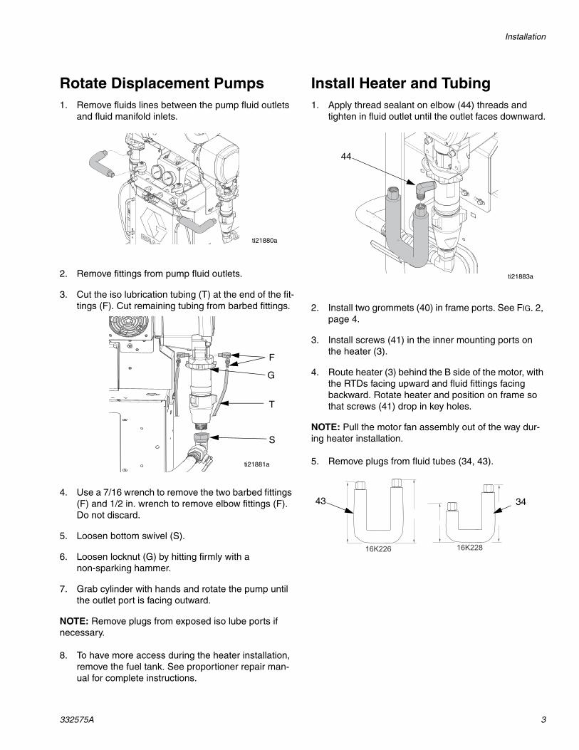
Rotate Displacement Pumps1. Remove fluids lines between the pump fluid outlets
and fluid manifold inlets.
2. Remove fittings from pump fluid outlets.
3. Cut the iso lubrication tubing (T) at the end of the fit-tings (F). Cut remaining tubing from barbed fittings.
4. Use a 7/16 wrench to remove the two barbed fittings (F) and 1/2 in. wrench to remove elbow fittings (F). Do not discard.
5. Loosen bottom swivel (S).
6. Loosen locknut (G) by hitting firmly with a non-sparking hammer.
7. Grab cylinder with hands and rotate the pump until the outlet port is facing outward.
NOTE: Remove plugs from exposed iso lube ports if necessary.
8. To have more access during the heater installation, remove the fuel tank. See proportioner repair man-ual for complete instructions.
Install Heater and Tubing1. Apply thread sealant on elbow (44) threads and
tighten in fluid outlet until the outlet faces downward.
2. Install two grommets (40) in frame ports. See FIG. 2, page 4.
3. Install screws (41) in the inner mounting ports on the heater (3).
4. Route heater (3) behind the B side of the motor, with the RTDs facing upward and fluid fittings facing backward. Rotate heater and position on frame so that screws (41) drop in key holes.
NOTE: Pull the motor fan assembly out of the way dur-ing heater installation.
5. Remove plugs from fluid tubes (34, 43).
ti21880a
ti21881a
G
T
F
S
ti21883a
44
43 34
Installation
4 332575A
6. Install tubes (31, 32) between heater outlets (3) and fluid manifold. Torque to 43 ft-lbs (4.8 N•m).
7. Install u-shaped tubes (34, 43) between the heater (3) and pump. Torque to 43 ft-lbs (4.8 N•m).
NOTE: If longer tubes do not align with manifold, loosen four mounting screws under the manifold. If the tubes do not align with the heater outlet, rotate the elbow (44).
8. Tighten swivel at pump inlet.
9. Tighten locknut (G) by hitting firmly with a non-sparking hammer.
10. Install barbed fittings in the ISO pump. Apply thin film of TSL to barbed fittings. Using two hands, sup-port tubes (T) while pushing straight onto barbed fit-tings. Do not let tubes kink or buckle. Secure each tube with a wire tie between two barbs.
11. Reinstall motor fan and motor shield.
12. Use a 3/8 wrench to tighten heater screws (41).
FIG. 2: Heater Installation
4140
34
40
32, 43
41ti21884a
31
3
44
Installation
332575A 5
Install Low Power Temperature Control Modules (LPTCM)1. Use a hammer to remove knockouts from electrical
enclosure.
2. Install gaskets (21) on inside of enclosure.
3. Install LPTCM bases (15) with eight screws (41).
4. Tighten modules (14) to bases (15).
FIG. 3
21
41
ti21887a15
Installation
6 332575A
Connect Cables
Apply Labels
1. Apply heater and module labels from label on all supplied cables and system parts.
NOTE: Some identification labels will need to be applied to cables already installed on the system.
2. Apply red and blue TCM labels on inside and out-side of enclosure.
Cable Ref. Cable and Label Identification Qty.
11 2
16 1
20 1
36 1
38 2
42 1
TCM-A-5 PWR
TCM-B-5 PWR
TCM-A-CAN TCM-H TCM-H-6 TCM-A
TCM-B-CAN TCM-A TCM-A-CAN TCM-B
J23 TCM-A/BTCM-A-1 J23
TCM-B-1 J23
TCM-B-3 HTR-B
TCM-A-3 HTR-A
TCM-A-2 J24 J24 TCM-A
Installation
332575A 7
Connect Module Wires
See Booster Heater Wiring Diagram, page 9.
1. Open electrical enclosure door.
1. Disconnect 12 black power supply cable from large HPTCM. Remove TCM - H6PSU label.
2. Apply TCMB-CAN PSU label on black power supply cable and connect to LPTCM B base CAN fitting.
3. Connect cables (21, 26, and 30) to modules inside electrical enclosure.
4. Connect power supply cable (21) to circuit breaker.
5. Remove tall wire track cover and press LPTCM cables in track. Bundle cables with zip tie (45) and reinstall wire track cover.
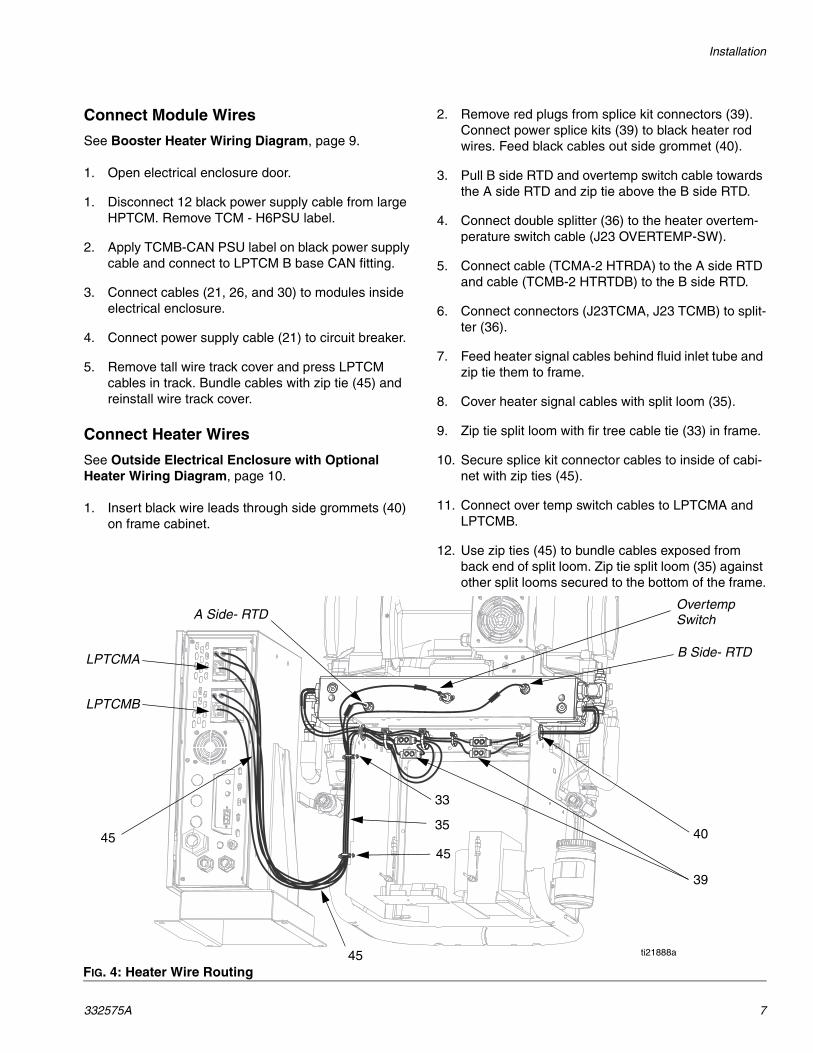
Connect Heater Wires
See Outside Electrical Enclosure with Optional Heater Wiring Diagram, page 10.
1. Insert black wire leads through side grommets (40) on frame cabinet.
2. Remove red plugs from splice kit connectors (39). Connect power splice kits (39) to black heater rod wires. Feed black cables out side grommet (40).
3. Pull B side RTD and overtemp switch cable towards the A side RTD and zip tie above the B side RTD.
4. Connect double splitter (36) to the heater overtem-perature switch cable (J23 OVERTEMP-SW).
5. Connect cable (TCMA-2 HTRDA) to the A side RTD and cable (TCMB-2 HTRTDB) to the B side RTD.
6. Connect connectors (J23TCMA, J23 TCMB) to split-ter (36).
7. Feed heater signal cables behind fluid inlet tube and zip tie them to frame.
8. Cover heater signal cables with split loom (35).
9. Zip tie split loom with fir tree cable tie (33) in frame.
10. Secure splice kit connector cables to inside of cabi-net with zip ties (45).
11. Connect over temp switch cables to LPTCMA and LPTCMB.
12. Use zip ties (45) to bundle cables exposed from back end of split loom. Zip tie split loom (35) against other split looms secured to the bottom of the frame.
FIG. 4: Heater Wire Routing
ti21888a
40
39
B Side- RTD
A Side- RTDOvertemp Switch
4545
33
35
45
LPTCMA
LPTCMB
Installation
8 332575A
13. Install the electrical enclosure back panel (P).
14. Install heater shroud (4) and screws (41) on heater.
Test1. Set rotary dials for LPTCMA and LPTCMB. See
Booster Heater Wiring Diagram, page 9.
2. Power on system. Load software with token (37) in all GCA modules.
3. Check connections for leaks.
P
ti21877a
ti21877a
4
41
41
Electrical Schematics
332575A 9
Electrical Schematics
Booster Heater Wiring Diagram
CIRCUIT BREAKER24J728
ENCLOSURE BOUNDARY
BULKHEAD, 121612
CA
N, 1
2159
7
CA
N,
125
789
POWERSUPPLY, 123374
CAN, 125789
WHT
WHTBLK
16K799BLK
GRN
16K799
HPTCM, 24L950
LPTCM, 24L951
LPTCM, 24L951
CAN, 123652‘CAN-1 TCM-H’
‘TCM-H-6 CAN-1’
‘TCM-H-6 TCM-A’
‘TCM-B-CAN PSU’
‘TCM-B-CAN TCM-A’
‘TCM-A-CAN TCM-B’
‘TCM-A-CAN TCM-H’
‘TCM-A-5 PWR’
‘TCM-B-5 PWR’
‘CAN-1 MCM’
BLK
GRN
To MCM
1
2
4
4
5
3
CT02
CB
01
CB
02
CB
03
CB
04
CB
05
CB
06
CB
07
CB
08
TB
12
TB
11
TB18TB17TB16TB15TB14TB13
{{{
GND
L2
L1
WHTGRN
Rotary switch set to “0”.
Rotary switch set to “A”.
Rotary switch set to “B”.
Torque terminal blocks to 5-7 in.-lbs (0.5-0.8 N•m).
Torque circuit breaker connections to 23-25 in.-lbs (2.5-2.8 N•m).
1
2
3
4
5
Electrical Schematics
10 332575A
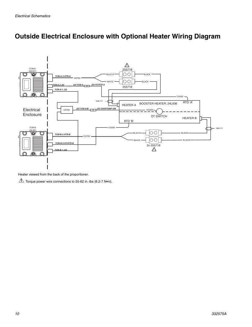
Outside Electrical Enclosure with Optional Heater Wiring Diagram
16A111
BOOSTER HEATER, 24L936
BLACK
BLACK
ElectricalEnclosure
BLACK
BLACK
BLAC K
WHITE
124262
124262
125760 123408J23 OVERTEMP-SWJ23 TCM-A/B
TCM-B-1 J23
TCM-A-1 J23
TCM-A-3 HTR-A
TCM-B-3 HTR-B
TCM-A-2 J24
TCM-B-2 HT-RTD-B
TCM-A24L951
TCM-B24L951
J24 TCM-A J24 HT-RTD-A
125762
125762
255716
2x 255716
255716
16A111
HEATER A
HEATER B
RTD ‘A’
RTD ‘B’
OT SWITCH
BLAC K
WHITE
125358
1
1
Heater viewed from the back of the proportioner.
Torque power wire connections to 55-62 in.-lbs (6.2-7 N•m).1
Parts
332575A 11
Parts
24T552, Boost Heater Upgrade Kit
Replacement Danger and Warning labels, tags, and cards are available at no cost.
All written and visual data contained in this document reflects the latest product information available at the time of publication. Graco reserves the right to make changes at any time without notice.
For patent information, see www.graco.com/patents.
Original instructions. This manual contains English. MM 332575
Graco Headquarters: MinneapolisInternational Offices: Belgium, China, Japan, Korea
GRACO INC. AND SUBSIDIARIES • P.O. BOX 1441 • MINNEAPOLIS MN 55440-1441 • USA
Copyright 2013, Graco Inc. All Graco manufacturing locations are registered to ISO 9001.www.graco.com
Graco Standard WarrantyGraco warrants all equipment referenced in this document which is manufactured by Graco and bearing its name to be free from defects in material and workmanship on the date of sale to the original purchaser for use. With the exception of any special, extended, or limited warranty published by Graco, Graco will, for a period of twelve months from the date of sale, repair or replace any part of the equipment determined by Graco to be defective. This warranty applies only when the equipment is installed, operated and maintained in accordance with Graco’s written recommendations.
This warranty does not cover, and Graco shall not be liable for general wear and tear, or any malfunction, damage or wear caused by faulty installation, misapplication, abrasion, corrosion, inadequate or improper maintenance, negligence, accident, tampering, or substitution of non-Graco component parts. Nor shall Graco be liable for malfunction, damage or wear caused by the incompatibility of Graco equipment with structures, accessories, equipment or materials not supplied by Graco, or the improper design, manufacture, installation, operation or maintenance of structures, accessories, equipment or materials not supplied by Graco.
This warranty is conditioned upon the prepaid return of the equipment claimed to be defective to an authorized Graco distributor for verification of the claimed defect. If the claimed defect is verified, Graco will repair or replace free of charge any defective parts. The equipment will be returned to the original purchaser transportation prepaid. If inspection of the equipment does not disclose any defect in material or workmanship, repairs will be made at a reasonable charge, which charges may include the costs of parts, labor, and transportation.
THIS WARRANTY IS EXCLUSIVE, AND IS IN LIEU OF ANY OTHER WARRANTIES, EXPRESS OR IMPLIED, INCLUDING BUT NOT LIMITED TO WARRANTY OF MERCHANTABILITY OR WARRANTY OF FITNESS FOR A PARTICULAR PURPOSE.
Graco’s sole obligation and buyer’s sole remedy for any breach of warranty shall be as set forth above. The buyer agrees that no other remedy (including, but not limited to, incidental or consequential damages for lost profits, lost sales, injury to person or property, or any other incidental or consequential loss) shall be available. Any action for breach of warranty must be brought within two (2) years of the date of sale.
GRACO MAKES NO WARRANTY, AND DISCLAIMS ALL IMPLIED WARRANTIES OF MERCHANTABILITY AND FITNESS FOR A PARTICULAR PURPOSE, IN CONNECTION WITH ACCESSORIES, EQUIPMENT, MATERIALS OR COMPONENTS SOLD BUT NOT MANUFACTURED BY GRACO. These items sold, but not manufactured by Graco (such as electric motors, switches, hose, etc.), are subject to the warranty, if any, of their manufacturer. Graco will provide purchaser with reasonable assistance in making any claim for breach of these warranties.
In no event will Graco be liable for indirect, incidental, special or consequential damages resulting from Graco supplying equipment hereunder, or the furnishing, performance, or use of any products or other goods sold hereto, whether due to a breach of contract, breach of warranty, the negligence of Graco, or otherwise.
FOR GRACO CANADA CUSTOMERSThe Parties acknowledge that they have required that the present document, as well as all documents, notices and legal proceedings entered into, given or instituted pursuant hereto or relating directly or indirectly hereto, be drawn up in English. Les parties reconnaissent avoir convenu que la rédaction du présente document sera en Anglais, ainsi que tous documents, avis et procédures judiciaires exécutés, donnés ou intentés, à la suite de ou en rapport, directement ou indirectement, avec les procédures concernées.
Graco InformationFor the latest information about Graco products, visit www.graco.com.
TO PLACE AN ORDER, contact your Graco distributor or call to identify the nearest distributor.Phone: 612-623-6921 or Toll Free: 1-800-328-0211 Fax: 612-378-3505