20
BOR format documentation

BOR format documentation

The Bor Format consists of two parts:
• the specification of the storage format
• the specification of the field type
IntroductionFirst, it is assumed that a file matches a recording as an independant logical unit. The file is namedwith a .bor extension.
File name example
50001180101060101P.bor
Table 1. File name structure
5 0001 180101060101
D .bor
Generation
Serial Date Domain Format
Table 2. Domain ID
ID Domain
D Drilling parameters
G Grouting parameters
J JetGrouting parameters
P Ménard Pressuremeter Test
A Continuous Flight Auger Pile (CFA)
L Lugeon Test
V Vibroflotation
Y Dynamic probing and SPT
AbilitiesThe file has the following abilities:
• recording description
• data logs
• non-modification source-file guarantee
1

Format specificationThe bor file is a zip format archive containing the files below:
• A file description that contains technical informations non-specific to the recording type andfield properties, references to data file: description.xml
• Data file, example: data.nc
Data fileData file use the netCDF (3.6+) format. It contain data logs and each variable.
Description fileThe description file contains 2 different types of information:
• non-specific technical information
• field-specific properties
Example of Description file
2

Example of description.xml file (drilling parameters)
<?xml version="1.0" encoding="UTF-8"?><description xmlns="http://www.lim.eu/description"xmlns:xsi="http://www.w3.org/2001/XMLSchema-instance"xsi:schemaLocation="http://www.lim.eu/description description.xsd"> <filename>50001180101070101D</filename> <creation>2018-01-01T07:01:01+01:00</creation> <modification>2018-01-01T07:31:01+01:00</modification> <project_ref>Bor-Format</project_ref> <borehole_ref>SP1</borehole_ref> <cell> <mcc>208</mcc> <mnc>01</mnc> <cellid>31605177</cellid> <lac>21301</lac> </cell> <operator>ROBERT</operator> <device> <serial>50001</serial> <version>1.4</version> <build>20180101</build> </device> <drilling> <machine_ref>DRIL</machine_ref> <method>DRLMTD_RTR</method> <tool>DRLBIT_CNTCI</tool> <tool_diameter unit="mm">66</tool_diameter> <rod_length unit="m">2</rod_length> </drilling> <convention version="1.1"> <parameters phase="DRILL"> <inclination> <X unit="degree">91.9</X> <Y unit="degree">88.6</Y> </inclination> <effective_duration unit="s">1800.00</effective_duration> <logfile>data.nc</logfile> </parameters> </convention></description>
Non-specific technical informationTable 3. Non-specific technical information
3
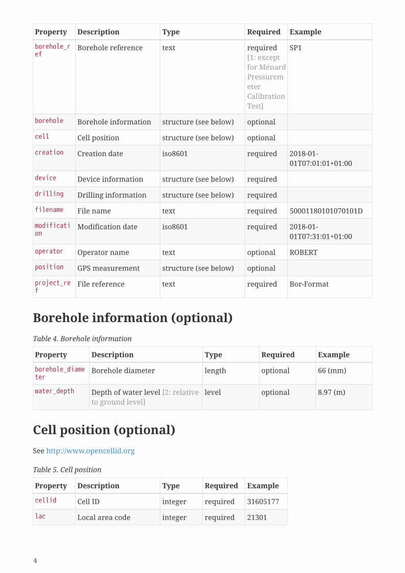
Property Description Type Required Example
borehole_ref
Borehole reference text required[1: exceptfor MénardPressuremeterCalibrationTest]
SP1
borehole Borehole information structure (see below) optional
cell Cell position structure (see below) optional
creation Creation date iso8601 required 2018-01-01T07:01:01+01:00
device Device information structure (see below) required
drilling Drilling information structure (see below) required
filename File name text required 50001180101070101D
modification
Modification date iso8601 required 2018-01-01T07:31:01+01:00
operator Operator name text optional ROBERT
position GPS measurement structure (see below) optional
project_ref
File reference text required Bor-Format
Borehole information (optional)Table 4. Borehole information
Property Description Type Required Example
borehole_diameter
Borehole diameter length optional 66 (mm)
water_depth Depth of water level [2: relativeto ground level]
level optional 8.97 (m)
Cell position (optional)See http://www.opencellid.org
Table 5. Cell position
Property Description Type Required Example
cellid Cell ID integer required 31605177
lac Local area code integer required 21301
4

Property Description Type Required Example
mcc Mobile country code integer required 208
mnc Mobile network code integer required 1
GPS measurement (optional)Table 6. GPS measurement (WGS84)
Property Description Type Required Example
altitude Altitude length required 186 (m)
eph Standard deviation of horizontal positionerror
length required 12.229 (m)
epv Standard deviation of vertical positionerror
length required 13.9042 (m)
latitude Latitude angle required 45.75905881 (degree)
longitude Longitude angle required 4.91944618 (degree)
Device informationTable 7. Device information
Property Description Type Required Example
build Build version text optional 20180101
serial Serial number integer required 50001
version Hardware version text optional 1.4
Drilling informationTable 8. Drilling information
Property Description Type Required Example
bit_mass Drilling tool mass mass optional 10 (kg)
fluid Drilling fluid code (see below) optional DRLFLD_WBM
holdback_area
Surface of holdbackpressure
area optional 301 (cm2)
machine_ref Drilling machine text optional GEODRIL
method Drilling method code (see below) optional DRLMTD_RTR
rod_mass Drilling rod mass mass optional 20 (kg)
5

Property Description Type Required Example
rod_length Drilling rod length length optional 2 (m)
thrust_area Surface of thrust pressure area optional 401 (cm2)
tool Drilling tool code (see below) optional DRLBIT_CNTCI
tool_diameter
Drilling tool diameter length optional 66 (mm)
torque_factor
Torque factor decimal optional 112
Table 9. Drilling method codes
Drilling method Description
DRLMTD_HA Auger
DRLMTD_CFA Continuous flight auger
DRLMTD_ADM Auger with drilling mud
DRLMTD_HSA Hollow Stem Auger
DRLMTD_DTM Disintegrating tool with mud circulation
DRLMTD_COR Core drilling
DRLMTD_RTR Rotary drilling
DRLMTD_RRFFM Rotary reverse flow of flushing medium
DRLMTD_RTRPRC Rotary percussion
DRLMTD_RPM Rotary percussion with mud
DRLMTD_DTH Downhole hammer
DRLMTD_DRI Driving
DRLMTD_DS Driven sampler
DRLMTD_DST Driven slotted tube
DRLMTD_STDTM Slotted tube with inside disintegrating tool and mudcirculation
DRLMTD_CPD Cable percussion drilling
DRLMTD_VDS Vibro driven sampler
DRLMTD_VD Vibration drilling
DRLMTD_VS Vibro-sinking
DRLMTD_PS Push sampler
Table 10. Drilling tool (bit) codes
6

Drilling tool Description
DRLBIT_BLD Blade bit
DRLBIT_BLD2 2 Blades bit
DRLBIT_BLD3 3 Blades bit
DRLBIT_BLD4 4 Blades bit
DRLBIT_BLDTIP Bladed tool tip
DRLBIT_BLDTUB Bladed tool with tube topped
DRLBIT_JET Jet bit
DRLBIT_RTDK Rotary disk bit
DRLBIT_FLTCHS Flat chisel
DRLBIT_CRSCHS Cross chisel
DRLBIT_STPCHS Cross Cut Step bit with TCI
DRLBIT_BTT Buttons bit (Rotary percussion)
DRLBIT_BTTDTH Buttons bit DTH
DRLBIT_BTTODX Button bit ODEX
DRLBIT_CTTPDC Cutter bit PDC (polycrystalline diamondcompact)
DRLBIT_CTTGHI Cutter bit GHI (grit hotpressed inserts)
DRLBIT_STBB Stubber (heavy tool)
DRLBIT_CACH California chisel bit
DRLBIT_BICN Bicone bit
DRLBIT_TRCN Tricone bit
DRLBIT_CNST Tricone Steeltooth bit
DRLBIT_CNTCI Tricone TCI (Tungsten Carbide Insert)
DRLBIT_SPRL Spiral bit
DRLBIT_AUG Auger
DRLBIT_ABCK Auger with bucket
DRLBIT_HA Hand Auger
DRLBIT_HSA Hollow Stem Auger
DRLBIT_CFA Continuous Flight Auger
DRLBIT_COR Core bit
DRLBIT_TC Tungsten carbide set
7

Drilling tool Description
DRLBIT_GTS Geotechnical saw-tooth carbide set
DRLBIT_PCD Polycrystalline diamond core bit
DRLBIT_TSP Thermally stable polycrystalline set
DRLBIT_STCB Single-tube corebarrel
DRLBIT_DTCB Double-tube corebarrel
DRLBIT_TTCB Triple-tube corebarrel
DRLBIT_DTCBXT DD/TT corebarrel with extended inner tube
DRLBIT_OSTW Open-sampler thin-walled (Shelby)
DRLBIT_OSTKW Open-sampler thick-walled
DRLBIT_HPS Hydraulic Piston samplers
DRLBIT_PSTKW Piston samplers, thick-walled
DRLBIT_PSTW Piston samplers, thin-walled
DRLBIT_CPDS Bit with shell (or bailer)
DRLBIT_CPDC Bit with clay cutter
DRLBIT_CPSS Sectional shell
Table 11. Drilling fluid codes
Drilling fluid Description
DRLFLD_AIR Air
DRLFLD_WTR Water
DRLFLD_AIRWTR Air-Water
DRLFLD_AIRPLM Air-Polymer
DRLFLD_WBM Water-based mud
DRLFLD_WBMSHL Water-Shale-based mud
DRLFLD_WBMPLM Dry-polymer-based mud
DRLFLD_WBMLSF Lignosulfonate-based mud
DRLFLD_WBMSEA Sea-Water-based mud
DRLFLD_WBMNACL Saturated-Salt-based mud
DRLFLD_WBMLIM Lime-based mud
DRLFLD_WBMCLC Calcium-based mud
DRLFLD_OBM Oil-based mud
DRLFLD_SBM Synthetic-based mud
8

Field types (convention)• Drilling Parameters convention
• Ménard Pressuremeter Test convention
Drilling Parameters convention
Definition
Drilling Parameters convention combine drilling parameters recorded during drilling toolmovement according to time or depth.
The convention is simply named parameters.
Three different field types are actually supported by this format. Each field type can have differentphases.
Table 12. Parameters phases
Field type Phase
Parameters recorded during drilling DRILL
Jet grouting parameters recorded during drilling andinjection
JETDOWN, JETUP, PREJETDOWN, PREJETUP
CFA Pile parameters recorded during drilling andconcreting
PILEDOWN, PILEUP
Example of parameters convention
Example of parameters convention
<convention version="1.1"> <parameters phase="DRILL"> <inclination> <X unit="degree">91.9</X> <Y unit="degree">88.6</Y> </inclination> <effective_duration unit="s">3789.00</effective_duration> <logfile>data.nc</logfile> </parameters> </convention>
Properties
Table 13. Parameters information
9

Property Description Type Required Example
effective_duration
Drilling effective duration (out of break) duration required 3789.00 (s)
inclination Tilt of the drill mast structure(see below)
optional
logfile Name of data file text required data.nc
Table 14. Inclination information (optional)
Property Description Type Required Example
X Inclination depending on X direction angle required 91.9 (degree)
Y Inclination depending on Y direction angle required 88.6 (degree)
Data file
Data file is made with the netCDF (3.6+) format. They contain data logs and log names declarations(variables).
Example of data.nc dump
Example of data file from 50001180101070101D.bor (data.nc dump to data.cdl format)
Data.cdl example
netcdf data {dimensions: time = UNLIMITED ; // (976 currently)variables: float time(time) ; time:unit = "s" ; time:label = "Temps" ; float DEPTH(time) ; DEPTH:unit = "m" ; DEPTH:label = "Prof." ; float AS(time) ; AS:unit = "m/h" ; AS:label = "VIA" ; AS:scale_max = 1500.f ; int EVP(time) ; EVP:label = "evt-part" ; int EVR(time) ; EVR:label = "evt-new-rod" ; float TP(time) ; TP:unit = "bar" ; TP:label = "PO" ; TP:scale_max = 300.f ; float IP(time) ; IP:unit = "bar" ;
10

IP:label = "PI" ; IP:scale_max = 50.f ; float TQ(time) ; TQ:unit = "bar" ; TQ:label = "CR" ; TQ:scale_max = 300.f ; float SP(time) ; SP:unit = "bar" ; SP:label = "PF" ; SP:scale_max = 300.f ;data:
time = 0, 2.2, 2.4, 2.6, 2.8, 3, 3.2, 3.4, 3.6, 3.8, 4, 4.2, 4.4, 4.6, 4.8, ... 4037.6, 4042.4, 4043.6, 4046, 4047, 4163.4 ;
DEPTH = 0, 0.02, 0.08, 0.15, 0.21, 0.28, 0.35, 0.42, 0.48, 0.55, 0.62, 0.69, ... 14.96, 14.97, 14.98, 15 ;
AS = 0, 31.45398, 1178.385, 1148.298, 1138.269, 1228.529, 1258.615, .... 15.87894, 53.15267, 20.05761 ;
EVP = 0, 0, 0, 0, 0, 0, 0, 0, 0, 0, 0, 0, 0, 0, 0, 0, 0, 0, 0, 0, 0, 0, 0, ... 0, 0, 0, 0, 0, 0, 0, 0, 0, 0, 0, 0, 0, 0, 0, 0, 0 ;
EVR = 0, 0, 0, 0, 0, 0, 0, 0, 0, 0, 0, 0, 0, 0, 0, 0, 0, 0, 0, 0, 0, 0, 0, ... 0, 0, 0, 0, 0, 0, 0, 0, 0, 0, 0, 0, 0, 0, 0, 0, 0 ;
TP = 7.42, 7.42, 70.89, 70.89, 70.89, 70.89, 70.89, 70.89, 70.89, 70.89, ... 73.34, 74.56, 74.56, 74.56, 70.89, 4.98 ;
IP = 1.31, 1.31, 1.31, 1.31, 1.31, 1.31, 1.31, 1.31, 1.31, 1.31, 1.31, 1.31, ... 12.3, 4.98, 7.42, 17.18, 11.08, 7.42, 14.74, 12.3, 1.31 ;
TQ = 4.98, 4.98, 6.2, 6.2, 2.53, 4.98, 4.98, 4.98, 4.98, 4.98, 4.98, 4.98, ... 74.56, 86.76, 85.54, 85.54, 64.79 ;
SP = 1.31, 2.53, 1.31, 0, 4.98, 1.31, 0.09, 1.31, 6.2, 0, 4.98, 1.31, 2.53, ... 2.53, 1.31, 2.53, 1.31, 2.53, 4.98, 0, 4.98, 4.98, 7.42 ;}
11

Parameters Log names
Table 15. Drilling Parameters log names
Log name Description Type Required Remark
time Measured time float required NETCDF dimension
DEPTH Measured penetration length float required
AS Advance Speed (penetration rate) float required
EVP Event Particular integer optional
EVR Event new Rod integer optional
EVS Event start relay float optional
TP Tool pressure float optional
IP Injection pressure float optional
TQ Rotation pressure (Torque) float optional
TQC Casing Rotation pressure float optional
RSP Rotation Speed float optional
RSPC Casing Rotation Speed float optional
HP Holding Pressure float optional
SP Striking Pressure float optional
RV Reflected Vibration float optional
IF Injection Flow (inlet flow) float optional
OF Drilling fluid outflow (Outlet Flow) float optional
IV Injection Volume float optional
OV Outlet Volume float optional
AP Air Pressure float optional
AF Air Flow float optional
AV Air Volume float optional
WF Water Flow float optional
WP Water Pressure float optional
WV Water Volume float optional
ECM Electrical Conductivity of Mud float optional
PHM pH of Mud float optional
DO2M Dissolved O2 in Mud float optional
TEMPM Temperature of Mud float optional
12

Ménard Pressuremeter Test convention
Definition
Ménard Pressuremeter Test is performed by the radial expansion of a tricell probe placed in theground. This test is specified by the standard ISO 22476-4.
The convention is simply named pressuremeter.
Three different pressuremeter test types are supported by this format.
Table 16. Ménard Pressuremeter Test types
Test type Description
ground Ménard pressuremeter test in natural soils
volume_loss Equipment volume loss calibration test
pressure_loss Probe pressure loss calibration test
Example of Ménard Pressuremeter Test convention
Example of Ménard Pressuremeter Test convention (ground test type)
<convention version="1.2"> <pressuremeter> <cu_ref>CPVA001</cu_ref> <ground> <pressure_loss_filename>50001180101062101P.bor</pressure_loss_filename> <cu_height unit="m">1</cu_height> <test_depth unit="m">2</test_depth> <logfile>data.nc</logfile> </ground> </pressuremeter> </convention>
Common properties
Table 17. Pressuremeter common properties
Property Description Type Required Example
cu_ref Control Unit ID text optional CPVA001
Volume loss test
13

Volume loss example
<volume_loss> <cover_type>CVR_RUBBER</cover_type> <probe_type>PRB_G</probe_type> <central_cell_diameter unit="mm">56</central_cell_diameter> <central_cell_length unit="mm">210</central_cell_length> <tubing_type>TUB_COAXIAL</tubing_type> <tubing_length unit="m">25</tubing_length> <calibration_cylinder_diameter unit="mm">60</calibration_cylinder_diameter> <membrane_pressure_loss unit="bar">0.54</membrane_pressure_loss> <slotted_tube>true</slotted_tube> <central_cell_diameter_inside_slotted_tube unit="mm"> 44 </central_cell_diameter_inside_slotted_tube> <logfile>data.nc</logfile> </volume_loss>
Table 18. Volume loss properties
Property Description Type Required Example
calibration_cylinder_diameter
Calibration cylinderdiameter
length required 66 (mm)
central_cell_diameter
Central cell diameter length required 56 (mm)
central_cell_length
Central cell length length required 210 (mm)
cover_type Cover type code (see below) required CVR_RUBBER
membrane_pressure_loss
Membrane pressure loss pressure required 0.054 (MPa)
probe_type Type of pressuremeterprobe
code (see below) required PRB_G
tubing_length
Tubing length length required 25 (m)
tubing_type Tubing type code (see below) required TUB_COAXIAL
logfile Name of data file text required data.nc
Table 19. Cover type codes
Cover type Description
CVR_RUBBER Rubber
CVR_REINFORCED_MESH Reinforced mesh
CVR_METALIC_MESH Metallic mesh
14

Cover type Description
CVR_METALIC_STRIPS Metallic strips
Table 20. Probe type codes
Probe type Description
PRB_G Type of pressuremeter probe where the central measuring cell is formed by adedicated membrane over which an external membrane is fitted to form theguard cells
PRB_E Type of pressuremeter probe where the three cells are formed by three separatemembranes in line
Table 21. Tubing type codes
Tubing type Description
TUB_TWIN Parallel lines
TUB_COAXIAL Coaxial line
Pressure loss test
Pressure loss example
<pressure_loss> <volume_loss_filename>50001180101060101P.bor</volume_loss_filename> <logfile>data.nc</logfile> </pressure_loss>
Table 22. Pressure loss properties
Property Description Type Required Example
volume_loss_filename
Name of associated volume loss test text required 50001180101060101P.bor
logfile Name of data file text required data.nc
Ground test
Ground test example
<ground> <pressure_loss_filename>50001180101062101P.bor</pressure_loss_filename> <cu_height unit="m">1</cu_height> <test_depth unit="m">2</test_depth> <logfile>data.nc</logfile> </ground>
Table 23. Ground properties
15

Property Description Type Required
Example
cu_height Height of the control unit relative to groundlevel
length required
1 (m)
pressure_loss_filename
Name of associated pressure loss test text required
50001180101060101P.bor
test_depth Depth of the test relative to ground level length required
2 (m)
logfile Name of data file text required
data.nc
Data file
Data file is made with the netCDF (3.6+) format. They contain data logs and log names declarations(variables).
Example of data.nc dump
Example of data file (data.nc dump to data.cdl format)
Data.cdl example
netcdf data {dimensions: time = UNLIMITED ; // (12 currently)variables: float time(time) ; time:unit = "s" ; time:label = "time" ; float PR1(time) ; PR1:unit = "bar" ; PR1:label = "PR1S" ; float PR15(time) ; PR15:unit = "bar" ; PR15:label = "PR15S" ; float PR30(time) ; PR30:unit = "bar" ; PR30:label = "PR30S" ; float PR60(time) ; PR60:unit = "bar" ; PR60:label = "PR60S" ; float PG1(time) ; PG1:unit = "bar" ; PG1:label = "PG1S" ; float PG15(time) ; PG15:unit = "bar" ; PG15:label = "PG15S" ; float PG30(time) ;
16

PG30:unit = "bar" ; PG30:label = "PG30S" ; float PG60(time) ; PG60:unit = "bar" ; PG60:label = "PG60S" ; float V1(time) ; V1:unit = "cm3" ; V1:label = "V1S" ; float V15(time) ; V15:unit = "cm3" ; V15:label = "V15S" ; float V30(time) ; V30:unit = "cm3" ; V30:label = "V30S" ; float V60(time) ; V60:unit = "cm3" ; V60:label = "V60S" ; V60:scale_max = 500.f ; float CREEP(time) ; CREEP:unit = "cm3" ; CREEP:label = "fluage" ; float DELT60(time) ; DELT60:unit = "cm3" ; DELT60:label = "delt60" ;data:
time = 80, 141, 205, 273, 339, 410, 477, 546, 616, 687, 759, 836 ;
PR1 = 0.48, 0.96, 1.48, 2.62, 3.46, 5.67, 7.62, 11.59, 15.6, 20.53, 25.49, 30.46 ;
PR15 = 0.51, 1, 1.45, 2.56, 3.52, 5.57, 7.48, 11.53, 15.48, 20.52, 25.48, 30.48 ;
PR30 = 0.49, 1.02, 1.51, 2.56, 3.5, 5.55, 7.47, 11.5, 15.47, 20.53, 25.49, 30.48 ;
PR60 = 0.46, 0.98, 1.5, 2.55, 3.47, 5.52, 7.49, 11.56, 15.47, 20.48, 25.5, 30.5 ;
PG1 = 0.12, 0.12, 0.52, 1.5, 2.6, 4.52, 6.48, 10.48, 14.51, 19.54, 24.59, 29.53 ;
PG15 = 0.14, 0.12, 0.53, 1.5, 2.54, 4.53, 6.51, 10.5, 14.56, 19.52, 24.52, 29.5 ;
PG30 = 0.12, 0.12, 0.53, 1.52, 2.55, 4.53, 6.5, 10.5, 14.52, 19.55, 24.5, 29.53 ;
PG60 = 0.14, 0.14, 0.56, 1.53, 2.53, 4.53, 6.51, 10.51, 14.51, 19.53, 24.53, 29.55 ;
17

V1 = 37, 51, 81, 105, 116, 136, 152, 178, 207, 240, 282, 348 ;
V15 = 43, 65, 89, 108, 119, 139, 155, 185, 212, 249, 295, 369 ;
V30 = 46, 72, 91, 110, 121, 141, 156, 187, 215, 254, 304, 388 ;
V60 = 48, 77, 95, 111, 121, 142, 158, 189, 219, 259, 315, 414 ;
CREEP = 2, 5, 4, 1, 0, 1, 2, 2, 4, 5, 11, 26 ;
DELT60 = 48, 29, 18, 16, 10, 21, 16, 31, 30, 40, 56, 99 ;}
Pressuremeter Log names
Table 24. Pressuremeter log names
Logname
Description Type Required
Remark
time Measured time float required NETCDFdimension
PR1 Liquid pressure at 1 s [3: Liquid pressure applied by thecontrol unit indicator to the the central cell as read x safter the beginning of the pressure hold]
float required
PR15 Liquid pressure at 15 s [3: Liquid pressure applied by thecontrol unit indicator to the the central cell as read x safter the beginning of the pressure hold]
float required
PR30 Liquid pressure at 30 s [3: Liquid pressure applied by thecontrol unit indicator to the the central cell as read x safter the beginning of the pressure hold]
float required
PR60 Liquid pressure at 60 s [3: Liquid pressure applied by thecontrol unit indicator to the the central cell as read x safter the beginning of the pressure hold]
float required
PG1 Gas pressure at 1 s [4: Gas pressure applied by the controlunit indicator to the guard cells as read x s after thebeginning of the pressure hold]
float required
PG15 Gas pressure at 15 s [4: Gas pressure applied by the controlunit indicator to the guard cells as read x s after thebeginning of the pressure hold]
float required
PG30 Gas pressure at 30 s [4: Gas pressure applied by the controlunit indicator to the guard cells as read x s after thebeginning of the pressure hold]
float required
18

Logname
Description Type Required
Remark
PG60 Gas pressure at 60 s [4: Gas pressure applied by the controlunit indicator to the guard cells as read x s after thebeginning of the pressure hold]
float required
V1 Volume of injected liquid at 1 s [5: Volume injected in thecentral measuring cell as read x s after the beginning ofthe pressure hold]
float required
V15 Volume of injected liquid at 15 s [5: Volume injected in thecentral measuring cell as read x s after the beginning ofthe pressure hold]
float required
V30 Volume of injected liquid at 30 s [5: Volume injected in thecentral measuring cell as read x s after the beginning ofthe pressure hold]
float required
V60 Volume of injected liquid at 60 s [5: Volume injected in thecentral measuring cell as read x s after the beginning ofthe pressure hold]
float required
CREEP Difference in volumes recorded at 60 s and at 30 s at eachpressure hold
float required
DELT60 60 s injected volume change between successive pressureholds
float required
19


![[MS-CSDLBI-Diff]: Conceptual Schema Definition File Format ...MS... · Conceptual Schema Definition File Format with Business ... Conceptual Schema Definition File Format with Business](https://static.documents.pub/doc/80x56/5cd72bdf88c993dc268c1c36/ms-csdlbi-diff-conceptual-schema-definition-file-format-ms-conceptual.jpg)


