12
Bosch BVA Series Air Handler 2-3-4-5 Ton Capacity R410A Product Specifications
Bosch BVA Series Air Handler2-3-4-5 Ton CapacityR410A
Product Specifi cations

2 | Bosch IDS BVA Product Specifi cations
06.2016 | Bosch Thermotechnology Corp.Data subject to change
Product Specifi cations Bosch IDS BVA | 3
Bosch Thermotechnology Corp. | 06.2016 Data subject to change
Table of Contents
1 Product features 4
2 Nomenclature 5
3 Product specifi cations 6
4 Dimensions 7
5 Blower Data 8
6 Heater Kit Data 9

4 | Bosch IDS BVA Product Specifi cations
06.2016 | Bosch Thermotechnology Corp.Data subject to change
1 Product features
Multi-speed ECM blower motor.
Factory-installed TXV metering.
Multi-position Installation - upflow or horizontal right standard;field convertible to horizontal left or downflow.
Multiple electrical entry locations.
Field-installed electric heater kits 5, 7.5, 10, 15, 20KW available as an accessory.
Dual front panel design for ease of maintenance.
Blower and coil easy slide out for ease of maintenance.
Fully-insulated cabinet design.
Horizontal and vertical condensate drain pans standard.
Condensate drain pan is polymer with UVC inhibitor.
Primary and secondary condensate drain fittings.
Factory-sealed cabinet certified to achieve 2% or less airleakage rate at 1.0 inch water column.
Integrated filter rack with tool-less door access.
AHRI and ETL Listed.
Product Specifi cations Bosch IDS BVA | 5
Bosch Thermotechnology Corp. | 06.2016 Data subject to change
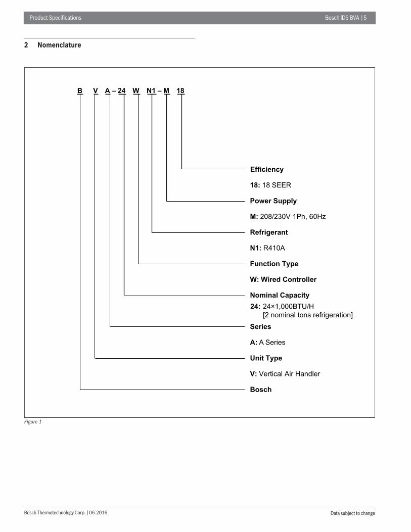
2 Nomenclature
B V A – 24 W N1 – M 18
Efficiency
18: 18 SEER
Power Supply
M: 208/230V 1Ph, 60Hz
Refrigerant
N1: R410A
Function Type
W: Wired Controller
Nominal Capacity 24: 24×1,000BTU/H
[2 nominal tons refrigeration] Series
A: A Series
Unit Type
V: Vertical Air Handler
Bosch
Figure 1
6 | Bosch IDS BVA Product Specifi cations
06.2016 | Bosch Thermotechnology Corp.Data subject to change
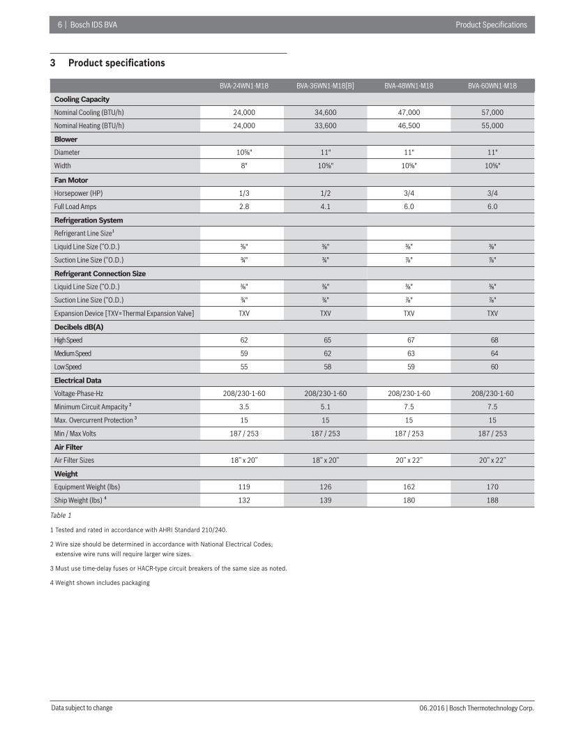
3 Product specifi cations
BVA-24WN1-M18 BVA-36WN1-M18[B] BVA-48WN1-M18 BVA-60WN1-M18
Cooling Capacity
Nominal Cooling (BTU/h) 24,000 34,600 47,000 57,000
Nominal Heating (BTU/h) 24,000 33,600 46,500 55,000
Blower
Diameter 10⅝" 11" 11" 11"
Width 8" 10⅝" 10⅝" 10⅝"
Fan Motor
Horsepower (HP) 1/3 1/2 3/4 3/4
Full Load Amps 2.8 4.1 6.0 6.0
Refrigeration System
Refrigerant Line Size¹
Liquid Line Size (“O.D.) ⅜" ⅜" ⅜" ⅜"
Suction Line Size (“O.D.) ¾" ¾" ⅞" ⅞"
Refrigerant Connection Size
Liquid Line Size (“O.D.) ⅜" ⅜" ⅜" ⅜"
Suction Line Size (“O.D.) ¾" ¾" ⅞" ⅞"
Expansion Device [TXV=Thermal Expansion Valve] TXV TXV TXV TXV
Decibels dB(A)
High Speed 62 65 67 68
Medium Speed 59 62 63 64
Low Speed 55 58 59 60
Electrical Data
Voltage-Phase-Hz 208/230-1-60 208/230-1-60 208/230-1-60 208/230-1-60
Minimum Circuit Ampacity ² 3.5 5.1 7.5 7.5
Max. Overcurrent Protection ³ 15 15 15 15
Min / Max Volts 187 / 253 187 / 253 187 / 253 187 / 253
Air Filter
Air Filter Sizes 18’’ x 20’’ 18’’ x 20’’ 20’’ x 22’’ 20’’ x 22’’
Weight
Equipment Weight (lbs) 119 126 162 170
Ship Weight (lbs) ⁴ 132 139 180 188
Table 1
1 Tested and rated in accordance with AHRI Standard 210/240.
2 Wire size should be determined in accordance with National Electrical Codes; extensive wire runs will require larger wire sizes.
3 Must use time-delay fuses or HACR-type circuit breakers of the same size as noted.
4 Weight shown includes packaging
Product Specifi cations Bosch IDS BVA | 7
Bosch Thermotechnology Corp. | 06.2016 Data subject to change
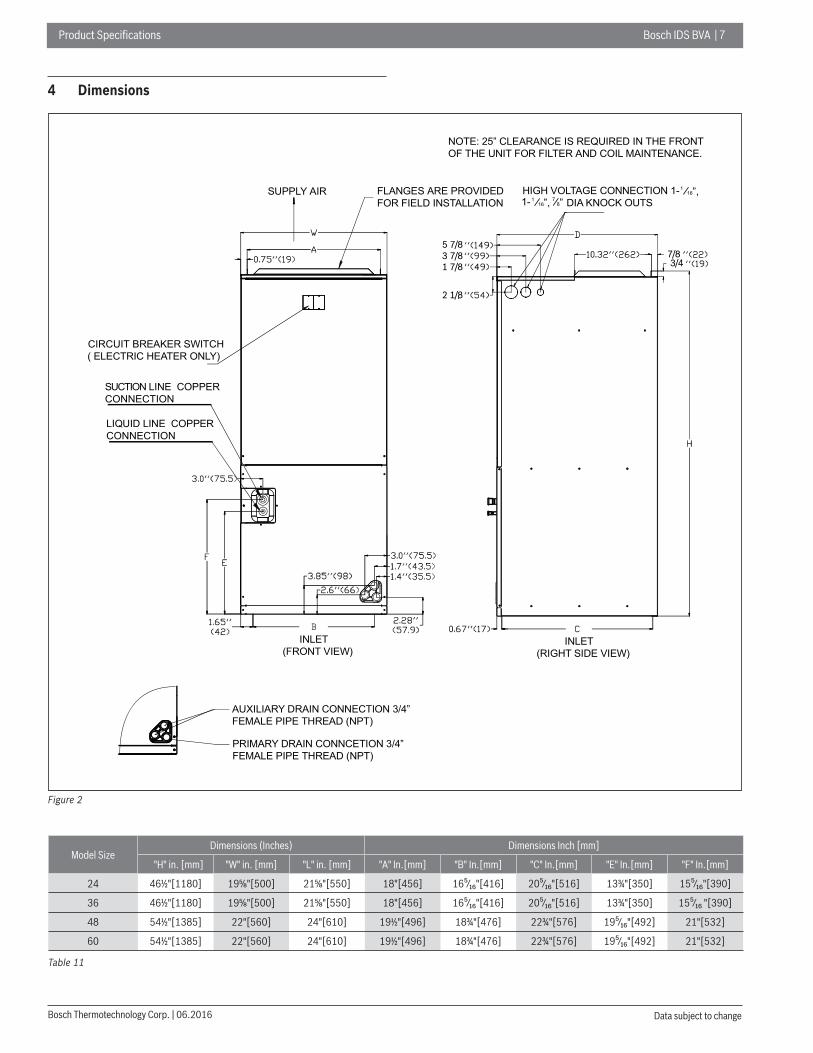
4 Dimensions
NOTE: 25” CLEARANCE IS REQUIRED IN THE FRONT OF THE UNIT FOR FILTER AND COIL MAINTENANCE.
SUPPLY AIR FLANGES ARE PROVIDED FOR FIELD INSTALLATION
HIGH VOLTAGE CONNECTION 1- DIA KNOCK OUTS
CIRCUIT BREAKER SWITCH( ELECTRIC HEATER ONLY)
SUCTION LINE COPPER CONNECTION
LIQUID LINE COPPER CONNECTION
AUXILIARY DRAIN CONNECTION 3/4” FEMALE PIPE THREAD (NPT)
PRIMARY DRAIN CONNCETION 3/4” FEMALE PIPE THREAD (NPT)
INLET(FRONT VIEW)
INLET(RIGHT SIDE VIEW)
16”, 1/16”, 1/1- 8”7/
5 7/83 7/81 7/8
2 1/8
7/83/4
Figure 2
Model SizeDimensions (Inches) Dimensions Inch [mm]
"H" in. [mm] "W" in. [mm] "L" in. [mm] "A" In.[mm] "B" In.[mm] "C" In.[mm] "E" In.[mm] "F" In.[mm]
24 46½"[1180] 19⅝"[500] 21⅝"[550] 18"[456] 16⁵⁄₁₆"[416] 20⁵⁄₁₆"[516] 13¾"[350] 15⁵⁄₁₆"[390]
36 46½"[1180] 19⅝"[500] 21⅝"[550] 18"[456] 16⁵⁄₁₆"[416] 20⁵⁄₁₆"[516] 13¾"[350] 15⁵⁄₁₆ "[390]
48 54½"[1385] 22"[560] 24"[610] 19½"[496] 18¾"[476] 22¾"[576] 19⁵⁄₁₆"[492] 21"[532]
60 54½"[1385] 22"[560] 24"[610] 19½"[496] 18¾"[476] 22¾"[576] 19⁵⁄₁₆"[492] 21"[532]
Table 11

8 | Bosch IDS BVA Product Specifi cations
06.2016 | Bosch Thermotechnology Corp.Data subject to change
5 Blower Data
Airfl ow performance
Airfl ow performance data is based on cooling performance with a coil and no fi lter in place. Check the performance table for appropriate unit size selection. External static pressure should stay within the minimum and maximum limits shown in the table below in order to ensure proper operation of both cooling,heating, and electric heating operation.
Air Handler Model Size Motor Speed
SCFMExternal Static Pressure-Inches W.C.[kPa]
0.1[.02] 0.2[. 05] 0.3[.07] 0.4[.10] 0.5[.12] 0.6[.15] 0.7[.17] 0.8[.20]
24
Tap(5)SCFM 1016 955 914 870 827 790 741 691 657Watts 139 146 157 165 174 185 195 202 209
Tap(4)SCFM 955 892 853 804 768 729 671 630 ---Watts 118 125 135 142 152 162 169 178 ---
Tap(3)-Default Setting
SCFM 927 829 789 739 701 643 597 --- ---Watts 109 105 113 121 131 137 147 --- ---
Tap(2)SCFM 887 766 671 631 567 522 465 --- ---Watts 97 87 83 93 99 108 112 --- ---
Tap(1)SCFM 829 698 547 366 347 277 234 --- ---Watts 81 71 60 54 60 64 72 --- ---
36
Tap(5)SCFM 1452 1403 1343 1287 1214 1144 1085 1022 968Watts 253 264 271 284 296 303 313 324 329
Tap(4)-Default Setting
SCFM 1255 1203 1150 1062 995 920 854 797 719Watts 170 182 193 201 212 221 229 239 244
Tap(3)SCFM 1109 1050 985 897 841 841 766 702 617Watts 126 136 147 154 164 170 180 187 195
Tap(2)SCFM 1020 907 818 733 673 586 520 --- ---Watts 103 98 109 114 124 129 139 --- ---
Tap(1)SCFM 962 807 627 551 450 380 296 --- ---Watts 90 80 71 79 83 93 96 --- ---
48
Tap(5)SCFM 2072 2013 1935 1923 1878 1830 1783 1736 1688Watts 447 464 489 497 514 530 545 558 570
Tap(4)SCFM 1860 1816 1735 1679 1640 1591 1542 1504 1481Watts 348 364 383 395 408 418 429 451 463
Tap(3)-Default Setting
SCFM 1702 1651 1560 1547 1497 1438 1385 1331 1280Watts 268 281 304 312 325 337 349 361 375
Tap(2)SCFM 1393 1358 1179 1155 1139 1074 1020 964 896Watts 227 234 258 269 270 283 296 313 325
Tap(1)SCFM 1365 1239 1078 1050 965 904 886 831 797Watts 220 226 243 264 269 281 293 301 317
60
Tap(5)SCFM 2054 2015 1947 1928 1886 1846 1804 1742 1654Watts 470 495 518 528 542 553 569 567 548
Tap(4)-Default Setting
SCFM 1883 1840 1783 1754 1712 1670 1622 1579 1541Watts 367 388 411 420 422 445 454 466 479
Tap(3)SCFM 1721 1674 1582 1566 1528 1484 1443 1401 1345Watts 289 305 327 330 341 353 365 378 387
Tap(2)SCFM 1515 1463 1386 1358 1308 1262 1215 1153 1073Watts 205 218 235 239 251 263 276 285 301
Tap(1)SCFM 1337 1265 1156 1148 1095 984 955 963 789Watts 145 157 173 178 186 197 212 225 235
Table 3
- Bold outlined areas represent airfl ow outside of the required 300-450 cfm/ton range.
SCFM means Standard Cubic Foot per Minute.
Airfl ow based upon Air Handler Unit operating at 230V with no electric heater kit and no fi lter. Airfl ow at 208V is approximately the same as 230V.
Product Specifi cations Bosch IDS BVA | 9
Bosch Thermotechnology Corp. | 06.2016 Data subject to change
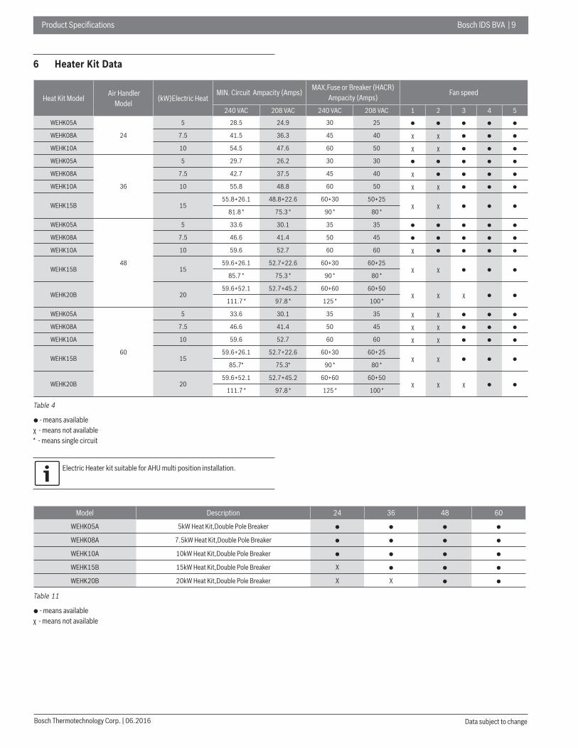
6 Heater Kit Data
Heat Kit Model Air Handler
Model (kW)Electric Heat
MIN. Circuit Ampacity (Amps) MAX.Fuse or Breaker (HACR)
Ampacity (Amps)Fan speed
240 VAC 208 VAC 240 VAC 208 VAC 1 2 3 4 5
WEHK05A
24
5 28.5 24.9 30 25 ● ● ● ● ●
WEHK08A 7.5 41.5 36.3 45 40 χ χ ● ● ●
WEHK10A 10 54.5 47.6 60 50 χ χ ● ● ●
WEHK05A
36
5 29.7 26.2 30 30 ● ● ● ● ●
WEHK08A 7.5 42.7 37.5 45 40 χ ● ● ● ●
WEHK10A 10 55.8 48.8 60 50 χ χ ● ● ●
WEHK15B 1555.8+26.1 48.8+22.6 60+30 50+25
χ χ ● ● ●81.8 * 75.3 * 90 * 80 *
WEHK05A
48
5 33.6 30.1 35 35 ● ● ● ● ●
WEHK08A 7.5 46.6 41.4 50 45 ● ● ● ● ●
WEHK10A 10 59.6 52.7 60 60 χ ● ● ● ●
WEHK15B 1559.6+26.1 52.7+22.6 60+30 60+25
χ χ ● ● ●85.7 * 75.3 * 90 * 80 *
WEHK20B 2059.6+52.1 52.7+45.2 60+60 60+50
χ χ χ ● ●111.7 * 97.8 * 125 * 100 *
WEHK05A
60
5 33.6 30.1 35 35 χ χ ● ● ●
WEHK08A 7.5 46.6 41.4 50 45 χ χ ● ● ●
WEHK10A 10 59.6 52.7 60 60 χ χ ● ● ●
WEHK15B 1559.6+26.1 52.7+22.6 60+30 60+25
χ χ ● ● ●85.7* 75.3* 90 * 80 *
WEHK20B 2059.6+52.1 52.7+45.2 60+60 60+50
χ χ χ ● ●111.7 * 97.8 * 125 * 100 *
Table 4
● - means availableχ - means not available* - means single circuit
Electric Heater kit suitable for AHU multi position installation.
Model Description 24 36 48 60
WEHK05A 5kW Heat Kit,Double Pole Breaker ● ● ● ●
WEHK08A 7.5kW Heat Kit,Double Pole Breaker ● ● ● ●
WEHK10A 10kW Heat Kit,Double Pole Breaker ● ● ● ●
WEHK15B 15kW Heat Kit,Double Pole Breaker X ● ● ●
WEHK20B 20kW Heat Kit,Double Pole Breaker X X ● ●
Table 11
● - means availableχ - means not available

1 0 | Bosch IDS BVA Product Specifi cations
06.2016 | Bosch Thermotechnology Corp.Data subject to change

Product Specifi cations Bosch IDS BVA | 11
Bosch Thermotechnology Corp. | 06.2016 Data subject to change

United States and Canada
Bosch Thermotechnology Corp.50 Wentworth AvenueLondonderry, NH 03053
Tel: 866-305-9974
BTC 761701104 B / 06.2016


